no.: 6 wbr3 2581+07 2587+85 drawing no.: wbr3051 01 ... · pdf filesurvey report cross...
TRANSCRIPT

1
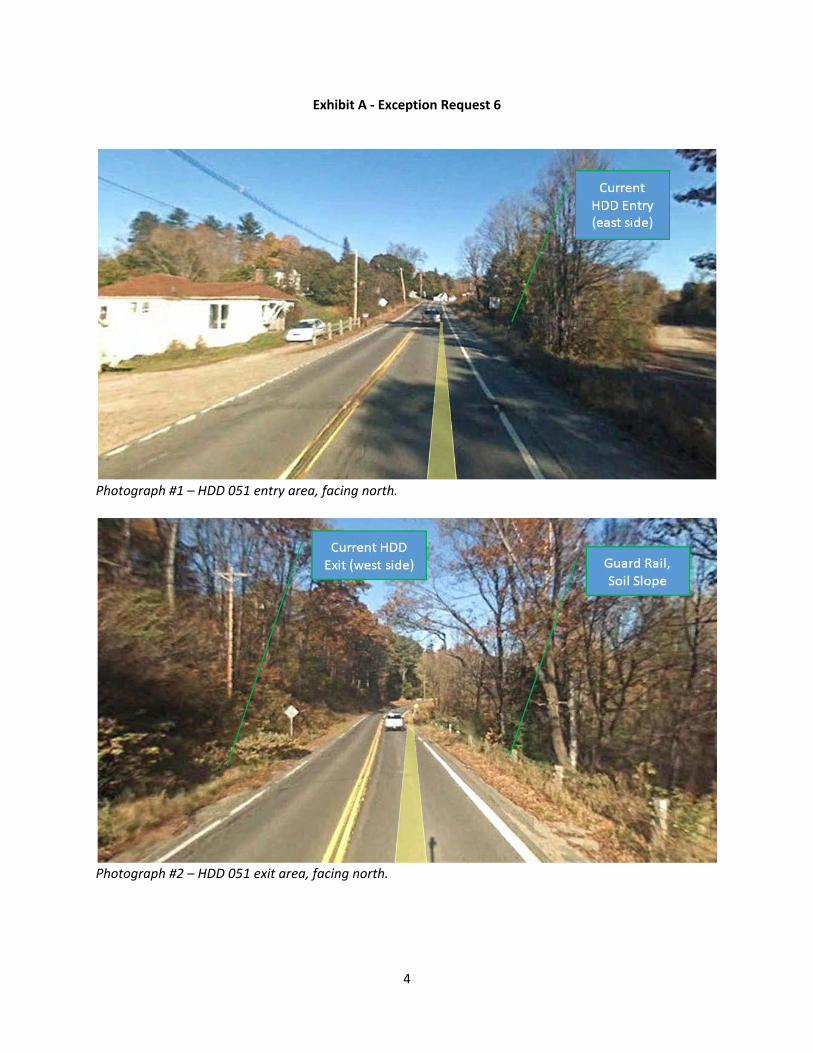
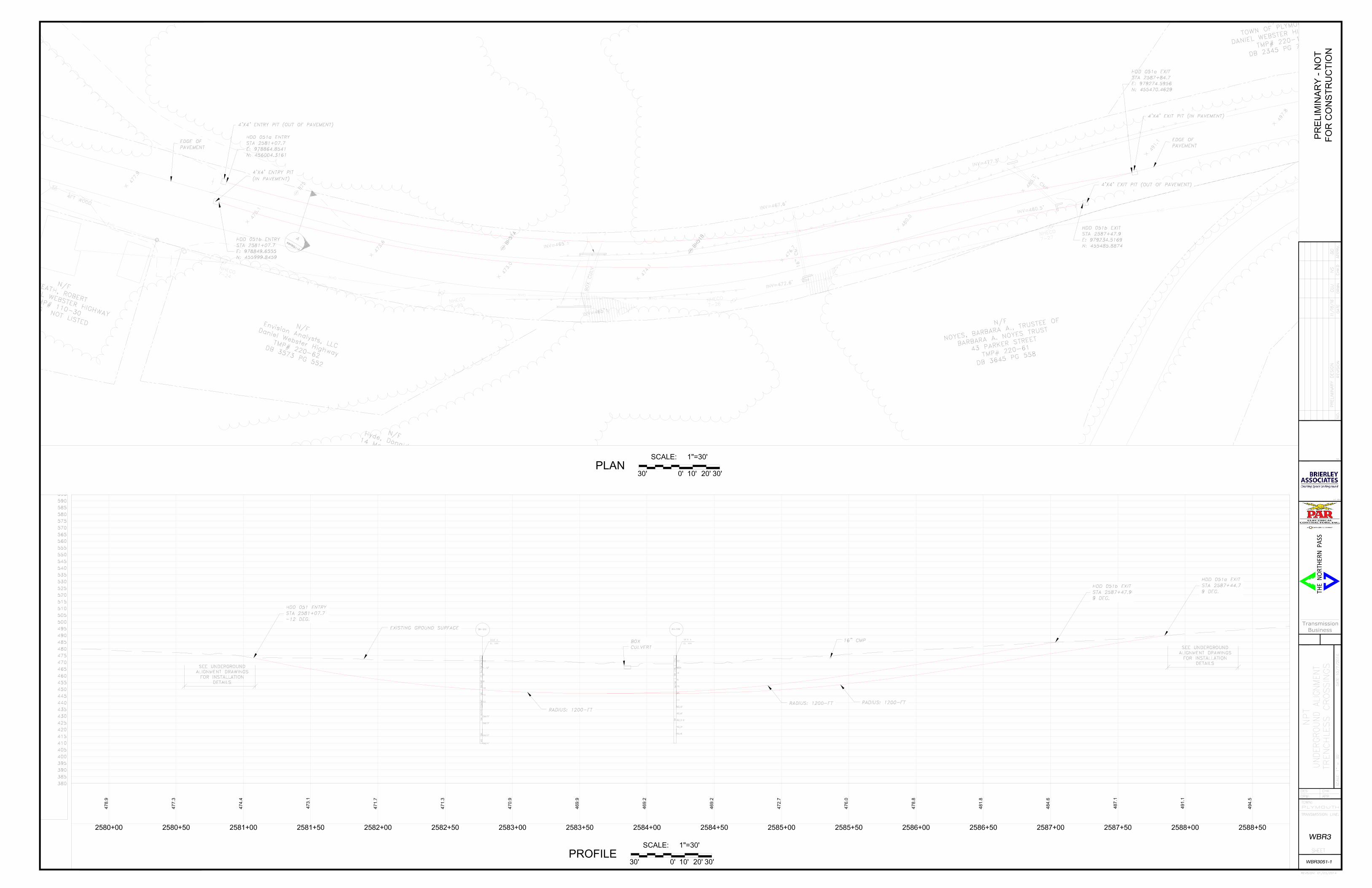
Exception Request No.: 6 Section: WBR3 Station: 2581+07 to 2587+85 Drawing No.: WBR3051‐01, WBR3051‐02 Survey Report Cross Reference No.: WBR3 C225 to C226 Exception Type: HDD Pits Within Pavement HDD Alignment Passing Under Pavement Summary of Justification for Exception NPT is requesting an exception from the UAM guidelines regarding the location of the HDD 051 entry and exit pits relative to the existing Route 3 pavement limits. HDD 051 extends from approximately STA 2581+07 to STA 2587+85, and is required to allow installation of the duct below a box culvert and small stream. This location involves two separate bores, which are shown crossing below Route 3 from east (HDD entry) to west (HDD exit). Each HDD installation requires two entry pits and two exit pits. Given the dimensions of the pits, the need to maintain separation between the two bores and separation from the edge of ROW, and the limited space available off the paved roadway at this location, one of the entry pits and one of the exit pits must be in the paved roadway. In addition, NPT is requesting an exception from the UAM guidelines to allow the location of the HDD 051 bore paths beneath the Route 3 pavement. The HDD bore paths will have no impact on the NHDOT highway structural box. Technical Discussion of Justification of Exception HDD Pit Within Pavement Each of the bores requires an entry pit and an exit pit (4 pits total). These pits will be approximately 4 feet x 4 feet in plan dimension (each). The HDD bores must be separated by about 20 feet at their maximum depth (25 feet) to minimize the risk of interference during drilling, and to accommodate thermal design criteria of the electric cables. The HDD entry and exit points at grade are approximately 10 feet apart, and 10 feet from the edge of ROW (for equipment access). (Note: because the typical degree of accuracy with HDD is +/‐ 5‐feet, the bore paths have been designed to maintain minimum separation of approximately 10 feet from each other.) The following elements are required to construct pits: (i) the center of the 2 entry pits (and the 2 exit pits) must be approximately 10 feet apart at grade; (ii) the 4 foot by 4 foot dimension of each pit; (iii) the need to start the bore at least 5 feet from the ROW edge; and (iv) the need for a level work area for the drill equipment. Consequently, NPT would need approximately 30 feet of level, stable, non‐vegetated clear space from the edge of pavement to the edge of the ROW at the location of the entry pits and 25 feet at exit pits to avoid impacting the paved area entirely. The alignment of the cable system adjacent to the entry location is on the east side of Route 3. The HDD 051 entry location is located on the east side of Route 3 due to the availability of work space in this area and to address the NHDOT’s comment to avoid road crossings where feasible. (See photograph #1 of entry location in Exhibit A and Sheet WBR3051‐01, 02.) The west side of Route 3 is not a feasible location for the entry location because it is occupied by utility poles and overhead power lines, and a residential driveway. The power lines limit the vertical profile of

2
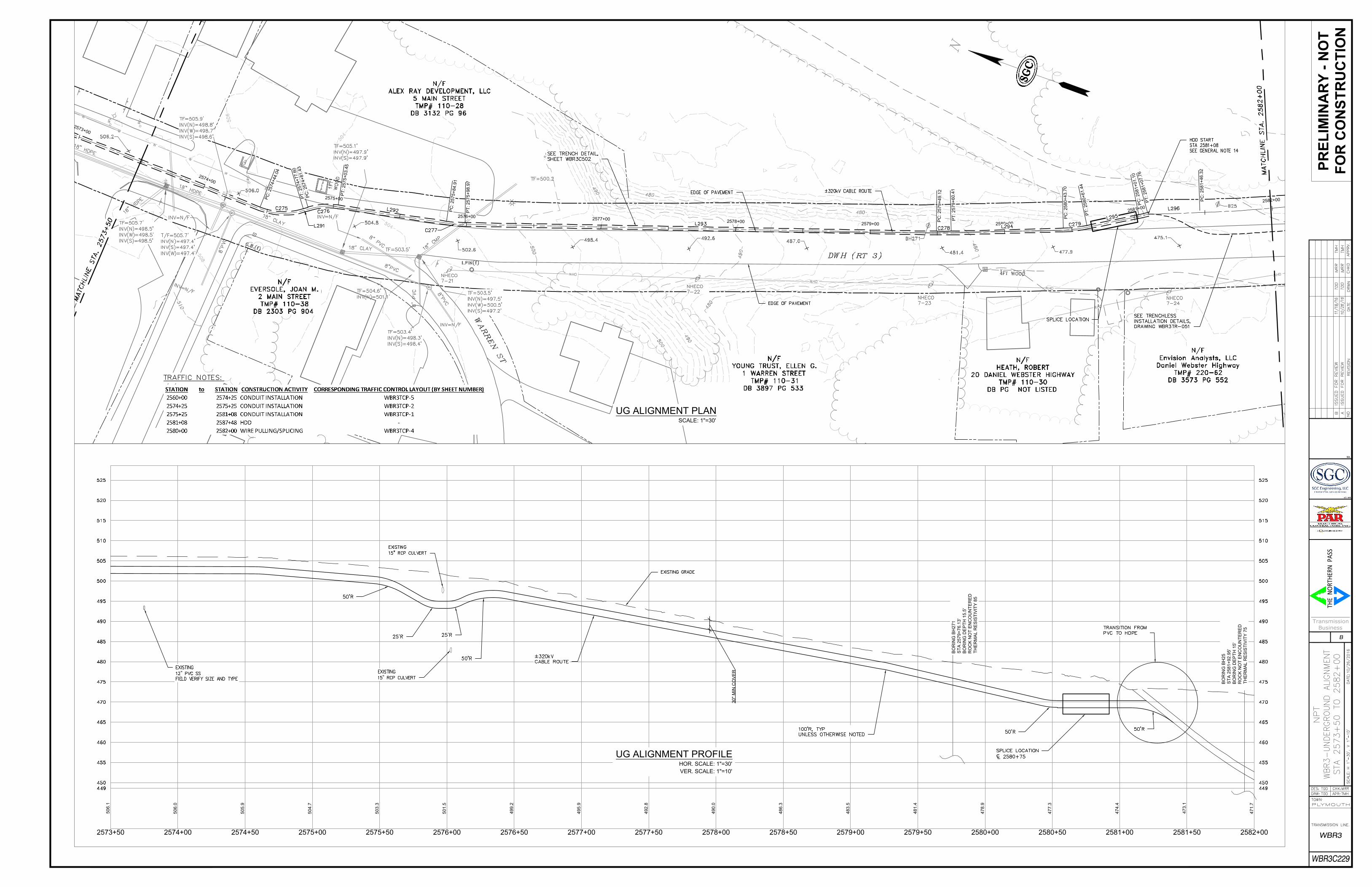
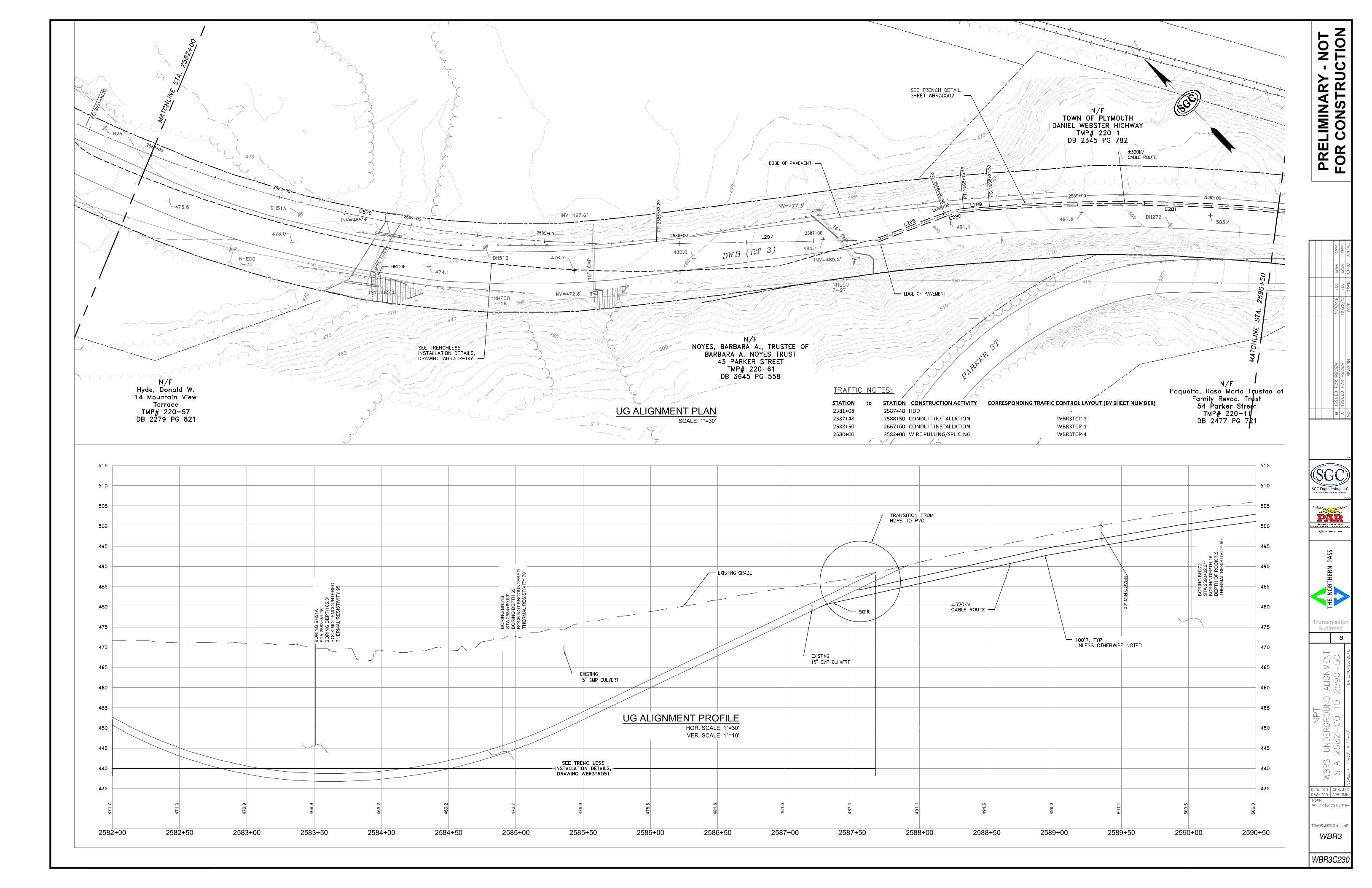
construction equipment required at the drill entry. In addition, use of the west side for the entry location would require an open‐trench road crossing (and NHDOT exception approval for such a crossing). There is not sufficient clear space at the HDD 051 entry location to keep both pits off the paved roadway. The distance between the edge of pavement and edge of ROW is approximately 20 feet (less than the required 30 feet), and there are mature trees that further limit construction in this area. The HDD 051 exit is located on the west side of Route 3, which requires that the HDD bore paths cross Route 3 between entry and exit. (See photograph #2 of exit location in Exhibit A and Sheet WBR3051‐01, 02.) The east (opposite) side of Route 3 is occupied by a guardrail. Beyond the guardrail, the ground surface slopes downward steeply to the east in the form of a wooded soil slope. This is shown in Photograph #2 in Exhibit A. Moving the HDD exit to the east side would require removal of the guardrail, and additional tree cutting. Exiting on the east side would also risk inadvertent surface drill fluid returns (“frac‐out”) in the vicinity of the soil slope (due to limited soil cover), which could result in undermining of Route 3. There is not sufficient clear space at the HDD 051 exit location to keep both pits off the paved roadway. The clear space on the west side of Route 3 off the paved road is approximately 20 feet (less than the required 25 feet), which is not enough space to keep both entry pits off the paved area. In sum, given the constraints at this HDD installation, NPT is seeking an exception to allow one of the HDD entry pits and one of the HDD exit pits to be located within the paved area. Excavation limits and work areas are shown on the attached drawings (WBR3051‐02). During construction, one lane will remain open to traffic at all times. HDD Alignment Passing Under Pavement From approximately Station 2581+07 to STA 2587+85, one or both of the bore paths are located beneath the pavement, as shown in drawings WBR3C229 and WBR3C230 attached. The distance between the edge of Route 3 pavement and the ROW (plan distance) is approximately 20 feet on either side of the road. With two (2) bores spaced at 20 feet and an offset of 5 feet from the ROW, it is not possible to avoid drilling beneath the pavement at this location. In addition, the entry and exit bore pits for this HDD are located on opposite sides of the road (for the reasons explained above), thereby necessitating that the bores cross under the road. The proposed bore paths are placed up to 25‐feet below the pavement and well below the pavement structural components of the highway and frost depths. Therefore, the design has no impact on the existing NHDOT facilities because it is below the structural box, frost zone, and all utilities. The depth of installation and trenchless construction method eliminate risk of settlement differential, pavement distress, or frost heaving that could adversely impact winter maintenance activities or the drivability of the roadway. Similarly, pavement matching concerns do not exist because there is no disturbance to the pavement. Moreover, the trenchless design in each of the requested exception locations is below all existing utilities and drainage structures, thereby eliminating potential for any impacts upon future maintenance activities or operations.

3
Impacts The design, as proposed, will not adversely affect the design, construction, stability, traffic, safety, environmental commitments, maintenance, or operation of Route 3. The installation of the ductbank and pavement restoration will be designed and constructed in accordance with conditions outlined in the NHDOT’s April 3, 2017 letter to the New Hampshire Site Evaluation Committee. The proposed depth of the installation meets NHDOT’s criteria relating to the structural box to minimize any potential conflicts with maintenance and future highway projects. A traffic control plan has been submitted to the NHDOT for this design and complies with the Manual on Uniform Traffic Control Devices. As to the portions of the HDD alignment under the NHDOT structural box, the proposed trenchless construction techniques will not impact the structural components of the highway, the frost zone, or other utilities, and therefore the proposed design will not adversely affect the design, construction, stability, traffic, safety, environmental commitments, maintenance, or operation of the highway. Supporting Documentation See photographs in Exhibit A. See attached drawing WBR3051‐01 showing the proposed HDD design geometry in plan and profile and drawings showing the work areas (WBR3051‐02). Also included for reference are duct bank drawings (WBR3C229 & WBR3C230) for the sections to the immediate north and south of the HDD installation.
4
Exhibit A ‐ Exception Request 6
Photograph #1 – HDD 051 entry area, facing north.
Photograph #2 – HDD 051 exit area, facing north.
PREL
IMIN
ARY
- NO
TFO
R C
ON
STR
UC
TIO
N
30'0' 10' 20'30'
SCALE: 1"=30'
30'0' 10' 20'30'
SCALE: 1"=30'
PLAN
PROFILE

PREL
IMIN
ARY
- NO
TFO
R C
ON
STR
UC
TIO
N
HDD 051 ENTRY AREA WORK SPACE HDD 051 EXIT AREA WORK SPACE
DETAIL A - HDD DUCT BUNDLESCALE: N.T.S.
30'0' 10' 20'
SCALE: 1"=30'
30' 60'0' 20' 40'
SCALE: 1"=60'
60'
2
5
7
3
+
0
0
2
5
7
4
+
0
0
2575+
00
2576+00
2577+00
2578+00
2579+00 2580+00
2
5
8
1
+
0
0
2582+
00
P
C
: 2
5
7
4
+
8
1
.4
3
P
C
: 2575+
84.91
PC
: 2580+
43.70
P
C
: 2
5
8
1
+
0
1
.1
0
PC
: 2581+
46.32
PC
: 2579+
49.12
P
C
:
2
5
7
4
+
4
4
.
0
4
P
T
: 2575+
03.45
PT
: 2575+
98.97
P
T
: 2
5
8
0
+
6
1
.4
4
P
T
: 2
5
8
1
+
0
7
.7
6
PT
: 2579+
60.41
P
T
: 2
5
7
4
+
7
7
.6
0
50
6.1
2573+50
50
6.0
2574+00
50
5.9
2574+50
50
4.7
2575+00
50
3.3
2575+50
50
1.5
2576+00
49
9.2
2576+50
49
5.9
2577+00
49
2.8
2577+50
49
0.0
2578+00
48
6.3
2578+50
48
3.5
2579+00
48
1.4
2579+50
47
8.9
2580+00
47
7.3
2580+50
47
4.4
2581+00
47
3.1
2581+50
47
1.7
2582+00
30
" M
IN
C
OV
ER
BO
RIN
G B
H2
71
ST
A 2
57
9+
76
.1
3'
BO
RIN
G D
EP
TH
1
5.5
'
RO
CK
N
OT
E
NC
OU
NT
ER
ED
TH
ER
MA
L R
ES
IS
TIV
IT
Y 1
29
BO
RIN
G B
H2
5
ST
A 2
58
1+
92
.9
5'
BO
RIN
G D
EP
TH
1
5'
RO
CK
N
OT
E
NC
OU
NT
ER
ED
TH
ER
MA
L R
ES
IS
TIV
IT
Y 2
57
BO
RIN
G B
H2
71
ST
A 2
57
9+
76
.1
3'
BO
RIN
G D
EP
TH
1
5.5
'
RO
CK
N
OT
E
NC
OU
NT
ER
ED
TH
ER
MA
L R
ES
IS
TIV
IT
Y 8
5
BO
RIN
G B
H2
5
ST
A 2
58
1+
92
.9
5'
BO
RIN
G D
EP
TH
1
5'
RO
CK
N
OT
E
NC
OU
NT
ER
ED
TH
ER
MA
L R
ES
IS
TIV
IT
Y 7
5
PR
EL
IM
IN
AR
Y - N
OT
FO
R C
ON
ST
RU
CT
IO
N
Transmission
Business
THE
NOR
THER
N P
ASS
WBR3
B
UG ALIGNMENT PLAN
SCALE: 1"=30'
UG ALIGNMENT PROFILE
HOR. SCALE: 1"=30'
VER. SCALE: 1"=10'
WBR3C229
2
5
8
2
+
0
0
2
5
8
3
+
0
0
2
5
8
4
+
0
0
2585+
00
2586+00
2587+00
2
5
8
8
+
0
0
2589+00
2590+00
P
C
:
2
5
8
1
+
4
6
.
3
2
P
C
:
2
5
8
8
+
0
0
.
9
6
PC
: 2588+
34.53
PT
: 2585+
83.29
PT
: 2588+
15.16
47
1.7
2582+00
47
1.3
2582+50
47
0.9
2583+00
46
9.9
2583+50
46
9.2
2584+00
46
9.2
2584+50
47
2.7
2585+00
47
6.0
2585+50
47
8.8
2586+00
48
1.8
2586+50
48
4.6
2587+00
48
7.1
2587+50
49
1.1
2588+00
49
4.5
2588+50
49
8.0
2589+00
50
1.1
2589+50
50
3.5
2590+00
50
6.0
2590+50
30
" M
IN
C
OV
ER
BO
RIN
G B
H2
72
ST
A 2
59
0+
02
.3
1'
BO
RIN
G D
EP
TH
1
6'
DE
PT
H O
F R
OC
K 7
.5
TH
ER
MA
L R
ES
IS
TIV
IT
Y 7
4
BO
RIN
G B
H5
1B
ST
A 2
58
4+
89
.6
9'
BO
RIN
G D
EP
TH
6
5'
RO
CK
N
OT
E
NC
OU
NT
ER
ED
TH
ER
MA
L R
ES
IS
TIV
IT
Y 1
34
BO
RIN
G B
H5
1A
ST
A 2
58
3+
51
.1
6'
BO
RIN
G D
EP
TH
6
5.3
'
RO
CK
N
OT
E
NC
OU
NT
ER
ED
TH
ER
MA
L R
ES
IS
TIV
IT
Y 6
43
BO
RIN
G B
H2
72
ST
A 2
59
0+
02
.3
1'
BO
RIN
G D
EP
TH
1
6'
DE
PT
H O
F R
OC
K 7
.5
TH
ER
MA
L R
ES
IS
TIV
IT
Y 5
0
BO
RIN
G B
H5
1B
ST
A 2
58
4+
89
.6
9'
BO
RIN
G D
EP
TH
6
5'
RO
CK
N
OT
E
NC
OU
NT
ER
ED
TH
ER
MA
L R
ES
IS
TIV
IT
Y 7
0
BO
RIN
G B
H5
1A
ST
A 2
58
3+
51
.1
6'
BO
RIN
G D
EP
TH
6
5.3
'
RO
CK
N
OT
E
NC
OU
NT
ER
ED
TH
ER
MA
L R
ES
IS
TIV
IT
Y 9
5
PR
EL
IM
IN
AR
Y - N
OT
FO
R C
ON
ST
RU
CT
IO
N
Transmission
Business
THE
NOR
THER
N P
ASS
WBR3
B
UG ALIGNMENT PLAN
SCALE: 1"=30'
UG ALIGNMENT PROFILE
HOR. SCALE: 1"=30'
VER. SCALE: 1"=10'
WBR3C230