no. 57215 & 57207
TRANSCRIPT
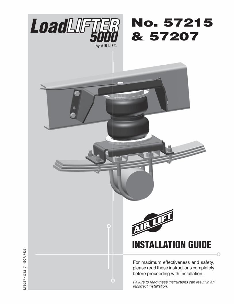
For maximum effectiveness and safety, please read these instructions completely before proceeding with installation.
Failure to read these instructions can result in an incorrect installation.
MN
-387
• (
3121
0) •
EC
R 7
433
INSTALLATION GUIDE
No. 57215& 57207

1MN-387
LoadLifter 5000
Introduction . . . . . . . . . . . . . . . . . . . . . . . . . . . . . . . . . . . 2Important Safety Notice . . . . . . . . . . . . . . . . . . . . . . . . . . . . . . . . . . . . . . . . . . . . . 2Notation Explanation . . . . . . . . . . . . . . . . . . . . . . . . . . . . . . . . . . . . . . . . . . . . . . . . 2
Installation Diagram . . . . . . . . . . . . . . . . . . . . . . . . . . . . 3Hardware List . . . . . . . . . . . . . . . . . . . . . . . . . . . . . . . . . . . . . . . . . . . . . . . . . . . . . 4Tools List . . . . . . . . . . . . . . . . . . . . . . . . . . . . . . . . . . . . . . . . . . . . . . . . . . . . . . . . . 4
Installing the LoadLifter 5000 System . . . . . . . . . . . . . . 45th Wheel Hitch . . . . . . . . . . . . . . . . . . . . . . . . . . . . . . . . . . . . . . . . . . . . . . . . . . . . 4 Getting Started . . . . . . . . . . . . . . . . . . . . . . . . . . . . . . . . . . . . . . . . . . . . . . . . . . . . 4Special Application Instructions . . . . . . . . . . . . . . . . . . . . . . . . . . . . . . . . . . . . . . . . 5Assembling the Air Spring Unit . . . . . . . . . . . . . . . . . . . . . . . . . . . . . . . . . . . . . . . . 6Positioning the Brackets . . . . . . . . . . . . . . . . . . . . . . . . . . . . . . . . . . . . . . . . . . . . . 7Attaching the Lower Bracket . . . . . . . . . . . . . . . . . . . . . . . . . . . . . . . . . . . . . . . . . . 7Attaching the Upper Bracket . . . . . . . . . . . . . . . . . . . . . . . . . . . . . . . . . . . . . . . . . . 8Securing the Air Spring to the Brackets. . . . . . . . . . . . . . . . . . . . . . . . . . . . . . . . . . 9Installing the Air Lines . . . . . . . . . . . . . . . . . . . . . . . . . . . . . . . . . . . . . . . . . . . . . . . 9Reinstalling the Fenderwell Liner (Late Model 4WD Dodge Only) . . . . . . . . . . . . .10Checking For Leaks. . . . . . . . . . . . . . . . . . . . . . . . . . . . . . . . . . . . . . . . . . . . . . . . .11
Maintenance and Servicing . . . . . . . . . . . . . . . . . . . . . . 11Maintenance Guidelines . . . . . . . . . . . . . . . . . . . . . . . . . . . . . . . . . . . . . . . . . . . . .12
Warranty and Return Policy . . . . . . . . . . . . . . . . . . . . . . 12
Product Use . . . . . . . . . . . . . . . . . . . . . . . . . . . . . . . . . . . 13Frequently Asked Questions . . . . . . . . . . . . . . . . . . . . . . . . . . . . . . . . . . . . . . . . . .13Tuning the Air Pressure . . . . . . . . . . . . . . . . . . . . . . . . . . . . . . . . . . . . . . . . . . . . . .13
Guidelines for Adding Air . . . . . . . . . . . . . . . . . . . . . . . . . . . . . . . . . . . . . . . . . . . . .14
Replacement Information . . . . . . . . . . . . . . . . . . . . . . . . 14
Contact Information . . . . . . . . . . . . . . . . . . . . . . . . . . . . 14
TABLE OF CONTENTS
1
2 MN-387
LoadLifter 5000
IntroductionThe purpose of this publication is to assist with the installation, maintenance and troubleshooting of the LoadLifter 5000 air spring kit. LoadLifter 5000 utilizes sturdy, reinforced, commercial grade single or double, depending on the kit, convolute bellows. The bellows are manufactured like a tire with layers of rubber and cords that control growth. LoadLifter 5000 kits are recommended for most ¾ and 1 ton pickups and SUVs with leaf springs and provide up to 5,000 lbs of load leveling support with air adjustability from 5-100 PSI. The kits are also used in motorhome rear kits and some motorhome fronts where leaf springs are used.
It is important to read and understand the entire installation guide before beginning installation or performing any maintenance, service or repair. The information here includes a hardware list, tool list, step-by-step installation information, maintenance tips, safety information and a troubleshooting guide.
Air Lift Company reserves the right to make changes and improvements to its products and publications at any time. For the latest version of this manual, contact Air Lift Company at (800) 248-0892 or visit our website at www.airliftcompany.com.
IMPORTANT SAFETY NOTICEThe installation of this kit does not alter the Gross Vehicle Weight Rating (GVWR) or payload of the vehicle. Check your vehicle’s owner’s manual and do not exceed the maximum load listed for your vehicle.
Gross Vehicle Weight Rating: The maximum allowable weight of the fully loaded vehicle (including passengers and cargo). This number — along with other weight limits, as well as tire, rim size and inflation pressure data — is shown on the vehicle’s Safety Compliance Certification Label.
Payload: The combined, maximum allowable weight of cargo and passengers that the vehicle is designed to carry. Payload is GVWR minus the Base Curb Weight.
NOTATION EXPLANATIONHazard notations appear in various locations in this publication. Information which is highlighted by one of these notations must be observed to help minimize risk of personal injury or possible improper installation which may render the vehicle unsafe. Notes are used to help emphasize areas of procedural importance and provide helpful suggestions. The following definitions explain the use of these notations as they appear throughout this guide.
INDICATES IMMEDIATE HAZARDS WHICH WILL RESULT IN SEVERE PERSONAL INJURY OR DEATH.
INDICATES HAZARDS OR UNSAFE PRACTICES WHICH COULD RESULT IN SEVERE PERSONAL INJURY OR DEATH.
INDICATES HAZARDS OR UNSAFE PRACTICES WHICH COULD RESULT IN DAMAGE TO THE MACHINE OR MINOR PERSONAL INJURY.
Indicates a procedure, practice or hint which is important to highlight.
DANGER
NOTE
WARNING
CAUTION

3MN-387
LoadLifter 5000
Installation Diagram
A
M
IJN
B
LH
F or G
I
H
C
I
J
N
D
E
OUTBOARD
FORWARD
fig. 1
ZV
YX
WZ
T

4 MN-387
LoadLifter 5000
Installing the LoadLifter 5000 System5TH WHEEL HITCH
NOTE FOR FORD TRUCKS ONLY: If you have a Reese-style 5th wheel hitch kit installed and you have purchased kit #57215, you need to order kit #57342 or contact Air Lift customer service for the correct brackets at (800) 248-0892. Ask for bracket kit #26275.
COMPRESSED AIR CAN CAUSE INJURY AND DAMAGE TO THE VEHICLE AND PARTS IF IT IS NOT HANDLED PROPERLY. FOR YOUR SAFETY, DO NOT TRY TO INFLATE THE AIR SPRINGS UNTIL THEY HAVE BEEN PROPERLY SECURED TO THE VEHICLE.
DANGER
GETTING STARTED1. Support the axle with jack stands, remove the wheels, and raise or lower to obtain normal
ride height (figs. 2 and 3).
8”
fig. 3
No Load in Truck
Remove wheels
fig. 2
Item Part # Description................................Qty A1 58437 Bellows (57215) ..................................2 A2 58491 Bellows (57207) ..................................2 B 07475 Upper bracket .....................................2 C 03102 Lower bracket .....................................2 D 11951 Roll plate .............................................4 E 33606 Elbow fitting .........................................2 F 10594 2” U-bolt ..............................................4 G 10583 4.5” U-bolt ...........................................4 H 18435 Nyloc nut ............................................16 I 18444 3/8” Flat washer .................................16 J 18427 3/8” Lock washer.................................8 K 13377 Upper bracket spacer* ........................8 L 18447 3/8” Large flat washer .........................8 M 17159 3/8” x 1.5” Washer head frame bolt ....8 N 17203 3/8” x 7/8” Hex head cap screw ..........8 O 01525 Spacer bar* .........................................4
Dodge Fenderwell Spacer Parts P 17182 ½” x 2” HHCS* ....................................2 Q 20947 Fenderwell liner spacer* .....................2 R 18419 10/32” Flat washer* .............................6 S 18425 ¼” Nyloc nut* ......................................2
Air Line Assembly T 20086 Air line assembly* ...............................1 U 10466 Tie strap* .............................................6 V 21230 Valve caps* .........................................2 W 18405 5/16” Flat washer* ...............................2 X 21234 Rubber washer* ..................................2 Y 18411 Small star washer* ..............................2 X 21233 5/16” Hex nut* .....................................4
*Not shown in fig. 1.
HARDWARE LIST
Missing or damaged parts? Call Air Lift customer service at (800) 248-0892 for a replacement part.
STOP!
5MN-387
LoadLifter 5000
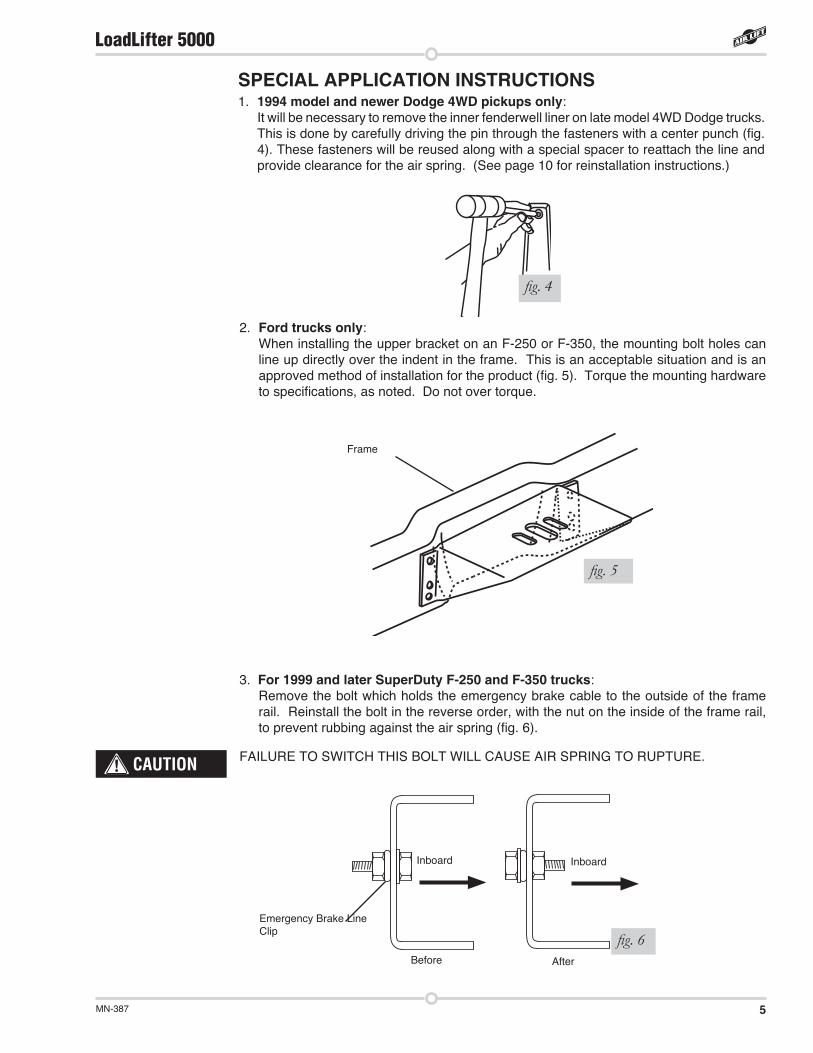
SPECIAL APPLICATION INSTRUCTIONS1. 1994 model and newer Dodge 4WD pickups only:
It will be necessary to remove the inner fenderwell liner on late model 4WD Dodge trucks. This is done by carefully driving the pin through the fasteners with a center punch (fig. 4). These fasteners will be reused along with a special spacer to reattach the line and provide clearance for the air spring. (See page 10 for reinstallation instructions.)
fig. 4
2. Ford trucks only:When installing the upper bracket on an F-250 or F-350, the mounting bolt holes can line up directly over the indent in the frame. This is an acceptable situation and is an approved method of installation for the product (fig. 5). Torque the mounting hardware to specifications, as noted. Do not over torque.
fig. 5
Frame
3. For 1999 and later SuperDuty F-250 and F-350 trucks: Remove the bolt which holds the emergency brake cable to the outside of the frame rail. Reinstall the bolt in the reverse order, with the nut on the inside of the frame rail, to prevent rubbing against the air spring (fig. 6).
FAILURE TO SWITCH THIS BOLT WILL CAUSE AIR SPRING TO RUPTURE.
fig. 6Emergency Brake Line Clip
AfterBefore
InboardInboard
CAUTION

6 MN-387
LoadLifter 5000
ASSEMBLING THE AIR SPRING UNITSee fig. 7 below for assembly.
1. Set a roll plate on both ends of the air spring. The radiused (rounded) edge of the roll plate will be towards the air spring so that the air spring is seated in both roll plates.
2. Install a 90° swivel air fitting. It should only be finger tight plus 11/2 turns. Do not overtighten.
3. Place the upper bracket onto the top of the air spring and roll plate with the legs facing down.
4. Set the air spring on the lower bracket aligning the two holes in the base of the air spring with the two outer slots in the top of the lower bracket.
5. Loosely attach the upper bracket to the assembly using flat washers, lock washers, and hex head bolts. Remember that the bracket legs face down.
6. Loosely attach the lower bracket to the assembly using flat washers, lock washers, and hex head bolts.
The flange on the bracket must face the outside (tire-side) of the vehicle.NOTE
fig. 7
Upper Bracket
90° Swivel Air Fitting
Lower Bracket
Roll Plates Air Spring
Hex Head Bolt
Lock Washer
Flat Washer
Bracket Leg
Flange
7MN-387
LoadLifter 5000
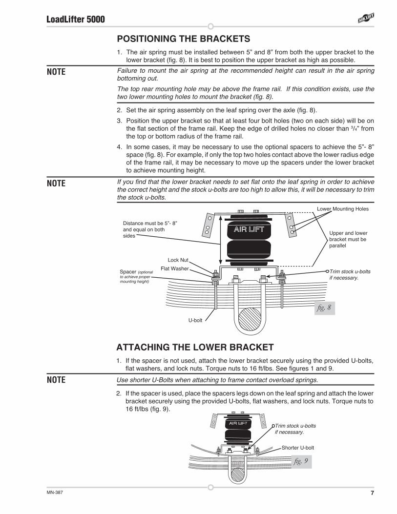
POSITIONING THE BRACKETS1. The air spring must be installed between 5” and 8” from both the upper bracket to the
lower bracket (fig. 8). It is best to position the upper bracket as high as possible.
Failure to mount the air spring at the recommended height can result in the air spring bottoming out.
The top rear mounting hole may be above the frame rail. If this condition exists, use the two lower mounting holes to mount the bracket (fig. 8).
2. Set the air spring assembly on the leaf spring over the axle (fig. 8).
3. Position the upper bracket so that at least four bolt holes (two on each side) will be on the flat section of the frame rail. Keep the edge of drilled holes no closer than 3/4” from the top or bottom radius of the frame rail.
4. In some cases, it may be necessary to use the optional spacers to achieve the 5”- 8” space (fig. 8). For example, if only the top two holes contact above the lower radius edge of the frame rail, it may be necessary to move up the spacers under the lower bracket to achieve mounting height.
If you find that the lower bracket needs to set flat onto the leaf spring in order to achieve the correct height and the stock u-bolts are too high to allow this, it will be necessary to trim the stock u-bolts.
ATTACHING THE LOWER BRACKET1. If the spacer is not used, attach the lower bracket securely using the provided U-bolts,
flat washers, and lock nuts. Torque nuts to 16 ft/lbs. See figures 1 and 9.
Use shorter U-Bolts when attaching to frame contact overload springs.
2. If the spacer is used, place the spacers legs down on the leaf spring and attach the lower bracket securely using the provided U-bolts, flat washers, and lock nuts. Torque nuts to 16 ft/lbs (fig. 9).
NOTE
NOTE
NOTE
fig. 9
Shorter U-bolt
Trim stock u-bolts if necessary.
fig. 8
Lock Nut
Spacer (optional to achieve proper mounting height)
Flat Washer
U-bolt
Distance must be 5”- 8” and equal on both sides Upper and lower
bracket must be parallel
Lower Mounting Holes
Trim stock u-bolts if necessary.

8 MN-387
LoadLifter 5000
ATTACHING THE UPPER BRACKETBEFORE DRILLING, CHECK THE BACK-SIDE OF THE FRAME FOR CLEARANCE ISSUES WITH THE BRAKE LINES, GAS LINES, AND ELECTRICAL LINES. ANY OBSTACLES WILL NEED TO BE TEMPORARILY RELOCATED TO CLEAR THE AREA.
1. Position the upper bracket so that it is parallel with the lower bracket and align the assembly vertically and horizontally.
2. Using the upper bracket as a template, center punch and drill one 3/8” locator hole through the frame at one of the top bolt holes (fig. 10).
After achieving the proper alignment, repeat for the opposite side of the bracket.NOTE
CAUTION
3. Except for Dodge vehicles, loosely install a washer head frame bolt, oversized flat washer), and lock nut (fig. 11).
For Dodge trucks only: The top two, or the bottom two, holes (depending on the model of the truck) will fall into a horizontal indentation. Spacers are provided to compensate for the indentation. Loosely install a washer head frame bolt, two upper bracket spacers, an oversized flat washer, and a lock nut for such instances (fig. 12).
4. Install a washer head frame bolt, oversized flat washer, and lock nut.
For Dodge trucks only: It may be necessary to add two of the provided spacers (fig. 12).
fig. 11 fig. 12
Upper Bracket
Washer Head Frame Bolt
Lock Nut
Oversized Flat Washer
Frame
Upper Bracket
Washer Head Frame Bolt
Lock Nut
Oversized Flat Washer
Frame
Spacer
All models, except some late model Dodge trucks
Dodge trucks with ditch(ditch can be on top or bottom portion of the
frame, depending on vehicle model)
3/8”
fig. 10

9MN-387
LoadLifter 5000
SECURING THE AIR SPRING TO THE BRACKETS1. Secure the air spring to the upper and lower brackets using an open ended 9/16” wrench
by tightening the two bolts on the top and the two bolts on the bottom of the spring assembly.
DUE TO THE THICKNESS OF THE LEAF SPRING STACK, TRIM ALL FOUR U-BOLTS ON EACH SIDE OF THE VEHICLE TO PREVENT BOTTOMING OUT ON THE UPPER BRACKET (FIG. 14).
2. Check bolts and connectors to ensure that all hardware is secure and repeat the process for the other side of the vehicle.
5. Remove the clamps and drill the remaining two holes. Install the appropriate hardware and torque the nuts to 44 ft/lbs.
6. Align the air spring uniformly between the upper and lower brackets and check the air spring alignment (fig. 13).
INSTALLING THE AIR LINESWHEN INSTALLING THE AIR LINES, THERE MUST BE AT LEAST SIX INCHES OF CLEARANCE BETWEEN THE AIR LINES AND ANY HEAT SOURCES.
1. Choose a convenient location for mounting the inflation valves. Popular locations for the inflation valves are: The wheel well flanges; The license plate recess in bumper; Under the gas cap access door; or through the license plate (fig. 15).
2. Secure air lines with provided tie straps.
Whatever the chosen location for the line is, make sure there is enough clearance around the inflation valves for an air chuck.
NOTE
CAUTION
CAUTION
Option 1Option 2
fig. 15
U-Bolts
fig. 14
Move the air spring in the slots of the upper and lower brackets to align. Make sure there is at least a thumbs width of clearance between the uninflated bag and the frame.
Frame
Bagfig. 13

10 MN-387
LoadLifter 5000
3. Drill a 5/16 “ hole to install the inflation valves.
4. Cut the air line assembly (AA) in two equal lengths.
WHEN CUTTING OR TRIMMING THE AIR LINE, USE A HOSE CUTTER (AIR LIFT P/N 10530), A RAZOR BLADE OR A SHARP KNIFE. A CLEAN, SQUARE CUT WILL ENSURE AGAINST LEAKS. DO NOT USE WIRE CUTTERS OR SCISSORS TO CUT THE AIR LINE. THESE TOOLS MAY FLATTEN OR CRIMP THE AIR LINE CAUSING IT TO LEAK AROUND THE O-RING SEAL INSIDE THE ELBOW FITTING (FIG 16).
5. Install the inflation valves as shown in fig. 17.
6. Keep at least 6” of clearance between the air line and heat sources, such as the exhaust pipes, muffler, or catalytic converter. Avoid sharp bends and edges. Leave at least 2” of slack when securing the air lines to allow for any movement that might pull on the air line (fig. 18).
7. Cut off air line leaving approximately 12” of extra air line. Insert the air line into the air fitting. Simply push the air line into the 90° swivel fitting until it bottoms out (9/16” of air line should be in the fitting).
REINSTALLING THE FENDERWELL LINER — LATE MODEL 4WD DODGE ONLY1. If this installation was on a late model 4WD Dodge truck, it is now necessary to reinstall
the inner fenderwell liner using the original fasteners and provided spacers to allow for air spring clearance (fig. 18).
fig. 16
fig. 17
fig. 18
CAUTION
Good Cut Bad Cut
Vehicle Body or Bumper
5/16” Flat Washer
Valve Cap
5/16” Hex Bolt
Air Line to Bellows
5/16” Hex Nut
Rubber Washer
Small Star Washer
1/2”
Before After

11MN-387
LoadLifter 5000
2. Place the spacer between the fenderwell liner and the fenderwell at the center hole in the fenderwell liner (the hole nearest the air spring). Attach using the 1/4” Hex Head Cap Screw (HHCS), the 10/32” flat washers, and 1/4” nyloc nut provided (fig. 19).
Fasten the HHCS with the washer and nut behind the fenderwell (fig. 19). Tighten securely.
3. Replace the remaining fenderwell liner rivets carefully. Push the rivets through the fenderwell liner by hand. They should push through completely (fig. 20).
4. From the opposite side, use a rubber mallet and carefully tap the rivet posts back into the rivets in order to secure them properly (fig. 21). Repeat this process for all remaining rivets.
CHECKING FOR LEAKS1. Inflate the air spring to 30 PSI.
2. Spray all connections and the inflation valves with a solution of 1/5 liquid dish soap and 4/5water to check for leaks. You should be able to spot leaks easily by looking for bubbles in the soapy water.
3. After the test, deflate the springs to the minimum pressure required to restore the normal ride height, but not less than 10 PSI.
4. Check the air pressure again after 24 hours. A 2 - 4 PSI loss after initial installation is normal. Retest for leaks if the loss is more than 5 lbs.
NOTE
fig. 19
Fenderwell
Fenderwell Liner
1/4” Nyloc Nut10/32” Flat Washer
Fenderwell Liner Spacer
10/32” Flat Washer
1/4” HHCS
Rivet Locations
fig. 20 fig. 21
Fenderwell
Maintenance and Servicing
5 PSI 100 PSI
FAILURE TO MAINTAIN CORRECT MINIMUM PRESSURE (OR PRESSURE PROPORTIONAL TO LOAD), BOTTOMING OUT, OVER-EXTENSION OR RUBBING
AGAINST ANOTHER COMPONENT WILL VOID THE WARRANTY.
Maximum Air PressureMinimum Air Pressure

12 MN-387
LoadLifter 5000
MAINTENANCE GUIDELINESBy following the steps below, vehicle owners will obtain the longest life and best results from their air springs.
1. Check the air pressure weekly.
2. Always maintain normal ride height. Never inflate beyond 100 PSI.
3. If you develop an air leak in the system, use a soapy water solution (1 part dish soap, 4 parts water) to check all air line connections and the inflation valve core before deflating and removing the air spring.
4. When increasing load, always adjust the air pressure to maintain the normal ride height. Increase or decrease pressure from the system as necessary to attain normal ride height for optimal ride and handling. Remember that loads carried behind the axle (including tongue loads) require more leveling force (pressure) than those carried directly over the axle.
FOR YOUR SAFETY AND TO PREVENT POSSIBLE DAMAGE TO YOUR VEHICLE, DO NOT EXCEED MAXIMUM GROSS VEHICLE WEIGHT RATING (GVWR), AS INDICATED BY THE VEHICLE MANUFACTURER.
5. Always add air to springs in small quantities, checking the pressure frequently. Sleeves require less air volume than a tire and inflate quickly.
6. Should it become necessary to raise the vehicle by the frame, make sure the system is at minimum pressure (5 PSI) to reduce the tension on the suspension/brake components. Use of onboard leveling systems do not require deflation or disconnection.
NOTE
CAUTION
Air Lift Company warrants its products, for the time periods listed below, to the original retail purchaser against manufacturing defects when used on catalog-listed applications on cars, vans, light trucks and motorhomes under normal operating conditions for as long as Air Lift manufactures the product. The warranty does not apply to products that have been improperly applied, improperly installed, used in racing or off-road applications, used for commercial purposes, or which have not been maintained in accordance with installation instructions furnished with all products. The consumer will be responsible for removing (labor charges) the defective product from the vehicle and returning it, transportation costs prepaid, to the dealer from which it was purchased or to Air Lift Company for verification.
Air Lift will repair or replace, at its option, defective products or components. A minimum $10.00 shipping and handling charge will apply to all warranty claims. Before returning any defective product, you must call Air Lift at (800) 248-0892 in the U.S. and Canada (elsewhere, (517) 322-2144) for a Returned Materials Authorization (RMA) number. Returns to Air Lift can be sent to: Air Lift Company • 2727 Snow Road • Lansing, MI • 48917.
Product failures resulting from abnormal use or misuse are excluded from this warranty. The loss of use of the product, loss of time, inconvenience, commercial loss or consequential damages is not covered. The consumer is responsible for installation/reinstallation (labor charges) of the product. Air Lift Company reserves the right to change the design of any product without assuming any obligation to modify any product previously manufactured.
This warranty gives you specific legal rights and you may also have other rights that vary from state-to-state. Some states do not allow limitations on how long an implied warranty lasts or allow the exclusion or limitation of incidental or consequential damages. The above limitation or exclusion may not apply to you. There are no warranties, expressed or implied including any implied warranties of merchantability and fitness, which extend beyond this warranty period. There are no warranties that extend beyond the description on the face hereof. Seller disclaims the implied warranty of merchantability. (Dated proof of purchase required.)
Air Lift 1000 ............................Lifetime LimitedRideControl ............................Lifetime LimitedSlamAir ...................................Lifetime LimitedLoadLifter 5000*.....................Lifetime LimitedEasyStreet Systems .................1 Year Limited
Load Controller (I) ....................2 Year LimitedLoad Controller (II) ...................2 Year LimitedSmartAir ....................................2 Year LimitedWireless AIR..............................2 Year LimitedOther Accessories ....................2 Year Limited
Warranty and Returns Policy
*formerly SuperDuty

13MN-387
LoadLifter 5000
Product UseFREQUENTLY ASKED QUESTIONSQ. Will installing air springs increase the weight ratings of a vehicle? No. Adding air springs will not change the weight ratings (GAWR, GCWR and/or GVWR)
of a vehicle. Exceeding the GWVR is dangerous and voids the Air Lift warranty.
Q. Is it necessary to keep air in the air springs at all times and how much pressure will they need?
The minimum air pressure should be maintained at all times. The minimum air pressure keeps the air spring in shape, ensuring that it will move throughout its travel without rubbing or wearing on itself.
Q. Is it necessary to add a compressor system to the air springs? No. Air pressure can be adjusted with any type of compressor as long as it can produce
sufficient pressure to service the springs. Even a bicycle tire pump can be used, but it’s a lot of work.
Q. How long should air springs last? If the air springs are properly installed and maintained they can last indefinitely.
Q. Will raising the vehicle on a hoist for service work damage the air springs? No. The vehicle can be lifted on a hoist for short-term service work such as tire rotation
or oil changes. However, if the vehicle will be on the hoist for a prolonged period of time, support the axle with jack stands in order to take the tension off of the air springs.
TUNING THE AIR PRESSUREPressure determination comes down to three things — level vehicle, ride comfort, and stability.
1. Level vehicle If the vehicle’s headlights are shining into the trees or the vehicle is leaning to one side,
then it is not level (fig. 22). Raise the air pressure to correct either of these problems and level the vehicle.
2. Ride comfort If the vehicle has a rough and harsh ride it may be due to either too much pressure or
not enough (fig. 23). Try different pressures to determine the best ride comfort.
3. Stability Stability translates into safety and should be the priority, meaning the driver may need
to sacrifice a perfectly level and comfortable ride. Stability issues include roll control, bounce, dive during braking and sponginess (fig. 24). Tuning out these problems usually requires an increase in pressure.
fig. 22 fig. 23Bad headlight aim Rough ride
Sway and body roll
fig. 24

14 MN-387
LoadLifter 5000
GUIDELINES FOR ADDING AIR1. Start with the vehicle level or slightly above.
2. When in doubt, always add air.
3. For motorhomes, start with 50-100 PSI in the rear because it can be safely assumed that it is heavily loaded.
4. If the front of the vehicle dives while braking, increase the pressure in the front air bags, if equipped.
5. If it is ever suspected that the air bags have bottomed out, increase the pressure (fig. 25).
6. Adjust the pressure up and down to find the best ride.
7. If the vehicle rocks and rolls, adjust the air pressure to reduce movement.
8. It may be necessary to maintain different pressures on each side of the vehicle. Loads such as water, fuel, and appliances will cause the vehicle to be heavier on one side (fig. 26). As much as a 50 PSI difference is not uncommon.
fig. 25 fig. 26Bottoming out Unlevel Level
Contact InformationIf you have any questions, comments or need technical assistance contact our customer service department by calling (800) 248-0892, Monday through Friday, 8 a.m. to 5 p.m. Eastern Time. For calls from outside the USA or Canada, our local number is (517) 322-2144.
For inquiries by mail, our address is PO Box 80167, Lansing, MI 48908-0167. Our shipping address for returns is 2727 Snow Road, Lansing, MI 48917.
You may also contact us anytime by e-mail at [email protected] or on the web at www.airliftcompany.com.
Replacement InformationIf you need replacement parts, contact the local dealer or call Air Lift customer service at(800) 248-0892. Most parts are immediately available and can be shipped the same day.
Contact Air Lift Company customer service at (800) 248-0892, , first if:• Parts are missing from the kit.• Need technical assistance on installation or operation.• Broken or defective parts in the kit.• Wrong parts in the kit.• Have a warranty claim or question.
Contact the retailer where the kit was purchased:• If it is necessary to return or exchange the kit for any reason.• If there is a problem with shipping if shipped from the retailer.• If there is a problem with the price.

Air Lift Company • 2727 Snow Road • Lansing, MI 48917 or PO Box 80167 • Lansing, MI 48908-0167 Toll Free (800) 248-0892 • Local (517) 322-2144 • Fax (517) 322-0240 • www.airliftcompany.com
Thank you for purchasing Air Lift products — the professional installer’s choice!
Printed in the USA
Need Help?Contact our customer service department by calling (800) 248-0892, Monday through Friday, 8 a.m. to 5 p.m. Eastern Time. For calls from outside the USA or Canada, our local number is (517) 322-2144.
Register your warranty online at www.airliftcompany.com/warrantyreg.htm