no. 328288 instruction bulletin s30 rev. 00 - tennant co · instruction bulletin no. 328288...
TRANSCRIPT

IB 328288 (05--2011) 1
INSTRUCTION BULLETINNo. 328288Machine: M20/T20/M30/
S30Published: 05--2011Rev. 00
NOTE: DO NOT DISCARD the Parts List from the Instruction Bulletin. Place theParts List in the appropriate place in the machine manual for futurereference. Retaining the Parts List will make it easier to reorderindividual parts and will save the cost of ordering an entire kit.
NOTE: Numbers in parenthesis ( ) are reference numbers for parts listed in Bill of Materials.
Installation instructions for kit number 322305
SYNOPSIS:This kit contains the parts needed to replace the steering column on M20 / T20 / M30 / S30 machines.Please follow step-by-step instructions.
SPECIAL TOOLS / CONSIDERATIONS: NONE(Estimated time to complete: S30 -- 1 hour (Pages 1--8), M20 / T20 / M30 -- 45 minutes (Pages 9--12)
PROTECT THE ENVIRONMENTPlease dispose of packaging materials, old machine components,and hazardous fluids in an environmentally safe manner accordingto local waste disposal regulations.
Always remember to recycle.
PREPARATION (S30):
1. Park the machine on a clean level surface.
2. Completely raise the hopper and engage thehopper support bar.
WARNING: Lift arm pinch point. Stayclear of hopper lift arms.
WARNING: Raised hopper may fall.Engage hopper support bar.
3. Turn off the engine, remove the key, and setthe parking brake.
FOR SAFETY: Before leaving or servicingmachine, stop on level surface, turn offmachine, remove key, and set parking brake.
4. Use the steering tilt to lower the steeringwheel to the lowest position.
INSTALLATION (S30):
1. Remove the plastic rivets holding the rubbershroud to the front of the machine. Set therivets aside. Refer to FIg. 1.
FIG. 1
IB 328288 (05--2011)2
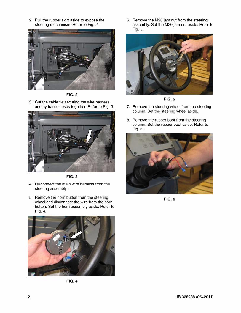
2. Pull the rubber skirt aside to expose thesteering mechanism. Refer to Fig. 2.
FIG. 2
3. Cut the cable tie securing the wire harnessand hydraulic hoses together. Refer to FIg. 3.
FIG. 3
4. Disconnect the main wire harness from thesteering assembly.
5. Remove the horn button from the steeringwheel and disconnect the wire from the hornbutton. Set the horn assembly aside. Refer toFIg. 4.
FIG. 4
6. Remove the M20 jam nut from the steeringassembly. Set the M20 jam nut aside. Refer toFig. 5.
FIG. 5
7. Remove the steering wheel from the steeringcolumn. Set the steering wheel aside.
8. Remove the rubber boot from the steeringcolumn. Set the rubber boot aside. Refer toFig. 6.
FIG. 6

IB 328288 (05--2011) 3
9. Remove the t--knob from the steering tiltassembly. It may be necessary to use towelsto avoid marring the surfaces of the knob andthe steering lock pin when removing thet--knob. Set the t--knob aside. Refer to Fig. 7.
FIG. 7
10. Remove the two M6 SEMS hex screwssecuring the steering tilt assembly to themachine. Set the M6 SEMS hex screwsaside. Refer to Fig. 8.
FIG. 8
11.Remove the steering tilt assembly from themachine. Set the steering tilt assembly aside.Refer to Fig. 9 and Fig. 10.
FIG. 9
FIG. 10
12. Remove the four M6 SEMS hex screwssecuring the steering assembly to themachine. Set the M6 SEMS hex screwsaside. Refer to Fig. 11.
FIG. 11

IB 328288 (05--2011)4
13. Remove the steering assembly from themachine. Refer to Fig. 12.
FIG. 12
14. Remove the steering column from thehydraulic steering control. Set the four M10hex screws aside. Refer to Fig. 13.
FIG. 13
15. Remove the flange bearings from the tiltsteering bracket. Set the flange bearingsaside. Refer to Fig. 14.
Flangebearings
Tiltsteeringbracket
Steering column
Collars
FIG. 14
16. Remove the tilt steering bracket from thesteering column. Set the tilt steering bracket,collars, and hardware aside. Refer to Fig. 14.

IB 328288 (05--2011) 5
17. Install the tilt steering bracket onto the newsteering column (1). Be sure the tilt steeringbracket is aligned on the steering column asshown in Fig. 16 and the white plastic horncontact is touching the lower collar on the tiltsteering bracket. Torque the socket screws to27--35 Ft. Lbs. (37--48 Nm).
FIG. 15
18. Apply Blue Loctite onto the threads of thefour M10 hex screws.
19. Use the four M10 hex screws to install thesteering column onto the hydraulic steeringcontrol. Torque the M10 hex screws to27--35 Ft. Lbs. (37--48 Nm). Refer to Fig. 16.
FIG. 16
Loctite is a trademark of the Henkel Corporation, USA
20. Install the flange bearings onto the tilt steeringbracket. Refer to Fig. 17.
FIG. 17
21. Insert the steering column assembly into themachine. Refer to Fig. 18.
FIG. 18
22. Use two M6 SEMS hex screws to secure thesteering assembly to the machine. Torque theM6 SEMS hex nuts to 5.6--7.3 Ft. Lbs.(7.6--9.9 Nm). Refer to Fig. 19.
FIG. 19

IB 328288 (05--2011)6
23. Use a 2 X 4 board to elevate the steeringcolumn assembly up into the machine. Referto Fig. 20.
FIG. 20
24. Install two M6 SEMS hex screws to securethe other side of the steering columnassembly in the machine. Torque the M6SEMS hex nuts to 5.6--7.3 Ft. Lbs. (7.6--9.9Nm). Refer to Fig. 21.
FIG. 21
25. Install the steering tilt assembly into themachine. Position the tilt steering locking pinin the top hole in the tilt steering bracket.Refer to Fig. 22.
FIG. 22
26. Apply Blue Loctite onto the treads of the tiltsteering locking pin and install the t--knob ontothe steering tilt assembly. Refer to Fig. 23.
FIG. 23
27. Hold the t--knob so the tilt steering locking pinis centered in the hole and does not touch anyof the the edges and install two M6 SEMS hexscrews to secure the steering tilt assembly tothe machine. Refer to Fig. 24.
FIG. 24
28. Install the rubber boot onto the steeringcolumn. Refer to Fig. 25.
FIG. 25
29. Apply Blue Loctite onto the threads of theM20 jam nut.

IB 328288 (05--2011) 7
30. Install the steering wheel onto the steeringcolumn and use the M20 jam nut to securethe steering wheel onto the column. Torquethe M20 jam nut to 10--13 Ft. Lbs. (13--18Nm). Refer to Fig. 26.
FIG. 26
31. Reassemble the horn button, reconnect the wireto the horn button, and insert the horn buttoninto the steering wheel. Refer to Fig. 27.
FIG. 27
32. Connect the horn lead on the main wireharness to the steering assembly. Refer toFig. 28 and Fig. 29.
FIG. 28
FIG. 29
33. Neatly bundle the main wire harness to thehydraulic hoses and use a wire tie to securethe bundle together. Refer to Fig. 30.
FIG. 30
34. Pull the steering tilt knob and move thesteering wheel through the various positionsto ensure the steering tilt assembly isfunctioning properly.
35. Reinstall the rubber skirt to the frame of themachine. Use extra rivets included in the kit toreplace rivets that may have been broken.
36. Disengage the hopper support bar.
37. Start the machine and lower the hopper.Press the horn button to ensure the hornfunctions.

IB 328288 (05--2011)8
24
FIG. 31
IB 328288 (05--2011) 9
PREPARATION (M20, M30, T20):
1. Park the machine on a clean level surface.
2. Turn off the engine, remove the key, and setthe parking brake.
FOR SAFETY: Before leaving or servicingmachine, stop on level surface, turn offmachine, remove key, and set parking brake.
3. Use the steering tilt to lower the steeringwheel to the lowest position.
4. Open the front shroud.
INSTALLATION (M20, M30, T20):Refer to Fig. 46 for Illustration.
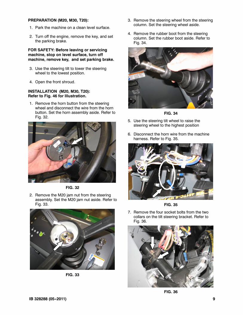
1. Remove the horn button from the steeringwheel and disconnect the wire from the hornbutton. Set the horn assembly aside. Refer toFig. 32.
FIG. 32
2. Remove the M20 jam nut from the steeringassembly. Set the M20 jam nut aside. Refer toFig. 33.
FIG. 33
3. Remove the steering wheel from the steeringcolumn. Set the steering wheel aside.
4. Remove the rubber boot from the steeringcolumn. Set the rubber boot aside. Refer toFig. 34.
FIG. 34
5. Use the steering tilt wheel to raise thesteering wheel to the highest position
6. Disconnect the horn wire from the machineharness. Refer to Fig. 35.
FIG. 35
7. Remove the four socket bolts from the twocollars on the tilt steering bracket. Refer toFig. 36.
FIG. 36

IB 328288 (05--2011)10
8. Slide the old column down through thesteering bellows.
9. Remove the four bolts mounting the column tothe hydraulic steering valve and discard theold steering column. Refer to Fig. 37.
FIG. 37
10. Apply Blue Loctite onto the threads of the fourM10 hex screws.
11. Fasten the new steering column onto thesteering valve with the horn wire facing thebattery. Torque the M10 hex screws to 27--35Ft. Lbs. (37--48 Nm). Refer to Fig. 38.
FIG. 38
12. Remove the steering column boot from thetop of the new steering column, then slide theassembly up through the steering bellows.
13. Loosely fasten the two collars over the newsteering column. Refer to Fig. 39.
FIG. 39
14. Position the steering column so that the top ofthe white collar (where the horn wire mounts)presses up against the lower collar. Thentighten the four socket bolts on the two collarsto secure in position. Torque the socketscrews to 27--35 Ft. Lbs. (37--48 Nm). Referto Fig. 40.
FIG. 40

IB 328288 (05--2011) 11
15. Tilt the steering wheel into all the positionsand check for clearance. Ensure that whenthe steering wheel is in the lowest positionthat the hoses do not contact the switch. If itdoes, loosen the two collars and reposition.Refer to Fig. 41.
FIG. 41
16. Ensure that when the steering wheel is in thehighest position that the hoses do not contactthe battery. If it does, loosen the two collarsand reposition. Refer to Fig. 42.
FIG. 42
17. Fasten the rubber boot onto the top of thesteering column. . Refer to Fig. 43.
FIG. 43
18. Mount the steering wheel and tighten with theM20 jam nut using Blue Loctite. Torque theM20 jam nut to 10--13 Ft. Lbs. (13--18 Nm).Refer to Fig. 44.
FIG. 44
19. Connect the (lower) horn wire harness to themachine harness. Refer to Fig. 45.
FIG. 45
20. Connect the horn assembly to the top steeringcolumn wire, then snap the horn assemblyinto the steering wheel. Refer to Fig. 46.
FIG. 46
21. Check the horn and steering for properoperation.

IB 328288 (05--2011)12
6
FIG. 47