no. 2017-00620, final written decision · final written decision 35 u.s.c. § 318(a); 37 c.f.r. §...
TRANSCRIPT
[email protected] Paper 79 571-272-7822 Entered: June 28, 2018
UNITED STATES PATENT AND TRADEMARK OFFICE
____________
BEFORE THE PATENT TRIAL AND APPEAL BOARD ____________
SKECHERS U.S.A., INC.,
Petitioner,
v.
NIKE, INC., Patent Owner. ____________
Case IPR2017-00620
Patent D723,783 S
____________
Before KEN B. BARRETT, GRACE KARAFFA OBERMANN, and SCOTT A. DANIELS, Administrative Patent Judges. OBERMANN, Administrative Patent Judge.
FINAL WRITTEN DECISION 35 U.S.C. § 318(a); 37 C.F.R. § 42.73
IPR2017-00620 Patent D723,783 S
2
I. INTRODUCTION
Pursuant to 35 U.S.C. § 318, we determine in this inter partes review
that Petitioner fails to carry its burden of showing by a preponderance of the
evidence that the challenged claim of U.S. Patent No. D723,783 S
(Ex. 1001, “the ’783 patent”) is unpatentable.
A. Procedural History and Asserted Challenges
On January 6, 2017, Petitioner filed a Petition (Paper 1, “Pet.”)
requesting an inter partes review of the claim of the ’783 patent. The
patented design relates to ornamental features located on the side and bottom
surfaces of a shoe sole. Ex. 1001, Figs. 1–3. On April 12, 2017, Patent
Owner filed a Preliminary Response. Paper 12 (“Resp.”).
The Petition asserts ten (10) grounds of unpatentability against the
claim. Pet. 5–6. On July 6, 2017, pursuant to 35 U.S.C. § 314, we instituted
review of the claim (Paper 13, “Dec.”) based on obviousness over:
1. RCD 00071 in view of RCD 00122;
2. RCD 0007 in view of RCD 0012 and CN13883; and
3. RCC 0007 in view of RCD 0012 and RCD 00054.
Paper 13, 37.
1 Certified Registration and Extract from the Register for Registered Community Design No. 000827613-0007 (Ex. 1003, “RCD0007”). 2 Certified Registration and Extract from the Register for Registered Community Design No. 000725247-0012 (Ex. 1005, “RCD0012”). 3 China Design Registration No. CN 301711388 S (Ex. 1009, “CN1388”). 4 Certified Registration and Extract from the Register for Registered Community Design No. 001874165-0005 (Ex. 1004, “RCD0005”).

IPR2017-00620 Patent D723,783 S
3
On October 26, 2017, Patent Owner filed a Response. Paper 41 (filed
under seal); Paper 57 (“Resp.”) (public version filed February 15, 2018). On
February 1, 2018, Petitioner filed a Reply. Paper 51 (“Reply”). We held a
consolidated final oral hearing5 on April 12, 2018. Paper 77 (“Tr.”).
On May 3, 2018, we entered an Order that added to the review each
additional ground of unpatentability asserted in the Petition. Paper 76, 1
(citing SAS Inst., Inc. v. Iancu, 138 S.Ct. 1348, 1359–1360 (U.S. Apr. 24,
2018)). Accordingly, we resolve in this decision seven (7) additional
grounds of obviousness (identified as grounds (4) through (10) below):
4. RCD00186 in view of RCD0012;
5. RCD0018 in view of RCD0012 and the ’853 patent7;
6. RCD0018 in view of RCD0012 and the ’725 patent8;
7. RCD0018 in view of RCD0012 and CN1388;
8. RCC0018 in view of RCD0012 and RCD0005;
5 The hearing was consolidated with IPR2017-00621 (“IPR621”), which involves the same parties and a related design patent. Concurrently herewith, we issue a Final Written Decision in IPR621. The parties aver also that the ’783 patent is at issue in Nike, Inc. v. Skechers U.S.A., Inc., Case No. 3:16-cv-00007-PK (D. Or.). Pet. 3; Paper 3, 2. Further, in IPR2016-00875 (“IPR875”), the Board denied institution of the inter partes review request by Petitioner. See Skechers U.S.A., Inc. v. Nike, Inc., Case IPR2016-00875, slip. op. 34–35 (PTAB Sept. 29, 2016) (Paper 11). 6 Certified Registration and Extract from the Register for Registered Community Design No. 000120449-0018 (Ex. 1002, "RCD0018"). 7 U.S. Patent No. D447,853 S (Ex. 1007, ‘the ’853 patent’). 8 U.S. Patent No. D520,725 S (Ex. 1008, ‘the ’725 patent’).

IPR2017-00620 Patent D723,783 S
4
9. RCD0007 in view of RCD0012 and the ’853 patent;
10. RCD0007 in view of RCD0012 and the ’725 patent.
Paper 76, 1.9
On May 10, 2018, the parties jointly advised the Board that the
addition of the above seven (7) grounds to the proceeding necessitated no
changes to the schedule or additional briefing. Paper 78, 1. Accordingly,
we assess the challenges asserted in the Petition based on the record
developed during trial.
B. Declaration Evidence
Petitioner relies on declaration testimony provided by Mr. Robert
John Anders (Ex. 1013; Ex. 1029). Patent Owner relies on declaration
testimony provided by Mr. Allan Ball (Ex. 2039). Based on their curricula
vitae and statements of qualifications, we find that Mr. Anders and Mr. Ball
both are qualified to opine about the perspective of an ordinarily skilled
designer. See Ex. 1013 §§ 5–23 (Mr. Anders’ statement of qualifications);
Ex. 1014 (Mr. Anders’ curriculum vitae); Ex. 2039 §§ 12–20 (Mr. Ball’s
statement of qualifications); Ex. 2040 (Mr. Ball’s curriculum vitae).
C. The Designer of Ordinary Skill
As we did in our institution decision, we find that a designer of
ordinary skill in the art would have had either (1) a degree in Industrial
Design combined with some work experience as a designer of footwear
designs; or (2) two years of direct experience creating footwear designs.
9 The Petition asserts U.S. Patent No. 6,115,945 (Ex. 1006, “the ’945 patent”) as a background reference. See, e.g., Pet. 5, 33.

IPR2017-00620 Patent D723,783 S
5
Dec. 7. That definition is consistent with Petitioner’s proposed definition.
Pet. 35 (Petitioner’s definition); Reply 2 (Petitioner, reasserting that
definition). Patent Owner, for its part, raises no persuasive information
tending to establish a different definition. Resp. 2 (Patent Owner, essentially
acquiescing to Petitioner’s definition). That definition also is consistent with
the disclosures reflected in the asserted prior art references. See Okajima v.
Bourdeau, 261 F.3d 1350, 1355 (Fed. Cir. 2001) (prior art itself can reflect
the appropriate level of ordinary skill in the art).
D. Claim Construction
The claim of the ’783 patent does not require express construction for
the purposes of this decision. On that point, we observe that Figures 1–3 of
the ’783 patent (Ex. 1001) reflect the scope of the patented design. To the
extent any explanation of that scope is necessary to our decision, we provide
it below in our analysis of the asserted challenge. Nidec Motor Corp. v.
Zhongshan Broad Ocean Motor Co. Ltd., 868 F.3d 1013, 1017 (Fed. Cir.
2017) (“we need only construe terms ‘that are in controversy, and only to the
extent necessary to resolve the controversy’” (quoting Vivid Techs., Inc. v.
Am. Sci. & Eng’g, Inc., 200 F.3d 795, 803 (Fed. Cir. 1999)).
II. DISCUSSION
“In determining the patentability of a design, it is the overall
appearance, the visual effect as a whole of the design, which must be taken
into consideration.” See In re Rosen, 673 F.2d 388, 390 (CCPA 1982). The
proper standard is whether the design would have been obvious to a designer
of ordinary skill who designs articles of the type involved, which, in this

IPR2017-00620 Patent D723,783 S
6
case, are shoe soles. See In re Nalbandian, 661 F.2d 1214, 1217 (CCPA
1981); Ex. 1001, Title, Fig. 1 (illustrating ornamental features on the bottom
surface of a shoe sole); Figs. 2–3 (illustrating ornamental features on the
lateral side surface of a shoe sole). For reasons that follow, we determine
that Petitioner fails to carry its burden of identifying a Rosen reference. See
Rosen, 673 F.2d at 391. As a consequence, Petitioner fails also to establish
that the challenged claim is unpatentable.
As a starting point, to make out a successful obviousness challenge,
Petitioner must identify “a reference, a something in existence, the design
characteristics of which are basically the same as the claimed design in order
to support a holding of obviousness. Such a reference is necessary whether
the holding is based on the basic reference alone or on the basic reference in
view of modifications suggested by secondary references.” Rosen, 673 F.2d
at 391. Accordingly, “the first step in an obviousness analysis for a design
patent requires a search of the prior art for a primary reference,” which
requires the tribunal “to: (1) discern the correct visual impression created by
the patented design as a whole; and (2) determine whether there is a single
reference that creates ‘basically the same’ visual impression.” Durling v.
Spectrum Furniture Co., 101 F.3d 100, 103 (Fed. Cir. 1996).
We address the two prongs of the Durling test in turn below.
A. The Visual Impression of the Patented Design as a Whole
The subject matter of the patented design is reflected in Figures 1–3 of
the ’783 patent. Taken together, Figures 1–3 define the visual impression of
the patented design as a whole.

IPR2017-00620 Patent D723,783 S
7
The Bottom Surface of the Patented Design (Fig. 1)
The patented design includes ornamental features located on the
bottom surface of the shoe sole, as illustrated in Figure 1, which is
reproduced below.
Ex. 1001, Fig. 1. Figure 1 is a view of the bottom surface of a shoe sole
with ornamental features illustrated as solid lines in the heel region and
unclaimed features illustrated by broken lines. See Ex. 1001, 1, Description
(“The broken lines showing the remainder of the shoe are for environmental
purposes only and form no part of the claimed design.”).
Figure 1 of the ’783 patent includes an ornamental feature depicted as
a solid line, located near the center of the heel region, surrounded by
concentric half ovals (also illustrated using solid lines). Ex. 1001, Fig. 1.
We, similar to the parties in their briefs, refer to that feature in this decision
IPR2017-00620 Patent D723,783 S
8
as “the channel element.”10 E.g., Resp. 14–15, Reply 7–8; Tr. 18:18–25
(Petitioner’s counsel, observing that “everyone agrees it’s a channel”).
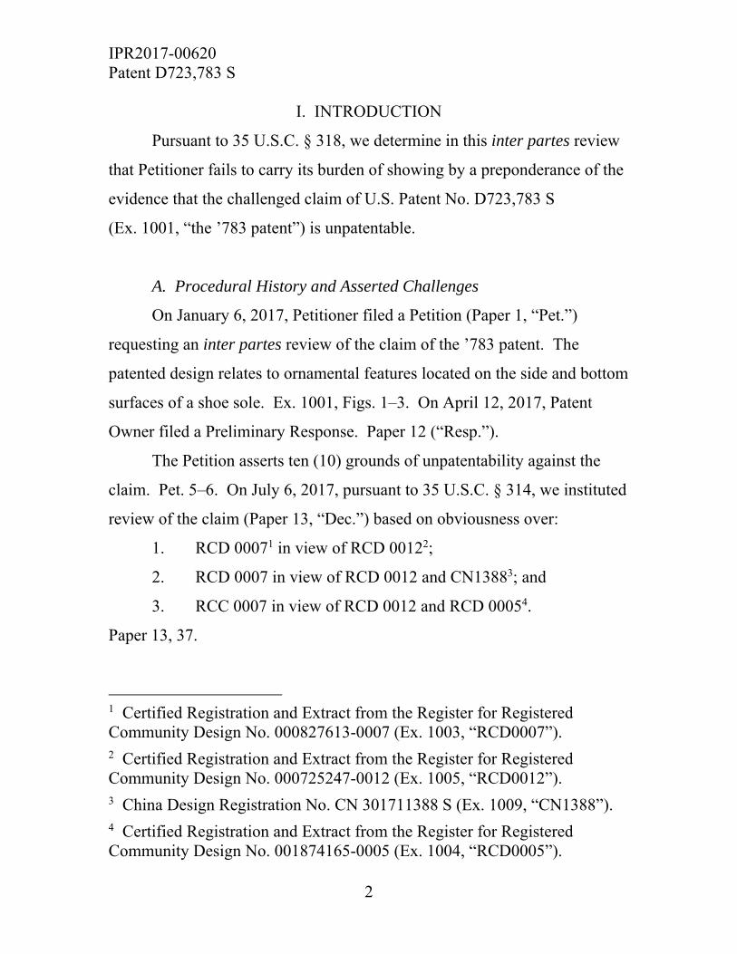
The Side Surface of the Patented Design (Figs. 2–3)
The patented design also includes ornamental features located on the
lateral (outward facing during normal wear) side surface of the shoe sole.
Those features are illustrated in Figure 2, reproduced below.
Id. at Fig. 2. Figure 2 is a front perspective view of the lateral side surface
of a shoe sole, with claimed features indicated in solid lines on the heel area
and an unclaimed remainder of the shoe indicated in broken lines.
10 By assigning that label to the feature, we make no conclusions as to its scope. For reasons that follow, we need not and do not provide a textual explanation of the scope of that claimed feature, except to observe that the scope is defined by Figure 1 and illustrated as a solid line surrounded by concentric half ovals in the claimed heel region of the patented design.
IPR2017-00620 Patent D723,783 S
9
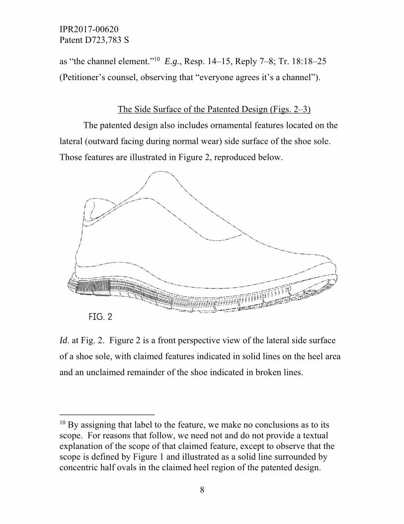
Another aspect of the patented design is shown in Figure 3,
reproduced below.
Id. at Fig. 3. Figure 3 is a lateral side view of the claimed heel portions of
the shoe sole in solid lines and unclaimed remainder of the shoe.
The Petition’s Lack of Analysis of the Channel Element
The Petition identifies three ornamental features as “key elements of
the design claimed in the ’783 patent.” Pet. 43, 63. When discussing the
visual impression created by the patented design as a whole, Petitioner
focuses on (1) “vertical sipes (or cracks)” located on the lateral “midsole”
side surface (Pet. 43, 63; see Ex. 1001, Figs. 2–3); (2) “vertical grooves” that
are located “between” those sipes (Pet. 43, 63; see Ex. 1001, Figs. 2–3); and
(3) a portion of the heel on the bottom surface of the shoe sole having “a
grid-like pattern of pads” (Pet. 43, 63; see Ex. 1001, Fig. 1). Patent Owner
asserts that a “visually evident” ornamental feature is overlooked in the
IPR2017-00620 Patent D723,783 S
10
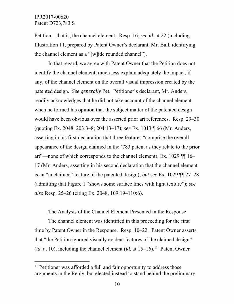
Petition—that is, the channel element. Resp. 16; see id. at 22 (including
Illustration 11, prepared by Patent Owner’s declarant, Mr. Ball, identifying
the channel element as a “[w]ide rounded channel”).
In that regard, we agree with Patent Owner that the Petition does not
identify the channel element, much less explain adequately the impact, if
any, of the channel element on the overall visual impression created by the
patented design. See generally Pet. Petitioner’s declarant, Mr. Anders,
readily acknowledges that he did not take account of the channel element
when he formed his opinion that the subject matter of the patented design
would have been obvious over the asserted prior art references. Resp. 29–30
(quoting Ex. 2048, 203:3–8; 204:13–17); see Ex. 1013 ¶ 66 (Mr. Anders,
asserting in his first declaration that three features “comprise the overall
appearance of the design claimed in the ’783 patent as they relate to the prior
art”—none of which corresponds to the channel element); Ex. 1029 ¶¶ 16–
17 (Mr. Anders, asserting in his second declaration that the channel element
is an “unclaimed” feature of the patented design); but see Ex. 1029 ¶¶ 27–28
(admitting that Figure 1 “shows some surface lines with light texture”); see
also Resp. 25–26 (citing Ex. 2048, 109:19–110:6).
The Analysis of the Channel Element Presented in the Response
The channel element was identified in this proceeding for the first
time by Patent Owner in the Response. Resp. 10–22. Patent Owner asserts
that “the Petition ignored visually evident features of the claimed design”
(id. at 10), including the channel element (id. at 15–16).11 Patent Owner
11 Petitioner was afforded a full and fair opportunity to address those arguments in the Reply, but elected instead to stand behind the preliminary

IPR2017-00620 Patent D723,783 S
11
directs us to Mr. Ball’s testimony that “[t]he bottom view of the claimed
design has a wide channel, which runs through the center of the shoe and
through the claimed portion of the outsole.” Ex. 2039 ¶ 41; Resp. 15.
Patent Owner argues, with support from Mr. Ball, that there exists in the
patented design a channel element having “edges that terminate mostly
within the claimed area before reaching the rearmost latitudinal sipe of the
claimed portion.” Resp. 15 (citing Ex. 2039 ¶ 41). We agree with that
assertion, which is supported by Figure 1 of the ’783 patent (Ex. 1001).
We are persuaded that Figure 1 of the ’783 patent depicts the channel
element in solid lines and, thereby, indicates that the feature impacts the
visual impression of the patented design as a whole. Ex. 1001, Fig. 1 (solid
line, near center of the claimed heel area, which is surrounded by concentric
half ovals). We further are persuaded that Illustration 11, prepared by
Mr. Ball, may be helpful to the reader in visualizing the relative placement
and size of the channel element that is illustrated in Figure 1 of the ’783
patent. Resp. 22 (reproducing Illustration 11). We reproduce Illustration 11
below.
claim construction set forth in our institution decision, which did not in our textual description mention explicitly the channel element. Reply 2–19; Dec. 7–10 (preliminary claim construction); see Egyptian Goddess, Inc. v. Swisa, Inc., 543 F.3d 665, 679 (Fed. Cir. 2008) (en banc) (With regard to design patents, it is well-settled that a design is represented better by an illustration than a description.). In the interests of reaching a fair result in this case, we granted Petitioner’s counsel leeway, at the final oral hearing, to address the visual impact of the channel element on the overall design, even though that issue was not addressed at all in the Petition, or adequately in the Reply. See, e.g., Tr. 7:11–10:4; 13:18–22:23.
IPR2017-00620 Patent D723,783 S
12
Resp. 22 (Illustration 11). Illustration 11 is a three-dimensional illustration
of a shoe sole that identifies, among other features, an element near the
center bottom surface of the shoe sole that is labelled “[w]ide rounded
channel.” We emphasize that the scope of the challenged claim, however, is
based on Figures 1–3 of the ’783 patent and not Illustration 11. Compare
Ex. 1001, Figs. 1–3, with Resp. 22 (Illustration 11).
The Analysis of the Channel Element Presented in the Reply
We take note of the itemized list of reasons why, in Petitioner’s view,
Illustration 11 “differs from the claimed design.” Reply 4–7. For example,
Petitioner argues that the channel element illustrated in Figure 1 of the ’783
patent is not necessarily “wide” or “rounded” in the patented design. Id.
at 4. We agree. Nonetheless, there is no genuine dispute surrounding the

IPR2017-00620 Patent D723,783 S
13
question whether the patented design includes a feature that is defined in
Figure 1 by a solid line and concentric half circles. Ex. 1001, Fig. 1.
On that point, Petitioner, in the Reply, advances no less than nine
figures that represent interpretations of the “surface lines” that define the
channel element in Figure 1, all of which are illustrated in the Reply as a
prominent ornamental feature. Reply 8; see id. at 12–16 (discussing a wide
array of possible interpretations of the “surface lines” in Figure 1, including
nine illustrations advanced by Petitioner, all of which demonstrate the
prominent visual impact of all of those possibilities).
Petitioner does not meaningfully dispute that the “surface lines” in
Figure 1 denote a channel element that is part of the patented design.12
Reply 8 (“Figure 1 shows surface lines in the center of the claimed region”).
As such, the channel element contributes to the overall visual impression
created by the patented design as a whole. Ex. 1001, Figs. 1–3. Even if we
accept that the “surface lines” (Reply 8) in Figure 1 may represent any one
of the nine configurations proposed by Petitioner, that does not undercut the
fact that the feature is prominent (that is, it impacts the visual impression of
the patented design as a whole). Reply 12–17 (proposing nine possible
interpretations of the channel element, all of which appear, even in
Petitioner’s illustrations, as prominent features of the patented design).
12 Petitioner’s counsel acknowledged, during the final oral hearing, that the channel element is a feature of the claimed design. Tr. 8:14–21; see id. at 18:18–25 (Petitioner’s counsel, observing that “everyone agrees it’s a channel”).
IPR2017-00620 Patent D723,783 S
14
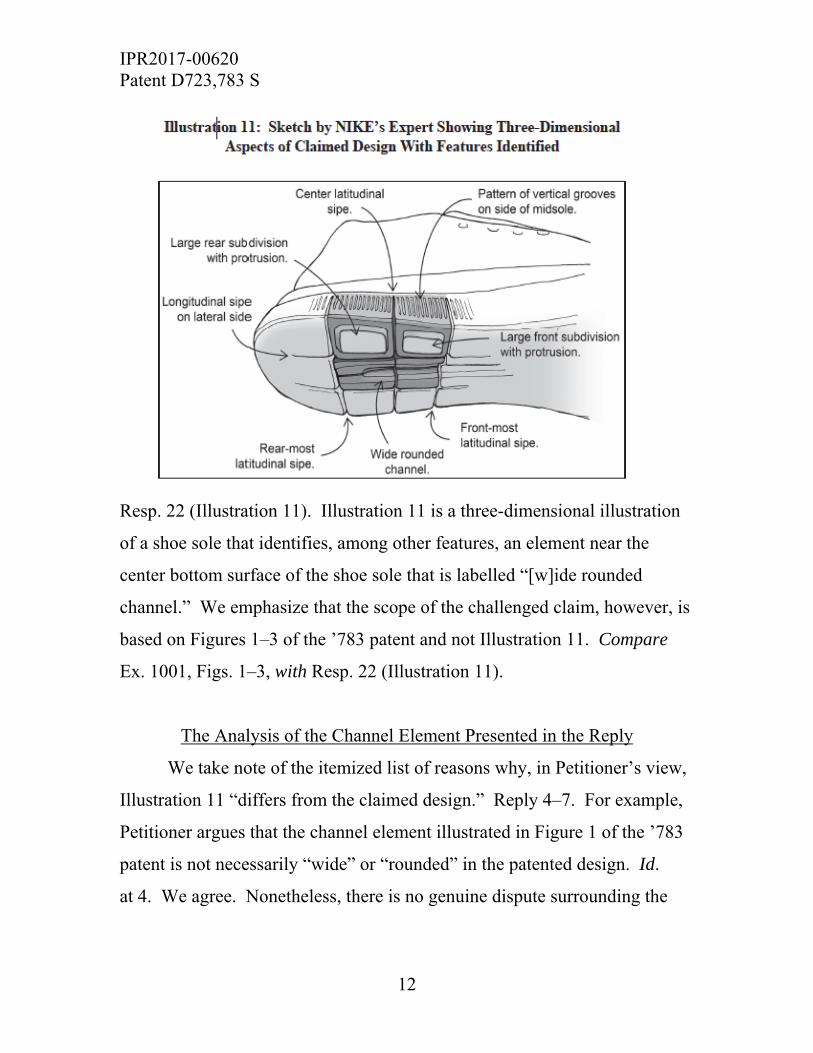
By way of example, we reproduce below the first of the nine figures
proposed by Petitioner (Reply 13) as a possible interpretation of the “surface
lines” (id. at 8) that define the channel element in Figure 1 of the ’783
patent.
Reply 13. The above figure contains three different views of the heel area of
a bottom surface of a shoe sole wherein the heel area is bisected in the mid-
heel region by a convex channel element.
Findings Regarding the Channel Element
The Petition does not identify the channel element and the Reply does
not effectively explain its impact on the overall visual impression of the
patented design. Instead, in the Reply, Petitioner advances argument that the
Board should not consider the channel element as a feature of the patented
design. See Pet. 36–39 (limiting claim construction analysis to three
features, and ignoring the channel element); Reply 2–3, 7–12 (advancing
argument that the channel element should not be interpreted as a feature of
the patented design).
IPR2017-00620 Patent D723,783 S
15
Petitioner’s own asserted renderings of the channel element make
plain that the feature impacts the visual impression of the patented design as
a whole. Reply 12–17 (advancing nine visual interpretations of Figure 1 of
the ’783 patent). We conclude that the channel element is a feature of the
patented design and, moreover, it impacts the visual impression created by
the design as a whole. Ex. 1001, Fig. 1 (solid line near center of the heel
area that is surrounded by concentric half ovals); see Resp. 15 (citing
Ex. 2039 ¶ 41) (Mr. Ball, providing persuasive opinion testimony regarding
the placement and size of the channel element in the patented design).
Petitioner’s own illustrations depict the channel element as a prominent
feature that impacts the overall visual impression of the patented design.
Reply 12–16 (advancing nine figures that, in Petitioner’s view, are possible
interpretations of the “surface lines” (id. at 8) in Figure 1 of the ’783 patent
that define the channel element).
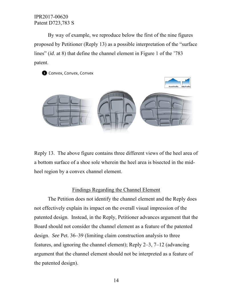
Arguably, the least visually significant interpretation of the channel
element proposed by Petitioner is a feature that is “flat with the surrounding
region having sipes”—but, even in Petitioner’s rendering of that
interpretation, the channel element contributes to the overall impression of
the patented design. Reply 16. We reproduce that illustration below.

IPR2017-00620 Patent D723,783 S
16
Id. The above figure is an illustration of two views of the heel area of a
bottom surface of a shoe sole wherein the heel area is bisected in the mid-
heel region by a flat channel element.
We are persuaded on this record that a preponderance of the evidence
shows that the channel element represents an ornamental feature of the
patented design that contributes toward “the correct visual impression
created by the patented design as a whole.” Durling, 101 F.3d at 103. We
are persuaded also that a discussion of the channel element is necessary to
any meaningful assessment of the overall visual impression of the patented
design. It is a feature that bisects the claimed heel portion of the shoe sole,
even in Petitioner’s view. Compare Reply 12–17 (Petitioner’s proposed
renderings of the channel element), with Ex. 1001, Fig. 1 (solid line and
concentric ovals that define the channel element). Under the circumstances,
for reasons explained in the next section, Petitioner should have identified
and discussed the channel element in the Petition.
Additional Observations on the Dispute Surrounding the Channel Element
Petitioner bears “the burden of proving a proposition of
unpatentability by a preponderance of the evidence.” 35 U.S.C. § 316(e).
Our rules require a successful petition to include “a detailed explanation of
the significance of the evidence including material facts.” 37 C.F.R.
§ 42.22(a)(2)). An issue bearing on the challenge is whether and how the
claimed channel element impacts the “visual impression created by the
patented design as a whole.” Durling, 101 F.3d at 103; see Ex. 1001, Fig. 1
(solid concentric ovals, which depict a channel element near the center of the
claimed grid-like pattern of pads).

IPR2017-00620 Patent D723,783 S
17
We are mindful of the dispute surrounding whether the solid line and
concentric ovals that define the channel element in Figure 1 of the ’783
patent represent, for example, a depression, a raised ornamental feature, or
simply a two-dimensional pattern consisting of lines drawn on a flat surface.
See Ex. 1001, Fig. 1 (showing solid lines that define and claim that feature);
Reply 12–17 (exploring at least nine possible interpretations of the “surface
lines” that represent the channel element). We are unpersuaded that
resolution of that dispute is necessary to our analysis. It is enough for us to
observe that the channel element is part of, and impacts the overall
impression of, the claimed design. Tr. 8:1–10:3, 50:3–52:18 (discussing the
dispute and confirming the parties’ agreement that the channel element is
part of the claimed design).
The Petition does not address the impact of the channel element on the
overall visual impression of the claimed design. See generally Pet. And the
Reply adheres to the preliminary claim construction that we provided in our
institution decision, which was based on a preliminary record that did not
identify explicitly the channel element. Reply 2–11; Dec. 7–10.
In the Reply, however, Petitioner for the first time acknowledges the
solid line and concentric ovals that represent the channel element in Figure 1
of the ’783 patent. Reply 8 (referring to “surface lines in the center of the
claimed region”). But, in the Reply, Petitioner does not explain adequately
whether or how that feature impacts “the correct visual impression created
by the patented design as a whole.” Durling, 101 F.3d at 103. Instead, as
explained above, Petitioner asserts that “the surface lines” apparent in
Figure 1 “can represent many features,” then proceeds to advance no less
than nine possible interpretations, without explaining how any of them

IPR2017-00620 Patent D723,783 S
18
would fail to impact the overall visual impression of the patented design.
Reply 12–18. Given these particular facts and circumstances, we determine
that Petitioner fails to provide “a detailed explanation of the significance of
the evidence” bearing on the extent to which the channel element contributes
to the overall impression of the patented design. 37 C.F.R. § 42.22(a)(2));
see supra n.10 (explaining that we afforded Petitioner’s counsel leeway at
the final oral hearing to address that issue); cf. Tr. 23:1–26:16 (Petitioner’s
counsel discussing de minimus changes in the context of a Rosen reference).
Petitioner also does not identify adequately “[h]ow the challenged
claim is to be construed.” 37 C.F.R. § 42.104(b)(3). The Petition nowhere
mentions the channel element, and the Reply advances a plethora of possible
interpretations of the channel element, without advancing any particular
interpretation. Reply 12–17. On this record, we find that Petitioner fails to
carry its “burden from the onset to show with particularity why the patent it
challenges is unpatentable.” Harmonic Inc. v. Avid Tech., Inc., 815 F.3d
1356, 1363 (Fed. Cir. 2016) (citing 35 U.S.C. § 312(a)(3) (requiring inter
partes review petitions to identify “with particularity” by reference to the
record “the evidence that supports the grounds for the challenge to each
claim”)). That burden of persuasion, moreover, never shifts to Patent
Owner. See Dynamic Drinkware, LLC v. Nat’l Graphics, Inc., 800 F.3d
1375, 1378 (Fed. Cir. 2015) (discussing the burdens in our administrative
review process).
Conclusions Regarding the First Prong of the Durling Test
A preponderance of the evidence supports a conclusion that Petitioner
fails to take account adequately of the channel element of the patented
IPR2017-00620 Patent D723,783 S
19
design and, therefore, fails also to identify “the correct visual impression
created by the patented design as a whole”—a required first step in
identifying a Rosen reference. Durling, 101 F.3d at 103. That failure,
standing alone, justifies our conclusion that Petitioner fails also to prove by a
preponderance of the evidence that the challenged claim of the ’783 patent is
unpatentable.
We next turn to the second prong of the Durling test, which presents
an independent basis for concluding that Petitioner fails to carry its burden
of proving that the challenged claim is unpatentable.
B. Petitioner Fails to Identify a Single Reference that Creates Basically the Same Visual Impression as the Patented Design
In order to prevail, Petitioner must identify “a reference, a something
in existence, the design characteristics of which are basically the same as the
claimed design in order to support a holding of obviousness.” Rosen, 673
F.2d at 391. The Durling test emphasizes that a Rosen reference is “a single
reference that creates ‘basically the same’ visual impression” as the patented
design. Durling, 101 F.3d at 103.
The Petition asserts that RCD0007 and RCD0018 qualify as Rosen
references. Pet. 43–50, 63–68; Reply 19–22 (additional arguments
pertaining to RCD0007). We address each in turn below.
RCD0007 (Ex. 1003)
Petitioner asserts that RCD0007 qualifies as a Rosen reference
because it discloses three “key elements” that are present in the patented
design: (1) vertical sipes along the midsole side surface of the shoe; (2) in
the medial view, vertical grooves along the center of the midsole between

IPR2017-00620 Patent D723,783 S
20
the sipes; and (3) a portion of the heel area on the bottom surface having a
grid-like pattern of pads. Pet. 63. Petitioner does not account for the
channel element of the patented design. Id. at 63–69.
We reproduce below a side-by-side comparison of RCD0007 and the
patented design that is advanced in the Petition. Pet. 65.
Id. The above figure is an annotated composite illustration that compares
ornamental features described as grooves located on a side surface of the
patented design (Ex. 1001, Fig. 3 (annotated)) to ornamental features
described as grooves located on a side surface design of RCD0007
(Ex. 1003, Fig. 3 (annotated)).
We reproduce below Petitioner’s figure that compares the heel regions
of the respective designs.

IPR2017-00620 Patent D723,783 S
21
Pet. 66. The above figure is a composite illustration that compares the
ornamental features located on the bottom surface of the patented design
(Ex. 1001, Fig. 1 (annotated)) to the ornamental features located on the
bottom surface of RCD0007 (Ex. 1002, Fig. 7 (annotated)).
Petitioner does not establish that RCD007 “creates ‘basically the
same’ visual impression” as the patented design, which includes the channel
element. Durling, 101 F.3d at 103. Neither the Petition nor the Reply
adequately accounts for the channel element, which is undeniably a feature
of the patented design. See Tr. 8:14–21 (Petitioner’s counsel, identifying, by
reference to Figure 1 of the ’783 patent, regarding the solid line and
surrounding concentric ovals, “I think it goes without saying that something
is depicted there”),18:18–25 (Petitioner’s counsel, observing that, as to that
IPR2017-00620 Patent D723,783 S
22
aspect of Figure 1, “everyone agrees it’s a channel”). As a result, the record
contains no information from which we reasonably can conclude that
RCD0007 qualifies as a Rosen reference by creating “basically the same”
impression as the patented design as a whole, including the channel element.
Durling, 101 F.3d at 103. The Petition should have raised and discussed the
channel element as part of Petitioner’s case-in-chief. See Ex. 1001, Fig. 1
(solid line and concentric ovals defining the channel element).
Further, in the patented design, claimed ornamental features are
located on the lateral (outward facing during normal wear) side surface of
the shoe sole. Ex. 1001, Figs. 2–3. By contrast, in order to make out that
RCD0007 qualifies as a Rosen reference, Petitioner relies on ornamental
features (including a pattern of vertical grooves) that are located on the
medial (inward facing during normal wear) side surface of the sole in
RCD0007. Ex. 1003, Fig. 3. We appreciate the candor of Petitioner’s
counsel in acknowledging that, when compared to RCD0007, those
ornamental features are located “on the complete opposite side of the shoe”
in the claimed design. Tr. 14:16–23. Patent Owner, for its part, directs us to
a sketch prepared by Mr. Ball that illustrates that difference. Resp. 28
(Illustration 13). We reproduce that sketch below.

IPR2017-00620 Patent D723,783 S
23
Id. The above figure is a composite illustration that shows Mr. Ball’s
interpretation of differences between the ornamental features of the patented
design as compared to the ornamental features of RCD0007. It is unclear on
this record how or why RCD0007 creates basically the same visual
impression as the patented design.
Patent Owner argues, persuasively, that to apply RCD0007 as a Rosen
reference, a designer of ordinary skill would be required to “move the
vertical grooves from the medial side of RCD0007 to a lateral side surface.”
Resp. 38. The designer would also need to ignore the existing “horizontal
grooves taught by the lateral side view of RCD0007” and, further, “modify
the now-relocated vertical grooves to extend only within the side view,
thereby disregarding RCD0007’s teaching to continue vertical side grooves

IPR2017-00620 Patent D723,783 S
24
around to bottom surfaces of the shoe as outsole grooves.” Id. We agree
with Patent Owner that “nothing in the Petition explains how or why” an
ordinarily skilled designer “would accomplish this relocation and
modification of prior design elements at the time of the invention.” Id. (and
evidence of record cited therein). Petitioner responds that making those
modifications would have been “obvious to try” (Reply 26–27), but that
observation, even if true, does not speak to the question whether RCD0007,
without modification, creates “‘basically the same’ visual impression” as the
patented design. Durling, 101 F.3d at 103.
On this record, we determine that Petitioner fails to establish by a
preponderance of the evidence that RCD0007 qualifies as a Rosen reference.
Accordingly, Petitioner fails also to establish by a preponderance of the
evidence that the challenged claim is unpatentable based on the grounds that
assert RCD0007 as a Rosen reference. See Pet. 7–8 (asserting RCD0007 as
the primary reference in the challenges identified as Grounds 6–10).
RCD0018 (Ex. 1002)
Petitioner asserts that RCD0018 qualifies as a Rosen reference
because it discloses three “key elements” that are present in the patented
design: (1) vertical sipes along the midsole side surface of the shoe; (2) in
the medial view, vertical grooves along the center of the midsole between
the sipes; and (3) a portion of the heel area on the bottom surface having a
grid-like pattern of pads. Pet. 43. Here again, Petitioner does not account
for the channel element of the patented design. Id. at 43–46.
Petitioner advances the following illustrations that compare the
ornamental features of RCD0018 to those of the patented design.

IPR2017-00620 Patent D723,783 S
25
Pet. 45–46.
Id. at 45. The above figure is an annotated composite illustration that
compares ornamental features described as sipes located on a side surface of
the patented design (Ex. 1001, Fig. 3 (annotated)) to ornamental features
described as sipes located on a side surface design of RCD0018 (Ex. 1002,
Fig. 3 (annotated)).
Pet. 45. The above figure is an annotated composite illustration that
compares ornamental features described as grooves located on a side surface
of the patented design (Ex. 1001, Fig. 3 (annotated)) to ornamental features
described as grooves located on a side surface design of RCD0018
(Ex. 1002, Fig. 3 (annotated)).

IPR2017-00620 Patent D723,783 S
26
Pet. 46. The above figure is an annotated reproduction of Figure 1 of
the ’783 patent (Ex. 1001) in which Petitioner asserts that a highlighted grid-
like pattern of pads located on the heel area on the bottom surface of a shoe
sole is the “claimed portion” of the patented design.
The above figure is an annotated reproduction of Figure 7 of RCD0018 (Ex.
1002), which illustrates the bottom surface of the shoe sole disclosed in
RCD0018.
IPR2017-00620 Patent D723,783 S
27
In our institution decision, based on the preliminary record, we found
that Petitioner did not show that RCD0018 qualifies as a Rosen reference.
Dec. 15–16. Nothing adduced during trial changes our view on that point.
Specifically, RCD0018 “fails to disclose outsole pistons that protrude from
the surface of the outsole” as required by the patented design. Id. at 16; see
Ex. 1001, Fig. 1 (illustrating pistons that protrude in the claimed heel area on
the bottom surface of the shoe sole); see also id. at Figs. 2, 3 (showing the
protruding pistons from a side perspective); Dec. 8 (explaining that
Petitioner’s own annotated figures from the ’783 patent, submitted in
IPR875 (see supra n.5), indicate that “the outsole pistons protrude from the
outsole” in the patented design) (and evidence cited therein).
In addition, our reasoning above in connection with RCD0007 applies
with equal force to RCD0018. Specifically, Petitioner does not establish
how or why RCD0018 creates basically the same visual impression as the
patented design as a whole, which includes the channel element. Pet. 43–46.
On this record, we determine that Petitioner fails to establish by a
preponderance of the evidence that RCD0018 qualifies as a Rosen reference.
Accordingly, Petitioner fails also to establish by a preponderance of the
evidence that the challenged claim is unpatentable on the grounds that assert
RCD0018 as a Rosen reference. See Pet. 7–8 (asserting RCD0018 as the
primary reference in the challenges identified as Grounds 1–5).
IPR2017-00620 Patent D723,783 S
28
Conclusions Regarding the Second Prong of the Durling Test
A preponderance of the evidence supports a conclusion that Petitioner
fails to identify “a single reference that creates ‘basically the same’ visual
impression” as the patented design. Durling, 101 F.3d at 103. That failure
provides an independent basis for concluding that Petitioner fails to carry its
burden of proving that the subject matter of the challenged claim of the ’783
patent would have been obvious at the time of the invention.
III. CONCLUSION
Petitioner does not show by a preponderance of the evidence that the
challenged claim of the ’783 patent is unpatentable.
IV. ORDER
It is
ORDERED that Petitioner does not show by a preponderance of the
evidence that the challenged claim of U.S. Patent No. D723,783 S is
unpatentable; and
FURTHER ORDERED that, because this is a Final Written Decision,
parties to the proceeding seeking judicial review of the decision must
comply with the notice and service requirements of 37 C.F.R. § 90.2.

IPR2017-00620 Patent D723,783 S
29
PETITIONER:
Samuel K. Lu Michael R. Fleming Talin Gordnia Morgan Chu IRELL & MANELLA LLP [email protected] [email protected] [email protected] [email protected]
PATENT OWNER:
Christopher J. Renk Erik S. Maurer Audra Eidem Heinze Kurt Reister Michael J. Harris BANNER & WITCOFF, LTD [email protected] [email protected] [email protected] [email protected] [email protected]