no. 1860 the elasticity of pipe bends - urząd...
TRANSCRIPT
No. 1860
THE ELASTICITY OF PIPE BENDS
B y S a b in C r o c k e r , D e t r o it , M ic h .
Assoeiate-M ember of the Society and
St e r l in g S . S a n f o r d , D e t r o it , M ic h .
Junior Member of the Society
In this paper the authors develop in detail mathematical formulas connecting the deflection of different types of pipe bends with the force producing deflection, and also expressing the stress set up as a function of the observed deflection and the constants of the bend. They describe experiments made to check force vs. displacement, and present charts for use in selecting the proper size and shape of bends to take care of a given expansion, and to determine the force exerted by a bend when in a given state of deflection. In general they recommend bends of larger dimensions than are ordinarily used, and their figures are said to lie on the side of safety. In some cases the bends tested showed a greater flexibility than anticipated, due to minute folds formed on the compression side when bending pipe to short radius.
rT ,HE use of expansion loops, offsets in the line, right-angled turns and similar devices to furnish flexibility for expansion and con
traction in pipe lines resulting from temperature changes, has been general practice for years. Such bends, which utilize the elasticity of the pipe itself, are very commonly used for high-pressure work in preference to slip joints, corrugated expansion joints, or swivel offsets in which screwed elbows are arranged to turn on pipe threads. The use of pipe bends reduces internal friction in the piping by providing easy turns, eliminates unnecessary fittings and joints, and facilitates clearing other pipes and structural interferences. The required flexibility can be obtained in some cases by introducing in the line a member consisting of some form of expansion bend like those illustrated in Figs. 4, 5 and 6 , or, what is more common, it may be accomplished by directional changes in the whole line of piping. An ideal condition for the latter exists where two long runs of pipe can be placed at right angles to each other, as is
Presented at the Annual Meeting, New York, December 4 to 7, 1922, of T h e A m e r ic a n S o c ie ty o f M e c h a n i c a l E n g in e e r s .
547
5 4 8 ELASTICITY OF P IP E BENDS
frequently done, for example, in a main steam line from boiler to turbine.
2 Up to the present time the disposal of expansion and contraction in power-plant piping has been largely a m atter of judgment rather than of rational calculation on the part of the designer. This has been due to a general lack of knowledge or interest regarding the principles and methods involved in calculating the forces and stresses resulting from the expansion of piping. However, if certain rather fundamental principles of engineering mechanics are brought into play, it is usually possible to determine numerical values with fair accuracy during the progress of design, and make use of this knowledge to improve the piping layout. As the drift toward higher steam pressures and temperatures in turbine practice continues, the problem becomes more and more important. Since there is also a tendency for the steam turbine to grow smaller relative to the size of the steam line to which it is connected, there is a danger that excessive stresses will be set up in the turbine casing as a result of expansion in the pipe line unless the piping designer knows how to calculate the forces involved. This paper is presented to set forth a method of attacking the problem. I t also shows wherein the authors’ methods and test results differ from the work of previous contributors to the subject and the extent to which they check earlier work.
3 The amount of expansion to be cared for in a pipe line can be accurately computed, provided the temperature range between extreme hot and cold conditions, the length of pipe, and the coefficient of expansion for the material are known. Having computed the amount of expansion or elongation of the pipe, the problem resolves itself into determining whether the piping arrangement under consideration has sufficient “ spring” to absorb this elongation without producing either undue fiber stress in the material or excessive forces tending to tear the piping loose from its anchors. At the same time the proportions of the line must be economical and be adjusted to clear any structural interferences in the plant. Wall thickness and diameter of pipe, radius of curvature, and general layout all affect the flexibility which can be obtained with a given run of pipe.
4 The inadequacy of the usual methods of steam-pipe design has been brought forcibly to the attention of The Detroit Edison Company by several minor mishaps during the past few years. Fortunately, none of these was of a serious nature, but they did serve to show that piping laid out according to the best modem practice may be subject to forces of unexpected proportions. Thus in one instance
S. CBOCKEB AND S. S. SANFOBD 5 4 9
unexpectedly large reactions caused a 14-in. high-pressure steam main to tear loose from what was supposed to be an adequate anchorage. This incident, and others of a somewhat similar nature, led those responsible for design and operation to ask themselves whether such failures could not be avoided by more intelligent design. Consequently, in undertaking the design of the company’s Marysville power plant, where the elongation per hundred feet of steam pipe amounts to almost seven inches and the steam pressure is 300 lb. per sq. in., it was decided tha t pipe expansion must be cared for in a rational manner if such a thing were possible. Accordingly, the investigation here reported was undertaken to determine the fundamental relations between deflection, force resisting deflection, and stress set up in expansion pipe bends of various shapes. These relations were first determined mathematically, and later checked by physically testing bends of shapes which readily lent themselves to measurement of the quantities involved. The results thus obtained were then applied to the more complicated conditions in actual pipe lines. As a result it was possible to design the piping layout for the first section of the Marysville power plant, which has just been put in operation, so tha t the following results are obtained without allowance for cold springing:
Maximum fiber stress in pipe wall........6900 lb. per sq. in.Maximum thrust against pipe anchorage 680 lb.Maximum thrust against turbine flange 580 lb.
If credit is taken for cold springing, the maximum stress and forces given above are further reduced. These values have been obtained without making the expansion bends unnecessarily large.
PBEVIOUS WOBK BY OTHEBS
5 Before proceeding along independent lines an extensive search was made for existing literature, which disclosed tha t very little had been written on the subject. However, the following articles are of special interest:
(A) Formanderung und Beanspruchung federnder Ausgleichrohren (Strains and Stresses in Expansion Bends), by Prof. A. Bantlin, Zeitschrift des Vereines deutscher Ingenieure. Jan. 8, 1910, p. 43.
(B) Expansion of Pipes, by Ralph C. Taggart, Trans. Am. Soc. C. E., paper No. 1167, Dec. 1910.
(C) Elasticity and Endurance of Steam Pipes, by C. E. Stromeyer, Engineering, June 19, 1914, p. 857 (from a paper read before the Institution of Naval Architects).
5 5 0 ELASTICITY OF PIPE BENDS
(Z>) Pipe Bends, Their Growing Use and Efficacy, The Valve World, Oct., 1915 (published by Crane Co.).
(E) The Design of Pipe Bends for Expansion in Pipe Lines, by J. G. Stewart, Power, M ay 10, 1921, p. 742.
6 Reference (A) deals with the comparison of physical tests and calculated results for bends similar to our double-offset expansion U-bends. The results are tabulated for comparison and explanation of discrepancies rather than for use by a designer laying out'pipe lines.
7 Reference (B ) treats principally of the use of straight pipe and fittings in making up expansion loops. The results are in general similar to those of the present authors for straight lengths of pipe.
8 Reference (C) describes a series of failures of steam pipes in service, due to repeated strains beyond the elastic limit. A set of formulas similar to those presented in this paper was worked out to show what elongations could be cared for without eventually producing failure.
9 Reference (D) is a report of physical tests on pipe bends made by the Mechanical Experts Department of Crane Company, and published in their organization paper, The Valve World. A series of curves deduced from their experimental data and giving the amount of expansion required to produce a fiber stress of 15,000 lb. per sq. in. in different-shaped bends was included for the use of those interested in pipe designs.
10 Reference (E ) gives a method of computing fiber stress similar to tha t of Reference (C), and a chart for reading the elongation corresponding to 15,000 lb. per sq. in. stress for different bends.
11 I t is worth comment that while the formulas which follow were worked out independently of Reference (C) and before Reference (E ) was published, all three sets are practically identical. The comparison of theoretical formulas with actual test results, and the rather complete design graphs worked out in this paper, take the subject a step beyond the point reached by earlier publications. The fact that none of the previous investigators has published all of the mathematical steps leading up to his final formulas, will make the derivations given by the authors of special interest to anyone having occasion to work with the formulas.
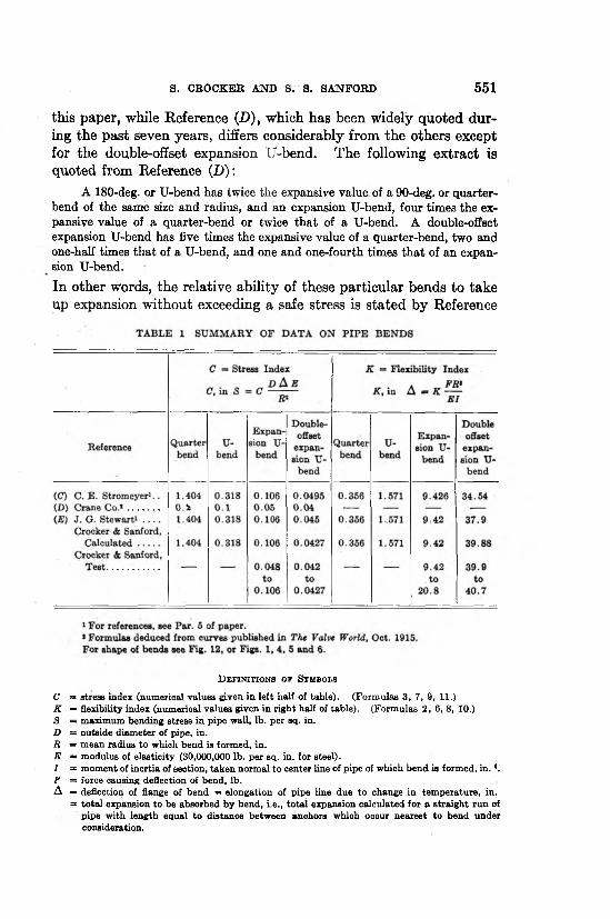
12 Table 1 is a summary of such data published in the above references as were in shape to reduce to a common form for comparison with the work of the present authors. I t will be noted that the formulas of References (C) and (E) agree very closely with those of
S. CROCKER AND S. S. SANFORD 5 5 1
this paper, while Reference (D), which has been widely quoted during the past seven years, differs considerably from the others except for the double-offset expansion U-bend. The following extract is quoted from Reference (D):
A 180-deg. or U-bend has twice the expansive value of a 90-deg. or quarter- bend of the same size and radius, and an expansion U-bend, four times the expansive value of a quarter-bend or twice that of a U-bend. A double-offset expansion U-bend has five times the expansive value of a quarter-bend, two and one-half times that of a U-bend, and one and one-fourth times that of an expansion U-bend.
In other words, the relative ability of these particular bends to take up expansion without exceeding a safe stress is stated by Reference
D e f i n i t i o n s o f S y m b o l s
C =» stress index (numerical values given in left half of table). (Form ulas 3, 7, 9, 11.)K * flexibility index (numerical values given in righ t half of table). (Form ulas 2, 6, 8, 10.)S = maximum bending stress in pipe wall, lb. per sq. in.D = outside diam eter of pipe, in.R = m ean radius to which bend is formed, in.E = modulus of elasticity (30,000,000 lb. per sq. in. for steel).I = m om ent of inertia of section, taken norm al to center line of pipe of which bend is formed, i n .4. F = force causing deflection of bend, lb.A = deflection of flange of bend = elongation of pipe line due to change in tem perature, in.
= to ta l expansion to be absorbed by bend, i.e., to ta l expansion calculated for a s tra igh t run of pipe with length equal to distance between anchors which occur nearest to bend under consideration.
5 5 2 ELASTICITY OF PIPE BENDS
(D) to be in the ratio of 1 : 2 : 4 : 5, while the calculated ratio given by References (C) and (E), and checked by the present authors, is1 : 4.4 : 13.2 :32.9, assuming that the quarter-bend is connected to the pipe line so that the thrust of the line acts along the axis of the pipe in the bend at the joint, as shown in Fig. 1.
13 Referring to the stress index of Table 1, Reference (D) agrees quite closely with the others’ results for double-offset expansion U-bends, but gives much higher values for the expansion cared for by quarter-bends, U-bends, and expansion U-bends than do the others. I t will also be noted that the stress and flexibility indexes for the double-offset expansion U-bend given by Reference (E) differ slightly from those given by the present authors. This is because the two bends considered are not of exactly the same shape.
14 A peculiarity of bends noted in Reference (A) was also observed in some of the bends tested by the authors, i.e., th a t the elasticity found by test exceeded the computed elasticity. Reference (A) describes tests on three kinds of bends formed to a shape which resembles a double-offset expansion U-bend, the first variety being bent from solid rod stock, the second from steel pipe, while the third was a hollow iron casting similar to a pipe bend. Tests of the first and third varieties checked very closely with calculated results, while the bend fabricated from a straight length of pipe was found to be much more elastic than the calculations indicated. The explanation given in Reference (A) is as follows:
We therefore establish:(1) That for the solid lyre-shaped bends a satisfactory conformity of cal
culated and measured value can be demonstrated.(2) That, on the contrary, for the lyre-shaped pipe the actual deflection was
very much greater than the calculated value.In addition to the reasons cited, which result in a difference between
measured and calculated results the slight effect of which was demonstrated in the experiments with solid bends, there must exist a further reason, peculiar to the conditions which obtain in the pipe, to which the very great difference in measured and calculated value can be attributed.
It can be deduced from the sketch of the test piece (a double-offset expansion U-bend), that it has deep waves or folds on the inner sides of the bends, that is, on the sides subjected to compression in the manufacture of the bend, these folds originating during the bending of the particular pipe length from which the bend is manufactured.
It is clear that the pipe bends which have these waves must possess much less resistance to the compressive forces which they have to withstand than would a smooth pipe bend without such waves. The waves or folds, by reason of their great number, will operate in an elastic manner despite their infinitely small depth; this must result in a very much greater total deflection of the bend
S. CROCKER AND S. S. SANFORD 5 5 3
than indicated by calculation, which of course assumes a pipe with smooth walls. If this view is correct, the phenomenon of the great elastic deflection of the expansion bends is in perfect accord with the purpose for which such an expansion bend is placed in long steam lines, and the greater elasticity yielded by the above- mentioned waves should be regarded as a valuable property possessed by the expansion bend.
In order to determine by experiment the correctness of the assumption regarding the effect of the waves — to prove it by calculation would necessitate very complicated and involved equations of little value — a cast-iron lyre-shaped pipe was made in which the waves or folds on the compressed side of the bend were absent. The pipe, of about 200 mm. (7.87 in.) inside diameter and about 18 mm. (0.7 in.) wall thickness, had the same bend radius as the steel pipe. It was furnished by Sulzer Bros., Winterthur, and represented an outstanding example of foundry technique when we consider the difficulty presented by the production of a test bend of this complicated design and of such dimensions. The deflections of this cast-iron pipe were determined by the same method and by the same equations as were employed in the case of the steel pipe.
From these experiments with the cast-iron pipes, together with those conducted with the solid steel lyre-shaped bodies, we are led to conclude that the large deflections of the steel pipes must be attributed chiefly to waves or folds upon the compressed side of the pipe.
15 This conclusion is supported by the results presented here, all of the test bends formed to a radius of five pipe diameters or less having a flexibility in excess of calculated values, while, with one exception, those formed to a radius of six diameters or more gave results agreeing closely with those obtained by the formulas. This would seem to indicate that the excessive elasticity was due to puckers or folds in the pipe wall produced in the process of bending, the tendency being to thin the pipe wall a t the outer circumference of the bend and form minute crinkles or waves a t the inner circumference. These conditions are more pronounced the shorter the radius of curvature, and in the case of the bend described in Reference (A), which was bent to a radius of only three to four pipe diameters, the waves were plainly visible. In American practice, where the minimum allowable radius of curvature is limited to five or six pipe diameters, these waves are not so visibly evident, nevertheless we may assume that they are present and have the effect of increasing the flexibility of bends formed to too short a radius.
M A T H E M A T IC A L A N A L Y S IS
16 A pipe bend may be considered as a beam of special form, one end of which is fixed and the other end of which is free to move in the direction of a force acting upon it. Since the bend is an elastic
5 5 4 ELASTICITY OF PIPE BENDS
body, the movement of its free end will be proportional to the force acting, within the elastic limit of the material.
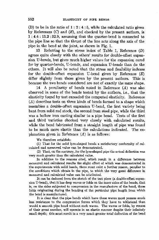
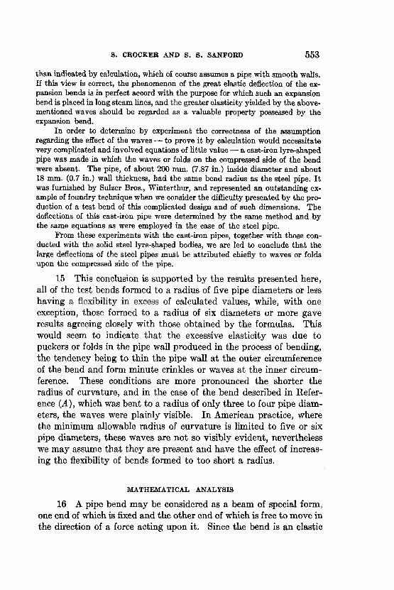
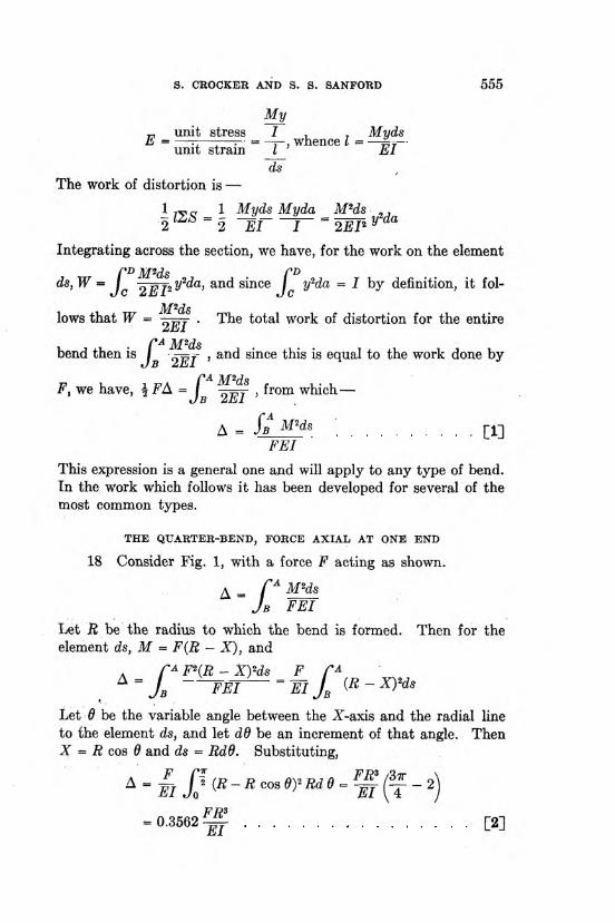
17 Consider any pipe bend, as in Fig. 1, showing a quarter- bend, with force F acting as shown. Flange A 'is fixed; flange B is free to move in the direction in which the force is acting. Let A be the total deflection of flange B measured in the direction of F, and caused by the force as it changes from 0 to F; then, considering the problem on an energy basis, the total work done by F will be 1-FA,
or the average force times the distance moved. The work done by F is also equal to the internal work of distortion in the bend. To obtain an expression for the work of distortion, consider an element of the bend of length .ds (Figs. 1 and 2). Let M = bending moment a t this section. The unit bending stress S existing at a distance y from the neutral axis N-N is M y / 1 ,1 being the moment of inertia of the section. The total stress 2<S on a fiber of cross-section da located a t this distance from the neutral axis is Myda/I. Let I be the elongation of this fiber and E the modulus of elasticity; then —
5 5 6 ELASTICITY OF PIPE BENDS
19 The maximum bending stress existing in the pipe wall of the bend for a given deflection may be derived from this expression. As before, the unit stress existing at a distance y from the neutral axis of the pipe is M y/I . Let D = outside diameter of the pipe, then since the greatest stress in any section occurs a t the outermost fiber, the unit stress S a t this point equals MD/2I. For the quarter bend the maximum moment occurs a t A, where M = FR, so the maximum stress S = FRD/2I . From the deflection formula
I t is obvious that for a given value of A the maximum fiber stress is proportional to the outside diameter of the pipe from which the bend
is made and that it is independent of the thickness of the pipe wall, i.e., the “weight” of the pipe. This will be found true for all cases considered.
THE QUARTER-BEND, FORCE PERPENDICULAR
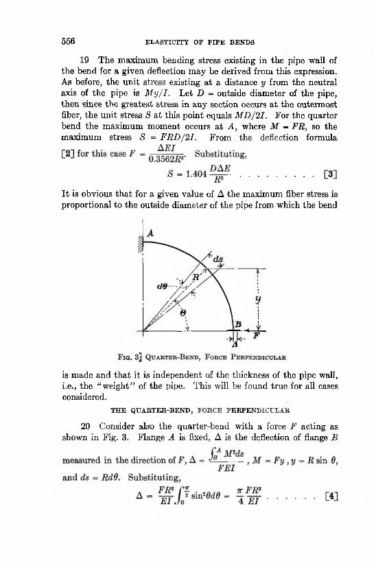
20 Consider also the quarter-bend with a force F acting as shown in Fig. 3. Flange A is fixed, A is the deflection of flange B
S. CROCKER AND S. , S. SANFORD 5 5 7
For a given deflection the maximum unit bending stress S in the quarter-bend occurs at A. S = M B/21 = FRD/2I, and from the deflection formula [4] F = iA E I / i rR 3. Substituting,
T H E U -B E N D
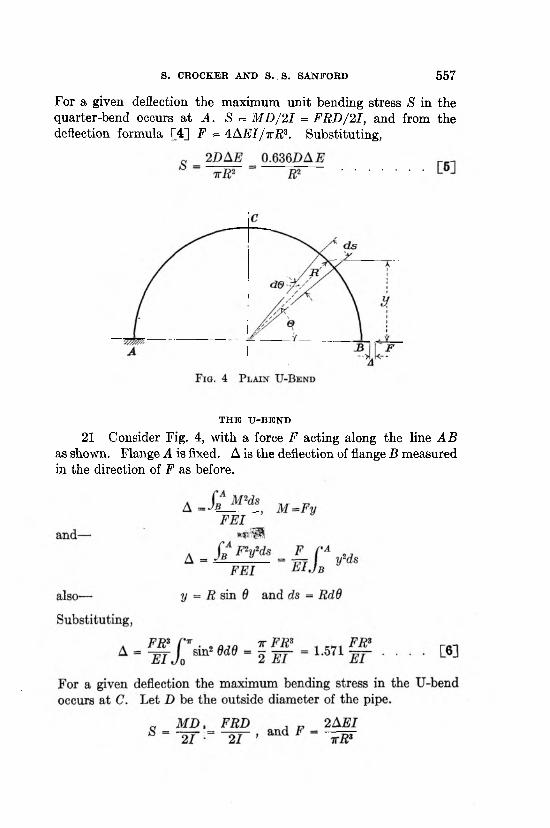
21 Consider Fig. 4, with a force F acting along the line A B as shown. Flange A is fixed. A is the deflection of flange B measured in the direction of F as before.
5 5 8 ELASTICITY OF PIPE BENDS
Substituting,
T H E E X P A N S IO N TJ-B E N D
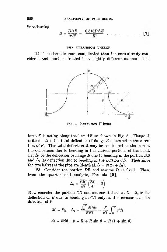
22 This bend is more complicated than the ones already considered and must be treated in a slightly different manner. The
force F is acting along the line A B as shown in Fig. 5. Flange A
tion of F. This total deflection A may be considered as the sum of the deflections due to bending in the various portions of the bend. Let Ai be the deflection of flange B due to bending in the portion DB and A2 its deflection due to bending in the portion CD. Then since the two halves of the pipe are identical, A = 2(Ai + A2).
23 Consider the portion DB and assume D as fixed. Then, from the quarter-bend analysis, Formula [2],
Now consider the portion CD and assume it fixed at C. A2 is the deflection of B due to bending in CD only, and is measured in the direction of F.
F ig . 5 E x p a n s io n U -B e n d
is fixed. A is the total deflection of flange B measured in the direc-
S. CROCKER AND S. « . SANFORD 5 5 9
24 The maximum unit bending stress S in the expansion U- bend occurs a t C. Let D be the outside diameter of the pipe,
T H E D O U B L E -O F F S E T E X P A N S IO N U -B E N D
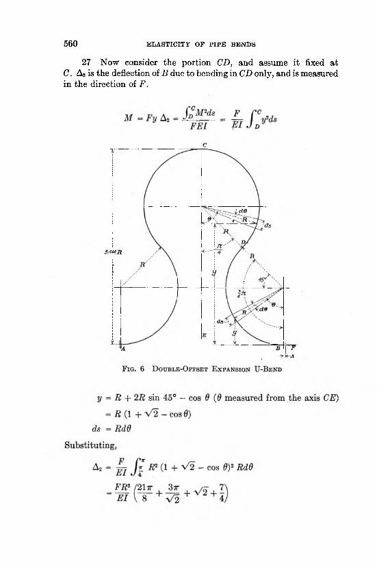
25 The analysis for this bend is similar to that for the expansion U-bend. Force F acts as shown in Fig. 6, along the line AB. Flange A is fixed. A is the total deflection of flange B measured in the direction of F. Let Ai = deflection of flange B due to bending in the portion DB and A2 its deflection due to bending in the portion CD. Then A = 2(Ai + A2) as before.
26 Consider the portion DB and assume D as fixed.
5 6 0 ELASTICITY OF PIPE BENDS
27 Now consider the portion CD, and assume it fixed at C. A2 is the deflection of B due to bending in CD only, and is measured in the direction of F.
S. CROCKER AND S. ,S . SANFORD 5 6 1
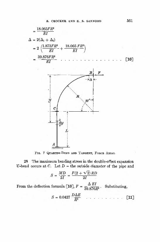
F ig . 7 Q u a k t e r -B e n d a n d T a n g e n t , F o b c e A x ia l
28 The maximum bending stress in the double-offset expansion TJ-bend occurs a t C. Let D = the outside diameter of the pipe and
5 6 2 ELASTICITY OF PIPE BENDS
QUARTER-BEND AND TANGENT, FORCE AXIAL
29 Consider Fig. 7, with force F acting as shown. Flange A is fixed. Let A be the total deflection of flange B, measured in the direction of F. Let Ai be the deflection of flange B due to bending in the portion CB, and A2 the deflection due to bending in the portion AC. Then A = Ax + A2.
30 If we consider C as fixed, then from the quarter-bendF R 3
analysis formula [2], Ai = 0.3562 -=rr.til
31 Now consider the portion AC of length L and assume it fixed at A. A2 is the deflection of B due to bending in AC only, and is measured in the direction of F.
a f c '4 M H s 2 FEI
The element dy is a t a distance y from the line of action of the force F, M = Fy, and ds = dy. Substituting,
Q U A R T E R -B E N D A N D T A N G E N T , F O R C E P E R P E N D IC U L A R
33 Consider Fig. 8 with force F acting as shown, parallel to AC. Flange A is fixed. Let A be the total deflection of flange B, measured in the direction of F. Let Ax be the deflection of the flange B due to bending in the portion CB and A2 the deflection due to bending in the portion AC, then A = Ax + A2.
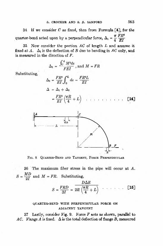
34 If we consider C as fixed, then from Formula [4], for the7T FRSquarter-bend acted upon by a perpendicular force, Ax = —4 h i i
35 Now consider the portion AC of length L and assume it fixed at A. A2 is the deflection of B due to bending in AC only, and is measured in the direction of F.
S. CROCKER AND S. £ . SANFORD 5 6 3
QUARTER-BEND W ITH PERPENDICULAR FORCE ON ADJACENT TANGENT
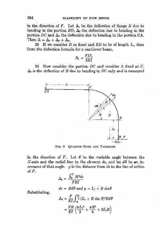
37 Lastly, consider Fig. 9. Force F acts as shown, parallel to AC. Flange A is fixed. A is the total deflection of flange B, measured
5 6 4 ELASTICITY OF PIPE BENDS
in the direction of F. Let Ai be the deflection of flange B due to bending in the portion BD, A2 the deflection due to bending in the portion DC and A3 the deflection due to bending in the portion CA. Then A — Ai -f- A2 -I- A3.
38 If we consider D as fixed and BD to be of length L u then from the deflection formula for a cantilever beam,
A1 3 E l
39 Now consider the portion DC and consider it fixed at C. A2 is the deflection of B due to bending in DC only and is measured
in the direction of F. Let 8 be the variable angle between the X-axis and the radial line to the element ds, and let dd be an increment of tha t angle, y is the distance from ds to the line of action
S. CROCKER AND S .' S. SANFORD 5 6 5
GENERAL
41 In like manner the formula for any shape of bend that the designer may use can be derived from the fundamental equation
CM2dsA = by considering the bend a section a t a time. The
method of attack should be clear from the foregoing.42 In each case which has been taken up, flange A has been
considered as fixed. Such a condition would exist if the line to which A is connected were anchored a t that point, or if A were a flange at the turbine. As a m atter of fact, the entire analysis is really based on the movement of flange B with respect to A , and it makes no difference whether A is actually fixed or is permitted to move. F is the net force with which the pipe line pushes against the flange B when the line is hot. Such cases as pictured in Figs. 3, 4, 8 and 9, where the pipe line is represented as pushing at right angles to the pipe in the bend, are encountered when the fitting at B is a tee, a cross or
5 6 6 ELASTICITY OF PIPE BENDS
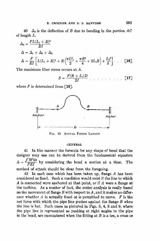
a short-radius ell." For design purposes the total expansion to be cared for between anchorages is determined from known or assumed temperatures, length of pipe, and coefficient of linear expansion. The length of pipe used is a nominal length equal to the actual linear distance between anchorages. In effect, it is as though a line of pipe such as that shown in Fig. 10 were assumed to be like that in Fig. 11, with the total movement due to the expansion of a straight pipe of length L applied at the flange B.
D E S IG N G R A P H S
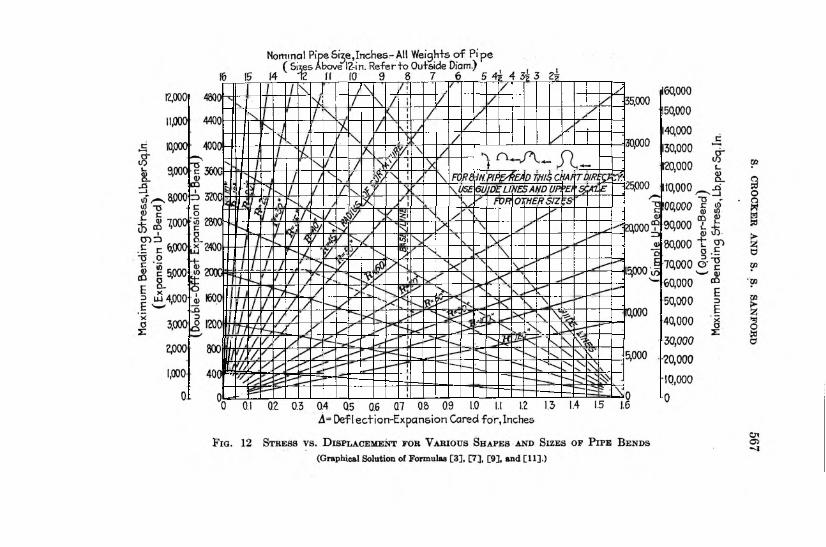
43 For the convenience of the power-plant designer, the formulas for several of the standard bends are represented graphically in Figs. 12, 13 and 14. The bends considered are the quarter-bend, U-bend, expansion U-bend, and double-offset expansion U-bend with the forces applied as shown in the small figures on the graph and corresponding to Figs. 1, 4, 5 and 6. The forces and stresses set up in bends made up of pipe sizes up to and including 20 in., and bent to radii up to and including 120 in., may be read from these graphs without the necessity of solving the formulas.
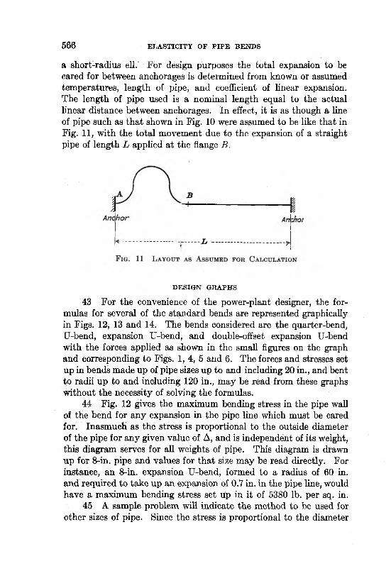
44 Fig. 12 gives the maximum bending stress in the pipe wall of the bend for any expansion in the pipe line which must be cared for. Inasmuch as the stress is proportional to the outside diameter of the pipe for any given value of A, and is independent of its weight, tins diagram serves for all weights of pipe. This diagram is drawn up for 8-in. pipe and values for th a t size may be read directly. For instance, an 8-in. expansion U-bend, formed to a radius of 60 in. and required to take up an expansion of 0.7 in. in the pipe line, would have a maximum bending stress set up in it of 5380 lb. per sq. in.
45 A sample problem will indicate the method to be used for other sizes of pipe. Since the stress is proportional to the diameter
S. CROCKER AND S. S . SANFORD 5 6 9
of the pipe, the value of the stress for any size of pipe may be obtained after finding the stress in an 8-in. pipe. The proportion between stresses can be made directly on the diagram by following the radial lines diverging from its lower right corner.
S a m p le P r o b l e m : A 12-in. double-offset expansion U-bend having a radius of 90 in. is to take up an expansion of 1 in. Required, the maximum bending stress in the bend.
From the intersection of A = 1 in. and R = 90 in., extend horizontally to the vertical line under 8-in. pipe, which is referred to as the “ base line,” and then obliquely (with a line passing through lower right-hand comer) until under 12-in. pipe on the upper scale. The result is 2040 lb. per sq. in.
46 Since the stress is directly proportional to the displacement, this diagram may be used for values of A which fall beyond its range by multiplying both stress and displacement scales by the same factor. For instance, if a 5-in. expansion is to be considered, the stress for an expansion of 1 in. should be read on the graph and multiplied by 5.
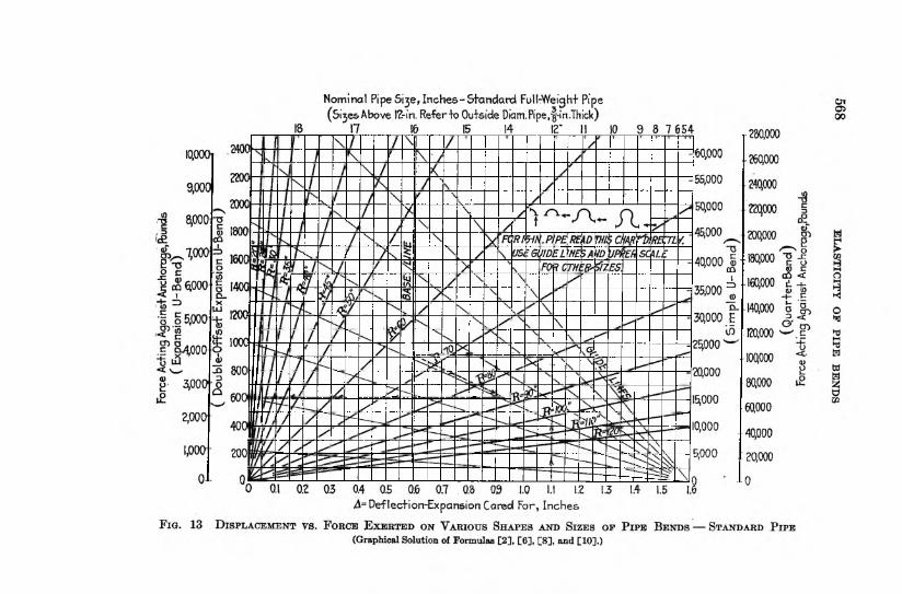
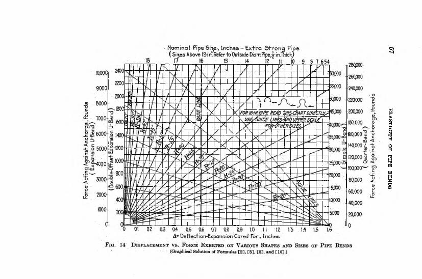
47 Figs. 13 and 14 give the forces set up in the pipe line when pipe bends are used to take up the expansion. As these relations are functions of the moments of inertia of the pipe sections, the internal diameters affect the results, and Fig. 13 has been drawn for “ standard weight” and Fig. 14 for “ extra heavy” pipe. These diagrams are for 16-in. pipe and values for this size may be read directly. The scale of pipe sizes a t the top of diagram is laid off according to the moment of inertia of the pipe section, as the force to produce a given deflection in the bend is proportional not to the diameter, but to the moment of inertia of the pipe.
48 After finding the force existing for a given deflection in the 16-in. pipe, the value for any other size of pipe may be obtained by using the radial lines diverging from the lower right comer, and the vertical base line under 16-in. pipe, for making the proportion. The solution for a sample problem is indicated by the dash lines in Fig. 13. A double-offset expansion U-bend made of 14-in. O.D. pipe, f in. thick, formed to a radius of 80 in., is required to take up an expansion of 1.1 in. in the pipe line. From the diagram, the force acting against the pipe anchorage is 610 lb.
49 Since the force is directly proportional to the displacement, these diagrams also may be used for values which fall beyond their range by considering both force and displacement scales as multiplied by the same factor. I t should be noted that in using these
Cn
ELASTICITY
OP
PIPE B
EN
DS
S. CROCKER AND ft. S. SANFORD 571
diagram s the pipe size refers to the size of pipe used in the bend and has nothing to do w ith the size of pipe in the rest of the line.
M E T H O D O F T E S T
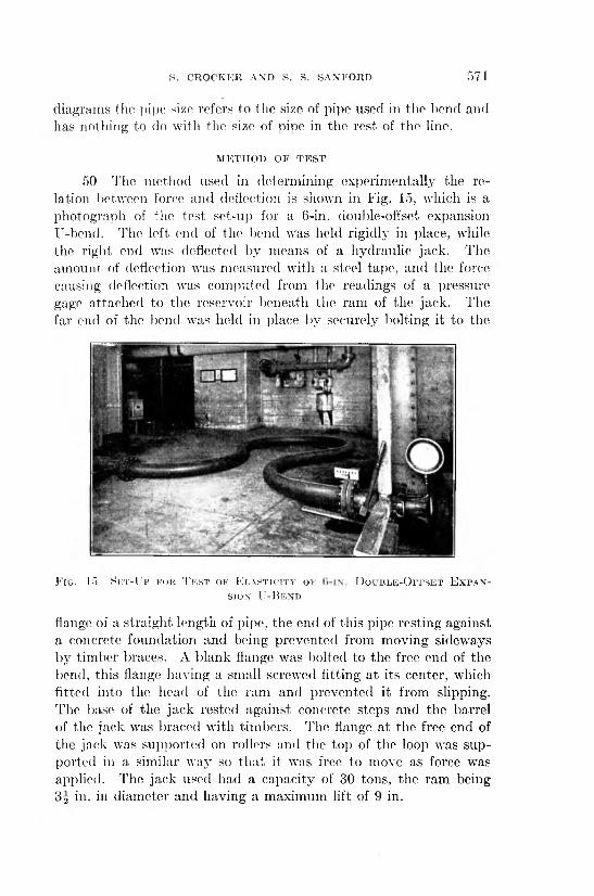
50 T he m ethod used in determ ining experim entally the relation betw een force and deflection is shown in Fig. 15, which is a photograph of the te s t set-up for a 6-in. double-offset expansion U-bend. The left end of the bend was held rigidly in place, while the righ t end was deflected by m eans of a hydraulic jack. The am ount of deflection was m easured w ith a steel tape, and the force causing deflection was com puted from the readings of a pressure gage a ttached to the reservoir beneath the ram of the jack. The far end of the bend was held in place by securely bolting it to the
F ig . 15 S e t - U p f o k T k s t o f E l a s t i c i t y o f D o u b l e - O f f s e t E x p a n s i o n ' U - B e n d
flange of a stra igh t length of pipe, th e end of th is pipe resting against a concrete foundation and being p revented from m oving sideways by tim ber braces. A b lank flange was bolted to the free end of the bend, th is flange having a sm all screwed fitting a t its center, which fitted into the head of the ram and p revented it from slipping. T he base of the jack rested against concrete steps and the barrel of the jack was braced w ith tim bers. The flange a t the free end of the jack was supported on rollers and the top of the loop was supported in a sim ilar way so th a t it was free to m ove as force was applied. T he jack used had a capacity of 30 tons, the ram being3 2 in. in d iam eter and having a m axim um lift of 9 in.
572 ELASTICITY OF PIPE BENDS
51 T he pressure required to overcome in itia l friction before an y m ovem ent of th e bend took place, was determ ined roughly by ligh tly wedging th e po in t of a pencil betw een th e m ovable head and th e s ta tio n ary barre l of th e jack, so th a t i t was supported horizontally , and th en carefully pum ping the jack and noting the pressure a t which th e pencil was released, a very slight m ovem ent of the head being sufficient to le t the pencil fall. Before th e gage pressure was recorded the end of the bend was jo lted up and down so as to relieve any binding action th a t m ight be present.
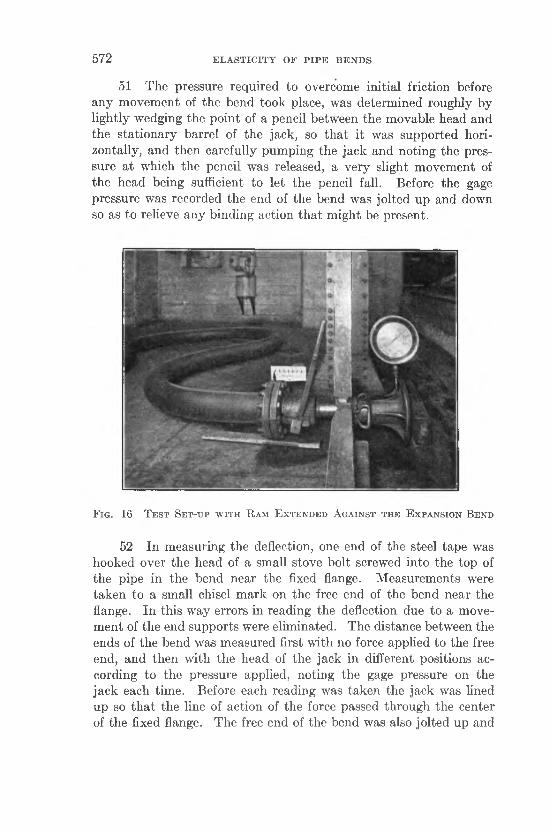
F i g . 16 T e s t S e t - u p w i t h R a m E x t e n d e d A g a in s t t h e E x p a n s i o n B e n d
52 In m easuring the deflection, one end of the steel tape was hooked over th e head of a sm all stove bolt screwed in to the top of th e pipe in th e bend near th e fixed flange. M easurem ents were tak en to a sm all chisel m ark on the free end of the bend n ear the flange. In th is w ay errors in reading the deflection due to a m ovem en t of th e end supports were elim inated. T he distance betw een the ends of th e bend was m easured first w ith no force applied to the free end, and th en w ith th e head of the jack in different positions according to the pressure applied, no ting th e gage pressure on the jack each tim e. Before each reading was tak en th e jack was lined up so th a t th e line of action of the force passed th rough the center of the fixed flange. T he free end of the bend was also jo lted up and
S. CROCKER AND S.- S. SANFORD 5 7 3
down before each reading, to relieve any binding action. Care was taken not to use forces which would stress the' material a t the top of the loop beyond its elastic limit. The ram was pushed out to almost the elastic limit of the pipe material and released several times for each bend, as many intermediate readings as possible being taken each time.
53 The only bends tested were expansion U-bends and doubleoffset expansion U-bends, because these shapes were easy to sup-
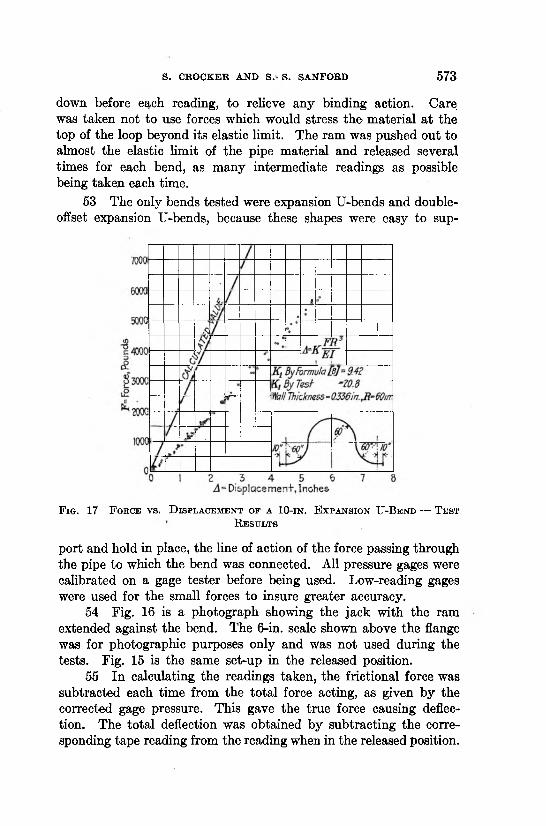
F ig . 17 F o r c e v s . D is p l a c e m e n t o f a 10-i n . E x p a n s io n U -B e n d — T e s t
R e s u l t s
port and hold in place, the line of action of the force passing through the pipe to which the bend was connected. All pressure gages were calibrated on a gage tester before being used. Low-reading gages were used for the small forces to insure greater accuracy.
54 Fig. 16 is a photograph showing the jack with the ram extended against the bend. The 6-in. scale shown above the flange was for photographic purposes only and was not used during the tests. Fig. 15 is the same set-up in the released position.
55 In calculating the readings taken, the frictional force was subtracted each time from the total force acting, as given by the corrected gage pressure. This gave the true force causing deflection. The total deflection was obtained by subtracting the corresponding tape reading from the reading when in the released position.
5 7 4 ELASTICITY OF PIPE BENDS
R E S U L T S O F T E S T S
56 In all, eight separate expansion bends were tested. The results are given in detail in Figs. 17 to 24, inclusive, and in condensed form in Table 2.
57 As noted before, the results from bends formed to a radius greater than 5 pipe diameters agreed closely with those obtained
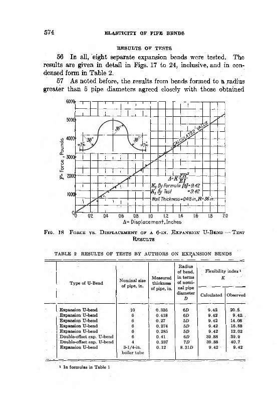
F ig . 18 F o r c e v s . D is p l a c e m e n t o f a 6 - i n . E x p a n s io n U -B e n d — T e s t
R e s u l t s
S. CROCKER AND S. S. SANFORD 5 7 5
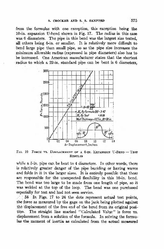
from the formulas with one exception, this exception being the 10-in. expansion U-bend shown in Fig. 17. The radius in this case was 6 diameters. The pipe in this bend was the largest size tested, all others being 6-in. or smaller. I t is relatively more difficult to bend large pipe than small pipe, so as the pipe size increases the minimum allowable radius (expressed in pipe diameters) also has to be increased. One American manufacturer states that the shortest radius to which a 22-in. standard pipe can be bent is 6 diameters,
F i g . 19 F o r c e v s . D is p l a c e m e n t o f a 6 - i n . E x p a n s i o n U - B e n d — T e s t
R e s u l t s
while a 5-in. pipe can be bent to 4 diameters. In other words, there is relatively greater danger of the pipe buckling or having waves and folds in it in the larger sizes. I t is entirely possible that these are responsible for the unexpected flexibility in this 10-in. bend. The bend was too large to be made from one length of pipe, so it was welded at the top of the loop. The bend was one purchased especially for test and had not seen service.
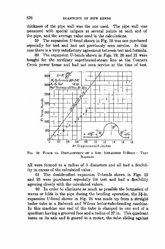
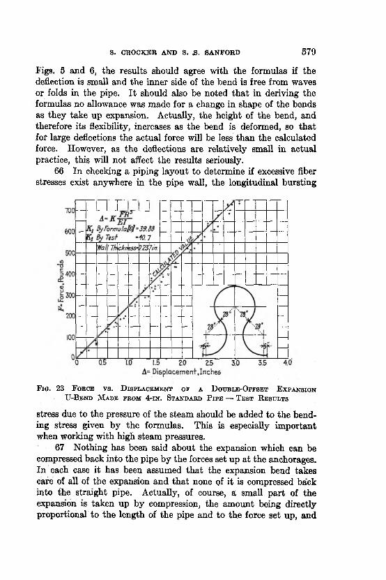
58 In Figs. 17 to 24 the dots represent actual test points, the force as measured by the gage on the jack being plotted against .the displacement of the free end of the bend from its original position. The straight line marked “ Calculated Value” is force vs. displacement from a solution of the formula. In solving the formulas the moment of inertia as calculated from the actual measured
5 7 6 ELASTICITY OF PIPE BENDS
thickness of the pipe wall was the one used. The pipe wall was measured with special calipers a t several points a t each end of the pipe, and the average value used in the calculations.
59 The expansion U-bend shown in Fig. 18 was one purchased especially for test and had not previously seen service. In this case there is a very satisfactory agreement between test and formula.
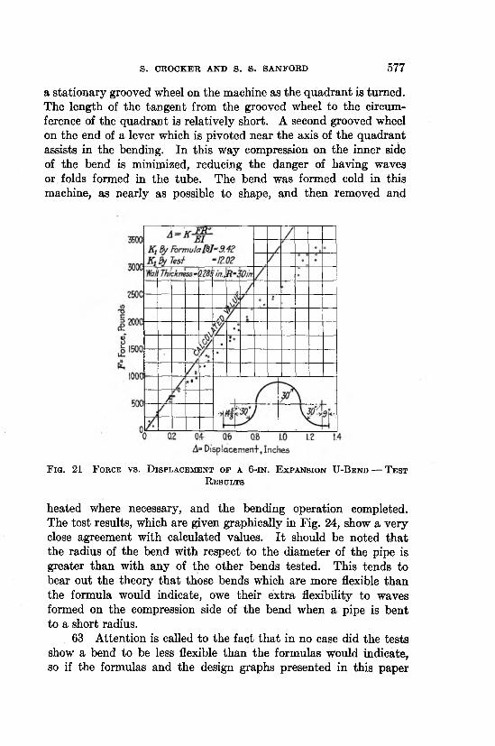
60 The expansion U-bends shown in Figs. 19, 20 and 21 were bought for the auxiliary superheated-steam line a t the Connors Creek power house and had not seen service at the time of test.
F i g . 20 F o r c e v s . D is p l a c e m e n t o f a 6 - i n . E x p a n s i o n U - B e n d — T e s t
R e s u l t s
All were formed to a radius of 5 diameters and all had a flexibility in excess of the calculated value.
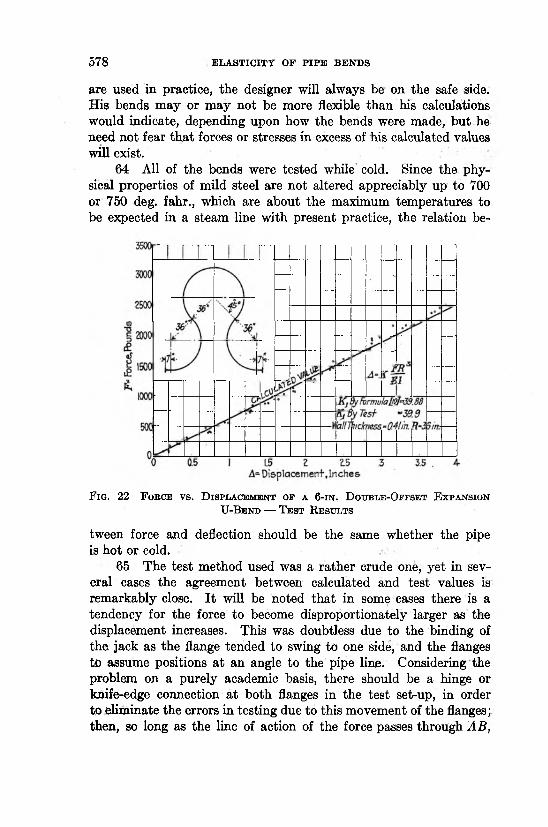
61 The double-offset expansion U-bends shown in Figs. 22 and 23 were purchased especially for test and had a flexibility agreeing closely with the calculated values.
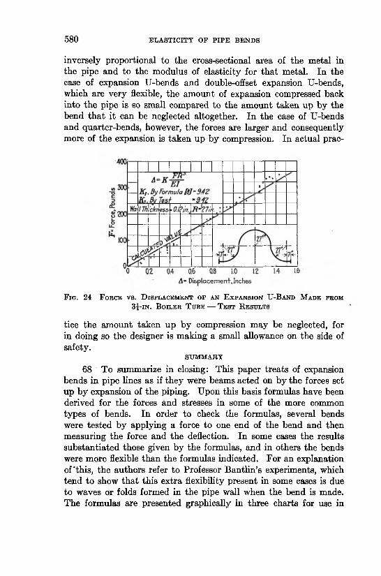
62 In order to eliminate as much as possible the formation of waves or folds in the pipe during the bending operation, the 3J-in. expansion U-bend shown in Fig. 24 was made up from a straight boiler tube in a Babcock and Wilcox boiler-tube-bending machine. In this machine one end of the tube is clamped to one end of a quadrant having a grooved face and a radius of 27 in. This quadrant turns on its axis and is geared to a motor, the tube sliding against
S. CROCKER AND S. S. SANFOBD 5 7 7
a stationary grooved wheel on the machine as the quadrant is turned. The length of the tangent from the grooved wheel to the circumference of the quadrant is relatively short. A second grooved wheel on the end of a lever which is pivoted near the axis of the quadrant assists in the bending. In this way compression on the inner side of the bend is minimized, reducing the danger of having waves or folds formed in the tube. The bend was formed cold in this machine, as nearly as possible to shape, and then removed and
F i g . 21 F o r c e v s . D i s p l a c e m e n t o f a 6 - i n . E x p a n s i o n U - B e n d — T e s t
R e s u l t s
heated where necessary, and the bending operation completed. The test results, which are given graphically in Fig. 24, show a very close agreement with calculated values. I t should be noted that the radius of the bend with respect to the diameter of the pipe is greater than with any of the other bends tested. This tends to bear out the theory tha t those bends which are more flexible than the formula would indicate, owe their extra flexibility to waves formed on the compression side of the bend when a pipe is bent to a short radius.
63 Attention is called to the fact that in no case did the tests show a bend to be less flexible than the formulas would indicate, so if the formulas and the design graphs presented in this paper
5 7 8 ELASTICITY OF PIPE BENDS
are used in practice, the designer will always be on the safe side. His bends may or may not be more flexible than his calculations would indicate, depending upon how the bends were made, but he need not fear that forces or stresses in excess of his calculated values will exist.
64 All of the bends were tested while cold. Since the physical properties of mild steel are not altered appreciably up to 700 or 750 deg. fahr., which are about the maximum temperatures to be expected in a steam line with present practice, the relation be-
F ig . 22 F o b c e v s . D is p l a c e m e n t o f a 6 - i n . D o u b l e -O f f s e t E x p a n s io n TJ-Be n d — T e s t R e s u l t s
tween force and deflection should be the same whether the pipe is hot or cold.
65 The test method used was a rather crude one, yet in several cases the agreement between calculated and test values is remarkably close. I t will be noted that in some cases there is a tendency for the force to become disproportionately larger as the displacement increases. This was doubtless due to the binding of the jack as the flange tended to swing to one side, and the flanges to assume positions a t an angle to the pipe line. Considering the problem on a purely academic basis, there should be a hinge or knife-edge connection a t both flanges in the test set-up, in order to eliminate the errors in testing due to this movement of the flanges; then, so long as the line of action of the force passes through AB,
S. CROCKER AND S. 3 - SANFORD 5 7 9
Figs. 5 and 6, the results should agree with the formulas if the deflection is small and the inner side of the bend is free from waves or folds in the pipe. I t should also be noted tha t in deriving the formulas no allowance was made for a change in shape of the bends as they take up expansion. Actually, the height of the bend, and therefore its flexibility, increases as the bend is deformed, so that for large deflections the actual force will be less than the calculated force. However, as the deflections are relatively small in actual practice, this will not affect the results seriously.
66 In checking a piping layout to determine if excessive fiber stresses exist anywhere in the pipe wall, the longitudinal bursting
F ig . 23 F o b c e v s . D i s p l a c e m e n t o f a D o u b l e - O f f s e t E x p a n s io n U -B e n d M a d e f k o m 4 - in . S t a n d a r d P ip e — T e s t R e s u l t s
stress due to the pressure of the steam should be added to the bending stress given by the formulas. This is especially important when working with high steam pressures.
67 Nothing has been said about the expansion which can be compressed back into the pipe by the forces set up a t the anchorages. In each case it has been assumed that the expansion bend takes cafe of all of the expansion and tha t none of it is compressed back into the straight pipe. Actually, of course, a small part of the expansion is taken up by compression, the amount being directly proportional to the length of the pipe and to the force set up, and
5 8 0 ELASTICITY OF PIPE BENDS
inversely proportional to the cross-sectional area of the metal in the pipe and to the modulus of elasticity for that metal. In the case of expansion U-bends and double-offset expansion U-bends, which are very flexible, the amount of expansion compressed back into the pipe is so small compared to the amount taken up by the bend tha t it can be neglected altogether. In the case of U-bends and quarter-bends, however, the forces are larger and consequently more of the expansion is taken up by compression. In actual prac-
F ig . 24 F o r c e v s . D is p l a c e m e n t o f a n E x p a n s io n U -B a n d M a d e fr o m 3 j - i n . B o il e r T u b e — T e s t R e s u l t s
tice the amount taken up by compression may be neglected, for in doing so the designer is making a small allowance on the side of safety.
SUMMARY
68 To summarize in closing: This paper treats of expansion bends in pipe lines as if they were beams acted on by the forces set up by expansion of the piping. Upon this basis formulas have been derived for the forces and stresses in some of the more common types of bends. In order to check the formulas, several bends were tested by applying a force to one end of the bend and then measuring the force and the deflection. In some cases the results substantiated those given by the formulas, and in others the bends were more flexible than the formulas indicated. For an explanation of'this, the authors refer to Professor Bantlin’s experiments, which tend to show that this extra flexibility present in some cases is due to waves or folds formed in the pipe wall when the bend is made. The formulas are presented graphically in three charts for use in
DISCUSSION 5 8 1
selecting the proper shape and size of bend to take up a given expansion. In the light of the material presented in this paper the limits of safe expansion values for pipe bends set by Reference (D), and commonly quoted in engineering texts and handbooks, are apparently correct only for the double-offset expansion U-bend. For the other shapes the published values are much in excess of those given here. I t is the authors’ contention tha t these limits should be revised to agree with the formulas presented in this paper, for unless the published tables are used with large factors of safety, the forces and stresses existing in pipe lines will be excessive and dangerous.
DISCUSSION
G e o r g e A. O r r o k said that he understood all the research had been made with cold pipe without pressure on the inside. He wondered if there was any difference between the action of the pipe bend with two or three hundred pounds pressure on the inside and that of one which was cold and unstressed.
J. A. F r e id a y , speaking as a representative of Thomas E. Murray, Inc., said that they considered the paper a valuable contribution bearing as it did upon a subject which had not always been given proper consideration in the past. The subject was one which they had carefully considered in the numerous power stations they had designed. Up to two or three years ago they had made use of expansion loops made of pipe bends similar to those described in the paper. In a few cases, he said, they had experienced trouble with bends which evidently had not been properly annealed and which showed a tendency to straighten out and grow after being placed in service. In one case the growth of a 14-in., 90-deg. bend exceeded2 in. in a few months, the increase being measured after the pipe had been taken out of the line.
In order to eliminate the possibility of such distortion and also to take care of the increasing steam temperatures in larger steam lines required by larger modern units, they had made an investigation some time ago to determine the best method of providing for expansion with the least reaction at the point of anchorage. The result of the investigation, he said, showed that loops corresponding to the expansion U-bends but made up of straight pipe and fittings produced less reaction than an expansion U-bend requiring the same space.
5 8 2 ELASTICITY OF P IP E BENDS
This method of taking care of bends, he said, lent itself particularly to large pipe, for the use of large expansion U-bends was not practical due to fabrication difficulties. With the design of loop they had used in all recent installations no excessive pressure drop had been encountered due to this method of making bends.
He asked the authors if they had investigated any loops designed as he had described. >
In making a comparison between the bend made up of straight pipe and fittings and the expansion loop bend, the following formulas were used. For the straight pipe type, the formula for the deflection of bends in Modern Frame Structures, Part 1, by Johnson, Bryan and Turneaure, was used. For the circular bends, the formulas used have been taken from the article by J. G. Stewart published in Power, May 10, 1921.
The calculations are based on the assumption tha t the ends are free to move, which necessitates locating anchors some distance from the bends. In making use of ells for the right angle turns, the deflection will be slightly reduced, but allowing for this it can easily be seen that a bend of this type is more flexible than the standard U-bend. The fiber stress in the ells will tend to increase on account of the short radius but as the body of the fittings is considerably heavier than the body of the pipe it can easily be proven that there is no possibility of rupture a t these points.
The comparative formulas1 follow:
If D = deflectionA = radius of bend in inches E = modulus of elasticity of materialS = maximum fiber stress, lb. per sq. in. d = outside diameter of pipe in inches
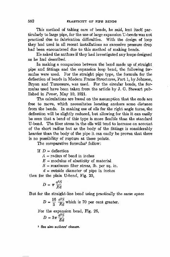
then for the plain U-bend, Fig. 25,
° - T mBut for the straight-line bend using practically the same space
_ 16 a?S , . , . , ,~Z ~Ed 1 ls Per cen>; greater.
For the expansion bend, Fig. 26,
1 See also authors’ closure.
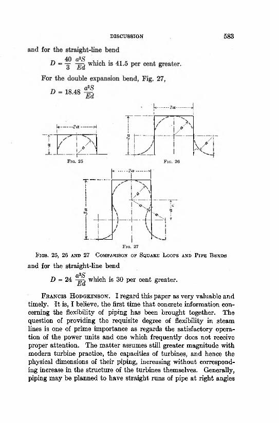
DISCUSSION 5 8 3
Fias. 25, 26 a n d 27 C o m p a r is o n o f S q u a r e L o o p s a n d P i p e B e n d s
and for the straight-line bend a2SD = 24 which is 30 per cent greater.
F r a n c is H o d g k in s o n . I regard this paper as very valuable and timely. I t is, I believe, the first time tha t concrete information concerning the flexibility of piping has been brought together. The question of providing the requisite degree of flexibility in steam lines is one of prime importance as regards the satisfactory operation of the power units and one which frequently does not receive proper attention. The m atter assumes still greater magnitude with modern turbine practice, the capacities of turbines, and hence the physical dimensions of their piping, increasing without corresponding increase in the structure of the turbines themselves. Generally, piping may be planned to have straight runs of pipe a t right angles
5 8 4 . ELASTICITY OP P IP E BENDS
to each other, and so secure a flexibility without the use of the elaborate bends described in the paper.
A valuable addition to the paper would have been some discussion of resistance of piping to torsional stresses, as it is sometimes difficult to arrange piping to give flexibility in every direction without recourse to its torsional elasticity.
The general arrangement of steam piping to power units demands careful thought, not only to provide against expansion of the piping due to heat, but that small misalignment of flange may be compensated for in every direction.
R o b e r t C r a m e r said tha t it was gratifying to learn that the authors had made an attem pt to compare directly theoretical and experimental results. He noted in the paper, however, a point of theoretical nature which should be considered when test results were compared with calculated results. In the diagram giving the basis of the theoretical investigation, Figs. 1 and 2, the neutral fiber of the cross-section of the bend was assumed to pass through the center of the circle which was not true in the case of a pipe bend. I t was a well-known fact, he said, that the neutral fiber in curved beams did not pass through the center of gravity of the cross-section as it did in straight beams, and the peculiarity was more pronounced the shorter the radius of the beam compared with the magnitude of the cross-section.
For this reason, he said, it would pay the authors to pursue a line of more rigid theoretical investigation of the deviation of the experimental results from the theoretical results in the case of the shorter bends. He said tha t he noted in making comparison between the experimental and calculated results that in some cases the two checked closely while in others the variation was very marked. I t was not the slight variation to be expected from experimental or observational errors but one which would suggest that the authors should look for some error in their calculations.
The authors considered the deflecting force always to be at right angles to the flange on which it was applied with the exception of the case of the quarter bend, in which they had distinguished between two cases, one with the force acting at right angles to the flange and the other with a force acting in the plane of the flange. In the actual case, he said, the problem was really more complicated than would appear from the authors’ investigation as it was frequently necessary to twist the flange in order to make a tight joint and this involved another source of strain.
DISCUSSION 5 8 5
W il l ia m B. C a m p b e l l . The right-hand half of the authors’ Table 1 gives data for direct comparison of the calculated relations between force F acting on the bend and the deflection A produced with the same relation from actual test. I t would appear, however, that the left-hand portion is semi-experimental, in tha t their calculated values show a relation deduced analytically between the observed deflection A and the maximum fiber stress S, while in the line giving “ tes t” results, S is manifestly not observed directly, but is inferred from the experimental value of F which accompanies a given A. This method of course reflects the observed relation between deflection and force acting, but it does not eliminate the effect of the method used for calculating S from F, which is based on ideal conditions in the shape and physical dimensions of the pipe. For this reason the “ experimental” data in this section are not so conclusive as those in the right-hand section.
H. L e R o y W h it n e y said he had noticed many examples of square bends and U-bends which did not take up the expansion they had been figured for and also, particularly in long transmission lines, he had noticed the double expansion U-bend had taken over twice the expansion figured for it and that over a period of years no marked deterioration in the pipe was shown. In regard to the buckling of pipe on the inside of the bend, he said that it was perfectly evident that if the pipe did buckle on the inside the fibers on the outside were not stressed nearly as much as if the pipe did not buckle. In large bends of comparatively small thickness it was almost impossible to make them without buckles on the inside. The buckles did no harm, he thought, and they did not retard the flow of steam through the pipe to any appreciable extent and did take up expansion. If the pipe was subject to very high vibrations, he said, it was sometimes customary to pull or push them to the full extent that they would be distorted by expansion so tha t when they were hot they would be in their normal state relieving the thrust on the steam apparatus.
S. T im o s h e n k o . The authors state that in some of the bends tested, the elasticity found by test exceeded the computed elasticity. Following the explanation given by A. Bantlin,1 the authors attribute the large deflexions to waves or folds upon the compressed side of the pipe.
1 Zeitschrift d. Vereines Deutscher Ingenieure, 1910, p. 43. See also: M it- teilungm uber Forschungsarbeiten, H eft 96.
5 8 6 ELASTICITY OF P IP E BENDS
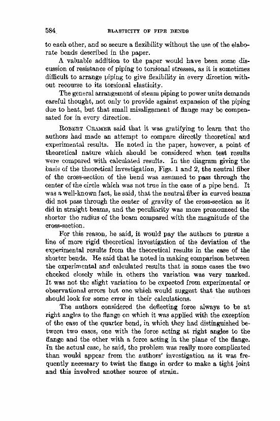
In the following, it is shown that the discrepancy between test results and calculations can be removed by taking account of the distortion of the cross-section of the pipe bends due to bending.1
Consider an element of the bend between two neighboring cross-sections ac and bd (Fig. 28). I t is easy to see, Fig. 28, that the tensile forces P a t the outer side of the bend, and the compressive forces Q a t the inner side give resultants T in the direction towards the neutral axis. As a result of this, the previously circular cross- sections become elliptical. Consider now what will be the effect of this distortion on the deformation of the longitudinal fibers of th e - bend. Let Q denote the initial small angle between the cross-sec
tions taken, 80 the small change of this angle a t bending. Let the outer fibre ab after bending take the position aj)\ and its small displacement towards the neutral axis be denoted b y /. The extension of the fiber is
I = aib j — ab = a J i — axci — (ab — a ^ ) . . . . [a]
Now, assuming that the neutral axis passes through the center of the cross-section, we obtain
aj)i — aiCi = cjbi - rddab - aiCj = (R + r)6 - (R + r - f)6 = fd
1 The problem of the distortion of the cross-section of circular pipes as solved by Th. K&rm&n. See his paper, Uber die Forman derung diinnwandiger Rohre, insbesondere federnder Ausgleiehrohre. Zeitschrifl d. Vereines Deutscher- Ingenieure, Bd. 55 (1911), p. 1889. From this paper are taken the Formulas [20] and [23] below. The case of a rectangular cross-section of curved pipes is considered in the author's paper to be presented at Spring Meeting of the Society to be held in Montreal, Canada, May 28-31.
DISCUSSION 5 8 7
Substituting this in [a] and dividing the extension I by the initial length of the fiber db, equal to (R + t)6, we obtain the unit elongation of the fiber as follows:
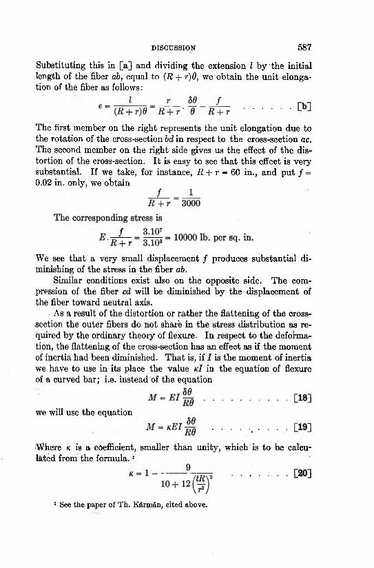
The first member on the right represents the unit elongation due to the rotation of the cross-section bd in respect to the cross-section ac. The second member on the right side gives us the effect of the distortion of the cross-section. I t is easy to see that this effect is very substantial. If we take, for instance, R + r = 60 in., and put / = 0.02 in. only, we obtain
We see that a very small displacement f produces substantial diminishing of the stress in the fiber ab.
Similar conditions exist also on the opposite side. The compression of the fiber cd will be diminished by the displacement of the fiber toward neutral axis.
As a result of the distortion or rather the flattening of the cross- section the outer fibers do not share in the stress distribution as required by the ordinary theory of flexure. In respect to the deformation, the flattening of the cross-section has an effect as if the moment of inertia had been diminished. That is, if I is the moment of inertia we have to use in its place the value kI in the equation of flexure of a curved bar; i.e. instead of the equation
■Where k is a coefficient, smaller than unity, which'is to be calculated from the form ula.1
we will use the equation
1 See the paper of Th. K&rm&n, cited above.
5 8 8 ELASTICITY OF P IP E BENDS
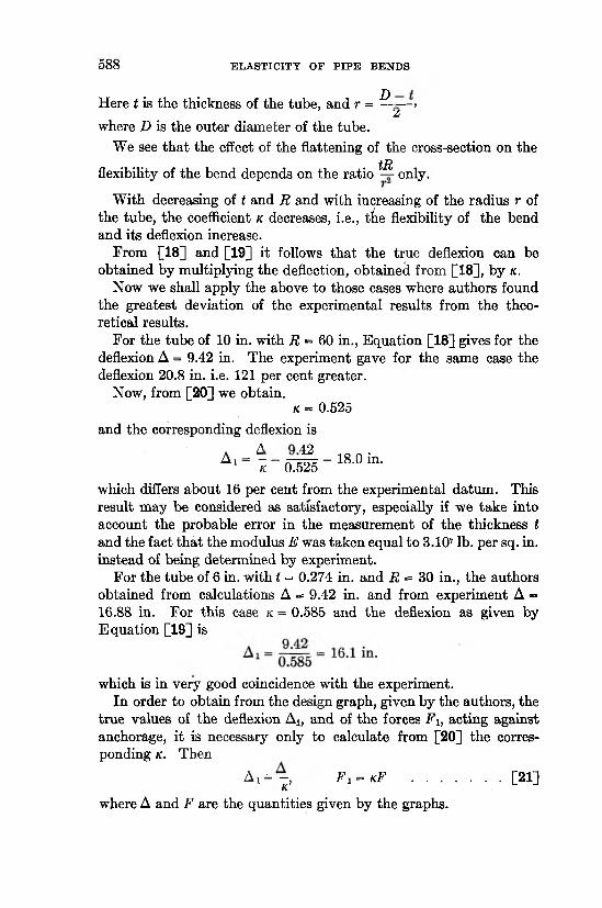
Here t is the thickness of the tube, and r = ^ ->£
where D is the outer diameter of the tube.We see tha t the effect of the flattening of the cross-section on the
tRflexibility of the bend depends on the ratio only.
With decreasing of t and R and with increasing of the radius r of the tube, the coefficient k decreases, i.e., tiie flexibility of the bend and its deflexion increase.
From [18] and [19] it follows that the true deflexion can be obtained by multiplying the deflection, obtained from [18], by k.
Now we shall apply the above to those cases where authors found the greatest deviation of the experimental results from the theoretical results.
For the tube of 10 in. with R = 60 in., Equation [18] gives for the deflexion A = 9.42 in. The experiment gave for the same case the deflexion 20.8 in. i.e. 121 per cent greater.
Now, from [20] we obtain.k = 0.525
and the corresponding deflexion is
A ' - 1 r i n f i - 18-0 t a -which differs about 16 per cent from the experimental datum. This result may be considered as satisfactory, especially if we take into account the probable error in the measurement of the thickness t and the fact that the modulus E was taken equal to 3.107 lb. per sq. in. instead of being determined by experiment.
For the tube of 6 in. with I = 0.274 in. and R = 30 in., the authors obtained from calculations A = 9.42 in. and from experiment A - 16.88 in. For this case k = 0.585 and the deflexion as given by Equation [19] is
which is in very good coincidence with the experiment.In order to obtain from the design graph, given by the authors, the
true values of the deflexion Ai, and of the forces F i, acting against anchorage, it is necessary only to calculate from [20] the corresponding k. Then
A i = - , F x = kF ........................[21]K
where A and F are the quantities given by the graphs.
DISCUSSION 5 8 9
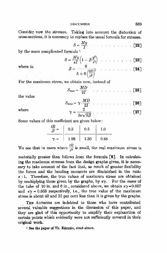
Consider now the stresses. Taking into account the distortion of cross-sections, it is necessary to replace the usual formula for stresses.
by the more complicated formula
tRWe see that in cases where - r is small, the real maximum stress isr2materially greater than follows from the formula [8]. In calculating the maximum stresses from the design graphs given, it is necessary to take account of the fact that, as result of greater flexibility the forces and the bending moments are diminished in the ratio k : 1. Therefore, the true values of maximum stress are obtained by multiplying those given by the graphs, by k j . For the cases of the tube of 10 in. and 6 in., considered above, we obtain «y=0.607 and k j = 0.658 respectively, i.e., the true value of the maximum stress is about 40 and 35 per cent less than it is given by the graphs.
T h e A u t h o r s are indebted to those who have contributed several valuable suggestions in the discussion of this paper, and they are glad of this opportunity to amplify their explanation of certain points which evidently were not sufficiently covered in their original work.
1 See the paper of T h. K&rmdn, cited above.
5 9 0 ELASTICITY OF PIPE BENDS
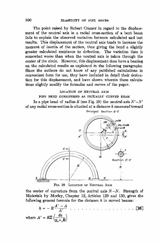
The point raised by Robert Cramer in regard to the displacement of the neutral axis in a radial cross-section of a bent beam fails to explain the observed variation between calculated and test results. This displacement of the neutral axis tends to increase the moment of inertia of the section, thus giving the bend a slightly greater calculated resistance to deflection. The variation then is somewhat worse than when the neutral axis is taken through the center of the circle. However, this displacement does have a bearing on the calculated results as explained in the following paragraphs. Since the authors do not know of any published calculations in convenient form for use, they have included in detail their derivation for this displacement, and have shown wherein these calculations slightly modify the formulas and curves of the paper.
L O C A T IO N O F N E U T R A L A X IS
P I P E B E N D C O N S ID E R E D A S IN IT IA L L Y C U R V E D B E A M
In a pipe bend of radius R (see Fig. 29) the neutral axis N '—N' of any radial cross-section is situated at a distance h measured toward
E n la rg e d S e c + io n C~C
the center of curvature from the central axis N - N . Strength of Materials by Morley, Chapter 12, Articles 129 and 130, gives the following general formula for the distance h in curved beams:
n = - R ^ A ................................................ ■ - - [28]
where A’ = RZ ( - f i , )\y.+ .RJ
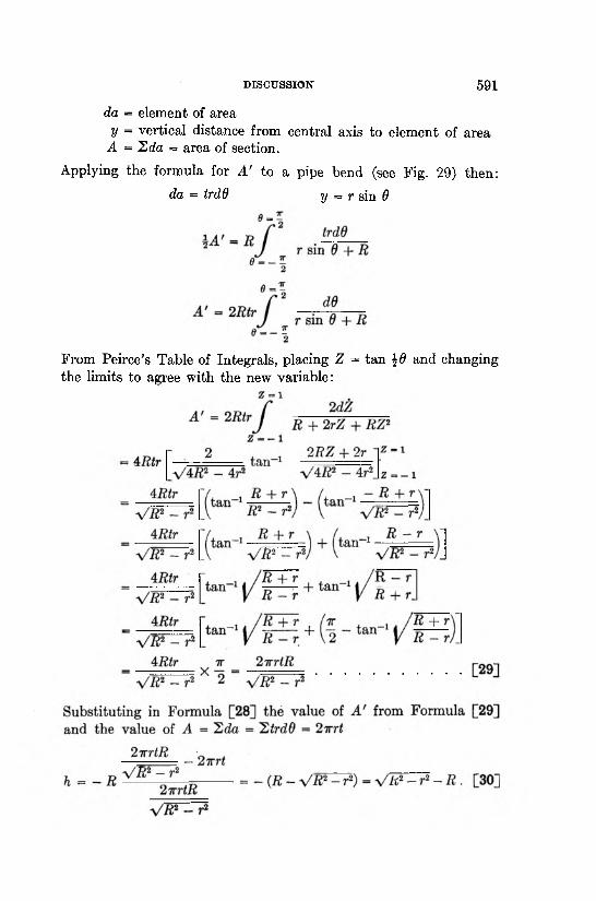
DISCUSSION 5 9 1
da = element of area y = vertical distance from central axis to element of area
A = hda = area of section.
Applying the formula for A ' to a pipe bend (see Fig. 29) then:da = trdd y = r sin 6
From Peirce’s Table of Integrals, placing Z = tan \6 and changing the limits to agree with the new variable:
5 9 2 ELASTICITY OF PIPE BENDS
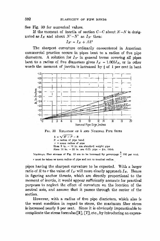
See Fig. 30 for numerical values.If the moment of inertia of section C - C about N - N is desig
nated as I n and about N ' —N ' as I n- then:I n’ = I n + Ah2
The sharpest curvature ordinarily encountered in American commercial practice occurs in pipes bent to a radius of five pipe diameters. A solution for I n ' in general terms covering all pipes bent to a radius of five diameters gives I n = 1.005/jv, or in other words the moment of inertia is increased by J of 1 per cent in bent
F ig . 30 R e l a t i o n o f h a n d N o m in a l P ip e S iz e s
a - V B2 - r2 - RR = radius of pipe bend r — mean radius of pipe
Sizes 2 in. — 12 in. are s tandard weight pipe Sizes 14 in. — 20 in. are O.D. pipe £in. thick
hM aximum fiber stresses of Fig. 12 are to be increased by percentage - 100 per cent.
rt m ust be taken as m ean radius of pipe and not as nominal radius.
pipes having the sharpest curvature to be expected. With a larger ratio of R to r the value of I n ' will more closely approach I n - Hence in figuring anchor thrusts, which are directly proportional to the moment of inertia, it would appear sufficiently accurate for practical purposes to neglect the effect of curvature on the location of the neutral axis, and assume that it passes through the center of the section.
However, with a radius of five pipe diameters, which also is the worst condition in regard to stress, the maximum fiber stress is increased nearly 5 per cent. Since it is obviously impracticable to complicate the stress formulas [5], [7], etc., by introducing an expres
DISCUSSION 5 9 3
sion involving the value of h, this increased stress may be taken into account, a t the discretion of the designer, by adding a percentage to the stress values worked out from the stress formula, or taken from Fig. 12. Fig. 30 furnishes a convenient means of deter
mining the percentage to add, which is approximately ^ X 100 per
cent. I t should be noted that r must be taken as the mean radius of the pipe and not the nominal radius.
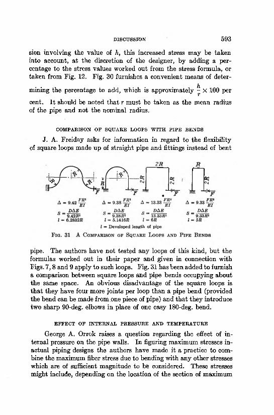
COMPARISON OF SQUARE LOOPS WITH PIPE BENDS
J. A. Freiday asks for information in regard to the flexibility of square loops made up of straight pipe and fittings instead of bent
pipe. The authors have not tested any loops of this kind, but the formulas worked out in their paper and given in connection with Figs. 7 ,8 and 9 apply to such loops. Fig. 31 has been added to furnish a comparison between square loops and pipe bends occupying about the same space. An obvious disadvantage of the square loops is that they have four more joints per loop than a pipe bend (provided the bend can be made from one piece of pipe) and that they introduce two sharp 90-deg. elbows in place of one easy 180-deg. bend.
EFFECT OF INTERNAL PRESSURE AND TEMPERATURE
George A. Orrok raises a question regarding the effect of internal pressure on the pipe walls. In figuring maximum stresses inactual piping designs the authors have made it a practice to combine the maximum fiber stress due to bending with any other stresses which are of sufficient magnitude to be considered. These stresses might include, depending on the location of the section of maximum
5 9 4 ELASTICITY OF PIPE BENDS
stress, bursting stress and longitudinal stress due to internal pressure, shearing stress, and direct compressive stress due to anchor thrust.
The authors believe tha t the temperature a t which the pipe is operated would not immediately affect the stress and thrust conditions, provided the maximum combined stress does not exceed the elastic limit of the material a t the temperature in question. Gradual distortion or growth of the metal, while subject to high temperatures over a long period of time, may eventually produce a change from the original conditions of stress and thrust. Instances of this nature have been observed in the superheated steam lines of The Detroit Edison Company, when pipes which were originally
F ig . 32 S p e c ia l U -B e n d M a d e fr o m Q u a r t e r B e n d s a n d T a n g e n t s
cold-sprung did not return to their original position when unbolted after a period of service. For this reason the authors doubt whether it is safe practice to rely too much on cold springing for relieving expansion forces in high temperature lines.
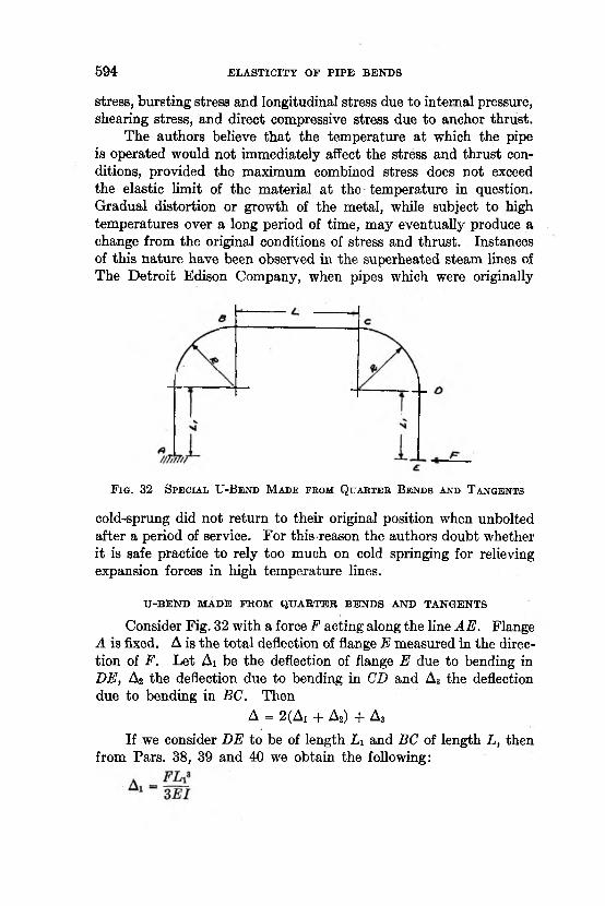
U-BEND MADE FROM QUARTER BENDS AND TANGENTS
Consider Fig. 32 with a force F acting along the line AE. Flange A is fixed. A is the total deflection of flange E measured in the direction of F. Let Ai be the deflection of flange E due to bending in DE, A2 the deflection due to bending in CD and A3 the deflection due to bending in BC. Then
A = 2 (Ai + A2) + A3
If we consider DE to be of length L x and BC of length L, then from Pars. 38, 39 and 40 we obtain the following:
DISCUSSION 5 9 5
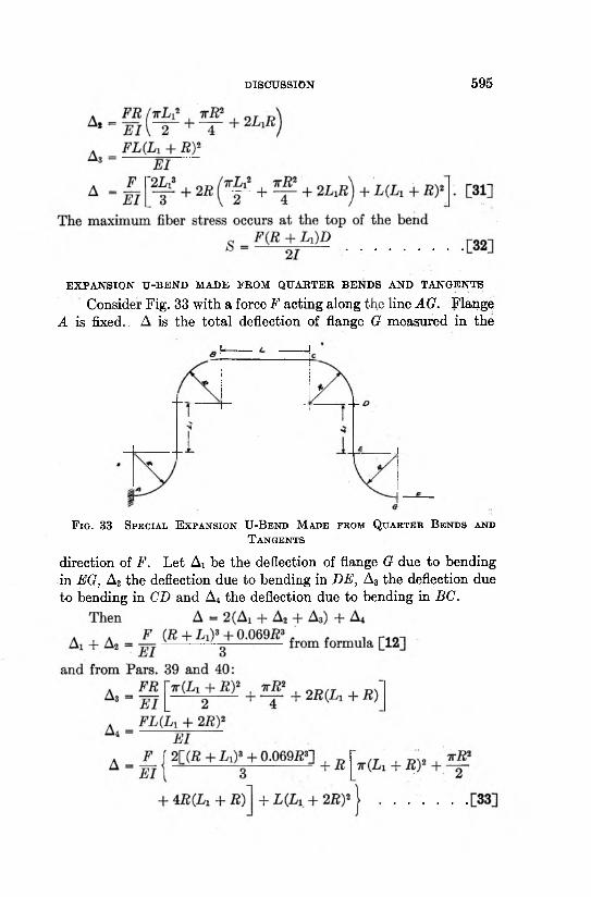
EXPANSION U-BEND MADE PROM QUARTER BENDS AND TANGENTS
Consider Fig. 33 with a force F acting along the line AG. Flange A is fixed.. A is the total deflection of flange G measured in the
F i g . 33 S p e c ia l E x p a n s io n U -B e n d M a d e f r o m Q u a r t e r B e n d s a n d
T a n g e n t s
direction of F. Let Ai be the deflection of flange G due to bending in EG, A2 the deflection due to bending in DE, A3 the deflection due to bending in CD and A4 the deflection due to bending in BC.
5 9 6 ELASTICITY OP PIPE BENDS
The maximum bending stress occurs a t the top of the bend.
5 = ZHQM+Ld ...............................................................................................................[34]
Tangents a t A and G are not shown inasmuch as they lie in the line of action of the force and therefore have no effect on the flexibility of the bend.
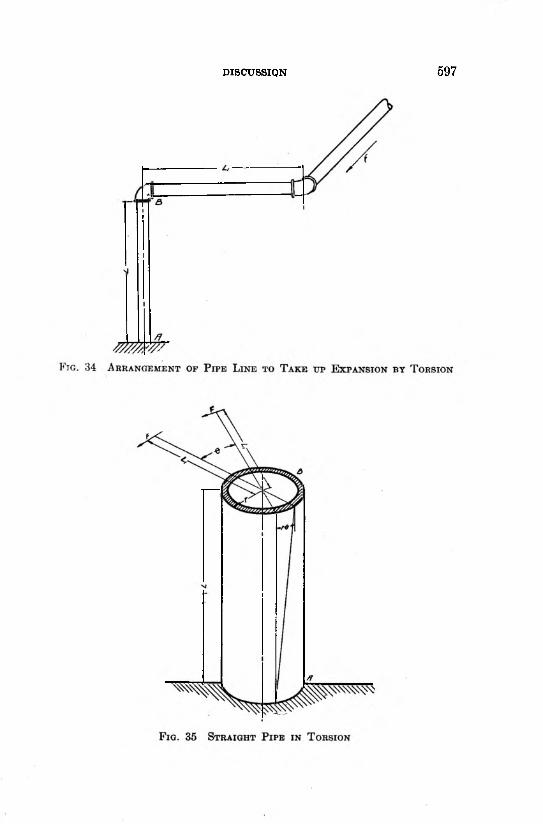
ELASTICITY OP A STRAIGHT PIPE IN TORSION
Consider the pipe shown in Fig. 35. End A is anchored in such a way tha t it is not free to turn, and end B is subjected to a torque T.
The fundamental torsion formula is
T = aLr
whereT = torque, inch poundsq = maximum shearing stress due to torsion, lb. per sq. in. r = outside radius of pipe, inchesJ = polar moment of inertia of circular cross section about
axis of pipe.T = FLi
whereF = force, pounds
andLi = distance in inches of line of action of force F from center
line of pipe under torsion. g _ shearing stress
shearing strainG = modulus of shearing elasticity (11,500,000 lb. per sq. in.
for steel)- T 0 Shearing strain =
Li
6 = angle of twistL = length of pipe under torsion, inches.
DISCUSSION 5 9 7
5 9 8 ELASTICITY OF PIPE BENDS
Let A be the distance through which the force F acts, in other words the expansion of a pipe line which is to be taken up in torsion
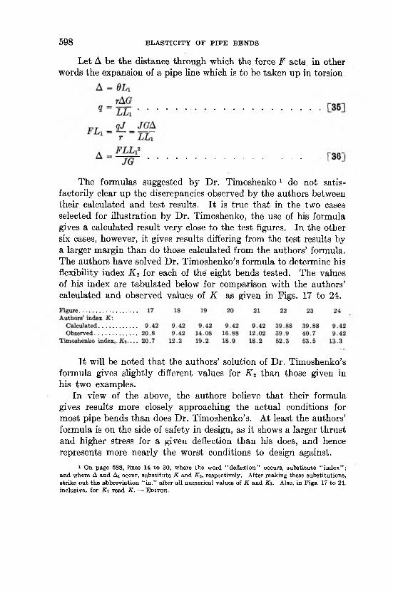
The formulas suggested by Dr. Timoshenko 1 do not satisfactorily clear up the discrepancies observed by the authors between their calculated and test results. It is true that in the two cases selected for illustration by Dr. Timoshenko, the use of his formula gives a calculated result very close to the test figures. In the other six cases, however, it gives results differing from the test results by a larger margin than do those calculated from the authors’ formula. The authors have solved Dr. Timoshenko’s formula to determine his flexibility index K 2 for each of the eight bends tested. The values of his index are tabulated below for comparison with the authors’ calculated and observed values of K as given in Figs. 17 to 24.
It will be noted that the authors’ solution of Dr. Timoshenko’s formula gives slightly different values for K 2 than those given in his two examples.
In view of the above, the authors believe that their formula gives results more closely approaching the actual conditions for most pipe bends than does Dr. Timoshenko’s. At least the authors’ formula is on the side of safety in design, as it shows a larger thrust and higher stress for a given deflection than his does, and hence represents more nearly the worst conditions to design against.
1 On page 588, lines 14 to 30, where the word “ deflexion” occurs, substitu te “ index” ; and where A and Ai occur, substitu te K and K 2 , respectively. After making these substitutions, strike ou t the abbreviation “ in .” a fter all numerical values of K and K i. Also, in Figs. 17 to 24. inclusive, for K i read K . — E d i t o r .