nkl pp positioner 601 series valves - northvale korting
TRANSCRIPT
NORTHVALE KORTING LTD, UXBRIDGE RD, LEICESTER, ENG, LE4 7ST, TEL 0044 (0) 116 2665911, FAX 0044 (0) 116 2610050,
EMAIL [email protected]
1
YT-1200 SERIES PNEUMATIC POSITIONERS
FOR 601 SERIES – 15-65mm
BOSSMATIC PARAGON CONTROL VALVES
Installation, Operating
&
Maintenance Instructions
Index.
Section Page Nos.
A. Mounting Instructions 2
B. Changing Positioner Location 3
Young Tech Instruction Manual 4 - 12
Document Reference: POSYTC1E Issue: 3 Date: 29/04/03 abcde
NORTHVALE KORTING LTD, UXBRIDGE RD, LEICESTER, ENG, LE4 7ST, TEL 0044 (0) 116 2665911, FAX 0044 (0) 116 2610050,
EMAIL [email protected]
2
A. Mounting Instructions A1. Ensure that the actuator and spindle coupling are correctly orientated; the holes in the underside of the
actuator and the holes in the spindle coupling must be on the same side of the valve. For changing the positioner location see below.
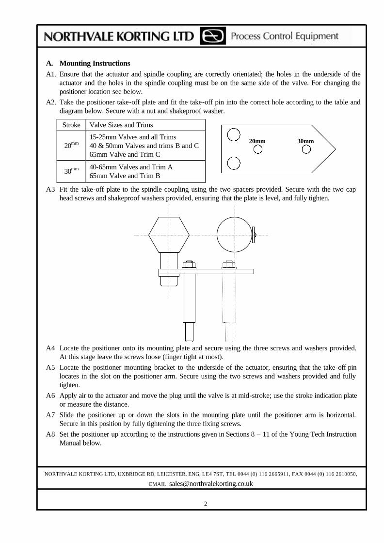
A2. Take the positioner take-off plate and fit the take-off pin into the correct hole according to the table and diagram below. Secure with a nut and shakeproof washer.
Stroke Valve Sizes and Trims
20mm 15-25mm Valves and all Trims 40 & 50mm Valves and trims B and C 65mm Valve and Trim C
30mm 40-65mm Valves and Trim A 65mm Valve and Trim B
A3 Fit the take-off plate to the spindle coupling using the two spacers provided. Secure with the two cap head screws and shakeproof washers provided, ensuring that the plate is level, and fully tighten.
A4 Locate the positioner onto its mounting plate and secure using the three screws and washers provided.
At this stage leave the screws loose (finger tight at most).
A5 Locate the positioner mounting bracket to the underside of the actuator, ensuring that the take-off pin locates in the slot on the positioner arm. Secure using the two screws and washers provided and fully tighten.
A6 Apply air to the actuator and move the plug until the valve is at mid-stroke; use the stroke indication plate or measure the distance.
A7 Slide the positioner up or down the slots in the mounting plate until the positioner arm is horizontal. Secure in this position by fully tightening the three fixing screws.
A8 Set the positioner up according to the instructions given in Sections 8 – 11 of the Young Tech Instruction Manual below.
20mm 30mm
NORTHVALE KORTING LTD, UXBRIDGE RD, LEICESTER, ENG, LE4 7ST, TEL 0044 (0) 116 2665911, FAX 0044 (0) 116 2610050,
EMAIL [email protected]
3
B Changing Positioner Location.
B1 Valves are generally supplied with the positioner mounted on the front of the valve with flow from left to right, but can be moved to the opposite side by following these instructions.
B2 Undo the nuts securing the copper interconnecting pipework between the positioner and actuator and remove this pipework.
B3 Undo the two bolts securing the positioner-mounting bracket to the actuator and remove the positioner/bracket assembly complete.
B4 Undo the air connection (elbow) in the actuator and exchange it with the blanking plug on the opposite side of the actuator. When refitting the air connection and blanking plug use a suitable sealant on the threads.
B5 Undo the two cap head screws on the positioner take-off arm assembly and remove the positioner take-off arm assembly ensuring the spacers are retained.
B6 Re-locate the positioner take-off arm assembly onto the opposite side of the spindle coupling and refasten ensuring that the spacers are fitted and the take-off is level. See section A for further details.
B7 Re-locate the positioner/bracket assembly to the opposite side of the valve and secure to the underside of the actuator using two bolts, ensuring that the take-off arm is correctly located into the pivot-arm on the back of the positioner.
B8 Reconnect the copper interconnecting pipework between the positioner and actuator adjusting the angle of the pneumatic connection (elbow) on the actuator as necessary.
B9 Check the positioner for correct operation as detailed below.
4
Pneumatic-pneumatic
Positioners Instruction Manual
YOUNG TECH CO., LTD.
#303 Duckhung B/D., 147-7 Dongkyo-dong, Mapo-ku, Seoul, Korea PHONE: 82-2-3143-4544 FAX: 82-2-3143-4546
5
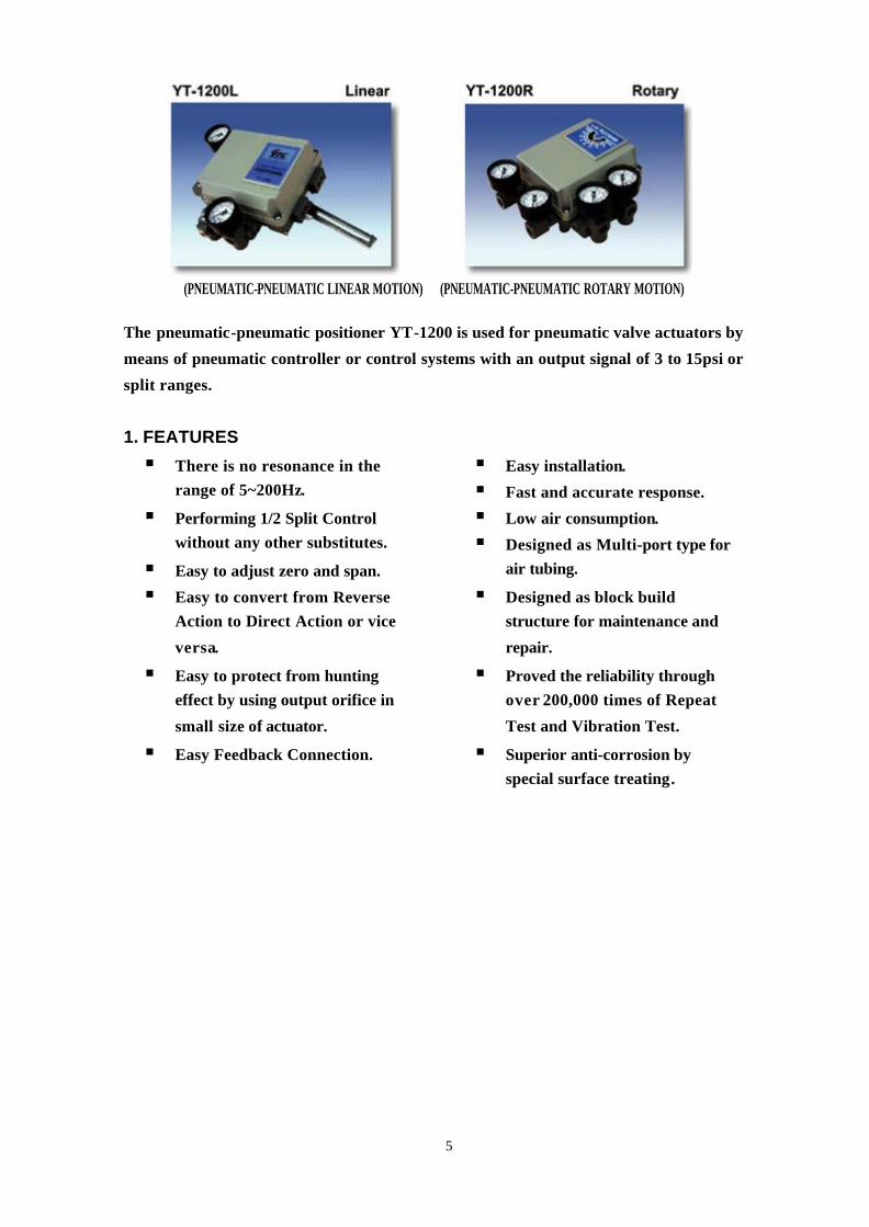
(PNEUMATIC-PNEUMATIC LINEAR MOTION) (PNEUMATIC-PNEUMATIC ROTARY MOTION)
The pneumatic-pneumatic positioner YT-1200 is used for pneumatic valve actuators by
means of pneumatic controller or control systems with an output signal of 3 to 15psi or
split ranges.
1. FEATURES
§ There is no resonance in the
range of 5~200Hz.
§ Performing 1/2 Split Control
without any other substitutes.
§ Easy to adjust zero and span.
§ Easy to convert from Reverse
Action to Direct Action or vice
versa.
§ Easy to protect from hunting
effect by using output orifice in
small size of actuator.
§ Easy Feedback Connection.
§ Easy installation.
§ Fast and accurate response.
§ Low air consumption.
§ Designed as Multi-port type for
air tubing.
§ Designed as block build
structure for maintenance and
repair.
§ Proved the reliability through
over 200,000 times of Repeat
Test and Vibration Test.
§ Superior anti-corrosion by
special surface treating.
- 6 -
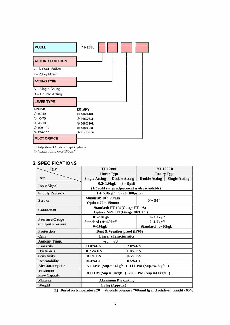
MODEL
YT-1200
ACTUATOR MOTION
L – Linear Motion
R – Rotary Motion
ACTING TYPE
S – Single Acting
D – Double Acting
LEVER TYPE
LINEAR � 10-40 � 40-70 � 70-100 � 100-130 � 130-150
ROTARY � M6X40L � M6X63L � M8X40L � M8X63L � NAMUR
PILOT ORIFICE
� Adjustment Orifice Type (option) � Actuator Volume over 180cm3
3. SPECIFICATIONS
YT-1200L YT-1200R Linear Type Rotary Type
Type Item Single Acting Double Acting Double Acting Single Acting
Input Signal 0.2~1.0kgf/� (3 ~ 5psi) (1/2 split range adjustment is also available)
Supply Pressure 1.4~7.0kgf/�G (20~100psiG)
Stroke Standard: 10 ~ 70mm Option: 70 ~ 150mm
0°~ 90°
Connection Standard: PT 1/4 (Gauge PT 1/8) Option: NPT 1/4 (Gauge NPT 1/8)
Pressure Gauge (Output Pressure)
0 ~2.0kgf/� Standard : 0~4.0kgf/� 0~10kgf/�
0~2.0kgf/� 0~4.0kgf/� Standard : 0~10kgf/�
Protection Dust & Weather proof (IP66) Cam Linear characteristics Ambient Temp. -20�~70� Linearity ±1.0%F.S ±2.0%F.S Hysteresis 0.75%F.S 1.0%F.S Sensitivity 0.1%F.S 0.5%F.S Repeatability ±0.3%F.S ±0.5%F.S Air Consumption 5.0 LPM (Sup.=1.4kgf/�) 11 LPM (Sup.=4.0kgf/�) Maximum Flow Capacity
80 LPM (Sup.=1.4kgf/�) 200 LPM (Sup.=4.0kgf/�)
Material Aluminum Die casting Weight 1.8 kg (Approx.)
(1) Based on temperature 20�, absolute pressure 760mmHg and relative humidity 65%.
- 7 -
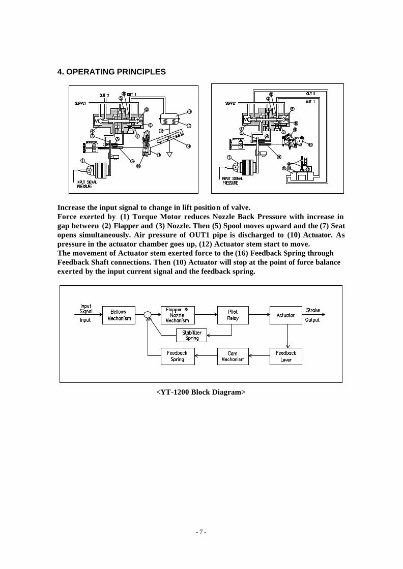
4. OPERATING PRINCIPLES <YT-1200L> <YT-1200R> Increase the input signal to change in lift position of valve. Force exerted by (1) Torque Motor reduces Nozzle Back Pressure with increase in gap between (2) Flapper and (3) Nozzle. Then (5) Spool moves upward and the (7) Seat opens simultaneously. Air pressure of OUT1 pipe is discharged to (10) Actuator. As pressure in the actuator chamber goes up, (12) Actuator stem start to move. The movement of Actuator stem exerted force to the (16) Feedback Spring through Feedback Shaft connections. Then (10) Actuator will stop at the point of force balance exerted by the input current signal and the feedback spring.
<YT-1200 Block Diagram>
- 8 -
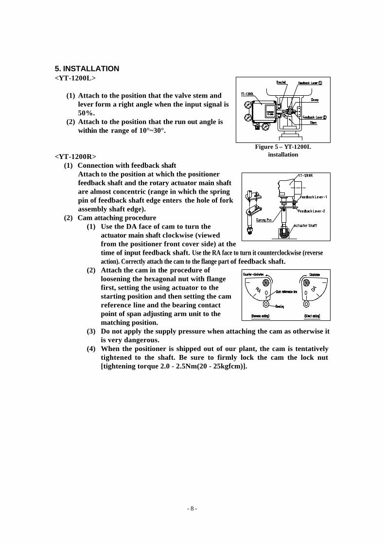
5. INSTALLATION <YT-1200L>
(1) Attach to the position that the valve stem and lever form a right angle when the input signal is 50%.
(2) Attach to the position that the run out angle is within the range of 10°~30°.
<YT-1200R>
(1) Connection with feedback shaft Attach to the position at which the positioner feedback shaft and the rotary actuator main shaft are almost concentric (range in which the spring pin of feedback shaft edge enters the hole of fork assembly shaft edge).
(2) Cam attaching procedure (1) Use the DA face of cam to turn the
actuator main shaft clockwise (viewed from the positioner front cover side) at the time of input feedback shaft. Use the RA face to turn it counterclockwise (reverse action). Correctly attach the cam to the flange part of feedback shaft.
(2) Attach the cam in the procedure of loosening the hexagonal nut with flange first, setting the using actuator to the starting position and then setting the cam reference line and the bearing contact point of span adjusting arm unit to the matching position.
(3) Do not apply the supply pressure when attaching the cam as otherwise it is very dangerous.
(4) When the positioner is shipped out of our plant, the cam is tentatively tightened to the shaft. Be sure to firmly lock the cam the lock nut [tightening torque 2.0 - 2.5Nm(20 - 25kgfcm)].
Figure 5 – YT-1200L installation
- 9 -
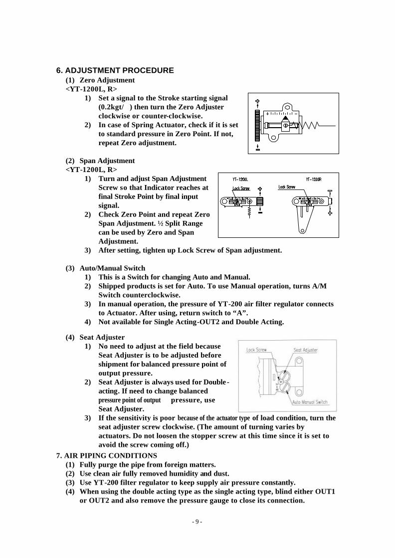
6. ADJUSTMENT PROCEDURE (1) Zero Adjustment <YT-1200L, R>
1) Set a signal to the Stroke starting signal (0.2kgt/�) then turn the Zero Adjuster clockwise or counter-clockwise.
2) In case of Spring Actuator, check if it is set to standard pressure in Zero Point. If not, repeat Zero adjustment.
(2) Span Adjustment <YT-1200L, R>
1) Turn and adjust Span Adjustment Screw so that Indicator reaches at final Stroke Point by final input signal.
2) Check Zero Point and repeat Zero Span Adjustment. ½ Split Range can be used by Zero and Span Adjustment.
3) After setting, tighten up Lock Screw of Span adjustment.
(3) Auto/Manual Switch 1) This is a Switch for changing Auto and Manual. 2) Shipped products is set for Auto. To use Manual operation, turns A/M
Switch counterclockwise. 3) In manual operation, the pressure of YT-200 air filter regulator connects
to Actuator. After using, return switch to “A”. 4) Not available for Single Acting-OUT2 and Double Acting.
(4) Seat Adjuster 1) No need to adjust at the field because
Seat Adjuster is to be adjusted before shipment for balanced pressure point of output pressure.
2) Seat Adjuster is always used for Double -acting. If need to change balanced pressure point of output pressure, use Seat Adjuster.
3) If the sensitivity is poor because of the actuator type of load condition, turn the seat adjuster screw clockwise. (The amount of turning varies by actuators. Do not loosen the stopper screw at this time since it is set to avoid the screw coming off.)
7. AIR PIPING CONDITIONS (1) Fully purge the pipe from foreign matters. (2) Use clean air fully removed humidity and dust. (3) Use YT-200 filter regulator to keep supply air pressure constantly. (4) When using the double acting type as the single acting type, blind either OUT1
or OUT2 and also remove the pressure gauge to close its connection.
- 10 -
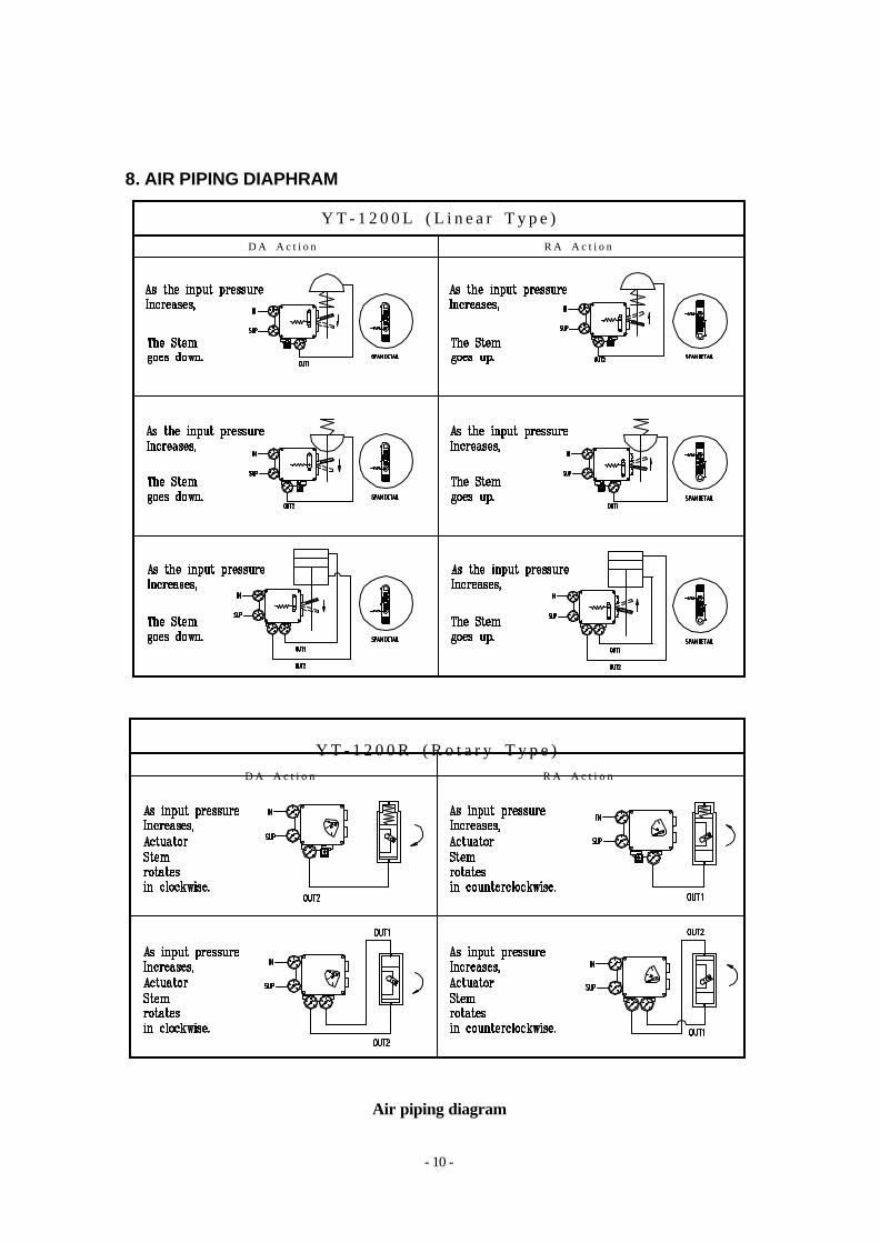
8. AIR PIPING DIAPHRAM
Air piping diagram
D A A c t i o n
Y T - 1 2 0 0 R ( R o t a r y T y p e )
R A A c t i o n
Y T - 1 2 0 0 L ( L i n e a r T y p e )
D A A c t i o n R A A c t i o n
- 11 -
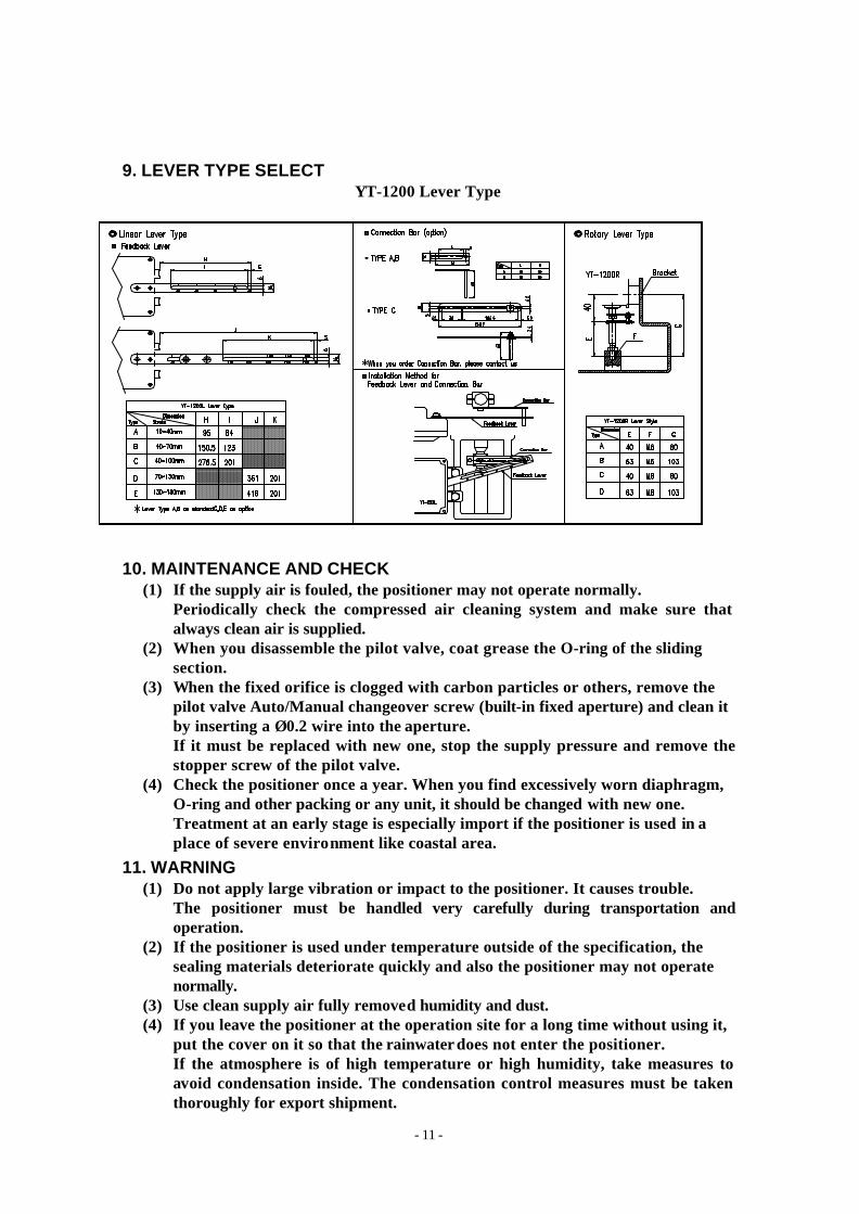
9. LEVER TYPE SELECT YT-1200 Lever Type
10. MAINTENANCE AND CHECK (1) If the supply air is fouled, the positioner may not operate normally.
Periodically check the compressed air cleaning system and make sure that always clean air is supplied.
(2) When you disassemble the pilot valve, coat grease the O-ring of the sliding section.
(3) When the fixed orifice is clogged with carbon particles or others, remove the pilot valve Auto/Manual changeover screw (built-in fixed aperture) and clean it by inserting a Ø0.2 wire into the aperture. If it must be replaced with new one, stop the supply pressure and remove the stopper screw of the pilot valve.
(4) Check the positioner once a year. When you find excessively worn diaphragm, O-ring and other packing or any unit, it should be changed with new one. Treatment at an early stage is especially import if the positioner is used in a place of severe environment like coastal area.
11. WARNING (1) Do not apply large vibration or impact to the positioner. It causes trouble.
The positioner must be handled very carefully during transportation and operation.
(2) If the positioner is used under temperature outside of the specification, the sealing materials deteriorate quickly and also the positioner may not operate normally.
(3) Use clean supply air fully removed humidity and dust. (4) If you leave the positioner at the operation site for a long time without using it,
put the cover on it so that the rainwater does not enter the positioner. If the atmosphere is of high temperature or high humidity, take measures to avoid condensation inside. The condensation control measures must be taken thoroughly for export shipment.
- 12 -
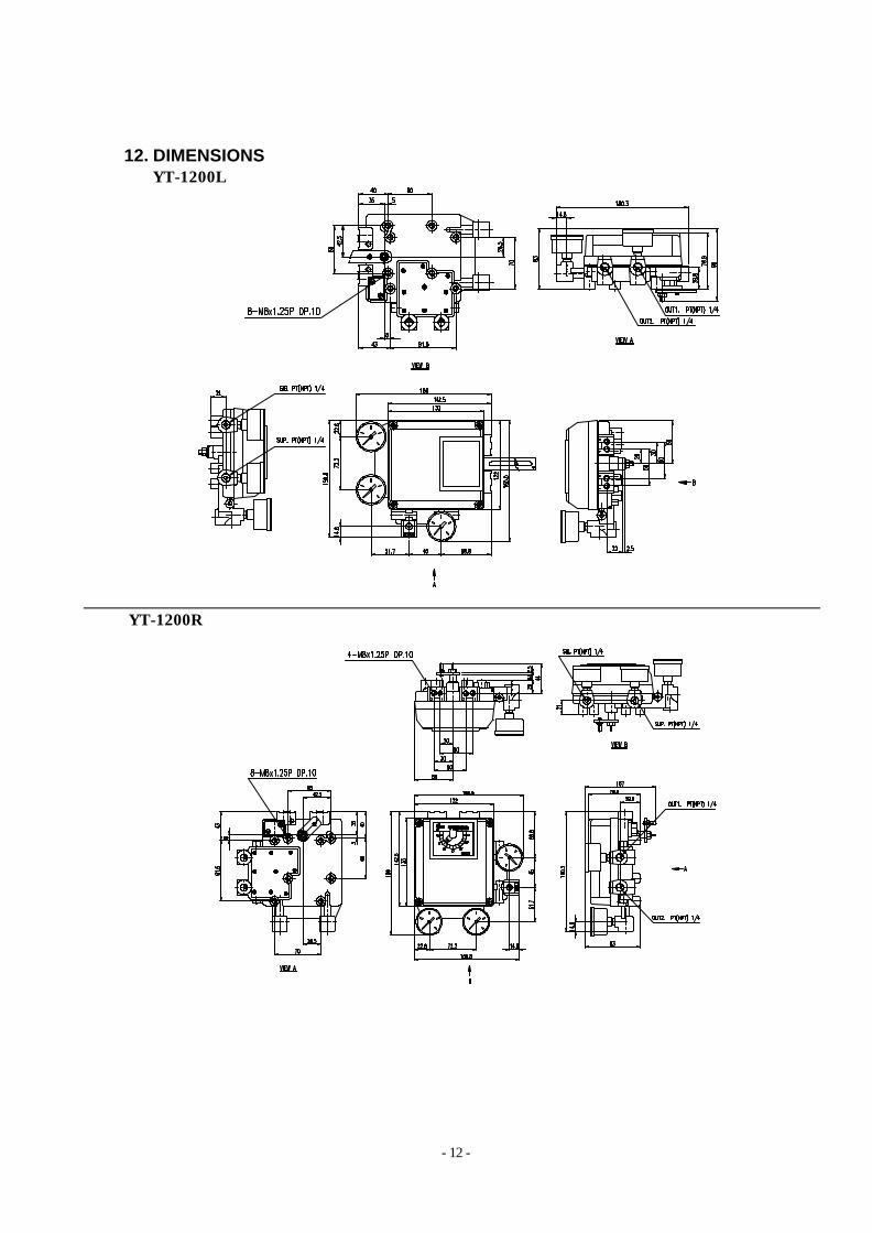
12. DIMENSIONS � YT-1200L
� YT-1200R