nitrification and treatment plants
TRANSCRIPT


Wastewater Treatment Plant
A WWTP is the place where wastewater is treated to
remove pollutants before it enters a water body or
reused.
It includes physical , chemical & biological processes
to remove physical , chemical and biological
contaminations.


Forms Of Nitrogen In Wastewater
• Ammonia – NH3
• Nitrite – NO2-
• Nitrate – NO3-
• Organic nitrogen

• Total Kjeldal Nitogen-TKN
Sum of organic nitrogen + ammonia
• Total Inorganic Nitrogen-TIN
Sum of Ammmonia + Nitrite + Nitrate

Why is it necessary to treat the forms of
nitrogen?
• Improve receiving stream quality
• Increase chlorination efficiency
• Minimize pH changes in plant
• Increase suitability for reuse

• Prevent ammonia toxicity
• Protect groundwater from nitrate contamination
• To control the growth of algae
• To prevent the DO depletion
• Odor problems

• To prevent imbalance of natural ecological systems and
increase of eutrophication
• increase risks to human health, such as NO3-N concentration
in the groundwater for potable use.


• Nitrification is the biological oxidation of ammonia or
ammonium to nitrite followed by the oxidation of the nitrite to
nitrate

Nitrification
NH3-NAmmonia N
NO2-NNitrite N
NO2-NNitrite N
NO3-NNitrate N
Nitrosomonas
Nitrobacter
Nitrification of Ammonia Occurs in
Two Steps

Heterotrophic Bacteria Break Down Organics
Generate NH3, CO2, and H2O
Autotrophic Bacteria Utilize Inorganic Compounds
(and CO2 as a Carbon Source)
Assimilation Some Nitrogen Will Be
Removed By The Biomass

Nitrogen cycle
Nitrogen is present in the environment in a wide variety of
chemical forms including
• ammonium (NH4+)
• nitrite (NO2-)
• nitrate(NO3-)
• nitric oxide (NO) or
• nitrous oxide (N2O)
• inorganic nitrogen gas (N2)
• organic nitrogen

• Organic nitrogen may be in the form of a living organism, humus or in the intermediate products of organic matter decomposition.
• The processes of the nitrogen cycle transform nitrogen from one form to another.
• Many of those processes are carried out by microbes, either in their effort to harvest energy or to accumulate nitrogen in a form needed for their growth.

The processes of Nitrogen cycle
1. Nitrogen Fixation
2. Assimilation
3. Ammonification
4. Nitrification
5. Denitrification
N-
CYCLE
Nitrogen Fixation
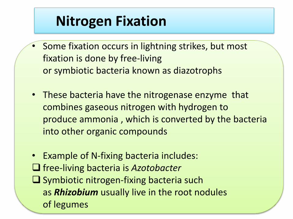
• Some fixation occurs in lightning strikes, but most fixation is done by free-living or symbiotic bacteria known as diazotrophs
• These bacteria have the nitrogenase enzyme that combines gaseous nitrogen with hydrogen to produce ammonia , which is converted by the bacteria into other organic compounds
• Example of N-fixing bacteria includes: free-living bacteria is Azotobacter Symbiotic nitrogen-fixing bacteria such
as Rhizobium usually live in the root nodules of legumes

Assimilation
• Plants take nitrogen from the soil by absorptionthrough their roots in the form ofeither nitrate ions or nitrite ions
• Plants cannot assimilate ammonium ions
• nitrate is absorbed, & reduced to nitrite ions andthen ammonium ions for incorporation into aminoacids, nucleic acids, and chlorophyll
• Animals, fungi, and other heterotrophic organismsobtain nitrogen by ingestion of aminoacids,nucleotides and other small organic molecules

Nitrification
• Nitrification is a microbial process by which reduced nitrogen compounds (primarily ammonia) are sequentially oxidized to nitrite and nitrate
• The conversion of ammonia to nitrate is performed primarily by soil-living bacteria and other nitrifying bacteria
• The nitrification process is primarily accomplished by two groups of autotrophic nitrifying bacteria

In the first step of nitrification,ammonia-oxidizing bacteria oxidizeammonia to nitrite according toequation
NH3 + O2 → NO2 - + 3H+ + 2e-
Nitrosomonas is the most frequentlyidentified genus associated with thisstep, although other genera,including Nitrosococcus, andNitrosospira

In the second step of the process, nitrite-oxidizingbacteria oxidize nitrite to nitrate
NO2 - + H2O → NO3 - + 2H+ +2e-
Nitrobacter is the most frequently identified genusassociated with this second step, although other genera,including Nitrospina, Nitrococcus, and Nitrospira can alsoautotrophically oxidize nitrite
Denitrification
Denitrification is the reduction of nitrates back into the largely inert nitrogen gas (N2), completing the nitrogen cycle. This process
is performed in anaerobic conditions

Total Kjeldahl
Nitrogen
(TKN)
NITROGEN CYCLE
PHYSICO-CHEMICAL NITROGEN REMOVAL
Physico-chemical methods of nitrogen removalhave not been widely applied in waste watertreatment because
They are generally more expensive to operatethan biological treatment;
they produce a poorer effluent quality thanbiological treatment

Air stripping of Ammonia
As the pH increases, a greater proportion ofammonia converts fromNH4to NH3
NH3+H20 NH4 + OH

Ion exchange
Zeolites have been found effective in waste water treatment asmolecular filters which can distinguish molecules
at the ionic level.For example, the natural zeolite
clinoptilolite is selective for the ammonium ion inpreference to other ions present in solution. A
filtered waste water can be passed through a bed of zeolite to effect a 90- 97% ammonium removal

Breakpoint chlorination
By adding chlorine to a
wastewater, a stepwise
reaction takes place which
results in the
conversion of ammonium
to nitrogen gas


N
Secondary “Treatment”(Biological)
WASTEWATER “TREATMENT”Of
Nitrogen

APPROACHESTO SECONDARY TREATMENT
Fixed Film Systems
Suspended Film Systems
Lagoon Systems
organic matter + O2 CO2 + NH3 + H2O
NH3 NO3- aquatic nutrient
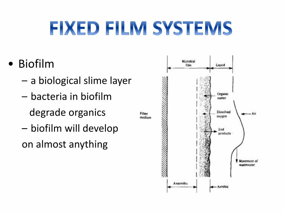
• Biofilm
– a biological slime layer
– bacteria in biofilm
degrade organics
– biofilm will develop
on almost anything

Stir & suspend microorganisms in wastewater.
They absorb organic matter &nutrients fromwaste water.
After hours, they settle as sludge……..Ex…..activated sludge system..etc

Consist of in-ground earthen basins in which the waste is detained for a specifiedtime and then discharged.
They take advantage of natural aeration and microorganisms in the wastewater toremove sewage.
Can be achieved in any• Aerobic-biological process at low organic loadings• Suitable environmental conditionsNitrifying bacteria are slower growing than the heterotrophicbacteriaKey requirement for nitrification to occur, therefore, is that theprocess should be so controlled that the net rate of accumulationof biomass is less than the growth rate of the nitrifying bacteria

1.• Trickling Filters
2.• Rotating Biological Contractor
3.• Fixed Bed Reactor
4.• Conventional Activated Sludge Processes at Low Loadings
5.
• Two-stage Activated Sludge Systems with Separate CarbonaceousOxidation and Nitrification Systems

Wastewater treatment system that• Biodegrades organic matter• Used to achieve nitrificationConsists of• a fixed bed of rocks, lava, coke, polyurethane foam, ceramic, or plastic
mediaAerobic conditions are maintained by splashing, diffusion, and either byforced air flowing through the bed or natural convection of air if the filtermedium is porous.

• Not a true filtering or sieving process• Material only provides surface on which bacteria to grow• Can use plastic media– lighter - can get deeper beds (up to 12 m)– reduced space requirement– larger surface area for growth– better air flow– less prone to plugging by accumulating slime


• Tank is filled with solid media– Rocks– Plastic
• Bacteria grow on surface of media• Wastewater is trickled over media, at top of tank• As water trickles through media, bacteria degrade BOD• Bacteria eventually die, fall off of media surface• Filter is open to atmosphere, air flows naturally through media• Treated water leaves bottom of tank, flows into secondary clarifier• Bacterial cells settle, removed from clarifier as sludge• Some water is recycled to the filter, to maintain moist conditions


Efficient nitrification (ammonium oxidation)
Small land area required

Requires expert design and constructionRequires operation and maintenance by skilled personnelRequires a constant source of electricity and constant
wastewater flowFlies and odours are often problematicRisk of clogging, depending on pre- and primary treatmentNot all parts and materials may be locally available

o Temperature o Dissolved oxygen o pHo Presence of inhibitorso Filter deptho Media type o Loading rateo Wastewater BOD

• A rotating biological contactor or RBC is a biological treatmentprocess used in the treatment of wastewater following primarytreatment.
• The RBC process involves allowing the wastewater to come incontact with a biological medium in order to remove pollutants inthe wastewater before discharge of the treated wastewater tothe environment.
• A rotating biological contactor is a type of secondary treatmentprocess.

• The first RBC was installed in West Germany in 1960,later it was introduced in the United States andCanada.
• In the United States, rotating biological contactorsare used for industries producing wastewaters highin Biochemical Oxygen Demand (BOD)(e.g.,petroleum industry and dairy industry).

• Microorganisms grow on the surface of the discs where biological degradation of the wastewater pollutants takes place.
• It consists of a series of closely spaced, parallel discs mountedon a rotating shaft which is supported just above the surface ofthe waste water.
• Aeration is provided by the rotating action, which exposes themedia to the air after contacting them with the wastewater,facilitating the degradation of the pollutants being removed.
• Biofilms, which are biological growths that become attached tothe discs, assimilate the organic materials in the wastewater.

OPERATION• The rotating packs of disks (known as the
media) are contained in a tank or trough androtate at between 2 and 5 revolutions perminute.
• Commonly used plastics for the media are polythene, PVC and expanded polystyrene.
• The shaft is aligned with the flow ofwastewater so that the discs rotate at rightangles to the flow with several packs usuallycombined to make up a treatment train.
• About 40% of the disc area is immersed in thewastewater.


• Biological growth is attached to the surface of the disc and forms aslime layer. The discs contact the wastewater with the atmospheric airfor oxidation as it rotates.
• The discs consist of plastic sheets ranging from 2 to 4 m in diameter and are up to 10 mm thick. Several modules may be arranged in parallel and/or in series to meet the flow and treatment requirements.
• Approximately 95% of the surface area is thus alternately submerged in waste water and then exposed to the atmosphere above the liquid.


• Carbonaceous substrate is removed in the initial stage ofRBC.
• Carbon conversion may be completed in the first stage of aseries of modules, with nitrification being completed afterthe 5th stage, when the BOD5 was low enough.
• Most design of RBC systems will include a minimum of 4 or5 modules in series to obtain nitrification of waste water.
• The rotation of the disks contacts the biomass in thewastewater ,then with the atmosphere for adsorption ofoxygen.
• Biomass uses the oxygen & organic matter for food thusreducing the BOD in the wastewater.

• Ammonia oxidizers could not effectively compete with thefaster-growing heterotrophs that oxidize organic matter.
• Nitrification occurs only when the BOD was reduced toapproximately 14 mg/L, and increases with rotation speed.
• RBC performance was negatively affected by low dissolvedoxygen in the first stages and by low pH in the later stageswhere nitrification occurred.

A schematic cross-section of the contact face of the bed media in a rotating biological contactor (RBC)
• The degree of wastewater treatment is related to the amountof media surface area and the quality and volume of theinflowing wastewater.

Fixed Bed Reactor
A type of continuous reactor in which the reactants arefeed continuously into the reactor at one point, allowthe reaction to take place and withdraw the products atanother point.

Working Principle
• In these reactors, the reaction takes place inthe form of a heterogeneously catalyzed gasreaction on the surface of catalysts/in biofilmsthat are arranged as a so-called fixed bed inthe reactor.

Fixed bed reactor:Raschig rings are piecesof tube used in largenumbers as a packedbed to support biofilms.

• Ammonia and nitrite oxidizer communities are fixed on the bed material (Raschig rings, Pall rings, Hiflow, Flocor) to form biofilms.
• AOB occupied the outside layers of the biofilm, whereas NOB which found in the deep layers of the biofilm
• A high cell concentration is possible with immobilized biomass, because of large solids retention time.

Schematic of cross-sectional view of bioflim presenting spatial distribution of ammonia oxidizing bacteria (AOB) and nitrite oxidizing bacteraia (NOB) species and diffusion of substrate across the biofilm.

Schematic diagram of experimental setup of up-flow fixed-bed reactor

Basics Setup for FBRs
• The wastewater reaches the first tank (chamber) of thetreatment plant via the inlet sewer.
• The second tank absorbs hydraulic fluctuations
• A filling pump (pneumatic or electrical) feeds thebiological stage evenly (over a period of 24 hours).This ensures that in the event of subsequent loadfluctuations the most favourable operating mode canalways be set

• Gravity pipes are used to fill standard treatment plants, and there is no buffer pump.
• A biological layer (micro-organic colonisation) forms on the fixed-bed material after the start-up period.
• The aeration system installed underneath the fixed-bed material supplies the organisms with sufficient air

Ammonia Oxidizers:
Ammonia N Nitrite N
• Four major groups of ammonia oxidizer microorganismsare known:-
• Ammonia-oxidizing Archaea (AOA): e.g Nitrosopumilusmaritimus, Nitrososhaera gargensis, Nitrosocaldusyellowstonii
• Ammonia-oxidizing bacteria (AOB): e.g N. eutropha, N.oligotropha, Nitrosospira multiformis
• Heterotrophic nitrifiers: e.g Paracoccus pantotrophus
• Anammox bacteria: e.g microbes of the orderPlanctomycetales

Nitrite oxidizers:
Nitrite N Nitrate N
• Nitrite-oxidizing bacteria (NOB): e.gNitrobacter, Nitrococcus, Nirtospira

Conditions for Optimal Nitrification
• Nitrification significantly consumes oxygen.
oxidation of 1 mg liter-1 NH4+ to nitrate -------------- 3.6 mg liter-1 oxygen is required
• Most strains of nitrifying bacteria are pH sensitive.
optimal growth ------------ pH 7 to 8
• Reduction of carbonaceous BOD (cBOD) is a preliminary requirement:
Best results ------------- when cBOD < 30 mg/L.
• Temperature
Min. 59 Degrees F. (15oC) ----------- 90 % Nitrification

• The hydraulic retention time (HRT) is the average retention time of wastewater in the reactor.
“the ratio of liquid volume (V liquid) in the reactor and the flow rate (Q)”
Depend on: Liquid Volume
Flow Rate

Drawbacks of FBRs
Traditional fixed-bed reactors can be easily blocked through:
• excessive growth of microorganisms
• crystalization of dissolved matter
• solids which are fed in.

CONVENTIONAL ACTIVATED SLUDGE PROCESS

ACTIVATED SLUDGE
sludge particles produced by the growth ofmicroorganisms in aerated tanks as a part of theactivated sludge process to treat wastewater

Activated Sludge Process
The most common suspended growth process usedfor municipal wastewater treatment is theactivated sludge process

In activated sludge process wastewater containing organic matter isaerated in an aeration basin in which micro-organisms metabolize thesuspended and soluble organic matter.
Part of organic matter is synthesized into new cells and part is oxidized to CO2 and water to derive energy.
In activated sludge systems the new cells formed in the reaction areremoved from the liquid stream in the form of a flocculent sludge insettling tanks.
A part of this settled biomass, described as activated sludge isreturned to the aeration tank and the remaining forms waste orexcess sludge are discharged off as effluent.

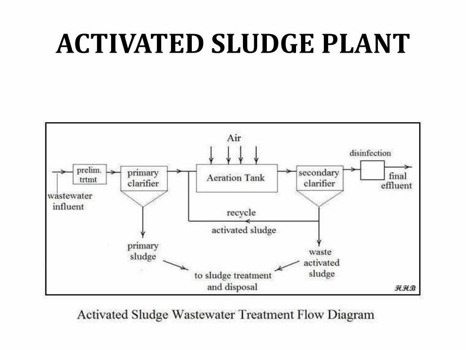
ACTIVATED SLUDGE PLANT
Activated sludge plant involves:
• wastewater aeration in the presence of a microbial suspension
• solid-liquid separation following aeration
• discharge of clarified effluent
• wasting of excess biomass
• return of remaining biomass to the aeration tank
ACTIVATED SLUDGE PLANT
Weismann (1994) studied the nitrification in a conventionalactivated sludge system and found that it was relatively low forcarbon removal and nitrification of sewage because carbon removaland nitrification occurred in the same reactor with an activatedsludge system.
This resulted in a population mixture of mainly heterotrophs andfew autotrophs. In this kind of treatment system, it was not possibleto enrich the autotrophic bacteria because the slower growingautotrophs were removed with the surplus sludge. It was necessaryto separate the autotrophic from the heterotrophic biomass in orderto increase the specific nitrification rate.

Suwa, et al. (1989), conducted a research on simultaneousorganic carbon removal-nitrification by an activated sludgeprocess with cross-flow filtration.
Because of the recycle of sludge with cross-flow filtration, thisprocess made the sludge retention time very long; simultaneouscarbon removal-nitrification was achieved quite well under theloading rate of about 0.10 g BOD/g VSS/d. The efficiency ofdissolved organic carbon removal was more than 95%, andnitrification was sufficient

Two Stage Activated Sludge System With Separate Carbonaceous
Oxidation and Nitrification System
Activated sludge
• Activated sludge is a process for treating sewage and industrial wastewaters using air and a biological floc composed of bacteria and protozoa.

Purpose
• In a sewage (or industrial wastewater)treatment plant, the activated sludge processis a biological process that can be used for oneor several of the following purposes:
• oxidizing carbonaceous biological matter• oxidizing nitrogenous matter
mainly ammonium and nitrogen in biological matter.
• removing phosphates

Purpose
• driving off entrained gases suchas carbondioxide, ammonia, nitrogen, etc.
• generating a biological floc that is easy tosettle.
• generating a liquor that is low in dissolved orsuspended material.

The process
• The process involves air or oxygen beingintroduced into a mixture of screened
• and primary treated sewage or industrialwastewater (wastewater) combined withorganisms to develop a biological floc whichreduces the organic content of the sewage.
• This material, which in healthy sludge is a brownfloc, is largely composed of saprotrophic bacteriabut also has an important protozoan flora mainlycomposed of amoebae and a range of otherspecies.

The process
• In poorly managed activated sludge, a range of filamentous bacteria can develop which produces a sludge that is difficult to settle and can result in the sludge blanket decanting over the weirs in the settlement tank to severely contaminate the final effluent quality.
• This material is often described as sewage fungus but true fungal communities are relatively uncommon.

The process
• The combination of wastewater and biological mass is commonly known as mixed liquor.
• In all activated sludge plants, once the wastewater has received sufficient treatment, excess mixed liquor is discharged into settling tanks and the treated supernatant is run off to undergo further treatment before discharge.

The process
• Part of the settled material, the sludge, is returned to the head of the aeration system to re-seed the new wastewater entering the tank.
• This fraction of the floc is called return activated sludge (R.A.S.). Excess sludge is called surplus activated sludge (S.A.S.) or waste activated sludge (W.A.S).

• W.A.S is removed from the treatment processto keep the ratio of biomass to food suppliedin the wastewater in balance, and is furthertreated by digestion, either under anaerobicor aerobic conditions prior to disposal.

Activated sludge control
• The general method to do this is to monitor
• sludge blanket level
• SVI (Sludge Volume Index)
• MCRT (Mean Cell Residence Time)
• F/M (Food to Microorganism), as well as the of the activated sludge and the major
• Nutrients
• DO (Dissolved oxygen),
• Nitrogen
• Phosphate
• BOD (Biological oxygen demand)
• COD (Chemical oxygen demand).
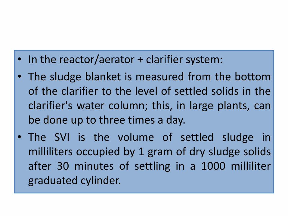
• In the reactor/aerator + clarifier system:
• The sludge blanket is measured from the bottomof the clarifier to the level of settled solids in theclarifier's water column; this, in large plants, canbe done up to three times a day.
• The SVI is the volume of settled sludge inmilliliters occupied by 1 gram of dry sludge solidsafter 30 minutes of settling in a 1000 millilitergraduated cylinder.

• The MCRT is the total mass (lbs) of mixedliquor suspended solids in the aerator andclarifier divided by the mass flow rate (lbs/day)of mixed liquor suspended solids leaving asWAS and final effluent
• The F/M is the ratio of food fed to themicroorganisms each day to the mass ofmicroorganisms held under aeration.
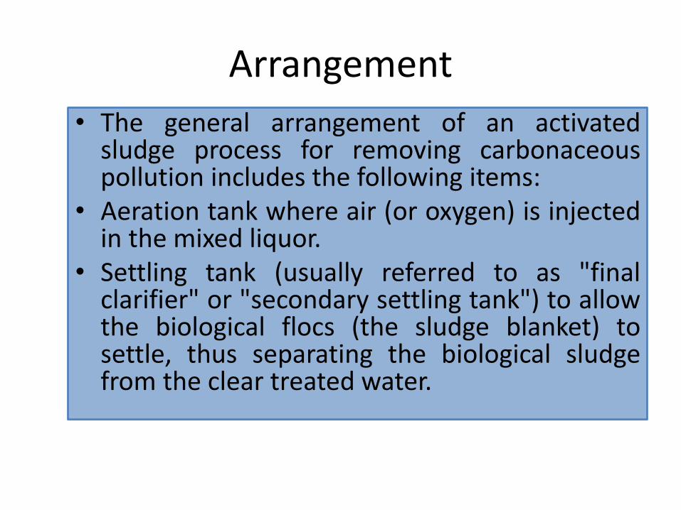
Arrangement
• The general arrangement of an activatedsludge process for removing carbonaceouspollution includes the following items:
• Aeration tank where air (or oxygen) is injectedin the mixed liquor.
• Settling tank (usually referred to as "finalclarifier" or "secondary settling tank") to allowthe biological flocs (the sludge blanket) tosettle, thus separating the biological sludgefrom the clear treated water.

• Treatment of nitrogenous matter orphosphate involves additional steps wherethe mixed liquor is left in anoxic condition(meaning that there is no residual dissolvedoxygen).

General arrangement of an activated sludge process

Two-stage nitrifying process
• In a two-stage nitrifying process , the firststage removes most of the carbonaceousorganic matter and the second stage oxidizesthe ammonia. Typically, nitrification systemshave lower F:M ratios than systems designedfor CBOD removal alone.

Two-stage nitrifying process

Solids Handling control is a first step
•Plant Return Flows are High in BOD and Ammonia
•It inhibits Nitrification and Exceed Nitrification Capability of plant
So we must ,•Return plant flow Slowly
• In Low Quantities•At Low Loading Times
Operational Controls for Nitrification

Air Requirements must be controlled
1.5 lbs of O2 / lb of Biological oxygen demand
4.6 lbs of O2 / lb of Total kaldejhal Nitrogen
Aerobic Reaction Time Must Be Long Enough……….> 5 hrs.

F:M (food to mass) Ratio Must Be Low Enough(< 0.25)
BOD Removal is next step
in Aeration Tank DO (dissolved oxygen) must be increased up to 3 - 5 mg/L
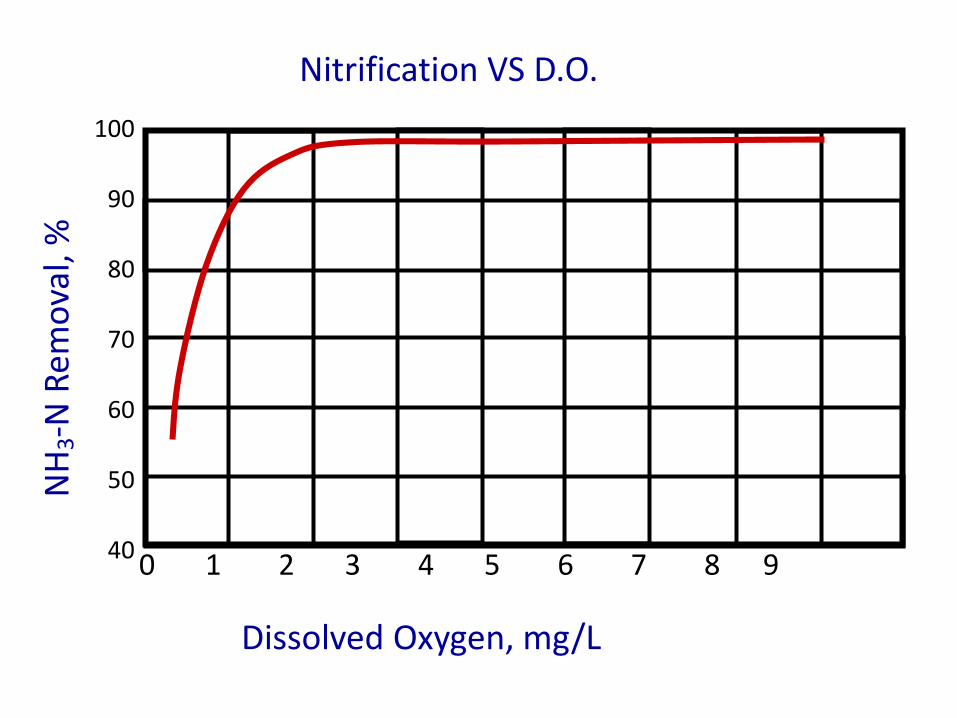
Nitrification VS D.O.N
H3-N
Rem
ova
l, %
Dissolved Oxygen, mg/L
0 1 2 3 4 5 6 7 8 9
100
90
80
70
60
50
40

Effluent BOD Vs % NH3-N Removal
Effluent BOD, mg/L
0 10 20 30 40 50 60 70 80
NH
4-N
Rem
ova
l, %
100
90
80
70
60
50
40
30
20
10
0

Temperature
Substrate concentration
Dissolved oxygen (DO)
pH
Toxic & inhibitory substance
Factors Affecting Nitrification

Nit
rifi
er G
row
th R
ate
0 5 10 15 20 25 30 35 40
4.0
3.5
3.0
2.5
2.0
1.5
1.0
0.5
0.0
Temperature, oC
Effect of Temperature on NitrificationLower the Temperature, Slower will be the growth rate of Nitrifier

90 % Nitrification requires Minimum of 59 Degrees F. (15oC)
Below 50 Degrees F. (10 oC) Maximum of 50 % Nitrification can be
expected only
Ideal Temperature is between 30oC and 35oC (86oF and 95oF)

(Ammonium bicarbonate)NH4HCO3 + O2 HNO3 (nitric acid) + H2O + CO2
7 mg Alkalinity is Destroyed Per mg NH3-N Oxidiation
Chemicals Added For Phosphorus Removal Also Destroy Alkalinity
Adequate Alkalinity is required Effluent Above 50 mg/L
Influent Above 150 mg/L5.3 - 13.5 lbs of Alkalinity is added per lb Fe 6.0 - 9.0 lbs of Alkalinity id added per lb Al
pH will decrease If Not Enough Alkalinity is PresentNitrifiers are pH SensitiveOptimum pH for Nitrosomonas 7.5 & 8.5 for Nitrobacter
Effect of alkalinity on Nitrification

pH VS Nitrification Rate at 68 oF
pH
6.0 6.5 7.0 7.5 8.0 8.5 9.0 9.5 10.0
100908070605040302010
0% o
f M
ax N
itri
fica
tio
n R
ate

Cyanide, thiourea, phenol and heavy metal, nitrous acid and free ammonia can inhibit nitrifying bacteria.
Nitrification occur only when DO level is 1.0 mg/L or more.