nirzar
TRANSCRIPT

TEMPERATURE CONTROL
Nikhil Parmar
Kajal Patel
Nirzar Thakkar
1
A PROJECT REPORT
ON
TEMPERATURE SENSOR
Guided by: Prepared by:
Mr. NIRAV MAKWANA PARMAR NIKHIL .N. (Roll no :) 35
PATEL KAJAL .P. (Roll no :) 41
THAKKAR NIRZAR .A. (Roll no :) 60
DEPARTMENT OF BIO-MEDICAL ENGINEERING
GOVT. POLYTECHNIC, GANDHINAGAR
SEC-26

TEMPERATURE CONTROL
Nikhil Parmar
Kajal Patel
Nirzar Thakkar
2
GOVT. POLYTECHNIC, GANDHINAGAR
SECTOR-26
CERTIFICATE
T O W H O M S O E V E R I T M A Y C O N C E R N
This is to certify that Mr. / Ms. PARMAR NIKHIL NARENDRABHAI of
semester VI (Biomedical Engg.) has satisfactorily completed his/her seminar work titled
“TEMPERATURE SENSOR” in partial fulfillment of requirement of Diploma in
biomedical Engineering from Gujarat technological university , in the year 2011.
Guided by: H.O.D Mr. NIRAV MAKWANA BIOMEDICAL DEPT.
TEMPERATURE CONTROL
Nikhil Parmar
Kajal Patel
Nirzar Thakkar
3
GOVT. POLYTECHNIC, GANDHINAGAR
SECTOR-26
CERTIFICATE
T O W H O M S O E V E R I T M A Y C O N C E R N
This is to certify that Mr. / Ms. PATEL KAJAL PRAVINBHAI of semester VI
(Biomedical Engg.) has satisfactorily completed his / her seminar work titled
“TEMPERATURE SENSOR” in partial fulfillment of requirement of Diploma in
Biomedical Engineering from Gujarat technological university, in the year 2011.
Guided by: H.O.D Mr. NIRAV MAKWANA BIOMEDICAL DEPT.

TEMPERATURE CONTROL
Nikhil Parmar
Kajal Patel
Nirzar Thakkar
4
GOVT. POLYTECHNIC, GANDHINAGAR
SECTOR-26
CERTIFICATE
T O W H O M S O E V E R I T M A Y C O N C E R N
This is to certify that Mr. / Ms. THAKKAR NIRZAR ARAVIND of semester IV
(Biomedical Engg.) has satisfactorily completed his / her seminar work titled
“TEMPERATURE SENSOR” in partial fulfillment of requirement of Diploma in
Biomedical Engineering from Gujarat technological university, in the year 2011.
Guided by: H.O.D Mr. NIRAV MAKWANA BIOMEDICAL DEPT.
TEMPERATURE CONTROL
Nikhil Parmar
Kajal Patel
Nirzar Thakkar
5
ABSTRACT
Temperature is most important parameter in these world everything emit heat in the form
of infrared. By measuring this parameter and manipulating the same adds various
advantages to our day to day life.
LM 35 temperature sensor has ability to detect the temperature from outside world
without any programmable resistor, to display the temperature in user defined values it
need to be processed in microcontroller which needs digital signals which is achieved by
ADC0804, a regulator IC 7805 is used to regulate the voltage between 7V-35V.
It can be interfaced with various devices like Air conditioners, fans heaters etc. to do the
desire task according to the application.
TEMPERATURE CONTROL
Nikhil Parmar
Kajal Patel
Nirzar Thakkar
6
ACKNOWLEDGEMENT
This is humble attempt to thank all those who have supported us all the way through our
project directly or indirectly.
We are thankful to all our facilities that were always helpful to us during the project
development. And amongst them we are especially thankful to Mr. N.D Makwana who
motivated us for facing the problems and helped in uncovering the problem.
We are thankful to Ms. Maitri Dave without whom the application was virtually
impossible. It was their kindness that they give us their time and provides us the
necessary information which was very important for the completions of project.
We hearty thank our all friends for their valuable support to us. Once again we would like
to thank those entire people for their invaluable support to us in our project.
TEMPERATURE CONTROL
Nikhil Parmar
Kajal Patel
Nirzar Thakkar
7
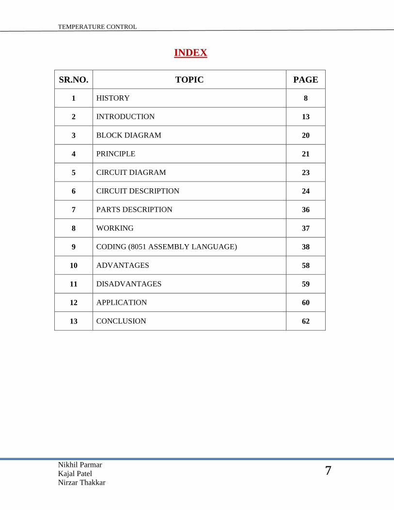
INDEX
SR.NO. TOPIC PAGE
1 HISTORY 8
2 INTRODUCTION 13
3 BLOCK DIAGRAM 20
4 PRINCIPLE 21
5 CIRCUIT DIAGRAM 23
6 CIRCUIT DESCRIPTION 24
7 PARTS DESCRIPTION 36
8 WORKING 37
9 CODING (8051 ASSEMBLY LANGUAGE) 38
10 ADVANTAGES 58
11 DISADVANTAGES 59
12 APPLICATION 60
13 CONCLUSION 62
TEMPERATURE CONTROL
Nikhil Parmar
Kajal Patel
Nirzar Thakkar
8
HISTORY
A Brief History of Temperature
Temperature is by far the most measured parameter. It impacts the physical, chemical and
biological world in numerous ways. Yet, a full appreciation of the complexities of
temperature and its measurement has been relatively slow to develop.
Intuitively, people have known about temperature for a long time: fire is hot and snow is
cold. Greater knowledge was gained as man attempted to work with metals through the
bronze and iron ages. Some of the technological processes required a degree of control
over temperature, but to control temperature you need to be able to measure what you are
controlling.
Early temperature measurement: Galileo
Until about 260 years ago temperature measurement was very subjective. For hot metals
the color of the glow was a good indicator. For intermediate temperatures, the impact on
various materials could be determined. For example does the temperature melt sulphur,
lead or wax, or boil water?
In other words a number of fixed points could be defined, but there was no scale or any
way to measure the temperature between these points. It is, however possible that there is
a gap in the recorded history of technology in this regard as it is difficult to believe that
the Egyptians, Assyrians, Greeks, Romans or Chinese did not measure temperatures in
some way.
Galileo invented the first documented thermometer in about 1592.
It was an air thermometer consisting of a glass bulb with a long tube attached.
TEMPERATURE CONTROL
Nikhil Parmar
Kajal Patel
Nirzar Thakkar
9
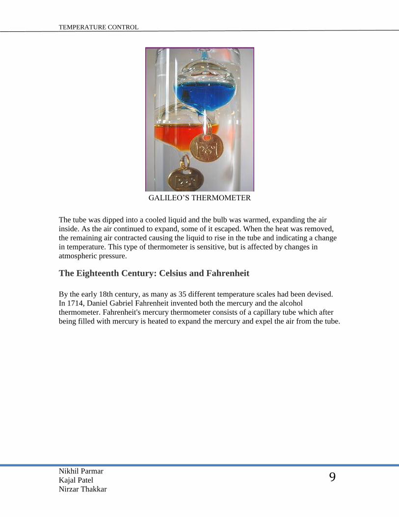
GALILEO’S THERMOMETER
The tube was dipped into a cooled liquid and the bulb was warmed, expanding the air
inside. As the air continued to expand, some of it escaped. When the heat was removed,
the remaining air contracted causing the liquid to rise in the tube and indicating a change
in temperature. This type of thermometer is sensitive, but is affected by changes in
atmospheric pressure.
The Eighteenth Century: Celsius and Fahrenheit
By the early 18th century, as many as 35 different temperature scales had been devised.
In 1714, Daniel Gabriel Fahrenheit invented both the mercury and the alcohol
thermometer. Fahrenheit's mercury thermometer consists of a capillary tube which after
being filled with mercury is heated to expand the mercury and expel the air from the tube.
TEMPERATURE CONTROL
Nikhil Parmar
Kajal Patel
Nirzar Thakkar
10
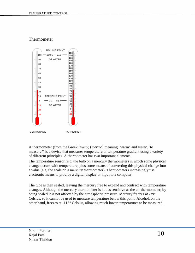
Thermometer
A thermometer (from the Greek θερμός (thermo) meaning "warm" and meter, "to
measure") is a device that measures temperature or temperature gradient using a variety
of different principles. A thermometer has two important elements:
The temperature sensor (e.g. the bulb on a mercury thermometer) in which some physical
change occurs with temperature, plus some means of converting this physical change into
a value (e.g. the scale on a mercury thermometer). Thermometers increasingly use
electronic means to provide a digital display or input to a computer.
The tube is then sealed, leaving the mercury free to expand and contract with temperature
changes. Although the mercury thermometer is not as sensitive as the air thermometer, by
being sealed it is not affected by the atmospheric pressure. Mercury freezes at -39°
Celsius, so it cannot be used to measure temperature below this point. Alcohol, on the
other hand, freezes at -113° Celsius, allowing much lower temperatures to be measured.
TEMPERATURE CONTROL
Nikhil Parmar
Kajal Patel
Nirzar Thakkar
11
At the time, thermometers were calibrated between the freezing point of salted water and
the human body temperature. (Salt added to crush wet ice produced the lowest artificially
created temperatures at the time). The common Flemish thermometers of the day divided
this range into twelve points. Fahrenheit further subdivided this range into ninety-six
points, giving his thermometers more resolution and a temperature scale very close to
today's Fahrenheit scale. (In fact there appeared to have been between 15 and 20 different
temperature scales at this time, determined by nationality and application.)
Later in the 18th century, Anders Celsius realized that it would be advantageous to use
more common calibration references and to divide the scale into 100 increments instead
of 96. He chose to use one hundred degrees as the freezing point and zero degrees as the
boiling point of water. Sensibly the scale was later reversed and the Centigrade scale was
born.
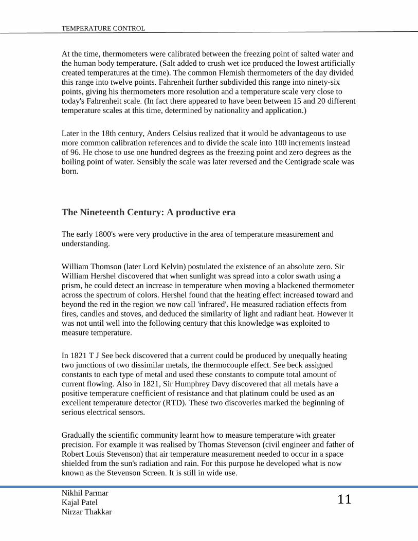
The Nineteenth Century: A productive era
The early 1800's were very productive in the area of temperature measurement and
understanding.
William Thomson (later Lord Kelvin) postulated the existence of an absolute zero. Sir
William Hershel discovered that when sunlight was spread into a color swath using a
prism, he could detect an increase in temperature when moving a blackened thermometer
across the spectrum of colors. Hershel found that the heating effect increased toward and
beyond the red in the region we now call 'infrared'. He measured radiation effects from
fires, candles and stoves, and deduced the similarity of light and radiant heat. However it
was not until well into the following century that this knowledge was exploited to
measure temperature.
In 1821 T J See beck discovered that a current could be produced by unequally heating
two junctions of two dissimilar metals, the thermocouple effect. See beck assigned
constants to each type of metal and used these constants to compute total amount of
current flowing. Also in 1821, Sir Humphrey Davy discovered that all metals have a
positive temperature coefficient of resistance and that platinum could be used as an
excellent temperature detector (RTD). These two discoveries marked the beginning of
serious electrical sensors.
Gradually the scientific community learnt how to measure temperature with greater
precision. For example it was realised by Thomas Stevenson (civil engineer and father of
Robert Louis Stevenson) that air temperature measurement needed to occur in a space
shielded from the sun's radiation and rain. For this purpose he developed what is now
known as the Stevenson Screen. It is still in wide use.
TEMPERATURE CONTROL
Nikhil Parmar
Kajal Patel
Nirzar Thakkar
12
The late 19th century saw the introduction of bimetallic temperature sensor. These
thermometers contain no liquid but operate on the principle of unequal expansion
between two metals. Since different metals expand at different rates, one metal that is
bonded to another, will bend in one direction when heated and will bend in the opposite
direction when cooled (hence the term Bimetallic Thermometer or BiMets). This bending
motion is transmitted, by a suitable mechanical linkage, to a pointer that moves across a
calibrated scale. Although not as accurate as liquid in glass thermometers, BiMets are
hardier, easy to read and have a wider span, making them ideal for many industrial
applications.
The 20th
Century: Further discovery, refinement and recognition
The 20th century has seen the discovery of semiconductor devices, such as: the
thermistor, the integrated circuit sensor, a range of non-contact sensors and also fiber-
optic temperature sensors. Also, Lord Kelvin was finally rewarded for his early work in
temperature measurement. The increments of the Kelvin scale were changed from
degrees to Kelvin’s. Now we no longer say "one-hundred degrees Kelvin;" we instead
say "one-hundred Kelvin’s". The "Centigrade" scale was changed to the "Celsius" scale,
in honour of Anders Celsius.
The 20th century also saw the refinement of the temperature scale. Temperatures can now
be measured to within about 0.001°C over a wide range, although it is not a simple task.
The most recent change occurred with the updating of the International Temperature
Scale in 1990 to the International Temperature Scale of 1990 (ITS-90). This document
also covers the recent history of temperature standards.

TEMPERATURE CONTROL
Nikhil Parmar
Kajal Patel
Nirzar Thakkar
13
INRODUCTION
Temperature sensors:
Temperature Sensors are the devices which are used to measure the temperature of an
object.
These sensors sense the temperature and generate output signals in one of the two forms:
change in voltage or change in resistance. In order to select a sensor for a particular
application - accuracy, range of temperature, response time and environment are
considered.
Temperature sensors are categorized into two types:
(i) Contact type sensors
(ii) Non-Contact type sensors
1. Contact type sensors: These measure their own temperature i.e., they are in contact with the metal and will be
in thermal equilibrium.
Thermocouples Resistive temperature devices
Thermocouple Temperature Measurement Sensors:
Thermocouple Temperature Measurement Sensors
Principle of operation:
Thermocouples work on the principle of See beck effect. They are available in bead type
or probe type construction. They consist of two junctions: cold junction and hot junction.
The voltage developed between two junctions is called See beck voltage. Voltage is in
the order of mill volts. They generate energy in the order of microwatts-mill watts.

TEMPERATURE CONTROL
Nikhil Parmar
Kajal Patel
Nirzar Thakkar
14
2. Non-Contact type Sensors:
These infer temperature by measuring the thermal radiations emitted by the material.
IR thermometers is the example of Non-contact type temperature sensor, these measure
the temperature by detecting the infrared energy emitted by the material. -This consists of
a lens which senses the IR signal and converts it into electrical signal which is displayed
in temperature units. -These are applied when the object is moving, surrounded by EM
field or when a fast response is required.
Temperature sensing can also be done through special type of sensors just like LM 35
this sensor is interface with 8051 microcontroller to sense the temperature and also
control the process.
TEMPERATURE CONTROL
Nikhil Parmar
Kajal Patel
Nirzar Thakkar
15
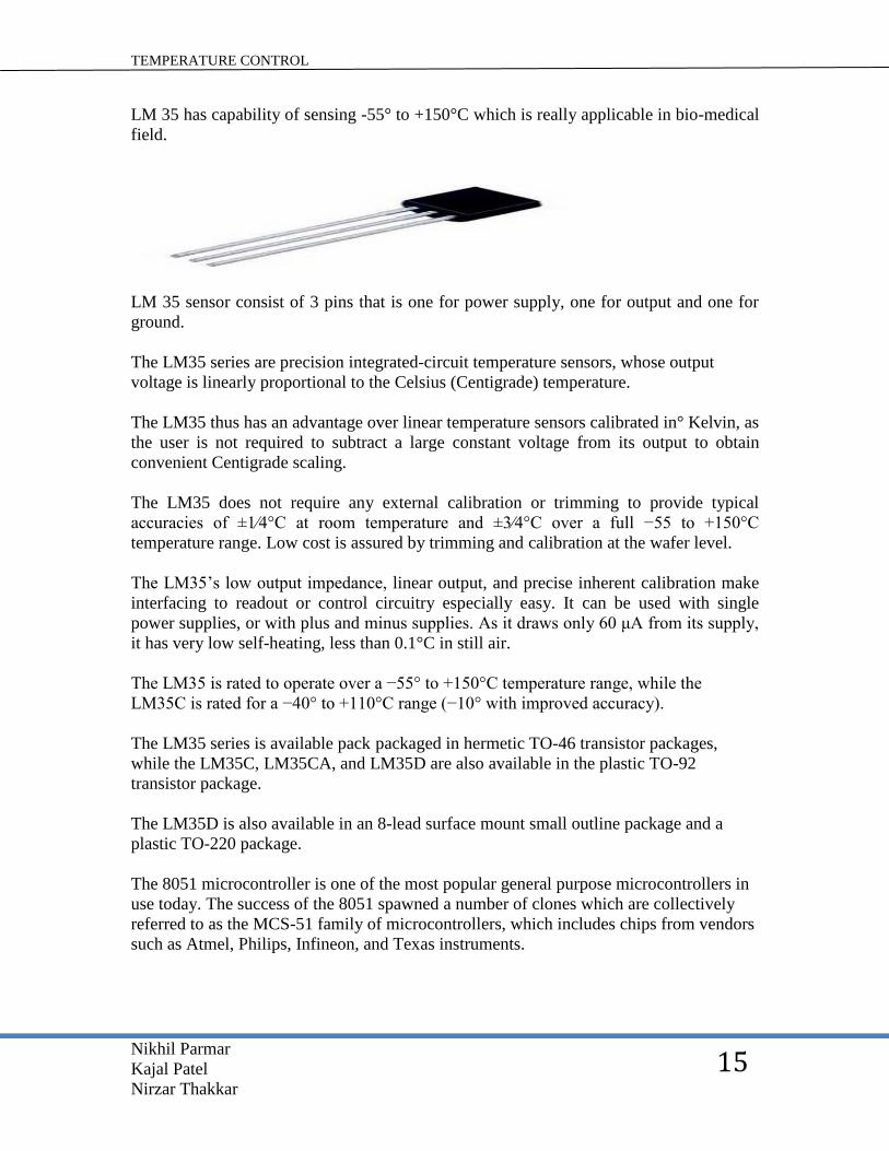
LM 35 has capability of sensing -55° to +150°C which is really applicable in bio-medical
field.
LM 35 sensor consist of 3 pins that is one for power supply, one for output and one for
ground.
The LM35 series are precision integrated-circuit temperature sensors, whose output
voltage is linearly proportional to the Celsius (Centigrade) temperature.
The LM35 thus has an advantage over linear temperature sensors calibrated in° Kelvin, as
the user is not required to subtract a large constant voltage from its output to obtain
convenient Centigrade scaling.
The LM35 does not require any external calibration or trimming to provide typical
accuracies of ±1⁄4°C at room temperature and ±3⁄4°C over a full −55 to +150°C
temperature range. Low cost is assured by trimming and calibration at the wafer level.
The LM35’s low output impedance, linear output, and precise inherent calibration make
interfacing to readout or control circuitry especially easy. It can be used with single
power supplies, or with plus and minus supplies. As it draws only 60 μA from its supply,
it has very low self-heating, less than 0.1°C in still air.
The LM35 is rated to operate over a −55° to +150°C temperature range, while the
LM35C is rated for a −40° to +110°C range (−10° with improved accuracy).
The LM35 series is available pack packaged in hermetic TO-46 transistor packages,
while the LM35C, LM35CA, and LM35D are also available in the plastic TO-92
transistor package.
The LM35D is also available in an 8-lead surface mount small outline package and a
plastic TO-220 package.
The 8051 microcontroller is one of the most popular general purpose microcontrollers in
use today. The success of the 8051 spawned a number of clones which are collectively
referred to as the MCS-51 family of microcontrollers, which includes chips from vendors
such as Atmel, Philips, Infineon, and Texas instruments.
TEMPERATURE CONTROL
Nikhil Parmar
Kajal Patel
Nirzar Thakkar
16
ABOUT LM35 SENSOR
The LM 35 series are precision integrated circuit temperature sensors whose output
voltage is linearly proportional to the Celsius temperature.
LM 35 does not require any external calibration or trimming to provide typical accuracies
of +-1/4°C at room temperature and +-1/4°C over a full -55°C to +150°C.
LM 35 FEATURES
1. -Calibrated directly in Celsius.
2. -Linear + 10.0 mV/°C scale factor.
3. -0.5°C accuracy guarantee (at +25°C).
4. -Rated for full -55°C to 150°C range.
5. -Suitable for remote applications.
6. -Low cost due to wafer level trimming
7. -Operates from 4-30Volts
8. -Less than 60 micro Ampere current drain
9. -Low self-heating 0.08°C in still air
10. -Nonlinearity only +-1/4° C typical
11. -Low impedance output, 0.10 nm for 1mA load
TEMPERATURE CONTROL
Nikhil Parmar
Kajal Patel
Nirzar Thakkar
17
ABOUT THE MICROCONTROLLER
The 8051 is an 8-bit microcontroller which means that most available operations are
limited to 8-bits. There are 3 basic “sizes” of the 8051: short, standard, and extended.
The short and standard chips are often available in DIP (dual in package) form, but the
extended 8051 model often have a different form factor, and are not “drop in
compatible”. All these thongs are called 8051 because they can all be programmed using
8051 assembly language, and they can all share certain features (although the different
models all have their own special features)
Some of the features that have made the 8051 popular are:
1. 64 bits on chip program memory
2. 128 bytes on chip data memory (RAM)
3. 4 register banks
4. 128 user defined software flags
5. 8-bit data bus
6. 16-bit address bus
7. 32 general purpose register each of 8 bits
8. 16 bit timers (usually 2, but may have more, or less)
9. 3 internal and d2 external interrupts
10. Bit as well as byte addressable RAM area of 16 bytes.
11. Four 8-bit ports,(short models have two-8 bit ports).
12. 16-bit program counter and data pointer.
13. 1 microsecond instruction cycle with 12 MHz crystal.
8051 models may also have a number of special, model-specific features such as UARTs,
ADC, opAmps, etc.
TYPICAL APPLICATION 8051 chips are used in a wide variety of control systems.
1. Telecom application
2. Robotics
3. The automotive industry.
By some estimates, 8051 family chips make up over 50% of the embedded chip market.

TEMPERATURE CONTROL
Nikhil Parmar
Kajal Patel
Nirzar Thakkar
18
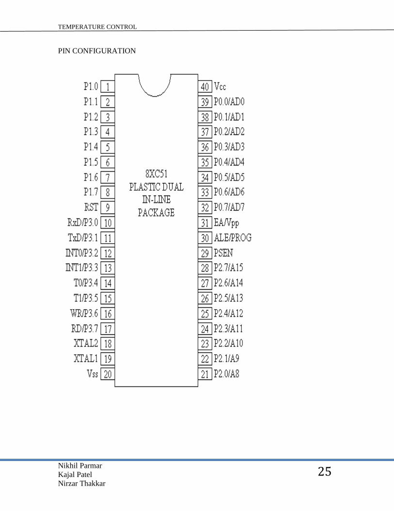
BASIC PINS
Pin 9:- pin 9 is the reset pin which is used to reset the microcontroller’s internal registers
and ports upon starting up. (Pin should be held high for 2 machine cycles.)
Pin 18 & 19:-the 8051 has a built-in oscillator amplifier hence we need to connect a
crystal at these pins to provide clock pulses to the circuit.
Pin 40 & 20:-pins 40 & 20 are Vcc and ground respectively. The 8051 chip needs +5V
500mA to function properly, although there are lower powered versions like the Atmel
2051which is a scaled down version of the 8051 which runs on +3V.
Pins 29, 30 & 31:-as described in the features of the 8051, this chip contains a built in
flash memory. In order to program this we need to supply a voltage of +12V at pin 31. if
external memory is connected then pin 31, also called EA/UVP, should be connected to
ground to indicate the presence of external memory. Pin 30 is called ALE (address latch
enable), which is used when multiple memory chips are connected to the controller and
only one of them needs to be selected. Pin 29 is called PSEN. This is “program store
enable”. In order to use the external memory it is required to provide the low voltage (0)
on both PSEN and EA pins.
PORTS There are 4 8-bit ports P0, P1, P2 and P3.
Port P1 :-( pins 1 to 8) the port P1 is a general purpose input/output port which can be
used for variety of interfacing tasks. The other ports P0, P2, P3 have dual roles or
additional functions associated with them based upon the context of their usage.
Port P3 :-(pins 10-17)port P3 acts as a normal io port, but portP3 has additional functions
such as, serial transmit and receive pins, 2 external interrupt pins, 2 external counter
inputs, read and write pins for memory access.
Port P2:- (pins 21 to 28) port P2 can also be used as a general purpose 8 bit port when no
external memory is present, but if external memory access is required then port P2 will
act as an address bus in conjunction with port P0 to access external memory. Port P2 acts
as A8-A15.
Pin P0:-(pins 32 to 39)port P0 can be used as a general purpose 8 bit port when no
external memory is present, but if external memory access is required then port P0 acts as
a multiplexed address and data bus that can be used to access external memory in
conjunction with port P2. P0 acts as a AD0-AD7.

TEMPERATURE CONTROL
Nikhil Parmar
Kajal Patel
Nirzar Thakkar
19
OSCILLATOR CIRCUITS
The 8051 requires the existence of an external oscillating circuit.
The oscillator circuit usually runs around 12MHz, although the 8051 (depending on
which specific model) is capable of running at a maximum of 40MHz.
Each machine cycle in the 8051 is 12 clock cycles, giving an effective cycle rate at 1MHz
(for a 12MHz clock) to 3.33MHz (for the maximum 40 MHz clock).

TEMPERATURE CONTROL
Nikhil Parmar
Kajal Patel
Nirzar Thakkar
20
BLOCK DIAGRAM
Here LM 35 temperature works as transducer which senses the temperature and transmits
the analog signal into
The analog to digital converter converts the analog signals that transmited by LM 35
sensor which is then transmited into microcontroller for further processing
The processed signals are are then displayed as output.
Or this signals are manipulated as devices driving signals for the devices of interest.

TEMPERATURE CONTROL
Nikhil Parmar
Kajal Patel
Nirzar Thakkar
21
PRINCIPLE
The temperature sensing in incubator works on the principle of non contact type
temperature sensing as it includes LM35 temperature sensor which works on the same
principle, the sensor is connected with microcontroller which in turns display the
temperature on display as well as detect the preset values which is predefined as
threshold for microcontroller which warns the observer if the same goes beyond the
threshold values.
R5 and C3 are used for capacitive load compensation. • The ADC804 has 8-bit resolution
with a maximum of 256 steps and the LM35 produces 10mV for every degree of
temperature change.

TEMPERATURE CONTROL
Nikhil Parmar
Kajal Patel
Nirzar Thakkar
22
•We will do calibration such that, for temperature range of 0 to 100°C, voltage in at the
input of ADC will be 0 to 2.56 v.
•we need to set Vref/2 = 1.28Vso step size will be 2560mv/256 = 10mval so for every
degree change in temp.
LM35 output changes by 10mv ,so every degree change in temp. will produce 1 unit
change in digital out of ADC
•Thus resolution of our system will be 1deg C°, which is smallest temperature that we
can measure with this system.
TEMPERATURE CONTROL
Nikhil Parmar
Kajal Patel
Nirzar Thakkar
23
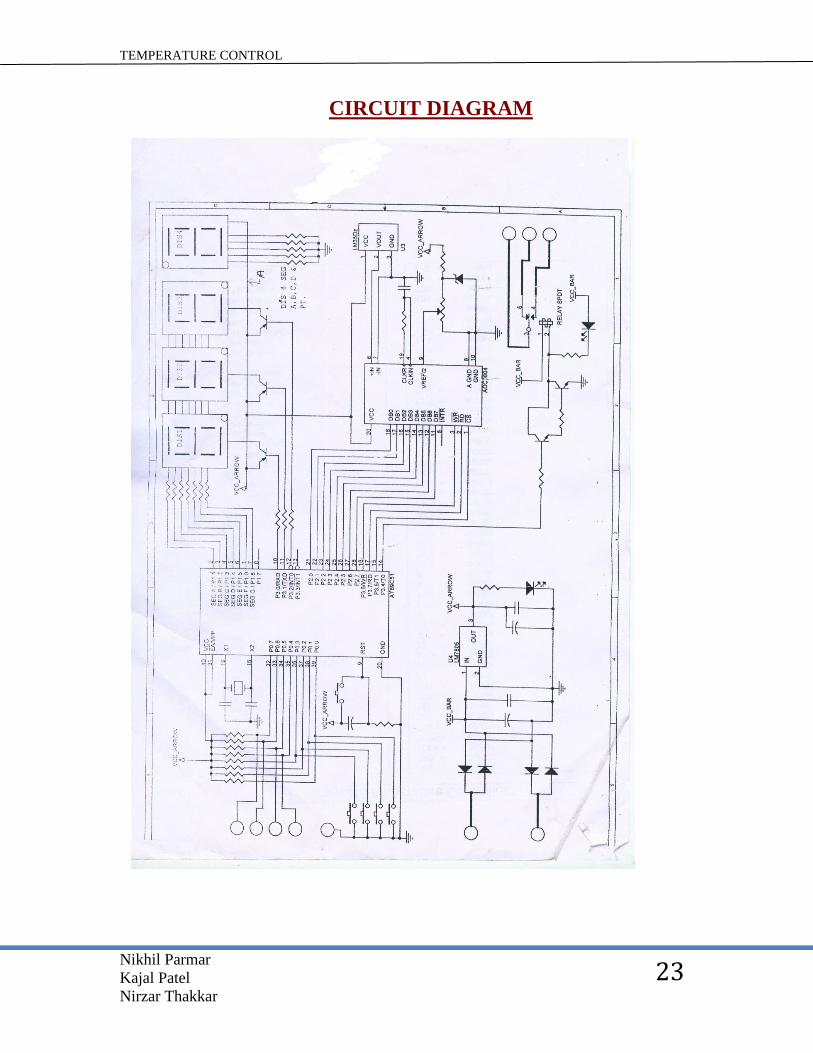
CIRCUIT DIAGRAM

TEMPERATURE CONTROL
Nikhil Parmar
Kajal Patel
Nirzar Thakkar
24
CIRCUIT DESCRIPTION
POWER SUPPLY:-
The circuit operates off a simple power supply using an IC 7805 regulator. A 12V ac is
rectified and filtered by using a bridge rectifier and filter capacitor.
On the +12V rail, a 7805 regulator is used to regulate the output to a stable 5V.
Bridge rectifier is use to convert 12 AC into 12 DC voltages. Two supply voltages are
required for the circuit.
A 12V AC from transformer is connected to bridge rectifier (D1-D4). All ICs are
supplied with a regulated 5V from a LM 7805 fixed voltage regulator.
The unregulated voltage of approximately 12V is required for the relay driving circuit.
AT89C51 MICRO CONTROLLER:-
The AT89C51 is a low power, high performance CMOS 8-bit microcontroller with 4K
bytes of flash programmable and erasable read only memory (PEROM).
The device is manufactured using Atmel’s high-density non volatile memory technology
and compatible with the industry-standard MCS-51 instruction set and pin out.
The on chip flash allows the programmer. By combining a versatile 8-bit CPU with flash
on a monolithic chip the Atmel AT89C51 is a powerful microcontroller which provides a
highly flexible and cost-effective solution to many embedded control application.
TEMPERATURE CONTROL
Nikhil Parmar
Kajal Patel
Nirzar Thakkar
25
PIN CONFIGURATION

TEMPERATURE CONTROL
Nikhil Parmar
Kajal Patel
Nirzar Thakkar
26
FEATURES:
1. Compatible with MCS-51 products.
2. 4K bytes of in-system reprogrammable flash memory.
3. Fully static operation: 0 Hz to 24MHz.
4. Three-level program memory lock.
5. 128*8 bit internal RAM.
6. 32 programmable IN/OUT lines.
7. Two16-bit time/counter.
8. Six interrupt sources.
9. Programmable serial channel.
10. Low-power idle and power down modes.
TEMPERATURE CONTROL
Nikhil Parmar
Kajal Patel
Nirzar Thakkar
27
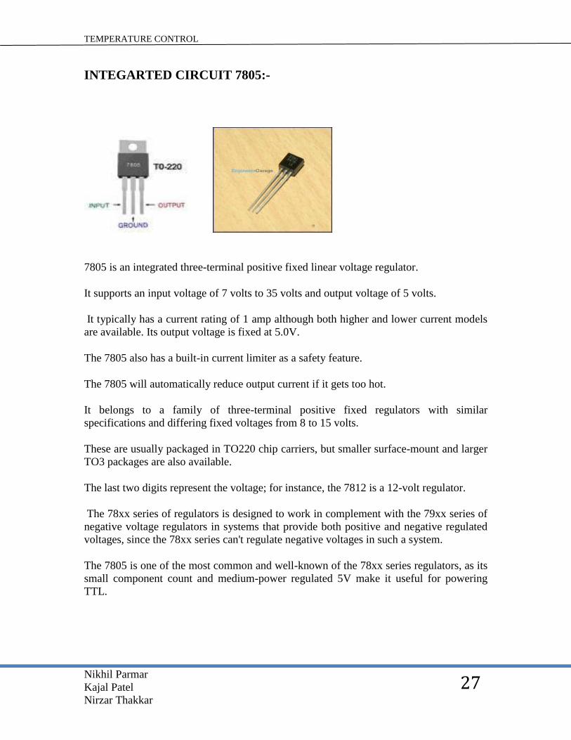
INTEGARTED CIRCUIT 7805:-
7805 is an integrated three-terminal positive fixed linear voltage regulator.
It supports an input voltage of 7 volts to 35 volts and output voltage of 5 volts.
It typically has a current rating of 1 amp although both higher and lower current models
are available. Its output voltage is fixed at 5.0V.
The 7805 also has a built-in current limiter as a safety feature.
The 7805 will automatically reduce output current if it gets too hot.
It belongs to a family of three-terminal positive fixed regulators with similar
specifications and differing fixed voltages from 8 to 15 volts.
These are usually packaged in TO220 chip carriers, but smaller surface-mount and larger
TO3 packages are also available.
The last two digits represent the voltage; for instance, the 7812 is a 12-volt regulator.
The 78xx series of regulators is designed to work in complement with the 79xx series of
negative voltage regulators in systems that provide both positive and negative regulated
voltages, since the 78xx series can't regulate negative voltages in such a system.
The 7805 is one of the most common and well-known of the 78xx series regulators, as its
small component count and medium-power regulated 5V make it useful for powering
TTL.

TEMPERATURE CONTROL
Nikhil Parmar
Kajal Patel
Nirzar Thakkar
28
RESISTOR:
A resistor is a two-terminal electrical or electronic component that opposes an electric
current by producing a voltage drop between its terminals in accordance with Ohm's law:
The electrical resistance is equal to the voltage drop across the resistor divided by the
current through he resistor while the temperature remains the same.
Resistors are used as part of electrical networks and electronic circuits.
Resistors work on the principle called resistance.
Resistance is a property of a material that opposes the flow of electrons in a conducting
material; every matter has its own resistance which varies material to material.
TEMPERATURE CONTROL
Nikhil Parmar
Kajal Patel
Nirzar Thakkar
29
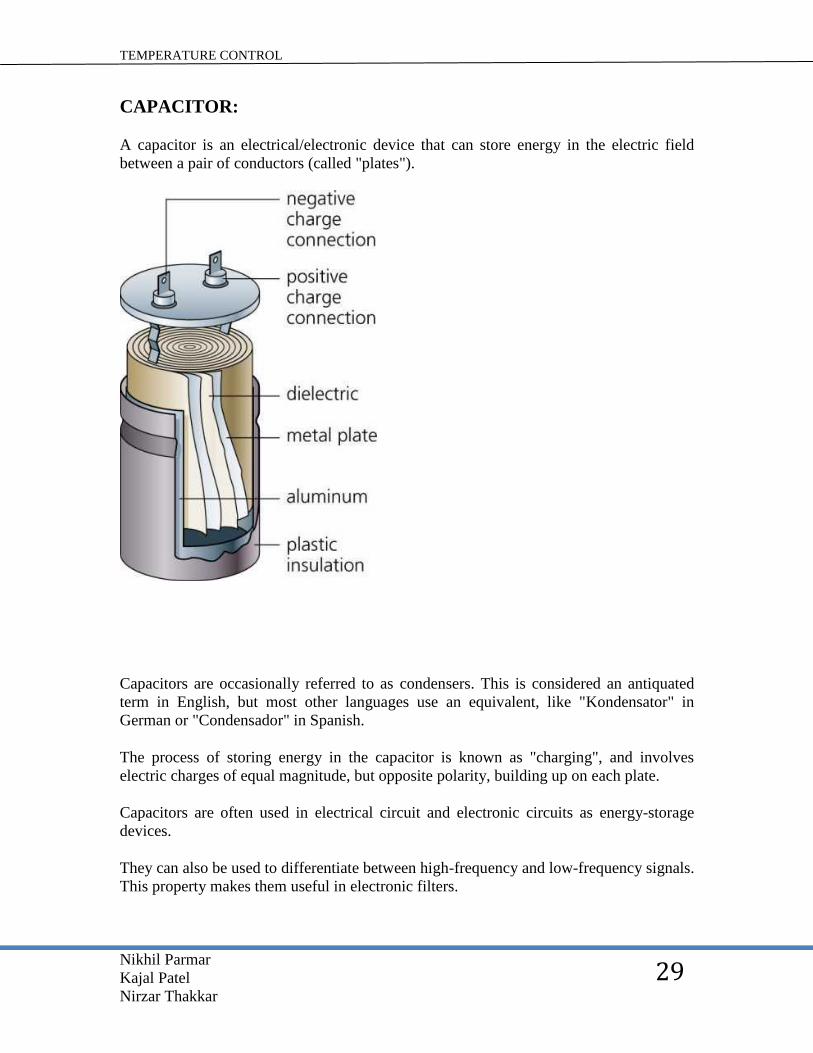
CAPACITOR:
A capacitor is an electrical/electronic device that can store energy in the electric field
between a pair of conductors (called "plates").
Capacitors are occasionally referred to as condensers. This is considered an antiquated
term in English, but most other languages use an equivalent, like "Kondensator" in
German or "Condensador" in Spanish.
The process of storing energy in the capacitor is known as "charging", and involves
electric charges of equal magnitude, but opposite polarity, building up on each plate.
Capacitors are often used in electrical circuit and electronic circuits as energy-storage
devices.
They can also be used to differentiate between high-frequency and low-frequency signals.
This property makes them useful in electronic filters.

TEMPERATURE CONTROL
Nikhil Parmar
Kajal Patel
Nirzar Thakkar
30
RELAY:
A relay is an electrical switch that opens and closes under the control of another electrical
circuit.
In the original form, the switch is operated by an electromagnet to open or close one or
many sets of contacts.
It was invented by Joseph Henry in 1835.
Because a relay is able to control an output circuit of higher power than the input circuit,
it can be considered to be, in a broad sense, a form of an electrical amplifier.
When a current flows through the coil, the resulting magnetic field attracts an armature
that is mechanically linked to a moving contact.
The movement either makes or breaks a connection with a fixed contact.
When the current to the coil is switched off, the armature is returned by a force
approximately half as strong as the magnetic force to its relaxed position.
Usually this is a spring, but gravity is also used commonly in industrial motor starters.
Most relays are manufactured to operate quickly.
In a low voltage application, this is to reduce noise. In a high voltage or high current
application, this is to reduce arcing.
TEMPERATURE CONTROL
Nikhil Parmar
Kajal Patel
Nirzar Thakkar
31
If the coil is energized with DC, a diode is frequently installed across the coil, to dissipate
the energy from the collapsing magnetic field at deactivation, which would otherwise
generate a spike of voltage and might cause damage to circuit components.
Some automotive relays already include that diode inside the relay case. Alternatively a
contact protection network, consisting of a capacitor and resistor in series, may absorb
the surge.
If the coil is designed to be energized with AC, a small copper ring can be crimped to the
end of the solenoid. This "shading ring" creates a small out-of-phase current, which
increases the minimum pull on the armature during the AC cycle.
By analogy with the functions of the original electromagnetic device, a solid-state relay is
made with a thyristor or other solid-state switching device.
To achieve electrical isolation an optocoupler can be used which is a light-emitting diode
(LED) coupled with a photo transistor

TEMPERATURE CONTROL
Nikhil Parmar
Kajal Patel
Nirzar Thakkar
32
LED:
Light Emitting Diodes (LED)
Everyone is familiar with light-emitting diodes (LEDs) from their use as indicator lights
and numeric displays on consumer electronics devices.
New LED materials and improved production processes have produced bright LEDs in
colors throughout the visible spectrum, including white light, with efficacies grater that
incandescent lamps. These brighter, more efficacious, and colorful LEDs move LED
technology into a wider range of lighting applications.
Already a leading light source for exit signs and developing as a popular source for traffic
signals, LEDs also appear in display, decorative, and transportation applications, with
plenty of opportunity for expansion.
Small, lightweight, durable, and with long life, LEDs have the long-term potential to be
the source of choice in many applications, from automotive brake lights to task lights.
What are LEDs and how do they work?
LEDs are solid-state semiconductor devices that convert electrical energy directly into
light.
LED "cold" generation of light leads to high efficacy because most of the energy radiates
in the visible spectrum. Incandescent, and to a lesser extent fluorescent, lamps radiate
much energy in the non-visible spectrum, generating heat as well as light.
TEMPERATURE CONTROL
Nikhil Parmar
Kajal Patel
Nirzar Thakkar
33
Light is generated inside the chip, a solid crystal material, when current flows across the
junction of the different materials. The light-generating chip is quite small, typically 0.25
millimeters square.
The plastic encapsulate and lead frame occupy most of the volume. Presently, the most
commonly used LEDs are the 5 mm LED package.
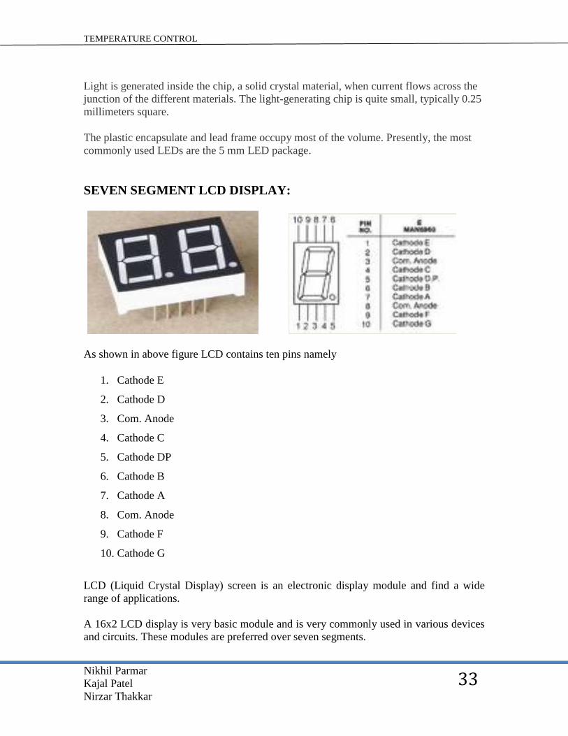
SEVEN SEGMENT LCD DISPLAY:
As shown in above figure LCD contains ten pins namely
1. Cathode E
2. Cathode D
3. Com. Anode
4. Cathode C
5. Cathode DP
6. Cathode B
7. Cathode A
8. Com. Anode
9. Cathode F
10. Cathode G
LCD (Liquid Crystal Display) screen is an electronic display module and find a wide
range of applications.
A 16x2 LCD display is very basic module and is very commonly used in various devices
and circuits. These modules are preferred over seven segments.

TEMPERATURE CONTROL
Nikhil Parmar
Kajal Patel
Nirzar Thakkar
34
TRANSFORMER:
Transformer is a static device that transfers electrical energy from one circuit to another
through inductively coupled.
Conductors -the transformer’s coils. A varying current in the first or primary winding
creates a varying magnetic flux in the transformer’s core and thus a varying magnetic
field through the secondary winding.
This varying magnetic field induces a varying electromotive force (emf) or “voltage” in
the secondary winding. This effect is called mutual induction.
If a load is connected to the secondary, an electric current will flow in the secondary
winding and electrical energy will be transferred from the primary circuit through the
Transformer to the load, in an ideal transformer, the induced voltage in the secondary
winding (Vs) is in proportion to the primary voltage (Vp), and is given by the ratio of the
number of turns in the secondary (Ns) to the number of turns in the primary (Np) as
follow:-
Vs⁄Vp = Ns⁄Np
By appropriate selection of the ratio of turns, a transformer thus allows an alternating
current (AC) voltage to be “stepped up” by making Ns greater than Np or “stepped
down” by making Ns less than Np.
In the vast majority of transformer, the windings are coils wound around a ferromagnetic
core, air core transformers being a notable exception.

TEMPERATURE CONTROL
Nikhil Parmar
Kajal Patel
Nirzar Thakkar
35
TWO PIN PLUG:
Two pin plug is connected with transformer which supply power to transformer which is
connected with circuit and thus power supply is given to circuit via two pin plug, the two
pin plug has one pin for phase and other for neutral.
TEMPERATURE CONTROL
Nikhil Parmar
Kajal Patel
Nirzar Thakkar
36
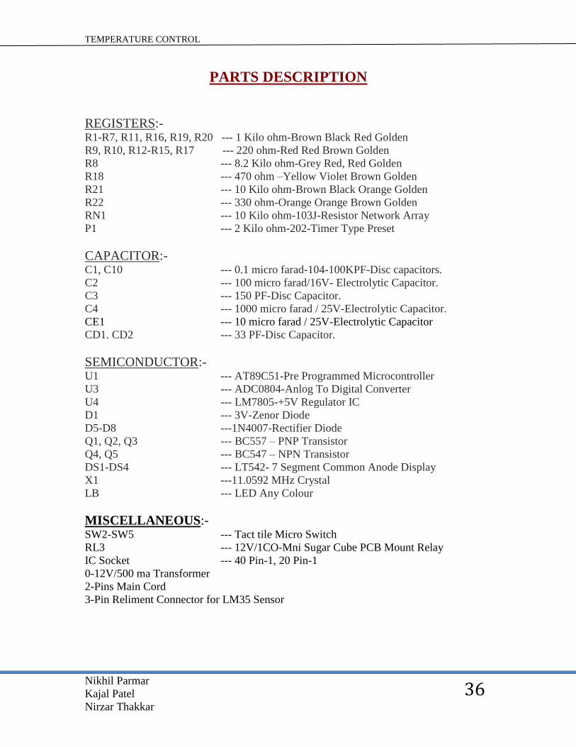
PARTS DESCRIPTION
REGISTERS:- R1-R7, R11, R16, R19, R20 --- 1 Kilo ohm-Brown Black Red Golden
R9, R10, R12-R15, R17 --- 220 ohm-Red Red Brown Golden
R8 --- 8.2 Kilo ohm-Grey Red, Red Golden
R18 --- 470 ohm –Yellow Violet Brown Golden
R21 --- 10 Kilo ohm-Brown Black Orange Golden
R22 --- 330 ohm-Orange Orange Brown Golden
RN1 --- 10 Kilo ohm-103J-Resistor Network Array
P1 --- 2 Kilo ohm-202-Timer Type Preset
CAPACITOR:- C1, C10 --- 0.1 micro farad-104-100KPF-Disc capacitors.
C2 --- 100 micro farad/16V- Electrolytic Capacitor.
C3 --- 150 PF-Disc Capacitor.
C4 --- 1000 micro farad / 25V-Electrolytic Capacitor.
CE1 --- 10 micro farad / 25V-Electrolytic Capacitor
CD1. CD2 --- 33 PF-Disc Capacitor.
SEMICONDUCTOR:- U1 --- AT89C51-Pre Programmed Microcontroller
U3 --- ADC0804-Anlog To Digital Converter
U4 --- LM7805-+5V Regulator IC
D1 --- 3V-Zenor Diode
D5-D8 ---1N4007-Rectifier Diode
Q1, Q2, Q3 --- BC557 – PNP Transistor
Q4, Q5 --- BC547 – NPN Transistor
DS1-DS4 --- LT542- 7 Segment Common Anode Display
X1 ---11.0592 MHz Crystal
LB --- LED Any Colour
MISCELLANEOUS:- SW2-SW5 --- Tact tile Micro Switch
RL3 --- 12V/1CO-Mni Sugar Cube PCB Mount Relay
IC Socket --- 40 Pin-1, 20 Pin-1
0-12V/500 ma Transformer
2-Pins Main Cord
3-Pin Reliment Connector for LM35 Sensor
TEMPERATURE CONTROL
Nikhil Parmar
Kajal Patel
Nirzar Thakkar
37
WORKING
The power supply circuit is used to apply 5V of current supply to components like
capacitor, diode, microcontroller, integrated circuits etc.
This power supply is apply to LCD display
This power supply which is applied to LCD display is controlled by microcontroller
through port 3 say pin number 10,11,12,13 RXD, TXD, INT0 and INT1respectively.
The LCD display is grounded with resistors
Power supply is also applied to integrated circuit or can say vertical circuit LM7805
The temperature is sensed by LM35Dz temperature sensor which is in analog form that is
to be converted into digital form
For such task ADC0804 analog to digital converter is used.
All the 8 pins of port 2 and 4 pins of port3 is used that is write, read, timer are connected
with analog to digital converter.
The input in analog to digital converter is the output generated by LM35Dz temperature
sensor.
This analog to digital converter is controlled by microcontroller it controls the conversion
of signal supplied by temperature sensor in to digital form.
Now the digitized signal is processed and given as the input to LCD display which
generates the output.
The output is displayed as numeric image which continuously gets on/off but human eye
cannot detect that and it seems like lighted number continuously displayed.
The power supply is given to microcontroller through port 0 the switching is provide to
port 0 on 36,37,38,39 pins.
The external devices like Air-conditioners Fans etc. is drive through pin number 14 of
microcontroller which is connected with Relay via two transistors.

TEMPERATURE CONTROL
Nikhil Parmar
Kajal Patel
Nirzar Thakkar
38
CODING (8051 ASSEMBLY LANGUAGE)
The program for displaying the temperature which is sensed by LM35Dz temperature
sensor is necessary to be processed in microcontroller as temperature sensor detects the
analog signal which is to be converted into degree Celsius for that calculation process is
done in microcontroller for that the coding is shown bellow.
globl_convert
globl_main
globl_timer_isr
globl_count1
globl_delay
globl_key
globl_time
globl_pro
globl_opto
globl_v
globl_chipE
globl_buffer
globl_digit
globl_i
globl_chek
globl_rm
globl_ch
globl_x
TEMPERATURE CONTROL
Nikhil Parmar
Kajal Patel
Nirzar Thakkar
39
globl_j
globl_h
globl_g
globl_f
globl_e
globl_d
globl_c
globl_b
globl_a
globl_z
globl_qz
globl_temp
globl_command
globl_flag1
globl_temperature
globl_water
globl_scanLED
globl_chip
globl_distemp
globl_check_temp
globl_keyexe
globl_checkdata

TEMPERATURE CONTROL
Nikhil Parmar
Kajal Patel
Nirzar Thakkar
40
globl_setup
globl_setdown
globl_save
globl_manualOnOff
globl_showOnce
globl_comp
globl_keydelay
globl_pause
P0 = 0x0080
SP =0x0081
_DPL =0x0082
_DPH =0x0083
_PCON =0x0087
_TCON =0x0088
_TMOD =0x0089
_TL0 =0x008a
_TL1 =0x008b
_TH0 =0x008c
_TH1 =0x008d
_P1 =0x0090
_SCON =0x0098
_SBUF =0x0099

TEMPERATURE CONTROL
Nikhil Parmar
Kajal Patel
Nirzar Thakkar
41
_P2 =0x00a0
_IE =0x00a8
_P3 =0x00b0
_IP =0x00b8
_PSW =0x00d0
_ACC =0x00E0
_A =0x00e0
_B =0x00f0
_P0_0 =0x0080
_P0_1 =0x0081
_P0_2 =0x0082
_P0_3 =0x0083
_P0_4 =0x0084
_P0_5 =0x0085
_P0_6 =0x0086
_P0_7 =0x0087
_IT0 =0x0088
_IE0 =0x0089
_ITI =0x008a
_IEI =0x008b
_TR0 =0x008c
_TF0 =0x008d

TEMPERATURE CONTROL
Nikhil Parmar
Kajal Patel
Nirzar Thakkar
42
_TRI =0x008e
_TFI =0x008f
_P1_0 =0x0090
_P1_1 =0x0091
_P1_2 =00x092
_P1_3=0x0093
_P1_4 =0x0094
_P1_5 =0x0095
_P1_6 =0x0096
_P1_7 =0x0097
_RI =0x0098
_TI =0x0099
_RB8 =0x009a
_TB8 = 0x009b
_REN = 0x009c
_SM2=0x009d
_SM1 = 0x009c
_SM3 = 0x009f
_P2_0 = 0x00a0
_P2_1 = 0x00a1
_P2_2 = 0x00a2
_P2_3 = 0x00a3

TEMPERATURE CONTROL
Nikhil Parmar
Kajal Patel
Nirzar Thakkar
43
_P2_4 = 0x00a4
_P2_5 = 0x00a5
_P2_6 = 0x00a6
_P2_7 = 0x00a7
_EX0 = 0x00a8
_ET0 = 0x00a9
_EX1 = 0x00aa
_ET1 = 0x00ab
_ES = 0x00ac
_EA = 0x00af
_P3_0 = 0x00b0
_P3_1 = 0x00b1
_P3_2 = 0x00b2
_P3_3 = 0x00b3
_P3_4 = 0x00b4
_P3_5 = 0x00b5
_P3_6 = 0x00b6
_P3_7 = 0x00b7
_RXD = 0x00b0
_TXD = 0x00b1
_INT0 = 0x00b2
_INT1 = 0x00b3
TEMPERATURE CONTROL
Nikhil Parmar
Kajal Patel
Nirzar Thakkar
44
_T0 = 0x00b4
_T1 = 0x00b5
_WR = 0x00b6
_RD = 0x00b7
_PX0 = 0x00b8
_PT0 = 0x00b9
_PX0 = 0x00ba
_PT1 = 0x00bb
_PS = 0x00bc
_P = 0x00d0
_FL = 0x00d1
_OV = 0x00d2
_RS0 = 0x00d3
_RS1 = 0x00d4
_F0 = 0x00d5
_AC = 0x00d6
_CY = 0x00D7
mov sp#_start_stack-1
lcall mov a,dpl
ljump mov rl,#l_XINIT
mov a,r,l
orl a,#(l_XINIT>>8)

TEMPERATURE CONTROL
Nikhil Parmar
Kajal Patel
Nirzar Thakkar
45
mov r2,#((l_XINIT>>+225)>>8)
mov dptr,#s_XINIT
mov r0,#s_XISEG
mov p2,#(s_XISEG>>8)
movc a,@a+dptr
movx @r0,a
mov p2,#0xFF
mov r0,#I_XSEG
mov a,r0
orl a,#(1_XSEG>>8)
mov r1,#((l_XSEG + 225)>>8)
mov dptr,#s_XSEG
clr a
movx @dptr,a
inc dptr
mov @r0,a
mov _z,#0x00
ar2 = 0x0a
ar3 = 0x0b
ar4 = 0x0c
ar5 = 0x0d
ar6 = 0x0e

TEMPERATURE CONTROL
Nikhil Parmar
Kajal Patel
Nirzar Thakkar
46
ar7 = 0x0f
ar0 = 0x08
ar1 = 0x09
push b
mov psw,#0x08
orl _TH0,#0xDC
pop psw
pop dph
pop b
pop acc
reti
_main: ar2 = 0x02
ar3 = 0x03
ar4 = 0x04
ar5 = 0x05
ar6 = 0x06
ar7 = 0x07
ar0 = 0x00
ar1 = 0x01
mov _pro,#0x01
mov _rm,#0xx01
mov _temp,#0x32

TEMPERATURE CONTROL
Nikhil Parmar
Kajal Patel
Nirzar Thakkar
47
mov _count1,#0x00
mov _chipE,#0x8F
mov _P0,#0xFF
mov _ch,#0x00
slr c
mov a_pro
sub a,#0x03
mov _pro,#0x01
mov a,_pro
cjne a,#0x01
mov a,pro
mov _buffer,#0x00
mov (_buffer + 0x0001),#0x73
mov (_buffer + 0x0002),#0x00
mov _buffer,#0x00
mov (_buffer + 0x0001),#0x31
mov (_buffer + 0x0002),#0x00
mov _buffer,#0x00
mov (_buffer + 0x0001),#0x6D
mov (_buffer + 0x0002),#0x00
mov _buffer,#0x00
mov (_buffer + 0x0001),#0x6F

TEMPERATURE CONTROL
Nikhil Parmar
Kajal Patel
Nirzar Thakkar
48
mov (_buffer + 0x0002),#0x00
mov _buffer,#0x00
mov (_buffer + 0x0001),#0x63
mov (_buffer + 0x0002),#0x00
mov _digit,#0x04
mov r2,#0x00
mov r3,#0x00
clr c
mov a,r2
sub a,#0x03
mov a,r3
xrl a,#0x80
sub a,#0x80
mov a_digit
mov r4,a
mov a,_chipE
anl a,r4
anl a,_opto
mov _P3,a
mov a,r2
add a,#_buffer
mov r0,a
TEMPERATURE CONTROL
Nikhil Parmar
Kajal Patel
Nirzar Thakkar
49
mov ar4,@r0
mov a,r4
cpl a
mov _P1,a
mov dptr,#0x0005
mov _Pl,#0xFF
mov a,_digit
clr c
mov _digit,a
inc r2
inc r3
inc _time
clr a
inc (_time + 1)
clr c
mov a,_time
subb a,#0xF4
mov a,(_time + 1)
sub a,#0x01
clr a
mov (_time + 1)
mov _time,a

TEMPERATURE CONTROL
Nikhil Parmar
Kajal Patel
Nirzar Thakkar
50
inc _chek
clr c
mov a,_chek
sub a,#0x03
mov _chek,#0x01
mov a,_chek
cjne a,#0x01,00106$
mov _chipE,#0x9F
mov a,_chek
cjne a,#0x02,00109$
mov _chipE,#0x01F
:mov b,#0x0A
mov a,_z
div ab
mov r2,b
mov a,r2
mov dptr,#_convert
movc a,@a+dptr
mov r2,a
mov _buffer,r2
mov b_#0x0A
mov a_z

TEMPERATURE CONTROL
Nikhil Parmar
Kajal Patel
Nirzar Thakkar
51
mov r2,a
clr a
mov r3,a
mov (_modsint_PARM_2 + 1)
mov _modsint_PARM_2,#0X0A
mov dpl,r2
mov dph,r3
mov r2,dpl
mov r3,dph
mov a,r2
add a,#_convert
mov dpl,a
mov a,r3
addc a,#(_convert>>8)
mov dph,a
clr a
movc a,@a+dptr
mov r2,a
mov (_buffer + 0x0001),r2
mov b,#0x64
mov a,_z
div ab
TEMPERATURE CONTROL
Nikhil Parmar
Kajal Patel
Nirzar Thakkar
52
mov r2,a
clr a
mov r3,a
mov (_modsint_PARM_2 + 1),a
mov _modsint_PARM_2,#0x0A
mov dpl,r2
mov dph,r3
lcall _modsint
mov r2,dpl
mov r3,dph
mov a,r2
add a,#_convert
mov dpl,a
mov a,r3
addc a,#(_convert>>8)
mov dph,a
clr a
movc a,@a+dptr
mov r2,a
mov (_buffer : 0x0002),r2
_check_temp:
mov _a,#0x01
TEMPERATURE CONTROL
Nikhil Parmar
Kajal Patel
Nirzar Thakkar
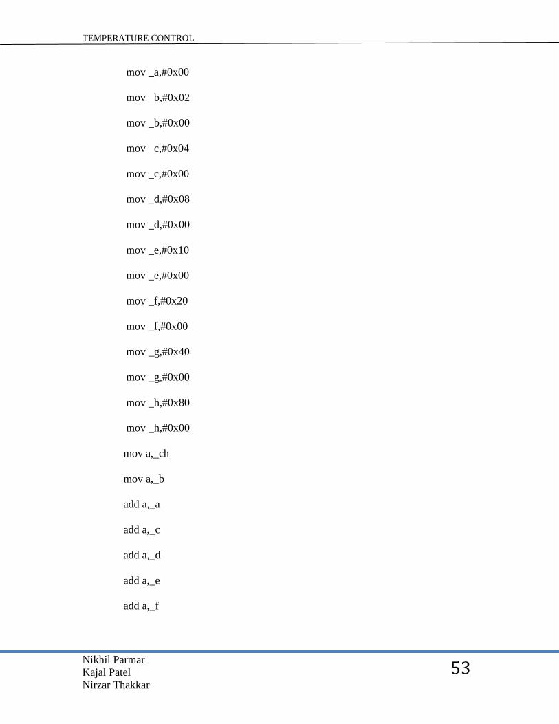
53
mov _a,#0x00
mov _b,#0x02
mov _b,#0x00
mov _c,#0x04
mov _c,#0x00
mov _d,#0x08
mov _d,#0x00
mov _e,#0x10
mov _e,#0x00
mov _f,#0x20
mov _f,#0x00
mov _g,#0x40
mov _g,#0x00
mov _h,#0x80
mov _h,#0x00
mov a,_ch
mov a,_b
add a,_a
add a,_c
add a,_d
add a,_e
add a,_f
TEMPERATURE CONTROL
Nikhil Parmar
Kajal Patel
Nirzar Thakkar
54
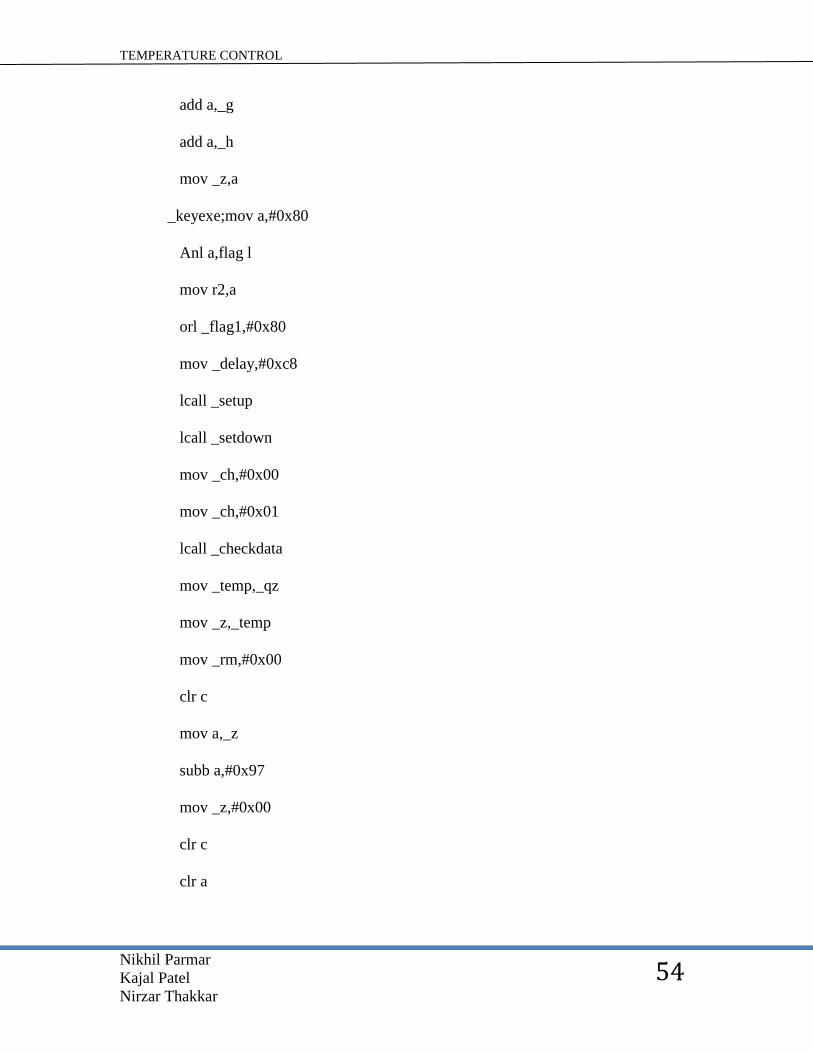
add a,_g
add a,_h
mov _z,a
_keyexe;mov a,#0x80
Anl a,flag l
mov r2,a
orl _flag1,#0x80
mov _delay,#0xc8
lcall _setup
lcall _setdown
mov _ch,#0x00
mov _ch,#0x01
lcall _checkdata
mov _temp,_qz
mov _z,_temp
mov _rm,#0x00
clr c
mov a,_z
subb a,#0x97
mov _z,#0x00
clr c
clr a
TEMPERATURE CONTROL
Nikhil Parmar
Kajal Patel
Nirzar Thakkar
55
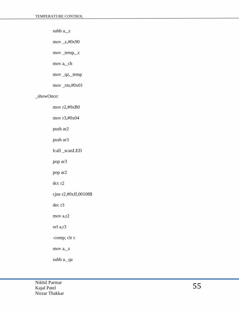
subb a,_z
mov _z,#0x90
mov _temp,_z
mov a,_ch
mov _qz,_temp
mov _rm,#0x01
_showOnce:
mov r2,#0xB0
mov r3,#0x04
push ar2
push ar3
lcall _scanLED
pop ar3
pop ar2
dcc r2
cjne r2,#0xff,00108$
dec r3
mov a,r2
orl a,r3
-comp; clr c
mov a,_z
subb a._qz

TEMPERATURE CONTROL
Nikhil Parmar
Kajal Patel
Nirzar Thakkar
56
mov _opto,#0xFF
mov _opto,#0xFF
_keydelay:
mov a,#0x80
anl a,_flag 1
mov r2,a
dec _delay
mov a,_delay
mov r2,_flag 1
mov a,#0x7F
anl a,r2
mov _flag 1,a
_pause: mov r2,dpl
mov r3,dph
mov r4,#0x00
mov r5,#0x00
clr c
mov a,r4
subb a,r2
mov a,r5
xrl a,#0x80
mov b,r3
TEMPERATURE CONTROL
Nikhil Parmar
Kajal Patel
Nirzar Thakkar
57
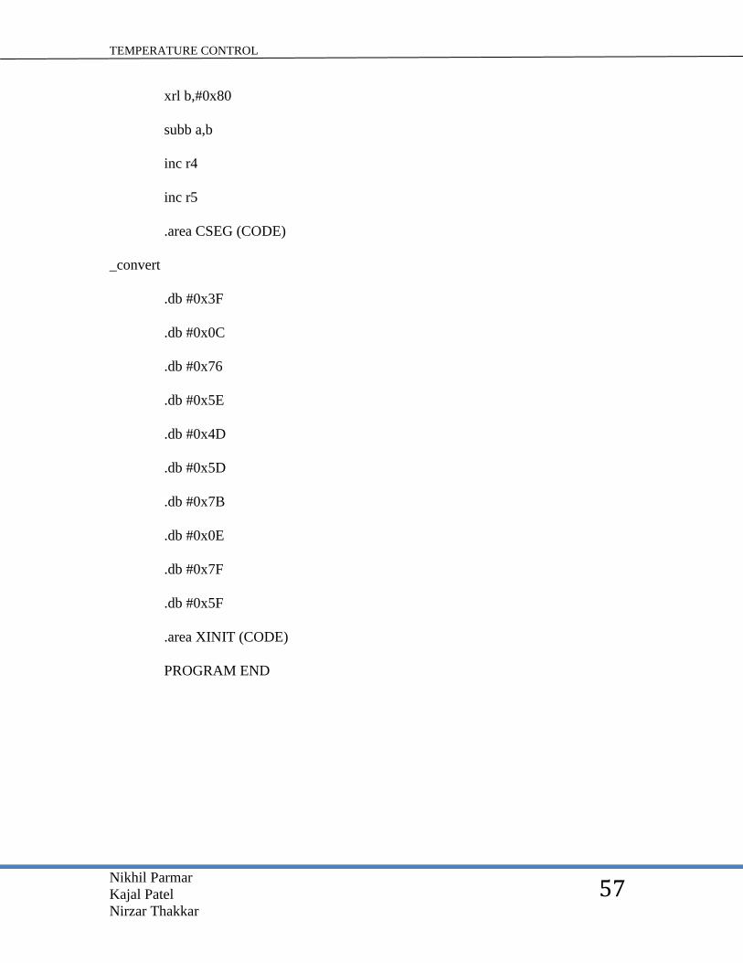
xrl b,#0x80
subb a,b
inc r4
inc r5
.area CSEG (CODE)
_convert
.db #0x3F
.db #0x0C
.db #0x76
.db #0x5E
.db #0x4D
.db #0x5D
.db #0x7B
.db #0x0E
.db #0x7F
.db #0x5F
.area XINIT (CODE)
PROGRAM END

TEMPERATURE CONTROL
Nikhil Parmar
Kajal Patel
Nirzar Thakkar
58
ADVANTAGES
Highly accurate due to the use of microcontroller.
Good sensing range due to the use of LM35Dz temperature sensor that is (0-
150)
Less bulky because the transformer used is of 12/500mA which is small in
size and less in weight.
External devices like air conditioners, fans, and heaters can be interface with
this device.
Digital output which in turns result in accurate threshold settings that results
into accurate driving of peripheral devices.
It displays the real tome temperature.
The device is small and easy to interface as well as easy to operate.

TEMPERATURE CONTROL
Nikhil Parmar
Kajal Patel
Nirzar Thakkar
59
DISADVANTAGES
The only disadvantage I have found in this project is that the temperature is available in
degree Celsius only. We have to manually convert it into Fahrenheit equivalent.
Though there is a option to write another microcontroller program to convert
temperature in degree Celsius to Fahrenheit but that is not viable for the project.
TEMPERATURE CONTROL
Nikhil Parmar
Kajal Patel
Nirzar Thakkar
60
APPLICATIONS
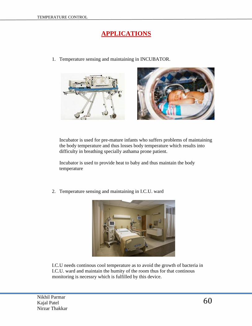
1. Temperature sensing and maintaining in INCUBATOR.
Incubator is used for pre-mature infants who suffers problems of maintaining
the body temperature and thus losses body temperature which results into
difficulty in breathing specially asthama prone patient.
Incubator is used to provide heat to baby and thus maintain the body
temperature
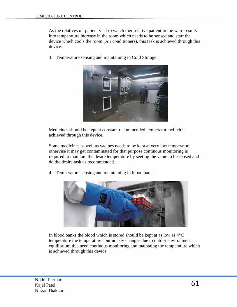
2. Temperature sensing and maintaining in I.C.U. ward
I.C.U needs continous cool temperature as to avoid the growth of bacteria in
I.C.U. ward and maintain the humity of the room thus for that continous
monitoring is necessry which is fulfilled by this device.
TEMPERATURE CONTROL
Nikhil Parmar
Kajal Patel
Nirzar Thakkar
61
As the relatives of patient visit to watch ther relative patient in the ward results
into temperature increase in the room which needs to be sensed and start the
device which cools the room (Air conditioners), this task is achieved through this
device.
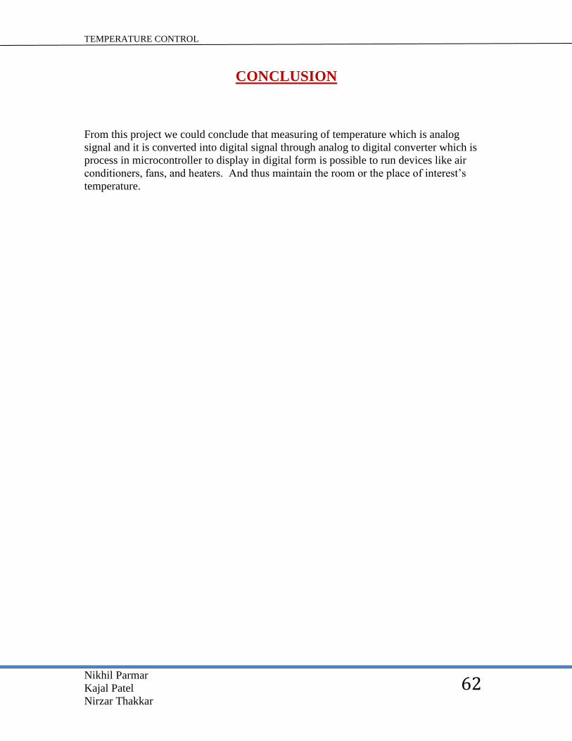
3. Temperature sensing and maintaining in Cold Storage.
Medicines should be kept at constant recommended temperature which is
achieved through this device.
Some medicines as well as vacines needs to be kept at very low temperature
othervise it may get contaminated for that purpose continous monitoring is
required to maintain the desire temperature by seeting the value to be sensed and
do the desire task as recommended.
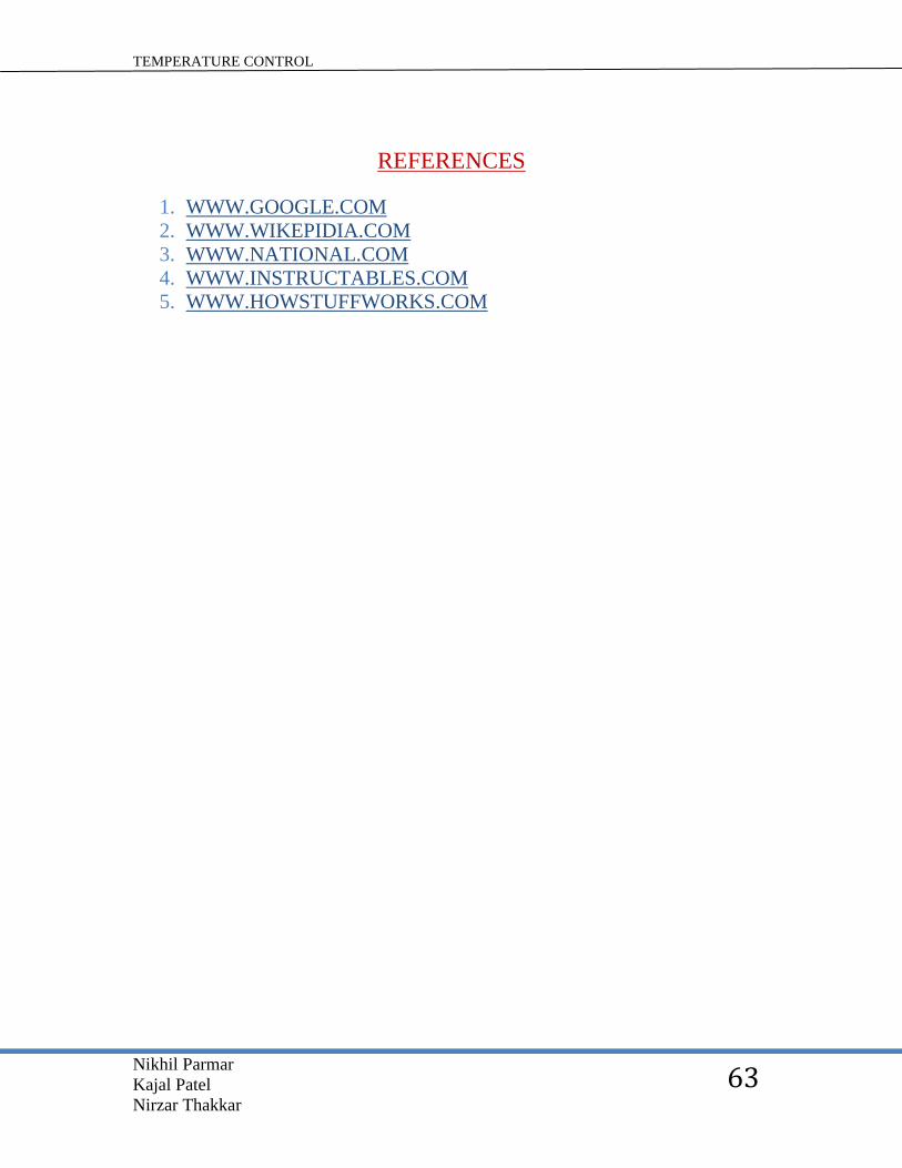
4. Temperature sensing and maintaining in blood bank.
In blood banks the blood which is stored should be kept at as low as 4°C
temperature the temperature continously changes due to outdor environment
equilibrium this need continous monitoring and maintaing the temperature which
is achieved through this device.
TEMPERATURE CONTROL
Nikhil Parmar
Kajal Patel
Nirzar Thakkar
62
CONCLUSION
From this project we could conclude that measuring of temperature which is analog
signal and it is converted into digital signal through analog to digital converter which is
process in microcontroller to display in digital form is possible to run devices like air
conditioners, fans, and heaters. And thus maintain the room or the place of interest’s
temperature.
TEMPERATURE CONTROL
Nikhil Parmar
Kajal Patel
Nirzar Thakkar
63
REFERENCES
1. WWW.GOOGLE.COM
2. WWW.WIKEPIDIA.COM
3. WWW.NATIONAL.COM
4. WWW.INSTRUCTABLES.COM
5. WWW.HOWSTUFFWORKS.COM