nio200iag user manualfiles.nexcom.com/driver/nio200/nio200_iag_user_manaul_v1...3.2.1 water proof...
TRANSCRIPT

November 2017 Page 1
NIO200IAG User Manual
V1.1
November 2017 Page 2
Content
Preface .......................................................................................................................................................... 4
1. General Information ......................................................................................................................... 9
1.1 Document Purpose ............................................................................................ 9
1.2 Definitions, Acronyms and Abbreviations ...................................................... 9
2 Product Overview ........................................................................................................................... 12
2.1 About the NIO200IAG Gateway .................................................................... 12
2.2 Logical Interfaces ............................................................................................. 12
2.3 Package Contents ............................................................................................ 13
3 Getting Started ................................................................................................................................ 14
3.1 Installation background ................................................................................... 14
3.2 Hardware installation Guide ........................................................................... 14
3.2.1 Water proof connector installation ......................................................... 15
3.2.2 Power installation ..................................................................................... 16
3.2.3 Antenna installation ................................................................................. 17
3.2.4 Earth grounding ........................................................................................ 18
3.2.5 Mounting of NIO200IAG.......................................................................... 18
3.3 Wi-Fi Mesh Network Configuration ............................................................... 21
3.3.1 Access to NIO200 Admin website ......................................................... 21
3.3.2 Configure the IP Address ........................................................................ 21
3.3.3 Change IPv4 address .............................................................................. 23
3.3.4 Enable NTP (Network Time Protocol) .................................................. 25
3.3.5 Select Time Zone ..................................................................................... 25
3.3.6 Select/Input Time Server ........................................................................ 26
3.3.7 Configure Wi-Fi Mesh Interface ............................................................. 27
3.3.8 Configure Physical Settings for Radio .................................................. 29
3.3.9 Network Settings of Wi-Fi Interface ...................................................... 30
3.4 ISA100 Gateway Configuration ..................................................................... 31
4 NIO200 Home page ......................................................................................................................... 32
5 Administration for the Network Devices .................................................................................. 33
5.1 Dashboard ......................................................................................................... 33
5.2 Topology ............................................................................................................ 35
5.3 Devices .............................................................................................................. 40

November 2017 Page 3
5.4 Device Details ................................................................................................... 44
5.5 Network Health ................................................................................................. 58
5.6 Readings ........................................................................................................... 59
5.7 Commands Log ................................................................................................ 60
5.8 Alerts .................................................................................................................. 63
5.9 Troubleshooting ................................................................................................ 65
5.10 Bulk Transfers .................................................................................................. 70
5.11 Set Country Code ............................................................................................ 71
6 Configuration ................................................................................................................................... 72
6.1 Backbone Router ............................................................................................. 72
6.2 Gateway ............................................................................................................ 75
6.3 System Manager .............................................................................................. 77
6.4 Device Management ........................................................................................ 80
6.4.1. Configuring Backbones ........................................................................... 81
6.4.2. Configuring Gateways ............................................................................. 83
6.4.3. Configuring Devices ................................................................................ 84
6.5 Monitoring Host ................................................................................................ 88
6.6 MODBUS ........................................................................................................... 89
6.7 Alert Subscription ............................................................................................. 90
6.8 Advanced Settings ........................................................................................... 90
6.8.1. Edit Configuration Variables ................................................................... 91
6.8.2. Restart ....................................................................................................... 92
6.8.3. Access NEXCOM NIO200 admin website ........................................... 93
6.9 Bulk Transfers .................................................................................................. 93
7. System Status .................................................................................................................................. 95
8. Administration ................................................................................................................................. 97
8.1 Device Firmwares ............................................................................................ 97
8.2 System Upgrade .............................................................................................. 99
8.3 Custom Icons .................................................................................................. 100
8.4 Custom Settings ............................................................................................. 100
8.5 Change Password .......................................................................................... 102

November 2017 Page 4
Preface
This manual is for user to set up a network environment using the NIO200 series Product line. It
contains step-by-step procedures and graphic examples to guide installer or individuals with slight
network system knowledge to complete the installation.
Copyright
This publication, including all photographs, illustrations and software, is protected under international
copyright laws, with all rights reserved. No part of this manual may be reproduced, copied, translated or
transmitted in any form or by any means without the prior written consent from NEXCOM International
Co., Ltd.
Disclaimer
The information in this document is subject to change without prior notice and does not represent
commitment from NEXCOM International Co., Ltd. However, users may update their knowledge of any
product in use by constantly checking its manual posted on our website: http://www.nexcom.com.
NEXCOM shall not be liable for direct, indirect, special, incidental, or consequential damages arising
out of the use of any product, nor for any infringements upon the rights of third parties, which may
result from such use. Any implied warranties of merchantability or fitness for any particular purpose is
also disclaimed.
Acknowledgements
NIO200 series are trademarks of NEXCOM International Co., Ltd. All other product names mentioned
herein are registered trademarks of their respective owners.
Safety Information
Before installing and using the device, note the following precautions:
▪▪ Read all instructions carefully.
▪▪ Do not place the unit on an unstable surface, cart, or stand.
▪▪ Follow all warnings and cautions in this manual.
▪▪ When replacing parts, ensure that your service technician uses parts specified by the manufacturer.
▪▪ Avoid using the system near water, in direct sunlight, or near a heating device.
Installation Recommendations
Ensure you have a stable, clean working environment. Dust and dirt can get into components and cause
November 2017 Page 5
a malfunction.
Use containers to keep small components separated.
Adequate lighting and proper tools can prevent you from accidentally damaging the internal
components. Most of the procedures that follow require only a few simple tools, including the
following:
▪▪ A Philips screwdriver
▪▪ A flat-tipped screwdriver
▪▪ A grounding strap
▪▪ An anti-static pad
Using your fingers can disconnect most of the connections. It is recommended that you do not use
needle-nose pliers to disconnect connections as these can damage the soft metal or plastic parts of the
connectors.
Safety Precautions
1. Read these safety instructions carefully.
2. Keep this User Manual for later reference.
3. Disconnect this equipment from any AC outlet before cleaning. Use a damp cloth. Do not use liquid
or spray detergents for cleaning.
4. For plug-in equipment, the power outlet socket must be located near the equipment and must be
easily accessible.
5. Keep this equipment away from humidity.
6. Put this equipment on a stable surface during installation. Dropping it or letting it fall may cause
damage.
7. The openings on the enclosure are for air convection to protect the equipment from overheating. DO
NOT COVER THE OPENINGS.
8. Make sure the voltage of the power source is correct before connecting the equipment to the power
outlet.
9. Place the power cord in a way so that people will not step on it. Do not place anything on top of the
power cord. Use a power cord that has been approved for use with the product and that it matches the
voltage and current marked on the product’s electrical range label. The voltage and current rating of the
cord must be greater than the voltage and current rating marked on the product.
10. All cautions and warnings on the equipment should be noted.
11. If the equipment is not used for a long time, disconnect it from the power source to avoid damage by
transient overvoltage.
12. Never pour any liquid into an opening. This may cause fire or electrical shock.
13. Never open the equipment. For safety reasons, the equipment should be opened only by qualified
service personnel.
14. If one of the following situations arises, get the equipment checked by service personnel:

November 2017 Page 6
a. The power cord or plug is damaged.
b. Liquid has penetrated into the equipment.
c. The equipment has been exposed to moisture.
d. The equipment does not work well, or you cannot get it to work according to the user’s manual.
e. The equipment has been dropped and damaged.
f. The equipment has obvious signs of breakage.
15. Do not place heavy objects on the equipment.
16. Be sure to ground the 0.75mm2 with an appropriate grounding wire (not included) by
attaching it to the grounding screw on the unit and to a good ground connection.
Earth, Green/Yellow wire, 18AWG, the minimum cross-sectional area of Earthing conductor
shall equal to Input wiring cable.
17. The front of the Equipment requires wiring terminals with the following specifications:
Wire size: 30-12 AWG (0.0509-3.3088 mm²)
Wire Type: copper wire only
Terminal Blocks Torque: 5 lb. In. (0.565 N-m).
For supply connections, use wires suitable for at least 75 degree C ambient
environment
- There must be a disconnect device in front of “NIO200 series” to keep the worker or
field side maintainer be cautious and aware to close the general power supply
before they start to do maintenance. The disconnect device hereby means a 20A
circuit-breaker. Power installation must be performed with qualified electrician and
followed with National Electrical Code, ANSI/NFPA 70 and Canadian Electrical Code,
Part I, CSA C22.1.
18.
(1) DC IN: 12-48Vdc, 2.1-0.6A
(2) LAN
(3) WAN(POE):57Vdc, 600mA
19. This equipment is intended to Ex nA IIC T4 Gc.
Note:
This equipment is intended to be mounted on a pole with the mounting bracket, wall mounting or DIN

November 2017 Page 7
mounting; the mounting should always let water proof connectors down to bottom position.
Cet équipement est destiné à être monté a la place avec le support de montage, montage mural ou
montage DIN; Le montage doit toujours laisser les connecteurs imperméable à la base.
This equipment is suitable for use in Class I, Division 2, Groups A, B, C, and D or non-hazardous
locations only.
Cet équipement est adapté à une utilisation en Classe I, Division 2, Groupes A, B, C et D ou des zones
non dangereuses uniquement.
- WARNING – EXPLOSION HAZARD. DO NOT CONNECT OR DISCONNECT WHEN
ENERGIZED.”
AVERTISSEMENT - RISQUE D'EXPLOSION. NE PAS CONNECTER NI DÉCONNECTER
LORSQU'IL EST EN CHARGE.
- Product is UL Listed with UL Listed Fittings for use with liquid-tight flexible metal conduit. This
wiring method is suitable for flexible connections in accordance with Article 501.10(B)(2) of the
National Electrical Code (ANSI/NFPA 70). Suitability for installation in particular applications is at
the discretion of the Authority Having Jurisdiction (AHJ) or similar.
- Le produit est homologué UL avec des accessoires homologués UL
pour conduit métallique flexible étanche aux liquids. ette méthode de câblage convient aux flexibles
connexions conformément à l'article 501.10 (B) (2) du National Code électrique (ANSI / NFPA
70). Pertinenced'installation dans certaines applications à la discrétion de l'Autoritéayant
Juridiction (AHJ) Ou similaire.
Technical Support and Assistance
1. For the most updated information of NEXCOM products, visit NEXCOM’s website at
www.nexcom.com.
2. For technical issues that require contacting our technical support team or sales representative, please
have the following information ready before calling:
– Product name and serial number
– Detailed information of the peripheral devices
– Detailed information of the installed software (operating system, version, application software, etc.)
– A complete description of the problem
– The exact wordings of the error messages
Warnings

November 2017 Page 8
Read and adhere to all warnings, cautions, and notices in this guide and the documentation supplied
with the chassis, power supply, and accessory modules. If the instructions for the chassis and power
supply are inconsistent with these instructions or the instructions for accessory modules, contact the
supplier to find out how you can ensure that your computer meets safety and regulatory requirements.
1. Handling the unit: carry the unit with both hands and handle it with care.
2. Opening the enclosure: disconnect power before working on the unit to prevent electrical shocks.
3. Maintenance: to keep the unit clean, use only approved cleaning products or cleans with a dry cloth.
Safety Warning: This equipment is intended for installation in a Restricted Access Location only
Avertissement de sécurité: Cet équipement est destiné à être installé uniquement dans
un lieu d'accès restreint
Cautions
Electrostatic discharge (ESD) can damage system components. Do the described procedures only at an
ESD workstation.
If no such station is available, you can provide some ESD protection by wearing an antistatic wrist strap
and attaching it to a metal part of the computer chassis.
Conventions Used in this Manual
Warning: Information about certain situations, which if not observed, can cause personal
injury. This will prevent injury to yourself when performing a task.
Caution: Information to avoid damaging components or losing data.
Note: Provides additional information to complete a task easily.

November 2017 Page 9
Note: The surface temperature of enclosure may exceed 70℃ under working
condition.
Remarque: La température de surface de l'enceinte peut dépasser 70 ℃ dans des
conditions de travail.
1. General Information
1.1 Document Purpose
This installation guide is designed to let user quickly get necessary installation
information about hardware as well as software so that the field installation can
be well done through this first aid.
1.2 Definitions, Acronyms and Abbreviations
The following table lists definitions, acronyms, and abbreviations that are only
suitable to this document.
Term Description
API Application Programming Interface
Backbone Any data network (e.g. industrial Ethernet, IEEE 802.11, etc.) within
a facility interfacing to the plants network.
Backbone Router An entity in the ISA100.11a network with routing capability which
serves as an interface between the radio network and the
backbone network.
BBR Backbone Router
Blacklisted channel A channel on which transmission is prohibited.
Broadcast Transmission intended for all the devices in an ISA100.11a network
(used for advertisements with all devices including the BBR, or for
receive links for field devices only).
CCA backoffs The count of transmissions on an RF channel that were aborted due
to CCA.

November 2017 Page 10
Term Description
CGI Common Gateway Interface
Channels Divisions of radio frequencies supported in a wireless network.
Contract An agreement between the system manager and a device in the
network involving the allocation of network resources by the
system manager to support a particular communication need of
that device.
Device role Device capabilities that will be accepted by the Security Manager.
DHCP Dynamic Host Configuration Protocol – a method to automatically
configure the IP settings of a host connected in a LAN.
EUI64, EUI-64 The 64-bit address of a device in the network; it is a unique
identifier usually set at the manufacturing of the device.
Field The geographic space that contains all the nodes of a wireless
network.
Field device A physical device designed to meet the rigors of plant operation
that communicates via DPDU’s conforming to the ISA100.11a
protocol.
Gateway An entity in the ISA100.11a network that serves as an interface
between the ISA100.11a network and a client.
Graph (communication) A collection of unidirectional interconnected devices, which defines
a set of communication paths between a source device and a
destination device.
Graph (Topology) A graphical representation of the network topology.
GW Gateway
Input/output A device with minimum characteristics required to participate in an
ISA100.11a network and which provides or uses data from other
devices.
ISA100.11a A communication protocol used in wireless networks, set up by the
Wireless Compliance Institute.
JSON JavaScript Object Notation
LAN Local Area Network
Link A momentary or persistent interconnecting path between two or
more devices for the purpose of transmitting and receiving
messaging.
MCS Monitoring Control System
Network Address The 128-bit address of a device in the network.

November 2017 Page 11
Term Description
Packet Error Rate The ratio, in percent, of the number of lost packets (DPDU’s) to the
total number of packets sent by the selected device to its parent.
Process value The quantity being controlled or the measurement value.
Provision To update settings on an entity in order to prepare it for working in
the network.
Revision The device software revision related to vendor/model.
Router A device that has data routing capability.
Security Manager An entity in the ISA100.11a network that assigns the security keys
that are required for communication between devices.
SM System Manager
Superframe A collection of timeslots with a common repetition period and
possibly other common attributes.
System Manager An entity in the ISA100.11a network that supervises the various
operational aspects of a network other than security.
TR Transceiver – the BBR radio
User Application
Process
From ISA100.11a standard: An active process within the highest
portion of the application layer that is the user of OSI (Open
Systems Interconnection) services.
UTC Coordinated Universal Time – A universal timekeeping standard
that is based on the Greenwich Mean Time (GMT). Local time is
calculated in UTC and offset by the local time zone.
FD Field Device
NIO210 NIO 200IAG – NEXCOM ISA100 Wireless All-in-One Gateway
November 2017 Page 12
2 Product Overview
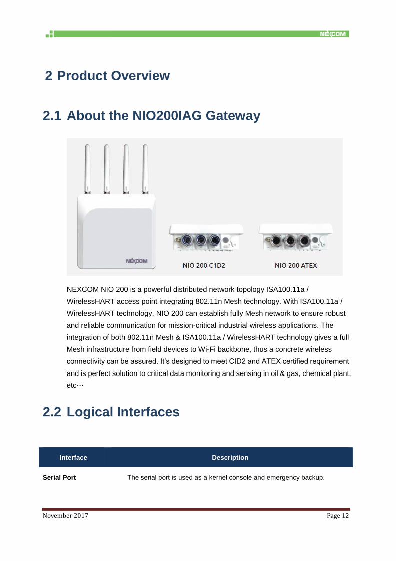
2.1 About the NIO200IAG Gateway
NEXCOM NIO 200 is a powerful distributed network topology ISA100.11a /
WirelessHART access point integrating 802.11n Mesh technology. With ISA100.11a /
WirelessHART technology, NIO 200 can establish fully Mesh network to ensure robust
and reliable communication for mission-critical industrial wireless applications. The
integration of both 802.11n Mesh & ISA100.11a / WirelessHART technology gives a full
Mesh infrastructure from field devices to Wi-Fi backbone, thus a concrete wireless
connectivity can be assured. It’s designed to meet CID2 and ATEX certified requirement
and is perfect solution to critical data monitoring and sensing in oil & gas, chemical plant,
etc…
2.2 Logical Interfaces
Interface Description
Serial Port The serial port is used as a kernel console and emergency backup.

November 2017 Page 13
Interface Description
TCP The NIO200IAG Gateway accepts the following TCP connections.
The NIO200IAG Gateway has an http server listening on port 80.
The NIO200IAG Gateway has an http server listening on port 8080.
The NIO200IAG Gateway has an https server listening on port 443.
The MODBUS TCP server is listening on TCP port 502.
The Standard GSAP interface is listening on TCP port 4900.
The GSAP over SSL is listening on TCP port 4901.
UDP The NIO200IAG Gateway utilizes the NTP protocol to synchronize time with
Internet time servers. The UDP port 123 must be open in both directions to allow
time synchronization.
NOTE: Not all interfaces are guaranteed to be up in all cases. Some might be disabled for specific
applications.
2.3 Package Contents
Each NIO200IAG gateway package contains the following items:
One NIO200IAG gateway
Two simple wall mounting kit
Three liquid-tight conduit (used only for DC power input and Ethernet port)
Two-pin DC power connector for 12~48 VDC power input
Grounding screws
Five outdoor antenna for evaluation purpose ( when deployed in field site, the antenna
should be changed so that the wireless capability can fit the application requirement )
One AC power adaptor with 12V output for evaluation purpose ( when deployed in field
site, DC power source may need to be changed )
One CID2 warning letter

November 2017 Page 14
3 Getting Started
3.1 Installation background
The web-based administration is the preferred method to administer/configure the NIO200IAG
Gateway. It requires a web browser and the IP of the NIO200IAG Gateway. The NIO200IAG Gateway is
suggested to connect to the local LAN then powered on, and the IP/mask or the router must be
accessible from the PC where the browser is running.
3.2 Hardware installation Guide
Hardware connection of NIO200 includes the power, Ethernet interfaces and RF
connectors. The installation of NIO200 should be carefully done with standard
waterproof connectors accessories in the package (CID2: conduit connector, ATEX:
cable gland connector).
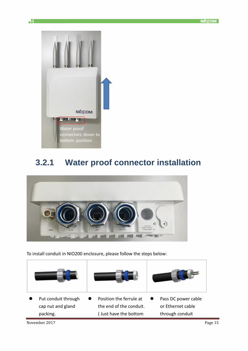
Note: the mounting of NIO200 should always let water proof connectors down to
bottom position. The following picture illustrates the proper mounting direction of
NIO200 in the field.
November 2017 Page 15
3.2.1 Water proof connector installation
To install conduit in NIO200 enclosure, please follow the steps below:
Put conduit through
cap nut and gland
packing.
Position the ferrule at
the end of the conduit.
( Just have the bottom
Pass DC power cable
or Ethernet cable
through conduit

November 2017 Page 16
of ferrule cover the
conduit, over-tighten
may enlarge conduit
diameter and loosen
Connect connector
into NIO200 enclosure,
tighten locknut with
body.
Insert the conduit with
ferrule into connector
of NIO200 enclosure.
Push gland packing and
cap nut forwards to
NIO200 conduit
connector and tighten
the cap nut
To install the conduit, user should implement with Flexible Metal Conduit, Liquid-tight which
meets UL360 standard. Here is the requirement of the diameter and size information for the
selection of Metal Conduit that mate with NIO200 conduit connectors.
3.2.2 Power installation
1. Prepare DC power source (12~48 VDC)
or standard PoE facility such PoE switch
or PoE injector.
2. If use external DC power source, please
carefully check if the polarity of power

November 2017 Page 17
cord fits the polarity drawing in this
diagram.
3. When use PoE power source, just plug
the Ethernet cable into PoE port.
4. If the power connects correctly, then the
“Power LED” will light accordingly.
3.2.3 Antenna installation
ISA100/WirelessHART antenna connector
Wi-Fi antenna connector for Wi-Fi Mesh
connection (WLAN 1 & WLAN 2)

November 2017 Page 18
3.2.4 Earth grounding
3.2.5 Mounting of NIO200IAG
Mounting method in NIO200IAG is default with simple wall mounting kit. If the
installation is with pole mounting method, then user should purchase pole mounting kit
for the installation. Here is the guide for both simple wall mounting method and pole
mounting method:
A.Simple wall mounting method:
1. Be sure to ground the 0.75mm2 ground screw
with an appropriate grounding wire ( Earth,
Green/Yellow wire 18AWG, not included) by
attaching it to a good earth ground connection.
2. There must be a disconnect device in front of
“NIO200 series” to keep the worker or field side
maintainer be cautious and aware to close the
general power supply before they start to do
maintenance.
3. The disconnect device hereby means a 20A
circuit-breaker. Power installation must be
performed with qualified electrician and followed
with National Electrical Code, ANSI/NFPA 70 and
Canadian Electrical Code, Part I, CSA C22.1.

November 2017 Page 19
1. Screw the simple wall mounting kit to the bottom of NIO200 enclosure.
2. Be sure to fasten the mounting kit with horizontal position as below:
3. Hang on NIO200 to the wall with water proof connector at the bottom direction. The
position of screw holes are 130mm width and height ( as specified in right picture
above )

November 2017 Page 20
B. Pole mounting method:
November 2017 Page 21
3.3 Wi-Fi Mesh Network Configuration
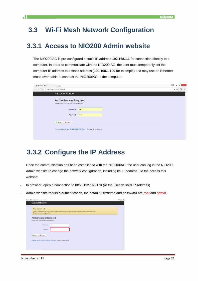
3.3.1 Access to NIO200 Admin website
The NIO200IAG is pre-configured a static IP address 192.168.1.1 for connection directly to a
computer. In order to communicate with the NIO200IAG, the user must temporarily set the
computer IP address to a static address (192.168.1.100 for example) and may use an Ethernet
cross-over cable to connect the NIO200IAG to the computer.
3.3.2 Configure the IP Address
Once the communication has been established with the NIO200IAG, the user can log in the NIO200
Admin website to change the network configuration, including its IP address. To the access this
website:
- In browser, open a connection to http://192.168.1.1/ (or the user defined IP Address)
- Admin website requires authentication, the default username and password are root and admin.

November 2017 Page 22
Click “Login” button without password and the following web page will appear:
Configure Network Interface
Select “Network -> Interface”
The following web page will appear.
The NIO200 is operated at Ethernet bridge mode:

November 2017 Page 23
Interface Name: LAN
Bridge Interface: br-lan
IP address: 192.168.1. 1
Physical Interfaces: eth1/eth2/wlan0/wlan1
3.3.3 Change IPv4 address
Click the “Edit” button belonging to “br-lan” network interface icon.
The following web page will appear.
As far as each interface is concerned, there are two configuration sections: “Common
Configuration” and “DHCP Server”.
Scroll down to the section “Common Configuration”, and click
November 2017 Page 24
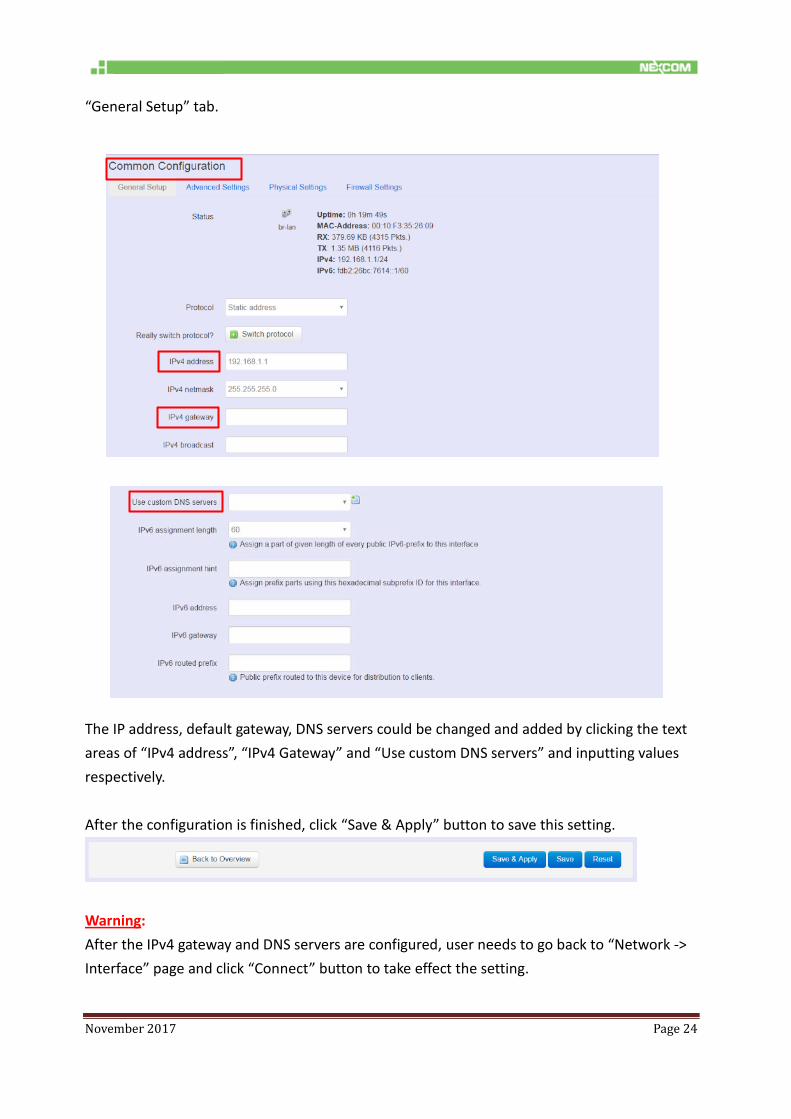
“General Setup” tab.
The IP address, default gateway, DNS servers could be changed and added by clicking the text
areas of “IPv4 address”, “IPv4 Gateway” and “Use custom DNS servers” and inputting values
respectively.
After the configuration is finished, click “Save & Apply” button to save this setting.
Warning:
After the IPv4 gateway and DNS servers are configured, user needs to go back to “Network ->
Interface” page and click “Connect” button to take effect the setting.

November 2017 Page 25
3.3.4 Enable NTP (Network Time Protocol)
Navigate to “System -> System”, and then the web page below will appear.
Click “General Settings” tab to configure “Local Time” and “Timezone” as shown below.
Configure NTP server in the “Time Synchronization” section when necessary.
Before NTP server is working, NIO200 should have correct date/time by clicking “Sync with
browser” and selecting “UTC” as Timezone.
3.3.5 Select Time Zone

November 2017 Page 26
3.3.6 Select/Input Time Server
NTP client is enabled by default.
Click “X” button to delete the incorrect or unwanted time server.
Keep clicking “X” buttons until only one item is left. Point the mouse cursor to text area and
input “time.nist.org”.
If new time server is required, click “+” button.

November 2017 Page 27
3.3.7 Configure Wi-Fi Mesh Interface
For Wi-Fi configuration and status reporting, navigate to “Network -> Wi-Fi” and click.
The following web page is shown, and contains two sections: “Wireless Overview” and
“Associated Stations”.
“Wireless Overview” section lists available Wi-Fi interfaces: wlan0 and wlan1.

November 2017 Page 28
“Associated Stations” section lists run-time connection information for each Wi-Fi interface
(mesh mode).
Take wlan0/radio0 interface for example.
Edit:
For editing the configuration profile of Wi-Fi interface, click this button
There are 2 configuration sections in the web page: “Device Configuration” and “Interface
Configuration”.
The parameters in the “Device Configuration” are related to physical settings of Wi-Fi radio.
The parameters in the “Interface Configuration” are related to network settings of Wi-Fi
interface, which is built upon the Wi-Fi radio.
Scan: For displaying the list of all access points around with the same frequency band as this
radio has, click this button.

November 2017 Page 29
3.3.8 Configure Physical Settings for Radio
The physical settings (radio parameters of Wi-Fi interface) exists in this “Device Configuration”
section.
Clicking “General Setup” tab.
There are 4 basic types of physical settings required for radio: 802.11 protocol, 5GHz Channel,
Bandwidth, and Transmit Power.
There are 2 options for “802.11 protocol”: N (802.11n) and Legacy (802.11a).
There are 10 options for channel selection in 5GHz band.
802.11 protocol 5GHz channel Bandwidth

November 2017 Page 30
Width: There are 4 options for bandwidth selection. 2 options (“20MHz” and “40MHz”) are
used for AP or STA client mode. 2 options (“40 plus” and “40 minus”) are used for mesh mode
Transmit Power: There are 14 options.
3.3.9 Network Settings of Wi-Fi Interface
The network settings (network parameters of Wi-Fi interface) exists in this “Interface
Configuration” section.
Clicking “General Setup” tab
ESSID/Mesh ID: (Default: “MESH_CAN2”) Network name.
All products with the same ID (or network name) and radio physical settings (802.11 protocol and
channel) are connected together automatically.
Mode: (Default: “Mesh, 802.11s”) Wireless network topology. Only mesh is supported.

November 2017 Page 31
3.4 ISA100 Gateway Configuration
ISA100 gateway specific network management and configuration takes place into the Monitoring
Control System (MCS). Steps to access the MCS:
Step Action
1. Open the following URL: http://192.168.1.1:8080/ (or, replacing <NIO200IAG_IP> with NIO
200IAG Gateway IP if the IP address was changed from default setting.).
Once the address is accessed, the login screen appears, as shown in below.
2. Type the following user name and password in the Login fields:
Username: the username provided. ( Default: admin )
Password: use the password provided. ( Default: adminadmin )
3. Click the Login button to access ISA100 gateway configuration

November 2017 Page 32
4 NIO200 Home page
Once the credentials are entered and access is granted, the browser will display the Device List
by default.
Figure 1
The user interface consists of two sections:
The menus on the left, which allow you to navigate through the pages of the website
The main section, which displays the contents of the selected page
November 2017 Page 33
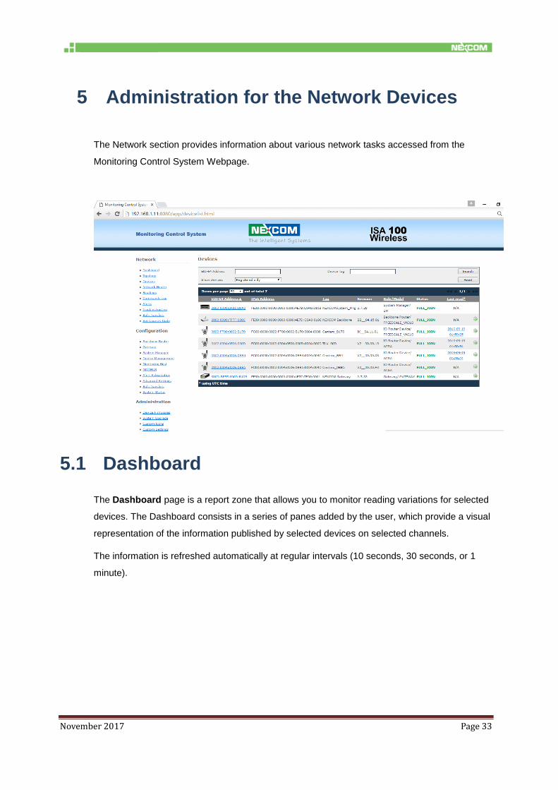
5 Administration for the Network Devices
The Network section provides information about various network tasks accessed from the
Monitoring Control System Webpage.
5.1 Dashboard
The Dashboard page is a report zone that allows you to monitor reading variations for selected
devices. The Dashboard consists in a series of panes added by the user, which provide a visual
representation of the information published by selected devices on selected channels.
The information is refreshed automatically at regular intervals (10 seconds, 30 seconds, or 1
minute).

November 2017 Page 34
To delete a device from the dashboard, click in the top right corner of the pane. No
confirmation is required for the system to delete the pane.
To add a device to the dashboard, perform the following steps:
Step Action
1. Click on the Add Device button.
2. The Device dialog box will open:
Select a Device from the drop-down list.

November 2017 Page 35
Step Action
3. Select the Channel that you wish to monitor from the drop-down list.
4. Type the desired gauge value range for the readings; if the selected values are out of
range, a message on the pane will notify you.
5. Optional, select the Slot number (up to the current slot number); if you do not select a
slot number, the system automatically assigns the next available slot.
6. Select the desired Gauge type.
7. Click OK to add the device to the dashboard.
NOTE:
You can also add a reading to the dashboard from the Device Details page: in the
Information pane, click the Add to dashboard (ATD) icon next to a reading.
Up to 9 devices are supported in the dashboard.
5.2 Topology
The Topology page displays a graphical representation of the current network topology as well
as allows users to view data about contracts and devices.

November 2017 Page 36
The system performs regular automatic updates of the topology information. When you load the
page, the topology graph is generated based on the latest topology information available. The
time of the last topology information update is indicated at the top of the page. To view the latest
topology, press Refresh – this will generate a Request Topology command and will refresh the
page.
In the SubnetID drop-down list located at the top of the topology window, select a subnet to
view.
The registered devices are displayed on multiple levels represented as grey bands. The levels
are numbered from 0 to n. The level number is indicated in the upper left corner of a level. The
Gateway, the System Manager, and the Backbone Router are found on level 0. The level is
given by the preferred clock source. A device is on level one, if its preferred clock source is a
backbone router. A device is on level 2 if its preferred clock source is on level 1 and so on.
Communication-wise, field devices are linked to the backbone router, which is the central device
in the network, either directly or via other devices. The backbone router further relays to the
Gateway, while the System Manager organizes the entire network. The field devices can have
various sensors attached: temperature sensors, humidity sensors, etc.
The devices are identified in the topology by the last four characters of their EUI-64 address. For
easier identification, the backbone router, the gateway and the system manager are identified
with the abbreviations BBR, GW, and SM. The devices are placed within a level in the order of
their EUI64 address. They can be moved freely within the range of their level by drag-and-drop
to obtain better legibility of the topology.
In addition, they are represented by suggestive icons and against backgrounds of different colors,
to distinguish their roles (also shown in the Devices legend at the bottom of the page):
Gateway – purple background
Backbone Router – blue
System Manager – dark green
IO/Router Devices – blue
IO Devices – light green
Routers - red
By positioning the cursor over an icon, you can view the tooltip, which includes the following
details for a device:
EUI-64 address
device role
November 2017 Page 37
subnet ID
device tag
manufacturer
model
The available Topology page elements and viewing options are described in the following
paragraphs.
Adjusting Width and Height
You can adjust the size of the topology representation using the buttons and for height
and width.
You can also adjust the height and width to the size of the Topology pane by clicking , or
revert to the original viewing settings by clicking .
Links
When the page is loaded, the Links option located above the topology graph is selected by
default. The backbone router is also selected by default in the topology graph and the Preferred
ClockSource links to it are displayed as green lines.
To view the Preferred ClockSource for a particular device, click on the device in the topology
graph, or select the device in the drop-down list located on top of the Topology window. The
MCS will display the device’s link to its preferred ClockSource.
To view the Secondary ClockSource links for a selected device, check this option in the Links
Legend. These links are displayed in blue in the topology graph.
To view the transmission links between a selected device and other, check the Links option in
the Links Legend. The regular links are displayed in black in the topology graph.
To view all the other links formed between the network devices, check the Show all links option.
This option is unchecked by default.
To view the RSQI signal value for a device’s links, check the Show signal quality/PER option.
The signal quality value is displayed next to each link and is colored in the color of the respective
link.
To view the packet error rate for a device:
First check the Show signal quality/PER option
In the Links Legend, select the desired ClockSource links to display (Preferred or
Secondary, or both)
November 2017 Page 38
Click the Get PER for selected device button located in the Links Legend. The PER is
shown as a percentage next to the respective link
Contracts
To view the contracts for a selected device:
Step Action
1. Check the Contracts option located at the top of the topology graph.
2. Choose a device by clicking on it in the topology graph or by selecting it in the Devices
drop-down list located above the graph.
3. In the Contracts drop-down list you will view the selected device’s inbound and
outbound contracts with the System Manager and the Gateway. To show a contract on
the graph, select it in the list.
The contract will be represented by a green line if it is periodic or by a blue line if it is
aperiodic.
The Contracts legend located at the bottom of the Topology page also indicates how
the types of contracts and links are represented.
NOTE: A device can have both a periodic and an aperiodic contract with the same SM or GW at
the same time.

November 2017 Page 39
Contract details
In addition, when you select a contract, information about the contract parameters will be shown
in the Contract details section at the bottom of the page.
The contract information includes the following parameters:
Contract ID – the contract identifier based on the contract owner
Service type – can be periodic or aperiodic
Source/destination device – the EUI64 address of the requester, and the destination
device respectively
Source / destination SAP –“0” is the default value for the DMAP on a device; “1” is the
default value of a SMAP on the System Manager; the other values represent custom
SAP’s
Activation time – the date and time when the contract was established
Expiration time – the date and time when the contract terminates
Priority – indicates the base priority for all messages sent using the contract
NSDU Size – the packet size at network layer
Reliability – the requested reliability for delivering the transmitted packets to the
destination
Period – identifies the desired publishing period, for periodic contracts

November 2017 Page 40
Phase – identifies the desired phase (within the publishing period) of publications, for
periodic contracts
Deadline – the maximum end-to-end transport delay desired, in periodic communication
Committed Burst – for long-term aperiodic communication; it specifies the bandwidth:
A positive value specifies the packets transmitted per second; e.g. a committed
burst of 2 indicates that two packets per second are guaranteed
A negative value specifies the number of seconds per packet; e.g. a committed
burst of -15 indicates that a packet transmitted every 15 seconds is guaranteed
Excess Burst – for short-term aperiodic communication; it has the same significance as
the committed burst, but is only used in exceptional situations where aggressive
communication is needed on a short-term
MaxSendWindow – the maximum number of client requests that may be simultaneously
awaiting a response, in the case of aperiodic communication
5.3 Devices
The devices page features the list of devices that exist in the network and a search form that
enables you to search devices based on their EUI-64 address, tag and/or state.
Search devices

November 2017 Page 41
When the device page is loaded, the registered devices are displayed by default.
Step Action
Search by EUI-64 address
1. To search a device by its EUI-64 address, type the address in the EUI-64 Address
input field,
or
For a partial search:
Type part of the EUI-64 address in the EUI-64 Address input field
Select the desired state from the Show Devices drop-down list
2. Click Search. The system will retrieve all the devices whose EUI-64 addresses contain
the characters provided by the user.
NOTE: To delete the search parameters, click Reset.
Search by device tag
1. A tag is a custom description that you can assign to a device in order to facilitate
identification of that device in the plant. One tag can be assigned to a single device.
To search for devices based on their tag, type the tag in the Device Tag input field.
2. Click Search.
NOTE: The tag field is case sensitive.
To delete the search parameters, click Reset.
Search by device state only
1. To display devices based on their state at a given time, select the desired state from the
Show Devices drop-down list. The device list will update automatically.
A device can be in only one of the following states at a given moment in time:
Registered – the device has successfully joined the network and is ready to
operate
Joining process – the device has been provisioned and is attempting to join the
November 2017 Page 42
Step Action
network
Unregistered – the device has lost connection with its neighbors in the network
Device List
The Device list shows the network devices in a table, one item per line, with main information
about each logical device:
EUI-64 address (the MAC address),
IPv6 address
Tag – the device tag
Revision – the firmware version available on the device
Role (Gateway, System Manager, Backbone Router, Field Router) and model
(manufacturer information)
Status (“Full Join” for registered devices; “Joining” for joining devices; “Not Joined” for
unregistered devices), and
Last Read (the date and time of the last reading from the device) and a link to the
Readings page for the device in question.
In addition, the device list provides a quick link to the Run Commands page for that specific
device.
When you load the page, the registered devices are displayed by default. To view unregistered
or joining devices, select the corresponding option in the Show Devices drop-down list.
The total number of items in the table is indicated in the top left corner of the table. Here you can
set the number of items to be displayed per page in the table. The default number of items
displayed in a page is 10. Paging controls in the top right corner of the table also enable you to
navigate through the other pages of the table.
The last time the page was refreshed is also indicated at the top of the page. The page does not
refresh automatically; therefore you must click Refresh to update it.
Delete a device
In the devices page you have the option of deleting an unregistered device. When you delete a
device, it will be removed from the network and any related data, including previous readings,
will be deleted from the database.

November 2017 Page 43
To delete the device, click the icon located next to the device. The system will require
confirmation to perform the action. Click OK to delete the device or Cancel to abort the action.
November 2017 Page 44
5.4 Device Details
In this page you can see all the information available for the selected device and perform
device-specific commands. The page is accessed by clicking on the device EUI-64 address in
the device list.
The page is organized into seven tabbed panes by types of information and also features a Back
button to allow you to quickly revert to the Devices page, as well as an indication of when the last
page was updated and a Refresh button (where applicable) that enables you to retrieve
up-to-date information in the specific page.
Information
The Information pane displays general as well as activity specific information about the device.
When the page is loaded, it shows the latest information available. To update the information,
click Refresh.
The following details are shown in addition to those already indicated in the device list:
Manufacturer – the name of the device manufacturer
Revision – the radio firmware version
Subnet ID – the ID of the subnet that includes the device
Power Supply Status – represented as a battery with the following colors:
green, when the device is line powered
blue, when the device is battery powered, and the remaining capacity of the
battery is greater than 75%
yellow, when the device is battery powered, and the remaining capacity of the
battery is between 25% and 75%
red, when the device is battery powered, and the remaining capacity of the
battery is less than 25%
Data transmission statistics – the number of transmitted/received packages and the
number of failed transmissions/receptions
Process values – the parameters measured by the device.

November 2017 Page 45
Process values
The process values are displayed in a table with the following related information:
Name - the process value name
M.U. - the unit of measurement for the process value
Format - various formats are possible, defining the value range of the measured
parameter: int8, uint8, int16, uint16, int32, uint32, float32
TSAP ID
Object ID
Attribute ID, and
Two indices.
The total number of items in the table is indicated in the top left corner of the table. Here you can
set the number of items to be displayed per page in the table. The default number of items
displayed in a page is 10. Paging controls in the top right corner of the table also enable you to
navigate through the other pages of the table.
Settings
The settings reflect the current operation of the ISA100.11a stack on a device.
The type of information displayed in this pane includes neighbor details, routes and graphs:

November 2017 Page 46
Neighbors
The Neighbors section lists the registered neighbors of the selected device as well as indicates
their signal quality and whether they are clock sources for the selected device.
A clock source neighbor can have one of the following roles:
Preferred clock source – the reference clock source for the selected device.
Secondary clock source – a backup clock source that becomes preferred, when the
reference clock source is not available.
Multiple neighbors may be designated as clock sources for a selected device.
The Signal Quality column displays the received signal quality indicator (RSQI) values and their
associated labels, as shown in the following table:
RSQI Signal Quality
1-63 Poor signal
64-127 Fair signal
128-191 Good signal
192-255 Excellent signal
Graphs
The Graphs section lists all the graphs that include the selected device, with the specific graph
ID’s and neighbor addresses within each graph.
Graph 1 is the inbound graph, while the other graphs are outbound graphs.

November 2017 Page 47
Routes
The Routes section lists the routes of which the source is the selected device.
Routes can be classified into:
Routes based on graphs, established between two field devices or a field device and the
Backbone Router
Hybrid routes – established between the Backbone Router and a joined device (the
destination of the route) for which an outbound graph has not been created yet. Hybrid
routes consist of the node’s parent’s outbound graph and the destination node.
Routes are listed in a table displaying the following information:
Route ID – route identification data; ID’s are given in the order of creation of the routes.
Route 1 is the default route established between field devices and the Backbone Router.
Alternative – a number ranging from 0 to 3 that enables you to differentiate between
routes based on their source and destination:
If the alternative is 0, the route is based on a contract requested by the System
Manager or the Gateway. This feature will be available in future releases.
If the alternative is 1, the route is established between two field devices
If the alternative is 2, the Backbone Router is the source of the route and a field
device is the destination.
If the alternative is 3, this is the device’s default route (Route 1) to the Backbone
Router.
Selector – identifies the destination of the route; the selector varies based on the value
of the alternative:
If the alternative is 0, the selector indicates the contract ID and the address of
the source (SM or GW)
If the alternative is 1, the selector field indicates the contract ID.
If the alternative is 2, the selector field indicates the address of the destination
device.
If the alternative is 3, the selector is null.
Forward Limit – the maximum number of nodes that a route can include
Route Element – indicates the ID of the graph that stands at the basis of the route, or the
graph ID and the destination’s address, for hybrid routes.

November 2017 Page 48
To view the updated device settings, click the Refresh button. The Request Topology and Get
Contracts and Routes commands will be sent to the System Manager.
When the command is generated, a message at the bottom of the screen will indicate that the
device information is refreshing.
Registration Log
The registration log displays the registration history for the selected device, at different dates and
times, commonly known as timestamps.
Use the Search functionality to view the behavior of the device over a specific period time:
Choose the status you wish to view from the Registration Status drop-down list
Optional, fill in the Start Time and the End Time fields, and then click Search.
The results are displayed in a table that indicates the timestamp and the device status at that
specific timestamp. A device can have one of the following statuses at a given moment:
SEC_JOIN_Req – the security join request was received by the System Manager
SEC_JOIN_Rsp – a security join response was sent to the device
NETWORK_Req – the network join request was received by the SM
NETWORK_Rsp – the network join response was sent to the device
CONTRACT_Req – the join contract request was received by the SM
CONTRACT_Rsp – the join contract response was sent to the device
SEC_CNFRM_Req – the security join confirmation was received by the SM
SEC_CNFRM_Rsp – the security join confirmation response was sent to the device

November 2017 Page 49
FULL_JOIN – the device is joined and configured and all information about it is available
NOT_JOINED – the device is not joined
The total number of items in the table is indicated in the top left corner of the table. Here you can
set the number of items to be displayed per page in the table. The default number of items
displayed in a page is 10. Paging controls in the top right corner of the table also enable you to
navigate through the other pages of the table.
Neighbors Health
This pane provides a communication health report about the selected device’s neighbors.
The report includes:
Neighbor identification information - the EUI-64 address
The timestamp of the report request
A general link status:
Available – if the neighbor is available for communication
Unavailable – if the neighbor is unavailable for communication
Communication health information:
The number of DPDU's transmitted to the neighbor and the number of failed
transmission attempts
the number of DPDU’s received from the neighbor and the number of failed
receptions from the neighbor
The neighbor signal strength (measured in dBm) and
The signal quality (for the RSQI ranges and associated labels

November 2017 Page 50
The total number of items in the table is indicated in the top left corner of the table. Here you can
set the number of items to be displayed per page in the table. The default number of items
displayed in a page is 10. Paging controls in the top right corner of the table also enable you to
navigate through the other pages of the table.
Schedule Report
The schedule report pane provides information about time slot and channel allocation for the
selected device.
Superframes and links
The active Superframes that the device uses for communication are listed in the page along with
information regarding size (the number of time slots), start time, and the number of links
allocated on each Superframe.
Clicking on the number of links will display a new page with link related information for each
individual link allocated on the selected Superframe, as shown in the following screen:

November 2017 Page 51
The following details are shown:
Neighbor – the EUI-64 address of the neighbor or the broadcast address
FFFF:FFFF:FFFF:FFFF (used only for advertisements and receive links)
Slot index – the ID of the slot within the Superframe
Link period – the periodicity of a link (measured in No. of slots) within a Superframe
cycle
Slot length – expressed as a multiple of 2-20 seconds
Channel number
Direction – reception or transmission
Link type, which can be:
aperiodic data communication
aperiodic management communication
periodic data communication
periodic management communication
You can use the search form on the top of the page to sort links based on neighbor device, the
link type of the direction of the communication.

November 2017 Page 52
In addition, in both the Superframes and Links tables you can sort the information by the number
of items listed per page. The default number of records displayed in a page is 10. Paging
controls at the bottom of the table enable you to navigate through the pages of the table.
When the pages are loaded, the latest information available is shown. To update the information,
click Refresh.
RF Channels
The channels of the device are represented at the bottom of the pane. The channels that are
clear for communication are highlighted in blue, the unused channels are highlighted in gray,
while blacklisted channels are highlighted in red.
Channel 26 has been disabled by default for purposes of compliance in certain countries.
Channel Statistics
This pane displays statistical information about CCA backoffs per channel.
The information is presented in a table, with the value column expressing the percentage (0% to
100%) of aborted transmissions for each channel.
To update the information, click Refresh.
Run Commands

November 2017 Page 53
This pane enables you to perform device-specific commands.
To go to a specific command, select it from the Commands drop-down list. After you generate
the command, a message at the bottom of the screen will indicate its status (“Command sent
successfully”, “Command sent error”). The tracking number of the command is also indicated,
together with a link to the Commands Log, where you can view the results of the command.

November 2017 Page 54
The following types of commands are available:
Read Value
This command is available only for field devices and enables you to read a value on a particular
channel of the selected device.
To generate the command, select the process value for which to request a reading and click
Execute. The returned value will be displayed in the Readings page, in engineering units under
the Value column as well as in the Command Log, under the Response column.
NOTE: When the device is unregistered, the Run Commands tab is unavailable.
Reset Device
This command resets the firmware on the specific device.
Three types of resets can be performed on a device:
Warm Restart – performs a software reset; as a consequence, the device will unregister
and re-register
Restart as provisioned – resets the device while keeping provisioning information
Reset to factory defaults – deletes the provisioning information and resets the device to
its manufacturing settings; the device must be re-provisioned in order to be able to join
the network

November 2017 Page 55
This command is available for all network devices with two exceptions:
The command cannot be performed on the System Manager
The Reset to factory defaults option is not available on the gateway
Read Object Attribute
Using this command you can read attributes from an object on the selected device.
To read an attribute, type in the UAP specific TSAP ID (port), the Object ID, and the Attribute
ID you wish to read. Then click Execute.
NOTE: The values of the two indices are 0 by default and the value of the Committed Burst field is
-15 by default.
The command returns the content of the attribute, which will be displayed in hex format in the
Response column of the Commands Log page.

November 2017 Page 56
Write Object Attribute
This command enables you to write/edit a value to an object on the selected device. Only certain
attributes are editable.
To write the attribute, type in the TSAP ID (port), the associated Object ID, and the Attribute ID
you wish to write or edit. Then type the desired hex value(s) in the Values input field. And click
Execute.
NOTE: The values of the two indices are 0 by default and the value of the Committed Burst field is
-15 by default.

November 2017 Page 57
Execute Object Attribute
The execute service is used to execute a network visible method on an object on the selected
device.
To execute the method, type in the TSAP ID, the associated Object ID, and the Method ID you
wish to execute. Provide the method details in hex format in the Details input field. Click
Execute.
NOTE: The values of the two indices are 0 by default and the value of the Committed Burst field is
-15 by default.

November 2017 Page 58
5.5 Network Health
The Network Health page provides a communication health report at network level.
The page consists of two sections containing network summary statistics and device-specific
communication health information.
In the network summary section the following information is indicated:
Network ID and Network Type - network identification data(where applicable)
Devices Count – the total number of registered devices, including the Backbone Router
Join count – the total number of joins of all the devices in the network
Current Date – the present time
Start Date – the date and time the System Manager application was started
Transmission and reliability statistics, based on the summary report per device
The averaging interval for GPDU statistics, reported in seconds
The device communication report section consists of a table displaying the following information
for each device:
EUI-64 Address – the network address of the device
Start Date – the date and time of the device’s first join

November 2017 Page 59
DPDU’s Sent – the total number of packets sent by the device
DPDU’s Lost – the total number of packets sent by the device which failed to reach
destination
GPDU Latency – the percentage of scheduled GPDU's that arrive later than expected
GPDU Path Reliability – the percentage of GPDU’s transmitted successfully on a
primary path
GPDU Data Reliability – the percentage of successful GPDU’s (transmit GPDU’s that
are transferred correctly on the first attempt plus receive GPDU’s that pass integrity
checks)
Join Count – the total number of joins per device
The total number of items in the table is indicated in the top left corner of the table. Here you can
set the number of items to be displayed per page in the table. The default number of items
displayed in a page is 10. Paging controls in the top right corner of the table also enable you to
navigate through the other pages of the table.
The last time the page was refreshed is also indicated in the page. To update the information,
click Refresh.
5.6 Readings
In this page you can view the readings received from devices, which are generated either on
demand by Read Value commands or by automatic Publish/Subscribe commands. The readings
can be filtered by Device, Process Value, or Reading Type (Publish/Subscribe or On
Demand).

November 2017 Page 60
To search for readings, select the desired device, process value and reading type as shown in
the screen above, and click Search. The results are displayed in a table that contains the
following information for each reading:
Device EUI-64 address (MAC address of the device that reported the reading)
Timestamp (date and time of the reading)
Channel Name (the process value name)
Value (the value received on that particular reading) – shown in engineering values
Unit of Measurement (if applicable)
Reading Type
The total number of items in the table is indicated in the top left corner of the table. Here you can
set the number of items to be displayed per page in the table. The default number of items
displayed in a page is 10. Paging controls in the top right corner of the table also enable you to
navigate through the other pages of the table.
From this page you can also save the search results into a Microsoft Excel CSV file, by clicking
Export.
5.7 Commands Log
In this page you can view all the commands issued on the registered devices in the system. The
commands can be filtered by Device, Command (type), or Command Status (New – command

November 2017 Page 61
posted in database, Sent – command sent to device, Responded – device responded
successfully to the command, Failed – command failed to execute).
To search for commands, select the desired device, command and command status and click
Search. The results will be displayed in a table, as shown in the screen above, with the following
information for each command:
Tracking Number (internal ID of the command),
EUI-64 address (MAC address of the command destination device),
Command (name of the executed command)
Parameters (description of the parameters chosen for the command, if applicable)
Status (current status of the command)
Posted Time (date and time when the command was generated)
Response Time (date and time when the command was responded successfully or not)
Response (the response for the issued command if the command was responded
successfully or the error reason if the command failed), which can consist of:
The measured value expressed in engineering units for the Read Value
command
The hex value for Read/Execute Object Attribute commands
The mention success for all the other types of commands executed on devices

November 2017 Page 62
If the length of the response exceeds the size of the Response cell, click on the response link to
open the Tracking Response form and view the full response:
Given the large number of commands generated automatically by the system at regular intervals,
these commands are hidden by default. To view them, check the Show system generated
commands option in the Search dialog and click Search.
The total number of items in the table is indicated in the top left corner of the table. Here you can
set the number of items to be displayed per page in the table. The default number of items
displayed in a page is 10. Paging controls in the top right corner of the table also enable you to
navigate through the other pages of the table.
From this page you can also save the search results into a Microsoft Excel CSV file, by clicking
Export.

November 2017 Page 63
5.8 Alerts
The Alerts page enables you to view alarms and events generated by devices.
Alerts consist in application messages that advise or warn the recipient of the presence of an
impending or existing situation of interest.
Two types (classes) of alerts are supported in accordance with the ISA100.11a specification:
Events – indicates that something happened with the device
Alarms – indicates that a device has transitioned to an abnormal state, or has returned
to normal from an abnormal state. An alert is sent to describe the change of state
To search for alerts:
Select the device, the alert category, priority and class of alert
Optional, fill in the Start Time and the End Time fields, and then click Search
The results are displayed in a table that indicates the following information:
EUI-64 address – the MAC address of the device generating the alert
TsapID and ObjectID – identification of the application process and the associated
object that initiated the alert
Time – the date and time when the alert condition was detected

November 2017 Page 64
Class – the type of alert (alarm or event)
Direction – with the following values:
Start/End – only for alarms, it indicates if the report is for an alarm condition, or a
return to normal from an alarm condition
N/A – if the alert reports an event
Category – device diagnostic, communication-related, security-related, or process
related
Priority – indicates the importance of the alert, with the following ranges and associated
labels, in compliance with the specification:
0 - 2: Journal-only
3 - 5: Low
6 - 8: Medium
9 - 11: High
12 -15: Urgent
Value – indicates the value associated with the alert condition.
You can set the number of records to be displayed per page in the table. The default number of
records displayed in a page is 10. Paging controls at the bottom of the table allow you to
navigate through different pages of the search results.
From this page you can also save the search results into a Microsoft Excel CSV file, by clicking
Export.
November 2017 Page 65
5.9 Troubleshooting
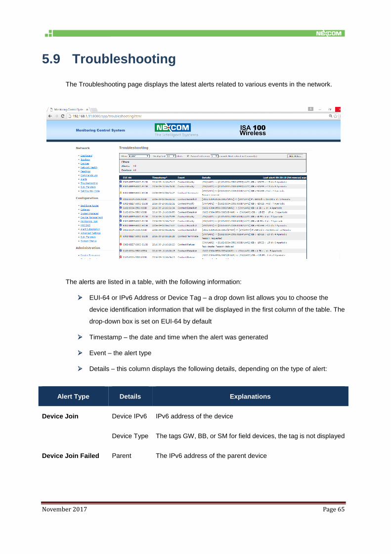
The Troubleshooting page displays the latest alerts related to various events in the network.
The alerts are listed in a table, with the following information:
EUI-64 or IPv6 Address or Device Tag – a drop down list allows you to choose the
device identification information that will be displayed in the first column of the table. The
drop-down box is set on EUI-64 by default
Timestamp – the date and time when the alert was generated
Event – the alert type
Details – this column displays the following details, depending on the type of alert:
Alert Type Details Explanations
Device Join Device IPv6 IPv6 address of the device
Device Type The tags GW, BB, or SM for field devices, the tag is not displayed
Device Join Failed Parent The IPv6 address of the parent device

November 2017 Page 66
Phase
Join Phase Join Phase Description
4 SECURITY_JOIN_Req
5 SECURITY_JOIN_Rsp
6 NETWORK_JOIN_Req
7 NETWORK_JOIN_Rsp
8 JOIN_CONTRACT_Req
9 JOIN_CONTRACT_Rsp
10 SECURITY_CONFIRM_Req
11 SECURITY_CONFIRM_Rsp
Reason The reason number and description
Device Leave Reason The reason number and description
The time elapsed from the last alert
NOTE: Contract Alerts and Topology Alerts will be implemented in a future version of the MCS.
The Display last N alerts drop-down list allows you to select the maximum number of alerts to
display in the table. You can choose a value between 50, 100, 150, and 200.
To always view the latest alerts, enable the Autorefresh every N seconds checkbox. You can
choose a value between 5, 10, 15, 30, and 60 seconds.
Filters
The Edit filters button allows you to define the filters to apply for displaying the alerts. Click the
button to expand the upper section of the page:

November 2017 Page 67
Under Devices, select the devices for which you want to display alerts. Checking/unchecking the
All checkbox in the table header will check/uncheck all the devices.
Under Alert Class & Types, you will view a hierarchy of application alerts and you can select the
desired alerts combination.
Checking/unchecking an alert class will check/uncheck all the alert types in that class.
Checking/unchecking the All checkbox in the table header will check/uncheck all the alerts.
Pressing Clear Filter will reset the filters to All for both the Devices list and the Alerts list.
Each alert is preceded by an icon indicating the severity of the alert:
- Information
- Warning
- Error
The Severity Icon is displayed for each Alert in the Troubleshooting table based on the following
mapping:
Alert Reason Severity
Device join/leave alerts

November 2017 Page 68
Alert Reason Severity
Device Join info
Device Join Failed 1: Timeout (device does not
respond to SM queries)
warning
2: Re-join (new join request while
joining)
warning
3: Parent left the network during
device join
warning
8: Insufficient parent resources -
will retry join trough another
router
warning
4: Device removed from SM
whitelist
error
5: Device not found SM whitelist error
6: Invalid join key - mismatch with
key from SM whitelist
error
7: Invalid challenge - already
used in a Security_Join_Request
(possible retry)
error
9: SubnetID mismatch (device
provisioning/SM whitelist
mismatch)
Error
Device Leave 1: Timeout - device does not
respond to SM queries
error
2: Re-join (new join request while
joined)
error
3: Parent left the network error

November 2017 Page 69
Alert Reason Severity
4: Device removed from SM
whitelist
error
Contract Alerts
Contract Establish info
Contract Modify info
Contract Refusal 1: Insufficient resources error
2: Delayed (try again later) error
3: Device not found error
4: Contract not found (it applies
to modification/renewal)
error
5: Invalid request (requested an
operation that cannot be
performed or the request
contains invalid parameters)
error
6: timeout (no response to
contract request). This reason
can only be set by the FD.
Error
Contract Terminate 1: requested info
2: expired
3: unjoin
Topology alerts
Parent Change info
Backup Change info
November 2017 Page 70
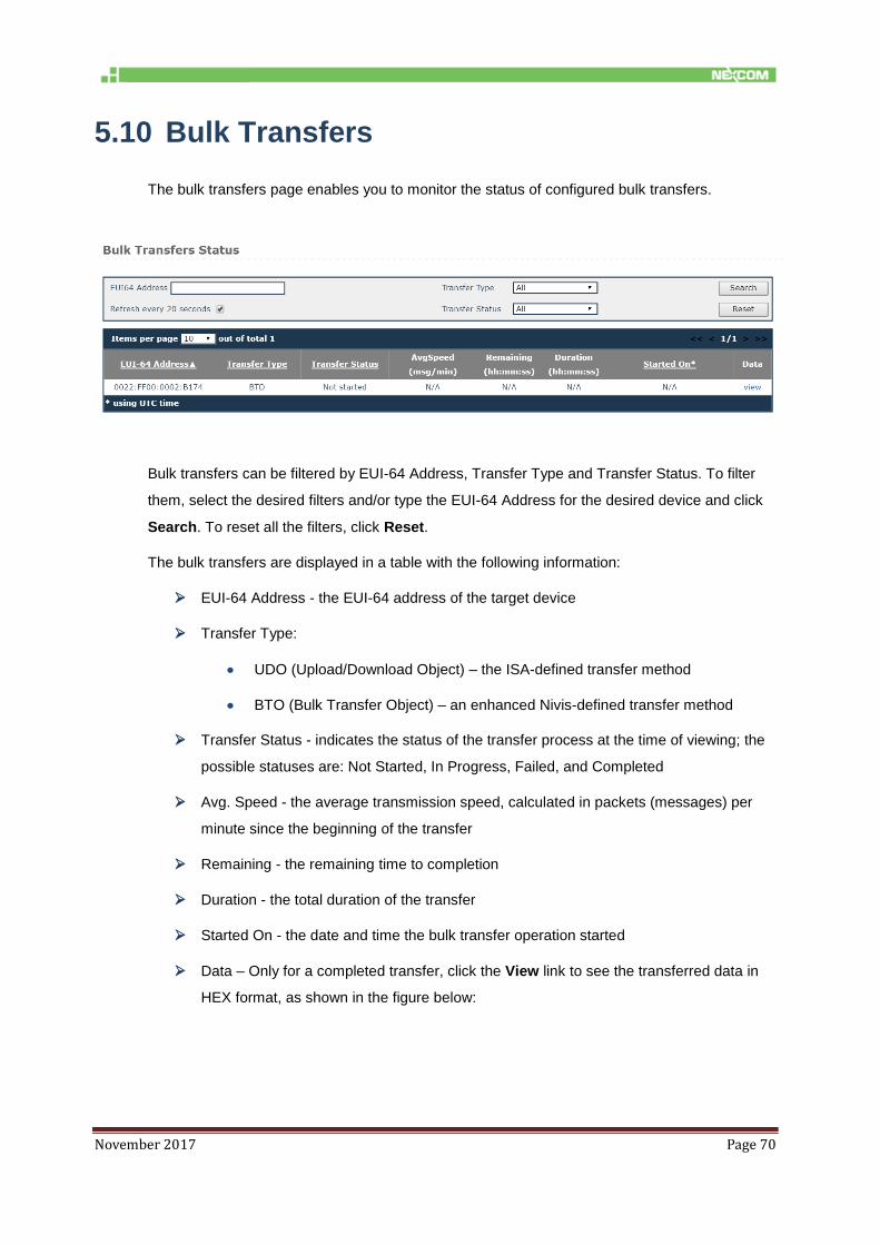
5.10 Bulk Transfers
The bulk transfers page enables you to monitor the status of configured bulk transfers.
Bulk transfers can be filtered by EUI-64 Address, Transfer Type and Transfer Status. To filter
them, select the desired filters and/or type the EUI-64 Address for the desired device and click
Search. To reset all the filters, click Reset.
The bulk transfers are displayed in a table with the following information:
EUI-64 Address - the EUI-64 address of the target device
Transfer Type:
UDO (Upload/Download Object) – the ISA-defined transfer method
BTO (Bulk Transfer Object) – an enhanced Nivis-defined transfer method
Transfer Status - indicates the status of the transfer process at the time of viewing; the
possible statuses are: Not Started, In Progress, Failed, and Completed
Avg. Speed - the average transmission speed, calculated in packets (messages) per
minute since the beginning of the transfer
Remaining - the remaining time to completion
Duration - the total duration of the transfer
Started On - the date and time the bulk transfer operation started
Data – Only for a completed transfer, click the View link to see the transferred data in
HEX format, as shown in the figure below:

November 2017 Page 71
To refresh the information in the table regularly, check the Refresh every 20 seconds option in
the Search form.
The total number of items in the table is indicated in the top left corner of the table. Here you can
set the number of items to be displayed per page in the table. The default number of items
displayed in a page is 10. Paging controls in the top right corner of the table also enable you to
navigate through the other pages of the table.
5.11 Set Country Code
The page allows setting the Country Code on the field devices and on the transceiver, to follow
country-specific RF regulations.
Choose the country in the “Country Code” drop down, select the devices to configure, click
Execute.

November 2017 Page 72
6 Configuration
The configuration section enables you to view and edit certain settings for the
configuration/provisioning of the devices and the network, including connection settings,
publishers, alert subscriptions, and Modbus register mapping.
IMPORTANT:
This section is intended for users with thorough technical knowledge, and certain
configurations require advanced expertise, therefore they should be carefully planned,
as any inconsistencies may render the devices/network inoperative.
NOTE: The changes you perform in the settings for each separate entity will also be reflected in the
Advanced Settings page and vice-versa.
6.1 Backbone Router
The Backbone Router configuration page consists of 5 sections, as shown is the table below.
Step Action
General Settings
1. Specify the EUI64 and the BBR Tag.
NOTE:
Hover over an edit box and a tooltip will appear, indicating the
allowed format and range for each value.
If you change any of these settings, you must restart the
Backbone Router in order for the new settings to take effect.

November 2017 Page 73
Step Action
Provision/security
2. Specify the Subnet ID – which must be the same for all the devices in a subnet, the
Subnet Mask, and Specify the APP Join Key.
NOTE:
Hover over an edit box and a tooltip will appear, indicating the
allowed format and range for each value.
If you change any of these settings, you must restart the
Backbone Router in order for the new settings to take effect.
Take care: the subnet ID is hexadecimal in this page (while it is
decimal in the Device management page, as well as in the
Gateway Configuration page)

November 2017 Page 74
Step Action
Logging
3. Select the Stack Logging level. The numbers suggest the degree of detail provided in
the Backbone Router logs:
1 (ERROR) for error messages only
2 (WARN) for error and warning messages
3 (DEBUG) for error, warning and debug messages
Time Settings
4. Select NTP servers if the NIO 200IAG Gateway has access to internet
In case the NIO 200IAG does not have access to the internet, time synchronization can
be performed by using the transceiver clock as the time source
5. When you have finished editing the settings, click Save. As mentioned above,
depending on the settings that you modify, the backbone router may need to be
restarted for the changes to take effect.

November 2017 Page 75
6.2 Gateway
The Gateway configuration page consists of 3 sections, as shown is the table below.
Step Action
General Settings
1. Specify the EUI64, IPv6 Address, UDP Port Number, and the GW Tag.
NOTE:
Hover over an edit box and a tooltip will appear, indicating the
allowed format and range for each value.
If you change any of these settings, you must restart the gateway
in order for the new settings to take effect.
Provision/security
2. Specify the Subnet ID and the APP Join Key.
NOTE:
Hover over an edit box and a tooltip will appear, indicating the
allowed format and range for each value.
If you change any of these settings, you must restart the gateway
in order for the new settings to take effect.

November 2017 Page 76
Step Action
Logging
3. Select the App Logging level and the Stack Logging level. The numbers suggest the
degree of detail provided in the Backbone Router logs:
1 (ERROR) for error messages only
2 (WARN) for error and warning messages
3 (DEBUG) for error, warning and debug messages
4. When you have finished editing the settings, click Save. As mentioned above,
depending on the settings that you modify, the backbone router may need to be
restarted for the changes to take effect.

November 2017 Page 77
6.3 System Manager
The System Manager configuration page consists of 3 sections, as shown is the table below.
Step Action
General Settings
1. Specify the EUI64.
NOTE:
Hover over an edit box and a tooltip will appear, indicating the
allowed format and range for each value.
If you change any of these settings, you must restart the system
manager in order for the new settings to take effect.

November 2017 Page 78
Step Action
Operational Settings
2. Fill in the input fields with the desired/appropriate values.
Enable the desired frequency channels for communication with the network devices.
NOTE:
Hover over an edit box and a tooltip will appear, indicating the allowed
format, range and a description (where necessary for disambiguation) for
each value.

November 2017 Page 79
Step Action
Logging
3. Select the Logging level, which indicates the degree of detail provided in the logs:
ERROR for error messages only
WARN for error and warning messages
INFO for error, warning, and information messages
DEBUG for error, warning, information, and debug messages
4. When you have finished editing the settings, click Save.
5. Select the Logging level, which indicates the degree of detail provided in the
logs:
ERROR for error messages only
WARN for error and warning messages
INFO for error, warning, and information messages
DEBUG for error, warning, information, and debug messages
6. When you have finished editing the settings, click Save.

November 2017 Page 80
6.4 Device Management
This section enables you to edit the provisioning information (the SM whitelist) in the
“system_manager.ini” file for existing devices and to add new devices to the network.
IMPORTANT:
WARNING! Do not change these settings unless you were specifically instructed by a
NEXCOM representative! Incorrect values may render the devices dysfunctional, or may
cause difficulty to trace malfunctions.
NOTE: This page is not exposed into the left-hand menu. The user must type its URL in order to access it.
To access the page, Open the following URL: http://<NIO200IAG_IP>/admin/devicemng.html
replacing <NIO200IAG_IP> with NIO 200IAG Gateway IP. Provide any credentials may be
requested if the user is not already logged in
Click Help in the upper right corner of the window to view information and examples of the
accepted data formats in all the sections.
NOTE:
The EUI-64 address is unique in a network.
All the devices in a subnet must have the same security key and the same Subnet
ID.

November 2017 Page 81
The number of backbone routers in a network equals the number of subnets in that
network.
6.4.1. Configuring Backbones
Step Action
To add a backbone router in the network
1. Type the EUI64, security key, and subnet ID in the empty edit box.
2. Click the Save button.
3. The new backbone router will be added to the Backbones list.
4. Click the Activate button to load the changes into the System Manager. The changes
will be visible in the network topology and where applicable in the device list.
To edit a backbone router
1. Click on the entry that you want to edit in the backbones list.
2. Edit the security key and/or subnet ID, and click Save to save the changes in the
“system_manager.ini” file.
NOTE:
If you try to edit the EUI64 address of an existing backbone
router, the SM will recognize it as a new entity and will add the
new backbone router to the list.
If you edit a BBR, it will be removed from an existing subnet and
the devices in that subnet will be unable to join the network,
unless you edit the same parameters for all the field devices in
that subnet.
Take care: the subnet ID is decimal in this page (while it is
hexadecimal in the BBR Configuration page)
3. Click the Activate button to load the changes into the System Manager. The
changes will be visible in the network topology and where applicable in the
device list.
To delete a backbone router

November 2017 Page 82
Step Action
1. Select the desired backbone router in the list and click Delete.
2. You will be asked for confirmation. Click Yes to delete the backbone router or No to
abort the action.
NOTE:
When you delete a backbone router the devices in its subnet will be
unable to join until a new backbone router provisioned with the same
security key and subnet ID is added to that subnet.
3. Click the Activate button to load the changes into the System Manager. The
changes will be visible in the network topology and where applicable in the
device list.

November 2017 Page 83
6.4.2. Configuring Gateways
NOTE: By design the NIO 200IAG Gateway supports only one ISA100 Gateway; therefore it is not
permitted to add more than one gateway to the system.
Step Action
To edit the gateway
1. Click on the entry that you want to edit in the gateways list.
2. Edit the security key and/or subnet ID, and click Save to save the changes in
the“system_manager.ini” file.
3. Click the Activate button to load the changes into the System Manager. The changes
will be visible in the network topology and where applicable in the device list.
To delete the gateway
1. Select the desired gateway in the list and click Delete.
2. You will be asked for confirmation. Click Yes to delete the gateway or No to abort the
action.
IMPORTANT:
Caution! If you delete the gateway, you will no longer be able to
access the system and retrieve any data, although the network
remains functional.
4. Click the Activate button to load the changes into the System Manager. The
changes will be visible in the network topology and where applicable in the
device list.

November 2017 Page 84
6.4.3. Configuring Devices
Adding devices:
You can add devices either individually, one device at a time, or you can add multiple
devices at a time.
To add a single device in the network, type it’s EUI64, security key, and
subnet ID in the empty edit box and click Save. The new device will be
added to the Devices list.
To add multiple devices with consecutive EUI-64 addresses type the
range of EUI-64 addresses corresponding to the devices that you wish to
add; subsequently, type the security key, and the subnet ID and click
Save.
The follow example shows how a series of devices with consecutive EUI-64 address
can be added to a subnet.
Example:
“6302:0304:0506:0B1A - 6302:0304:0506:0B1E,C0 C1 C2 C3 C4 C5 C6 C7 C8 C9 CA CB CC CD CE
CF,17, 3”
NOTE:
When you add a device or a range of devices into the network you can define their role,
which is expressed as an integer value and is added after the subnet ID in the device
format.
The following table details the role values and associated labels:
Integer Value Role
1 IO Device
2 Router Device
3 IO Routing Device

November 2017 Page 85
The following aspects must be taken into consideration when defining the role for a device or
range of devices:
1. Upon join, each device states its capacity.
2. The roles of the backbone router and the gateway cannot be changed, therefore providing a
role value in this section is unnecessary.
3. The role selection for a field device is limited to the capacity stated by that device.
Examples:
If a device has only the IO role, you cannot add the Routing role for that device
in the Device Management section.
If a device has both the IO and the Routing roles, you can limit its role in the
network to one of the two, by typing either 1 or 2 after the subnet ID.
If you do not specify a role in this section, the System Manager will admit the
role(s) stated by the device.
4. If you add the role for a range of devices, all the devices in question will have the same
role. If any device in the range does not support the assigned role, the device will not join
the network.
Step Action
To edit a device/multiple devices
1. In the device list, click on the entry that you want to edit.
2. Edit the security key and/or subnet ID.
NOTE: See the previous Note on Device Roles if you wish to edit device roles.
3. Click Save to save the changes in the“system_manager.ini” file.
4. Click the Activate button to load the changes into the System Manager. The changes
will be visible in the network topology and where applicable in the device list.
To delete a device/multiple devices
1. Select the desired entry in the list and click Delete.
November 2017 Page 86
Step Action
2. You will be asked for confirmation. Click Yes to delete the device(s) or No to abort the
action.
3. Click the Activate button to load the changes into the System Manager. The changes
will be visible in the network topology and where applicable in the device list.

November 2017 Page 87
Loading a List of Devices
You can add multiple devices at the same time by importing them from a file. The file will contain
a list of devices with the <EUI64>, <Key>, and <subnet>) comma separated values.
Step Action
To load a list
1. Click on Browse to locate the text file that you wish to load, and click Upload.
2. Click the Activate button to load the new device list into the System Manager. The
current “system_manager.ini” file will be overwritten and all previous settings will be
lost.
Exporting the settings
1. This page also enables to export the configuration settings, by clicking Save in the
“Manage device list” section.

November 2017 Page 88
6.5 Monitoring Host
This section enables you to configure the devices publishing settings stored in the
“Monitor_Host_Publishers.conf” file. The settings are used by the Monitor Host to subscribe to
the data published by the field devices.
NOTE:
The settings in this page do not get sent to the field devices. Field devices
must be separately provisioned with publish settings (channels to publish,
period, phase, endpoint, etc.)
Click Help in the upper right corner of the window to view information and examples of the
accepted data formats in all the sections.

November 2017 Page 89
The publishers’ configuration can be performed manually, by user adding/editing the lines in
the page, or automatically, by interrogating automatically the field devices. The automatic
publisher discovery is recommended method.
If the automatic publishers’ discovery is enabled: Auto Activate ON means the changes take
effect immediately as a device respond to MH interrogations. If Auto Activate is OFF the
changes will not take effect until the user press the Activate button, or until the software gets
restarted
6.6 MODBUS
This section enables you to map ISA100.11a attributes to Modbus registers.
Click Help in the upper right corner of the window to view information and examples of the
accepted data formats in all the sections.

November 2017 Page 90
6.7 Alert Subscription
This page enables you to subscribe to alerts generated in the system.
To subscribe to an alert category, enable the checkbox preceding it and click Save. When an
alert to which you subscribed is generated, it will be listed in the Alerts page.
6.8 Advanced Settings

November 2017 Page 91
6.8.1. Edit Configuration Variables
This page allows you to view/set less common configuration variables, which cannot be changed
using the classic MCS web interface.
IMPORTANT:
This page is for advanced users only – do not use unless you have been instructed exactly
by a NEXCOM representative on what values to change. Incorrect values may render the
router dysfunctional, or may cause difficulty to trace malfunctions.
Step Action
1. The following form will open to the right of the operation list:
2. In the form, select a Section in the drop-down list. The Variable list will change
accordingly.
3. Select a Variable in the drop-down list.
IMPORTANT: Do not change [GLOBAL].AN_ID under any circumstance.
4. Set/edit the Value field, then click Set.

November 2017 Page 92
5. To add a new variable, select Custom under Variable type. The Sections/variables form
will be empty.
6. Type the desired information in the Section, Variable, and Value fields, then click Set.
6.8.2. Restart
This section enables the user to restart the applications running on the NIO 200IAG Gateway.
The “Apply all settings” button apply all settings (re-load into all modules the configuration files)
The “Restart Applications” restart all applications, without rebooting the board.
The “Stop Applications” stops all applications, for powering the board off after an ordered shut
down.
The “Restart NIO200” reboots the NIO 200IAG Gateway.
NOTE:
After restarting the applications or rebooting the NIO 200IAG Gateway, the Monitoring
Control System becomes inoperative for a few minutes.
After Stopping the applications, the Monitoring Control System becomes inoperative until
the next power cycle.

November 2017 Page 93
6.8.3. Access NEXCOM NIO200 admin website
This section allows the user to navigate to NEXCOM NIO200 admin website, where the NIO200
Network Configuration (Wi-Fi settings, IP Addresses, NTP Server, etc.) can be changed.
6.9 Bulk Transfers
The Bulk Transfers page enables you to create and configure bulk transfers. Bulk data transfers
are used to transfer large items between wireless devices (sensor boards) and gateway clients.
This can be done via two methods:
A transfer method described by ISA running on top of UDO
A Nivis enhanced bulk data transfer protocol
Already configured bulk transfers are displayed in a table, with the following information:
EUI-64 Address – the EUI-64 Address of the source device
Transfer Type – the selected transfer protocol (UDO or BTO)

November 2017 Page 94
TsapID –
Device Tag – the device tag for the source device
Status – the status of the transfer
The total number of items in the table is indicated in the top left corner of the table. Here you can
set the number of items to be displayed per page in the table. The default number of items
displayed in a page is 10. Paging controls in the top right corner of the table also enable you to
navigate through the other pages of the table.
You can also delete a bulk transfer, by clicking the icon next to it. The system will require
confirmation to perform the action. Click Yes to delete the bulk transfer or Cancel to abort the
action.
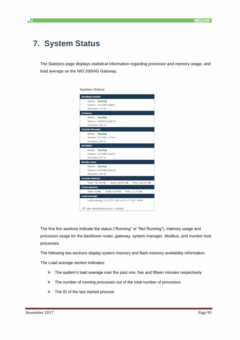
November 2017 Page 95
7. System Status
The Statistics page displays statistical information regarding processor and memory usage, and
load average on the NIO 200IAG Gateway.
The first five sections indicate the status (“Running” or “Not Running”), memory usage and
processor usage for the backbone router, gateway, system manager, Modbus, and monitor host
processes.
The following two sections display system memory and flash memory availability information.
The Load average section indicates:
The system’s load average over the past one, five and fifteen minutes respectively
The number of running processes out of the total number of processes
The ID of the last started process

November 2017 Page 96
If you wish to regularly update the system status information, enable the Auto refresh page
option at the bottom of the page. The page will auto refresh at one-minute intervals.
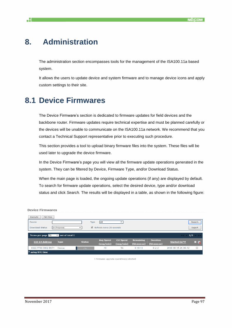
November 2017 Page 97
8. Administration
The administration section encompasses tools for the management of the ISA100.11a based
system.
It allows the users to update device and system firmware and to manage device icons and apply
custom settings to their site.
8.1 Device Firmwares
The Device Firmware’s section is dedicated to firmware updates for field devices and the
backbone router. Firmware updates require technical expertise and must be planned carefully or
the devices will be unable to communicate on the ISA100.11a network. We recommend that you
contact a Technical Support representative prior to executing such procedure.
This section provides a tool to upload binary firmware files into the system. These files will be
used later to upgrade the device firmware.
In the Device Firmware’s page you will view all the firmware update operations generated in the
system. They can be filtered by Device, Firmware Type, and/or Download Status.
When the main page is loaded, the ongoing update operations (if any) are displayed by default.
To search for firmware update operations, select the desired device, type and/or download
status and click Search. The results will be displayed in a table, as shown in the following figure:
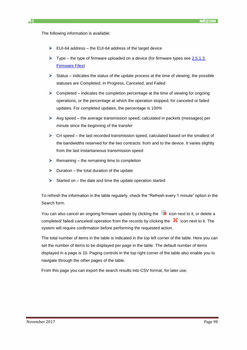
November 2017 Page 98
The following information is available:
EUI-64 address – the EUI-64 address of the target device
Type – the type of firmware uploaded on a device (for firmware types see 2.5.1.3
Firmware Files)
Status – indicates the status of the update process at the time of viewing; the possible
statuses are Completed, In Progress, Canceled, and Failed
Completed – indicates the completion percentage at the time of viewing for ongoing
operations, or the percentage at which the operation stopped, for canceled or failed
updates. For completed updates, the percentage is 100%
Avg speed – the average transmission speed, calculated in packets (messages) per
minute since the beginning of the transfer
Crt speed – the last recorded transmission speed, calculated based on the smallest of
the bandwidths reserved for the two contracts: from and to the device. It varies slightly
from the last instantaneous transmission speed
Remaining – the remaining time to completion
Duration – the total duration of the update
Started on – the date and time the update operation started
To refresh the information in the table regularly, check the “Refresh every 1 minute” option in the
Search form.
You can also cancel an ongoing firmware update by clicking the icon next to it, or delete a
completed/ failed/ canceled/ operation from the records by clicking the icon next to it. The
system will require confirmation before performing the requested action.
The total number of items in the table is indicated in the top left corner of the table. Here you can
set the number of items to be displayed per page in the table. The default number of items
displayed in a page is 10. Paging controls in the top right corner of the table also enable you to
navigate through the other pages of the table.
From this page you can export the search results into CSV format, for later use.

November 2017 Page 99
8.2 System Upgrade
The System Upgrade page enables you to upgrade the system components hosted on the
connected NIO 200IAG Gateway.
The Firmware form indicates the current system version on the NIO 200IAG Gateway.
To initiate the upgrade
Step Action
1. Click Browse to locate and open the upgrade package that you wish to use:
2. Click the Upload Firmware button to initiate the process.
3. Make sure the NIO200 has a reliable power source. When asked click OK

November 2017 Page 100
Step Action
4. When the upgrade is complete, the page indicates the result of the upgrade:
8.3 Custom Icons
This page enables you to assign custom icons for the devices in a network based on their role,
with a view to better distinguishing them.
When the page is loaded, the existing custom icons are displayed in a table, with the following
information:
Model – the device model
Role – the device role
Icon – shows the existing picture
The default icons are not listed.
8.4 Custom Settings
This page enables user to define whether the timestamps get shown using browser local time
zone or UTC; apply color themes to the website; replace the NEXCOM logo with a logo of
preference in the website header, and enable/disable various high-side interfaces.
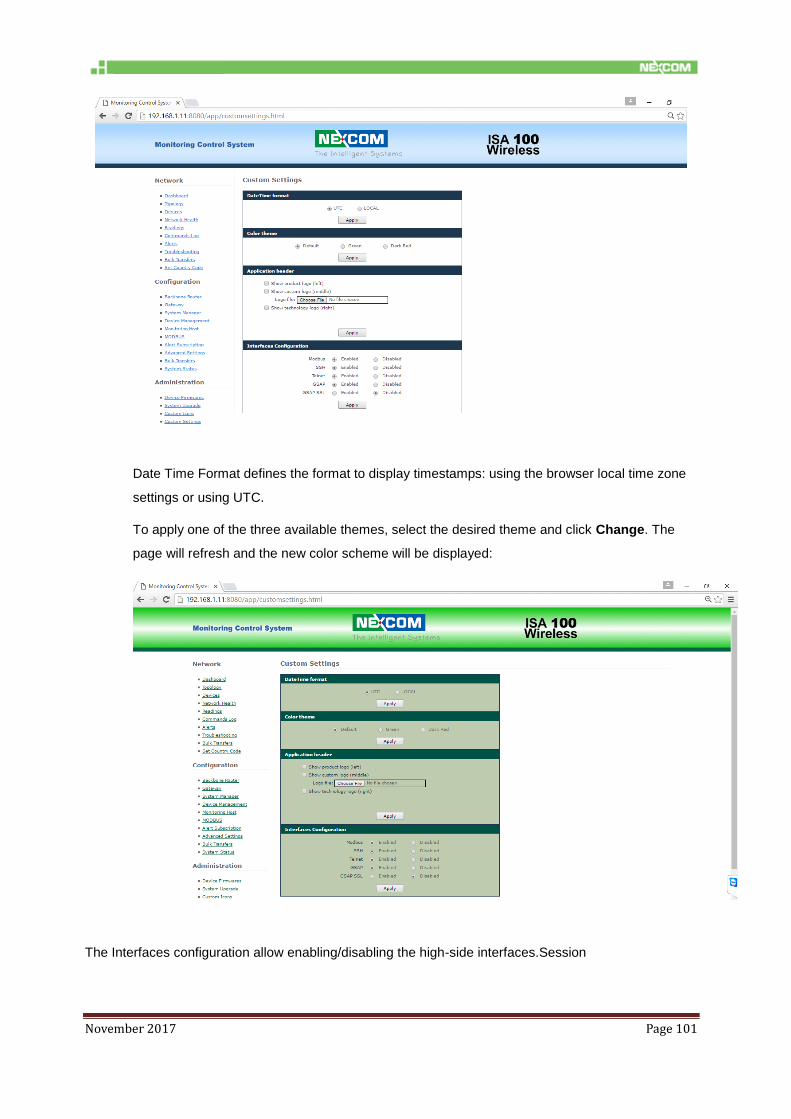
November 2017 Page 101
Date Time Format defines the format to display timestamps: using the browser local time zone
settings or using UTC.
To apply one of the three available themes, select the desired theme and click Change. The
page will refresh and the new color scheme will be displayed:
The Interfaces configuration allow enabling/disabling the high-side interfaces.Session

November 2017 Page 102
8.5 Change Password
This page enables you to change your own password.
Step Action
1. In the form, type your current password in the Old Password field.
2. Type the new password in the New password field.
3. Retype the new password in the Confirm new password field, for verification.
NOTE: The passwords are case sensitive.
4. Click Save at the bottom of the page to save the new password, which will become your
current password.
Tip: To prevent unauthorized persons to gain access to your account, use a strong password in
order to make it difficult for others to determine it and do not disclose your password to anyone.