nickel containingalloypipingforoffshoreoilandgasproduction 10033
TRANSCRIPT
8/13/2019 Nickel ContainingAlloyPipingforOffshoreOilandGasProduction 10033
http://slidepdf.com/reader/full/nickel-containingalloypipingforoffshoreoilandgasproduction-10033 1/21
1
Nickel-containing alloy piping
for offshore oil and gasroduction
By G.L. Swales and B. Todd
G.L. Swales, ARSM, BSc, FIM, C. Eng., and B. Todd, M. Eng., C. Eng., FIM, FIMarE, are consultants to the Nickel Development InstituteEuropean Technical Information Centre, Birmingham, England
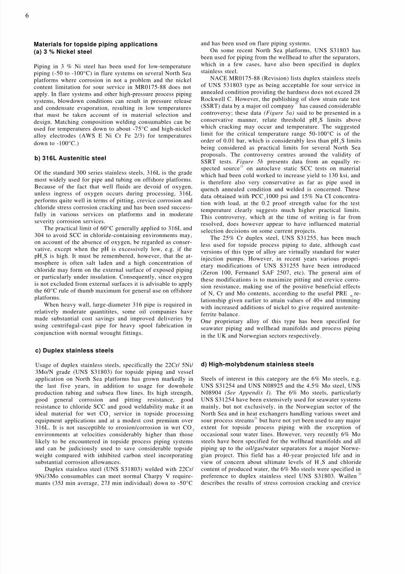
INTRODUCTIONAn increasing share of world oil and gas production is now obtained from offshore areas. Improving technology is al-lowing economic production from deposits in increasingly deep waters and severe weather conditions.
Development of such deposits has emphasized the need for equipment giving high reliability and low maintenancecosts. A key approach to satisfy this need is by the use of corrosion-resistant alloy material and there has been a markedincrease in the use of such material over the last 10 years in the offshore industry. The corrosive environments favoring
alloy material are seawater and oil and gas containing carbon dioxide and/or hydrogen sulphide.Most of the alloy material used is for piping and the purpose of this paper is to consider the technical (including fab-rication) and economic factors influencing the choice of nickel-containing alloy piping. Both topside and subsea system(excluding down-hole) applications are considered in stainless steels (standard austenitic, duplex and high-alloygrades), nickel-base alloys and cupronickels. Systems considered include topside seawater and process systems, under-sea alloy pipelines and topside and subsea manifolds.
Reduction of topside weight is important offshore as it gives cost savings by allowing reduction in deck structuralsteel and jacket steel weights. 1 Use of alloy piping often gives weight and hence cost savings which improves its eco-nomics. The value of weight saving varies with each project and can be very significant.

8/13/2019 Nickel ContainingAlloyPipingforOffshoreOilandGasProduction 10033
http://slidepdf.com/reader/full/nickel-containingalloypipingforoffshoreoilandgasproduction-10033 2/21
2
A) Seawater systems
a) Aerated seawater systems
i) General
Offshore platforms use large amounts of seawater for firefighting, cooling and water injection (to enhance oil recov-ery), production of potable water, sanitation, etc. The sys-tems to handle this involve large tonnages of piping as wellas pipe fittings, pumps, valves, etc.
Early platforms, in shallow areas with mild climates,were built with galvanized steel and cast iron systems. Inflowing seawater corrosion rates of lmm/year are commonlyexperienced in these materials so that after a few years piperenewals are needed. 2
As the corrosion rate is related to seawater velocity,design flow rates are usually limited to 2-2½m/sec.
Development of the North Sea area followed early Ameri-can practice and galvanized steel piping was often used. This
proved unsatisfactory because maintenance in the severeweather conditions commonly experienced in the North Seaproved very expensive and the industry turned to systemsbased on 90/10 cupronickel as used on board ship. Morerecently, high-alloy stainless steels have been used.
ii) 90/10 Cupronickel* piping – designconsiderations
In designing systems with 90/10 cupronickel, flow velocity isagain a limiting factor as high flow rates can give rise tosevere turbulence in areas downstream from short radiusbends, partly throttled valves, etc. This can give rise to cor-rosion-erosion (impingement attack) in 90/10 cupro- nickel.
It is essential, therefore, to design systems at flow rateswhich are acceptable to the alloy even when some turbulenceoccurs – as this is present to a degree in all seawater systems.The flow rates chosen are those given in British StandardBSMA-18 3.
This standard allows flow rates of up to 3 m/sec in pipesizes above 100mm nominal bore, i.e. considerably higherthan in galvanized steel. This gives both s aving in weight andcost as the pipe diameters are significantly less than in a steelsystem.
The early cupronickel systems were designed in accor-dance with BS 3351:1971 4 and thicknesses were based on thestress values in this standard. A later amendment adoptedASME Code V111-UG101-Bursting Test which required abursting pressure of 5 times maximum design pressure. Asdesign pressures up to 20 bar are required for fire mains thenwall thicknesses up to that required for 100 bar burstingpressure are used. 5,6
v) Stainless steel seawater systems
Interest in the use of stainless steels for seawater systems
developed in Norway11
where, in concrete gravity platforms,which incorporate oil storage/seawater ballast tanks in theirbase, problems developed in cement-lined steel ballast pip-ing. This piping is alternately exposed to seawater and crudeoil containing some sulphides. These conditions causedbreakdown and spalling of the cement-linings with subse-quent corrosion of the steel pipe.
Although 90/10 cupronickel would have been technicallysuitable for the seawater exposure, it would be less satisfac-tory when exposed to sulphide-containing oil. This is be-cause sulphides are incorporated into the films on the alloymaking them less protective. A pipe with such a filmexposed to aerated seawater can suffer serious corrosion.
Although stainless steels are resistant to sulphides, thestandard austentic grades such as Type 316 are prone topitting and crevice corrosion in chloride-containing waterssuch as seawater. It was necessary, therefore, to select animproved stainless steel and a 21% Cr 18% Ni 6% Mo + Nalloy, was selected.
This decision stimulated interest in stainless steels forseawater systems and a detailed and comprehensive study ofa large number of stainless steel and nickel-based alloys hasbeen carried out by Shell. 12 This includes laboratory investi-gations and pipe system loops to study both materials andcomponents in seawater. This indicates that high-perform-ance duplex and 6% molybdenum austentitic steels are suit-able for seawater systems.
iii) 90/10 Cupronickel – fabrication
The largest diameter piping required by the offshore indus-try was beyond the size range for seamless piping (normallimit 16") and fabrication from plate using longitudinalseam welds was developed.
The welds are 100% radiographed to ASME Code SectionV111 UW51 to give a joint factor of 1.0. 5 70/30 cupronickel
TOPSIDE PIPING is normally used for the welding consumable as this gives aweld with slightly better corrosion resistance and strengththan the parent plate. GTAW, GMAW, SMAW, and SAWprocesses have all been used but the first three are the mostcommon. In all cases, filler metal is required which con-tains additions such as manganese and titanium to reactwith oxygen and nitrogen which would otherwise give po-rosity in the weld.
Certain impurities which can occur in the alloy can pro-mote heat-affected zone cracking. Reputable manufacturersof the alloy and of welding consumables are aware of thisproblem and control impurity levels in their products tominimize the risk of cracking.
When plate and welding consumables from such manufac-turers are used, then 90/10 cupronickel has good weldability. 7
iv) 90/10 Cupronickel – experience
Many thousands of tonnes of 90/10 cupronickel piping havebeen supplied to the offshore industry during the last 15
years. Where these systems were designed and fabricated inaccordance with the standards and recommendations givenabove and have used valve, pump, etc. materials compatiblewith the piping, 8 they have performed well and failures havebeen minimal. 9,10 Reference 10 records only nine cases of fail-ure over a 20-year period, mostly caused by excessive turbu-lence and polluted seawater during service or commissioning.
Figure 1 shows 90/10 cupronickel for use in seawaterhyperfilters on an offshore platform.
*Details of composition and properties for materials r eferred to in the text are given in Appendix 1

8/13/2019 Nickel ContainingAlloyPipingforOffshoreOilandGasProduction 10033
http://slidepdf.com/reader/full/nickel-containingalloypipingforoffshoreoilandgasproduction-10033 3/21
3
vi) Stainless steels – corrosion resistance inseawaterStainless steels exposed to seawater, particularly in shieldedareas, are prone to pitting and crevice corrosion. Resistanceto this localized attack is improved if the chromium, molyb-denum and nitrogen contents are increased. For most austen-itic grades, the chromium content is about 20% and at thislevel, about 6% molybdenum and 0.15% nitrogen are needed
to give an alloy virtually complete resistance to crevice cor-rosion in seawater. Detailed studies on the effect of alloyingelements have been carried out by various researchers, nota-bly Oldfield, 13 and a ranking of various alloys can be deri vedfrom his mathematical model. However, useful comparisonscan easily be made using the Pitting Resistance Equivalent
Number , PRE N
14 which is usually calculated as follows:-
PRE N = Cr% + 3.3 Mo% + 16 N%
The higher this number, the greater the resistance to crevicecorrosion. The PRE N indicates the marked influence ofmolybdenum and nitrogen.
A PRE N of at least 40 is considered necessary in an alloy tohave sufficient resistance in aerated seawater for criticalapplications such as piping and heat exchanger tubing.
PRE N for some stainless steels are given in Table 1 and Appendix 1
Table1Pitting resistance equivalent number nominal
composition
Alloy Cr% Mo% N% Ni% Other% PRE N
UNS S31603 17 2.5 - 12 - 25.25UNS N08904 20 4.5 - 25 1.5 CU 34.85UNS S31254 20 6.0 0.2 18 0.8 CU 43.0UNS N08925 21 6.0 0.15 25 - 43.2
UNS N08367 21 6.5 0.2 25 - 45.65
General corrosion of stainless steels in seawater is ex-tremely low and no corrosion allowance is necessary.In fast flowing seawater, stainless steels remain passive andprovided cavitation is avoided, the surface remains unattackedat velocities well above those used in piping systems. Table 2provides data on some standard austenitic grades; the resultsare typical for all stainless steels.
Table 2Stainless steel Seawater velocity Corrosion rate
grade m/s microns/year
304 43 5316 43 5
Alloy 20 41 15
vii) Stainless steel seawater systems – designconsiderations.
Based on the corrosion data in Section vi) it is clear that themain corrosion consideration influencing the selection ofstainless steel seawater piping is resistance to crevice corro-sion as both general corrosion and corrosion-erosion lossesare negligible. Also, stress-corrosion cracking is not a prob-lem as ambient temperature seawater does not reach the*Trademark
widely accepted 60°C temperature limit below which crack-ing does not occur.
Table 1 indicates that materials such as UNS S31254,N08925 and N08366 should be suitable for seawater systemsand extensive use has been made of Avesta 254SMO* (UNSS31254) in two Norwegian projects.
In designing these systems, account was taken of both thehigh flow resistance and high strength of the alloy to reduce
both pipe diameter and thickness.Pumping costs increase with flow rate and a compromise
between reduced pipe cost and increased pumping costs isnecessary. Statoil, Norway, designed their systems at 7m/sec– this limit also being influenced by the noise generated bythe flowing seawater. 15
For design, allowable stresses were based on NorwegianCode TBK6 which allows a safety factor of 2.4 for UTS and1.35 for yield stress compared with 3.0 and 1.5 respectivelyfor ANSI B31.3. For UNS 31254 this allowed a design stressof 170 N/mm 2 for TBK6 compared with 153 N/mm 2 for ANSIB31.3.
viii) Stainless steel seawater systems – serviceexperience
Although small amounts of 6% Mo stainless steels havebeen used satisfactorily in various offshore applicationssince 1979, the first major usage was in the Gullfaks andOsberg fields in Norway. Approximately 5000 tonnes of Avesta254SMO piping has been used for those fields and performancehas been satisfactory. The first platform – Gullfaks A – wasinstalled in 1986.The effect of high flow rate and design stress on the size andweight of two pipe system components is shown in Table 3.
Figure 2 shows part of the fire system in Avesta 254SMOon Gullfaks A.
A more recent development has been the use of a duplexstainless steel for a United Kingdom project – AmeradaHess, Ivanhoe and Rob Roy fields. The alloy selected isZeron* 100 (24% Cr 4% Mo 0.2 N 0.8% W 7% Ni). Thisalloy has a PRE N over 40 and consequently should havesufficient corrosion resistance for pipe systems handlingaerated seawater. These systems have recently entered serv-ice.
There are now several of these high-performance duplexalloys available in wrought and cast form, e.g. SAF 2507,Fermanel*, Uranus* 47N, Sumitomo DP3*, etc.
b) Dearated seawater systemsi) General
Many offshore platforms are fitted with water injection sys-tems to improve the production profile of the field and toincrease oil production. These systems require largevolumes of water which must be filtered and treated toremove bacteria such as sulphate reducers that could causethe field to go sour.
Oxygen is also removed to reduce the corrosivity of theseawater.
These systems operate at high pressures (100* bar) andcorrosion rates must be low or mechanical failure wouldresult.

8/13/2019 Nickel ContainingAlloyPipingforOffshoreOilandGasProduction 10033
http://slidepdf.com/reader/full/nickel-containingalloypipingforoffshoreoilandgasproduction-10033 4/21
4
Table 3
Size
Stainless steelWallthicknessmm
Weighttonnes Size
CupronickelWallthicknessmm
Weighttonnes
Seawater lift discharge 14" 4.78 2.7 (d) 20" 7.5 5.8 (d)from pumps: 6m pipe +3 flanges and 1 valveper pump. 14" 4.78 5.5 (w) 20" 7.5 11.5 (w)
Seawater lift header 20" 6.35 18.7 (d) 36" 8 37.7 (d)180m straight pipe 20" 6.35 77.9 (w) 36" 8 151.7 (w)
* (d) = dry(w) = wet
ii) Corrosion in deaerated seawater
The authors 16 have published a detailed study of corrosion ofcarbon steel and stainless steels in deaerated seawater. Fig-ure 3 from this study shows how corrosion rate is influencedby oxygen content and flow rate in a 150mm diameter carbonsteel pipe. This shows that high corrosion rates can occur atmoderate flow rates (2 m/sec) at less than 50 ppb oxygen.For acceptable corrosion rates, deaeration to oxygen levelsbelow 10 ppb is necessary. Also, for high flow rates, such asare experienced in pumps and partly throttled valves,corrosion rates on carbon steel are unacceptably high andalloy materials should be used.
Stainless steels are resistant to pitting and crevice corro-sion in deaerated seawater as, at neutral pH, these phenom-ena are dependent on the setting up of differential aerationcells. At low oxygen levels, such cells are ineffective. Table4 provides data for natural aerated (typically 8ppm) and hotdeaerated seawater for Type 316 stainless steels.
In considering corrosion in deaerated systems, attentionmust be paid to the presence of other oxidizing species inthe seawater, notably chlorine. It is common practice to adda biocide to seawater after deaeration. If chlorine is used forthis treatment it will, from the corrosion viewpoint, have a
similar effect to adding oxygen and severe corrosion canoccur 16 . A nonoxidizing biocide is preferred for deaeratedseawater.
iii) Deaerated seawater systems – materialsselection.
A water injection system consists of lift pumps, pipingvalves, etc. coarse and fine filters, a deaeration tower, upto the deaerator, is similar to the seawater syst ems describedunder Topside piping and the same alloy material selectionis advised, i.e. 90/10 cupronickel or 6% Mo austenitic stain-less steel. Materials for pump, filters, etc. should be compat-ible with the chosen pipe material.
After deaeration, which is achieved physically (in thedeaerator) and chemically (by addition of sulphite or bi-sulphite), the corrosivity of the seawater is greatly reduced.Piping in carbon steel can be used, provided the oxygenlevel is low (see Section i above) but where high flow ratesare experienced, then stainless steels are required, for ex-ample, in pumps, valves and reducers. Because of the highpressures, duplex stainless steels are often used for largercomponents as their high strength allows significant weightsaving. Proprietary higher alloy duplex stainless steels areoften used for injecti on pumps as they have higher resistanceto pitting and crevice corrosion – examples are Ferralium*255-3SC, Noradur*, Zeron 25 and 100, etc.
B. Process pipework(a) General considerations
Compared with a decade ago, the increased amount of
corrosion-resistant steels and alloys now being used fortopside process piping and vessels, replacing carbon steelwith substantial corrosion allowances and inhibitors, is quiteremarkable.
The economics of the use of corrosion inhibitors offshoreis entirely differ ent to that for onshore installations. The life-cycle cost of inhibition is high in offshore usage sinceinhibitor cost, storage and transportation costs all have to betaken into account as well as manpower for supervision andmaintenance of injection equipment. Since reduction intopside weight is a key aim of offshore engineering planningin order to save on supporting structure costs, the additionalweight associated with inhibitor usage and the substantial
*Trademark
Table 4, 13,17
Corrosion of Type 316 stainless steel in aerated anddeaerated seawater
Environment Exposure time Velocity Generalcorrosion
days m/sec or pittingNatural N. Atlanticseawater 486 0 2.4mm P
Deaerated seawater105 ºC 25 ppb O 2
547 0 0.12mm P
Natural N. Atlanticseawater 30 37 0.009mm/yr G
Brine pH 7.8 25 ppb O 2 at 50 ºC 133000 ppm CL. 8 40 0.027mm/yr G
P – Pitting G – General
8/13/2019 Nickel ContainingAlloyPipingforOffshoreOilandGasProduction 10033
http://slidepdf.com/reader/full/nickel-containingalloypipingforoffshoreoilandgasproduction-10033 5/21
8/13/2019 Nickel ContainingAlloyPipingforOffshoreOilandGasProduction 10033
http://slidepdf.com/reader/full/nickel-containingalloypipingforoffshoreoilandgasproduction-10033 6/21
6
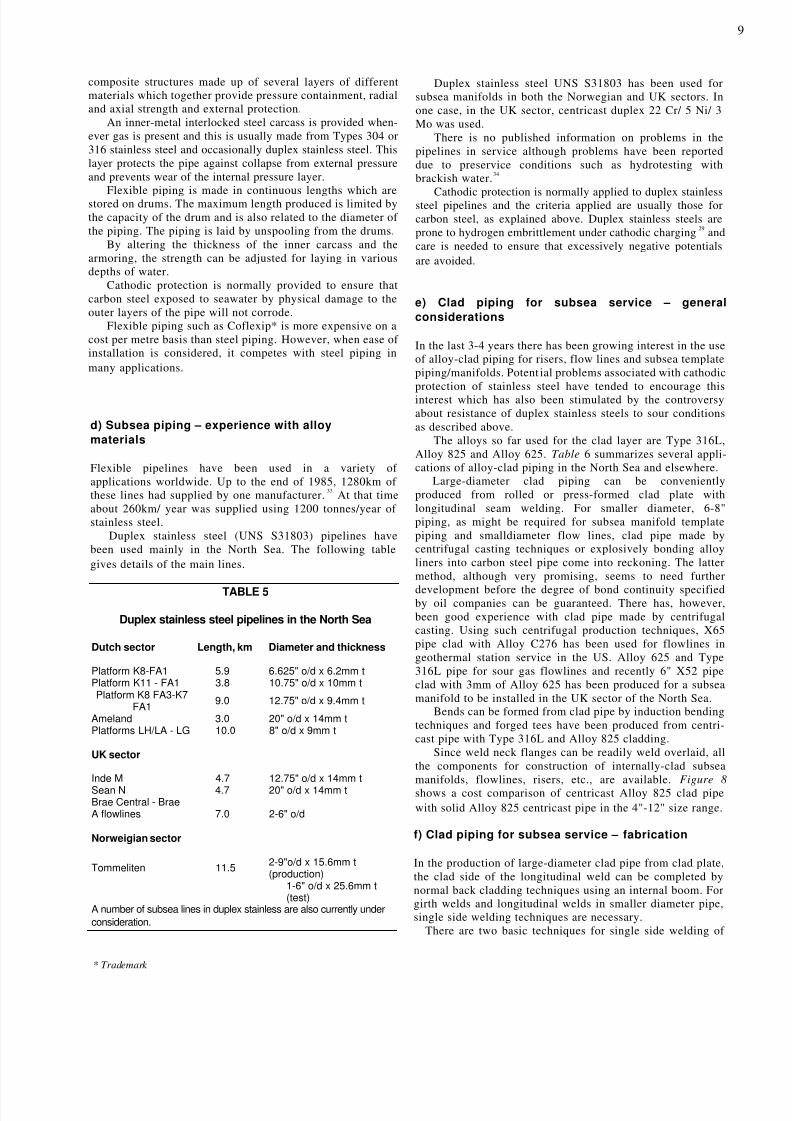
Materials for topside piping applications(a) 3 % Nickel steel
Piping in 3 % Ni steel has been used for low-temperaturepiping (-50 to -100°C) in flare systems on several North Seaplatforms where corrosion in not a problem and the nickelcontent limitation for sour service in MR0175-88 does notapply. In flare systems and other high-pressure process piping
systems, blowdown conditions can result in pressure releaseand condensate evaporation, resulting in low temperaturesthat must be taken account of in material selection anddesign. Matching composition welding consumables can beused for temperatures down to about -75°C and high-nickelalloy electrodes (AWS E Ni Cr Fe 2/3) for temperaturesdown to -100°C.)
b) 316L Austenitic steel
Of the standard 300 series stainless steels, 316L is the grademost widely used for pipe and tubing on offshore platforms.Because of the fact that well fluids are devoid of oxygen,unless ingress of oxygen occurs during processing, 316L
performs quite well in terms of pitting, crevice corrosion andchloride stress corrosion cracking and has been used success-fully in various services on platforms and in moderateseverity corrosion services.
The practical limit of 60°C generally applied to 316L and304 to avoid SCC in chloride-containing environments may,on account of the absence of oxygen, be regarded as conser-vative, except when the pH is excessively low, e.g. if thepH 2S is high. It must be remembered, however, that the at-mosphere is often salt laden and a high concentration ofchloride may form on the external surface of exposed pipingor particularly under insulation. Consequently, since oxygenis not excluded from external surfaces it is advisable to applythe 60°C rule of thumb maximum for general use on offshoreplatforms.
When heavy wall, large-diameter 316 pipe is required inrelatively moderate quantitites, some oil companies havemade substantial cost savings and improved deliveries byusing centrifugal-cast pipe for heavy spool fabrication inconjunction with normal wrought fittings.
c) Duplex stainless steels
Usage of duplex stainless steels, specifically the 22Cr/ 5Ni/3Mo/N grade (UNS S31803) for topside piping and vesselapplication on North Sea platforms has grown markedly inthe last five years, in addition to usage for downholeproduction tubing and subsea flow lines. Its high strength,
good general corrosion and pitting resistance, goodresistance to chloride SCC and good weldability make it anideal material for wet CO 2 service in topside processingequipment applications and at a modest cost premium over316L. It is not susceptible to erosion/corrosion in wet CO 2 environments at velocities considerably higher than thoselikely to be encountered in topside process piping systemsand can be judiciously used to save considerable topsideweight compared with inhibited carbon steel incorporatingsubstantial corrosion allowances.
Duplex stainless steel (UNS S31803) welded with 22Cr/9Ni/3Mo consumables can meet normal Charpy V require-mants (35J min average, 27J min individual) down to -50°C
and has been used on flare piping systems.On some recent North Sea platforms, UNS S31803 has
been used for piping from the wellhead to after the separators,which in a few cases, have also been specified in duplexstainless steel.
NACE MR0175-88 (Revision) lists duplex stainless steelsof UNS 531803 type as being acceptable for sour service inannealed condition providing the hardness do es not exceed 28
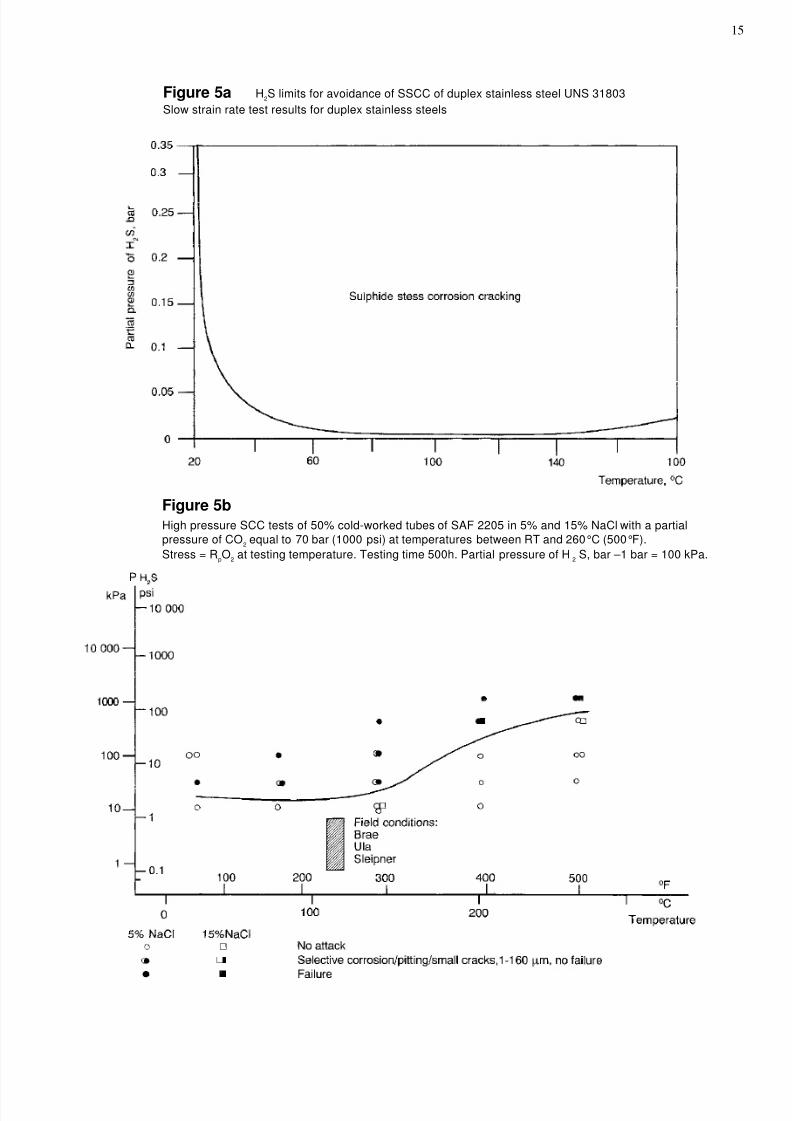
Rockwell C. However, the publishing of slow strain rate test(SSRT) data by a major oil company 21 has caused considerablecontroversy; these data (Figure 5a) said to be presented in aconservative manner, relate threshold pH 2S limits abovewhich cracking may occur and temperature. The suggestedlimit for the critical temperature range 50-100°C is of theorder of 0.01 bar, which is considerably less than pH 2S limitsbeing considered as practical limits for several North Seaproposals. The controversy centres around the validity ofSSRT tests. Figure 5b presents data from an equally re-spected source 11 on autoclave static SCC tests on materialwhich had been cold worked to increase yield to 130 ksi, andis therefore also very conservative as far as pipe used inquench annealed condition and welded is concerned. Thesedata obtained with PCC 21000 psi and 15% Na CI concentra-tion with load, at the 0.2 proof strength value for the testtemperature clearly suggests much higher practical limits.This controversy, which at the time of writing is far fromresolved, does however appear to have influenced materialselection decisions on some current projects.
The 25% Cr duplex steel, UNS S31255, has been muchless used for topside process piping to date, although castversions of this type of alloy are virtually standard for waterinjection pumps. However, in recent years various propri-etary modifications of UNS S31255 have been introduced(Zeron 100, Fermanel SAF 2507, etc). The general aim ofthese modifications is to maximize pitting and crevice corro-sion resistance, making use of the positive beneficial effectsof N, Cr and Mo contents, according to the useful PRE N re-
lationship given earlier to attain values of 40+ and trimmingwith increased additions of nickel to give required austenite-ferrite balance.One proprietary alloy of this type has been specified forseawater piping and wellhead manifolds and process pipingin the UK and Norwegian sectors respectively.
d) High-molybdenum stainless steels
Steels of interest in this category are the 6% Mo steels, e.g.UNS S31254 and UNS N08925 and the 4.5% Mo steel, UNSN08904 (See Appendix I). The 6% Mo steels, particularly
UNS S31254 have been extensively used for seawater systemsmainly, but not exclusively, in the Norwegian sector of theNorth Sea and in heat exchangers handling various sweet andsour process streams 21 but have not yet been used to any majorextent for topside process piping with the exception ofoccasional sour water lines. However, very recently 6% Mosteels have been specified for the wellhead manifolds and allpiping up to the oil/gas/water separators for a major Norwe-gian project. This field has a 40-year projected life and inview of concern about ultimate levels of H 2S and chloridecontent of produced water, the 6% Mo steels were specified inpreference to duplex stainless steel UNS S31803. Wallen 21 describes the results of stress corrosion cracking and crevice

8/13/2019 Nickel ContainingAlloyPipingforOffshoreOilandGasProduction 10033
http://slidepdf.com/reader/full/nickel-containingalloypipingforoffshoreoilandgasproduction-10033 7/21
7
corrosion tests on UNS S31254 in simulated sour environ-ments. The 4.5% Mo steel UNS N08904 has been used on anumber of platforms in the form of clad heavy-section platemainly for separator vessels, but also for associated piping.
e) Medium and high-nickel alloys
The materials of major interest in medium nickel alloy cate-
gory are Alloy 825 (UNS N08825) and Alloy 28 (UNSN08028). In the higher nickel category Alloy 625 (UNSN06625) and Alloy G (UNS N06007) find application.
Alloy 825 has been fairly extensively used for processpiping up to and including the separators on a number of oiland gas platforms in the UK sector of the North Sea sincethe beginning of the decade. It has been used in moderatelysevere conditions up to 30% CO 2 100 ppm H 2S 500 bar at upto100°C mainly on the grounds of expected good resistanceto stress corrosion cracking. Alloy 825 has a relatively lowPRE N and a high Mo (5%) version to improve the PRE N hasbeen offered but to the authors' k nowledge not used. It wouldappear that Alloy 825 has adequate pitting resistance underthe anerobic conditions involved and has given good service.
Popperling 24 reports SCC cracking test data in 5M Na CIwith 10 bar H 2S, 20 bar Co 2 170 bar N 2 in which cold workedAlloy 825 (119 ksi) did not 2 crack at loads up to the 0.2%proof stress (at temperature) at exposure temperatures up toand including 200°C, a temperature not likely to be exceededin normal topside processing applications.
Figure 4 shows test (10") and production (16") manifoldsin Alloy 825 for a UK sector oil platform. The manifold runpipe (up to 32mm thick) is in centrifugally-cast Alloy 825giving considerable cost savings and delivery improvementscompared with wrought pipe. Centrifugally-cast Alloy 825manifolds are also being used on a gas product ion platform inthe southern North Sea and are under consideration for atleast one other current project. Cast Alloy 825 differs fromwrought Alloy 825 principally in that it is niobium- rather
than titanium-stabilized for foundry reasons. Centifugally-cast Alloy 825 readily matches the wrought alloy in 0.2%proof strength but tends to have a lower minimum UTS.However, applying ANSI 31.3 code, which is the code usedgenerally for process piping design, at least in the UK sectorthe allowable design strength is yie ld contro lled and inconsequence the cast alloy has identical allowable designstress to the wrought alloy. In ANSI B31. 3 a casting factor of0.8 is applied but this can be raised to 1.0 if the cast pipe ismachined inside and out, (normal practice for centrifugally-cast pipe), dye-penetrant tested inside and out and radio-graphed, in which case cast pipe can replace wrought Alloy825 without design penalty.
In spite of additional quality control, the cost saving inthese instances was very substantial indeed.
The Norwegian specification TBK6 does not specificallymention cast pipe materials but application of their designstress criteria would result in the same conclusion, i.e. it is
yie ld contro lled.The refining and petrochemical divisions of oil companies
have for many years used centricast alloy piping for criticalapplications and it would seem that production divisions ofsome companies are now recognizing there is a niche forcentrifugal casting for heavy wall alloy piping spools andmanifolds, particularly when only relatively small tonnagesof heavy wall, large-diameter pipe is required.
Piping internally clad with Aloy 825 is being consideredfor process piping applications; tees and bends can be pro-duced from clad pipe and clad weld neck flanges by overlay-ing techniques. Clad pipe 4" and above can be made bycentrifugal casting methods and this will be referred to in thesection on subsea lines.
One other application for Alloy 825 is gas turbine exhaustpiping, where the chloride in the atmosphere can cause
external SCC of less resistant alloys.Alloy 28 has been quite extensively used in the coldworked condition (120 ksi) for production tubing casing andlines in sour wells in Texas, Louisiana, Florida and the Gulfof Mexico. To date it has not been widely used in the NorthSea and north European oilfields, although it is a Europeandevelopment.
It has been used for handling very sour production water ina German field and for chemical dosing pipe systems onNorth Sea platforms. It is now receiving wider considerationin some companies for severe corrosion service since uncer-tainty has been created regarding the suitability of duplexstainless steel as referred to earlier.
The high chromium content (28%) in conjunction with3 % Mo confers good pitting resistance (PRE N - 39).
SCC tests, 22,24 in simulated well fluids indicate the alloy tohave exceptionally good cracking resistance up to 300°C.
A higher Mo variant (6%) has recently been announcedand this would be expected to enhance pitting and crevicecorrosion resistanace even further.
Major applications of Alloy 625 piping on offshore plat-forms are not numerous. Extensive use was, however, madeof the alloy in piping systems of a molecular sieve dryingunit for a combination of reasons:
a) Mechanical design considerations over a relativelywide design temperature range (-70° to +350°C)
b) The need for outstanding general and localized
corrosion resistance in aggressive, low pH, highchloride media containing H 2S
c) Resistance to chloride SCC and sulphide SCCsour, high chloride environments.
Alloy 625 has also been used for waste water drainshandling low pH high chloride effluent. Alloy 625 has out-standing crevice corrosion resistance in acid chlorides. 13
It has, however, been extensively used in supplementaryapplications - e.g., weld overlaying and welding corrosion-resisting alloys. Alloy 625 is exceptionally amenable tooverlaying using TIG or synergic pulsed MIG welding whichis extensively used for inter nal overlaying of valves and othercomponents and surfacing of heat exchanger tube sheets, etc.Alloy 615 welding wire and electrodes (ER Ni Cr Mo 3 + ENi Cr Mo 3) are extensively used for providing weld metalsovermatching in corrosion resistance for alloys such as UNSS31254 and UNS N08925, UNS N0825. Its welding behavi-our is such that it can be used for heavy section welds, seeFigure 4. It is recommended for welding wrought Alloy 825when section thickness exceed about 19mm.
Alloy 625 clad plate is now available which can beconverted to large diameter pipe by longitudinal welding;and small diameter Alloy 625 clad pipe can be made by cen-trifugal casting techniques.

8/13/2019 Nickel ContainingAlloyPipingforOffshoreOilandGasProduction 10033
http://slidepdf.com/reader/full/nickel-containingalloypipingforoffshoreoilandgasproduction-10033 8/21
8
a) General
Alloy materials, usually stainless steels, but sometimes nickel-base alloys, have been used for subsea pipelines and flowlines. Both rigid metal and flexible metal/nonmetal lines havebeen used.
Manifolds for subsea completions, as well as those onplatform topsides, are essentially part of the piping systemand are often made from alloy material.
b) Subsea piping – duplex stainless steel
Some gas deposits contain appreciable amounts of carbondixiode. This can give rise to serious corrosion of carbonsteel in areas where water phases are present – sweet gascorrosion. De Waard and Milliams 25 have made a detailedstudy of corrosion of carbon steel in CO 2 /wat er envi ronmentsand their work has allowed reasonable predictions of corro-sion rates in service to be made.
Although inhibitors are sometimes effective in reducing
corrosion in carbon dioxide, in other cases they are eitherineffective or uneconomic.
Studies by Milliams 26 showed that chromium-containingalloys had high resistance to sweet gas corrosion and follow-ing successful service on land; in-field lines in duplexstainless steel UNS S31803 (W.N. 1.4462 22% Cr 5% Ni 3%Mo + N) were fitted in several of NAM's Netherlandsoffshore fields.
i) Duplex stainless steel pipelines – economicconsiderations
Although duplex stainless steel piping is considerably moreexpensive than carbon steel, other factors enable it to be usedeconomically. These are:
1) The ability to produce corrosive gas from a subseacompletion or a simple platform, and to convey ituntreated to a process plant, saves platform andequipment costs.
2) Elimination of inhibitors, their storage and injectionfacilities gives significant savings.
A detailed analysis of the economics of usage on a Dutchfield has been published by Groenewoud. 27 Figure 6 com-pares costs for stainless steel flowlines with centralizedprocessing, and carbon steel flowlines with drying installa-
tions, on each platform and establishes a breakeven distanceof 8km for the use of stainless steel. As the actual distanceswere less than this, two stainless steel lines were fitted.
ii) Duplex stainless steel pipelines – fabricationand installation
Duplex stainless steels are designed to have a microstructureconsisting of 50% ferrite and 50% austenite. Weldmentsshould aim to retain a roughly similar balance. High coolingrates, as can occur with low heat inputs, can produce a weldheat affected zone with high (90%+) ferrite content. The
SUBSEA PIPING SYSTEMS weld metal is subject to similar considerations and in orderto obtain a weld deposit with an acceptable ferrite/austeniteratio, it is necessary to increase the amount of austenitestabilizer–usually nickel–in weld consumables. Standardconsumables have generally been of the 22 Cr/ 9 Ni/ 3 Motype but there are now trends to higher chromium (25%) highnitrogen (0.3%) to give improved corrosion resistance in theweld bead – (PRE N 38 approximately). Autogenous welds
are best avoided. A high heat input can result in highaustenite contents and precipitation of nitrides in the heat-affected zone.
Welding processes are usually restricted to heat inputbetween 0.5 and 2.5kj per mm. As these heat inputs are lowin comparison with carbon steels, and specified interpasstemperatures are also lower, welding tends to be slow andthis increases pipeline costs due to pipe barge rental charges.To reduce time offshore, stainless steel piping is often pre-fabricated ashore into longer lengths. In the case of the ShellSean and Indefatigable fields, 40-ft. lengths were double-
jointed onshore; nevertheless , the 20" lines were laid at only0.65km/day compared with 3km/day for carbon steel . 26 (Fig-ure 7) shows the Sean/Indefatigable line during laying). Forshort flowlines, welding onshore and towing to site providesan economic alternative to high-cost barge welding.
Because of this high cost of welding there is an incentiveto develop alternative methods. One such method is forgewelding, e.g. SAG forge welding which is receiving attentionin Norway. Another is flash butt welding; to the authors'knowledge, neither has yet been used commercially in theNorth Sea. References 30 and 31 give a good review ofwelding duplex stainless steels.
For small-diameter flowlines, considerat ion has been givento reel laying of duplex stainless steel; this has not yet beendone in practice but is under consideration for laying flow-lines from a subsea production installation to a productionplatform in the UK sector. Crucial to the performance of thepiping is a high quality root run and GTAW welding is
normally used. Shielding and purge gas is normally pureargon. Hydrogen additions to the gases must be avoided asthis can lead to embrittlement of the material. With a goodquality root run in place the joint can be filled with higherproduction processes such as GMAW and SMAW.
To avoid contamination of the stainless steel surfaceduring fabrication, all clamps, wires, brushes, etc. should bemade from stainless steel.
For corrosion protection the piping, after fabrication, iscovered with a 4mm layer of polyethylene and a 50mm-thickconcrete buoyancy coat. These are put on the pipes beforelay-barge welding, only the weld area being left open andcovered before laying.
In case of damage to these coatings, which couldresult in a severe crevice attack in the polyethylene/metalcrevice, cathodic protection using sacrificial anodes isusually provided. As the line is normally connected tocarbon steel, then the protection potential chosen is usuallythat for steel, i.e. - 850 my Ag/AgCl. Care is needed to avoidmore negative potentials as there is a risk of hydrogenembrittlement in duplex stainless steels . 29
c) Subsea piping – flexible piping
Flexible flowlines, risers, umbilicals and similar applica-tions have been developed for offshore use. 32 These are
8/13/2019 Nickel ContainingAlloyPipingforOffshoreOilandGasProduction 10033
http://slidepdf.com/reader/full/nickel-containingalloypipingforoffshoreoilandgasproduction-10033 9/21
9
composite structures made up of several layers of differentmaterials which together provide pressure containment, radialand axial strength and external protection.
An inner-metal interlocked steel carcass is provided when-ever gas is present and this is usually made from Types 304 or316 stainless steel and occasionally duplex stainless steel. Thislayer protects the pipe against collapse from external pressureand prevents wear of the internal pressure layer.
Flexible piping is made in continuous lengths which arestored on drums. The maximum length produced is limited bythe capacity of the drum and is also related to the diameter ofthe piping. The piping is laid by unspooling from the drums.
By altering the thickness of the inner carcass and thearmoring, the strength can be adjusted for laying in variousdepths of water.
Cathodic protection is normally provided to ensure thatcarbon steel exposed to seawater by physical damage to theouter layers of the pipe will not corrode.
Flexible piping such as Coflexip* is more expensive on acost per metre basis than steel piping. However, when ease ofinstallation is considered, it competes with steel piping inmany applications.
d) Subsea piping – experience with alloymaterials
Flexible pipelines have been used in a variety ofapplications worldwide. Up to the end of 1985, 1280km ofthese lines had supplied by one manufacturer. 33 At that timeabout 260km/ year was supplied using 1200 tonnes/year ofstainless steel.
Duplex stainless steel (UNS S31803) pipelines havebeen used mainly in the North Sea. The following tablegives details of the main lines.
TABLE 5
Duplex stainless steel pipelines in the North Sea
Dutch sector Length, km Diameter and thickness
Platform K8-FA1 5.9 6.625" o/d x 6.2mm tPlatform K11 - FA1 3.8 10.75" o/d x 10mm tPlatform K8 FA3-K7
FA1 9.0 12.75" o/d x 9.4mm t
Ameland 3.0 20" o/d x 14mm tPlatforms LH/LA - LG 10.0 8" o/d x 9mm t
UK sector
Inde M 4.7 12.75" o/d x 14mm tSean N 4.7 20" o/d x 14mm tBrae Central - BraeA flowlines 7.0 2-6" o/d
Norweigian sector
Tommeliten 11.5 2-9"o/d x 15.6mm t(production)
1-6" o/d x 25.6mm t(test)
A number of subsea lines in duplex stainless are also currently underconsideration.
* Trademark
Duplex stainless steel UNS S31803 has been used forsubsea manifolds in both the Norwegian and UK sectors. Inone case, in the UK sector, centricast duplex 22 Cr/ 5 Ni/ 3Mo was used.
There is no published information on problems in thepipelines in service although problems have been reporteddue to preservice conditions such as hydrotesting withbrackish water. 34
Cathodic protection is normally applied to duplex stainlesssteel pipelines and the criteria applied are usually those forcarbon steel, as explained above. Duplex stainless steels areprone to hydrogen embrittlement under cathodic charging 29 andcare is needed to ensure that excessively negative potentialsare avoided.
e) Clad piping for subsea service – generalconsiderations
In the last 3-4 years there has been growing interest in the useof alloy-clad piping for risers, flow lines and subsea templatepiping/manifolds. Potent ial problems associated with cathodicprotection of stainless steel have tended to encourage thisinterest which has also been stimulated by the controversyabout resistance of duplex stainless steels to sour conditionsas described above.
The alloys so far used for the clad layer are Type 316L,Alloy 825 and Alloy 625. Table 6 summarizes several appli-cations of alloy-clad piping in the North Sea and elsewhere.
Large-diameter clad piping can be convenientlyproduced from rolled or press-formed clad plate withlongitudinal seam welding. For smaller diameter, 6-8"piping, as might be required for subsea manifold templatepiping and smalldiameter flow lines, clad pipe made bycentrifugal casting techniques or explosively bonding alloyliners into carbon steel pipe come into reckoning. The lattermethod, although very promising, seems to need further
development before the degree of bond continuity specifiedby oil companies can be guaranteed. There has, however,been good experience with clad pipe made by centrifugalcasting. Using such centrifugal production techniques, X65pipe clad with Alloy C276 has been used for flowlines ingeothermal station service in the US. Alloy 625 and Type316L pipe for sour gas flowlines and recently 6" X52 pipeclad with 3mm of Alloy 625 has been produced for a subseamanifold to be installed in the UK sector of the North Sea.
Bends can be formed from clad pipe by induction bendingtechniques and forged tees have been produced from centri-cast pipe with Type 316L and Alloy 825 cladding.
Since weld neck flanges can be readily weld overlaid, allthe components for construction of internally-clad subseamanifolds, flowlines, risers, etc., are available. Figure 8shows a cost comparison of centricast Alloy 825 clad pipewith solid Alloy 825 centricast pipe in the 4"-12" size range.
f) Clad piping for subsea service – fabrication
In the production of large-diameter clad pipe from clad plate,the clad side of the longitudinal weld can be completed bynormal back cladding techniques using an internal boom. Forgirth welds and longitudinal welds in smaller diameter pipe,single side welding techniques are necessary.
There are two basic techniques for single side welding of

8/13/2019 Nickel ContainingAlloyPipingforOffshoreOilandGasProduction 10033
http://slidepdf.com/reader/full/nickel-containingalloypipingforoffshoreoilandgasproduction-10033 10/21
10
clad pipe which can form the basis of detailed weld proce-dures:
a) Using high alloy consumables for the complete joint.
b) Welding the clad layer first with a GTAW root andreinforcing pass. A buffer layer of very low carbon ironis next deposited and then the joint is completed with
appropriate carbon steel electrodes.Weld overlaying is being used extensively for subsea
system components, e.g. valves, sphere tees in an Alloy 625riser system, external corrosion protection of pipe penetra-tions into concrete structures, etc. Reference 33 describes aparticular application in the shore approach tunnel for theOseberg transportation pipeline.
has poor mechanical properties. A pressure surge can causesudden failure through this layer.
Centricast piping with welded-on flanges are at less risk asthe stresses on the circumferential weld is about half that ofthe longitudinal seam weld described above. Heat treatment–4-8 hours at 675°C–will reduce the tendency to dealumini-fication and is beneficial. However, the susceptibility canonly be removed by a high-temperature treatment which is
not feasible on finished fabrications.Where all-stainless steel pumps are used, as for example instainless steel seawater systems, then alloys with high resis-tance to pitting and crevice corrosion should be used, i.e.alloys with PRE N greater than 40.
MISCELLANEOUS APPLICATIONS
a) Splash zone sheathing of risers
Experience 36 has shown that concrete cladding of hot riserscan be dangerous. The splash zone cladding is prone tophysical damage from floating objects and highly oxygen-ated seawater on the hot metal surface can causecatastrophic corrosion. Serious incidents have occurred inthe Arabian Gulf and in the North Sea 36 resulting inextensive fire damage and in one case well loss.
Splash zones can be protected using metal sheathing – 3-4mm-thick Alloy 400 (70/30 nickel-copper) has been exten-sively used for this purpose. Attachment methods for sheath-ing were reviewed by McKeown 37 .
A recent development has been the use of 90/10 cupro-nickel for sheathing applications. 38
c) Expansion bellows
The use of expansion bellows of multiply alloy constructionto compensate for expansion or contraction in piping systemsoperating at elevated temperatures or subzero temperaturesrespectively is well established practice in all sectors ofprocess industry and platform topside process piping is noexception. A typical example on offshore platforms would begas turbine exhaust systems.
The 300 series austenitic stainless steels, e.g. Type 316L,304L, have long been important materials for expansion bel-lows. However, their susceptibilility to chloride stress corro-sion cracking at elevated temperatures when handling chlo-ride-containing fluids or operating in a salt-laden atmos-phere has lead to the widespread use of high-nickel alloys(nickel having the property of increasing resistance to chlo-ride stress corrosion cracking) 39 for this application, prin-cially Alloy 825 or Alloy 625. In Europe bellows manufac-turers have tended to specify mainly 825 for standard prod-ucts although Alloys 625 and 400 find some usage whereastheir US counterparts have generally opted for Alloy 625.
b) Pump columns
Vertical lift pumps are commonly used to deliver seawaterto the platform. The casing and impeller are located belowthe low tide level at the end of a series of vertical columnpipes which are fastened to the jacket. These column pipesare essentially part of the piping system.
Alloy materials commonly used for these pipes are Ni-Resist cast iron (the D-2 grade is widely used) and nickelaluminum bronze (both wrought and cast grades).
Ni-Resist is anodic to stainless steels and providescathode protection which is particularly useful duringshutdown periods. Pumps often use Type 316 stainless steelfor the shafting with the cast equivalent (CF-3M or CF-8M)for the impeller. During operation, the high resistance of thestainless steel to fast-flowing seawater is beneficial andpitting is not a problem during shutdowns.
Ni-Resist irons for use in warm seawater should be stressrelieved (1 hour at 650°C followed by cooling) to minimizethe risk of stress corrosion cracking.
Nickel aluminum bronze has been used for pump colums,particularly where the same alloy is used for pump casingand impeller. This alloy has good resistance to fast-flowingseawater in both cast and wrought form. Care is needed,however, where column pipes are fabricated from plate witha seam weld. The alloy is prone to dealuminification at theheat affected zone in seawater and the dealuminified zone
REFERENCES
1. The North Sea and British Industry: New Opportunities. Areport commissioned by Shell for The Economist Intelligence Unit,April, 1982.
2. A. H. Tuthill and C. M. Schillmoller –Ocean Science andEnginering Conference - MTS Washington, June, 1965.
3. BSMA 18–Salt Water Piping Systems in Ships.4. BS 3351: 1971 –Piping Systems for Petroleum Refineries and
Petrochemical Plants.5. B. J. Jenner –Standard and Codes Covering the Use of 90/10
Cupronickel for Offshore Piping Systems. IMI Yorkshire AlloysLimited Seminar on 90/10 Cupronickel in Seawater Systems forthe Offshore Oil Industry. October, 1979, London.
6. Engineering Materials Users Association Publication No.144-146, 1987 –90/10 Copper Nickel Alloy Piping for OffshoreApplications. Specifications for Tube Flanges and Fittings.
7. N. Stephenson –Welding of 90/10 Cupronickel. SeawaterPipes-IMI Yorkshire Alloys Limited Seminar 1979-see Ref 5.
8. B. Todd –Selection of Materials for Seawater Systems. IMIYorkshire Alloys Limited Seminar-See Ref 5.
9. P. T. Gilbert– Corrosion-Resisting Properties of 90/10CopperNickel-Iron Alloy with Particular Reference to Offshore Oiland Gas Applications. Br. Corr J. 1979 Vol 14 N° 1.
10. G. Wildsmith –Applications for and Advantages of 90/10Copper Nickel on Offshore Platforms. NITO/NiDl Conf.Advanced Materials Offshore, May 1987, Brighton.

8/13/2019 Nickel ContainingAlloyPipingforOffshoreOilandGasProduction 10033
http://slidepdf.com/reader/full/nickel-containingalloypipingforoffshoreoilandgasproduction-10033 11/21
11
11. P. Lovland –Advanced Corrosion-Resistant Steels andAlloys Offshore. A summary of Alternatives and ResearchNeeds. Corrosion '86, Houston, Texas, March 1986. Paper221.
12. E. B. Shone, R. E. Malpass and P. Gal lagher –Stainless Steels as Replacement Materials for Copper Alloysin Seawater Handling Systems. Preprint Institute of MarineEngineers, April 5, 1988.
13. J. W. Oldfzeld and B. Todd– Use of Stainless Steels inMSF Desalination Plants. 1st Arab Water Technology Conf.Dubai, November, 1981 Paper 14.
14. Lorentz and Medawar –Thyssenforschung 1969 Heft 3.15. T. Erikson –Weight Optimization in Offshore
Construction Conf. Corrosion Control in OffshoreEnvironment, Stavanger, August 23, 1984.
16. J. W. Oidfie ld, G. L. Swales and B. Todd –Corrosionof Metals in Deaerated Seawater. Proc. of 2nd BSE-NACEConference, Bahrain, Jan. 1981.
17. G. Pini and J. Weber –Materials for PumpingSeawater and Media with High Chloride Content. SulzerTechnical Review, 1979-158.
18. M. C. Place, Jr –The Development and Application ofCorrosion-Resistant Alloys in Natural Gas Production.NACE Corrosion'87, Paper 282.
19. J. L. Cro let and M. Bonis –Practical Aspects of theInfluence of In-Situ pH on H 2S-Induced Cracking. NACECorrosion'87, Paper 176.
20. A. C. Madsen, et al –Duplex Stainless Steel Pipelinesand Piping on the North Slope. NACE Corrosion '86. Paper396.
21. L. M. Smi th and C. De Waard –Selection Criteria forMaterials in Oil and Gas Processing Plant. Preprints-U.K.Corrosion '87 pps 71-80.
22. B. Larsen –Behaviour of Stainless Steels in CorrosiveOil and Gas Wells. Proc. NITO/NiDI Conference, AdvancedCorrosion-Resistant Steels and Metal Alloys Offshore, May,1987, Brighton.
23. B.Wallen –Avesta 254SMO. A Stainless Steel forNorth Sea Oil Applications. Proc. NITO/NiDI Conference,Advanced Corrosion-Resistant Steels and Metal AlloysOffshore, May, 1987, Brighton.
24. R. K Popperling –High-Alloyed Oilfield Tubulars forCorrosive Gas Wells, Proc. NITO/NiDI Conference,Advanced Corrosion-Resistant Steels and Metal AlloysOffshore, May, 1987, Brighton.
25. C. De Waard and D. E. Williams –Prediction ofCarbonic Acid Corrosion in Natural Gas Pipelines. BHRAConf. Internal and External Protection of Pipes. Universityof Durham. Sept. 1975.
26. D. E. Mil liams– The Combat of Downhole CorrosionCaused by Sweet Gas. NITO/NiDI Conference AdvancedMaterials Offshore, Brighton, May, 1987.
27. K. Groenewoud –Applications of Ferritic-Austenitic
Stainless Steels in Oil and Gas Production, U.K. NationalCorrosion Conference, 1982, p151-158.28. Offshore Engineer-June, 1985, p35-p37.29. M. W. Joosten, J. Kol ts, L. H. Wol fe and L. S. Tay lor –
Material Considerations for Critical Subsea Christmas Treesand Tubing Hangers. Subsea Production SystemsConference. Trondheim, January, 1988.
30. N. Stephenson –Welding Status of Duplex StainlessSteels for Offshore Applications. NiDI Technical Series N°10,014. 1987.
31. L. van Nassau –Weldments in Modern High-AlloyedStainless Steels. NITO/NiDI Conference, AdvancedCorrosion-Resistant Steels and Metal Alloys Offshore, May,1987, Brighton.
32. J. S. H. Heng –The Installation of Flexible Flowlinesand Their Production-Institute of Marine Engineers. PreprintMarch, 1988.
33. D. M. Chorley –A Pipeline that Rides Waves andStorms, Tides and the Seabed. Nickel, Vol. 2 N° 1September, 1986.
34. G. G. Heikoop and D. E. Milliams –Girth WeldCorrosion in Duplex Stainless Steel Pipeline. Proc. ofTechnical Seminar, Stavanger, Norway August, 1984.
35. G. L. Swales –Use Nickel Alloy to Weld OverlayPipeline in Norway-Nickel Vol. 2, N° 4, June, 1987.
36. F. Gjester– Ekofisk Explosion Caused by Corrosion ofPipeline. The Financial Times, 5 November, 1975.
37. D. McKeown– Monel* Alloy 400 Sheathing–Protectionof Offshore Structures in the Splash Zone. Metal
Construction, December, 1976.38. D. R. Car ruther s –The Use of 90/10 Copper-Nickel as
a Splash Zone Cladding. CDA Conference, Copper in MarineEnvironments, April, 1985.
39. H. B. Copson –Physical Metallurgy of StressCorrosion Fracture. Interscience, 1959.

8/13/2019 Nickel ContainingAlloyPipingforOffshoreOilandGasProduction 10033
http://slidepdf.com/reader/full/nickel-containingalloypipingforoffshoreoilandgasproduction-10033 12/21
12
Courtesy IMI Yorkshire Alloys Limited
Figure 1 90/10 Copper-nickel alloy piping tobe used in seawater hyperfilters.
Courtesy Avesta, Sweden
Figure 2 Avesta 254 SMO piping in thefirefighting system on Gullfaks A.

8/13/2019 Nickel ContainingAlloyPipingforOffshoreOilandGasProduction 10033
http://slidepdf.com/reader/full/nickel-containingalloypipingforoffshoreoilandgasproduction-10033 13/21
13
Estimates of corrosion of carbon steel in seawater as a function of flow rate at various oxygenconcentrations.

8/13/2019 Nickel ContainingAlloyPipingforOffshoreOilandGasProduction 10033
http://slidepdf.com/reader/full/nickel-containingalloypipingforoffshoreoilandgasproduction-10033 14/21
14
Figure 4
Courtesy Marathon Oil (U.K.) and Scomark Engineering.
Alloy 825 production and test manifolds for a North Sea platform – the run pipe is centrispun.
8/13/2019 Nickel ContainingAlloyPipingforOffshoreOilandGasProduction 10033
http://slidepdf.com/reader/full/nickel-containingalloypipingforoffshoreoilandgasproduction-10033 15/21
15
Figure 5a H2S limits for avoidance of SSCC of duplex stainless steel UNS 31803Slow strain rate test results for duplex stainless steels
Figure 5bHigh pressure SCC tests of 50% cold-worked tubes of SAF 2205 in 5% and 15% NaCl with a partialpressure of CO 2 equal to 70 bar (1000 psi) at temperatures between RT and 260°C (500°F).Stress = R pO 2 at testing temperature. Testing time 500h. Partial pressure of H 2 S, bar –1 bar = 100 kPa.

8/13/2019 Nickel ContainingAlloyPipingforOffshoreOilandGasProduction 10033
http://slidepdf.com/reader/full/nickel-containingalloypipingforoffshoreoilandgasproduction-10033 16/21
16
Figure 6Economic evaluation of stainless steel vs carbon steel pipelines.

8/13/2019 Nickel ContainingAlloyPipingforOffshoreOilandGasProduction 10033
http://slidepdf.com/reader/full/nickel-containingalloypipingforoffshoreoilandgasproduction-10033 17/21
17
Figure 7
Courtesy Shell Expro
Welding of Sean/Indefatigable duplex stainless steel lines.

8/13/2019 Nickel ContainingAlloyPipingforOffshoreOilandGasProduction 10033
http://slidepdf.com/reader/full/nickel-containingalloypipingforoffshoreoilandgasproduction-10033 18/21
18

8/13/2019 Nickel ContainingAlloyPipingforOffshoreOilandGasProduction 10033
http://slidepdf.com/reader/full/nickel-containingalloypipingforoffshoreoilandgasproduction-10033 19/21
19
Table 6 Offshore applications of internally-clad steel pipe
Location Field Application Material Length Remarks
1 Southern NorthSea
Gas 3 x 12" cladrisers
X-60 pipe clad with3mm Alloy 625Sphere tees &flangesweld overlaid with Alloy 625
These risers were notamenable to pig monitoringand inhibition not provided.
2 Southern NorthSea Gas 8" clad flowlines X-60 clad pipe with
3mm 316L 9 miles
3 North Sea Oil 30" clad risers X-60 clad with 3mm316L
4 North Sea Oil
Subseamanifoldpiping on 36m x18m x 10mtemplate
Centrifugally-CastX52 pipe with 3mmAlloy 625 1000m
clad pipe
Manifold tees from solidAlloy 625. Weld neckflanges weld overlaid withAlloy 635. Underconstruction 1988.
5 Indian OceanSouthBasseingasfield
2 subsea lines X65 Pipe with 3mmAlloy 825 cladding 1 x 24" line,6.5km1 x 20" line,4.4km
Line handles 6-8% CO 2
0.12% H 2S with chloride-containing water. Underconstruction 1988.
Appendix: Composition and properties of alloys referred to in text(a) Copper base alloys
Nominal composition Mechanicalcomposition
UNS N° Copper Aluminum Nickel Iron Manganese 0.2% Proofmin N/mm 2
UTS minN/mm 2
90/10 Copper nickel C70600 Remainder - 10 1.5 1 103* 275
Nickel aluminum bronze,cast alloy C95800 Remainder 9.5 5.0 5.0 1.5 240 + 585 +
Nickel alumunum bronze,wrought alloy C63000 Remainder 10 5 5 235* 620*
* ASTM B171 (converted from ksi) +ASTM B148

8/13/2019 Nickel ContainingAlloyPipingforOffshoreOilandGasProduction 10033
http://slidepdf.com/reader/full/nickel-containingalloypipingforoffshoreoilandgasproduction-10033 20/21
20
(b) Standard and special austentitic steels
Nominal composition Mechanicalproperties
UNS N° PRE N C Cr Ni Mo Cu N Other 0.2 Proofmin N/mm 2
UTS MinN/mm 2
316L S31603 25 .03 17 12 2.5 170 485
254SMO S31254 43.0 .03 20 18 6 0.8 0.2 300 650
6XN N08367 45.6 .03 21 25 6.5 - 0.2 317 718
1925 HMO N08095 43.2 .03 21 25 6.0 0.15 300 600
904L N08904 35 .03 20 25 4.5 1.5 - 220 520
Alloy 28 N08028 38 .02 27 31 3.5 220 490
(c) Duplex stainless steels
Nominal composition Mechanicalproperties
Type UNS N° PRN N C Cr Ni Mo Cu N Other 0.2 Proofmin N/mm 2
UTSmin N/mm 2
22% Cr S31803 34 .03 max 22 5.5 3.0 - 0.14 450 680(22/5/3/N)
25% Cr S32550 38 .04 max 26 5.5 3.0 1.5-2.5 0.15 550 760(25/6/3/N)
Proprietaryalloys
Zeron 100 - ≥ 40 0.03 max 25.0 7.5 3.8 0.7 0.25 W 0.7 550 750
SAF 2507 - ≥ 40 0.03 max 25.0 7.0 4.0 0.25 550 800
Fermanel - ≥ 40 0.06 max 27.0 8.5 3.0 1.0 0.25 420 700
Uranus 47N - ≥ 38 0.03 25.0 6 3.0 <0.5 0.20 500 700

8/13/2019 Nickel ContainingAlloyPipingforOffshoreOilandGasProduction 10033
http://slidepdf.com/reader/full/nickel-containingalloypipingforoffshoreoilandgasproduction-10033 21/21
21
(d) Medium- and high-nickel alloys
Nominal composion Mechanicalproperties*
UNS N° PRE N C
max Cr Ni Mo Cu N Other 0.2% Proofmin N/mm 2
UTS minN/mm 2
Alloy 400 N04400 - - 63 min - 31 - Fe 2.5 195 480max
Alloy 825 N08825 31 .05 21 42 3.0 2.25 - 241 586
Alloy 625 N06625 >50 0.1 21.5 58 min 9 .0 - - Nb 3.6 414 827
AlloyC276 N10276 >60 0.01 15.5 Bal 16 Fe 4/7 283 690W 3.75