nickel-cadmium battery cell reversal from … · nickel-cadmium battery cell reversal from...
TRANSCRIPT
■Viuyi|ii|.'' ."'.'*.' ' '."" -'* .'^■»B'^^^^^^^^^^yy^^H^^^^^^^^^»^ mmm^f^^mtm^mvmi^mmmm^m
REPORT SD-TR-84- 54
Nickel-Cadmium Battery Cell Reversal from Resistive Network Effects
CD CM CD
< I a
t f y/ y A. H. ZIMMERMAN Chemistry and Physics Laboratory
Laboratory Operations £ C fj)7J The Aerospace Corporation
El Stgundo, Calif. 90245
17 December 1984
O O
APPROVED FOR PUBLIC RELEASE; DISTRIBUTION UNLIMITED
DTIC ELECTE JAN 1 7 1985
B
gjp
Prepared foi
SPACE DIVISION AIR FORCE SYSTEMS COMMAND
Los Angeles Air Force Station P.O. Box 92960, Worldway Postal Center
Los Angeles, Calif. 90009
85 01 11 014 fi v£k

BLANK PAGES IN THIS DOCUMENT WERE NOT FILMED

This report was submitted by The Aerospace Corporation, El Segundo, C/
90245, under Contract No. FO4701-83-C-0084 with the Space Division, P.O. Box
92960. Worldway Postal Center, Los Angeles, CA 90009. it was reviewed and
approved for The Aerospace Corporation by S. Feuerstein, Director, Chemistry
and Physics Laboratory. Captain Stephen H. Doerr, SD/YUE, was the project
officer for the Mission Oriented Investigation and Experimentation Program.
This report has been reviewed by the Public Affairs Office (PAS) and is
releasable to the National Technical Information Service (NTIS). kt NTIS, it
will be available to the general public, including foreign nationals.
This technical report has been reviewed and is approved for
publication. Publication of this report does not constitute Air Force
approval of the report's findings or conclusions. It is published only for
the exchange and stimulation of ideas.
^pnen H. Doerr, Captain, USAF Project Officer
/
t- 1*l*+o Joseph Hess, GM-15, Director, West Coast
Office, AF Space Technology Center
-•-■•-'■ ^ ■ ■ «•--•■■ ll'll ilinl llil'il I I H'lii i n . , | -, . . j . n'uVt.,'.-.', ,, ■•". ■ .. , . - ■
•
ft
UNCLASSIFIED
SECURITY CLASSIFICATION OF THIS PACE (Whtn Data Bntarad)
r REPORT DOCUMENTATION PAGE t. REPORT NUMBER
SD-TR-84-54
2. COVT ACCESSION NO
«. TITLE (mnd Subtltla)
NICKEL-CADMIUM BATTERY CELL REVERSAL FROM RESISTIVE NETWORK EFFECTS
7. AUTHORf»;
Albert H. Zimmerman
9. PERFORMING ORGANIZATION NAME ANO AODRESS
The Aerospace Corporation El Segundo, Calif. 90245
II. CONTROLLING OFFICE NAME AND ADDRESS
Space Division Los Angeles Air Force Station Los Angeles, Calif. 90009-2960
T4 MONITORING AGENCY NAME ft AODRESSf// dlllaranl from Controlling Olllca)
READ INSTRUCTIONS BEFORE COMPLETING FORM
I. RECIPIENT'S CATALOG NUMBER
5. TYPE OF REPORT ft PERIOD COVERED
(. PERFORMING ORG. REPORT NUMBER
TR-0Q84A(5945-01)-2 B. CONTRACT OR GRANT NUMBERfa)
FO4701-83-C-0084 to. PROGRAM ELEMENT. PROJECT, TASK
AREA ft WORK UNIT NUMBERS
12. REPORT DATE
17 December 1984 1). NUMBER OF PAGES
26 15. SECURITY CLASS, (of thla »port)
Unclassified IS«. DECLASSIFlCATION 'DOWNGRADING
SCHEDULE
16. DISTRIBUTION STATEMENT (ol thla Raport)
Approved for public release; distribution unlimited,
17. DISTRIBUTION STATEMENT (ol tha abatract anlarad in Block 30, II dlllaranl from Raporl)
18. SUPPLEMEKTARY NOTES
V-'
18. KEY WORDS (Contlnua on ravaraa alda II naeaaaary and Idanlily by block number) Battery
I Nickel-cadmium Reversal Short-circuit Storage.
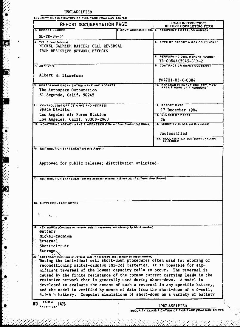
20. .ABSTRACT (Conllnua on ravaraa alda II naeaaaary and Idantlly by block ttumbar) -^During the individual cell short-down procedures often used for storing or reconditioning nickel-cadmium INi-Cd) batteries, it is possible for sig- nificant reversal of the lowest capacity cells to occur. The reversal is caused by the finite resistance of the common current-carrying leads in the resistive network that is generally used during short-down. A model is developed to evaluate the extent of such a reversal in any specific battery, and the model is verified by means of data from the short-down of a 4-cell, 3.5-A h battery. Computer simulations of short-down on a variety of battery
00 F0RM 1473 IF* CSIMI LE I UNCLASSIFIED
SECURITY CLASSIFICATION OF THIS PAGE (Whan Data Bntarad)
S- 1 - 1 - ■ - , ■ - - * - . . i . . - . - ^ . t .■ - - ..

UNCLASSIFIED »tCUWITV CLASSIFICATION Of THIS PA9t(Whm Wi Bwtgog 'it. KEY WORDS (ConUnutd)
20. ASSTRACT (Contlmud)
configurations indicate the desirability of controlling capacity imbalances arising from cell configuration and battery management, limiting variability in the short-down resistors, minimizing lead resistances, and optimizing lead configurations. (V u\ lv- r »«• w-
M ^ '^14 \0
llMCTiSSTFTPn SECURITY CLASSIFICATION OP TU» »ASKSkm »•#•
I
'»^>. i>. A- &.tifct>tv:v[-X\fcfcc^^

CONTENTS
I. INTRODUCTION 3
II. NETWORK ANALYSIS 7
III. EXPERIMENTAL RESULTS 9
IV. BATTERY SHORT-DOWN SIMULATIONS 15
V. CONCLUSIONS 25
DT1C ELECTE JAN 1 7 1985
B _ D
Accession For
NTIS GRA&I DTIC TAB Unannounced JustiJricm.ii.
By
Distribution/
^ a D
Availability Codes
Avail and/or ~ Special
ia4 . >%*- -'->*' ,*■\>y« A •.* -•- '.-- -■- ."' . ■
.•«•V»V«\V.v .■■

FIGURES
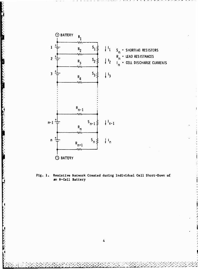
1. Resistive Network Created during Individual Cell Short-Down of an N-Cell Battery 4
2. Short-Down of a 4-Cell Battery; Cell 4 is Totally Discharged, and Cells 1 through 3 Have ~1-A h Capacity 11
3. Short-Down of a 4-Cell Battery; Cell 4 Discharge Started 1 hr Earlier than Did That of the Other Cells 12
4. Short-Down of a 4-Cell Battery; Cell 3 Discharge Started 1 hr Earlier than Did That of the Other Cells 13
5. Short-Down Simulation for a 4-Cell Battery, with 3.5 A h in Cells 1 through 3, and 2.5 A h in Cell 4 16
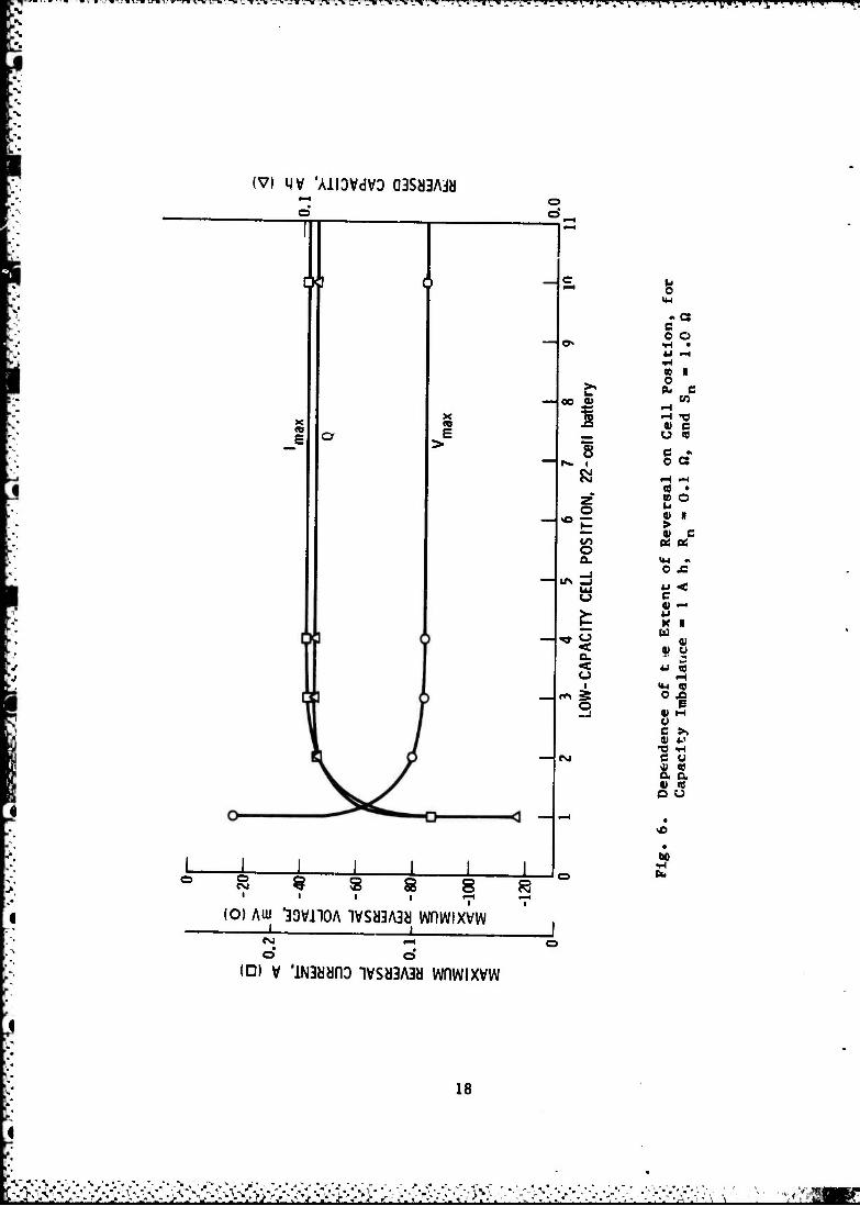
6. Dependence of the Extent of Reversal on Cell Posi- tion, for Capacity Imbalance - 1 A h, RJJ - 0.1 ft, and Sn « 1.0ft 18
7. Extent of Reversal as a Function of Lead Resistance for the Center Cell of an 11-Cell Battery, for Capac- ity Imbalance = 1 A h and Sn - 1.0 ft 19
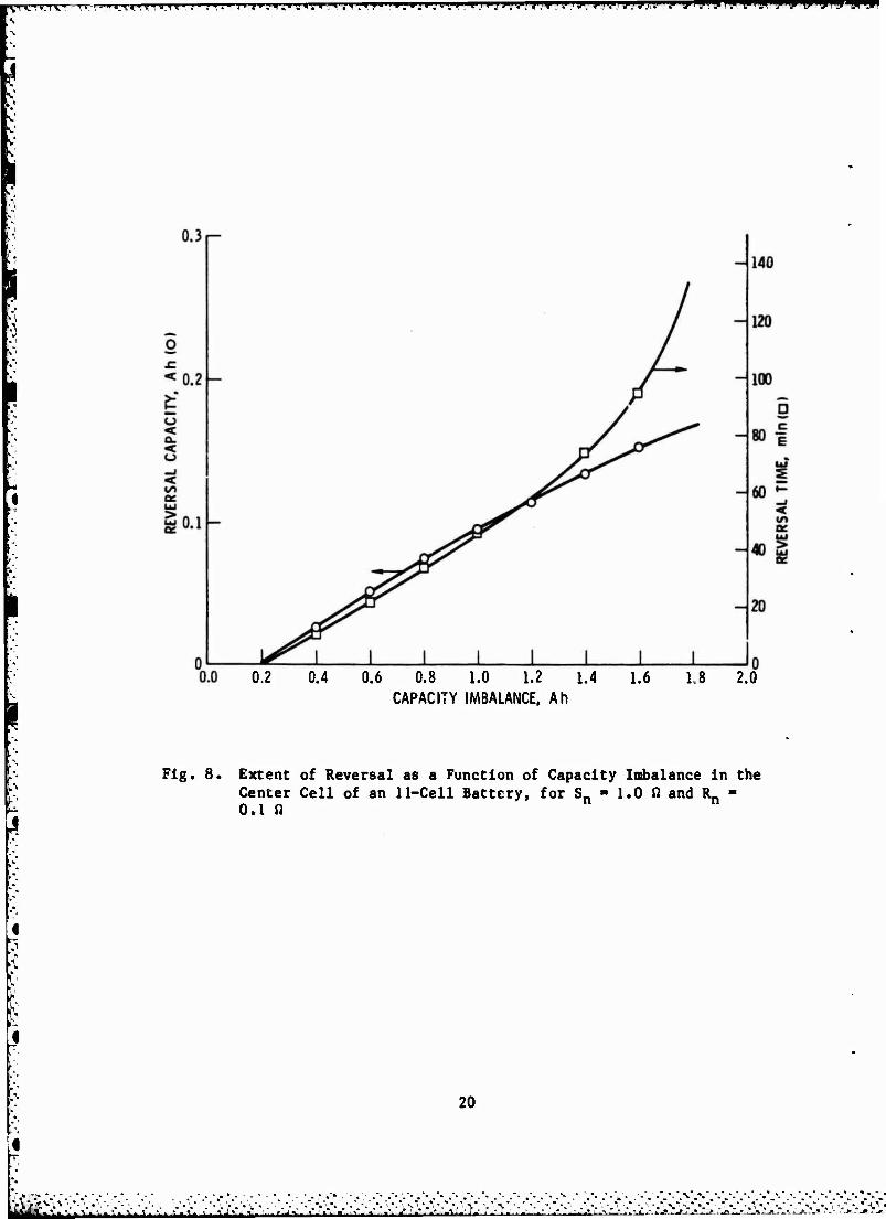
8. Extent of Reversal as a Function of Capacity Imbalance in the Center Cell of an 11-Cell Battery, for Sn - 1.0 ft and ^ - 0.1 ft 20
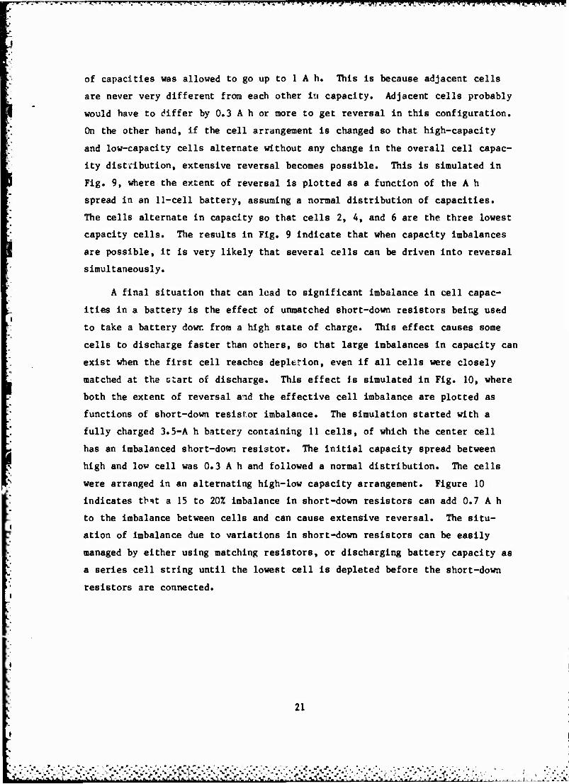
9. Extent of Reversal as a Function of Capacity Imbalance in an 11-Cell Battery Having Normal Capacity Distribu- tion (High/Low Alternation of Cells), for Sn - 1.0 ft and ^ - 0.1 ft 22
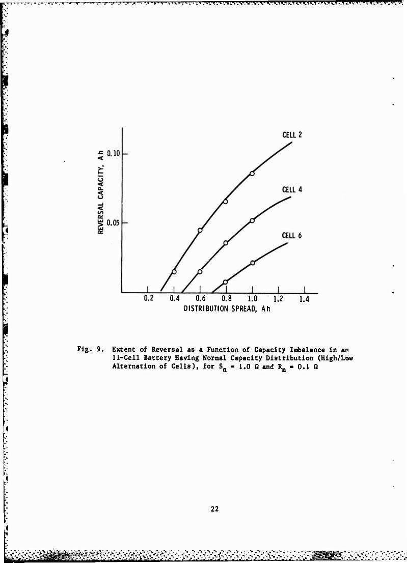
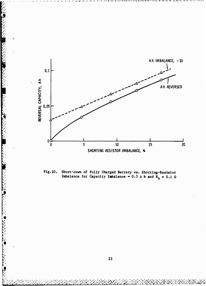
10. Short-Down of Fully Charged Battery vs. Snorting- Resistor Imbalance for Capacity Imbalance - 0.3 A h and \ - 0.1 ft 23
TABLE
1. Experimental Battery-Network Parameters 10
■
I. INTRODUCTION
Nickel-cadmium (Ni-Cd) battery cells are often stored during extended
periods of inactivity in a totally discharged state, usually with a shorting
connector across the terminals of each cell. Much evidence points to this
being the optimum storage mode, particularly at reduced temperature. In addi-
tion, a growing body of data also indicates that periodic total discharge of
individual cells in a battery is an extremely useful way of reconditioning and
balancing cell performance, and thus extending the operational life of a Ni-Cd
battery. For a battery of series-connected cells, the process of total dis-
charge must generally be done for each cell independently, so that the lower
capacity cells will not be series driven into reversal by the higher capacity
cells. A particularly simple way to accomplish an independent discharge for
each cell is merely to place a resistor (typically 18) across each cell and
allow the cell to discharge for an extended period of time. For batteries
this is often done by attaching a shorting resistor assembly to voltage
sensing wires at a battery connector.
Any realistic battery short-down procedure involving discharge of more
than one cell at a time cannot provide for totally independent discharge of
cells. This situation arises simply because of the finite resistance in the
connecting current-carrying leads common to adjacent cells. The short-down
procedure actually creates a resistive network in which coupling between
adjacent cells must always exist as long as any lead resistance is present, a»
indicated in Fig. 1.
Because of the coupling effects of lead resistances, there is a distinct
possibility that the lower capacity cells will be driven into reversal by the
higher capacity cells, even when individual resistors are connected across
each cell. The driving forces for such reversal should generally be minimized
by maintaining capacity balance, minimum lead resistance, optimized cell
configuration, and appropriate short-down procedures. In this report the
network of Fig. 1 is analyzed as a function of cell characteristics, lead
resistance, and shorting resistance. The extent of cell reversal that may
A ."• .
ril l^j^j^jjjj-jj-jjj|^j^j_^XilJlljlLLilj^ '•* '»■'■ «-: j.ijJj^»jLt^ ■• J : t ,o :■■:J iV,,
"-j" - m -.m
© BATTERY p Rl
-wv-
l'i
I'3
SHORTING RESISTORS
UEAD RESISTANCES
CELL DISCHARGE CURRENfS
l'n-1
0 BATTERY
Fig. 1. Resistive Network Created during Individual Cell Short-Down of an N-Cell Battery
i _«. -,, i. ■ , -. ....»..■..-.«. »-W-I. J.-J
- i ,",.-%-.».•»•,«. "i „ •»«. -, ■ _ . , ."V •." -." -." \" •-" •." -,"

-r -- _- u- j- ■ .- -•-»rir«->-.»-«-»'.l'nk'.,Tll^'.->V-li,>L>i.\ l"%1
realistically be expected if; calculated for typical battery short-down con-
figurations. Test data are also presented to support the model for a 4-cell
Ni-Cd battery consisting of 3.5-A h "D" cells. Finally, recommendations are
provided to indicate how to minimize the possibility of cell reversal during
individual cell short-down.
v ■.">.-*'> v"\-%." ■.-".-"". ■"".-" -\ -"•.-•.-"*.•-.-•.• v. % -"-.- -"• -"- -'• -"• -'• •"• ." .*•,"■ ."•>"•

fc-. '. - »
II. NETWORK ANALYSIS
For the network of Fig. 1, the cell currents In must be determined as a
function of the cell voltages Vn, the shorting resistances Sn, and the lead
resistances R_. For each cell n, the application of Kirchhoff's laws shows
that the current through the shorting resistor In must equal the cell current.
The voltage of each cell is equal to the sum of the voltage drops around each
loop, i.e.,
Vn - Vn + Rn^n " W + W1« " W (1)
which may be rearranged to
Vn - MSn + *n + W " ^+1^+1 " Vl** (2)
The relationships between voltage, current, and resistance are thus simply
reduced to the equation
R I - V (3)
where R is the n-by-n network resistance matrix with elements
ru - (si+ Ri+ W 6ij - Rj6i+i,j - Vw,j (A)
where 6.. is the delta function. The diagonal term in Eq. (4) represents the
discharge paths expected for ideal individual cell discharge. The off-
diagonal terms represent the coupling of each cell through the network to
other discharging cells. The current and voltage in Eq. (3) are both n-
element column vectors with elements In and Vn, respectively. Equation (3)
may be solved for the cell voltages VR if the currents 1^ are known, or the
currents may be determined if the voltages are known.
■-*»•»■■'•»' -"■■»■•.«•*-'-*».'■■.-.- - --•■■--■ i-. •.

V •. ^.~
III. EXPERIMENTAL RESULTS
To evaluate how the analysis of the previous section can be applied to
battery discharge, a 4-cell battery and resistance network were prepared hav-
ing the values given in Table 1. The cells were 3.5-A h Ni-Cd "D" cells. The
voltage and current of each cell was monitored as a function of time during
discharge through the resistors. The battery was typically charged for 16 h
at C/10 following at least a 16-h short-down.
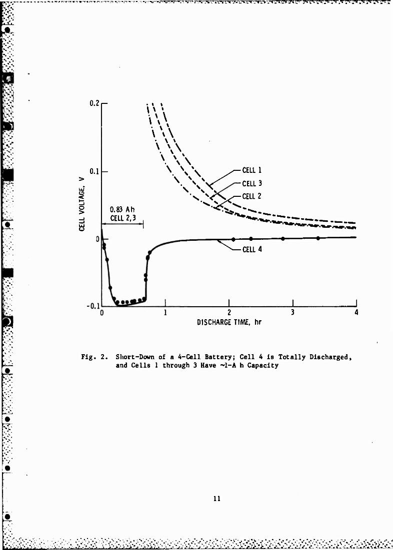
The first test involved charging cells 1 through 3 only, discharging
these three cells for 2.5 h at 1 A, then resistively shorting down all four
cells using the network defined in Table 1. The observed voltage behavior for
the four cells is indicated in Fig. 2, where the points indicate the voltage
calculated from Eq. (3) and the lines Indicate the experimentally measured
voltages. Cell 4, which is totally discharged, remains in reversal for about
2.5 h. The reversal current depends on the voltage of the other cells, but
was as high as 94 mA (C/37) early in the reversal. The good agreement between
the experimental data and the calculated points in Fig. 2 indicates that the
network model of Fig. 1 can accurately describe the behavior of battery cells
during individual cell short-down.
The second test inv >lved connecting the shorting resistor to cell 4, 1 h
before shorting down the other cells, thus creating about a 1-A h lower capac-
ity in cell 4. As indicated in Fig. 3, cell 4 was still driven into reversal
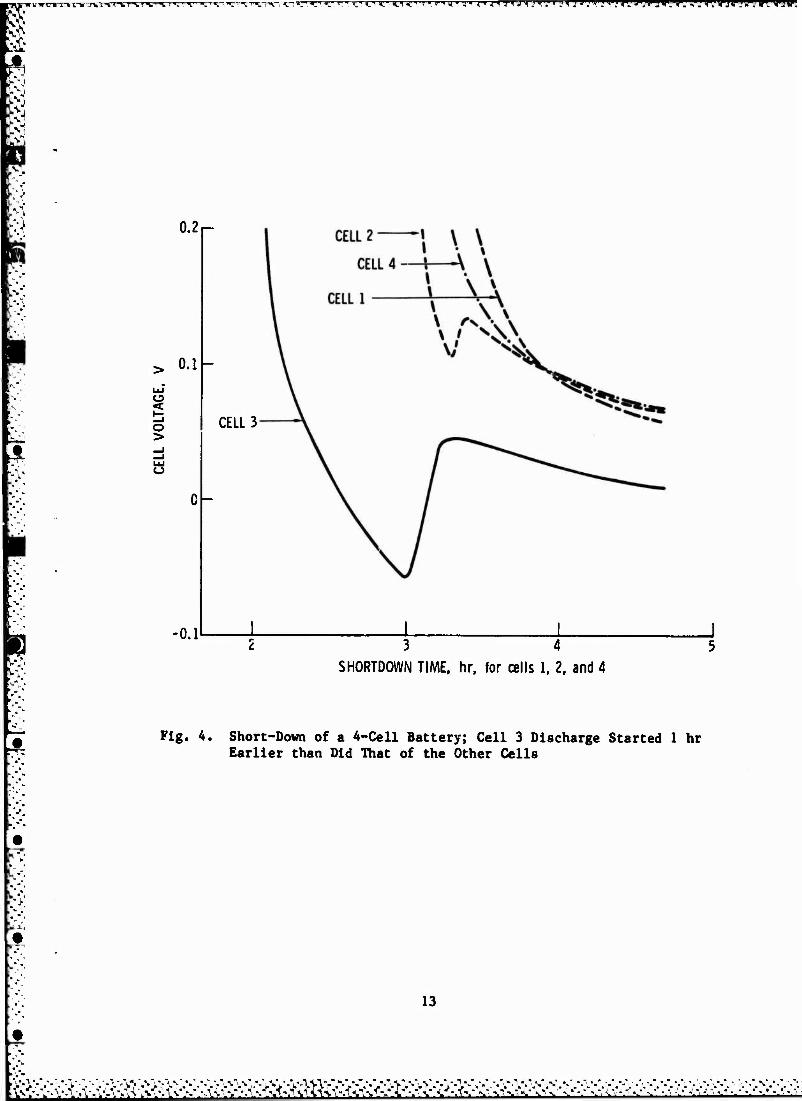
for about 12 min with a maximum reversal rate of 92 mA. The third test was
similar to the second test except that short-down was begun 1 h earlier on
cell 3 rather than on cell 4. The results are Indicated in Fig. 4. The
reversal rate was 172 mA, about twice that of the previous test, presumably
because during most of the reversal period the cells on each side of cell 3
had high voltages. In the third test tht cell was in reversal for 32 min.
These results suggest that during short-down the end cells in a series string
hive a ruch more benign environment with regard to reversal.
L-1~L 1-1..- - ■ -1 ■ 1 - - «-«-«-«-- .«-.«■» ±^L. _•:■:.: :-:.-o,^>:>>^ -.•> :■>:.-. -.>•

Table 1. Experimental Battery Network Parameters for 4 Cells Connected In Series (3.5 A h)
Lead Resistance, ft Shorting Resistance, ft
Rx - 0.0721 Sj - 1.045
R2 - 0.0786 S2 - 0.940
R3 - 0.0878 S3 - 0.991
R4 » 0.0942 SA - 0.974
R5 - 0.0879
10
i-u■«imrvuxwimjv\mvr%wuHD'i.'J■ L>wmnnyHUi Jf».VW I»'".Iff 1if i'i*1^1»!*M*^ J
0.2 r-
0.1
<
o > 0.83 Ah
CELL 2,3
V\ \ \\
\ w W
CELLI
CELL 3
CELL 2
**,
» «
•CELL 4
2 3
DISCHARGE TIME, hr
Fig. 2. Short-Down of a 4-Cell Battery; Cell A Is Totally Discharged, and Cells 1 through 3 Have ~1-A h Capacity
11
'••":."::• .\ >•_/:-> ;± v •.-.•>■•-• .■- .- Vi ■•i^.V- Ü ■■«>»>>>•■•■>'
. -. - • ö\ • - l - r<\V - - '

r^r> »>■»>■> ^ ■j^,v,'^«A^r^y^T^n. iv.VA TT\^vv^ ^,t!,y* ff^wwgy
0.2
0.1
to < o >
8
-0.1
CELL 4
1.01 Ah
2 3 4
SHORTDOWN TIME, hr, for cells 1 through 3
Fig. 3. Short-Down of a 4-Cell Battery; Cell 4 Discharge Started 1 hr Earlier than Did That of the Other Cells
12
^■-'•■i-'-r ■-■ V '-P ■■■• ' '• .H • i> - * - • ;*:•,•:• - . - • - U ,'
»'* -"- WV/:.m.•J.'.-^.'ji".^'.-.;".«-»>.->>V: »VV-.V-UY--.-.-. ,■ V "-• ".•'.' .• ,*> •>\S *
rr,c. v. ^,--, .. PTTTT' <''.n. rrj'j.".' js j i,yy!-m!r:,-rm}v?v,."iri-r,iv?rjv*im:wjiKv'.
0.2
0.1
o >
-0.1
CELL 3
0-
3 4
SHORTDOWN TIME, hr, for cells 1, 2, and 4
Fig. 4. Short-Down of a 4-Cell Battery; Cell 3 Discharge Started 1 hr Earlier than Did That of the Other Cells
13
•»!, ".
r-w--.,---S-^T-^-*irrv-TTr-%rrr^-Tr*-VT~ZT*r™ ■■■■iyi\ ■-^ri-'V^ -~tfv fg-y ■■'' V V «. '"% '■ V'-." "■. 'T'- ' ■■ '■.»: ■ ■■' \ '.'-11. *.' 'A '.'."■.■■■.•: pi P
IV. BATTERY SHORT-DOWN SIMULATIONS
Tha short-down of a battery containing n cells was simulated by a com-
puter model. The inputs to this model consisted of shorting resistances, lead
resistances, the capacity in each cell, and a current-voltage relationship as
a function of residual capacity discharged from the depleted cell.
The current-voltage relationship that was used in the simulations was
derived from short-down data for 3.5-A h cells having 1-0 short-down resis-
tors, and is meant to provide only a representative current/voltage relation-
ship during short-down. Each cell was assumed to have a constant voltage of
1.15 V until its capacity was depleted, after which the voltage decreased
linearly to 0.2 V during the discharge of an additional 0.04 A h. Thereafter
each cell was assumed to have a voltage given by
V = 0.317 x 10"5Q - AK1.228 lO"1,226*1) (5)
where Q is residual capacity discharged in A h, and AI is any discharge cur-
rent in excess of that anticipated from the diagonal terms in Eqs. (3) and
(4). Equation (5) was obtained empirically by fitting the voltage of one cell
during short-down. When the voltage is negative, a limit of Vn » -0.06
log(I/0.00014) is used to give a reasonable asymptotic dependence for hydrogen
evolution. While this model is only approximate, it provides a reasonable
empirical representation of the short-down behavior with 1-fl resistors, which
can be used for evaluating trends in the short-down behavior.
The first computer simulation was for a 4-cell battery using the short-
down parameters of Table 1: 3.5 A h of capacity for cells 1 through 3 and
2.5 A h for cell 4. The trends in the simulation should therefore be directly
comparable to the data in Fig. i. The results of the simulation., indicated in
Fig. 5, clearly show the same features as the data in Fig. 3.
The second computer simulation was done for a 22-cell battery where 1
cell was assumed to have 1 A h less capacity than the other 21 cells, and the
position cf the low-capacity cell was varied from one end to the middle of the
15
■'■>**> -•*'--'V-•'•-• -- 's '-• •-• ■• '-- '> "'-• *■'-*-■-%•'/-"••- ■■''*-■'- ■*■ -•/-'■ •'■ •". • • •'-' ■

--iP-^r-fc-^r-;^-^r^;^"i,'^"%'-M^'.'.'V,'.".- V gl HI" VI rT1' T! *TTTTTTTTT» Tl »T"' S V7vcTTTCT^T^TT^CTWWl*W gCT?W?^ -*■'
0.2 i—
o
o >
0.1
■0.1
CELLI
CELL 2
^X /-CELL 3
i l< V I • \ \\ I: •* ^-
3 4 5 SHORTDOWN TIME, hr, for cells 1 through 3
Fig. 5. Short-Down Simulation for a 4-Cell Battery, with 3.5 A h in Cells 1 through 3, and 2.5 A h in Cell 4
16
.as v v\• w, s\ ••v.uis.

IVVi iTlir n n <ii' .-'THI j'Tm «'* T .'« m *T'". rr.Tj' jr,7i'jr-i !'»■■ »■:"C'v.'uvr,vJ—;g*."i*.' TVT' ,'T' I'.'yTTT?'- ."^yr.
cell string. All shorting resistors were 1 ft and all lead resistances were
0.1 ft. The results of this simulation, presented in Fig. 6, clearly show
that the end cell should be subject to considerably less reversal than cells
of equal capacity situated away from either end of the cell string.
A third simulation was done to determine the effect of varying the lead
resistance on the cell reversal. An 11-cell battery was simulated, with the
A h in reversal during snort-down plotted as a function of lead resistance in
Fig. 7. The center cell was assigned 1 A h less capacity than the other
cells, so it is the cell being reversed in Fig. 7. All short-down resistances
were 1.0 ft. From the results in Fig. 7, approximately 25 mft of lead resistance
are required before reversal occurs under these conditions of simulation. The
amount of reversal increases in a nearly linear fashion as the lead resistance
is increased relative to the shorting resistance.
It is expected that the amount of cell reversal should increase as capac-
ity imbalance increases. In Fig. 8 a fourth simulation is presented in which
the capacity imbalance is varied and both the capacity and the time in rever-
sal are plotted. This simulation is for an 11-cell battery whose center cell
is low in capacity; shorting resistors are 1.0 ft, and lead resistors are
0.1 ft. Both capacity and time in reversal increase with increasing capacity
imbalance. However, if the imbalance is near 2 A h or higher, the low cell
will stay in reversal long after the other cells are depleted, since it has
been taken down far enough in capacity that even the low residual voltages
present for the other cells can hold the low cell in reversal. The data in
Fig. 8 clearly indicate the need to avoid conditions that can lead to large
imbalances in capacity.
Capacity imbalances between the cells of a battery are generally con-
trolled to less than 52 of the total capacity by cell matching procedures.
However, extended periods of open-circuit stand, cycling, or other environ-
mental considerations may temporarily create greater imbalances. If a normal
distribution of cell capacities is assumed for an 11-cell battery, and these
cells are arranged in order of Increasing capacity in the battery, it was not
possible to reverse any cells in a computer simulation where the total spread
17
w .1.-.:-. ■ ■ -'I.N.
rmrvrrwTTWVTxrrTrVTVW. mrww 'A'.i'.Ti^'Ar. 7t '^ ',\ '.S' ^ ':.' ',■! 'Il '.T ',■• l;-' 'T.' '.'' I"' ^ 'A I l"U'^ [ .>,a\ *V*\* '. *^ul. <"!,"H"*i' '\\
(V) gv 'AllDVdVD G3SM3AJM
W
X to E
f
1
00 «>
o CM 9 s a
s
o
«/» o a.
a. <
o
C\J
S R
(O) AUi lOVllOA 1VSH3A3H WflWIXVW I I
© o (0) V 'lN3U»nD "1VSH3A3H WflWIXVW
u o <u
•t a c o o
•H • 4J •■H
•H 09 II 0 a- c
CO iH •H •o V c u «9
c « o a i-l ^H
«0 • 09 o U V II > V e
«6 tc ■W * 0 j=
4J < c fl> t-H
4J K ii W
a» a> u *-
4J « i-i
14-1 «a 0 X)
E 0) M u c >■» V 4.1
•o •H c U <u « a a 0) « o u
bo «i-i fa
18
•>'»>•• -• -• . J -■ - ■ -• . , 7 : , , V . . . ... - - i22L ;,', v.

■ M >»—if '^'»SJT v*vn ramnrai • gTwgT?TPTt^f^r-.,*^^pnewwiwwptwwwyfigwiwwi^^w^WfffW^Wf^
0.1 0.2 HAD RESISTANCES, ß
0.3
Ä
Fig. 7. Extent of Reversal as a Function of Lead Resistance for the Center Cell of an 11-Cell Battery, for Capacity Imbalance « 1 A h and Sn - 1.0 SI
19
1$$^^ ■P.- v v V V V \* V v >
*. T;..,.n f,.,..^l-|,«,,..T.^...1 i.v ....,..,;! jii.y n i ■ j ^IJIII pay ii»! *: •?!!*.'WW.klmW9FW WVIZVW^-'^W^n*
0,2 0.4 0.6 0.8 1.0 1.2 1.4 CAPACITY IMBALANCE, Ah
1.6 1,8 2.0
Fig. 8. Extent of Reversal as a Function of Capacity Imbalance in the Center Cell of an 11-Cell Battery, for S » 1.0 fl and R» 0.1 a
20
-•^ *. -. . -. . ■. ..., . *. i..... * j»- «^ :,.:^_
~r. m -, ; . .-. '.-w~—-im . " u_. p. rm w «,■";'. *;"•■»Twyp^ '■ ' ii»j«T,«"twi<»i^|ii^-yy {;»"■■ p^'-iy pypypi) 111 ju»pjiijjpj|jiy«pj lJi.".*'^"J?\y>'Vy;'^^W>«^^^»yyyy
of capacities was allowed to go up to 1 A h. This is because adjacent cells
are never very different from each other In capacity. Adjacent cells probably
would have to differ by 0.3 A h or more to get reversal in this configuration.
On the other hand, if the cell arrangement is changed so that high-capacity
and low-capacity cells alternate without any change in the overall cell capac-
ity distribution, extensive reversal becomes possible. This is simulated in
Fig. 9, where the extent of reversal is plotted as a function of the A h
spread in an 11-cell battery, assuming a normal distribution of capacities.
The cells alternate in capacity so that cells 2, 4, and 6 are the three lowest
capacity cells. The results in Fig. 9 indicate that when capacity imbalances
are possible, it is very likely that several cells can be driven into reversal
simultaneously.
A final situation that can lead to significant imbalance in cell capac-
ities in a battery is the effect of unmatched short-down resistors being used
to take a battery down from a high state of charge. This effect causes some
cells to discharge faster than others, so that large imbalances in capacity can
exist when the first cell reaches depletion, even if all cells were closely
matched at the start of discharge. This effect is simulated in Fig. 10, where
both the extent of reversal and the effective cell imbalance are plotted as
functions of short-down resistor imbalance. The simulation started with a
fully charged 3.5-A h battery containing 11 cells, of which the center cell
has an imbalanced short-down resistor. The initial capacity spread between
high and low cell was 0.3 A h and followed a normal distribution. The cells
were arranged in an alternating high-low capacity arrangement. Figure 10
indicates tbit a 15 to 20% imbalance in short-down resistors can add 0.7 A h
to the imbalance between cells and can cause extensive reversal. The situ-
ation of imbalance due to variations in short-down resistors can be easily
managed by either using matching resistors, or discharging battery capacity as
a series cell string until the lowest cell is depleted before the short-down
resistors are connected.
21
rwj ^^~m~^ ^7T T-T-y^-.-."/-:-? -_■-*-'■ TTTW TTf»TT^i .'V.'M'.'V '.■VlATWViWm'HHH ^'1^.T>'*^*"4.' WT^ff^^B^ff^y
0.4 0.6 0.8 1.0 1.2
DISTRIBUTION SPREAD, Ah 1.4
Fig. 9. Extent of Reversal as a Function of Capacity Imbalance in an 11-Cell Battery Having Normal Capacity Distribution (High/Low Alternation of Cells), for SR > 1,0 II and R- 0.1 0
22
-„afttifr ■^L-'^-iy* '■*?>: V>J.>JI>J%J-"».. ;
-- — ■-- ■-•—*- -r -r■-■--■■/ - ■ .-•....... . .—IJI.I. ,
k-»\r»i.-w >.-.<--.'. HM".1 \- ntimm c"
Ah IMBALANCE, -10
Ah REVERSED
5 10
SHORTING RESISTOR IMBALANCE. %
20
Fig.10. Short-Down of Fully Charged Battery vs. Snorting-Resistor Imbalance for Capacity Imbalance - 0.3 A h and R_ - 0.1 fi
23
c /. ■-. -•-■-■-•■
• rj« *> • ■.".- •> r -'
^_M_- •_-.*.

•- -• -W -- LT. ir»i ->r-- ->"^- •^•f :~v.'"wj« T7»7 « V" *
V. CONCLUSIONS
The results presented here indicate that significant reversal of the
lowest capacity cells can result from individual cell short-down of a Ni-Cd
battery. A model has been presented that provides a straightforward way to
evaluate the risk of cell reversal for a particular battery or a particular
short-down procedure. The consequences of cell reversal are likely to be
(1) some hydrogen evolution, although not enough to overpressurize the cell;
and (2) significant Cd reduction at the Ni electrode, possible leading to Cd
dendrite short-circuits. Such short-circuits, if formed, will be oxidized
during recharge and are not expected to compromise performance.
This report suggests a number of points that are important in minimizing
the possibility of cell reversal, as follows:
1. Minimize capacity imbalances that may arise from uncontrolled bat- tery handling or storage. This is particularly important during integration and test procedures.
2. Do not discharge battery capacity from a high state of charge by using individual cell short-down. Discharge the battery as a series string of cells until the lowest capacity cell is depleted, then apply short-down resistors to individual cells.
3. Use 1%-tolerance resistors for short-down.
4. Minimize lead resistance relative to the resistance of the short- down resistors. Lead resistance includes that of leads internal to the battery assembly, plus that of any cabling used to connect the battery to a breakout box where the short-down resistors are attached. The ultimate solution to minimize lead resistance is to attach the short-down resistors at the cell terminals, or to attach separate leads at each cell terminal.
5. The arrangement of cells within a battery Is critical. The optimum arrangement for minimizing the possibility of cell reversal is to order the series string of cell« in terms of capacity, from high at one end to low at the other end. This procedure makes it difficult to reverse any cell in the string . iring short-down as long as the spread in cell capacities does not increase significantly beyond the initial spread typically allowed In Ni-Cd batteries.
25
.^.'■■^■■■•■.V.
••V- ,•-•■
■Mft

„..,....- ■*, .. ..,, - j.ry^r?--T-jrryr.w-gr-jr-^yryjT>->-J--»r»v»r»r*rvr-1 tTTTCTt^v:11'TOT<1V.HV.'-■ *"**"*,""7!
4 v" 6. The end cells in the series-connected string are always less subject to reverse discharge during individual cell short-down than the other cells in the battery.
26
.">■..■> k"-y) .>." •1>WY«

LABORATORY OPERATIONS
The Laboratory Operation* of The Aeroapace Corporation la conducting
experimental and theoretical Investigations necessary for the evaluation and
application of scientific advances to new military apace systems. Versatility
and flexibility have been developed to a high degree by the laboratory person-
nel In dealing with the aany problens encountered In the nation's rapidly
developing space systems. Expertise In the latest scientific developments is
vital to the accomplish«*«' ''■ casks related to these problens. The labora-
tories that contribute to this research are:
A»-.upny3lcs Laboratory: Launch vehicle and reentry fluid Mechanics, heat transfer and flight dynamics; chealcal and electric propulsion, propellent chemistry, environmental hazards, trace detection; spacecraft structural mechanics, contamination, thermal and structural control; high temperature tneraoaechanlcs, gas kinetics and radiation; cw and pulsed laser development Including chealcal kinetics, spectroscopy, optical resonators, beam control, atmospheric propagation, laser effects and counterseasures.
Chemistry and Physics Laboratory: Atmospheric chealcal reactions, atmo- spheric optics, light scattering, state-specific chealcal reactions and radia- tion transport in rocket plumes, applied laser spectroscopy, laser chemistry, laser optoelectronics, solar cell physics, battery electrochemistry, space vacuum and radiation effecta on materials, lubrication and surface phenomena, thermionic emission, photosensitive materials and detectors, atoalc frequency standards, and environmental chemistry.
Electronics Research Laboratory: Microelectronics, GaAs low noise and power devices, semiconductor lasers, electromagnetic and optical propagation phenomena, quantum electronics, laser communications, lldar, and electro- optics; communication sciences, applied electronics, semiconductor crystal and device physics, radlometrlc imaging; millimeter wave, microwave technology, and RF systems research.
Information Sciences Research Office: Program verification, program translation, performance-sensitive systea design, distributed architectures for spacehor . coaputers, fault-tolerant computer aysteas, artificial Intel- ligence and microelectronics applications.
Materials Sciences Laboratory: Development of new materials: aetal matrix coapoaltes, polymers, and new form* of carbon; nondestructive evalua- tion, component failure analysis and reliability; fracture aschanlcs and stress corrosion; analysis and evaluation of material* at cryogenic and elevated teaperaturea a* well aa in «pace and eneay-lnduced environment*.
Space Sciences Laboratory: Magnetospherlc, auroral and eosalc ray phys- ics, wave-particle lnteractiona, aagnetospherlc plaaaa waves; atmospheric and Ionospheric physic*, density and composition of the upper atmosphere, remote sensing using atmospheric radiation; solar physic«. Infrared aatronoay, Infrared signature analyil«; effects of solar activity, aagnetle storms snd nuclear explosions on the earth's atmosphere, Ionosphere and magnetosphere; effecta of electromagnetic and partlculate radiations on space aystems; space Instrumentation.
P. ■«a — " ■