ni 5622 calibration procedure - national instruments · ni 5622 calibration procedure 2 ni.com...
TRANSCRIPT

CALIBRATION PROCEDURE
NI 5622This document contains instructions for writing an external calibration procedure for National Instruments PXIe-5622 digitizers. This calibration procedure is intended for metrology labs. For more information about calibration, visit ni.com/calibration.
ContentsConventions ............................................................................................ 2Software Requirements ........................................................................... 3Documentation Requirements................................................................. 4Password ................................................................................................. 5Calibration Interval ................................................................................. 5
External Calibration ......................................................................... 5Self-Calibration................................................................................ 5
Test Equipment ....................................................................................... 5Test Conditions ....................................................................................... 7Calibration Procedures ............................................................................ 8
Initial Setup...................................................................................... 9Self-Calibration................................................................................ 9
MAX......................................................................................... 9NI-SCOPE SFP......................................................................... 9NI-SCOPE ................................................................................ 10
Test Equipment Adjustment ............................................................ 11Zero Power Meter ..................................................................... 11Power Splitter Amplitude Imbalance Correction ..................... 11
Verification ...................................................................................... 14Absolute Amplitude Accuracy ................................................. 14Bandpass Amplitude Flatness................................................... 21Timing Accuracy ...................................................................... 30SSB Phase Noise ...................................................................... 34Average Noise Density ............................................................. 42
Adjustment....................................................................................... 46Appendix A: Calibration Utilities ........................................................... 51
MAX ................................................................................................ 51NI-SCOPE ....................................................................................... 52
Where to Go for Support......................................................................... 52

NI 5622 Calibration Procedure 2 ni.com
ConventionsThe following conventions are used in this document:
» The » symbol leads you through nested menu items and dialog box options to a final action. The sequence Options»Settings»General directs you to pull down the Options menu, select the Settings item, and select General from the last dialog box.
This icon denotes a note, which alerts you to important information.
This icon denotes a caution, which advises you of precautions to take to avoid injury, data loss, or a system crash.
bold Bold text denotes items that you must select or click in the software, such as menu items and dialog box options. Bold text also denotes parameter names.
italic Italic text denotes variables, emphasis, a cross-reference, or an introduction to a key concept. Italic text also denotes text that is a placeholder for a word or value that you must supply.
monospace Text in this font denotes text or characters that you should enter from the keyboard, sections of code, programming examples, and syntax examples. This font is also used for the proper names of disk drives, paths, directories, programs, subprograms, subroutines, device names, functions, operations, variables, filenames, and extensions.
Platform Text in this font denotes a specific platform and indicates that the text following it applies only to that platform.

© National Instruments Corporation 3 NI 5622 Calibration Procedure
Software RequirementsCalibrating the NI 5622 requires installing the following software on the calibration system.
You can download NI-SCOPE from the National Instruments web site at ni.com/updates. NI-SCOPE supports programming the Self-Calibration and Verification sections in a number of programming languages; however, only LabVIEW and C are supported for the Adjustment section.
NI-SCOPE includes all the functions and attributes necessary for calibrating the NI 5622. LabVIEW support is installed in niScopeCal.llb, and all calibration functions appear in the function palette. For LabWindows™/CVI™, the NI-SCOPE function panel niScopeCal.fp provides further help on the functions available in CVI. Refer to Table 2 for installed file locations.
Calibration functions are LabVIEW VIs or C function calls in the NI-SCOPE driver. The C function calls are valid for any compiler capable of calling a 32-bit DLL. Many of the functions use constants defined in the niScopeCal.h file. To use these constants in C, you must include niScopeCal.h in your code when you write the calibration procedure.
For more information on the calibration VIs and functions, refer to the NI-SCOPE LabVIEW Reference Help or the NI-SCOPE Function Reference Help. These references can be found in the NI High-Speed Digitizers Help. Refer to the NI-SCOPE Readme for the installed locations of these documents.
Table 1. Required Software Specifications for NI 5622 Calibration
LabVIEW LabWindows/CVI and C/C++
NI-SCOPE 3.5 or later NI-SCOPE 3.5 or later
NI LabVIEW Digital Filter Design Toolkit 8.2.1 or later
NI Modulation Toolkit for LabWindows/CVI 2.0 or later
NI Modulation Toolkit for LabVIEW 3.0 or later
—

NI 5622 Calibration Procedure 4 ni.com
Documentation RequirementsYou may find the following documentation helpful as you write your calibration procedure:
• NI High-Speed Digitizers Getting Started Guide
• NI High-Speed Digitizers Help
– NI-SCOPE LabVIEW Reference Help (NI-SCOPE VIs and NI-SCOPE Properties)
– NI-SCOPE Function Reference Help
• NI PXIe-5622 Specifications
These documents are installed with NI-SCOPE. You can also download the latest versions from ni.com/manuals.
Table 2. Calibration File Locations after Installing NI-SCOPE
File Name and Location Description
IVI\Bin\niscope_32.dll NI-SCOPE driver containing the entire NI-SCOPE API, including calibration functions
IVI\Lib\msc\niscope.lib NI-SCOPE library for Microsoft C containing the entire NI-SCOPE API, including calibration functions
<LabVIEW>\examples\instr\niScope Directory of LabVIEW NI-SCOPE example VIs, including self-calibration.
<LabVIEW>\instr.lib\niScope\Calibrate\niScopeCal.llb
LabVIEW VI library containing VIs for calling the NI-SCOPE calibration API.
IVI\Drivers\niScope\niScopeCal.fp CVI function panel file that includes external calibration function prototypes and information about using NI-SCOPE in the CVI environment.
IVI\Include\niScopeCal.h Calibration header file, which you must include in any C program accessing calibration functions. This file automatically includes niScope.h, which defines the rest of the NI-SCOPE interface.
IVI\Drivers\niScope\Examples Directory of NI-SCOPE examples for CVI, C, Visual C++, and Visual Basic.

© National Instruments Corporation 5 NI 5622 Calibration Procedure
PasswordA password is required to open an external calibration session. If the password has not been changed since manufacturing, the password is NI.
Calibration Interval
External CalibrationThe measurement accuracy requirements of your application determine how often you should externally calibrate the NI 5622. NI recommends that you perform a complete external calibration at least once every year. You can shorten this interval based on the accuracy demands of your application.
Self-CalibrationYou can perform self-calibration whenever necessary to compensate for environmental changes.
Caution Although you can repeatedly self-calibrate, self-calibrating the NI 5622 more than a few times a day may cause excessive wear on the relays over time.
Test EquipmentTable 3 lists the equipment required for externally calibrating the NI 5622. If you do not have the recommended instruments, use these specifications to select a substitute calibration standard.

NI 5622 Calibration Procedure 6 ni.com
Table 3. Required Equipment Specifications for NI 5622 External Calibration
Required Equipment
Recommended Equipment
Calibration Procedure Specification
Signal Generator
Rohde and Schwarz SMA-B103 with SMA-B22 option, enhanced phase noise performance
SSB Phase Noise Carrier
Frequency
Carrier Offset
100 Hz 1 kHz 10 kHz
53 MHz –108 dBc/Hz
–146 dBc/Hz
–158 dBc/Hz
187 MHz –98dBc/Hz
–135 dBc/Hz
–148 dBc/Hz
Bandpass Amplitude Flatness,Absolute Amplitude Accuracy, SSB Phase Noise, Timing Accuracy, Adjustment
Frequency Range: 900 kHz to 820 MHz
Power Measurement Level Setting Range: –4 dBm to 10 dBm
Timing Accuracy, Adjustment
±0.1 ppm frequency accuracy
Power Meter
Rohde and Schwarz NRP-Z91 with NRP-Z4 USB adapter
Absolute Amplitude Accuracy,Bandpass Amplitude Flatness, Adjustment
Frequency Range: 900 kHz to 820 MHz
Power Measurement Range: –4 dBm to 3 dBm
Maximum VSWR: 1.11 (23 ±5 °C)
Absolute Power Measurement Uncertainty: 0.1 dB (23 ±5 °C)
Relative Power Measurement Uncertainty: 0.05 dB (23 ±5 °C)

© National Instruments Corporation 7 NI 5622 Calibration Procedure
Test ConditionsFollow these guidelines to optimize the connections and the environment during calibration:
• Keep cables as short as possible. Long cables act as antennae, picking up noise that can affect measurements.
• Verify that all connections, including front panel connections, are secure.
SMA Cable Mini-Circuits CBL-1.5FT-SMSM+
Bandpass Amplitude Flatness, Absolute Amplitude Accuracy, SSB Phase Noise, Timing Accuracy, Adjustment
50 Ω, Maximum VSWR: 1.20
Frequency Range: 900 kHz to 820 MHz
Power Measurement Range: –4 dBm to 3 dBm
Relative Shielding: –100 dB
Attenuator Mini-Circuits VAT-3+
SSB Phase Noise
Frequency Range: 900 kHz to 820 MHz
Minimum Power (W): 10 mW
Maximum VSWR: 1.20
Nominal Attenuation: 3 dB
SMA Termination
Mini-Circuits ANNE-50+
Average Noise Density
50 Ω
Power Splitter
Weinschel WA1507R
Absolute Amplitude Accuracy,Bandpass Amplitude Flatness,Adjustment
Frequency Range: 900 kHz to 820 MHz
Input Power Range: –4 dBm to 3 dBm
Maximum VSWR (Output ports): 1.15
Maximum Amplitude Tracking: 0.15 dBm
Table 3. Required Equipment Specifications for NI 5622 External Calibration (Continued)
Required Equipment
Recommended Equipment
Calibration Procedure Specification

NI 5622 Calibration Procedure 8 ni.com
• Ensure that the PXIe chassis fan speed is set to HIGH, that the fan filters are clean, and that the empty slots contain filler panels. For more information, refer to the Maintain Forced-Air Cooling Note to Users, available at ni.com/manuals.
• Keep relative humidity between 10% and 90% noncondensing, or consult the NI PXIe-5622 Specifications for the optimum relative humidity.
• Maintain an ambient temperature of 23 ±5 °C.
• Allow a warm-up time of at least 15 minutes after the NI-SCOPE driver is loaded. Unless manually disabled, NI-SCOPE automatically loads with the operating system and enables the device. The warm-up time ensures that the measurement circuitry of the digitizer is at a stable operating temperature.
• Plug the PXI Express chassis and the test equipment into the same power strip to avoid ground loops.
Calibration ProceduresThe calibration process includes the following steps.
1. Initial Setup—Install the device and configure it in Measurement & Automation Explorer (MAX).
Note Allow a 15-minute warm-up time before beginning self-calibration.
2. Self-Calibration—Adjust the self-calibration constants of the device.
3. Test Equipment Adjustment—Zero the power meter and calculate power splitter imbalance.
4. Verification—Verify the existing operation of the device. This step confirms whether the device is operating within its specified range prior to calibration.
5. Adjustment—Perform an external adjustment of the device that adjusts the calibration constants with respect to a known voltage source. The adjustment procedure automatically stores the calibration date on the EEPROM to allow traceability.
6. Reverification—Repeat the verification procedure to ensure that the device is operating within its specifications after adjustment.
These steps are described in more detail in the following sections.

© National Instruments Corporation 9 NI 5622 Calibration Procedure
Initial SetupRefer to the NI High-Speed Digitizers Getting Started Guide for information about how to install the software and hardware and how to configure the device in MAX.
Self-CalibrationThe NI 5622 includes precise internal circuits and references used during self-calibration to adjust for time and temperature drift.
Note Allow a 15 minute warm-up period before you begin self-calibration.
Note Always self-calibrate the digitizer before you perform verification. NI-SCOPE includes self-calibration example programs for LabVIEW, CVI, and Microsoft Visual C.
You can initiate self-calibration using the following methods:
• MAX
• NI-SCOPE Soft Front Panel (SFP)
• NI-SCOPE
MAXTo initiate self-calibration from MAX, complete the following steps:
1. Disconnect or disable any AC inputs to the digitizer.
2. Launch MAX.
3. Expand My System»Devices and Interfaces»PXI System.
4. Select the device that you want to calibrate.
5. Initiate self-calibration using one of the following methods:
• Click Self-Calibrate in the upper right corner of MAX.
• Right-click the name of the device in the MAX configuration tree and select Self-Calibrate from the drop-down menu.
NI-SCOPE SFPTo initiate self-calibration from the NI-SCOPE SFP, complete the following steps:
1. Disconnect or disable any AC inputs to the digitizer.
2. Launch the NI-SCOPE SFP, which is available at Start»All Programs»National Instruments»NI-SCOPE»SCOPE Soft Front Panel.
3. Select the device you want to calibrate using the Device Configuration dialog box by selecting Edit»Device Configuration.
NI 5622 Calibration Procedure 10 ni.com
4. Launch the Calibration dialog box by selecting Utility»Self Calibration.
5. Click OK to begin self-calibration.
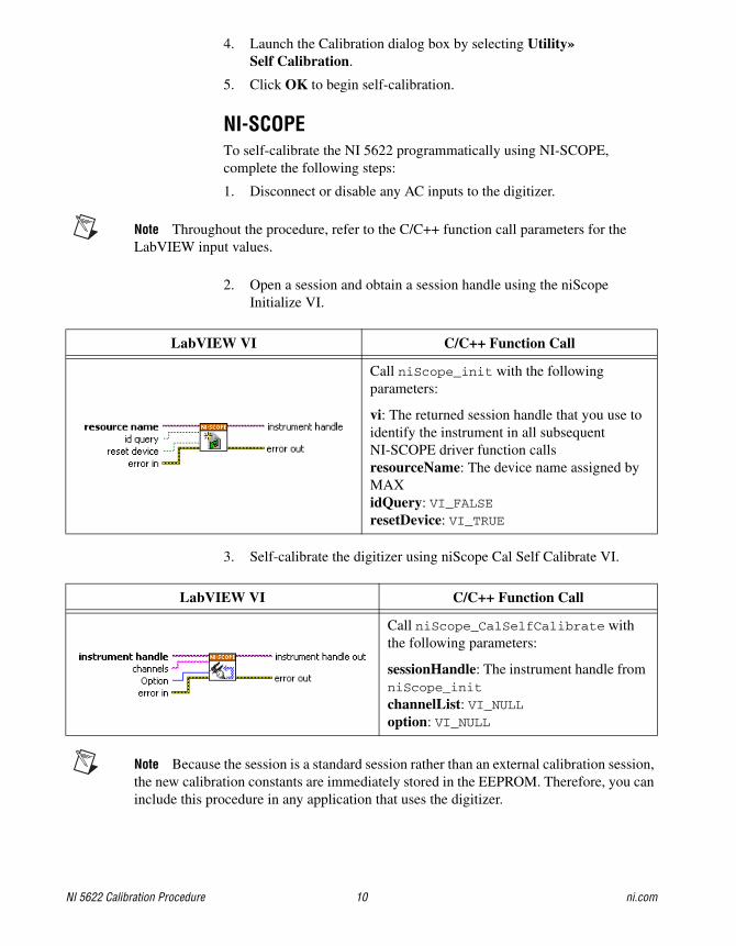
NI-SCOPETo self-calibrate the NI 5622 programmatically using NI-SCOPE, complete the following steps:
1. Disconnect or disable any AC inputs to the digitizer.
Note Throughout the procedure, refer to the C/C++ function call parameters for the LabVIEW input values.
2. Open a session and obtain a session handle using the niScope Initialize VI.
3. Self-calibrate the digitizer using niScope Cal Self Calibrate VI.
Note Because the session is a standard session rather than an external calibration session, the new calibration constants are immediately stored in the EEPROM. Therefore, you can include this procedure in any application that uses the digitizer.
LabVIEW VI C/C++ Function Call
Call niScope_init with the following parameters:
vi: The returned session handle that you use to identify the instrument in all subsequent NI-SCOPE driver function callsresourceName: The device name assigned by MAXidQuery: VI_FALSEresetDevice: VI_TRUE
LabVIEW VI C/C++ Function Call
Call niScope_CalSelfCalibrate with the following parameters:
sessionHandle: The instrument handle from niScope_init
channelList: VI_NULLoption: VI_NULL

© National Instruments Corporation 11 NI 5622 Calibration Procedure
4. End the session using the niScope Close VI.
Test Equipment Adjustment
Zero Power MeterZero the power meter by following the manufacturer’s recommended procedure.
Power Splitter Amplitude Imbalance CorrectionComplete the following steps to determine the power splitter amplitude imbalance correction factor used to verify and adjust the NI 5622.
1. Make the following connections:
a. Connect the signal generator to the source input port of the power splitter.
b. Connect the power meter to output port 1 of the power splitter.
c. Connect the 50 ohm terminator to output port 2 of the power splitter.
LabVIEW VI C/C++ Function Call
Call niScope_close with the following parameter:
vi: The instrument handle from niScope_init

NI 5622 Calibration Procedure 12 ni.com
Figure 1. Initial Connections for Power Splitter Amplitude Imbalance Correction
2. Configure the signal generator to generate a 100 MHz, 0.6325 Vpk-pk
sine wave.
3. Wait the amount of time the manufacturer recommends for the output to settle.
4. Measure the power (in watts) of the sine wave using the power meter. This value is the Measured Sine Wave Power of Port 1 used in step 7.
5. Make the following connection changes:
a. Connect the power meter to input port 2 of the power splitter.
b. Connect the 50 Ω terminator to input port 1 of the power splitter.
1 R&S NRP-Z91 Power Meter2 Weinschel WA 1507R Splitter
3 50 Ω Termination4 To Signal Generator
2
S
1
1
2
4
3

© National Instruments Corporation 13 NI 5622 Calibration Procedure
Figure 2. Connection Changes for Power Splitter Amplitude Imbalance Correction
6. Measure the power (in watts) of the sine wave using the power meter. This value is the Measured Sine Wave Power of Port 2 used in step 7.
7. Calculate the amplitude imbalance between the two output ports of the power splitter using the following formula:
Splitter Power Correction
where
a = Measured Sine Wave Power of Port 1
b = Measured Sine Wave Power of Port 2
The Splitter Power Correction (in dB) is used in the Absolute Amplitude Accuracy, and Adjustment sections of this document.
Note Make note of which output port of the power splitter is port 1 and which is port 2. Refer to the power splitter documentation for information on port designations. Reversing the connection in the adjustment and verification steps may invalidate the calibration of the NI 5622.
1 50 Ω Termination2 Weinschel WA 1507R Splitter
3 To Signal Generator4 R&S NRP-Z91 Power Meter
2
S
1
4
1
3
2
10 log10× ba---
=

NI 5622 Calibration Procedure 14 ni.com
VerificationThis section describes the program you must write to verify the performance of the NI 5622 to the published specifications for the device.
Note If any of these tests fail immediately after you perform an external adjustment, make sure that you have met the requirements listed in the Test Equipment and Test Conditions sections before you return the digitizer to National Instruments for repair.
Absolute Amplitude AccuracyComplete the following steps to verify the absolute amplitude accuracy of the NI 5622.
1. Make the following connections:
a. Connect the signal generator to the source input port of the power splitter using the SMA cable.
b. Connect the power meter to output port 1 of the of the power splitter.
c. Connect channel 0 (IF IN) of the digitizer to output port 2 of the power splitter.
Figure 3. NI 5622 Absolute Amplitude Accuracy Connections
1 R&S NRP-Z91 Power Meter2 Weinschel WA 1507R Splitter
3 To Signal Generator
NI PXIe-562216-Bit IF Digitizer
ACCESS ACTIVE
PFI 1
IF IN
CLK IN
CLK OUT
TTL (+5 V MAX)
2
S
1
3
21

© National Instruments Corporation 15 NI 5622 Calibration Procedure
2. Open a session and obtain a session handle using the niScope Initialize VI.
3. Configure the input impedance and the maximum input frequency using the niScope Configure Chan Characteristics VI.
4. Configure the common vertical properties using the niScope Configure Vertical VI.
LabVIEW VI C/C++ Function Call
Call niScope_init with the following parameters:
resourceName: The device name assigned by MAXidQuery: VI_FALSEresetDevice: VI_TRUE
LabVIEW VI C/C++ Function Call
Call niScope_ConfigureChanCharacteristics with the following parameters:
vi: The instrument handle from niScope_init
channelList: “0”inputImpedance: NISCOPE_VAL_50_OHMmaxInputFrequency: 250,000,000
LabVIEW VI C/C++ Function Call
Call niScope_ConfigureVertical with the following parameters:
vi: The instrument handle from niScope_init
channelList: “0”range: The Range value listed in Table 4 for the current iterationoffset: 0.0coupling: NISCOPE_VAL_ACprobeAttenuation: 1.0enabled: NISCOPE_VAL_TRUE

NI 5622 Calibration Procedure 16 ni.com
5. Configure the horizontal properties using the niScope Configure Horizontal Timing VI.
6. Configure the bandpass filter using the niScope Property Node.
7. Commit all the parameter settings to hardware using the niScope Commit VI.
LabVIEW VI C/C++ Function Call
Call niScope_ConfigureHorizontalTiming with the following parameters:
vi: The instrument handle from niScope_init
enforceRealtime: NISCOPE_VAL_TRUE
numRecords: 1minSampleRate: 150,000,000refPosition: 0.0minNumPts: 524,288
LabVIEW VI C/C++ Function Call
Call niScope_SetAttributeViBoolean with the following parameters:
vi: The instrument handle from niScope_initchannelList: “0”attributeId: NISCOPE_ATTR_BANDPASS_FILTER_ENABLED
value: The Bandpass Filter value listed in Table 4 for the current iteration
LabVIEW VI C/C++ Function Call
Call niScope_Commit with the following parameter:
vi: The instrument handle from niScope_init

© National Instruments Corporation 17 NI 5622 Calibration Procedure
8. This step varies depending on the programming language used.
(LabVIEW) Configure the frequency response compensation using the Apply Frequency Response Compensation VI. The value returned is the Reference Flatness Gain Correction Factor used in step 15.
Note You can download the Apply Frequency Response Compensation VI from the NI Web site at ni.com/info. Use the Info Code ex6vhg.
(C/C++) Configure the custom coefficients for the equalization FIR filter of the digitizer. Use the following function and attribute calls to calculate the customer coefficients.
a. To get the frequency response of the digitizer, call niScope_GetFrequencyResponse.
b. To get the number of coefficients the FIR filter can accept, call the NISCOPE_ATTR_EQUALIZATION_NUM_COEFFICIENTS attribute.
c. To configure the custom coefficients for the FIR filter, call niScope_ConfigureEqualizationFilterCoefficients.
9. Configure the signal generator to generate an Input Frequency, Input Voltage sine wave for the current iteration in Table 4.
10. Wait the amount of time the manufacturer recommends for the output to settle.
11. Measure the power (in watts) of the sine wave using the power meter. This value is the Power Meter Measured Sine Wave Power used in step 15.
LabVIEW VI Input Parameters
Set the following parameters:
bandwidth: –1center frequency: The Reference Frequency value in Table 4 for the current iterationchannel: “0”apply flatness: TRUEcache: FALSE

NI 5622 Calibration Procedure 18 ni.com
12. Initiate a waveform acquisition using the niScope Initiate Acquisition VI.
13. Acquire a waveform using the niScope Fetch (poly) VI. Select the WDT instance of the VI. Use the default value for the timestamp Type parameter.
14. This step varies depending on the programming language used.
(LabVIEW) Measure the peak voltage of the sine wave being generated using the Extract Single Tone Information VI. This value is the Digitizer Measured Sine Wave Amplitude used in step 15.
(C/C++) Perform an FFT on the array of data from step 13.
LabVIEW VI C/C++ Function Call
Call niScope_InitiateAcquisition with the following parameter:
vi: The instrument handle from niScope_init
LabVIEW VI C/C++ Function Call
Call niScope_Fetch with the following parameters:
vi: The instrument handle from niScope_init
channelList: “0”timeout: 5.0numSamples: –1
LabVIEW Block Diagram Input Parameters
Set the following parameters:
advanced search»approx freq.: –1advanced search»search: 5export signals: 0 (none)

© National Instruments Corporation 19 NI 5622 Calibration Procedure
15. Calculate the absolute amplitude accuracy error using the following formula:
where
a = Digitizer Measured Sine Wave Amplitude
b = Reference Flatness Gain Correction Factor
c = Power Meter Measured Sine Wave Power
d = Splitter Power Correction
Compare the result to the Published Specifications for the current iteration listed in Table 4. If the results are within the selected test limit, the device has passed this portion of the verification.
16. Repeat steps 4 through 15 for each iteration in Table 4.
17. End the session using the niScope Close VI.
You have finished verifying the absolute amplitude accuracy for the NI 5622.
LabVIEW VI C/C++ Function Call
Call niScope_close with the following para meter:
vi: The instrument handle from niScope_init
error 10 log10× a b×( )2
c------------------- 20– d+=

NI 5622 Calibration Procedure20
ni.com
Table 4. NI 5622 Absolute Amplitude Accuracy Specifications Limits
Iteration Range (Vpk-pk) Bandpass FilterInput Voltage
(Vpk-pk)Reference
Frequency (MHz)
Specifications Limits
Max Level (dB) Min Level (dB)
1 0.7 NISCOPE_VAL_FALSE
0.35 53 0.4 –0.4
2 1.05
3 1 0.5 0.4 –0.4
4 1.5
5 1.4 0.7 0.4 –0.4
6 2.1
7 0.7 NISCOPEVAL_TRUE
0.35 187.55 0.5 –0.5
8 1.05
9 1 0.5 0.5 –0.5
10 1.5
11 1.4 0.7 0.5 –0.5
12 2.1

© National Instruments Corporation 21 NI 5622 Calibration Procedure
Bandpass Amplitude FlatnessComplete the following steps to verify the bandpass amplitude flatness of the NI 5622.
1. Make the following connections:
a. Connect the signal generator to the source input port of the power splitter using the SMA cable.
b. Connect the power meter to output port 1 of the power splitter.
c. Connect channel 0 (IF IN) of the digitizer to output port 2 of the power splitter.
Figure 4. NI 5622 Bandpass Amplitude Flatness Connections
1 R&S NRP-Z91 Power Meter2 Weinschel WA 1507R Splitter
3 To Signal Generator
NI PXIe-562216-Bit IF Digitizer
ACCESS ACTIVE
PFI 1
IF IN
CLK IN
CLK OUT
TTL (+5 V MAX)
2
S
1
3
21

NI 5622 Calibration Procedure 22 ni.com
2. Open a session and obtain a session handle using the niScope Initialize VI.
3. Configure the input impedance and the maximum input frequency using the niScope Configure Chan Characteristics VI.
4. Configure the common vertical properties using the niScope Configure Vertical VI.
LabVIEW VI C/C++ Function Call
Call niScope_init with the following parameters:
resourceName: The device name assigned by MAXidQuery: VI_FALSEresetDevice: VI_TRUE
LabVIEW VI C/C++ Function Call
Call niScope_ConfigureChanCharacteristics with the following parameters:
vi: The instrument handle from niScope_init
channelList: “0”inputImpedance: NISCOPE_VAL_50_OHM
maxInputFrequency: 250,000,000
LabVIEW VI C/C++ Function Call
Call niScope_ConfigureVertical with the following parameters:
vi: The instrument handle from niScope_init
channelList: “0”range: 1.0 offset: 0.0coupling: NISCOPE_VAL_ACprobeAttenuation: 1.0enabled: NISCOPE_VAL_TRUE

© National Instruments Corporation 23 NI 5622 Calibration Procedure
5. Configure the horizontal properties using the niScope Configure Horizontal Timing VI.
6. Configure the bandpass filter using the niScope Property Node.
7. Commit all the parameter settings to hardware using the niScope Commit VI.
LabVIEW VI C/C++ Function Call
Call niScope_ConfigureHorizontalTiming with the following parameters:
vi: The instrument handle from niScope_init
enforceRealtime: NISCOPE_VAL_TRUEnumRecords: 1minSampleRate: 150,000,000refPosition: 0.0minNumPts: 524,288
LabVIEW VI C/C++ Function Call
Call niScope_SetAttributeViBoolean with the following parameters:
vi: The instrument handle from niScope_initchannelList: “0”attributeId: NISCOPE_ATTR_BANDPASS_FILTER_ENABLED
value: The Bandpass Filter value listed in Table 5 for the current iteration
LabVIEW VI C/C++ Function Call
Call niScope_Commit with the following parameter:
vi: The instrument handle from niScope_init

NI 5622 Calibration Procedure 24 ni.com
8. This step varies depending on the programming language used.
(LabVIEW) Configure the frequency response compensation using the Apply Frequency Response Compensation VI. The value returned is the Reference Flatness Gain Correction Factor used in step 23.
Note The Apply Frequency Response Compensation VI is available for download from the NI Web site at ni.com/info. Use the Info Code ex6vhg.
(C/C++) Configure the custom coefficients for the equalization FIR filter of the digitizer. Use the following function and attribute calls to calculate the customer coefficients.
a. To get the frequency response of the digitizer, call niScope_GetFrequencyResponse.
b. To get the number of coefficients the FIR filter can accept, query the NISCOPE_ATTR_EQUALIZATION_NUM_COEFFICIENTS attribute.
c. To configure the custom coefficients for the FIR filter, call niScope_ConfigureEqualizationFilterCoefficients.
9. Configure the signal generator to output a Reference Frequency, 1.25 Vpk-pk sine wave for the current iteration in Table 5.
10. Wait the amount of time the manufacturer recommends for the output to settle.
11. Measure the power (in watts) of the sine wave using the power meter. This value is the Power Meter Measured Sine Wave Reference Power used in step 23.
LabVIEW VI Input Parameters
Set the following parameters:
bandwidth: –1center frequency: The Reference Frequency value in Table 5 for the current iterationchannel: “0”apply flatness: TRUEcache: FALSE

© National Instruments Corporation 25 NI 5622 Calibration Procedure
12. Initiate a waveform acquisition using the niScope Initiate Acquisition VI.
13. Acquire a waveform using the niScope Fetch (poly) VI. Select the WDT instance of the VI. Use the default value for the timestamp Type parameter.
14. This step varies depending on the programming language used.
(LabVIEW) Measure the Vpk-pk of the sine wave being generated using the LabVIEW Extract Single Tone Information VI. This value is the Digitizer Measured Sine Wave Reference Amplitude used in step 23.
(C/C++) Perform an FFT on the array of data from step 13.
LabVIEW VI C/C++ Function Call
Call niScope_InitiateAcquisition with the following parameter:
vi: The instrument handle from niScope_init
LabVIEW VI C/C++ Function Call
Call niScope_Fetch with the following parameters:
vi: The instrument handle from niScope_init
channelList: “0”timeout: 5.0numSamples: –1
LabVIEW Block Diagram Input Parameters
Set the following parameters:
advanced search»approx freq.: –1advanced search»search: 5export signals: 0 (none)
NI 5622 Calibration Procedure 26 ni.com
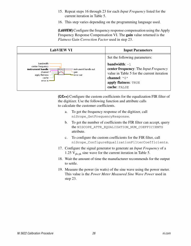
15. Repeat steps 16 through 23 for each Input Frequency listed for the current iteration in Table 5.
16. This step varies depending on the programming language used.
(LabVIEW) Configure the frequency response compensation using the Apply Frequency Response Compensation VI. The gain value returned is the Flatness Gain Correction Factor used in step 23.
(C/C++) Configure the custom coefficients for the equalization FIR filter of the digitizer. Use the following function and attribute calls to calculate the customer coefficients.
a. To get the frequency response of the digitizer, call niScope_GetFrequencyResponse.
b. To get the number of coefficients the FIR filter can accept, query the NISCOPE_ATTR_EQUALIZATION_NUM_COEFFICIENTS attribute.
c. To configure the custom coefficients for the FIR filter, call niScope_ConfigureEqualizationFilterCoefficients.
17. Configure the signal generator to generate an Input Frequency of a 1.25 Vpk-pk sine wave for the current iteration in Table 5.
18. Wait the amount of time the manufacturer recommends for the output to settle.
19. Measure the power (in watts) of the sine wave using the power meter. This value is the Power Meter Measured Sine Wave Power used in step 23.
LabVIEW VI Input Parameters
Set the following parameters:
bandwidth: –1center frequency: The Input Frequency value in Table 5 for the current iterationchannel: “0”apply flatness: TRUEcache: FALSE

© National Instruments Corporation 27 NI 5622 Calibration Procedure
20. Initiate a waveform acquisition using the niScope Initiate Acquisition VI.
21. Acquire a waveform using the niScope Fetch (poly) VI. Select the WDT instance of the VI. Use the default value for the timestamp Type parameter.
22. This step varies depending on the programming language used.
(LabVIEW) Measure the Vpk-pk of the sine wave being generated using the LabVIEW Extract Single Tone Information VI. This value is the Digitizer Measured Sine Wave Amplitude used in step 23.
(C/C++) Perform an FFT on the array of data from step 21.
LabVIEW VI C/C++ Function Call
Call niScope_InitiateAcquisition with the following parameter:
vi: The instrument handle from niScope_init
LabVIEW VI C/C++ Function Call
Call niScope_Fetch with the following parameters:
vi: The instrument handle from niScope_init
channelList: “0”timeout: 5.0numsamples: –1
LabVIEW Block Diagram Input Parameters
Set the following parameters:
advanced search»approx freq.: –1advanced search»search: 5export signals: 0 (none)

NI 5622 Calibration Procedure 28 ni.com
23. Calculate the power difference using the following formula:
where
a = Digitizer Measured Sine Wave Amplitude
b = Flatness Gain Correction Factor
c = Power Meter Measured Sine Wave Power
d = Digitizer Measured Sine Wave Reference Amplitude
e = Reference Flatness Gain Correction Factor
f = Power Meter Measured Sine Wave Reference Power
Compare the result to the Published Specifications for the current iteration listed in Table 5. If the results are within the selected test limit, the device has passed this portion of the verification.
24. Repeat steps 6 through 23 for each iteration in Table 5.
25. End the session using the niScope Close VI.
You have finished verifying the bandpass amplitude flatness for the NI 5622.
LabVIEW VI C/C++ Function Call
Call niScope_close with the following parameter:
vi: The instrument handle from niScope_init
power 10 log10×a b×( )2 f×d e×( )2 c×
----------------------------
=

NI 5622 Calibration Procedure29
ni.com
Table 5. NI 5622 Bandpass Amplitude Flatness Published Specifications
Iteration Range (Vpk-pk) Bandpass FilterReference
Frequency (MHz)Input Frequency
(MHz)
Published Specifications
Max Level (dB) Min Level (dB)
1 1 NISCOPE_VAL_FALSE
53 34 0.35 –0.35
43
62
72
2 1 NISCOPE_VAL_FALSE
100.1 9.9 0.6 –0.6
37
64
91
118
144.5
172
199
226
250.1
3 1 NISCOPE_VAL_TRUE
187.55 162.4 0.35 –0.6
174.4
200.4
212.6

NI 5622 Calibration Procedure 30 ni.com
Timing AccuracyComplete the following steps to verify the timing accuracy of the NI 5622.
1. Connect the signal generator to channel 0 of the digitizer.
2. Open a session and obtain a session handle using the niScope Initialize VI.
3. Configure the input impedance and the maximum input frequency using the niScope Configure Chan Characteristics VI.
LabVIEW VI C/C++ Function Call
Call niScope_init with the following parameters:
resourceName: The device name assigned by MAXidQuery: VI_FALSEresetDevice: VI_TRUE
LabVIEW VI C/C++ Function Call
Call niScope_ConfigureChanCharacteristics with the following parameters:
vi: The instrument handle from niScope_init
inputImpedance: NISCOPE_VAL_50_OHM
maxInputFrequency: 250,000,000
© National Instruments Corporation 31 NI 5622 Calibration Procedure
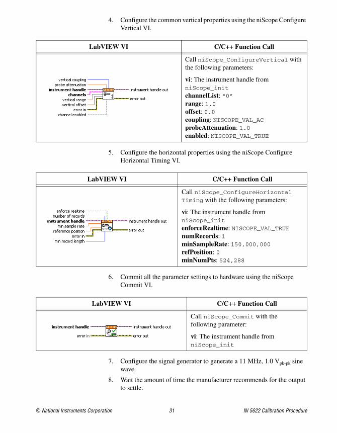
4. Configure the common vertical properties using the niScope Configure Vertical VI.
5. Configure the horizontal properties using the niScope Configure Horizontal Timing VI.
6. Commit all the parameter settings to hardware using the niScope Commit VI.
7. Configure the signal generator to generate a 11 MHz, 1.0 Vpk-pk sine wave.
8. Wait the amount of time the manufacturer recommends for the output to settle.
LabVIEW VI C/C++ Function Call
Call niScope_ConfigureVertical with the following parameters:
vi: The instrument handle from niScope_init
channelList: “0”range: 1.0 offset: 0.0coupling: NISCOPE_VAL_ACprobeAttenuation: 1.0enabled: NISCOPE_VAL_TRUE
LabVIEW VI C/C++ Function Call
Call niScope_ConfigureHorizontalTiming with the following parameters:
vi: The instrument handle from niScope_init
enforceRealtime: NISCOPE_VAL_TRUEnumRecords: 1minSampleRate: 150,000,000refPosition: 0minNumPts: 524,288
LabVIEW VI C/C++ Function Call
Call niScope_Commit with the following parameter:
vi: The instrument handle from niScope_init

NI 5622 Calibration Procedure 32 ni.com
9. Initiate a waveform acquisition using the niScope Initiate Acquisition VI.
10. Acquire a waveform using the niScope Fetch (poly) VI. Select the WDT instance of the VI. Use the default value for the timestamp Type parameter.
11. This step varies depending on the programming language used.
(LabVIEW) Measure the frequency of the sine wave being generated using the Extract Single Tone Information VI.
(C/C++) Perform an FFT on the array of data from step 10.
LabVIEW VI C/C++ Function Call
Call niScope_InitiateAcquisition with the following parameter:
vi: The instrument handle from niScope_init
LabVIEW VI C/C++ Function Call
Call niScope_Fetch with the following parameters:
vi: The instrument handle from niScope_init
channelList: “0”timeout: 5.0numsamples: –1
LabVIEW Block Diagram Input Parameters
Set the following parameters:
advanced search»approx freq.: –1advanced search»search: 5export signals: 0 (none)

© National Instruments Corporation 33 NI 5622 Calibration Procedure
12. Calculate the error in timing as parts per million (ppm) using the following formula:
where a is the measured frequency.
Compare the result to the Published Specification listed in Table 6. If the result is within the selected test limit, the device has passed this portion of the verification.
13. End the session using the niScope Close VI.
You have finished verifying the timing accuracy for the NI 5622.
LabVIEW VI C/C++ Function Call
Call niScope_close with the following parameter:
vi: The instrument handle from niScope_init
Table 6. NI 5622 Timing Accuracy Specification Limit
Input Frequency Specification
11 MHz 5 ppm
error a 11 000 000, ,–( )11-------------------------------------------=

NI 5622 Calibration Procedure 34 ni.com
SSB Phase NoiseComplete the following steps to verify the single sideband phase noise of the NI 5622.
1. Make the following connections:
a. Connect the 3 dB attenuator to the signal generator.
b. Connect the SMA cable to the 3 dB attenuator.
c. Connect channel 0 (IF IN) of the digitizer to the other end of the SMA cable.
2. Open a session and obtain a session handle using the niScope Initialize VI.
3. Configure the input impedance and the maximum input frequency using the niScope Configure Chan Characteristics VI.
LabVIEW VI C/C++ Function Call
Call niScope_init with the following parameters:
resourceName: The device name assigned by MAXidQuery: VI_FALSEresetDevice: VI_TRUE
LabVIEW VI C/C++ Function Call
Call niScope_ConfigureChanCharacteristics with the following parameters:
vi: The instrument handle from niScope_init
channelList: “0”inputImpedance: NISCOPE_VAL_50_OHM
maxInputFrequency: 250,000,000

© National Instruments Corporation 35 NI 5622 Calibration Procedure
4. Configure the common vertical properties using the niScope Configure Vertical VI.
5. Configure the horizontal properties using the niScope Configure Horizontal Timing VI.
6. Configure the analog dither using the niScope Property Node.
LabVIEW VI C/C++ Function Call
Call niScope_ConfigureVertical with the following parameters:
vi: The instrument handle from niScope_init
channelList: “0”range: 1.0offset: 0.0coupling: NISCOPE_VAL_ACprobeAttenuation: 1.0enabled: NISCOPE_VAL_TRUE
LabVIEW VI C/C++ Function Call
Call niScope_ConfigureHorizontalTiming with the following parameters:
vi: The instrument handle from niScope_init
enforceRealtime: NISCOPE_VAL_TRUEnumRecords: 1minSampleRate: 150,000,000refPosition: 0.0minNumPts: 31,000,000
LabVIEW VI C/C++ Function Call
Call niScope_ SetAttributeViBoolean with the following parameters:
vi: The instrument handle from niScope_initchannelList: “0”attributeId: NISCOPE_ATTR_DITHER_ENABLEDvalue: NISCOPE_VAL_TRUE

NI 5622 Calibration Procedure 36 ni.com
7. Configure the bandpass filter using the niScope Property Node.
8. Commit all the parameter settings to hardware using the niScope Commit VI.
9. Configure the signal generator to generate an Input Frequency of a 1.3 Vpk-pk sine wave for the current iteration in Table 7.
10. Wait the amount of time the manufacturer recommends for the output of the signal generator to settle.
11. Initiate a waveform acquisition using the niScope Initiate Acquisition VI.
LabVIEW VI C/C++ Function Call
Call niScope_SetAttributeViBoolean with the following parameters:
vi: The instrument handle from niScope_initchannelList: “0”attributeId: NISCOPE_ATTR_BANDPASS_ FILTER_ENABLED
value: The Bandpass Filter value listed in Table 7 for the current iteration
LabVIEW VI C/C++ Function Call
Call niScope_Commit with the following parameter:
vi: The instrument handle from niScope_init
LabVIEW VI C/C++ Function Call
Call niScope_InitiateAcquisition with the following parameter:
vi: The instrument handle from niScope_init

© National Instruments Corporation 37 NI 5622 Calibration Procedure
12. Fetch in chunks the waveform in digitizer memory by repeating steps 12a through 12e thirty-one times. The result is a downconverted, resampled waveform used in step 13.
a. Configure which point in the acquired waveform is the first to be fetched using the niScope Property Node.
b. Acquire a waveform using the niScope Fetch (poly) VI. Select the WDT instance of the VI. Use the default value for the timestamp Type parameter.
LabVIEW VI C/C++ Function Call
Call niScope_SetAttributeViInt32 with the following parameters:
vi: The instrument handle from niScope_initchannelList: “0”attributeId: NISCOPE_ATTR_FETCH_RELATIVE_TO
value: NISCOPE_VAL_START (for iteration 1), NISCOPE_VAL_READ_POINTER (for iterations 2 through 31)
LabVIEW VI C/C++ Function Call
Call niScope_Fetch with the following parameters:
vi: The instrument handle from niScope_init
channelList: “0”timeout: 5.0numSamples: 1,000,000

NI 5622 Calibration Procedure 38 ni.com
c. Downconvert the acquired waveform using the MT Downconvert Passband VI located: <LabVIEW Directory>\vi.lib\addons\Modulation\Analog. Select the Real Input instance of this VI.
LabVIEW VI C/C++ Function Call
Call ModtDownconvertPassband with the following parameters:
Handle: The handle you obtained from ModtCreateSessionHandle
t0: Trigger (start) time of the acquired waveformdt: Time interval between data points in the acquired waveforminputData: Acquired waveform data array inputDataNumElements: 1,000,000
carrierFrequency: The Alias Frequency value in Table 7 for the current iterationpassbandBandwidth: 1,000,000initialPhase: 0reset: TRUE (for iteration 1), FALSE (for iterations 2 through 31)enableFilter: TRUE

© National Instruments Corporation 39 NI 5622 Calibration Procedure
d. Resample the complex waveform using the MT Resample (Complex Cluster) VI located at <LabVIEW Directory>\vi.lib\addons\Modulation\Analog.
e. Concatenate the complex value time-domain data array returned in step 12d to the end of the previous result.
LabVIEW VI C/C++ Function Call
Call ModtFractionalResample with the following parameters:
Handle: The handle you obtained from ModtCreateSessionHandle
t0: Trigger (start) time of the downconverted I/Q signal datadt: Time interval between data points in the downconverted I/Q signal datainputData: Complex value time-domain data array inumInputDataSamples: Number of samples in the complex value time-domain data arrayinitialSampleOffset: 0desiredSampleRate: 5,000,000reset: TRUE (for iteration 1), FALSE (for iterations 2 through 31)numResampledComplexDataSamples: ceil (dt × numInputDataSamples × desiredSampleRate)

NI 5622 Calibration Procedure 40 ni.com
13. This step varies depending on the programming language used.
(LabVIEW) Calculate the SSB phase noise of the acquired signal using the mod_Phase Noise Calculation VI located at: <LabVIEW Directory>\vi.lib\addons\Modulation\Analog\support.
(C/C++) Calculate the SSB phase noise of the acquired signal.
14. Repeat steps 11 through 13 fifteen times to obtain an average SSB phase noise spectrum.
15. Compare the last phase noise results to the Published Specifications for the current iteration listed in Table 7. If the results are within the selected test limit, the device has passed this portion of the verification.
16. Repeat steps 7 through 15, for each iteration in Table 7.
17. End the session using the niScope Close VI.
You have finished verifying the SSB phase noise for the NI 5622.
LabVIEW VI Input Parameters
Set the following parameters:
offset stop (Hz): 1,000,000IQ data (complex): Complex waveform from step 12 e window: Hanningrestart averaging (F): TRUE for iteration 1; FALSE for iterations 2 through 10averaging parameters»averaging mode: RMS averagingaveraging parameters»weighting mode: Linearaveraging parameters»number of averages: 15desired offset values (Hz): [100, 1000, 10000]
LabVIEW VI C/C++ Function Call
Call niScope_close with the following parameter:
vi: The instrument handle from niScope_init

NI 5622 Calibration Procedure41
ni.com
Table 7. NI 5622 SSB Phase Noise Specifications Limits
Iteration Bandpass Filter Input Frequency (MHz) Alias Frequency (MHz)
Specifications Limits
Carrier Offset
100 Hz 1 kHz 10 kHz
1 NISCOPE_VAL_FALSE
53.1 53.1 –90 dBc/Hz –128 dBc/Hz –141 dBc/Hz
2 NISCOPE_VAL_TRUE
187.1 37.1 –80 dBc/Hz –117 dBc/Hz –134 dBc/Hz

NI 5622 Calibration Procedure 42 ni.com
Average Noise DensityComplete the following steps to verify the average noise density of the NI 5622.
1. Connect the 50 ohm terminator directly to channel 0 of the digitizer.
2. Open a session and obtain a session handle using the niScope Initialize VI.
3. Configure the input impedance and the maximum input frequency using the niScope Configure Chan Characteristics VI.
LabVIEW VI C/C++ Function Call
Call niScope_init with the following parameters:
resourceName: The device name assigned by MAXidQuery: VI_FALSEresetDevice: VI_TRUE
LabVIEW VI C/C++ Function Call
Call niScope_ConfigureChanCharacteristics with the following parameters:
vi: The instrument handle from niScope_init
channelList: “0”inputImpedance: NISCOPE_VAL_50_OHM
maxInputFrequency: 250,000,000

© National Instruments Corporation 43 NI 5622 Calibration Procedure
4. Configure the common vertical properties using the niScope Configure Vertical VI.
5. Configure the horizontal properties using the niScope Configure Horizontal Timing VI.
6. Configure the bandpass filter using the niScope Property Node.
LabVIEW VI C/C++ Function Call
Call niScope_ConfigureVertical with the following parameters:
vi: The instrument handle from niScope_init
channelList: “0”range: The Range value in Table 8for the current iterationoffset: 0.0coupling: NISCOPE_VAL_ACprobeAttenuation: 1.0enabled: NISCOPE_VAL_TRUE
LabVIEW VI C/C++ Function Call
Call niScope_ConfigureHorizontalTiming with the following parameters:
vi: The instrument handle from niScope_init
enforceRealtime: NISCOPE_VAL_TRUEnumRecords: 1minSampleRate: 150,000,000refPosition: 50.0minNumPts: 524,288
LabVIEW VI C/C++ Function Call
Call niScope_SetAttributeViBoolean with the following parameters:
vi: The instrument handle from niScope_initchannelList: “0”attributeId: NISCOPE_ATTR_BANDPASS_FILTER_ENABLED
value: The Bandpass Filter value listed in Table 8 for the current iteration

NI 5622 Calibration Procedure 44 ni.com
7. Commit all the parameter settings to hardware using the niScope Commit VI.
8. Initiate a waveform acquisition using the niScope Initiate Acquisition VI.
9. Acquire a waveform using the niScope Fetch (poly) VI. Select the WDT instance of the VI. Use the default value for the timestamp Type parameter.
LabVIEW VI C/C++ Function Call
Call niScope_Commit with the following parameter:
vi: The instrument handle from niScope_init
LabVIEW VI C/C++ Function Call
Call niScope_InitiateAcquisition with the following parameter:
vi: The instrument handle from niScope_init
LabVIEW VI C/C++ Function Call
Call niScope_Fetch with the following parameters:
vi: The instrument handle from niScope_init
channelList: “0”timeout: 5.0numSamples: –1

© National Instruments Corporation 45 NI 5622 Calibration Procedure
10. This step varies depending on the programming language used.
(LabVIEW) Compute the averaged power spectral density in Vrms2/Hz using
the FFT Power Spectral Density for 1 Chan VI.
(C/C++) Calculate the power spectral density on the array of data from step 9.
11. Repeat steps 8 through 10 ten times to obtain an averaged power spectral density.
12. Compute the average noise density from the averaged power spectral density data using the following formula:
where
df = frequency resolution of the spectrum, in Hz
x = average power spectral density data, in Vrms2/Hz
Compare the result to the Published Specifications for the current iteration listed in Table 8. If the result is within the selected test limit, the device has passed this portion of the verification.
13. Repeat steps 4 through 12 for each iteration in Table 8.
LabVIEW VI Input Parameters
Set the following parameters:
restart averaging (F): TRUE for iteration 1; FALSE for iterations 2 through 10window: RectangledB On (F): FALSEaveraging parameters»averaging mode: RMS averagingaveraging parameters»weighting mode: Linearaveraging parameters»number of averages: 10
average noise density 10 log10×xk df×
k 1=
n
n------------------------------
2
20×
df--------------------------------------------------
=

NI 5622 Calibration Procedure 46 ni.com
14. End the session using the niScope Close VI.
You have finished verifying the average noise density for the NI 5622.
Adjustment
An adjustment is required only once a year. Following the adjustment procedure automatically updates the calibration date and temperature in the digitizer EEPROM.
Complete the following steps to externally adjust the NI 5622.
1. Make the following connections:
a. Connect the signal generator to the source input port of the power splitter.
b. Connect the power meter to output port 1 of the power splitter.
c. Connect channel 0 (IF IN) of the digitizer to output port 2 of the power splitter.
LabVIEW VI C/C++ Function Call
Call niScope_close with the following parameter:
vi: The instrument handle from niScope_init
Table 8. NI 5622 Average noise Density Published Specifications
Iteration Range (Vpp) Bandpass FilterPublished Specifications
(dBm/Hz)
1 0.7 NISCOPE_VAL_FALSE –146
2 1 NISCOPE_VAL_FALSE –143
3 1.4 NISCOPE_VAL_FALSE –140
4 0.7 NISCOPE_VAL_TRUE –146
5 1 NISCOPE_VAL_TRUE –143
6 1.4 NISCOPE_VAL_TRUE –140
© National Instruments Corporation 47 NI 5622 Calibration Procedure
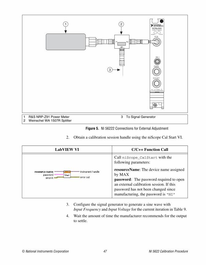
Figure 5. NI 56222 Connections for External Adjustment
2. Obtain a calibration session handle using the niScope Cal Start VI.
3. Configure the signal generator to generate a sine wave with Input Frequency and Input Voltage for the current iteration in Table 9.
4. Wait the amount of time the manufacturer recommends for the output to settle.
1 R&S NRP-Z91 Power Meter2 Weinschel WA 1507R Splitter
3 To Signal Generator
LabVIEW VI C/C++ Function Call
Call niScope_CalStart with the following parameters:
resourceName: The device name assigned by MAXpassword: The password required to open an external calibration session. If this password has not been changed since manufacturing, the password is “NI”
NI PXIe-562216-Bit IF Digitizer
ACCESS ACTIVE
PFI 1
IF IN
CLK IN
CLK OUT
TTL (+5 V MAX)
2
S
1
3
21

NI 5622 Calibration Procedure 48 ni.com
5. Measure the power (in watts) of the sine wave using the power meter. This value is the Power Meter Measured Sine Wave Power. Use this value to calculate the Measure Sine Wave Amplitude used in step 6.
where
a = Power Meter Measure Sine Wave Power
b = Power Splitter Power Correction
6. Adjust the vertical range using the niScope Cal Adjust Range VI.
7. Repeat steps 5 and 6. The first iteration configures the digitizer, and the second iteration performs the adjustment.
8. Repeat steps 3 through 7 for each iteration in Table 9.
9. Configure the signal generator to output a 15 MHz, 1.25 Vpk-pk sine wave.
10. Wait the amount of time the manufacturer recommends for the output of the signal generator to settle.
11. Adjust the sample rate using the niScope Cal Adjust VCXO VI.
12. Set Index = 0.
LabVIEW VI C/C++ Function Call
Call niScope_CalAdjustRange with the following parameters:
sessionHandle: The session handle from niScope_CalStart
channelName: “0”range: The Range value in Table 9 for the current iterationstimulus: The Measured Sine Wave Amplitude value
LabVIEW VI C/C++ Function Call
Call niScope_CalAdjustVCXO with the following parameters:
sessionHandle: The session handle from niScope_CalStartstimulusFreq: 15,000,000
Measured Sine Wave Amplitude 10 a× 10b20------
×=

© National Instruments Corporation 49 NI 5622 Calibration Procedure
13. Repeat steps 13a through 13e until you reach the Stop Frequency for the current iteration in Table 10.
a. Configure the signal generator to generate a 0.8 Vpk-pk sine wave with a frequency equal to the following formula:
Frequency = (Start Frequency + (Index × Frequency Step))
for the current iteration in Table 10.
b. Wait the amount of time the manufacturer recommends for the output to settle.
c. Measure the power (in watts) of the sine wave using the power meter. This value is the Power Meter Measure Sine Wave Power. Use this value to calculate the Measured Sine Wave Amplitude used in step 13d.
where
a = Power Meter Measure Sine Wave Power
b = Splitter Power Correction
d. Adjust the frequency response using the niScope Cal Adjust Frequency Response VI.
e. Increment Index by 1.
14. Repeat steps 12 and 13 for each iteration in Table 10.
15. Disconnect or disable all inputs to the digitizer.
LabVIEW VI C/C++ Function Call
Call niScope_CalAdjustFrequencyResponse with the following parameters:
sessionHandle: The session handle from niScope_CalStart
channelName: “0”range: 1stimulusAmp: The Measured Sine Wave Amplitude value stimulusFreq: The current frequency the signal generator is generating
Measured Sine Wave Amplitude 10 a× 10b20------
×=

NI 5622 Calibration Procedure 50 ni.com
16. Adjust the internal frequency response using the niScope Cal Adjust Frequency Response VI.
17. Self-calibrate the digitizer using niScope Cal Self Calibrate VI.
18. End the session and save the results using the niScope Cal End VI.
You have finished adjusting the NI 5622. You should repeat the entire verification procedure to verify a successful adjustment.
LabVIEW VI C/C++ Function Call
Call niScope_CalAdjustFrequencyResponse with the following parameters:
sessionHandle: The session handle from niScope_CalStart
channelName: “0”range: 1stimulusFreq: 187,000,000stimulusAmp: 0.2
LabVIEW VI C/C++ Function Call
Call niScope_CalSelfCalibrate with the following parameters:
sessionHandle: The instrument handle from niScope_CalStartchannelList: VI_NULLoption: VI_NULL
LabVIEW VI C/C++ Function Call
Call niScope_CalEnd with the following parameters:
sessionHandle: The instrument handle from niScope_CalStartaction: NISCOPE_VAL_ACTION_STORE

© National Instruments Corporation 51 NI 5622 Calibration Procedure
Appendix A: Calibration UtilitiesNI-SCOPE supports several calibration utilities you can use to retrieve information about adjustments performed on the NI 5622, change the external calibration password, and store small amounts of information in the onboard EEPROM. Although you can retrieve some data using MAX, you can retrieve all the data programmatically using NI-SCOPE functions.
MAXTo retrieve data using MAX, complete the following steps:
1. Select the device from which you want to retrieve information from My System»Devices and Interfaces»PXI System.
2. Select the Calibration tab in the lower right corner.
You should see information about the last date and temperature for both external and self-calibration.
Table 9. Input Parameters for Vertical Range External Adjustment
Iteration Range (V) Input Voltage (Vpk-pk) Input Frequency (MHz)
1 0.7 1 10
2 1 1.6 10
3 1.4 1.6 10
4 0.7 1 187
5 1 1.6 187
6 1.4 1.6 187
Table 10. Input Parameters for Frequency Range External Adjustment
IterationStart Frequency
(MHz)Stop Frequency
(MHz)Frequency Step
(MHz)
1 0.9 224.9 1
2 225.9 815.9 10
3 119.9 307.4 0.5

CVI, LabVIEW, National Instruments, NI, ni.com, the National Instruments corporate logo, and the Eagle logo are trademarks of National Instruments Corporation. Refer to the Trademark Information at ni.com/trademarks for other National Instruments trademarks. The mark LabWindows is used under a license from Microsoft Corporation. Windows is a registered trademark of Microsoft Corporation in the United States and other countries. Other product and company names mentioned herein are trademarks or trade names of their respective companies. For patents covering National Instruments products/technology, refer to the appropriate location: Help»Patents in your software, the patents.txt file on your media, or the National Instruments Patent Notice at ni.com/patents. Refer to the Export Compliance Information at ni.com/legal/export-compliance for the National Instruments global trade compliance policy and how to obtain relevant HTS codes, ECCNs, and other import/export data.
© 2009–2011 National Instruments Corporation. All rights reserved. 372669C-01 Nov11
NI-SCOPENI-SCOPE provides a full complement of calibration utility functions and VIs. Refer to the NI High-Speed Digitizers Help for the complete function reference and VI reference. The utility functions include:
• niScope Cal Change Password VI (niScope_CalChangePassword)
• niScope Cal Fetch Count VI (niScope_CalFetchCount)
• niScope Cal Fetch Date VI (niScope_CalFetchDate)
• niScope Cal Fetch Misc Info VI (niScope_CalFetchMiscInfo)
• niScope Cal Fetch Temperature VI (niScope_CalFetchTemperature)
• niScope Cal Store Misc Info VI (niScope_CalStoreMiscInfo)
Where to Go for SupportThe National Instruments Web site is your complete resource for technical support. At ni.com/support you have access to everything from troubleshooting and application development self-help resources to email and phone assistance from NI Application Engineers.
A Declaration of Conformity (DoC) is our claim of compliance with the Council of the European Communities using the manufacturer’s declaration of conformity. This system affords the user protection for electromagnetic compatibility (EMC) and product safety. You can obtain the DoC for your product by visiting ni.com/certification. If your product supports calibration, you can obtain the calibration certificate for your product at ni.com/calibration.
National Instruments corporate headquarters is located at 11500 North Mopac Expressway, Austin, Texas, 78759-3504. National Instruments also has offices located around the world to help address your support needs. For telephone support in the United States, create your service request at ni.com/support and follow the calling instructions or dial 512 795 8248. For telephone support outside the United States, visit the Worldwide Offices section of ni.com/niglobal to access the branch office Web sites, which provide up-to-date contact information, support phone numbers, email addresses, and current events.