nh-2700 (front load) operator manual · nh-2700 . revision record . date page version description...
TRANSCRIPT
NH-2700 (Front Load)
Operator Manual
Copyrightⓒ 2010 Nautilus Hyosung Inc. All right reserved
NH-2700
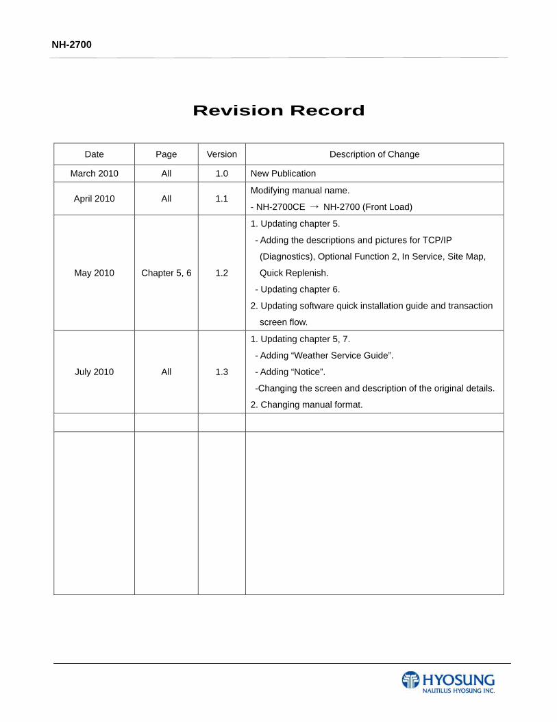
Revision Record
Date Page Version Description of Change
March 2010 All 1.0 New Publication
April 2010 All 1.1 Modifying manual name.
- NH-2700CE → NH-2700 (Front Load)
May 2010 Chapter 5, 6 1.2
1. Updating chapter 5.
- Adding the descriptions and pictures for TCP/IP
(Diagnostics), Optional Function 2, In Service, Site Map,
Quick Replenish.
- Updating chapter 6.
2. Updating software quick installation guide and transaction
screen flow.
July 2010 All 1.3
1. Updating chapter 5, 7.
- Adding “Weather Service Guide”.
- Adding “Notice”.
-Changing the screen and description of the original details.
2. Changing manual format.
NH-2700
Table of Contents
1. Introduction
1.1 About NH-2700 ·····································································································1-2
1.2 Basic Features ·······································································································1-2
1.3 What is in this Manual ···························································································1-4
1.4 Terminologies ·········································································································1-4
2. Precautions for Safety
2.1 Overview ·················································································································2-2
2.2 Description of Precaution Symbols ·····································································2-3
3. Hardware Specifications
3.1 Dimensions ············································································································3-2
3.2 Component Locations ···························································································3-3
3.3 LCD & Customer Keypad ······················································································3-6
3.4 Cash Dispenser Unit ····················································································3-7
3.5 Receipt Printer ·······································································································3-8
3.6 Magnetic Card Reader ·························································································3-9
3.7 Main Control Board ······························································································3-10
3.8 Operating Environment ·······················································································3-11
4. Operating Instructions
4.1 Opening and Closing the Door ·············································································4-2
4.2 Cash Dispenser ···········································································4-16
4.3 Receipt Printer ···········································································4-30
4.4 Magnetic Card Specifications ···········································································4-37
5. Operator Functions
5.1 Basic System Operation ····················································································5-2
5.2 Supervisor Menu ··················································································5-19
5.3 Settlement ··················································································5-23
5.4 Journal ··················································································5-25
5.5 Report ··················································································5-28
NH-2700
5.6 Diagnostics ··················································································5-36
5.7 Customer Setup ··················································································5-47
5.8 System Setup ··················································································5-89
5.9 Host Setup ················································································5-102
5.10 Transaction Setup ················································································5-123
5.11 Site Map ················································································5-126
5.12 Quick Replenish ················································································5-126
5.13 Quick Configuration ················································································5-129
6. Installation
6.1 Installation Information ···············································································6-2
6.2 System Installation ································································································6-3
6.3 Hardware Installation ·····························································································6-8
7. Appendix
7.1 Error Code Table ····················································································7-2
7.2 Installation Guide ························································································7-36
7.3 Transaction Screen Flow ··················································································7-47
7.4 Supported USB Memory and HUB ·····································································7-101
7.5 Advertisement Image Update Guide ····································································7-103
7.6 Background Image Update Guide ······································································7-117
7.7 Weather Service Guide ···················································································· 7-126
NH-2700 1. Introduction
11-
Chapter 1. Introduction
NH-2700 1. Introduction
21-
1. Introduction
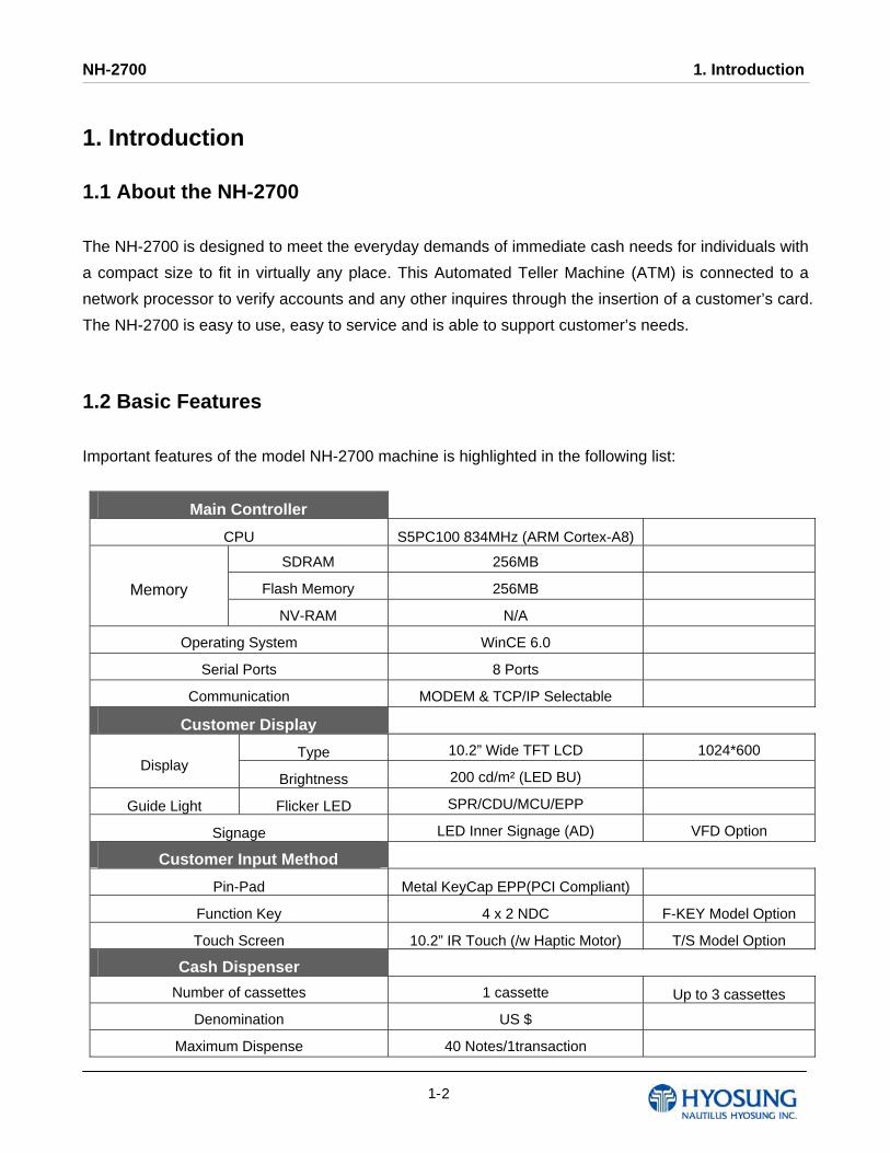
1.1 About the NH-2700
The NH-2700 is designed to meet the everyday demands of immediate cash needs for individuals with
a compact size to fit in virtually any place. This Automated Teller Machine (ATM) is connected to a
network processor to verify accounts and any other inquires through the insertion of a customer’s card.
The NH-2700 is easy to use, easy to service and is able to support customer’s needs.
1.2 Basic Features
Important features of the model NH-2700 machine is highlighted in the following list:
Main Controller
CPU S5PC100 834MHz (ARM Cortex-A8)
SDRAM 256MB
Flash Memory 256MB Memory
NV-RAM N/A
Operating System WinCE 6.0
Serial Ports 8 Ports
Communication MODEM & TCP/IP Selectable
Customer Display
Type 10.2” Wide TFT LCD 1024*600 Display
Brightness 200 cd/m² (LED BU)
Guide Light Flicker LED SPR/CDU/MCU/EPP
Signage LED Inner Signage (AD) VFD Option
Customer Input Method
Pin-Pad Metal KeyCap EPP(PCI Compliant)
Function Key 4 x 2 NDC F-KEY Model Option
Touch Screen 10.2” IR Touch (/w Haptic Motor) T/S Model Option
Cash Dispenser
Number of cassettes 1 cassette Up to 3 cassettes
Denomination US $
Maximum Dispense 40 Notes/1transaction

NH-2700 1. Introduction
31-
Cassette Capacity 2,000 notes / 1 cassette (new note)
Reject Type Note by Note Reject
(200 bills Max) Reject Bin
Card Reader
Type DIP Type EMV IC DIP Option
Magnetic Stripe ISO 1,2 Read
Receipt Printer
Printing Type Thermal Line Printing
Printing Width 80mm Max
Paper Setting Method Semi-Automatic
Type Thermal Roll Paper
Width Max. 80mm Paper
Specification Outer Diameter Max. 180Φ
Journal Printer
Journal Printer Electronic Journal
Safety
Safety UL Business-Hour Safety
Locking device Dial Lock Elec/Cencon Lock
Option
Alarm/Security
Alarm Box Option
Proximity Sensor
Option
Camera
CCD Camera Option
(/W SD Card)
Anti-Skimming Device IR detect Sensor Option
Additional Function
Audio guidance Support
ADA Audio guidance Support

NH-2700 1. Introduction
41-
1.3 What is in this manual
This NH-2700 Automated Teller Machine Manual contains all information needed for normal
operational use.
This manual contains Unit Specifications, ATM Opening & Closing Procedures, Operator Functions,
Customer Transactions, Error Recovery and etc.
Some of the information in this manual may differ according to the network processor to be connected.
1.4 Terminologies
In this document the terminology listed below is used as follows:
● Customer and consumer refer to any person who transacts business through the ATM.
● Device and unit refer to the standard and optional ATM equipment, such as monitors, card readers,
printers, and dispensers.
● Fascia refers to the entire front portion of the unit, including the portion where the customer
transacts business.
● Module refers to a plug-in device that can be serviced or replaced.
● Note(s) and bill(s) refer to the individual documents loaded into and dispensed from the dispenser.
● Operator refers to a person who performs daily servicing and maintenance tasks, such as
replenishing supplies and diagnosing certain problems.
● Screen refers to the text appearing on the customer display.
● Servicing and maintenance refer to the operator tasks performed to keep the terminal operational.
NH-2700 2. Precautions for Safety
12-
Chapter 2. Precautions for Safety

NH-2700 2. Precautions for Safety
22-
2. Precautions for Safety
2.1 Overview
Common Precaution for Safety
Please read the following instructions before operating equipment.
Operate equipment in the order outlined in this manual.
Follow precautions indicated in this manual, as well as the equipment itself.
Failure to properly address these precautions may lead to injury or damage to
the product.
Avoid operations not addressed in this manual.
If you cannot remedy system problems using the methods outlined in this manual,
please refer to contact information listed in the manual.
Any change or modifications in construction of this device which are not expressly approved
by the party responsible for compliance could void the user’s authority to operate the
equipment.
NOTE: This equipment has been tested and found to comply with the limits for a Class A digital
device, pursuant to part 15 of the FCC Rules. These limits are designed to provide reasonable
protection against harmful interference when the equipment is operated in a commercial
environment. This equipment generates, uses, and can radiate radio frequency energy and, if not
installed and used in accordance with the instruction manual, may cause harmful interference to
radio communications. Operation of this equipment in a residential area is likely to cause harmful
interference in which case the user will be required to correct the interference at his own expense.
Precautions outlined this manual provide information on safe and
proper handling of the product. Non-compliance of the precautions
may result in injury or damage to the product.
This precaution symbol with sample term tells you safety warnings
during equipment handlings.
NH-2700 2. Precautions for Safety
32-
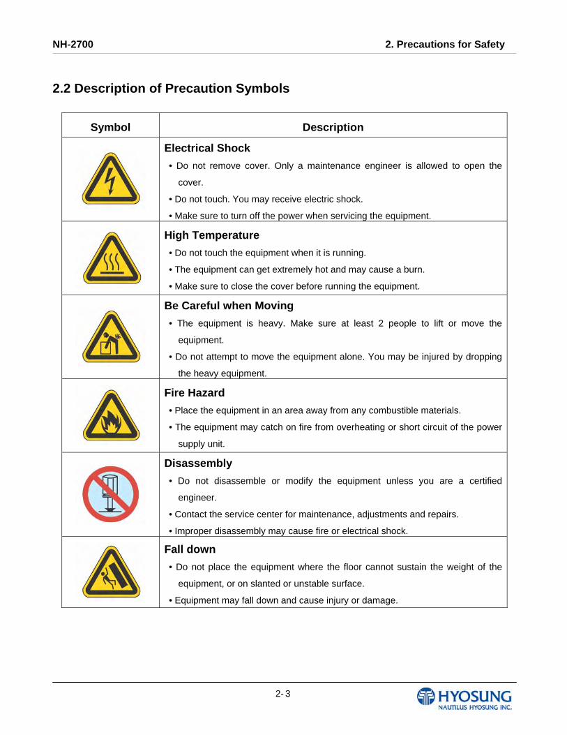
2.2 Description of Precaution Symbols
Symbol Description
Electrical Shock
• Do not remove cover. Only a maintenance engineer is allowed to open the
cover.
• Do not touch. You may receive electric shock.
• Make sure to turn off the power when servicing the equipment.
High Temperature
• Do not touch the equipment when it is running.
• The equipment can get extremely hot and may cause a burn.
• Make sure to close the cover before running the equipment.
Be Careful when Moving
• The equipment is heavy. Make sure at least 2 people to lift or move the
equipment.
• Do not attempt to move the equipment alone. You may be injured by dropping
the heavy equipment.
Fire Hazard
• Place the equipment in an area away from any combustible materials.
• The equipment may catch on fire from overheating or short circuit of the power
supply unit.
Disassembly
• Do not disassemble or modify the equipment unless you are a certified
engineer.
• Contact the service center for maintenance, adjustments and repairs.
• Improper disassembly may cause fire or electrical shock.
Fall down
• Do not place the equipment where the floor cannot sustain the weight of the
equipment, or on slanted or unstable surface.
• Equipment may fall down and cause injury or damage.
NH-2700 2. Precautions for Safety
42-
Symbol Description
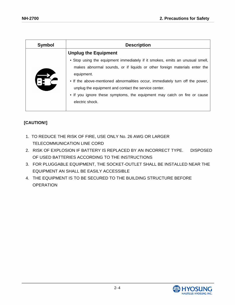
Unplug the Equipment
• Stop using the equipment immediately if it smokes, emits an unusual smell,
makes abnormal sounds, or if liquids or other foreign materials enter the
equipment.
• If the above-mentioned abnormalities occur, immediately turn off the power,
unplug the equipment and contact the service center.
• If you ignore these symptoms, the equipment may catch on fire or cause
electric shock.
[CAUTION!]
1. TO REDUCE THE RISK OF FIRE, USE ONLY No. 26 AWG OR LARGER
TELECOMMUNICATION LINE CORD
2. RISK OF EXPLOSION IF BATTERY IS REPLACED BY AN INCORRECT TYPE. DISPOSED
OF USED BATTERIES ACCORDING TO THE INSTRUCTIONS
3. FOR PLUGGABLE EQUIPMENT, THE SOCKET-OUTLET SHALL BE INSTALLED NEAR THE
EQUIPMENT AN SHALL BE EASILY ACCESSIBLE
4. THE EQUIPMENT IS TO BE SECURED TO THE BUILDING STRUCTURE BEFORE
OPERATION

NH-2700 3. Hardware Specifications
3- 1
Chapter 3. Hardware Specifications

NH-2700 3. Hardware Specifications
3- 2
3. Hardware Specifications 3.1 Dimensions Below figures show the overall physical dimensions of the NH-2700.
NOTE: All the units in the dimension is mm and ( ) is inch scale.
Fig. 3.1 NH-2700 Dimension
NH-2700 3. Hardware Specifications
3- 3
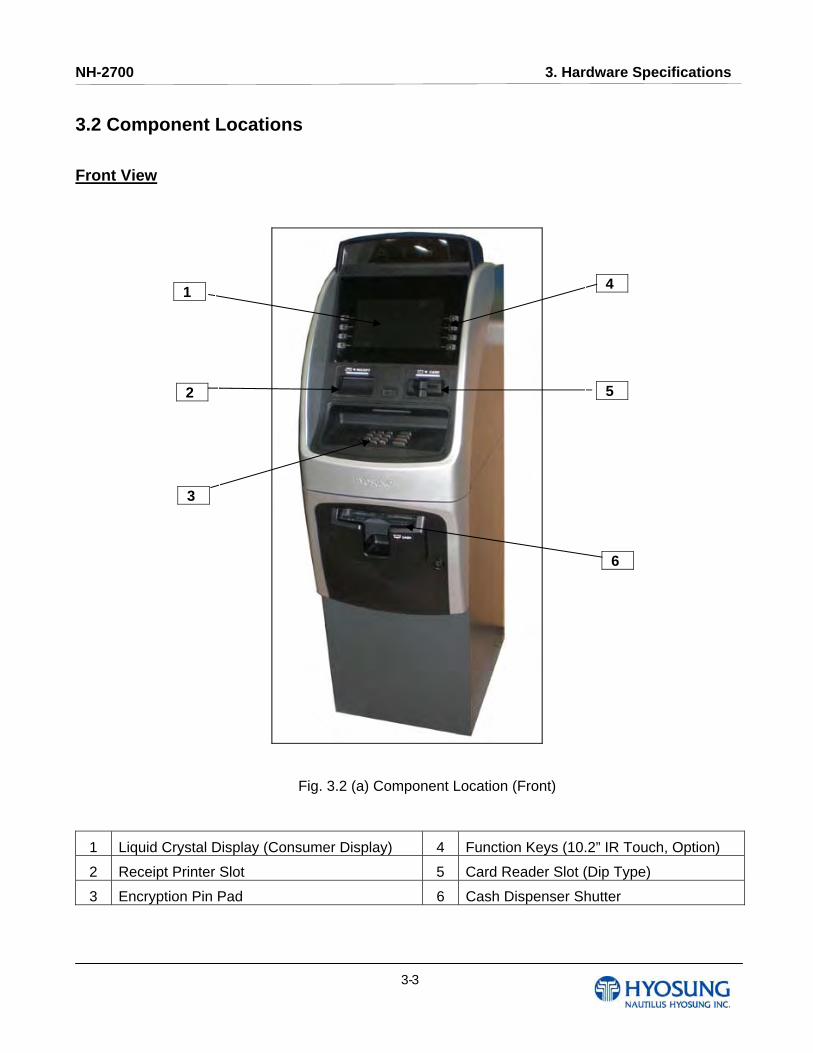
3.2 Component Locations Front View
Fig. 3.2 (a) Component Location (Front)
1 Liquid Crystal Display (Consumer Display) 4 Function Keys (10.2” IR Touch, Option)
2 Receipt Printer Slot 5 Card Reader Slot (Dip Type)
3 Encryption Pin Pad 6 Cash Dispenser Shutter
o2
o3
o4
o5
o6
o1

NH-2700 3. Hardware Specifications
3- 4
Receipt Printer Slot
After the consumer uses the ATM, the receipt printer prints the transaction information on a form. The
ATM presents the form through the receipt printer slot on the upper fascia.
Card Reader Slot
The consumer inserts (to begin transactions) and removes an card from the card reader slot.
Dip Card Reader
The dip card reader is a manually operated device mounted directly to the ATM fascia. The consumer
inserts an ATM card in the card entry slot and then removes the card to begin the transaction. The dip
card reader can read magnetic stripe cards and memory chip cards. The dip card reader cannot
retract, capture, or retain cards.
Cash Dispenser Shutter
When the consumer requests cash, it is presented through the cash dispenser shutter in the lower
fascia.
Consumer keypad (Encryption Pin Pad)
During the transaction sequence, the ATM prompts the consumer to use the consumer keypad to
enter transaction information. The 16-key keypad uses a security module and encrypting PIN pad
technology to secure the information entered by the consumer at the keypad.
Function keypads
The function keypads are made up of four keys mounted on each side of the consumer display. The
consumer selects from the choices shown on the consumer display and presses the corresponding
function key.
Consumer Display
The consumer display welcomes the consumer and provides instructions for performing transactions
at the terminal. An optional touch screen display eliminates the need for function keypads.
NH-2700 3. Hardware Specifications
3- 5
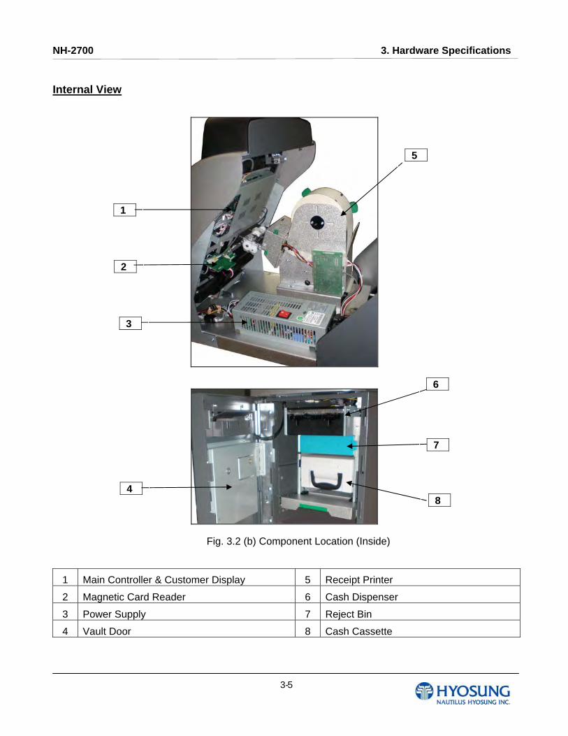
Internal View
Fig. 3.2 (b) Component Location (Inside)
1 Main Controller & Customer Display 5 Receipt Printer
2 Magnetic Card Reader 6 Cash Dispenser
3 Power Supply 7 Reject Bin
4 Vault Door 8 Cash Cassette
o2
o3
o4
o5
o6
o1
o7
o8

NH-2700 3. Hardware Specifications
3- 6
3.3 LCD & Customer Keypad
The customer display welcomes the customer and provides instructions for performing transactions at
the ATM.
During the transaction sequence, the ATM prompts the customer to use the customer keypad to enter
transaction information. The 16-key keypad uses a security module and encryption PIN pad
technology to secure the information entered by the customer at the keypad.
The function keypads are made up of four keys mounted on each side of the customer display. The
customer selects from the choices shown on the consumer display and presses the corresponding
function key.
Fig. 3.3 LCD & Customer Keypad
Basic Specification of LCD
Screen Size : 10.2 ″
Wide TFT LCD
Resolution : 1024 × 600 pixels
4 x 2 Function Keys (Default)
10.2” IR Touch (Option)
Basic Specification of Keypad
10 Alphanumeric ,3,4, ENTER, CLEAR, CANCEL, BLANK Keypads
Customer Display
Encryption PIN Pad Function Keypad
NH-2700 3. Hardware Specifications
3- 7
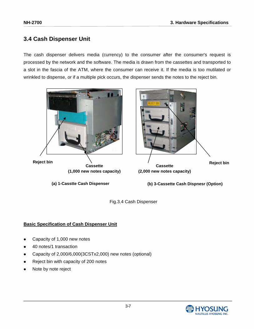
3.4 Cash Dispenser Unit
The cash dispenser delivers media (currency) to the consumer after the consumer's request is
processed by the network and the software. The media is drawn from the cassettes and transported to
a slot in the fascia of the ATM, where the consumer can receive it. If the media is too mutilated or
wrinkled to dispense, or if a multiple pick occurs, the dispenser sends the notes to the reject bin.
Fig.3.4 Cash Dispenser
Basic Specification of Cash Dispenser Unit
Capacity of 1,000 new notes
40 notes/1 transaction
Capacity of 2,000/6,000(3CSTx2,000) new notes (optional)
Reject bin with capacity of 200 notes
Note by note reject
(a) 1-Casstte Cash Dispenser (b) 3-Cassette Cash Dispnesr (Option)
Reject bin Reject bin Cassette
(1,000 new notes capacity) Cassette
(2,000 new notes capacity)
NH-2700 3. Hardware Specifications
3- 8
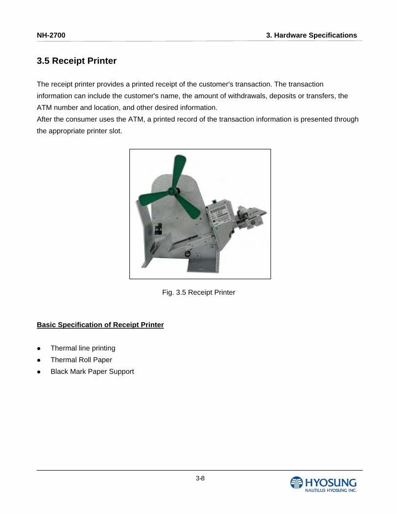
3.5 Receipt Printer The receipt printer provides a printed receipt of the customer's transaction. The transaction
information can include the customer's name, the amount of withdrawals, deposits or transfers, the
ATM number and location, and other desired information.
After the consumer uses the ATM, a printed record of the transaction information is presented through
the appropriate printer slot.
Fig. 3.5 Receipt Printer
Basic Specification of Receipt Printer
Thermal line printing
Thermal Roll Paper
Black Mark Paper Support
NH-2700 3. Hardware Specifications
3- 9
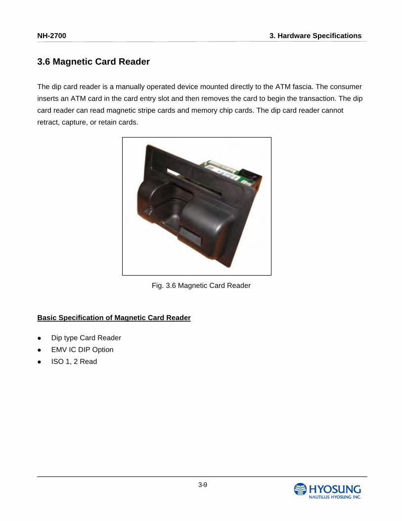
3.6 Magnetic Card Reader The dip card reader is a manually operated device mounted directly to the ATM fascia. The consumer
inserts an ATM card in the card entry slot and then removes the card to begin the transaction. The dip
card reader can read magnetic stripe cards and memory chip cards. The dip card reader cannot
retract, capture, or retain cards.
Fig. 3.6 Magnetic Card Reader
Basic Specification of Magnetic Card Reader
Dip type Card Reader
EMV IC DIP Option
ISO 1, 2 Read
NH-2700 3. Hardware Specifications
3- 10
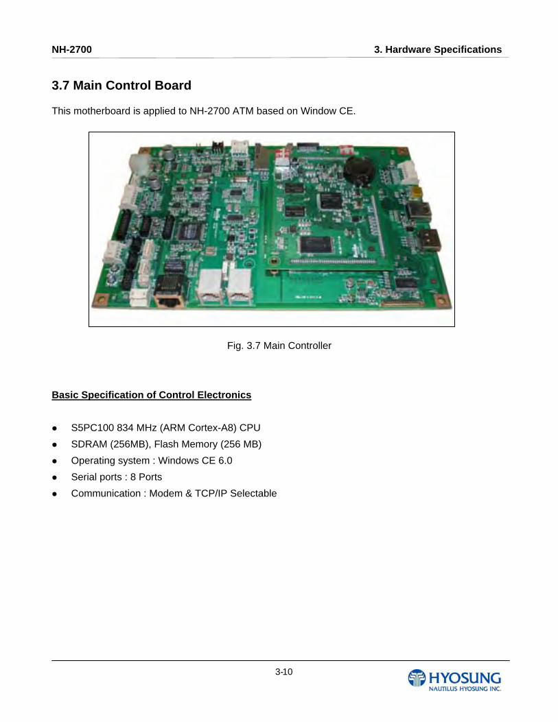
3.7 Main Control Board This motherboard is applied to NH-2700 ATM based on Window CE.
Fig. 3.7 Main Controller
Basic Specification of Control Electronics
S5PC100 834 MHz (ARM Cortex-A8) CPU
SDRAM (256MB), Flash Memory (256 MB)
Operating system : Windows CE 6.0
Serial ports : 8 Ports
Communication : Modem & TCP/IP Selectable
NH-2700 3. Hardware Specifications
3- 11
3.8 Operating Environment
Power Requirements
100W Free Voltage (90~264VAC)
Power Connections
The NH-2700 ATM must be connected to a dedicated power circuit. This circuit must consist of LINE,
NEUTRAL and GROUND leads connected directly to the power circuit breaker panel. This circuit
cannot be shared with any other equipment.
Temperature
In storage : 14°F - 140°F (-10°C ~ 60°C, 15°C/H)
While operating : 41°F - 104°F (5°C ~ 40°C, 10°C/H)
Humidity
In storage : 10% < RH < 90%, Non-Condensed
While operating : 25% < RH < 85%, Non-Condensed

NH-2700 4. Operating Instructions
4 - 1
Chapter 4. Operating Instructions
NH-2700 4. Operating Instructions
4 - 2
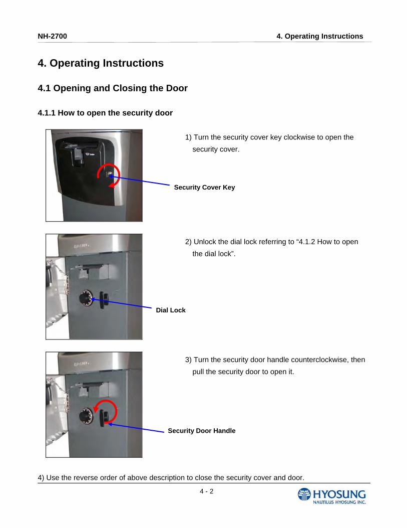
4. Operating Instructions 4.1 Opening and Closing the Door 4.1.1 How to open the security door
1) Turn the security cover key clockwise to open the
security cover.
2) Unlock the dial lock referring to “4.1.2 How to open
the dial lock”.
3) Turn the security door handle counterclockwise, then
pull the security door to open it.
4) Use the reverse order of above description to close the security cover and door.
Dial Lock
Security Door Handle
Security Cover Key
NH-2700 4. Operating Instructions
4 - 3
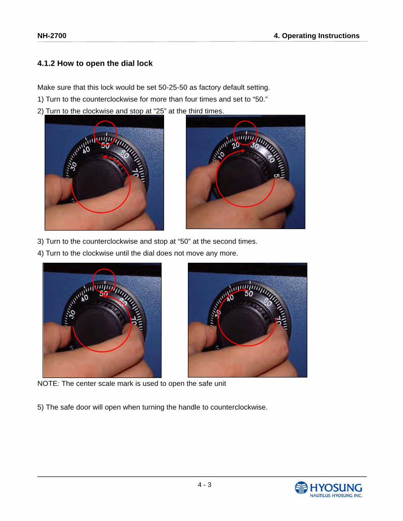
4.1.2 How to open the dial lock
Make sure that this lock would be set 50-25-50 as factory default setting.
1) Turn to the counterclockwise for more than four times and set to “50.”
2) Turn to the clockwise and stop at “25” at the third times.
3) Turn to the counterclockwise and stop at “50” at the second times.
4) Turn to the clockwise until the dial does not move any more.
NOTE: The center scale mark is used to open the safe unit
5) The safe door will open when turning the handle to counterclockwise.
NH-2700 4. Operating Instructions
4 - 4
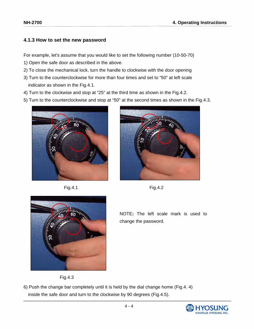
4.1.3 How to set the new password
For example, let's assume that you would like to set the following number (10-50-70)
1) Open the safe door as described in the above.
2) To close the mechanical lock, turn the handle to clockwise with the door opening
3) Turn to the counterclockwise for more than four times and set to “50” at left scale
indicator as shown in the Fig.4.1.
4) Turn to the clockwise and stop at “25” at the third time as shown in the Fig.4.2.
5) Turn to the counterclockwise and stop at “50” at the second times as shown in the Fig.4.3.
6) Push the change bar completely until it is held by the dial change home (Fig.4. 4)
inside the safe door and turn to the clockwise by 90 degrees (Fig.4.5).
Fig.4.1 Fig.4.2
NOTE: The left scale mark is used to
change the password.
Fig.4.3

NH-2700 4. Operating Instructions
4 - 5
.
Fig.4.4 Fig.4.5
7) Turn to the counterclockwise more than four times and position at left scale indicator to “10”
(target number to change).
8) Turn to the clockwise for three times and position the scale to “50” (target number to change).
9) Turn to the counterclockwise for two times and position the scale to “70” (target number to
change).
Fig.4.6 Fig.4.7
NH-2700 4. Operating Instructions
4 - 6
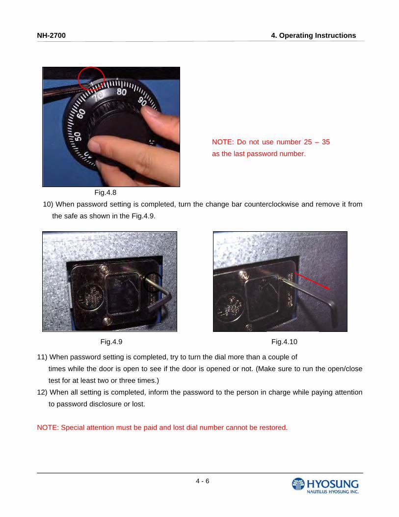
Fig.4.8
10) When password setting is completed, turn the change bar counterclockwise and remove it from
the safe as shown in the Fig.4.9.
11) When password setting is completed, try to turn the dial more than a couple of
times while the door is open to see if the door is opened or not. (Make sure to run the open/close
test for at least two or three times.)
12) When all setting is completed, inform the password to the person in charge while paying attention
to password disclosure or lost.
NOTE: Special attention must be paid and lost dial number cannot be restored.
Fig.4.9 Fig.4.10
NOTE: Do not use number 25 – 35
as the last password number.
NH-2700 4. Operating Instructions
4 - 7
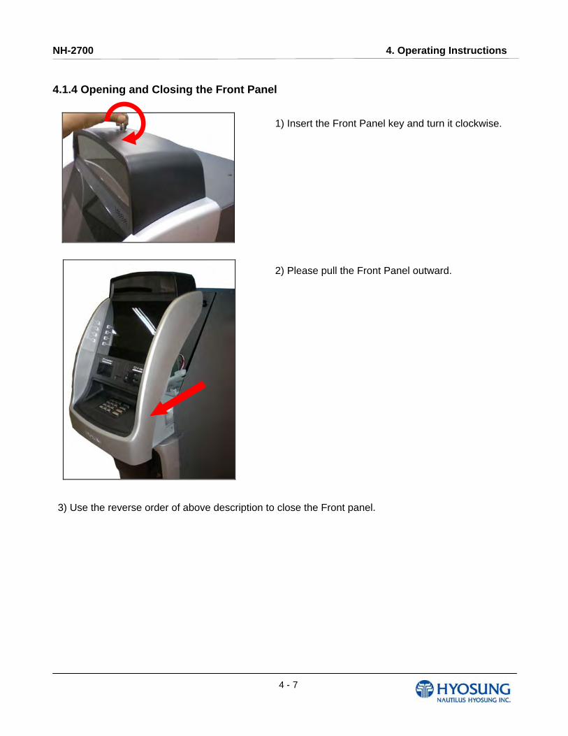
4.1.4 Opening and Closing the Front Panel
1) Insert the Front Panel key and turn it clockwise.
2) Please pull the Front Panel outward.
3) Use the reverse order of above description to close the Front panel.

NH-2700 4. Operating Instructions
4 - 8
Option A : Electronic Lock
How to open the electronic lock
1) Enter the password for the electronic
combination lock.
(Default setting value : 123456)
2) Turn the electronic lock to the 90 degree
clockwise as shown in left picture
3) Then turn the handle clockwise and open the
safe door.
How to close the electronic combination lock
1) Close the Safe Door and turn the handle
counterclockwise. The Safe Door will be locked
in 5~6 seconds automatically.
2) Turn the electronic lock to the 90 degree
counterclockwise as shown in left picture.
3) Then the safe door will be closed.
How to set the new password
1) Enter 0-0-0-0-0-0, six (6) zeros, into the Electronic Lock keypad.
2) Enter in the old combination once.
3) Enter in the new combination twice. Combinations must be six digits in length.
4) If a mistake is made wait thirty (30) seconds and repeat steps 1. - 3.
5) Test lock operation several times before closing the door.
● Valid Code Entry - Double signal after valid six (6) digit code is entered.
● Invalid Code Entry - Triple signal and old code is still valid.
NOTE: The Electronic Lock will signal three (3) times if the new combination is invalid and the old
combination has been retained

NH-2700 4. Operating Instructions
4 - 9
LOW BATTERY WARNING
● Repeated audio and visual signal (LED flashing and repeated
beeping) during opening indicates battery low.
AUDIO AND VISUAL SIGNAL
● Double signal (LED flashes and unit beeps) indicates entry is valid or accepted.
● Triple signal indicates invalid or not accepted.
WRONG TRY PENALTY
● Entry of four (4) consecutive invalid codes starts a 5-minute delay period.
- LED flashed red at five (5) second intervals.
● At the end of the delay period, two more consecutive invalid codes will restart an
additional 5-minute delay period.
[WARNING!] ALWAYS PERFORM THIS OPERATION WITH THE DOOR OPEN
BATTERY LOW WARNING
● Repeated beeping during an opening indicates that the battery is low and needs immediate
replacement.
● Uses one (1) 9-Volt Alkaline Battery. LA GARD recommends the use of Duracell™ or Everready™
Alkaline batteries. If battery is depleted and will not allow lock to open, simply follow instructions
below.
CHANGING YOUR BATTERY
NOTE: Some manufacturers use a small screw to secure the battery compartment
cover to the keypad housing. If your model has this screw, it must be removed first before following
the steps listed below.
1) Remove black plastic battery compartment cover (located at the bottom of the keypad) by gently
pulling downward on it’s handle.
NH-2700 4. Operating Instructions
4 - 10
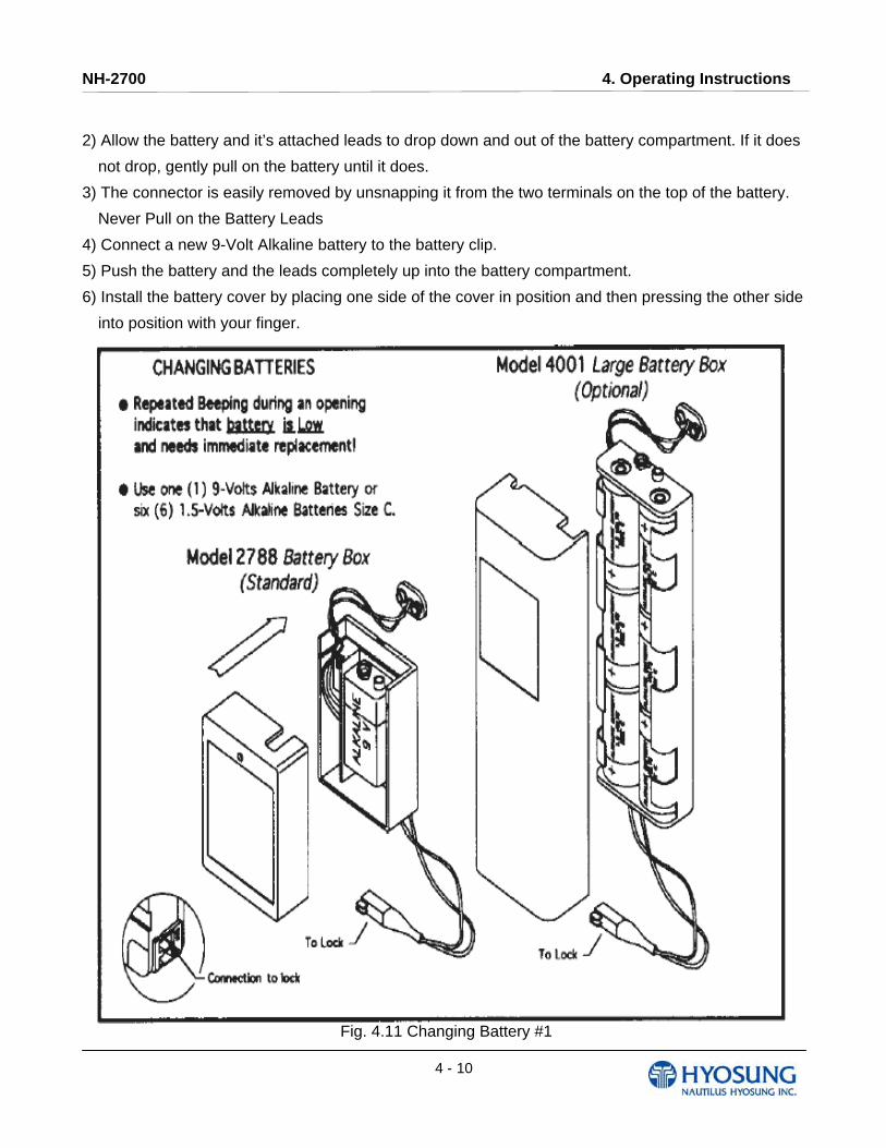
2) Allow the battery and it’s attached leads to drop down and out of the battery compartment. If it does
not drop, gently pull on the battery until it does.
3) The connector is easily removed by unsnapping it from the two terminals on the top of the battery.
Never Pull on the Battery Leads
4) Connect a new 9-Volt Alkaline battery to the battery clip.
5) Push the battery and the leads completely up into the battery compartment.
6) Install the battery cover by placing one side of the cover in position and then pressing the other side
into position with your finger.
Fig. 4.11 Changing Battery #1
NH-2700 4. Operating Instructions
4 - 11
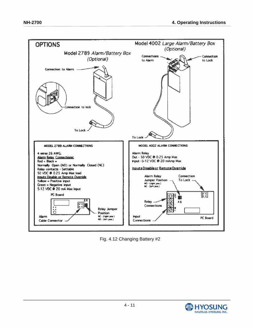
Fig. 4.12 Changing Battery #2
NH-2700 4. Operating Instructions
4 - 12
Option B. Cencon Lock
Initial Operating Instructions
Each lock is shipped from the factory in Shelved Mode, operating on a standard combination (50-25-
50). The “one time only” combination does not function when the lock is in this condition. The correct
opening procedure for a new lock is :
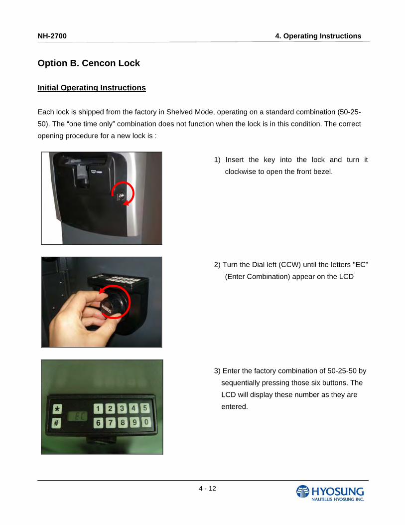
1) Insert the key into the lock and turn it
clockwise to open the front bezel.
2) Turn the Dial left (CCW) until the letters "EC”
(Enter Combination) appear on the LCD
3) Enter the factory combination of 50-25-50 by
sequentially pressing those six buttons. The
LCD will display these number as they are
entered.
NH-2700 4. Operating Instructions
4 - 13
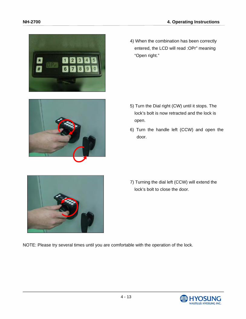
4) When the combination has been correctly
entered, the LCD will read :OPr” meaning
“Open right.”
5) Turn the Dial right (CW) until it stops. The
lock’s bolt is now retracted and the lock is
open.
6) Turn the handle left (CCW) and open the
door.
7) Turning the dial left (CCW) will extend the
lock’s bolt to close the door.
NOTE: Please try several times until you are comfortable with the operation of the lock.
NH-2700 4. Operating Instructions
4 - 14
Change Shelved Mode Combination
For System 2000 Locks with a code level of 71, or greater, you may change the Shelved Mode
combination. You may change the default Factory Combination of 50-25-50 to a new combination to
be used while the lock is still in Shelved Mode. Once you have changed the combination for the first
time, you may want to change the combination again to a different Shelved Mode combination. You
can even change it back to the Factory combination of 50-25-50
Required Items: Change Key, Current Shelved Mode Combination
NOTE: You can only change the Shelved Mode combination while operating in Shelved Mode. Once a
lock is “activated” in any mode, the Shelved Mode combination returns to the Factory Default of 50-25-
50
To change the Shelved Mode combination:
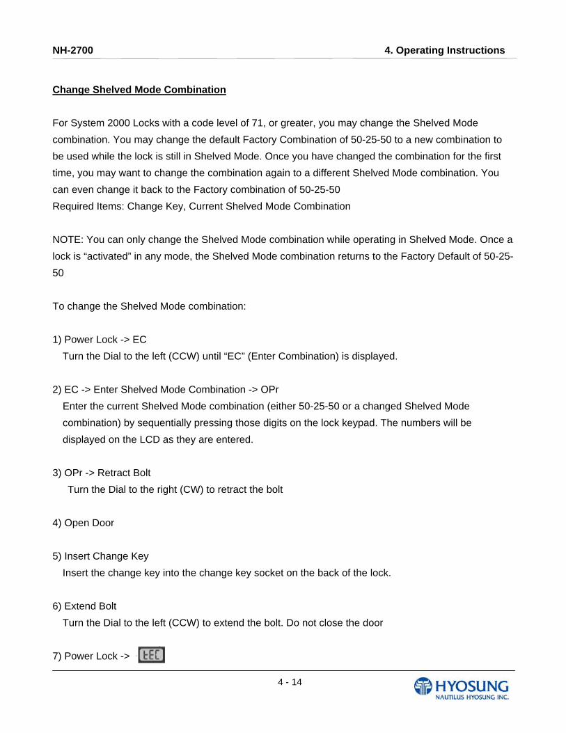
1) Power Lock -> EC
Turn the Dial to the left (CCW) until “EC” (Enter Combination) is displayed.
2) EC -> Enter Shelved Mode Combination -> OPr
Enter the current Shelved Mode combination (either 50-25-50 or a changed Shelved Mode
combination) by sequentially pressing those digits on the lock keypad. The numbers will be
displayed on the LCD as they are entered.
3) OPr -> Retract Bolt
Turn the Dial to the right (CW) to retract the bolt
4) Open Door
5) Insert Change Key
Insert the change key into the change key socket on the back of the lock.
6) Extend Bolt
Turn the Dial to the left (CCW) to extend the bolt. Do not close the door
7) Power Lock ->
NH-2700 4. Operating Instructions
4 - 15
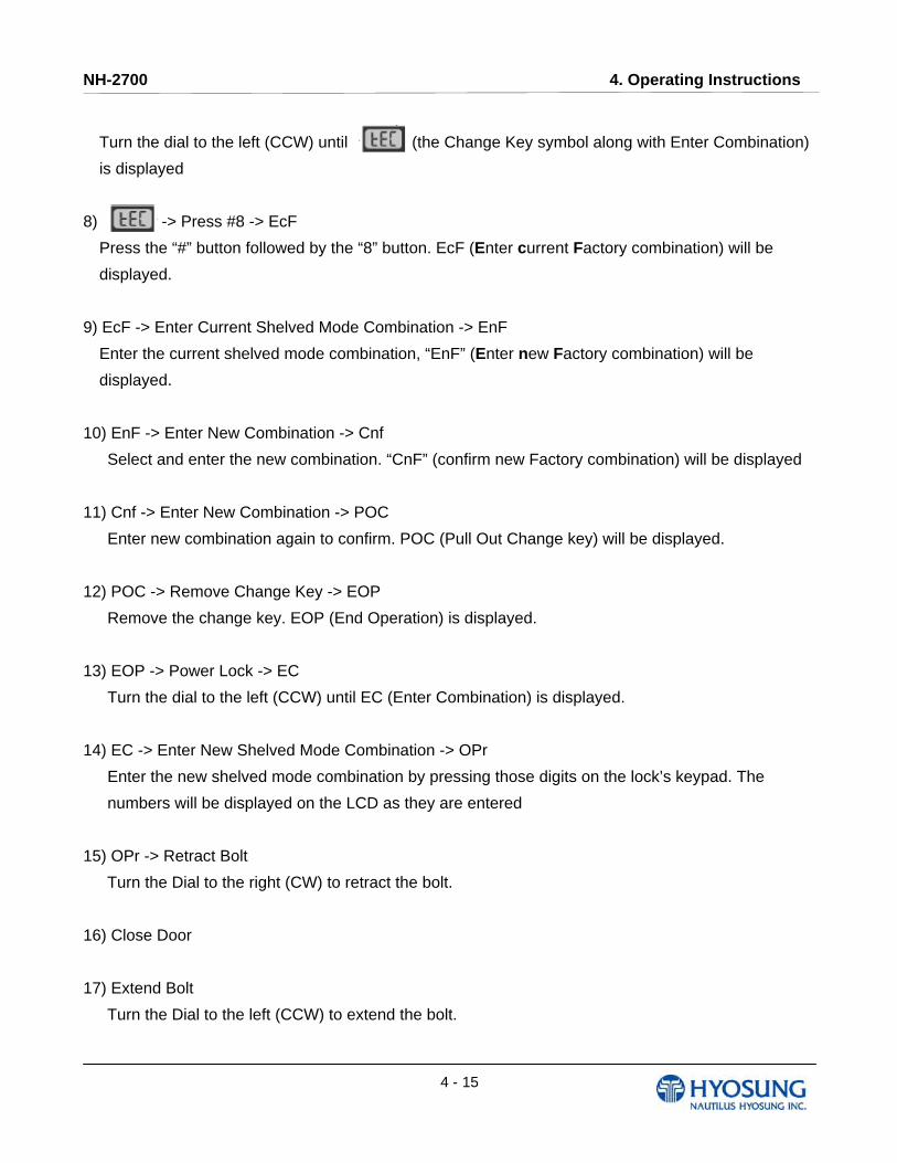
Turn the dial to the left (CCW) until (the Change Key symbol along with Enter Combination)
is displayed
8) -> Press #8 -> EcF
Press the “#” button followed by the “8” button. EcF (Enter current Factory combination) will be
displayed.
9) EcF -> Enter Current Shelved Mode Combination -> EnF
Enter the current shelved mode combination, “EnF” (Enter new Factory combination) will be
displayed.
10) EnF -> Enter New Combination -> Cnf
Select and enter the new combination. “CnF” (confirm new Factory combination) will be displayed
11) Cnf -> Enter New Combination -> POC
Enter new combination again to confirm. POC (Pull Out Change key) will be displayed.
12) POC -> Remove Change Key -> EOP
Remove the change key. EOP (End Operation) is displayed.
13) EOP -> Power Lock -> EC
Turn the dial to the left (CCW) until EC (Enter Combination) is displayed.
14) EC -> Enter New Shelved Mode Combination -> OPr
Enter the new shelved mode combination by pressing those digits on the lock’s keypad. The
numbers will be displayed on the LCD as they are entered
15) OPr -> Retract Bolt
Turn the Dial to the right (CW) to retract the bolt.
16) Close Door
17) Extend Bolt
Turn the Dial to the left (CCW) to extend the bolt.

NH-2700 4. Operating Instructions
4 - 16
4.2 Cash Dispenser 4.2.1 Bill Conditions
Acceptable condition
1) Bill which is very clean and can readily be recognized as a true bill
2) Bill has sufficient life or sizing to be handled easily
3) Bill which can be manually held straightly when one end is held by a hand and the bill is slightly
curved vertically
NH-2700 4. Operating Instructions
4 - 17
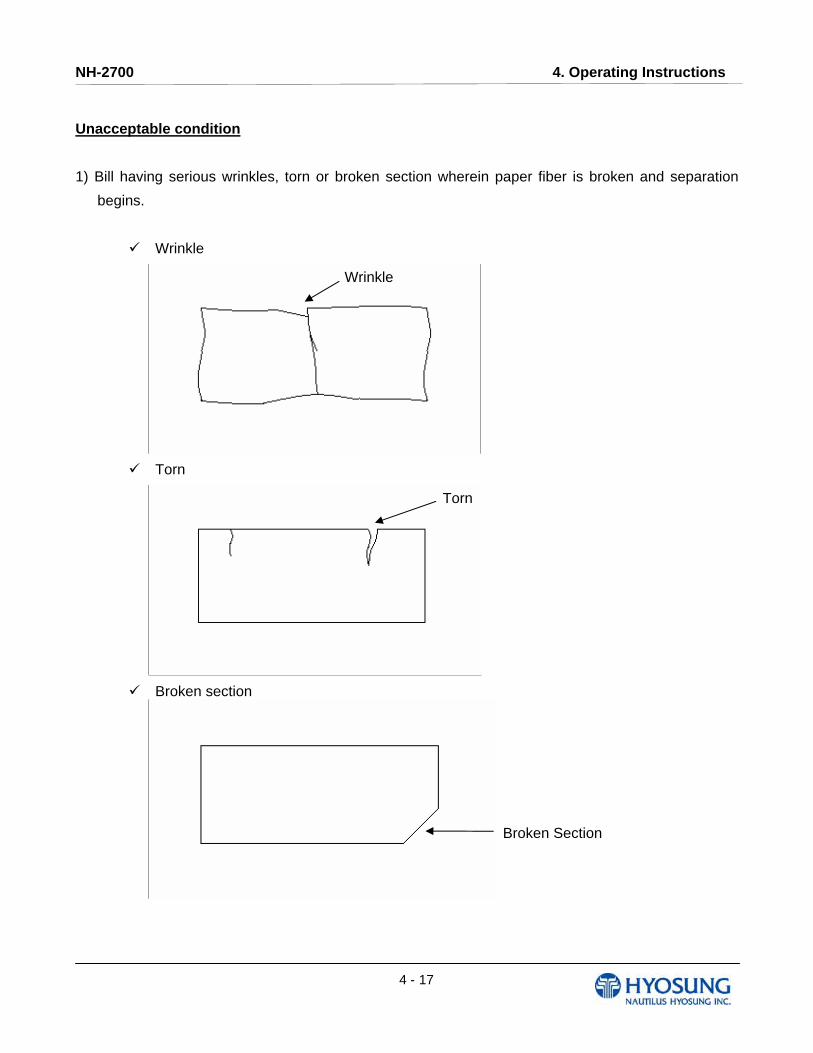
Unacceptable condition
1) Bill having serious wrinkles, torn or broken section wherein paper fiber is broken and separation
begins.
Wrinkle
Torn
Broken section
Wrinkle
Torn
Broken Section

NH-2700 4. Operating Instructions
4 - 18
2) Bill having adequate life or sizing, but stained seriously
3) Bill with holes (Perforated bill)
4) Bill ragged and cannot be held straightly when one end is supported by a hand
Stained
Hole
20mm
35mm
When the bill is held by 20mm and the straightness of the bill is 35mm or less, it cannot be used
NH-2700 4. Operating Instructions
4 - 19
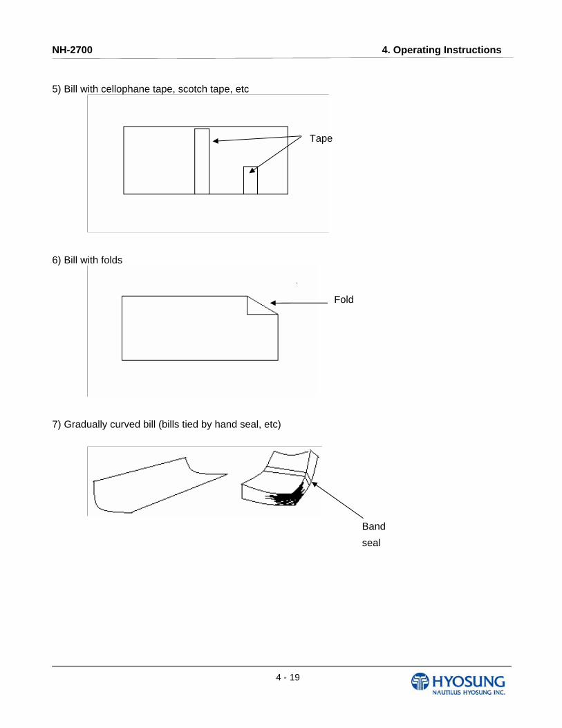
5) Bill with cellophane tape, scotch tape, etc
6) Bill with folds
7) Gradually curved bill (bills tied by hand seal, etc)
Tape
Fold
Band
seal
NH-2700 4. Operating Instructions
4 - 20
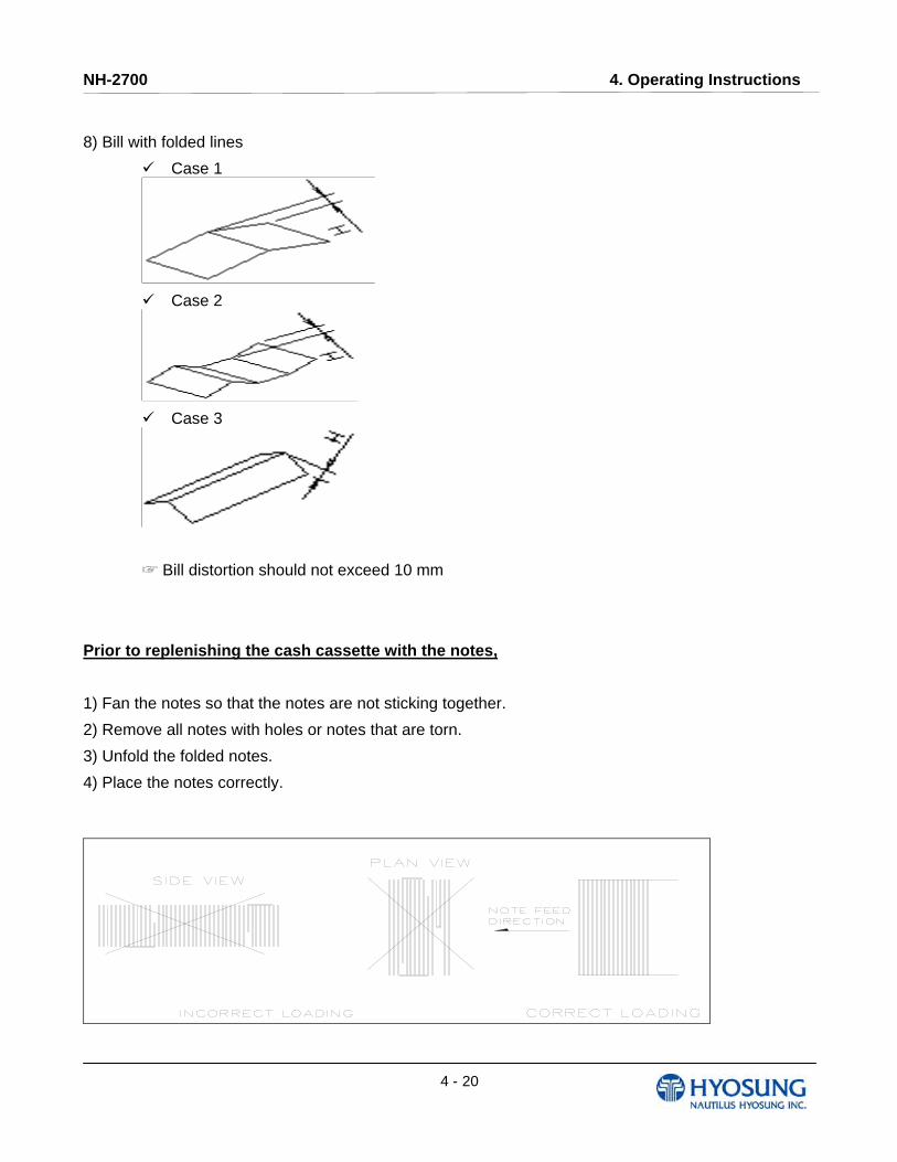
8) Bill with folded lines
Case 1
Case 2
Case 3
☞ Bill distortion should not exceed 10 mm
Prior to replenishing the cash cassette with the notes,
1) Fan the notes so that the notes are not sticking together.
2) Remove all notes with holes or notes that are torn.
3) Unfold the folded notes.
4) Place the notes correctly.
NH-2700 4. Operating Instructions
4 - 21
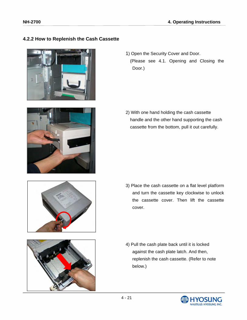
4.2.2 How to Replenish the Cash Cassette
1) Open the Security Cover and Door.
(Please see 4.1. Opening and Closing the
Door.)
2) With one hand holding the cash cassette
handle and the other hand supporting the cash
cassette from the bottom, pull it out carefully.
3) Place the cash cassette on a flat level platform
and turn the cassette key clockwise to unlock
the cassette cover. Then lift the cassette
cover.
4) Pull the cash plate back until it is locked
against the cash plate latch. And then,
replenish the cash cassette. (Refer to note
below.)

NH-2700 4. Operating Instructions
4 - 22
5) After replenishing the cash cassette, release
the cash plate from the cash plate latch and
allow it gradually to take up its position behind
the notes.
6) After closing the cassette cover, turn the key counterclockwise
7) With one hand holding the cash cassette
handle and the other hand supporting the cash
cassette from the bottom, place the cash
cassette carefully on the set guide of the Cash
Dispensing Unit and push it in until it is locked
in place.
8) And then close the security door.
NH-2700 4. Operating Instructions
4 - 23
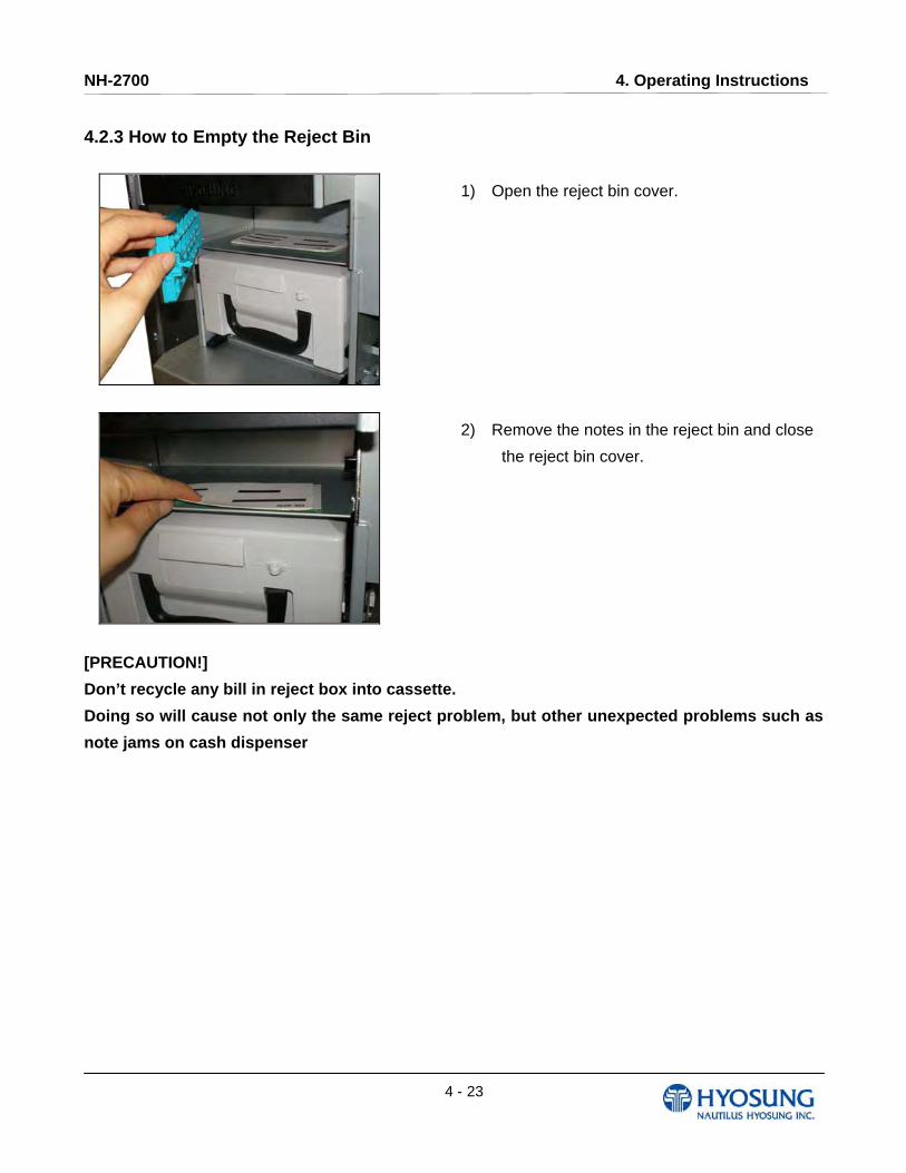
4.2.3 How to Empty the Reject Bin
1) Open the reject bin cover.
2) Remove the notes in the reject bin and close
the reject bin cover.
[PRECAUTION!]
Don’t recycle any bill in reject box into cassette.
Doing so will cause not only the same reject problem, but other unexpected problems such as
note jams on cash dispenser
NH-2700 4. Operating Instructions
4 - 24
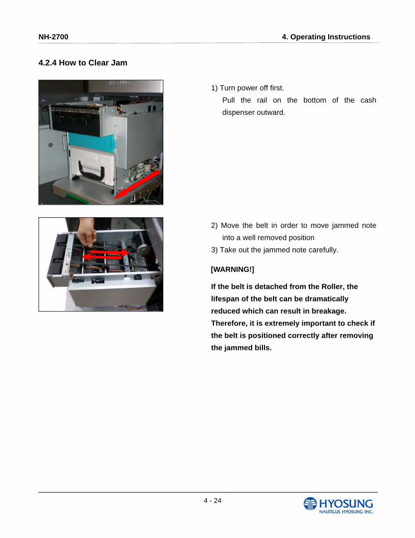
4.2.4 How to Clear Jam
1) Turn power off first.
Pull the rail on the bottom of the cash
dispenser outward.
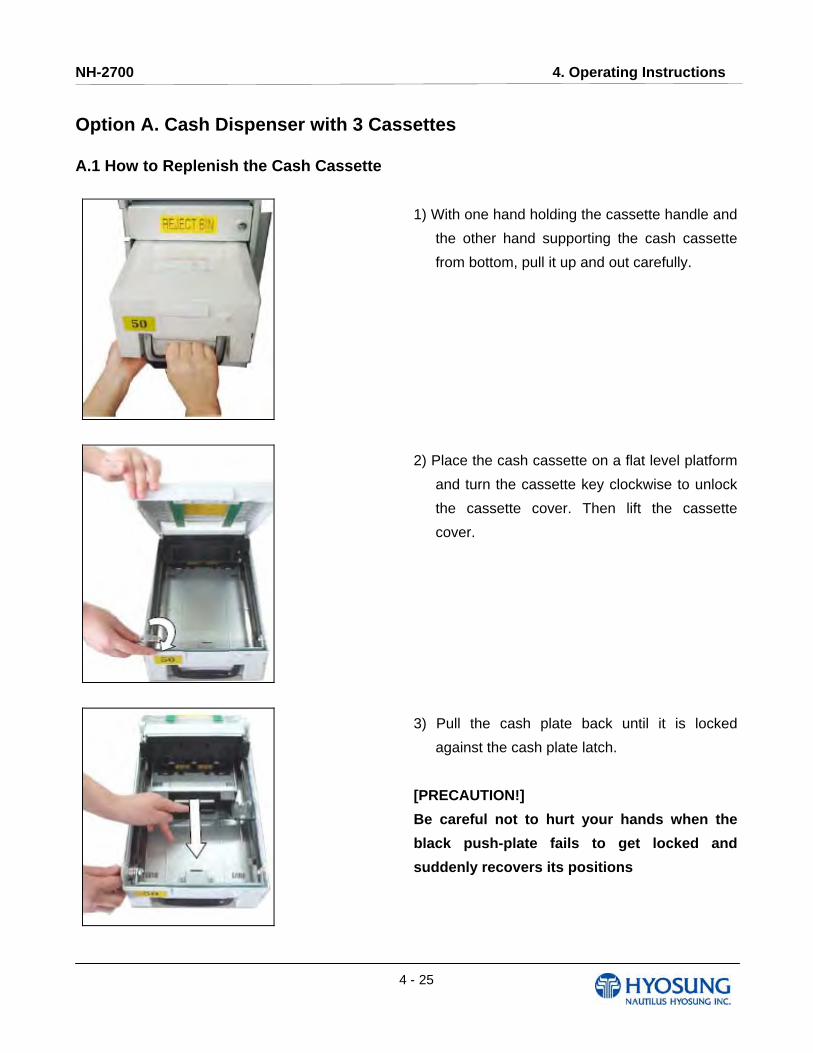
2) Move the belt in order to move jammed note
into a well removed position
3) Take out the jammed note carefully.
[WARNING!]
If the belt is detached from the Roller, the
lifespan of the belt can be dramatically
reduced which can result in breakage.
Therefore, it is extremely important to check if
the belt is positioned correctly after removing
the jammed bills.
NH-2700 4. Operating Instructions
4 - 25
Option A. Cash Dispenser with 3 Cassettes
A.1 How to Replenish the Cash Cassette
1) With one hand holding the cassette handle and
the other hand supporting the cash cassette
from bottom, pull it up and out carefully.
2) Place the cash cassette on a flat level platform
and turn the cassette key clockwise to unlock
the cassette cover. Then lift the cassette
cover.
3) Pull the cash plate back until it is locked
against the cash plate latch.
[PRECAUTION!]
Be careful not to hurt your hands when the
black push-plate fails to get locked and
suddenly recovers its positions
NH-2700 4. Operating Instructions
4 - 26
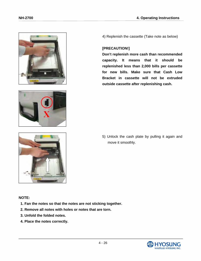
4) Replenish the cassette (Take note as below)
[PRECAUTION!]
Don’t replenish more cash than recommended
capacity. It means that it should be
replenished less than 2,000 bills per cassette
for new bills. Make sure that Cash Low
Bracket in cassette will not be extruded
outside cassette after replenishing cash.
5) Unlock the cash plate by pulling it again and
move it smoothly.
NOTE:
1. Fan the notes so that the notes are not sticking together.
2. Remove all notes with holes or notes that are torn.
3. Unfold the folded notes.
4. Place the notes correctly.

NH-2700 4. Operating Instructions
4 - 27
6) Close the cassette cover and turn the cassette
key counterclockwise until it is locked.
Remove the key when it is locked.
7) With one hand holding the cassette handle and
the other hand supporting the cassette from the
bottom, place the cassette carefully on the set
guide of the CDU and push it in until it is locked
in place.
NH-2700 4. Operating Instructions
4 - 28
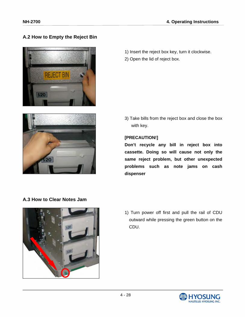
A.2 How to Empty the Reject Bin
1) Insert the reject box key, turn it clockwise.
2) Open the lid of reject box.
3) Take bills from the reject box and close the box
with key.
[PRECAUTION!]
Don’t recycle any bill in reject box into
cassette. Doing so will cause not only the
same reject problem, but other unexpected
problems such as note jams on cash
dispenser
A.3 How to Clear Notes Jam
1) Turn power off first and pull the rail of CDU
outward while pressing the green button on the
CDU.

NH-2700 4. Operating Instructions
4 - 29
2) Turn the pulley located in left upper in order to
move jammed note into a well removed
position.
3) Take out the jammed note carefully.
4) Remove the cash cassettes to check whether
there is any jammed note inside of CDU body.
If so, remove the jammed note from it.
[WARNING!]
If the belt is detached from the Roller, the
lifespan of the belt can be dramatically
reduced which can result in breakage.
Therefore, it is extremely important to check if
the belt is positioned correctly after removing
the jammed bills.

NH-2700 4. Operating Instructions
4 - 30
4.3 Receipt Printer 4.3.1 Receipt Paper
Specifications
Item Specifications Remark
Paper Type Thermal Roll Paper Paper detects heat.
Paper Width 79.5±0.5mm
Paper Exterior Ø180
Paper basis Weight 55±3 g/㎡
Paper Thickness 58±4 ㎛
Print Color Black
Type of Paper Setting Semi-Auto loading
Roll appearance
(Thermal printing side is OUTSIDE,
NOT INSIDE of roll paper)
Beginning and ending edge of the
paper should be that of the printing
specifications.
NH-2700 4. Operating Instructions
4 - 31
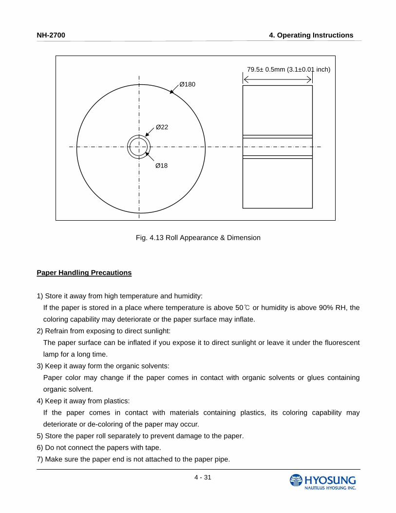
Fig. 4.13 Roll Appearance & Dimension
Paper Handling Precautions
1) Store it away from high temperature and humidity:
If the paper is stored in a place where temperature is above 50 or humidity is above 90% RH, the ℃
coloring capability may deteriorate or the paper surface may inflate.
2) Refrain from exposing to direct sunlight:
The paper surface can be inflated if you expose it to direct sunlight or leave it under the fluorescent
lamp for a long time.
3) Keep it away form the organic solvents:
Paper color may change if the paper comes in contact with organic solvents or glues containing
organic solvent.
4) Keep it away from plastics:
If the paper comes in contact with materials containing plastics, its coloring capability may
deteriorate or de-coloring of the paper may occur.
5) Store the paper roll separately to prevent damage to the paper.
6) Do not connect the papers with tape.
7) Make sure the paper end is not attached to the paper pipe.
Ø180
Ø22
Ø18
79.5± 0.5mm (3.1±0.01 inch)
NH-2700 4. Operating Instructions
4 - 32
8) Make sure the paper is rolled evenly.
9) Miscellaneous:
If the paper comes in contact with carbon copy paper or if the paper surface is scratched with a
metallic object, de-coloring may occur.
4.3.2 How to load the receipt paper
Prior to loading the receipt paper, the following must be kept in mind.
NOTE:
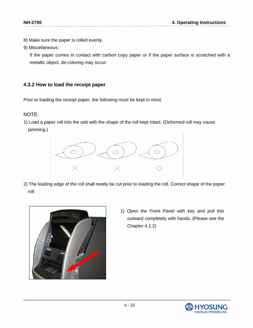
1) Load a paper roll into the unit with the shape of the roll kept intact. (Deformed roll may cause
jamming.)
2) The leading edge of the roll shall neatly be cut prior to loading the roll. Correct shape of the paper
roll
1) Open the Front Panel with key and pull this
outward completely with hands. (Please see the
Chapter 4.1.2)
NH-2700 4. Operating Instructions
4 - 33
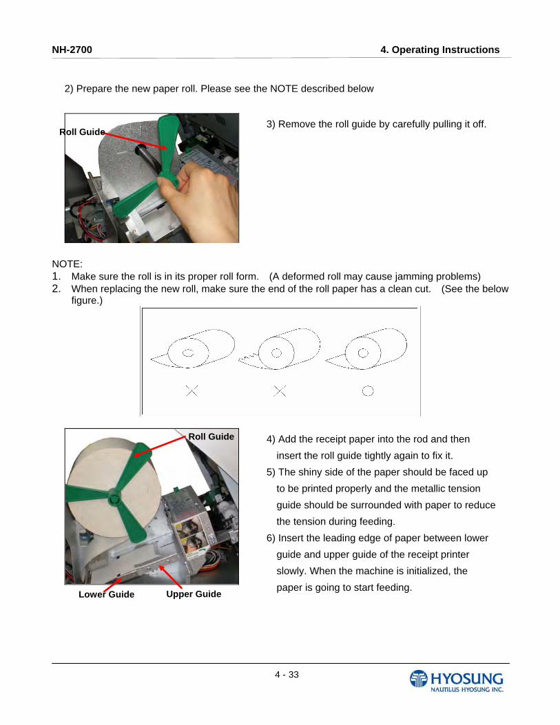
2) Prepare the new paper roll. Please see the NOTE described below
3) Remove the roll guide by carefully pulling it off.
NOTE: 1. Make sure the roll is in its proper roll form. (A deformed roll may cause jamming problems) 2. When replacing the new roll, make sure the end of the roll paper has a clean cut. (See the below
figure.)
4) Add the receipt paper into the rod and then
insert the roll guide tightly again to fix it.
5) The shiny side of the paper should be faced up
to be printed properly and the metallic tension
guide should be surrounded with paper to reduce
the tension during feeding.
6) Insert the leading edge of paper between lower
guide and upper guide of the receipt printer
slowly. When the machine is initialized, the
paper is going to start feeding.
Roll Guide
Roll Guide
Upper Guide Lower Guide
NH-2700 4. Operating Instructions
4 - 34
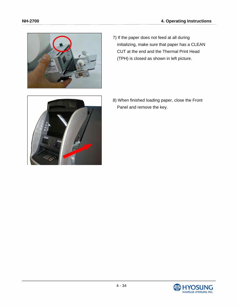
7) If the paper does not feed at all during
initializing, make sure that paper has a CLEAN
CUT at the end and the Thermal Print Head
(TPH) is closed as shown in left picture.
8) When finished loading paper, close the Front
Panel and remove the key.

NH-2700 4. Operating Instructions
4 - 35
NOTE: THE BASIC MECHANISM OF RECEIPT PRINTER
NH-2700 4. Operating Instructions
4 - 36
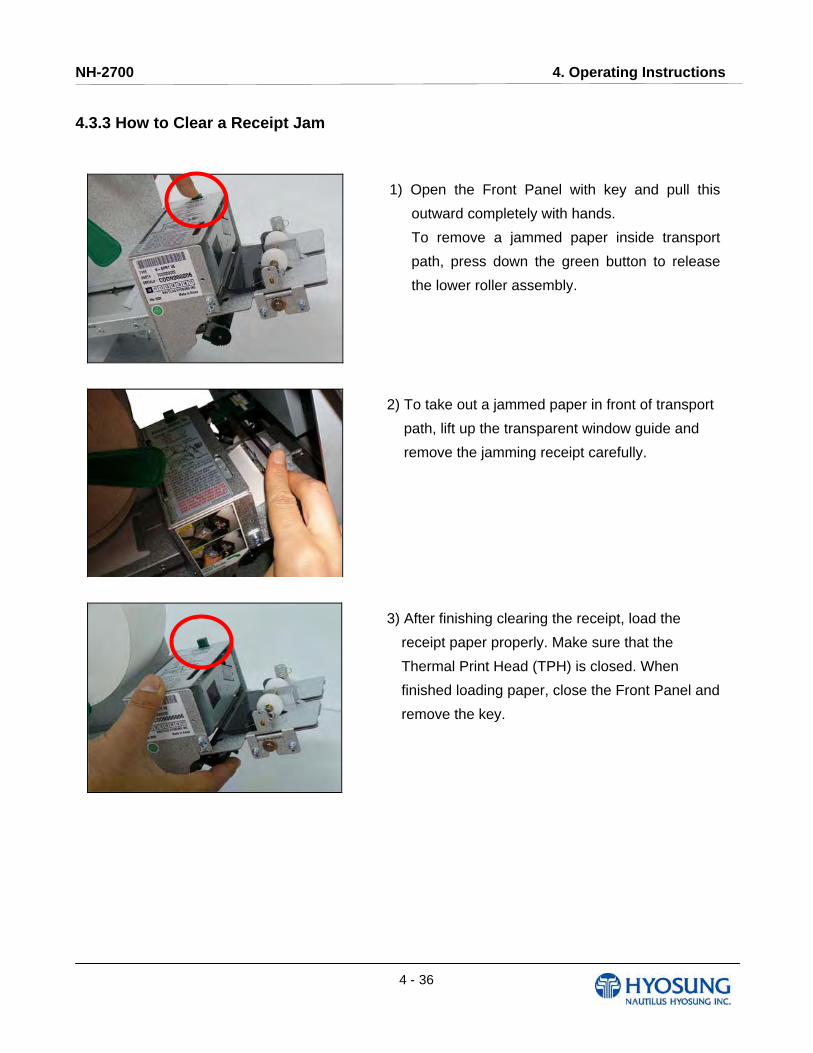
4.3.3 How to Clear a Receipt Jam
1) Open the Front Panel with key and pull this
outward completely with hands.
To remove a jammed paper inside transport
path, press down the green button to release
the lower roller assembly.
2) To take out a jammed paper in front of transport
path, lift up the transparent window guide and
remove the jamming receipt carefully.
3) After finishing clearing the receipt, load the
receipt paper properly. Make sure that the
Thermal Print Head (TPH) is closed. When
finished loading paper, close the Front Panel and
remove the key.

NH-2700 4. Operating Instructions
4 - 37
4.4 Magnetic Card Specifications
Item ISO Card (Unit : Inch)
Length
Card Bending
Magnetic Stripe
Position
NH-2700 5. Operator Function
5- 1
Chapter 5. Operator Function

NH-2700 5. Operator Function
5- 2
5.1 BASIC SYSTEM OPERATION 5.1.1 PASSWORD FOR ENTERING SUPERVISOR MODE
- Location of Function Key on ATM –
- Main Screen on SPL of Rear Type Machine –
To enter Supervisor mode press the ENTER, CLEAR, CANCEL, 1, 2 and 3 keys in order.
(In case of Rear Type Machine, press the IN SUPERVISOR button)
The default password is “555555”(6 digits). The default password is changeable in Supervisor mode.
F1
F3
F5
F7
F2
F4
F6
F8
NH-2700 5. Operator Function
5- 3
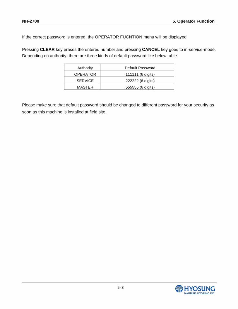
If the correct password is entered, the OPERATOR FUCNTION menu will be displayed.
Pressing CLEAR key erases the entered number and pressing CANCEL key goes to in-service-mode.
Depending on authority, there are three kinds of default password like below table.
Please make sure that default password should be changed to different password for your security as
soon as this machine is installed at field site.
Authority Default Password
OPERATOR 111111 (6 digits)
SERVICE 222222 (6 digits)
MASTER 555555 (6 digits)
NH-2700 5. Operator Function
5- 4
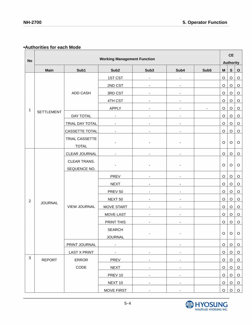
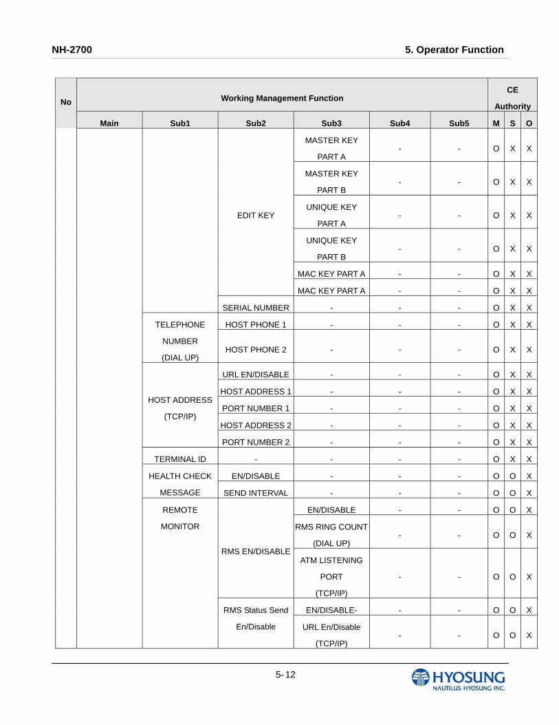
▪Authorities for each Mode
Working Management Function CE
AuthorityNo
Main Sub1 Sub2 Sub3 Sub4 Sub5 M S O
1ST CST - - O O O
2ND CST - - O O O
3RD CST - - O O O
4TH CST - - O O O
ADD CASH
APPLY - - - O O O
DAY TOTAL - - - O O O
TRIAL DAY TOTAL - - - O O O
CASSETTE TOTAL - - - O O O
1 SETTLEMENT
TRIAL CASSETTE
TOTAL - - - O O O
CLEAR JOURNAL - - - O O O
CLEAR TRANS.
SEQUENCE NO. - - - O O O
PREV - - O O O
NEXT - - O O O
PREV 50 - - O O O
NEXT 50 - - O O O
MOVE START - - O O O
MOVE LAST - - O O O
PRINT THIS - - O O O
VIEW JOURNAL
SEARCH
JOURNAL - - O O O
PRINT JOURNAL - - O O O
2 JOURNAL
LAST X PRINT - - - O O O
PREV - - O O O
NEXT - - O O O
PREV 10 - - O O O
NEXT 10 - - O O O
3 REPORT ERROR
CODE
MOVE FIRST - - O O O

NH-2700 5. Operator Function
5- 5
Working Management Function CE
AuthorityNo
Main Sub1 Sub2 Sub3 Sub4 Sub5 M S O
MOVE LAST - - - O O O
PRINT THIS - - - O O O
SEARCH
ERROR CODE - - - O O O
SW VERSION - - - - O O O
PRINT ALL SETUP - - - - O O O
PRINT - - - O O O
CLEAR - - - O O O
PREV - - - O O O
ERROR
SUMMARY
NEXT - - - O O O
PRINT - - - O O OREJECT
ANALYSIS CLEAR - - - O O O
INITIALIZE - - - - O O X
RECEIPT
PRINTER - - - - O O X
CASH DISPENSER - - - - O O X
MODEM
(DIAL UP) - - - O O X
TCP/IP
(TCP/IP) - - - - O O X
CARD SCAN - - - - O O X
CDU SENSOR - - O O XSENSOR
SPR SENSOR - - O O X
ALL FLICKER - - O O X
EPP FLICKER - - O O X
CDU FLICKER - - O O X
SPR FLICKER - - O O X
AUXILIARY UNIT
FLICKER
MCU FLICKER - - O O X
4 DIAGNOSTICS
AGING - - - - O O X
5 CUSTOMER
SETUP
CHANGE
MESSAGE
WELCOM
MESSAGE - - - O O O
NH-2700 5. Operator Function
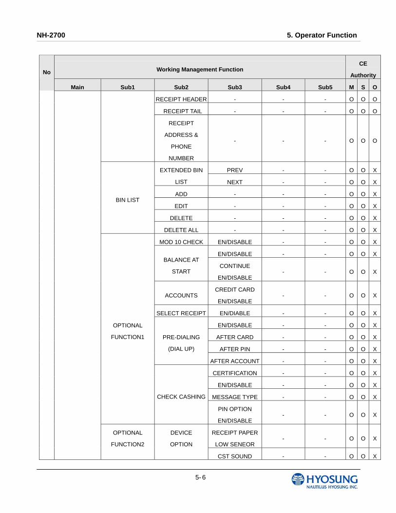
5- 6
Working Management Function CE
AuthorityNo
Main Sub1 Sub2 Sub3 Sub4 Sub5 M S O
RECEIPT HEADER - - - O O O
RECEIPT TAIL - - - O O O
RECEIPT
ADDRESS &
PHONE
NUMBER
- - - O O O
PREV - - O O X EXTENDED BIN
LIST NEXT - - O O X
ADD - - - O O X
EDIT - - - O O X
DELETE - - - O O X
BIN LIST
DELETE ALL - - - O O X
MOD 10 CHECK EN/DISABLE - - O O X
EN/DISABLE - - O O XBALANCE AT
START CONTINUE
EN/DISABLE - - O O X
ACCOUNTS CREDIT CARD
EN/DISABLE - - O O X
SELECT RECEIPT EN/DIABLE - - O O X
EN/DISABLE - - O O X
AFTER CARD - - O O X
AFTER PIN - - O O X
PRE-DIALING
(DIAL UP)
AFTER ACCOUNT - - O O X
CERTIFICATION - - O O X
EN/DISABLE - - O O X
MESSAGE TYPE - - O O X
OPTIONAL
FUNCTION1
CHECK CASHING
PIN OPTION
EN/DISABLE - - O O X
RECEIPT PAPER
LOW SENEOR - - O O X
OPTIONAL
FUNCTION2
DEVICE
OPTION
CST SOUND - - O O X
NH-2700 5. Operator Function
5- 7
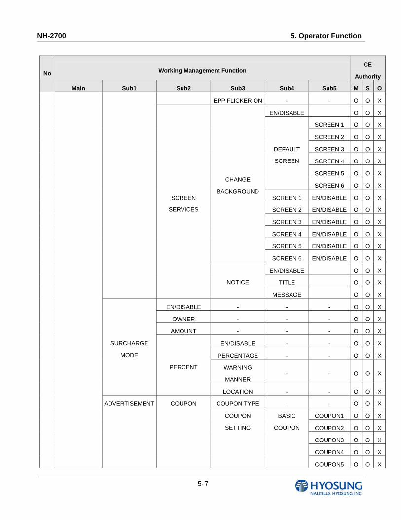
Working Management Function CE
AuthorityNo
Main Sub1 Sub2 Sub3 Sub4 Sub5 M S O
EPP FLICKER ON - - O O X
EN/DISABLE O O X
SCREEN 1 O O X
SCREEN 2 O O X
SCREEN 3 O O X
SCREEN 4 O O X
SCREEN 5 O O X
DEFAULT
SCREEN
SCREEN 6 O O X
SCREEN 1 EN/DISABLE O O X
SCREEN 2 EN/DISABLE O O X
SCREEN 3 EN/DISABLE O O X
SCREEN 4 EN/DISABLE O O X
SCREEN 5 EN/DISABLE O O X
CHANGE
BACKGROUND
SCREEN 6 EN/DISABLE O O X
EN/DISABLE O O X
TITLE O O X
SCREEN
SERVICES
NOTICE
MESSAGE O O X
EN/DISABLE - - - O O X
OWNER - - - O O X
AMOUNT - - - O O X
EN/DISABLE - - O O X
PERCENTAGE - - O O X
WARNING
MANNER - - O O X
SURCHARGE
MODE
PERCENT
LOCATION - - O O X
COUPON TYPE - - O O X
COUPON1 O O X
COUPON2 O O X
COUPON3 O O X
COUPON4 O O X
ADVERTISEMENT COUPON
COUPON
SETTING
BASIC
COUPON
COUPON5 O O X
NH-2700 5. Operator Function
5- 8
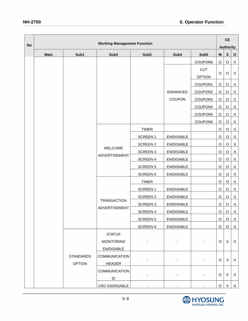
Working Management Function CE
AuthorityNo
Main Sub1 Sub2 Sub3 Sub4 Sub5 M S O
COUPON6 O O X
CUT
OPTION O O X
COUPON1 O O X
COUPON2 O O X
COUPON3 O O X
COUPON4 O O X
COUPON5 O O X
ENHANCED
COUPON
COUPON6 O O X
TIMER O O X
SCREEN 1 EN/DISABLE O O X
SCREEN 2 EN/DISABLE O O X
SCREEN 3 EN/DISABLE O O X
SCREEN 4 EN/DISABLE O O X
SCREEN 5 EN/DISABLE O O X
WELCOME
ADVERTISEMENT
SCREEN 6 EN/DISABLE O O X
TIMER O O X
SCREEN 1 EN/DISABLE O O X
SCREEN 2 EN/DISABLE O O X
SCREEN 3 EN/DISABLE O O X
SCREEN 4 EN/DISABLE O O X
SCREEN 5 EN/DISABLE O O X
TRANSACTION
ADVERTISEMENT
SCREEN 6 EN/DISABLE O O X
STATUS
MONITORING
EN/DISABLE
- - - O X X
COMMUNICATION
HEADER - - - O X X
COMMUNICATION
ID - - - O X X
STANDARD3
OPTION
CRC EN/DISABLE - - - O X X

NH-2700 5. Operator Function
5- 9
Working Management Function CE
AuthorityNo
Main Sub1 Sub2 Sub3 Sub4 Sub5 M S O
TERMINAL
STATUS
EN/DISABLE
O X X
HOST ERROR
EN/DISABLE O X X
STANDARD1
OPTION
REVERSAL
REASON
EN/DISABLE
O X X
DIALUP - - O X X COMMUNICATION
TCP/IP - - O X X
GENERAL - - O X X
EOT OPTIONAL - - O X X
NO EOT
REQUIRED - - O X X EOT/ENQ OPTION
NO ENQ
REQUIRED - - O X X
STANDARD 1 - - O X X
STANDARD 2 - - O X X
STANDARD 3 - - O X X
MESSAGE
FORMAT
EPS - - O X X
VISA FRAMED - - O X X
STANDARD - - O X X
ACK
CONTROLLED - - O X X
TCP/IP TYPE
SSL EN/DISABLE - - O X X
SELECT
PROCESSOR
REVERSAL
RETRY COUNT- - - O X X
YEAR - - - O O O
MONTH - - - O O O
DAY - - - O O O
6 SYSTEM
SETUP
DATE & TIME
HOUR - - - O O O
NH-2700 5. Operator Function
5- 10
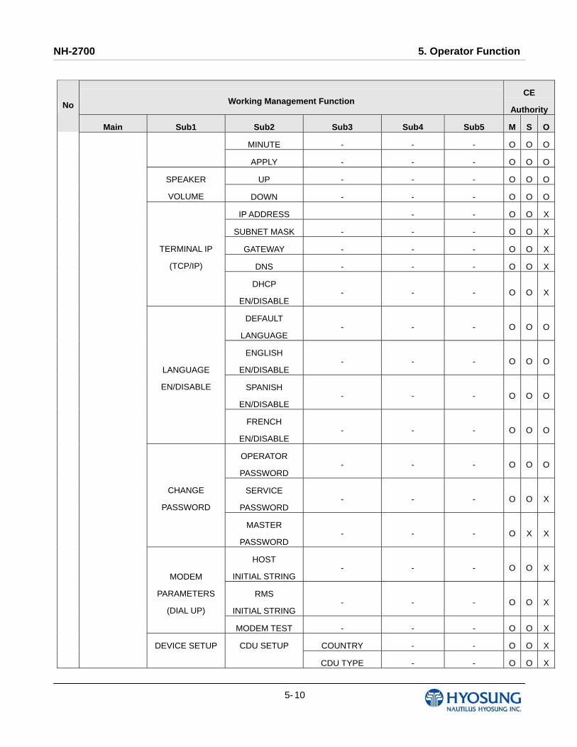
Working Management Function CE
AuthorityNo
Main Sub1 Sub2 Sub3 Sub4 Sub5 M S O
MINUTE - - - O O O
APPLY - - - O O O
UP - - - O O OSPEAKER
VOLUME DOWN - - - O O O
IP ADDRESS - - O O X
SUBNET MASK - - - O O X
GATEWAY - - - O O X
DNS - - - O O X
TERMINAL IP
(TCP/IP)
DHCP
EN/DISABLE - - - O O X
DEFAULT
LANGUAGE - - - O O O
ENGLISH
EN/DISABLE - - - O O O
SPANISH
EN/DISABLE - - - O O O
LANGUAGE
EN/DISABLE
FRENCH
EN/DISABLE - - - O O O
OPERATOR
PASSWORD - - - O O O
SERVICE
PASSWORD - - - O O X
CHANGE
PASSWORD
MASTER
PASSWORD - - - O X X
HOST
INITIAL STRING- - - O O X
RMS
INITIAL STRING- - - O O X
MODEM
PARAMETERS
(DIAL UP)
MODEM TEST - - - O O X
COUNTRY - - O O XDEVICE SETUP CDU SETUP
CDU TYPE - - O O X

NH-2700 5. Operator Function
5- 11
Working Management Function CE
AuthorityNo
Main Sub1 Sub2 Sub3 Sub4 Sub5 M S O
CASSETTE
VOLUME - - O O X
EXECUTE - - O O X
CALRIBRATION
(Rear Type Only) O O X
TOUCH
VIBRATION
(Touch Type Only)
EN/DISABLE O O X
SOFTWARE
UPDATE - - - O O O
REBOOT - - - O O O
BACKUP ALL
JOURNAL TO USB- - - O O O
FROM - - O O O
TO - - O O O
BACKUP
JOURNAL BY
DATE TO USB SEARCH - - O O O
BACKUP LOG TO
USB - - - O O O
CLEAR ALL - - O X X
CLEAR SETTING - - O X X
CLEAR JOURNAL - - O X X
CLEAR TRANS
SEQUENCE
NUMBER
- - O X X
CLEAR NVRAM
CLEAR LOG - - O X X
BACK NVRAM O X X
SYSTEM
CONTROL
RESTORE NVRAM O X X
KEY MODE - - - O X X
KEY INDEX - - - O X X
7 HOST SETUP KEY
MANAGEMENT
CHECK KEY - - - O X X
NH-2700 5. Operator Function
5- 12
Working Management Function CE
AuthorityNo
Main Sub1 Sub2 Sub3 Sub4 Sub5 M S O
MASTER KEY
PART A - - O X X
MASTER KEY
PART B - - O X X
UNIQUE KEY
PART A - - O X X
UNIQUE KEY
PART B - - O X X
MAC KEY PART A - - O X X
EDIT KEY
MAC KEY PART A - - O X X
SERIAL NUMBER - - - O X X
HOST PHONE 1 - - - O X XTELEPHONE
NUMBER
(DIAL UP) HOST PHONE 2 - - - O X X
URL EN/DISABLE - - - O X X
HOST ADDRESS 1 - - - O X X
PORT NUMBER 1 - - - O X X
HOST ADDRESS 2 - - - O X X
HOST ADDRESS
(TCP/IP)
PORT NUMBER 2 - - - O X X
TERMINAL ID - - - - O X X
EN/DISABLE - - - O O XHEALTH CHECK
MESSAGE SEND INTERVAL - - - O O X
EN/DISABLE - - O O X
RMS RING COUNT
(DIAL UP) - - O O X
RMS EN/DISABLEATM LISTENING
PORT
(TCP/IP)
- - O O X
EN/DISABLE- - - O O X
REMOTE
MONITOR
RMS Status Send
En/Disable URL En/Disable
(TCP/IP) - - O O X

NH-2700 5. Operator Function
5- 13
Working Management Function CE
AuthorityNo
Main Sub1 Sub2 Sub3 Sub4 Sub5 M S O
PHONE NUMBER1
(DIAL UP) - - O O X
PHONE NUMBER2
(DIAL UP) - - O O X
INTERVAL - - O O X
RMS ADDRESS
(TCP/IP) - - O O X
RMS LISTENING
PORT
(TCP/IP)
- - O O X
RMS PASSWORD - - - O O X
ROUTING ID - - - - O X X
EN/DISABLE - - - O O O
TOTAL TYPE - - - O O O
HOUR - - - O O OAUTO DAY TOTAL
MINUTE - - - O O O
DISPENSE LIMIT - - - - O O X
LB 0 - - - O O X
LB 1 - - - O O X
LB 2 - - - O O X
RB 0 - - - O O X
RB 1 - - - O O X
FAST CASH
RB 2 - - - O O X
LOW CURRENCY
CHECK
EN/DISABLE
- - - - O O X
1ST CASSETTE - - - O X X
2ND CASSETTE - - - O X X
3RD CASSETTE - - - O X X
8 TRANSACTION
SETUP
DENOMINATION
4TH CASSETTE - - - O X X
9 IN SERVICE - - - - - O O O
NH-2700 5. Operator Function
5- 14
Working Management Function CE
AuthorityNo
Main Sub1 Sub2 Sub3 Sub4 Sub5 M S O
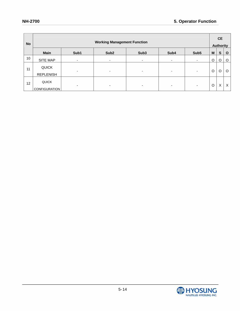
10 SITE MAP - - - - - O O O
11 QUICK
REPLENISH - - - - - O O O
12 QUICK
CONFIGURATION - - - - - O X X
NH-2700 5. Operator Function
5- 15
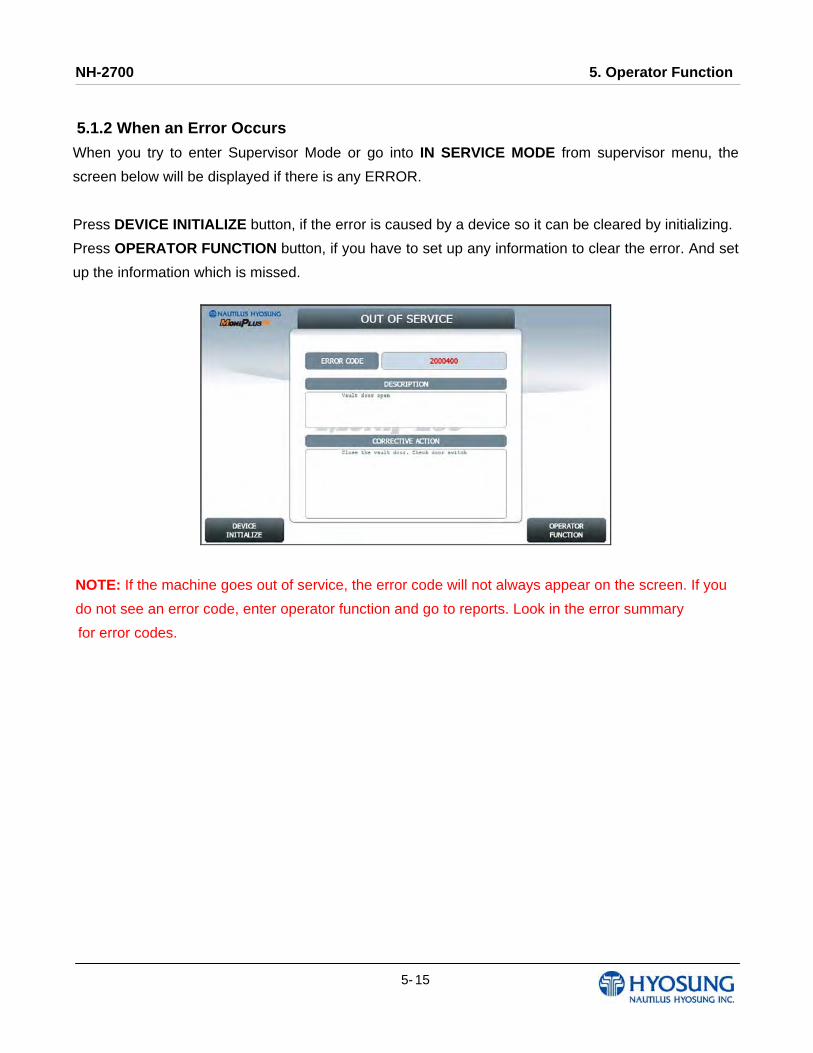
5.1.2 When an Error Occurs
When you try to enter Supervisor Mode or go into IN SERVICE MODE from supervisor menu, the
screen below will be displayed if there is any ERROR.
Press DEVICE INITIALIZE button, if the error is caused by a device so it can be cleared by initializing.
Press OPERATOR FUNCTION button, if you have to set up any information to clear the error. And set
up the information which is missed.
NOTE: If the machine goes out of service, the error code will not always appear on the screen. If you
do not see an error code, enter operator function and go to reports. Look in the error summary
for error codes.

NH-2700 5. Operator Function
5- 16
5.1.3 How to Use KeyPad (Function Key Type)
This section explains the basic operation of the KeyPad.
[Default KeyPad Character Table Screen]
Shift Status 0 1 2 3 4 5 6 7 8 9
NUMBER -
0
(
)
1
[
]
2
{
}
3
<
>
4
,
.
5
!
$
6
‘
“
7
%
*
8
:
;
9
?
/
UPPER
+
-
=
Space
Q
Z
A
B
C
D
E
F
G
H
I
J
K
L
M
N
O
P
R
S
T
U
V
W
X
Y ALPHA
LOWER
+
-
=
Space
q
z
a
b
c
d
e
f
g
h
i
j
k
l
m
n
o
p
r
s
t
u
v
w
x
y
F1
TABLE
F3
- The character on the current cursor position on the screen wil be
selected
NH-2700 5. Operator Function
5- 17
How to Enter the Character A. The Keypad Character Table will appear on the bottom of the screen in all keypad input screens.
B. F1 key gives the option for ALPHA or NUMBER, Table mode. Default is NUMBER.
C. F3 key gives the option for Upper or Lowercase characters. It is valid only in the ALPHA mode.
Default is Uppercase.
D. The input of characters is limited to the space provided.
E. Key can be changed whenever you press it to choose proper character. For example, when key “1” is pressed once it is “SPACE”, pressed twice it is “Q”, pressed third time it is “Z” in case of the Alpha mode. When the desired character is selected, press ENTER.
F. ◀,▶ keys move the cursor position in the ALPHA or NUMBER mode. In the TABLE mode ◀,▶ keys are used to select the character.
G. F2 key is used to clear the whole screen and returns the cursor to its initial position.
H. F4 key and CLEAR key in pinpad are used to clear the current line.
I. F5 key is used to save the current changes.
J. F6 key and CANCEL key in pinpad are used to exit. (If you didn’t press F5 key after changing, the changes will be ignored.)
K. F7 key is used to move the cursor position UP.
L. F8 key is used to move the cursor position DOWN.
NH-2700 5. Operator Function
5- 18
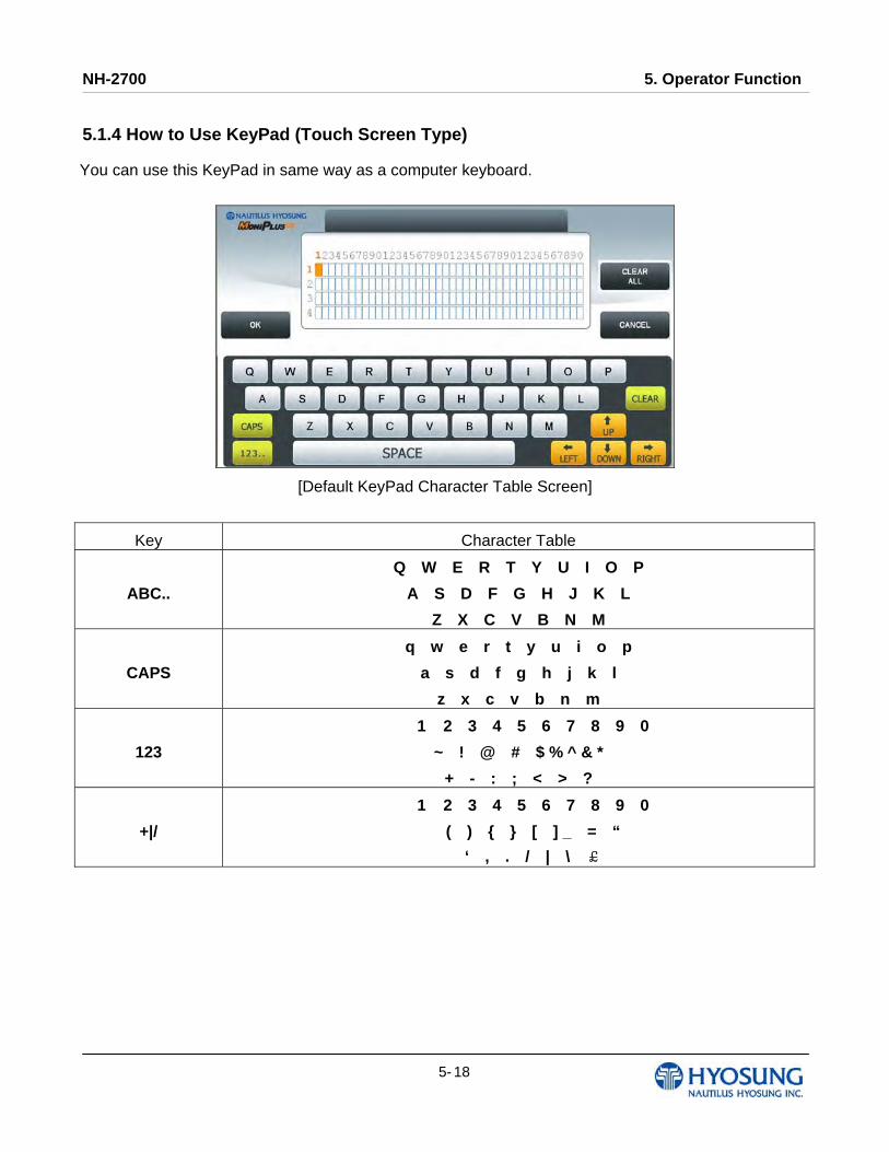
5.1.4 How to Use KeyPad (Touch Screen Type)
You can use this KeyPad in same way as a computer keyboard.
[Default KeyPad Character Table Screen]
Key Character Table
ABC..
Q W E R T Y U I O P
A S D F G H J K L
Z X C V B N M
CAPS
q w e r t y u i o p
a s d f g h j k l
z x c v b n m
123
1 2 3 4 5 6 7 8 9 0
~ ! @ # $ % ^ & *
+ - : ; < > ?
+|/
1 2 3 4 5 6 7 8 9 0
( ) { } [ ] _ = “
‘ , . / | \ £
NH-2700 5. Operator Function
5- 19
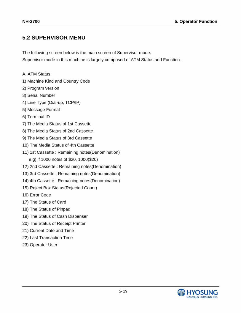
5.2 SUPERVISOR MENU The following screen below is the main screen of Supervisor mode.
Supervisor mode in this machine is largely composed of ATM Status and Function.
A. ATM Status
1) Machine Kind and Country Code
2) Program version
3) Serial Number
4) Line Type (Dial-up, TCP/IP)
5) Message Format
6) Terminal ID
7) The Media Status of 1st Cassette
8) The Media Status of 2nd Cassette
9) The Media Status of 3rd Cassette
10) The Media Status of 4th Cassette
11) 1st Cassette : Remaining notes(Denomination)
e.g) if 1000 notes of $20, 1000($20)
12) 2nd Cassette : Remaining notes(Denomination)
13) 3rd Cassette : Remaining notes(Denomination)
14) 4th Cassette : Remaining notes(Denomination)
15) Reject Box Status(Rejected Count)
16) Error Code
17) The Status of Card
18) The Status of Pinpad
19) The Status of Cash Dispenser
20) The Status of Receipt Printer
21) Current Date and Time
22) Last Transaction Time
23) Operator User

NH-2700 5. Operator Function
5- 20
B. Functions
1) IN SERVICE
2) SITE MAP
3) QUICK REPLENISH
4) QUICK CONFIGURATION
F1) SETTLEMENT
F2) CUSTOMER SETUP
F3) JOURNAL
F4) SYSTEM SETUP
F5) REPORT
F6) HOST SETUP
F7) DIAGNOSTICS
F8) TRANSACTION SETUP
In order to move to the in-service mode, press the 1 or CANCEL key in pinpad.
In order to reset terminal error, press the CLEAR key in pinpad.
[Function Key Type] [Touch Type]
NH-2700 5. Operator Function
5- 21
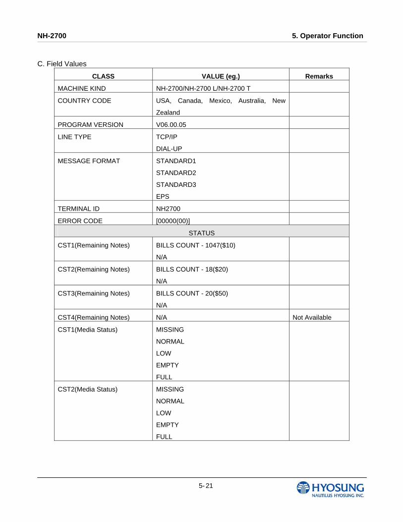
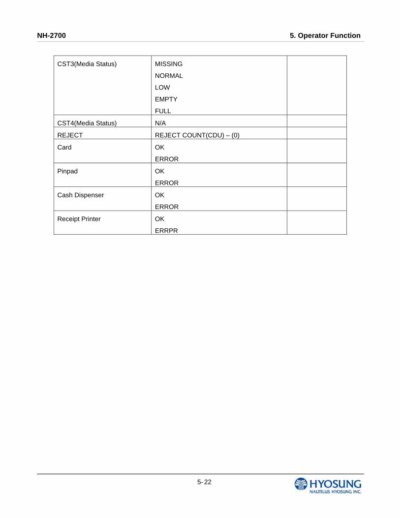
C. Field Values
CLASS VALUE (eg.) Remarks
MACHINE KIND NH-2700/NH-2700 L/NH-2700 T
COUNTRY CODE USA, Canada, Mexico, Australia, New
Zealand
PROGRAM VERSION V06.00.05
LINE TYPE TCP/IP
DIAL-UP
MESSAGE FORMAT STANDARD1
STANDARD2
STANDARD3
EPS
TERMINAL ID NH2700
ERROR CODE [00000(00)]
STATUS
CST1(Remaining Notes) BILLS COUNT - 1047($10)
N/A
CST2(Remaining Notes) BILLS COUNT - 18($20)
N/A
CST3(Remaining Notes) BILLS COUNT - 20($50)
N/A
CST4(Remaining Notes) N/A Not Available
CST1(Media Status) MISSING
NORMAL
LOW
EMPTY
FULL
CST2(Media Status) MISSING
NORMAL
LOW
EMPTY
FULL
NH-2700 5. Operator Function
5- 22
CST3(Media Status) MISSING
NORMAL
LOW
EMPTY
FULL
CST4(Media Status) N/A
REJECT REJECT COUNT(CDU) – (0)
Card OK
ERROR
Pinpad OK
ERROR
Cash Dispenser OK
ERROR
Receipt Printer OK
ERRPR

NH-2700 5. Operator Function
5- 23
5.3 SETTLEMENT This menu contains ADD CASH, DAY TOTAL, TRIAL DAY TOTAL, CASSETTE TOTAL and TRIAL
CASSETTE TOTAL. Please press each button on this menu to go to next screen or to operate the
related function. To go back to the previous screen, press the CANCEL key in pinpad.
1) ADD CASH : Go to the next screen 2) DAY TOTAL : Do settlement with host. After settlement, clear transaction information.
3) TRIAL DAY TOTAL : Just do settlement with host. (Not clear transaction info.)
4) CASSETTE TOTAL : Show note count and then clear note count.
5) TRIAL CASSETTE TOTAL : Just show note count. (Not clear note count.)

NH-2700 5. Operator Function
5- 24
5.3.1 ADD CASH By pressing button on this menu, you can select cassette to add note count. (Cassette numbers are
designated from top to bottom). Input the note count you want to add and press the ENTER key in the
pinpad. If you completed the all cassettes, you have to press APPLY button to effect the value
changes.
NOTE: The total note count you enter must not exceed the maximum note count.
(Max. note count : 2,000/CST)

NH-2700 5. Operator Function
5- 25
5.4 JOURNAL This JOURNAL menu contains CLEAR JOURNAL, CLEAR TRANS. SEQUENCE NO., VIEW
JOURNAL, PRINT JOURNAL, and PRINT LAST X sub menu.
1) CLEAR JOURNAL : The CLEAR JOURNAL function is used to delete all journal data
2) CLEAR TRANS. SEQUENCE NO : This function will reset the journal sequence number to
<0000>. This may be useful if you switch processing or switch Terminal ID numbers and want to
keep new records.
3) PRINT JOURNAL: The PRINT JOURNAL function is used to print out all the journals which
have not been printed from the last printed journal. If you want to stop printing, you may stop it
by pressing CANCEL key.
4) VIEW JOURNAL : Go to the next screen
5) PRINT LAST X : Go to the next screen
NH-2700 5. Operator Function
5- 26
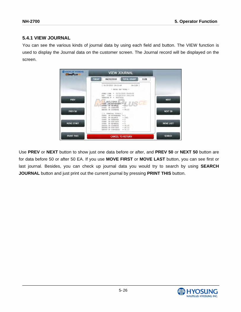
5.4.1 VIEW JOURNAL
You can see the various kinds of journal data by using each field and button. The VIEW function is
used to display the Journal data on the customer screen. The Journal record will be displayed on the
screen.
Use PREV or NEXT button to show just one data before or after, and PREV 50 or NEXT 50 button are
for data before 50 or after 50 EA. If you use MOVE FIRST or MOVE LAST button, you can see first or
last journal. Besides, you can check up journal data you would try to search by using SEARCH
JOURNAL button and just print out the current journal by pressing PRINT THIS button.
NH-2700 5. Operator Function
5- 27
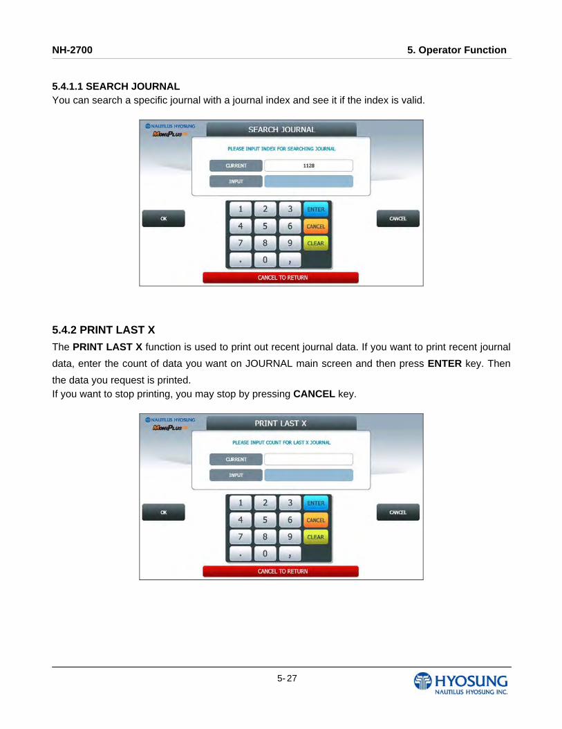
5.4.1.1 SEARCH JOURNAL You can search a specific journal with a journal index and see it if the index is valid.
5.4.2 PRINT LAST X
The PRINT LAST X function is used to print out recent journal data. If you want to print recent journal
data, enter the count of data you want on JOURNAL main screen and then press ENTER key. Then
the data you request is printed. If you want to stop printing, you may stop by pressing CANCEL key.
NH-2700 5. Operator Function
5- 28
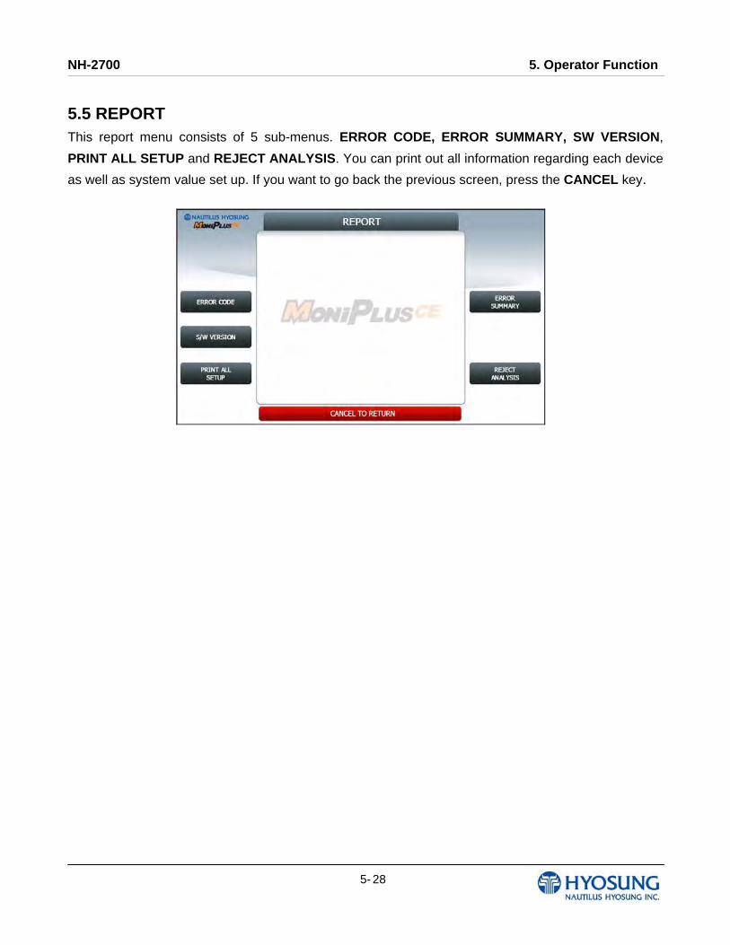
5.5 REPORT This report menu consists of 5 sub-menus. ERROR CODE, ERROR SUMMARY, SW VERSION,
PRINT ALL SETUP and REJECT ANALYSIS. You can print out all information regarding each device
as well as system value set up. If you want to go back the previous screen, press the CANCEL key.
NH-2700 5. Operator Function
5- 29
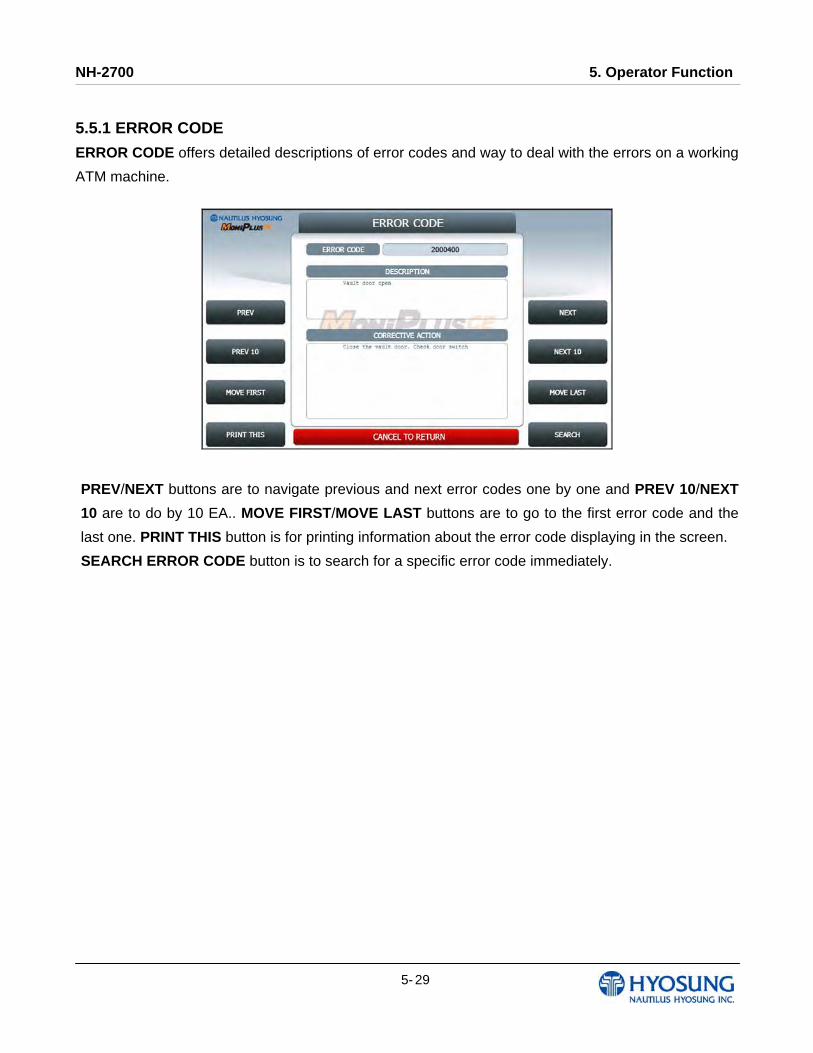
5.5.1 ERROR CODE
ERROR CODE offers detailed descriptions of error codes and way to deal with the errors on a working
ATM machine.
PREV/NEXT buttons are to navigate previous and next error codes one by one and PREV 10/NEXT
10 are to do by 10 EA.. MOVE FIRST/MOVE LAST buttons are to go to the first error code and the
last one. PRINT THIS button is for printing information about the error code displaying in the screen.
SEARCH ERROR CODE button is to search for a specific error code immediately.
NH-2700 5. Operator Function
5- 30
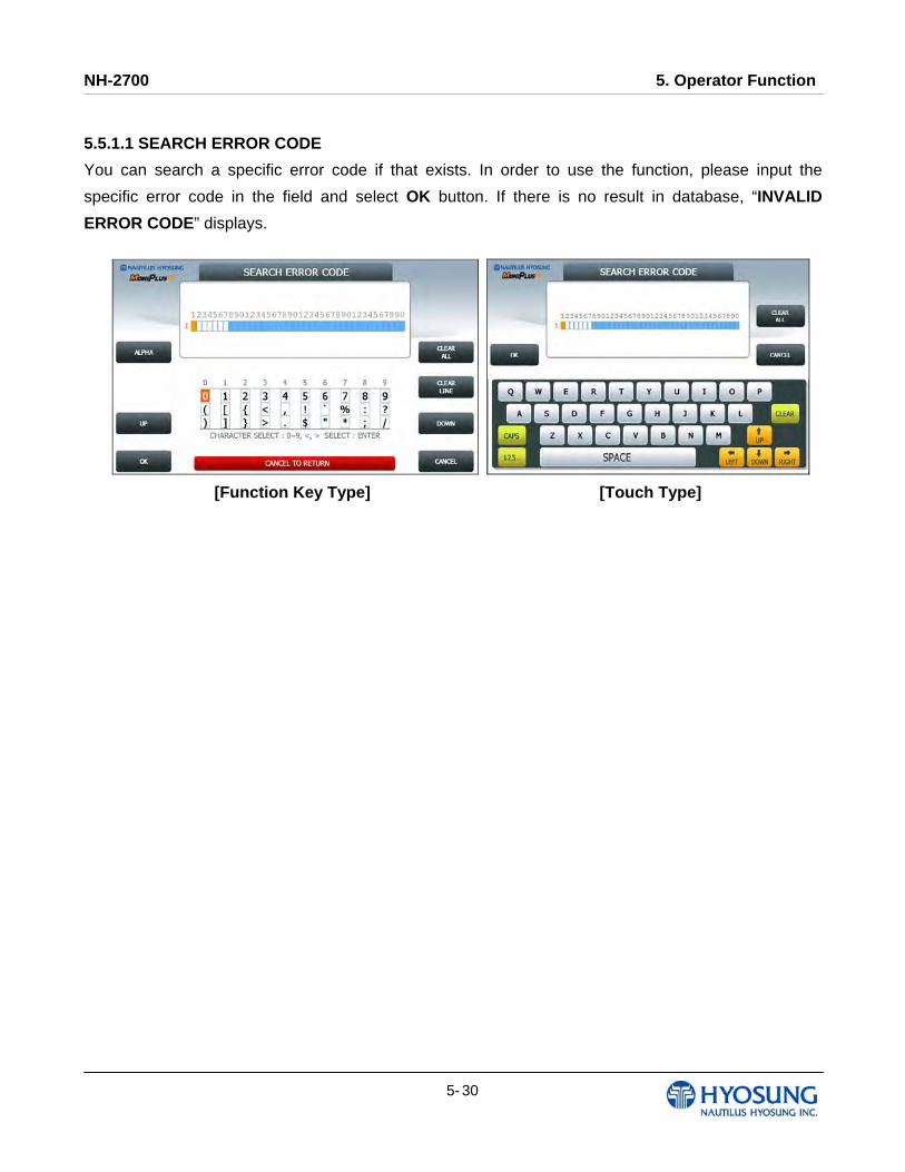
5.5.1.1 SEARCH ERROR CODE
You can search a specific error code if that exists. In order to use the function, please input the
specific error code in the field and select OK button. If there is no result in database, “INVALID
ERROR CODE” displays.
[Function Key Type] [Touch Type]
NH-2700 5. Operator Function
5- 31
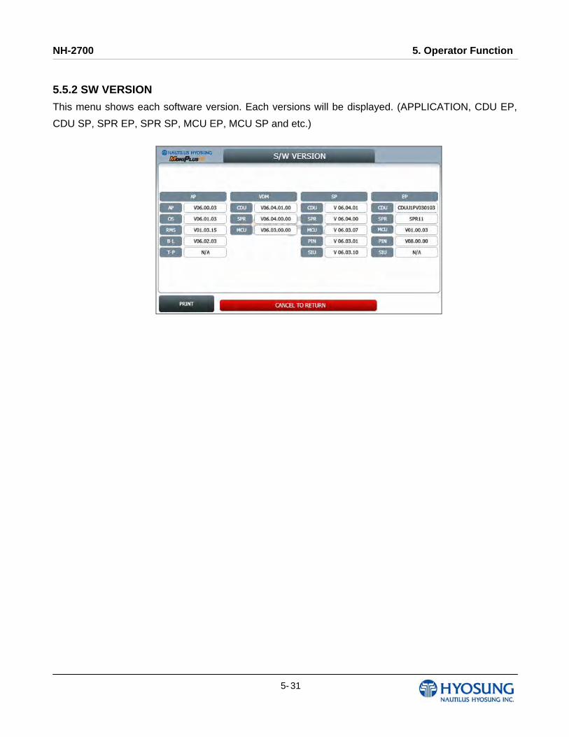
5.5.2 SW VERSION
This menu shows each software version. Each versions will be displayed. (APPLICATION, CDU EP,
CDU SP, SPR EP, SPR SP, MCU EP, MCU SP and etc.)
NH-2700 5. Operator Function
5- 32
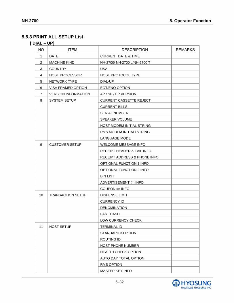
5.5.3 PRINT ALL SETUP List [ DIAL – UP]
NO ITEM DESCRIPTION REMARKS
1 DATE CURRENT DATE & TIME
2 MACHINE KIND NH-2700/ NH-2700 L/NH-2700 T
3 COUNTRY USA
4 HOST PROCESSOR HOST PROTOCOL TYPE
5 NETWORK TYPE DIAL-UP
6 VISA FRAMED OPTION EOT/ENQ OPTION
7 VERSION INFORMATION AP / SP / EP VERSION
CURRENT CASSETTE REJECT
CURRENT BILLS
SERIAL NUMBER
SPEAKER VOLUME
HOST MODEM INITIAL STRING
RMS MODEM INITIALI STRING
8 SYSTEM SETUP
LANGUAGE MODE
WELCOME MESSAGE INFO
RECEIPT HEADER & TAIL INFO
RECEIPT ADDRESS & PHONE INFO
OPTIONAL FUNCTION 1 INFO
OPTIONAL FUNCTION 2 INFO
BIN LIST
ADVERTISEMENT #n INFO
9 CUSTOMER SETUP
COUPON #n INFO
DISPENSE LIMIT
CURRENCY ID
DENOMINATION
FAST CASH
10 TRANSACTION SETUP
LOW CURRENCY CHECK
TERMINAL ID
STANDARD 3 OPTION
ROUTING ID
HOST PHONE NUMBER
HEALTH CHECK OPTION
AUTO DAY TOTAL OPTION
RMS OPTION
11 HOST SETUP
MASTER KEY INFO

NH-2700 5. Operator Function
5- 33
[ TCP / IP]
NO ITEM DESCRIPTION REMARKS
1 DATE CURRENT DATE & TIME
2 MACHINE KIND NH-2700/ NH-2700 L/NH-2700 T
3 COUNTRY USA
4 HOST PROCESSOR HOST PROTOCOL TYPE
5 NETWORK TYPE TCP/IP
6 TCP/IP TYPE TCP/IP TYPE
7 SSL MODE SSL OPTION
8 VERSION INFORMATION AP / SP / EP VERSION
CURRENT CASSETTE REJECT
CURRENT BILLS
SERIAL NUMBER
SPEAKER VOLUME
ATM IP OPTION
9 SYSTEM SETUP
LANGUAGE MODE
WELCOME MESSAGE INFO
RECEIPT HEADER & TAIL INFO
RECEIPT ADDRESS & PHONE INFO
OPTIONAL FUNCTION 1 INFO
OPTIONAL FUNCTION 2 INFO
BIN LIST
ADVERTISEMENT #n INFO
10 CUSTOMER SETUP
COUPON #n INFO
DISPENSE LIMIT
CURRENCY ID
DENOMINATION
FAST CASH
11 TRANSACTION SETUP
LOW CURRENCY CHECK
TERMINAL ID
STANDARD 3 OPTION
ROUTING ID
HOST ADDRESS INFO
HEALTH CHECK OPTION
AUTO DAY TOTAL OPTION
RMS OPTION
12 HOST SETUP
MASTER KEY INFO

NH-2700 5. Operator Function
5- 34
5.5.4 ERROR SUMMARY
ERROR SUMMARY menu offers a statistics of error codes on an ATM machine. It lists the errors by
the number of times they occurred. You can print these errors.
PREV/NEXT buttons are to navigate previous and next pages and PRINT button prints all of error
code history.
CLEAR button erases the history stacked in an ATM machine and set START DATE to the present
date as well. (START DATE displays “01/01/2000 00:00:00” in ATM machines which have never
done the CLEAR function.)
NH-2700 5. Operator Function
5- 35
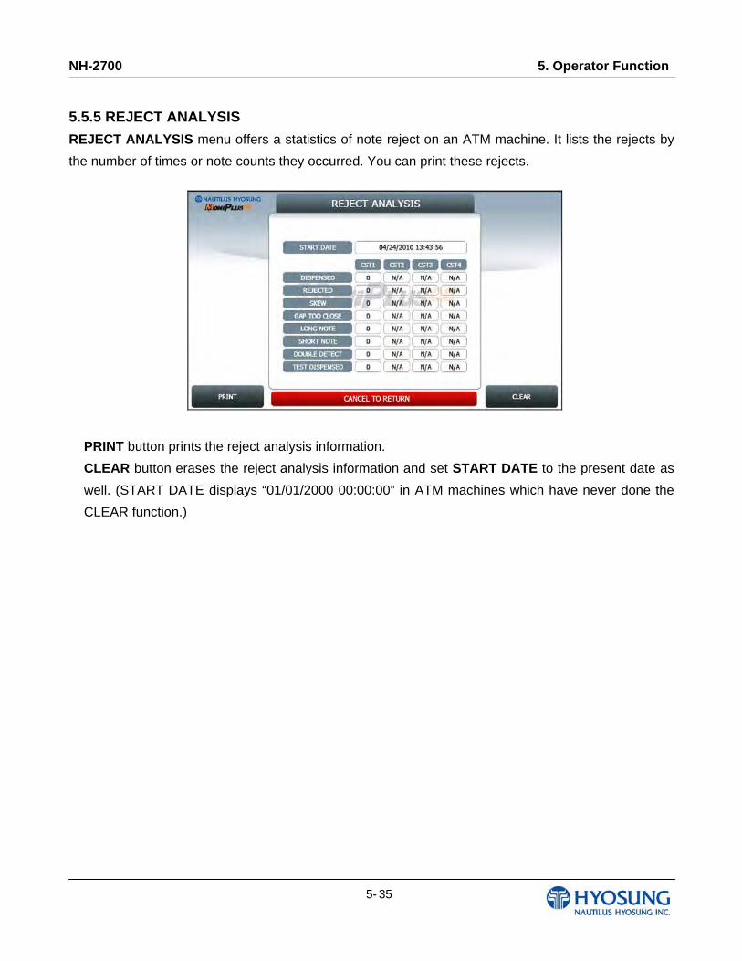
5.5.5 REJECT ANALYSIS
REJECT ANALYSIS menu offers a statistics of note reject on an ATM machine. It lists the rejects by
the number of times or note counts they occurred. You can print these rejects.
PRINT button prints the reject analysis information.
CLEAR button erases the reject analysis information and set START DATE to the present date as
well. (START DATE displays “01/01/2000 00:00:00” in ATM machines which have never done the
CLEAR function.)

NH-2700 5. Operator Function
5- 36
5.6 DIAGNOSTICS This report menu consists of 7 sub-menus. INITIALIZE, RECEIPT PRINTER, CASH DISPENSER,
MODEM (or TCP/IP), CARD SCAN, AUXILIARY UNIT and AGING. Please press each button on this
menu to go to next screen or to operate the related function. To go back to the previous screen, press
the CANCEL key in pinpad.
[Function Key Type] [Touch Type]

NH-2700 5. Operator Function
5- 37
Changing the TEST COUNT
The TEST COUNT means the number of test.
If you want to change the test count, press BLANK key or SET button then input the test count and press ENTER key. To delete the test count while inputting, press CLEAR key. To cancel the test while testing, press CANCEL key.
NOTE: TEST COUNT affects when testing RECEIPT PRINTER, CASH DISPENSER, and MODEM.
CASE:
1) If you input test count ‘0’, the test count will be “UNLIMIT”
2) If you input test count 10, the test will perform 10 times.
3) If you cancel a test and then perform same test, the test count will be continue.
e.g. If you cancel a test when the tested count is 3, and then perform same test, the tested
count starts at 3.
4) If you cancel a test and then perform another test, the test count will be initialized.
e.g. If you cancel a test when the tested count is 3, and then perform another test, the tested
count starts at 0.
BLANK Key
NH-2700 5. Operator Function
5- 38
5.6.1 INITIALIZE
The INITIALIZE has the function of resetting each unit of the NH-2700. If an error occurs while
executing, the system will stop and display an error code. Confirm the detailed error description in the
ERROR CODE of REPORT MENU.
Accessing the INITIALIZE 1) Select DIAGNOSTICS in the OPERATOR FUNCTION
2) Select the INITIALIZE in the DIAGNOSTICS menu. All units will be initialized.
3) When the ATM is in the normal state, the SUCCESS message will be displayed.
5.6.2 RECEIPT PRINTER
The RECEIPT PRINTER has the function of printing a sample receipt and cutting out one receipt. If an
error occurs while executing, the system will stop and display an error code. Confirm the detailed error
description in the ERROR CODE of REPORT MENU.
Accessing the RECEIPT PRINTER 1) Select DIAGNOSTICS in the OPERATOR FUNCTION.
2) Select the RECEIPT PRINTER in the DIAGNOSTICS menu. Test String will be printed from the
receipt printer.
3) When the ATM is in the normal state, the SUCESS message will be displayed.
5.6.3 CASH DISPENSER
The CASH DISPENSER has the function of testing the dispense mechanisms. This function will
dispense one note from the cassette and dump into the reject bin. If an error occurs, the system will
stop and display an error code. Confirm the detailed error description in the ERROR CODE of
REPORT MENU Accessing the CASH DISPENSER 1) Select DIAGNOSTICS in the OPERATOR FUNCTION.
2) Select the CASH DISPENSER in the DIAGNOSTICS menu. The CASH DISPENSER test will be
performed.
3) When the ATM is normal state, the SUCCESS message will be displayed.
NH-2700 5. Operator Function
5- 39
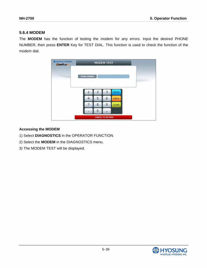
5.6.4 MODEM
The MODEM has the function of testing the modem for any errors. Input the desired PHONE
NUMBER, then press ENTER Key for TEST DIAL. This function is used to check the function of the
modem dial.
Accessing the MODEM
1) Select DIAGNOSTICS in the OPERATOR FUNCTION.
2) Select the MODEM in the DIAGNOSTICS menu.
3) The MODEM TEST will be displayed.
NH-2700 5. Operator Function
5- 40
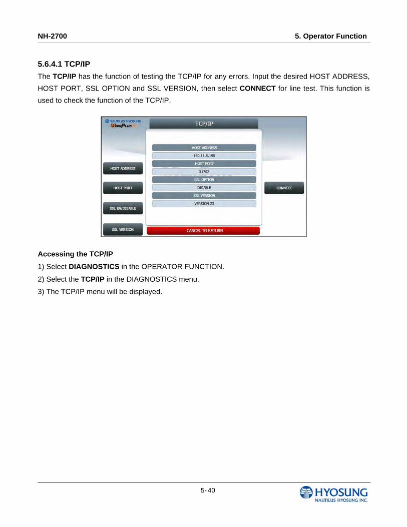
5.6.4.1 TCP/IP
The TCP/IP has the function of testing the TCP/IP for any errors. Input the desired HOST ADDRESS,
HOST PORT, SSL OPTION and SSL VERSION, then select CONNECT for line test. This function is
used to check the function of the TCP/IP.
Accessing the TCP/IP
1) Select DIAGNOSTICS in the OPERATOR FUNCTION.
2) Select the TCP/IP in the DIAGNOSTICS menu.
3) The TCP/IP menu will be displayed.
NH-2700 5. Operator Function
5- 41
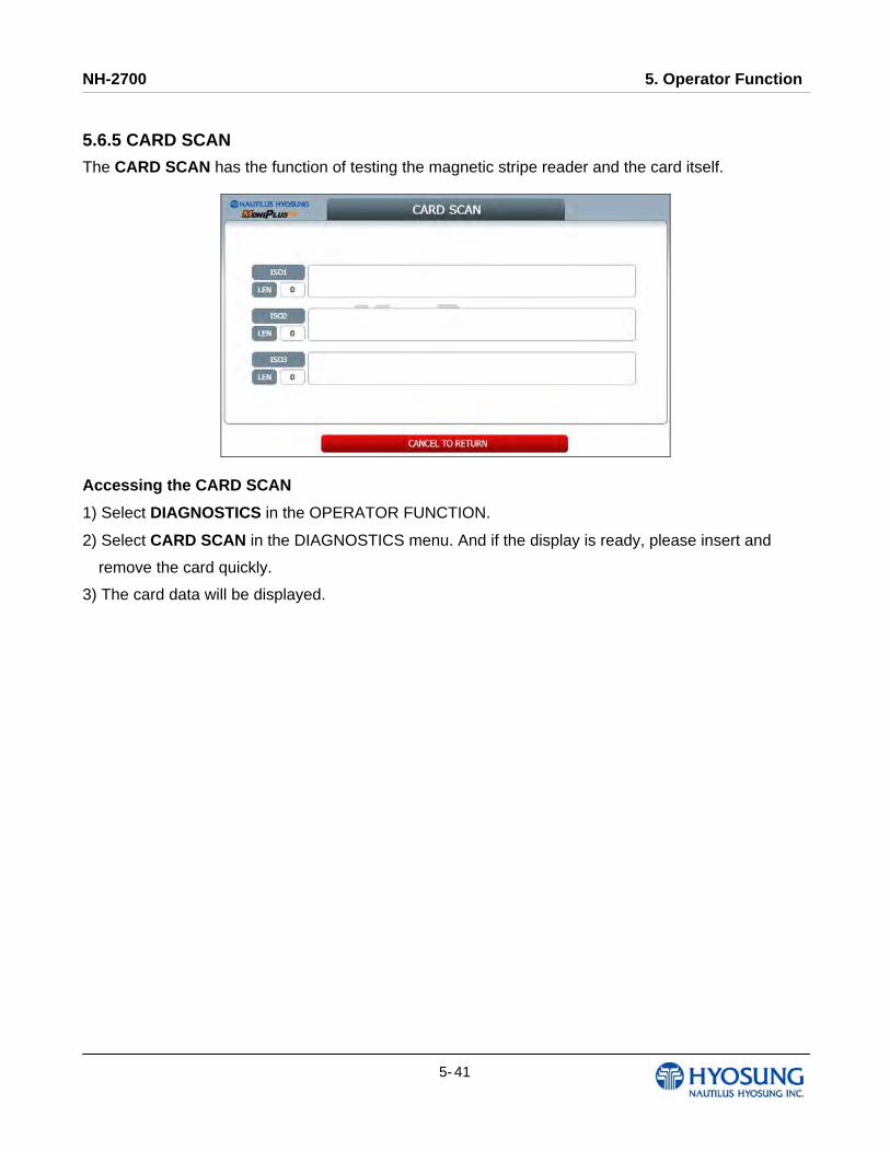
5.6.5 CARD SCAN
The CARD SCAN has the function of testing the magnetic stripe reader and the card itself.
Accessing the CARD SCAN
1) Select DIAGNOSTICS in the OPERATOR FUNCTION.
2) Select CARD SCAN in the DIAGNOSTICS menu. And if the display is ready, please insert and
remove the card quickly.
3) The card data will be displayed.
NH-2700 5. Operator Function
5- 42
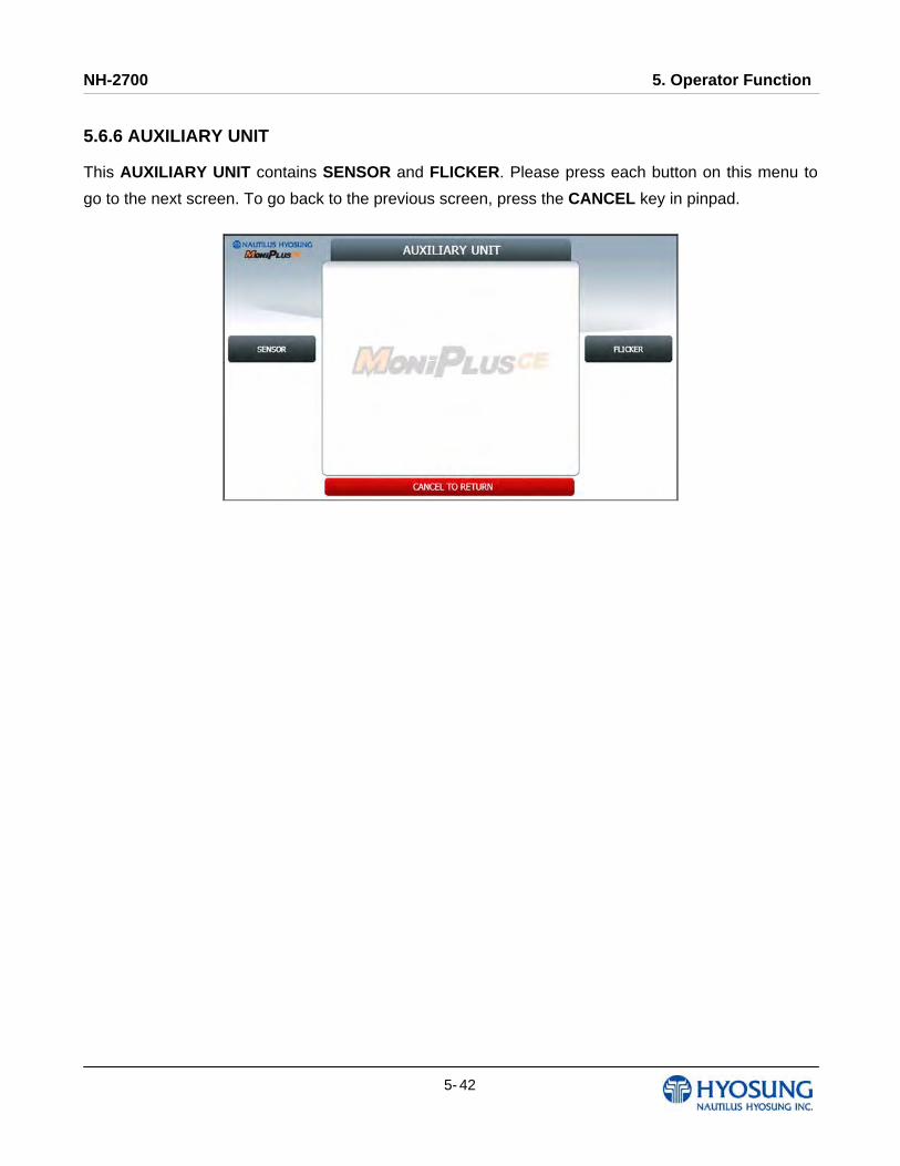
5.6.6 AUXILIARY UNIT
This AUXILIARY UNIT contains SENSOR and FLICKER. Please press each button on this menu to
go to the next screen. To go back to the previous screen, press the CANCEL key in pinpad.
NH-2700 5. Operator Function
5- 43
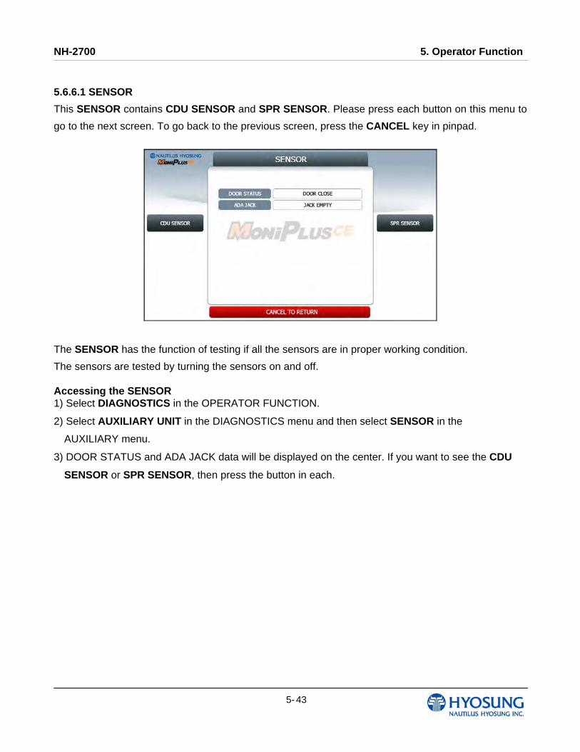
5.6.6.1 SENSOR
This SENSOR contains CDU SENSOR and SPR SENSOR. Please press each button on this menu to
go to the next screen. To go back to the previous screen, press the CANCEL key in pinpad.
The SENSOR has the function of testing if all the sensors are in proper working condition.
The sensors are tested by turning the sensors on and off. Accessing the SENSOR 1) Select DIAGNOSTICS in the OPERATOR FUNCTION.
2) Select AUXILIARY UNIT in the DIAGNOSTICS menu and then select SENSOR in the
AUXILIARY menu.
3) DOOR STATUS and ADA JACK data will be displayed on the center. If you want to see the CDU
SENSOR or SPR SENSOR, then press the button in each.
NH-2700 5. Operator Function
5- 44
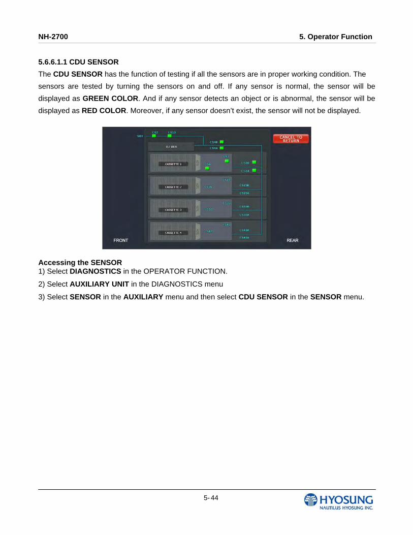
5.6.6.1.1 CDU SENSOR
The CDU SENSOR has the function of testing if all the sensors are in proper working condition. The
sensors are tested by turning the sensors on and off. If any sensor is normal, the sensor will be
displayed as GREEN COLOR. And if any sensor detects an object or is abnormal, the sensor will be
displayed as RED COLOR. Moreover, if any sensor doesn’t exist, the sensor will not be displayed.
Accessing the SENSOR 1) Select DIAGNOSTICS in the OPERATOR FUNCTION.
2) Select AUXILIARY UNIT in the DIAGNOSTICS menu
3) Select SENSOR in the AUXILIARY menu and then select CDU SENSOR in the SENSOR menu.
NH-2700 5. Operator Function
5- 45
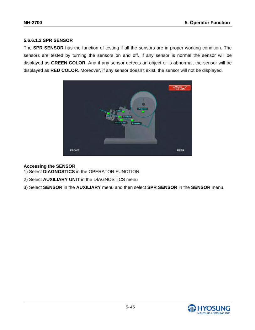
5.6.6.1.2 SPR SENSOR
The SPR SENSOR has the function of testing if all the sensors are in proper working condition. The
sensors are tested by turning the sensors on and off. If any sensor is normal the sensor will be
displayed as GREEN COLOR. And if any sensor detects an object or is abnormal, the sensor will be
displayed as RED COLOR. Moreover, if any sensor doesn’t exist, the sensor will not be displayed.
Accessing the SENSOR 1) Select DIAGNOSTICS in the OPERATOR FUNCTION.
2) Select AUXILIARY UNIT in the DIAGNOSTICS menu
3) Select SENSOR in the AUXILIARY menu and then select SPR SENSOR in the SENSOR menu.
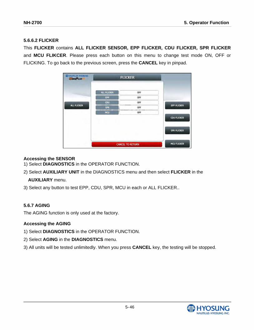
NH-2700 5. Operator Function
5- 46
5.6.6.2 FLICKER
This FLICKER contains ALL FLICKER SENSOR, EPP FLICKER, CDU FLICKER, SPR FLICKER
and MCU FLIKCER. Please press each button on this menu to change test mode ON, OFF or
FLICKING. To go back to the previous screen, press the CANCEL key in pinpad.
Accessing the SENSOR 1) Select DIAGNOSTICS in the OPERATOR FUNCTION.
2) Select AUXILIARY UNIT in the DIAGNOSTICS menu and then select FLICKER in the
AUXILIARY menu.
3) Select any button to test EPP, CDU, SPR, MCU in each or ALL FLICKER..
5.6.7 AGING
The AGING function is only used at the factory. Accessing the AGING
1) Select DIAGNOSTICS in the OPERATOR FUNCTION.
2) Select AGING in the DIAGNOSTICS menu.
3) All units will be tested unlimitedly. When you press CANCEL key, the testing will be stopped.
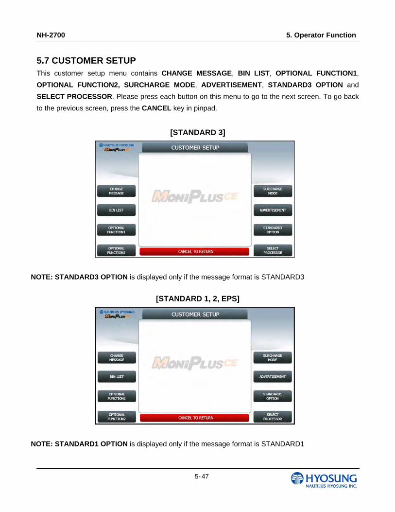
NH-2700 5. Operator Function
5- 47
5.7 CUSTOMER SETUP This customer setup menu contains CHANGE MESSAGE, BIN LIST, OPTIONAL FUNCTION1,
OPTIONAL FUNCTION2, SURCHARGE MODE, ADVERTISEMENT, STANDARD3 OPTION and
SELECT PROCESSOR. Please press each button on this menu to go to the next screen. To go back
to the previous screen, press the CANCEL key in pinpad.
[STANDARD 3]
NOTE: STANDARD3 OPTION is displayed only if the message format is STANDARD3
[STANDARD 1, 2, EPS]
NOTE: STANDARD1 OPTION is displayed only if the message format is STANDARD1
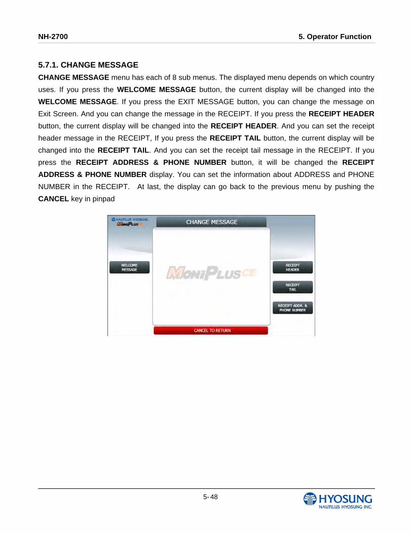
NH-2700 5. Operator Function
5- 48
5.7.1. CHANGE MESSAGE
CHANGE MESSAGE menu has each of 8 sub menus. The displayed menu depends on which country
uses. If you press the WELCOME MESSAGE button, the current display will be changed into the
WELCOME MESSAGE. If you press the EXIT MESSAGE button, you can change the message on
Exit Screen. And you can change the message in the RECEIPT. If you press the RECEIPT HEADER
button, the current display will be changed into the RECEIPT HEADER. And you can set the receipt
header message in the RECEIPT, If you press the RECEIPT TAIL button, the current display will be
changed into the RECEIPT TAIL. And you can set the receipt tail message in the RECEIPT. If you
press the RECEIPT ADDRESS & PHONE NUMBER button, it will be changed the RECEIPT
ADDRESS & PHONE NUMBER display. You can set the information about ADDRESS and PHONE
NUMBER in the RECEIPT. At last, the display can go back to the previous menu by pushing the
CANCEL key in pinpad
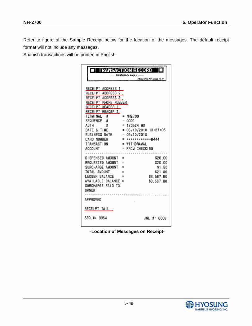
NH-2700 5. Operator Function
5- 49
Refer to figure of the Sample Receipt below for the location of the messages. The default receipt
format will not include any messages.
Spanish transactions will be printed in English.
-Location of Messages on Receipt-
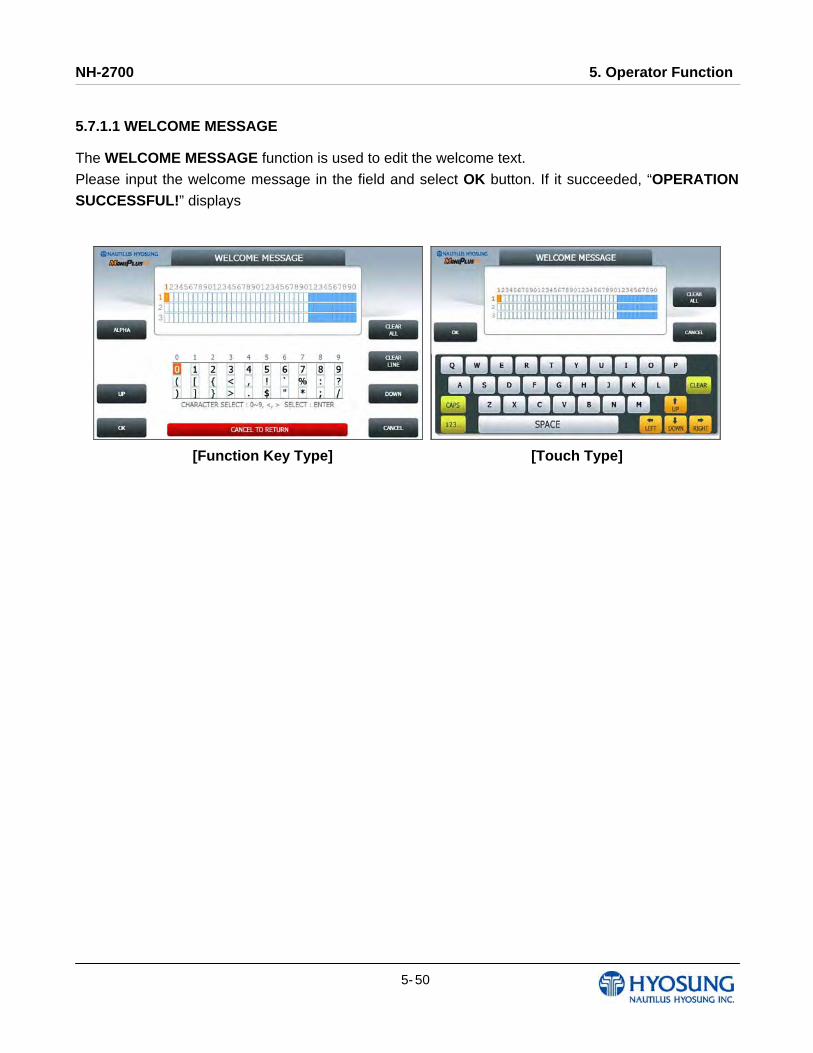
NH-2700 5. Operator Function
5- 50
5.7.1.1 WELCOME MESSAGE
The WELCOME MESSAGE function is used to edit the welcome text.
Please input the welcome message in the field and select OK button. If it succeeded, “OPERATION SUCCESSFUL!” displays
[Function Key Type] [Touch Type]
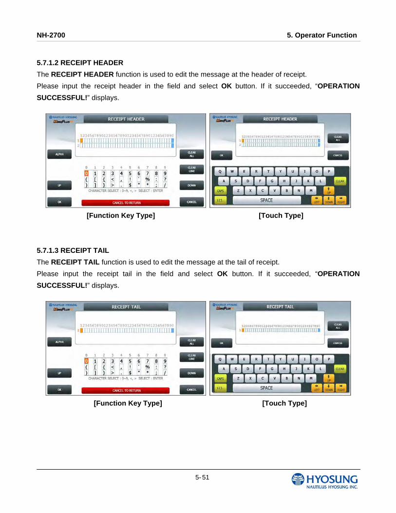
NH-2700 5. Operator Function
5- 51
5.7.1.2 RECEIPT HEADER
The RECEIPT HEADER function is used to edit the message at the header of receipt.
Please input the receipt header in the field and select OK button. If it succeeded, “OPERATION
SUCCESSFUL!” displays.
[Function Key Type] [Touch Type]
5.7.1.3 RECEIPT TAIL
The RECEIPT TAIL function is used to edit the message at the tail of receipt.
Please input the receipt tail in the field and select OK button. If it succeeded, “OPERATION
SUCCESSFUL!” displays.
[Function Key Type] [Touch Type]
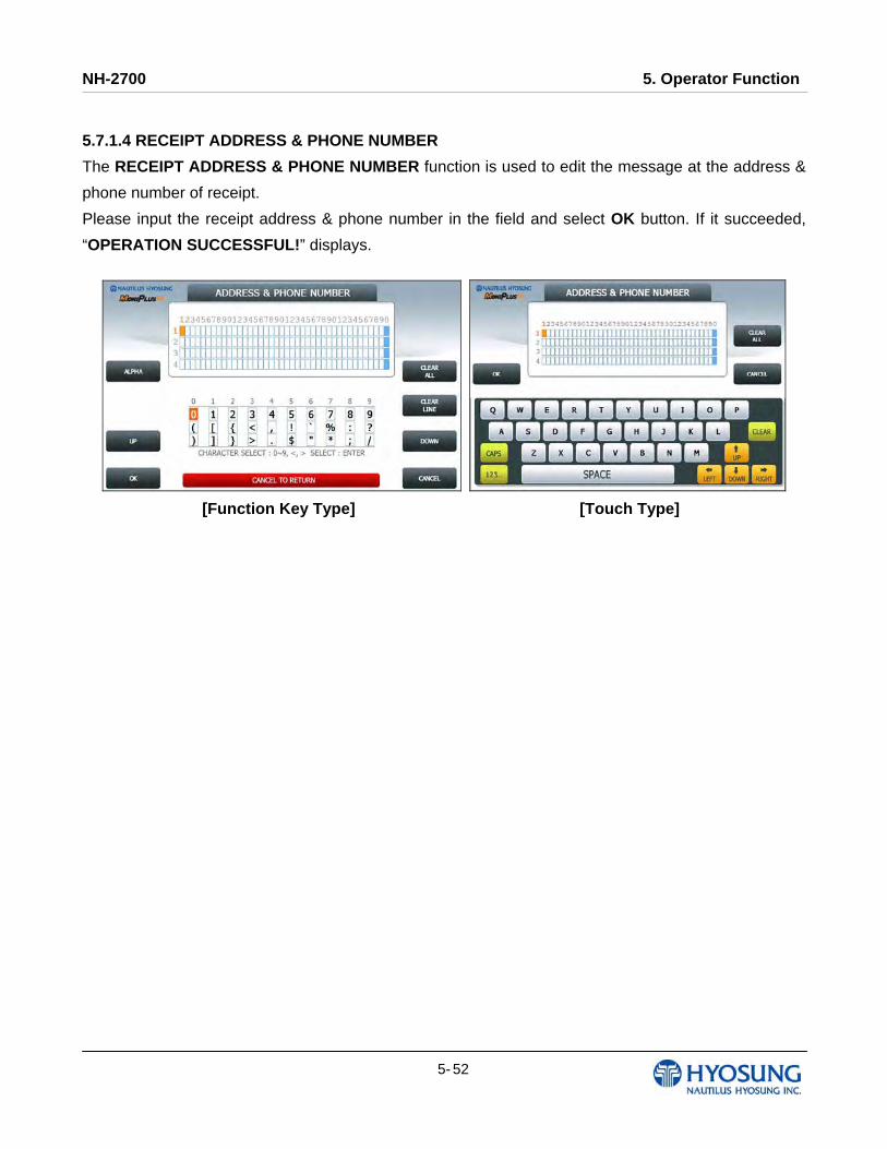
NH-2700 5. Operator Function
5- 52
5.7.1.4 RECEIPT ADDRESS & PHONE NUMBER
The RECEIPT ADDRESS & PHONE NUMBER function is used to edit the message at the address &
phone number of receipt.
Please input the receipt address & phone number in the field and select OK button. If it succeeded,
“OPERATION SUCCESSFUL!” displays.
[Function Key Type] [Touch Type]

NH-2700 5. Operator Function
5- 53
5.7.2. BIN(Bank Identification Number) LIST
The BIN LIST is used to register the bank identification number. When the cardholders make
transaction with the given BIN code, ATM doesn’t request any additional fee. However, it is necessary
to confirm the connected host because host will decide whether it uses or not
You can input and edit it by using such as ADD, DELETE, EDIT, DELETE ALL button.
Please press EXTENDED BIN LIST button on this menu to see the Extended Bin List. To go back to
the previous screen, press the CANCEL key in pinpad.
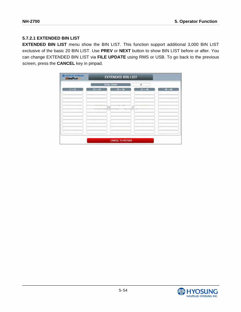
NH-2700 5. Operator Function
5- 54
5.7.2.1 EXTENDED BIN LIST EXTENDED BIN LIST menu show the BIN LIST. This function support additional 3,000 BIN LIST
exclusive of the basic 20 BIN LIST. Use PREV or NEXT button to show BIN LIST before or after. You
can change EXTENDED BIN LIST via FILE UPDATE using RMS or USB. To go back to the previous
screen, press the CANCEL key in pinpad.
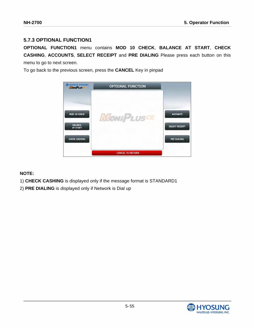
NH-2700 5. Operator Function
5- 55
5.7.3 OPTIONAL FUNCTION1
OPTIONAL FUNCTION1 menu contains MOD 10 CHECK, BALANCE AT START, CHECK
CASHING, ACCOUNTS, SELECT RECEIPT and PRE DIALING Please press each button on this
menu to go to next screen.
To go back to the previous screen, press the CANCEL Key in pinpad
NOTE:
1) CHECK CASHING is displayed only if the message format is STANDARD1
2) PRE DIALING is displayed only if Network is Dial up

NH-2700 5. Operator Function
5- 56
5.7.3.1 MOD 10 CHECK
MOD 10 CHECK is to check the card data’s validation.
Please press EN/DISABLE button to set up MOD 10 CHECK.
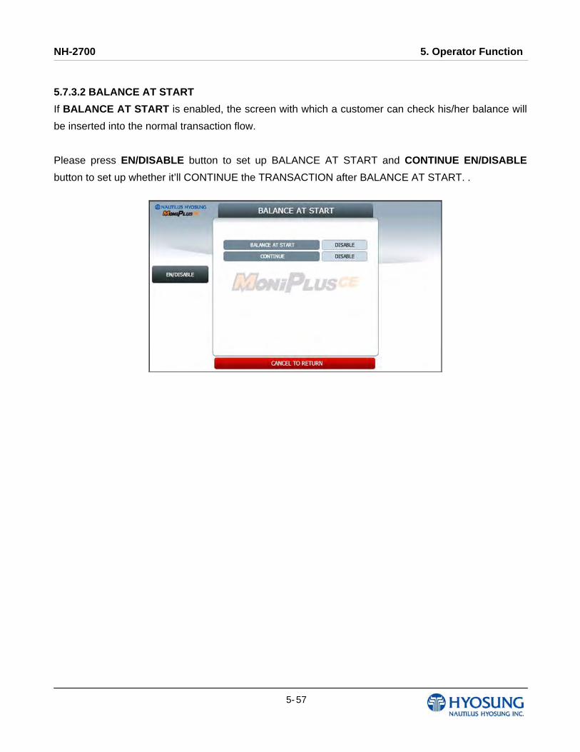
NH-2700 5. Operator Function
5- 57
5.7.3.2 BALANCE AT START
If BALANCE AT START is enabled, the screen with which a customer can check his/her balance will
be inserted into the normal transaction flow.
Please press EN/DISABLE button to set up BALANCE AT START and CONTINUE EN/DISABLE
button to set up whether it’ll CONTINUE the TRANSACTION after BALANCE AT START. .
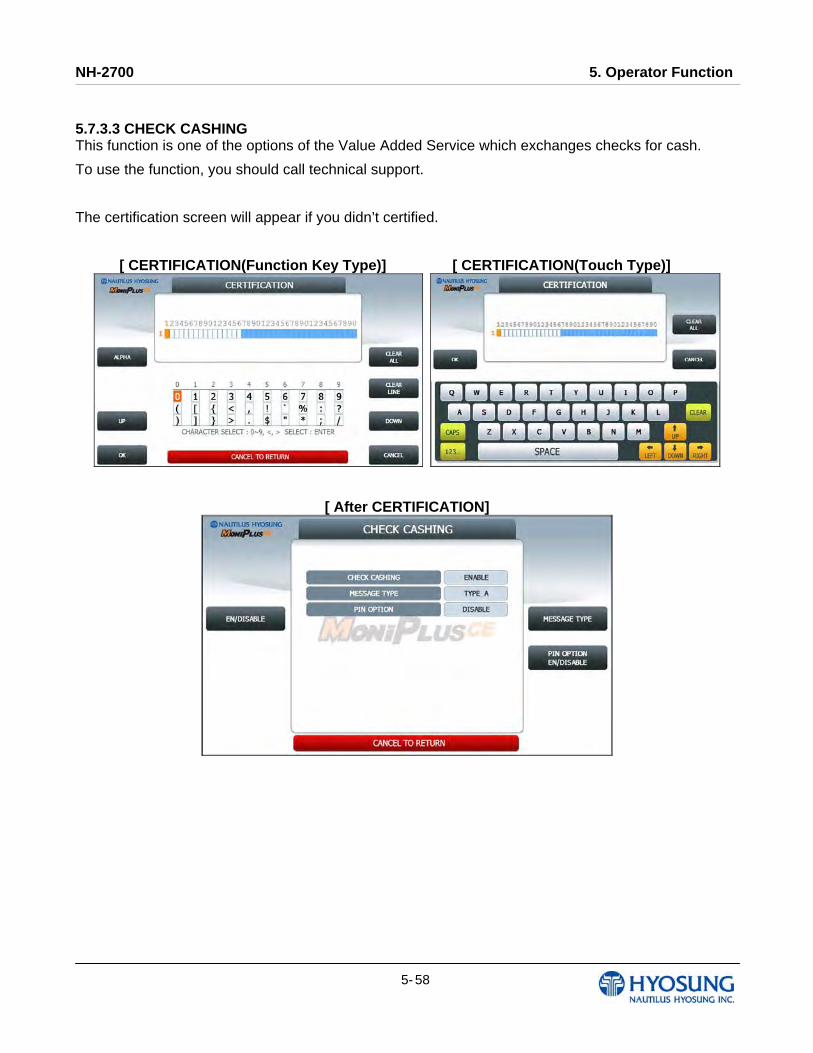
NH-2700 5. Operator Function
5- 58
5.7.3.3 CHECK CASHING This function is one of the options of the Value Added Service which exchanges checks for cash.
To use the function, you should call technical support.
The certification screen will appear if you didn’t certified.
[ CERTIFICATION(Function Key Type)] [ CERTIFICATION(Touch Type)]
[ After CERTIFICATION]
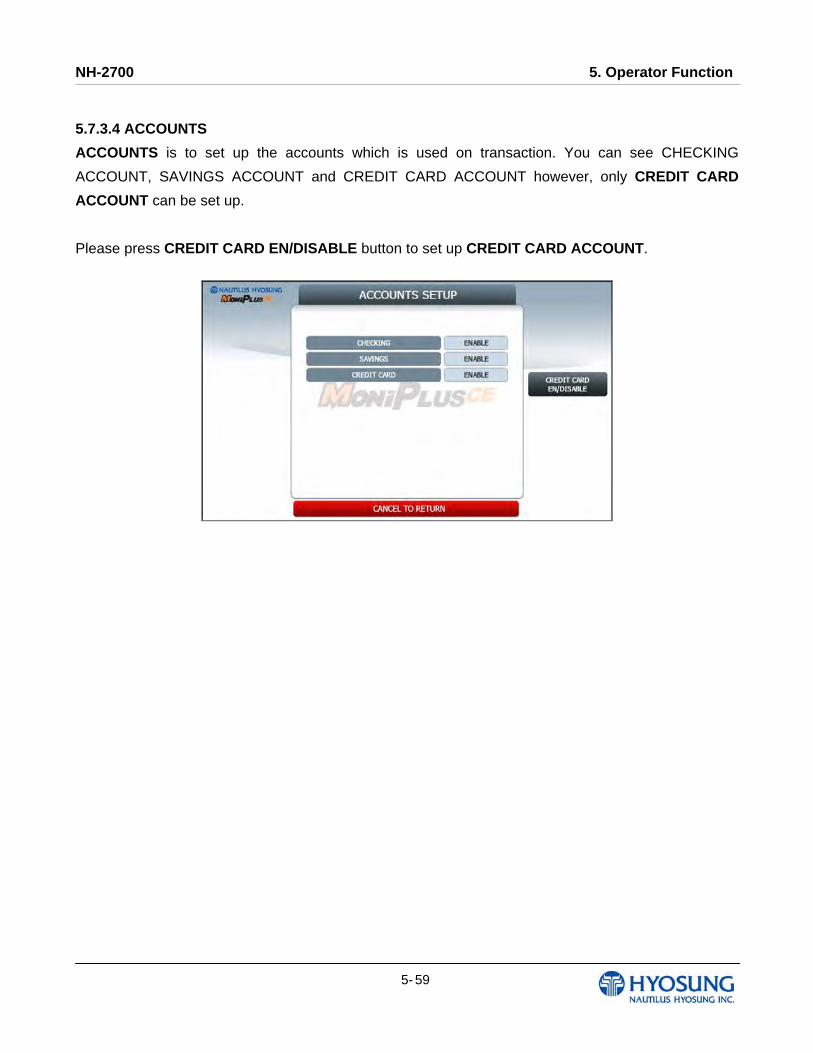
NH-2700 5. Operator Function
5- 59
5.7.3.4 ACCOUNTS
ACCOUNTS is to set up the accounts which is used on transaction. You can see CHECKING
ACCOUNT, SAVINGS ACCOUNT and CREDIT CARD ACCOUNT however, only CREDIT CARD
ACCOUNT can be set up.
Please press CREDIT CARD EN/DISABLE button to set up CREDIT CARD ACCOUNT.
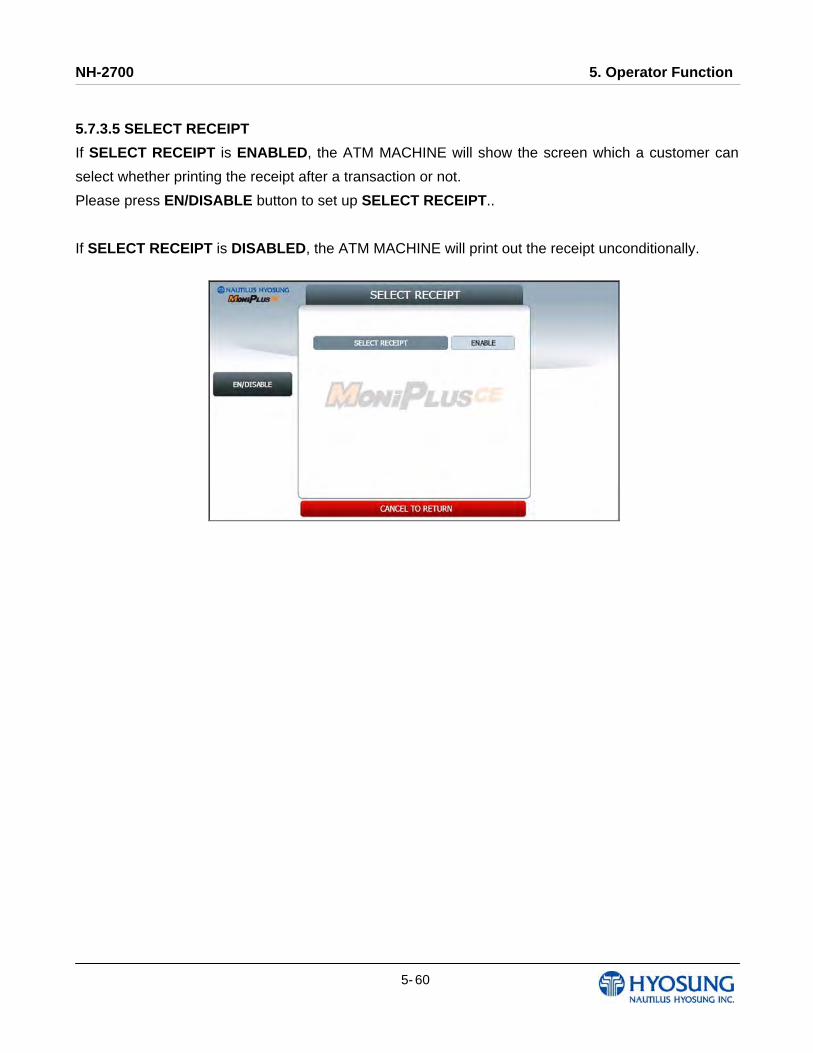
NH-2700 5. Operator Function
5- 60
5.7.3.5 SELECT RECEIPT
If SELECT RECEIPT is ENABLED, the ATM MACHINE will show the screen which a customer can
select whether printing the receipt after a transaction or not.
Please press EN/DISABLE button to set up SELECT RECEIPT..
If SELECT RECEIPT is DISABLED, the ATM MACHINE will print out the receipt unconditionally.
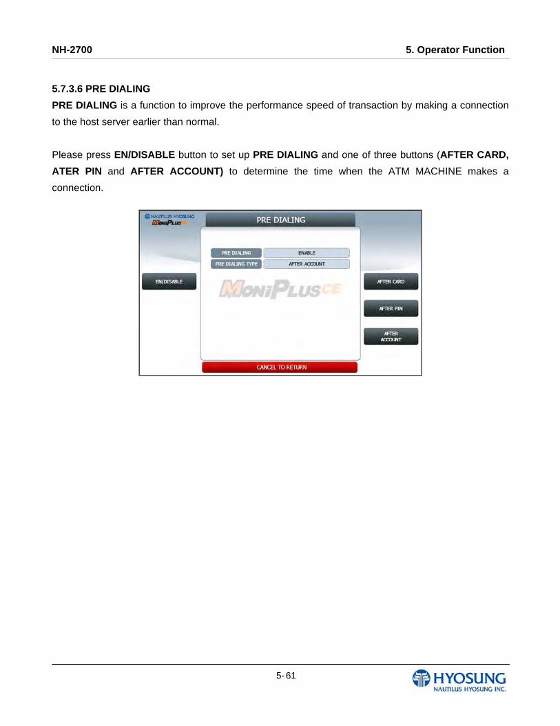
NH-2700 5. Operator Function
5- 61
5.7.3.6 PRE DIALING
PRE DIALING is a function to improve the performance speed of transaction by making a connection
to the host server earlier than normal.
Please press EN/DISABLE button to set up PRE DIALING and one of three buttons (AFTER CARD,
ATER PIN and AFTER ACCOUNT) to determine the time when the ATM MACHINE makes a
connection.

NH-2700 5. Operator Function
5- 62
5.7.4 OPTIONAL FUNCTION2
OPTIONAL FUNCTION2 menu contains DEVICE OPTION and SCREEN SERVICES.
To go back to the previous screen, press the CANCEL Key in pinpad
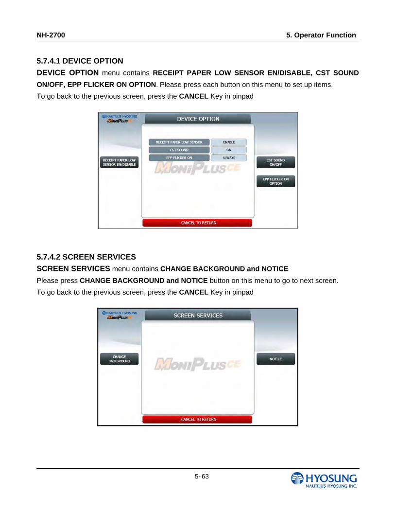
NH-2700 5. Operator Function
5- 63
5.7.4.1 DEVICE OPTION
DEVICE OPTION menu contains RECEIPT PAPER LOW SENSOR EN/DISABLE, CST SOUND
ON/OFF, EPP FLICKER ON OPTION. Please press each button on this menu to set up items.
To go back to the previous screen, press the CANCEL Key in pinpad
5.7.4.2 SCREEN SERVICES
SCREEN SERVICES menu contains CHANGE BACKGROUND and NOTICE
Please press CHANGE BACKGROUND and NOTICE button on this menu to go to next screen.
To go back to the previous screen, press the CANCEL Key in pinpad
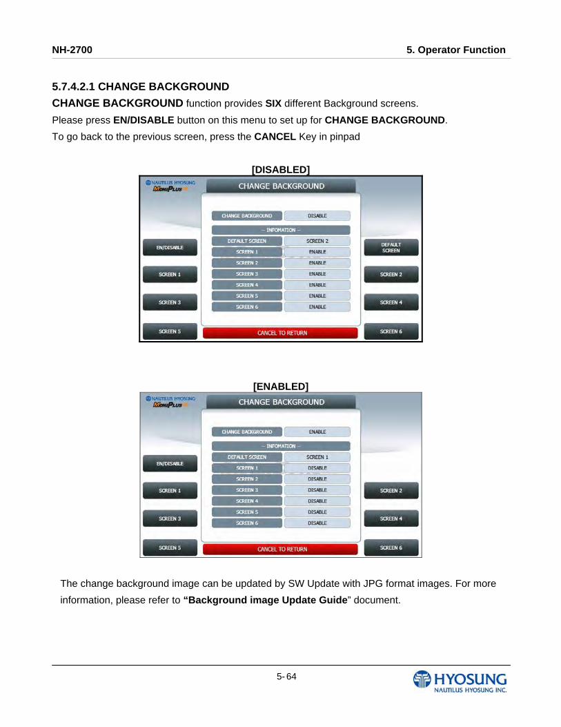
NH-2700 5. Operator Function
5- 64
5.7.4.2.1 CHANGE BACKGROUND
CHANGE BACKGROUND function provides SIX different Background screens.
Please press EN/DISABLE button on this menu to set up for CHANGE BACKGROUND.
To go back to the previous screen, press the CANCEL Key in pinpad
[DISABLED]
[ENABLED]
The change background image can be updated by SW Update with JPG format images. For more
information, please refer to “Background image Update Guide” document.
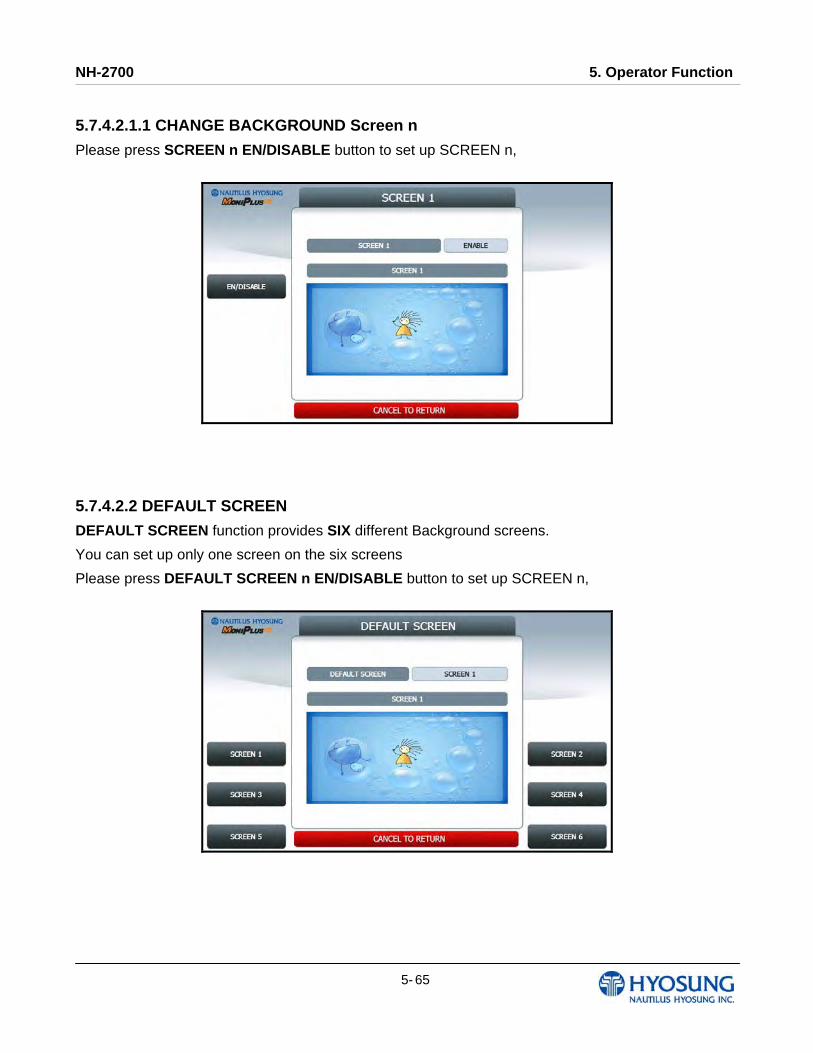
NH-2700 5. Operator Function
5- 65
5.7.4.2.1.1 CHANGE BACKGROUND Screen n
Please press SCREEN n EN/DISABLE button to set up SCREEN n,
5.7.4.2.2 DEFAULT SCREEN
DEFAULT SCREEN function provides SIX different Background screens.
You can set up only one screen on the six screens
Please press DEFAULT SCREEN n EN/DISABLE button to set up SCREEN n,
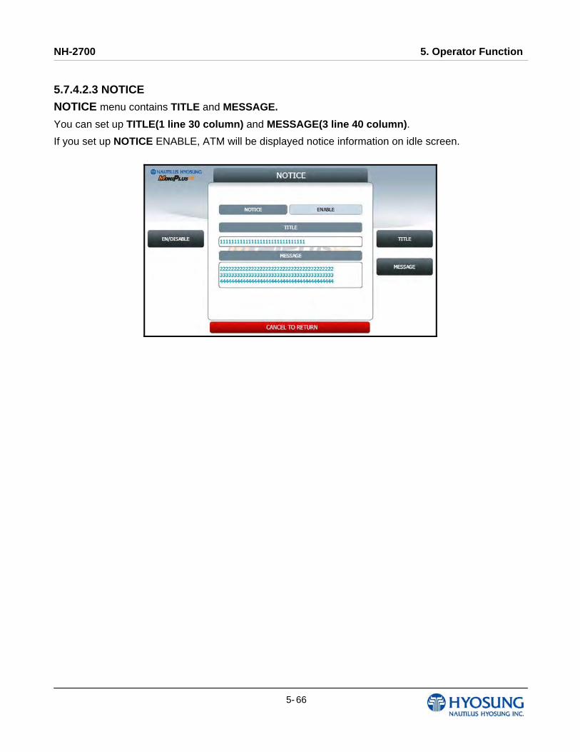
NH-2700 5. Operator Function
5- 66
5.7.4.2.3 NOTICE
NOTICE menu contains TITLE and MESSAGE.
You can set up TITLE(1 line 30 column) and MESSAGE(3 line 40 column).
If you set up NOTICE ENABLE, ATM will be displayed notice information on idle screen.
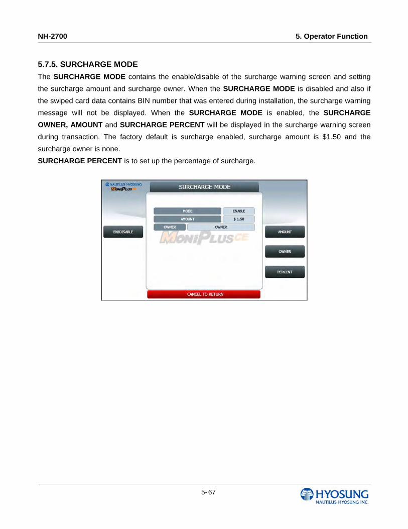
NH-2700 5. Operator Function
5- 67
5.7.5. SURCHARGE MODE
The SURCHARGE MODE contains the enable/disable of the surcharge warning screen and setting
the surcharge amount and surcharge owner. When the SURCHARGE MODE is disabled and also if
the swiped card data contains BIN number that was entered during installation, the surcharge warning
message will not be displayed. When the SURCHARGE MODE is enabled, the SURCHARGE
OWNER, AMOUNT and SURCHARGE PERCENT will be displayed in the surcharge warning screen
during transaction. The factory default is surcharge enabled, surcharge amount is $1.50 and the
surcharge owner is none.
SURCHARGE PERCENT is to set up the percentage of surcharge.
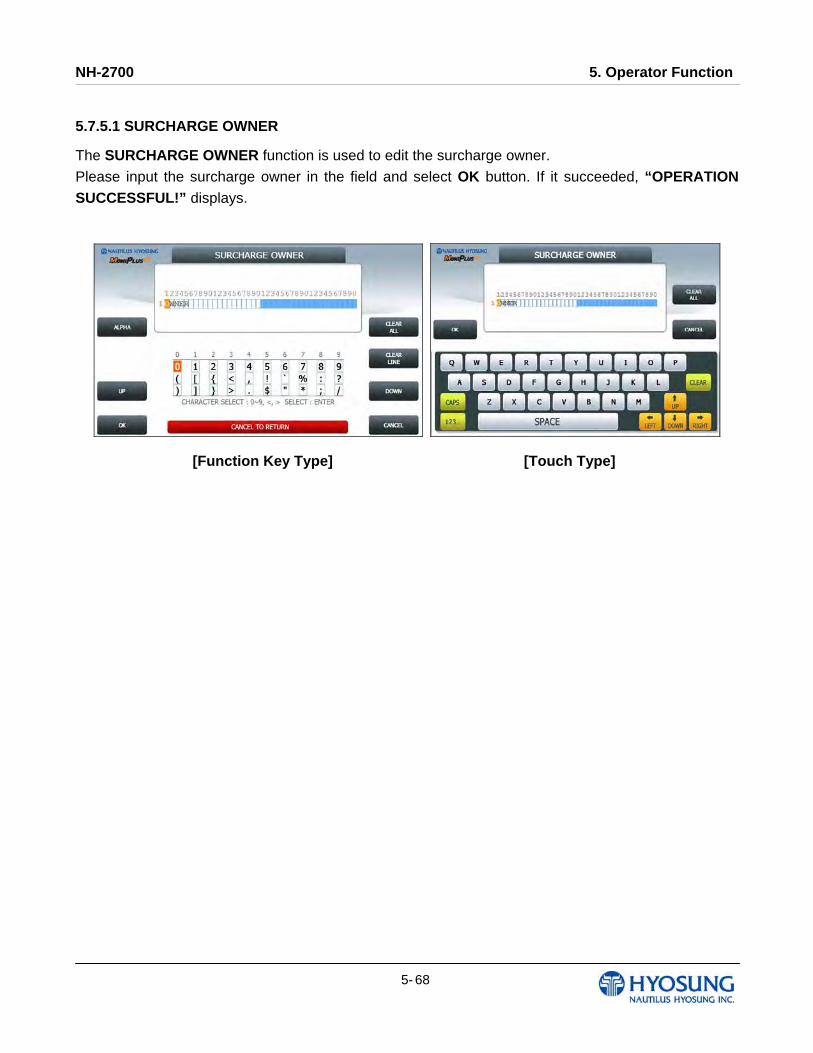
NH-2700 5. Operator Function
5- 68
5.7.5.1 SURCHARGE OWNER
The SURCHARGE OWNER function is used to edit the surcharge owner.
Please input the surcharge owner in the field and select OK button. If it succeeded, “OPERATION
SUCCESSFUL!” displays.
[Function Key Type] [Touch Type]
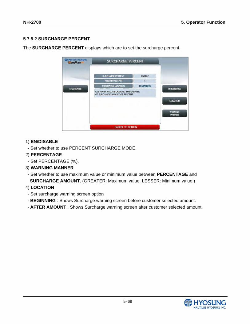
NH-2700 5. Operator Function
5- 69
5.7.5.2 SURCHARGE PERCENT
The SURCHARGE PERCENT displays which are to set the surcharge percent.
1) EN/DISABLE
- Set whether to use PERCENT SURCHARGE MODE.
2) PERCENTAGE
- Set PERCENTAGE (%).
3) WARNING MANNER
- Set whether to use maximum value or minimum value between PERCENTAGE and
SURCHARGE AMOUNT. (GREATER: Maximum value, LESSER: Minimum value.)
4) LOCATION
- Set surcharge warning screen option
- BEGINNING : Shows Surcharge warning screen before customer selected amount.
- AFTER AMOUNT : Shows Surcharge warning screen after customer selected amount.
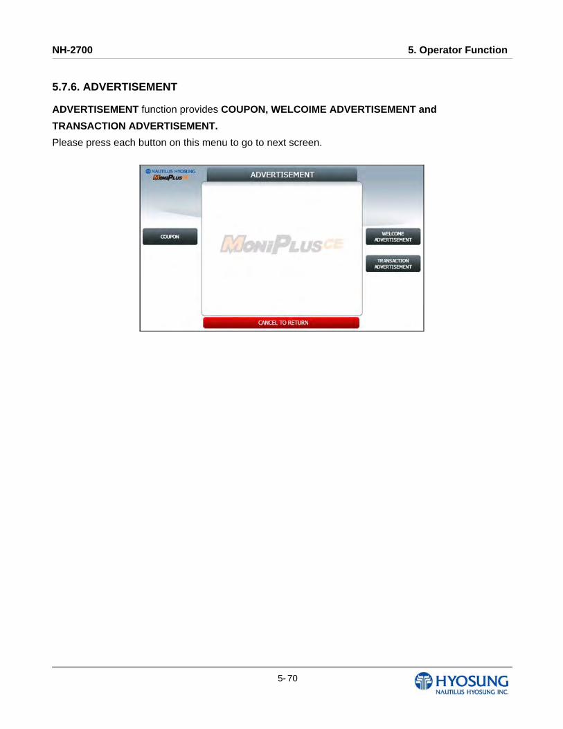
NH-2700 5. Operator Function
5- 70
5.7.6. ADVERTISEMENT
ADVERTISEMENT function provides COUPON, WELCOIME ADVERTISEMENT and
TRANSACTION ADVERTISEMENT.
Please press each button on this menu to go to next screen.

NH-2700 5. Operator Function
5- 71
5.7.6.1 COUPON Please press COUPON TYPE button to set up BASIC COUPON or ENHANCED COUPON.
If you set the BASIC COUPON and select COUPON SETTING button, BASIC COUPON setting
screen will be displayed.
BASIC COUPON supports 2line 39column, ENHANCED COUPON supports 16line 39column.
If you set the ENHANCED COUPON and select COUPON SETTING button, ENHANCED COUPON
setting screen will be displayed.
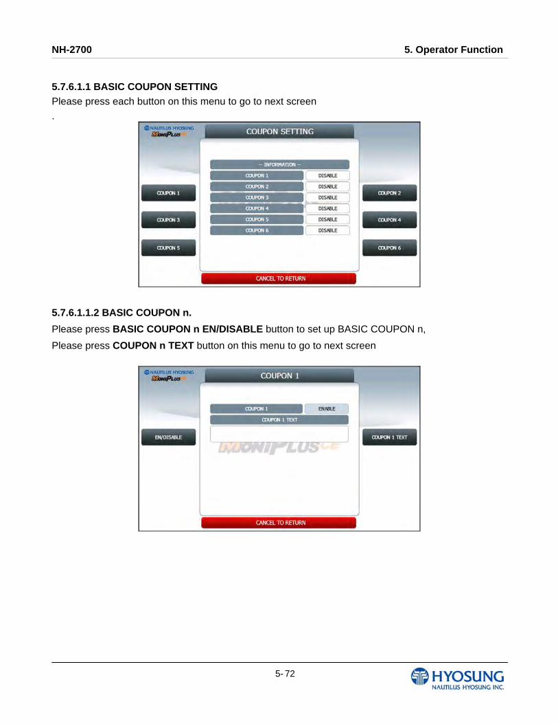
NH-2700 5. Operator Function
5- 72
5.7.6.1.1 BASIC COUPON SETTING Please press each button on this menu to go to next screen
.
5.7.6.1.1.2 BASIC COUPON n.
Please press BASIC COUPON n EN/DISABLE button to set up BASIC COUPON n,
Please press COUPON n TEXT button on this menu to go to next screen
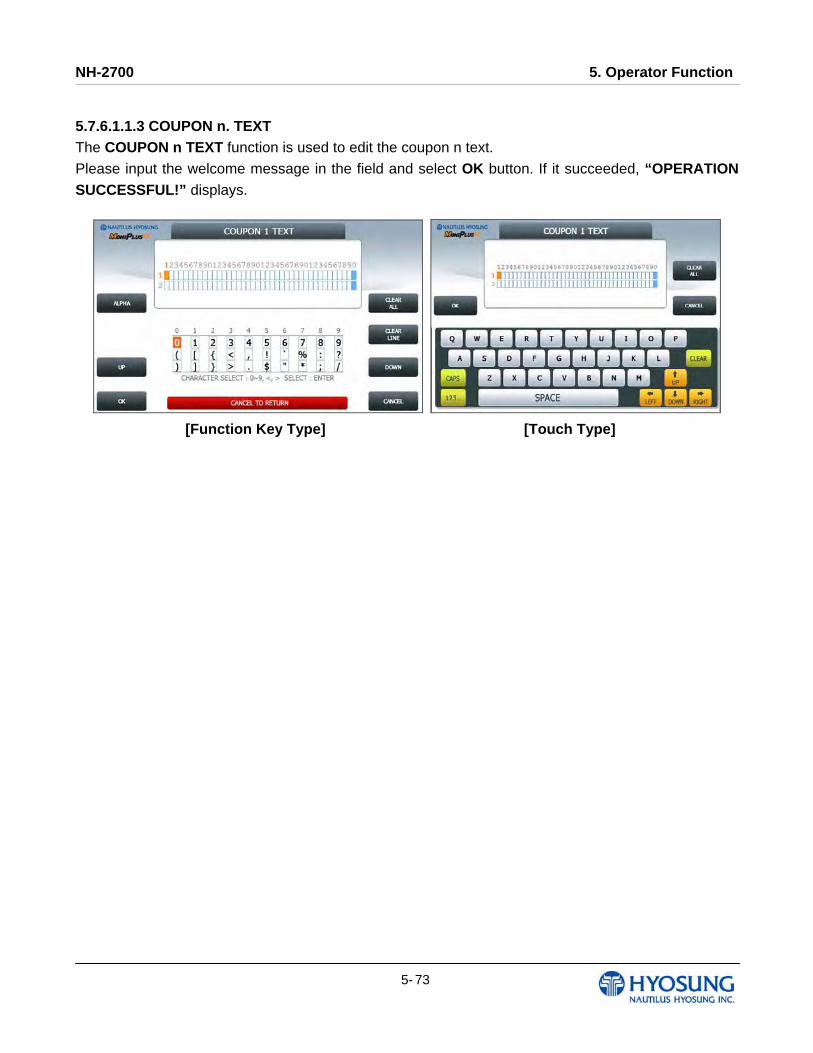
NH-2700 5. Operator Function
5- 73
5.7.6.1.1.3 COUPON n. TEXT The COUPON n TEXT function is used to edit the coupon n text.
Please input the welcome message in the field and select OK button. If it succeeded, “OPERATION SUCCESSFUL!” displays.
[Function Key Type] [Touch Type]
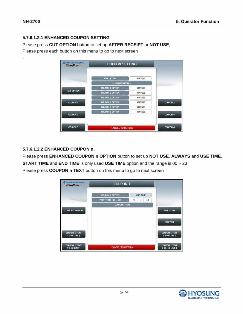
NH-2700 5. Operator Function
5- 74
5.7.6.1.2.1 ENHANCED COUPON SETTING
Please press CUT OPTION button to set up AFTER RECEIPT or NOT USE,
Please press each button on this menu to go to next screen
.
5.7.6.1.2.2 ENHANCED COUPON n.
Please press ENHANCED COUPON n OPTION button to set up NOT USE, ALWAYS and USE TIME.
START TIME and END TIME is only used USE TIME option and the range is 00 ~ 23
Please press COUPON n TEXT button on this menu to go to next screen

NH-2700 5. Operator Function
5- 75
5.7.6.1.2.3 ENHANCED COUPON n. TEXT The ENHANCED COUPON n TEXT function is used to edit the coupon n text.
Please input the welcome message in the field and select OK button. If it succeeded, “OPERATION
SUCCESSFUL!” displays.
[Function Key Type]

NH-2700 5. Operator Function
5- 76
[Touch Type]
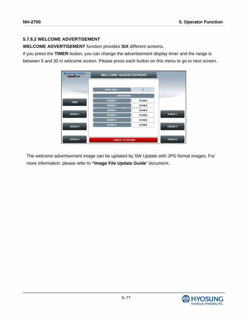
NH-2700 5. Operator Function
5- 77
5.7.6.2 WELCOME ADVERTISEMENT
WELCOME ADVERTISEMENT function provides SIX different screens.
If you press the TIMER button, you can change the advertisement display timer and the range is
between 5 and 30 in welcome screen. Please press each button on this menu to go to next screen.
The welcome advertisement image can be updated by SW Update with JPG format images. For
more information, please refer to “Image File Update Guide” document.
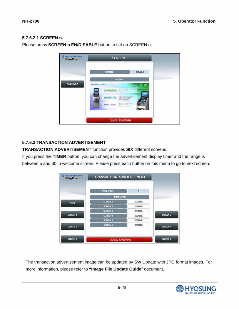
NH-2700 5. Operator Function
5- 78
5.7.6.2.1 SCREEN n.
Please press SCREEN n EN/DISABLE button to set up SCREEN n,
5.7.6.3 TRANSACTION ADVERTISEMENT
TRANSACTION ADVERTISEMENT function provides SIX different screens.
If you press the TIMER button, you can change the advertisement display timer and the range is
between 5 and 30 in welcome screen. Please press each button on this menu to go to next screen.
The transaction advertisement image can be updated by SW Update with JPG format images. For
more information, please refer to “Image File Update Guide” document.
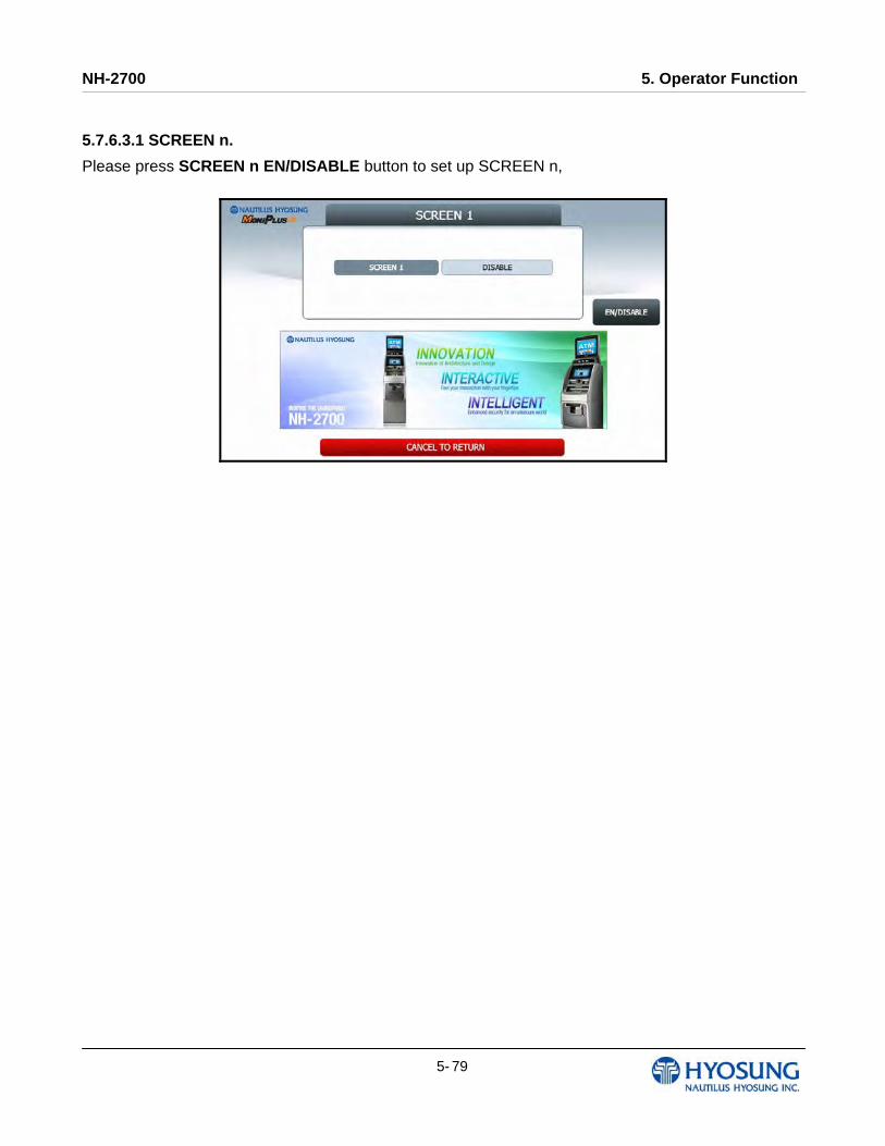
NH-2700 5. Operator Function
5- 79
5.7.6.3.1 SCREEN n.
Please press SCREEN n EN/DISABLE button to set up SCREEN n,
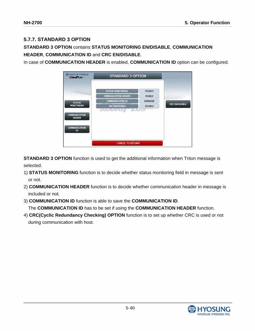
NH-2700 5. Operator Function
5- 80
5.7.7. STANDARD 3 OPTION
STANDARD 3 OPTION contains STATUS MONITORING EN/DISABLE, COMMUNICATION
HEADER, COMMUNICATION ID and CRC EN/DISABLE.
In case of COMMUNICATION HEADER is enabled, COMMUNICATION ID option can be configured.
STANDARD 3 OPTION function is used to get the additional information when Triton message is
selected.
1) STATUS MONITORING function is to decide whether status monitoring field in message is sent
or not.
2) COMMUNICATION HEADER function is to decide whether communication header in message is
included or not.
3) COMMUNICATION ID function is able to save the COMMUNICATION ID.
The COMMUNICATION ID has to be set if using the COMMUNICATION HEADER function.
4) CRC(Cyclic Redundancy Checking) OPTION function is to set up whether CRC is used or not
during communication with host.
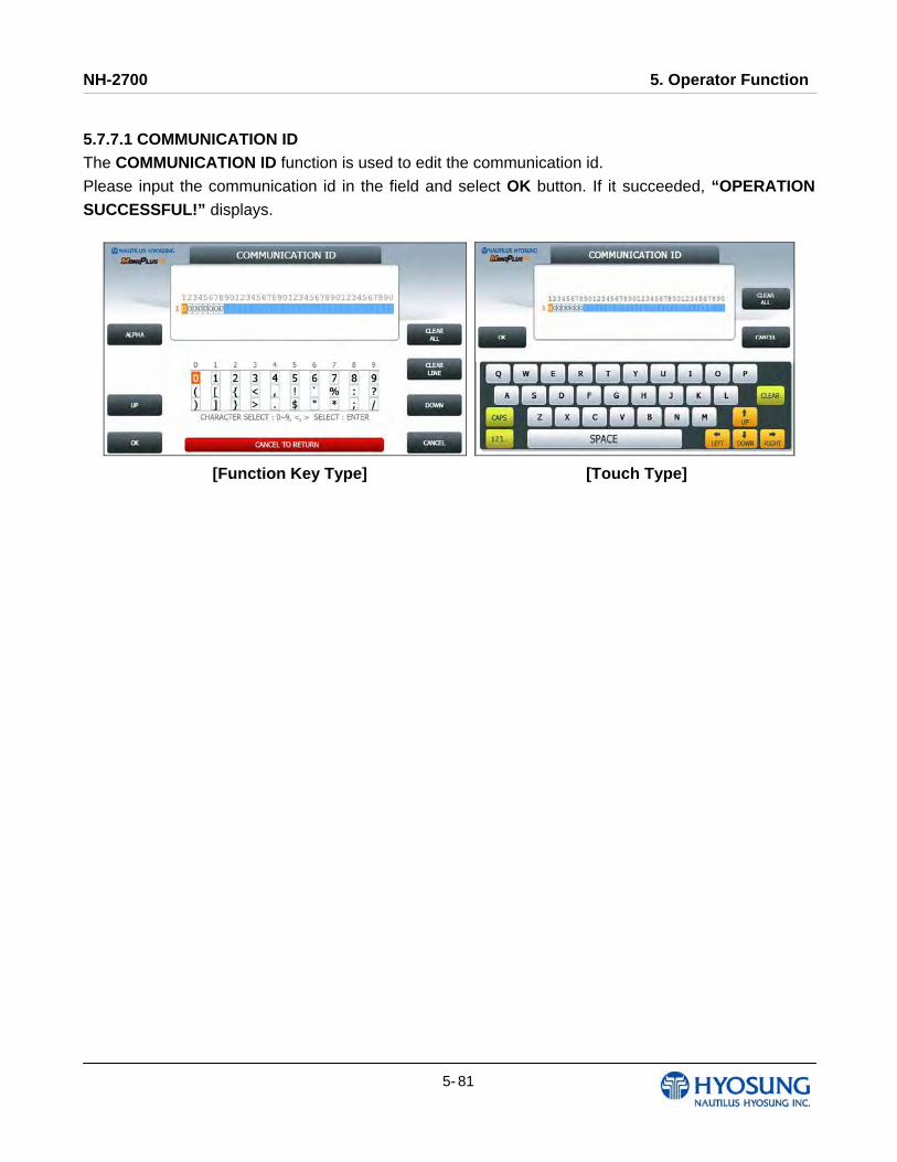
NH-2700 5. Operator Function
5- 81
5.7.7.1 COMMUNICATION ID The COMMUNICATION ID function is used to edit the communication id.
Please input the communication id in the field and select OK button. If it succeeded, “OPERATION SUCCESSFUL!” displays.
[Function Key Type] [Touch Type]
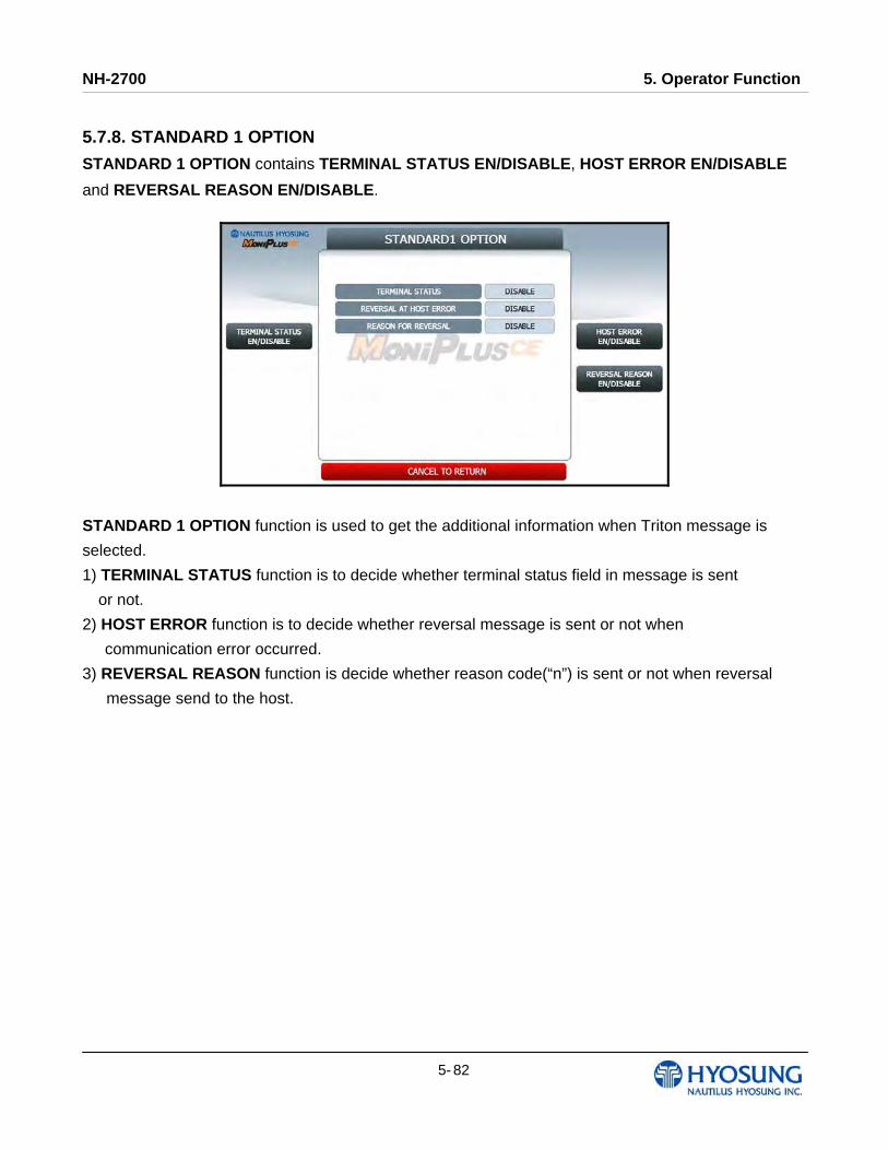
NH-2700 5. Operator Function
5- 82
5.7.8. STANDARD 1 OPTION
STANDARD 1 OPTION contains TERMINAL STATUS EN/DISABLE, HOST ERROR EN/DISABLE
and REVERSAL REASON EN/DISABLE.
STANDARD 1 OPTION function is used to get the additional information when Triton message is
selected.
1) TERMINAL STATUS function is to decide whether terminal status field in message is sent
or not.
2) HOST ERROR function is to decide whether reversal message is sent or not when
communication error occurred.
3) REVERSAL REASON function is decide whether reason code(“n”) is sent or not when reversal
message send to the host.
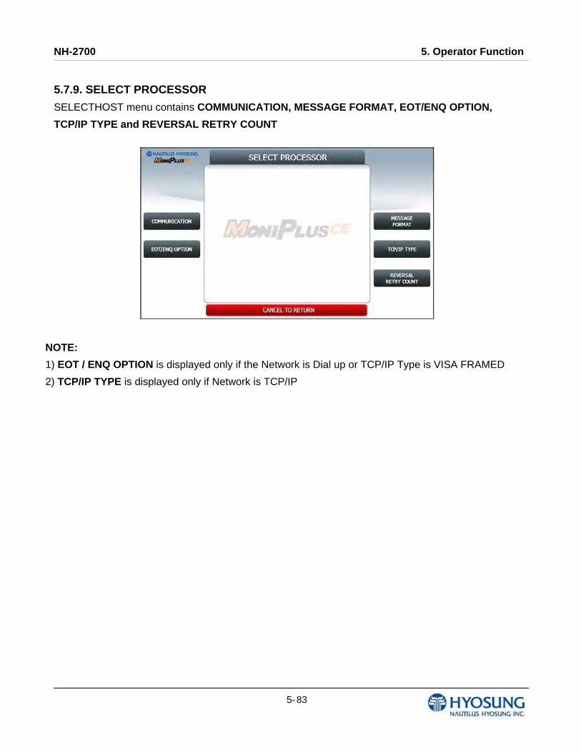
NH-2700 5. Operator Function
5- 83
5.7.9. SELECT PROCESSOR
SELECTHOST menu contains COMMUNICATION, MESSAGE FORMAT, EOT/ENQ OPTION,
TCP/IP TYPE and REVERSAL RETRY COUNT
NOTE:
1) EOT / ENQ OPTION is displayed only if the Network is Dial up or TCP/IP Type is VISA FRAMED
2) TCP/IP TYPE is displayed only if Network is TCP/IP
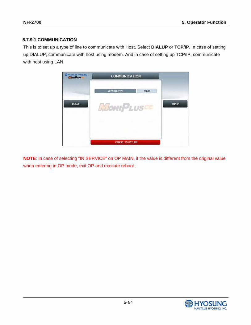
NH-2700 5. Operator Function
5- 84
5.7.9.1 COMMUNICATION
This is to set up a type of line to communicate with Host. Select DIALUP or TCP/IP. In case of setting
up DIALUP, communicate with host using modem. And in case of setting up TCP/IP, communicate
with host using LAN.
NOTE: In case of selecting “IN SERVICE” on OP MAIN, if the value is different from the original value
when entering in OP mode, exit OP and execute reboot.
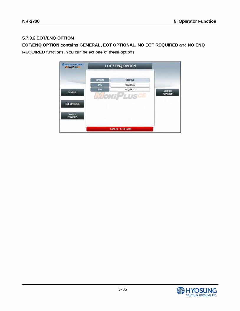
NH-2700 5. Operator Function
5- 85
5.7.9.2 EOT/ENQ OPTION
EOT/ENQ OPTION contains GENERAL, EOT OPTIONAL, NO EOT REQUIRED and NO ENQ
REQUIRED functions. You can select one of these options
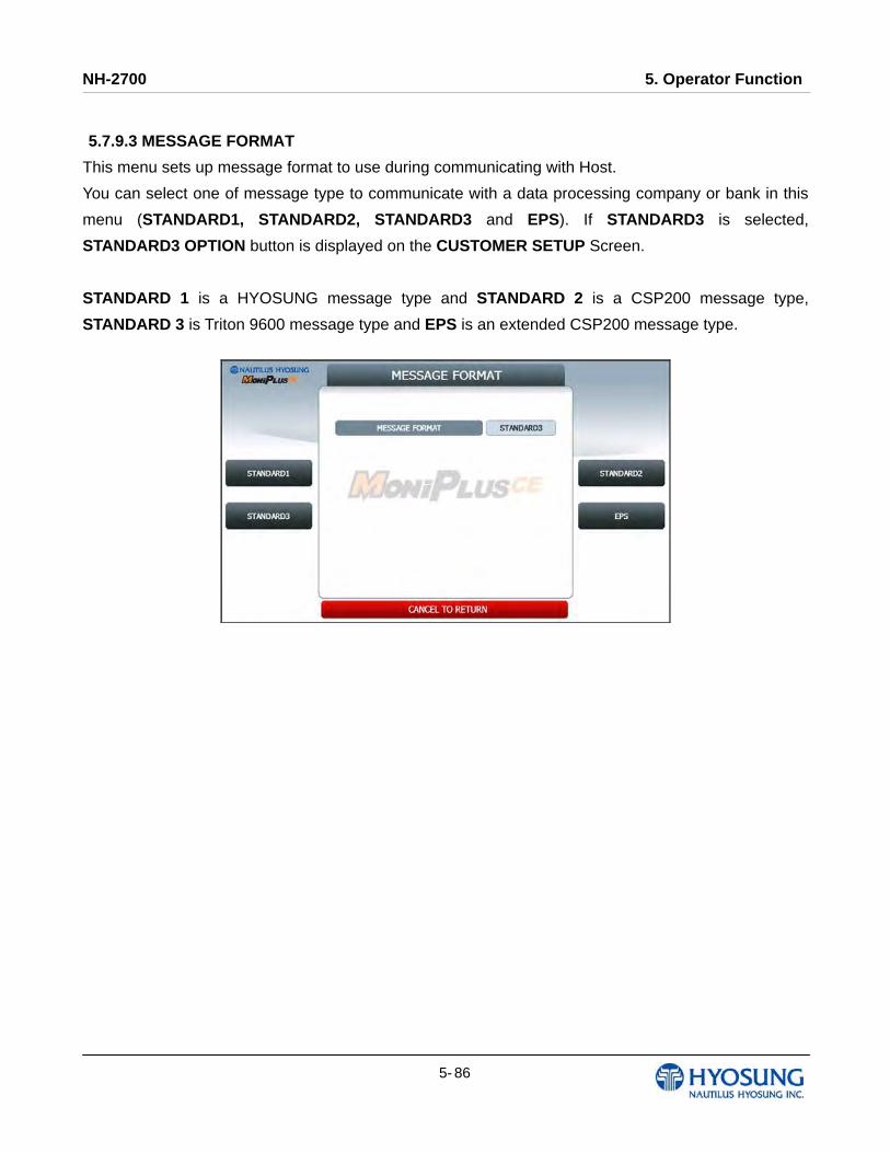
NH-2700 5. Operator Function
5- 86
5.7.9.3 MESSAGE FORMAT
This menu sets up message format to use during communicating with Host.
You can select one of message type to communicate with a data processing company or bank in this
menu (STANDARD1, STANDARD2, STANDARD3 and EPS). If STANDARD3 is selected,
STANDARD3 OPTION button is displayed on the CUSTOMER SETUP Screen.
STANDARD 1 is a HYOSUNG message type and STANDARD 2 is a CSP200 message type,
STANDARD 3 is Triton 9600 message type and EPS is an extended CSP200 message type.

NH-2700 5. Operator Function
5- 87
5.7.9.4 TCP/IP TYPE
In case of supporting TCP/IP, this is providing a function setting up communication flow to use when
communicating with host. In this menu, you can change TCP/IP TYPE and can decide whether
‘ENABLE’ or ‘DISABLE’ about SSL OPTION. There are three kind of TCP/IP type in this TCP/IP
COMMUNICATION menu
(STANDARD TCP/IP, VISA FRAMED TCP/IP, and ACK CONTROLLED TCP/IP).

NH-2700 5. Operator Function
5- 88
5.7.9.5 REVERSAL RETRY COUNT
REVERSAL RETRY COUNT function is used to set the try count of reversal transaction. CURRENT
REVERSAL RETRY COUNT displays count of current setting value. You can enter the count and then
press ENTER (or CONFIRM) if you want to change try count of reversal transaction. (You should ask
your DP about count of reversal transaction before change try count.)
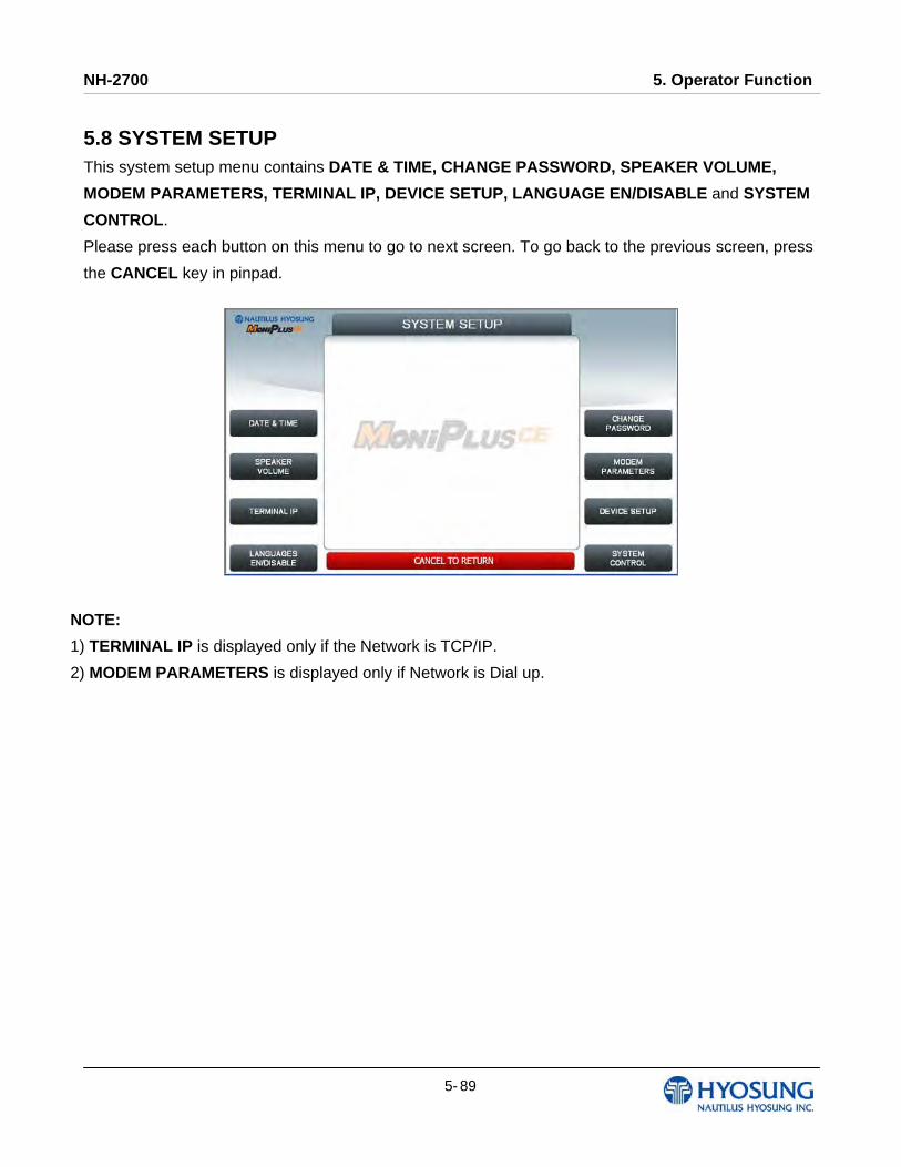
NH-2700 5. Operator Function
5- 89
5.8 SYSTEM SETUP This system setup menu contains DATE & TIME, CHANGE PASSWORD, SPEAKER VOLUME,
MODEM PARAMETERS, TERMINAL IP, DEVICE SETUP, LANGUAGE EN/DISABLE and SYSTEM
CONTROL.
Please press each button on this menu to go to next screen. To go back to the previous screen, press
the CANCEL key in pinpad.
NOTE:
1) TERMINAL IP is displayed only if the Network is TCP/IP.
2) MODEM PARAMETERS is displayed only if Network is Dial up.

NH-2700 5. Operator Function
5- 90
5.8.1 DATE & TIME You can set system date and time by pressing YEAR, HOUR, MONTH, MINUTE and DAY button. If
you press each menu, the cursor will be positioned and you can change the value. This value is saved
by pressing APPLY key, on the other hand, to go back to the previous screen, press the CANCEL key
in pinpad.
5.8.2 SPEAKER VOLUME The SPEAKER VOLUME function is used to set speaker volume by using DOWN and UP buttons. Once the button is pressed, ATM beeps.
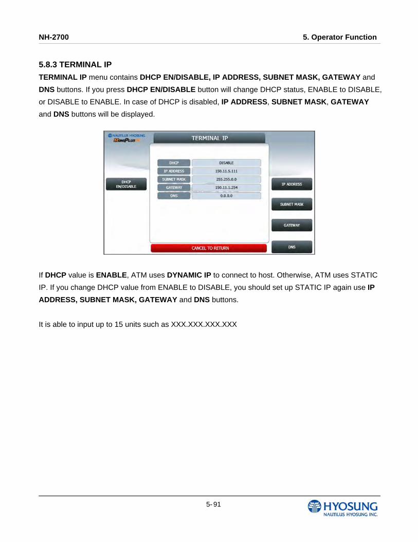
NH-2700 5. Operator Function
5- 91
5.8.3 TERMINAL IP
TERMINAL IP menu contains DHCP EN/DISABLE, IP ADDRESS, SUBNET MASK, GATEWAY and
DNS buttons. If you press DHCP EN/DISABLE button will change DHCP status, ENABLE to DISABLE,
or DISABLE to ENABLE. In case of DHCP is disabled, IP ADDRESS, SUBNET MASK, GATEWAY
and DNS buttons will be displayed.
If DHCP value is ENABLE, ATM uses DYNAMIC IP to connect to host. Otherwise, ATM uses STATIC
IP. If you change DHCP value from ENABLE to DISABLE, you should set up STATIC IP again use IP
ADDRESS, SUBNET MASK, GATEWAY and DNS buttons.
It is able to input up to 15 units such as XXX.XXX.XXX.XXX
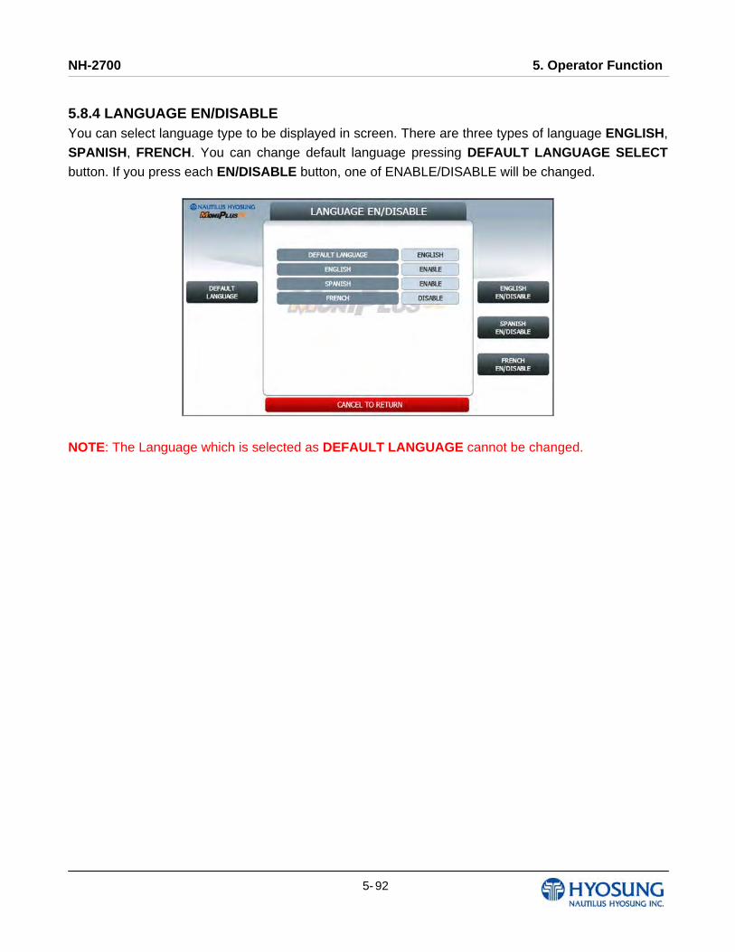
NH-2700 5. Operator Function
5- 92
5.8.4 LANGUAGE EN/DISABLE You can select language type to be displayed in screen. There are three types of language ENGLISH,
SPANISH, FRENCH. You can change default language pressing DEFAULT LANGUAGE SELECT
button. If you press each EN/DISABLE button, one of ENABLE/DISABLE will be changed.
NOTE: The Language which is selected as DEFAULT LANGUAGE cannot be changed.
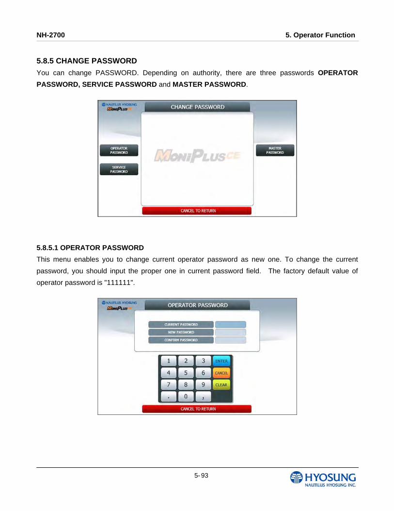
NH-2700 5. Operator Function
5- 93
5.8.5 CHANGE PASSWORD
You can change PASSWORD. Depending on authority, there are three passwords OPERATOR
PASSWORD, SERVICE PASSWORD and MASTER PASSWORD.
5.8.5.1 OPERATOR PASSWORD
This menu enables you to change current operator password as new one. To change the current
password, you should input the proper one in current password field. The factory default value of
operator password is "111111".
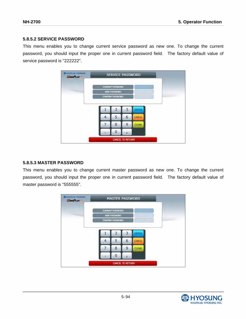
NH-2700 5. Operator Function
5- 94
5.8.5.2 SERVICE PASSWORD
This menu enables you to change current service password as new one. To change the current
password, you should input the proper one in current password field. The factory default value of
service password is "222222".
5.8.5.3 MASTER PASSWORD
This menu enables you to change current master password as new one. To change the current
password, you should input the proper one in current password field. The factory default value of
master password is "555555".
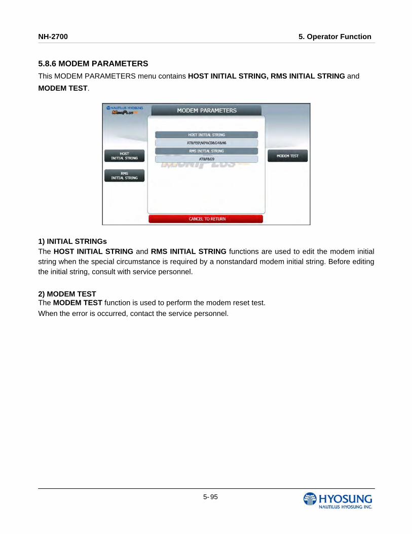
NH-2700 5. Operator Function
5- 95
5.8.6 MODEM PARAMETERS
This MODEM PARAMETERS menu contains HOST INITIAL STRING, RMS INITIAL STRING and
MODEM TEST.
1) INITIAL STRINGs The HOST INITIAL STRING and RMS INITIAL STRING functions are used to edit the modem initial string when the special circumstance is required by a nonstandard modem initial string. Before editing the initial string, consult with service personnel.
2) MODEM TEST The MODEM TEST function is used to perform the modem reset test.
When the error is occurred, contact the service personnel.
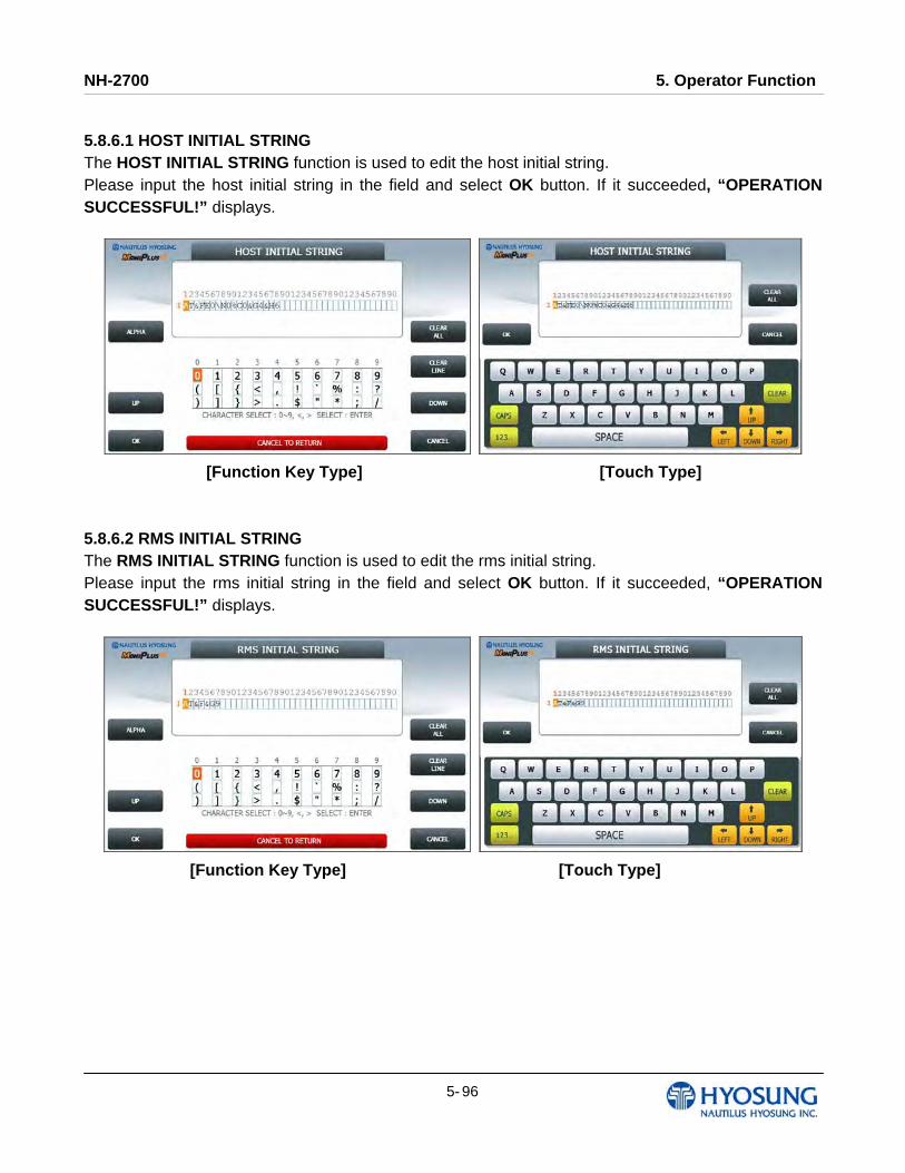
NH-2700 5. Operator Function
5- 96
5.8.6.1 HOST INITIAL STRING The HOST INITIAL STRING function is used to edit the host initial string. Please input the host initial string in the field and select OK button. If it succeeded, “OPERATION SUCCESSFUL!” displays.
[Function Key Type] [Touch Type]
5.8.6.2 RMS INITIAL STRING The RMS INITIAL STRING function is used to edit the rms initial string. Please input the rms initial string in the field and select OK button. If it succeeded, “OPERATION SUCCESSFUL!” displays.
[Function Key Type] [Touch Type]
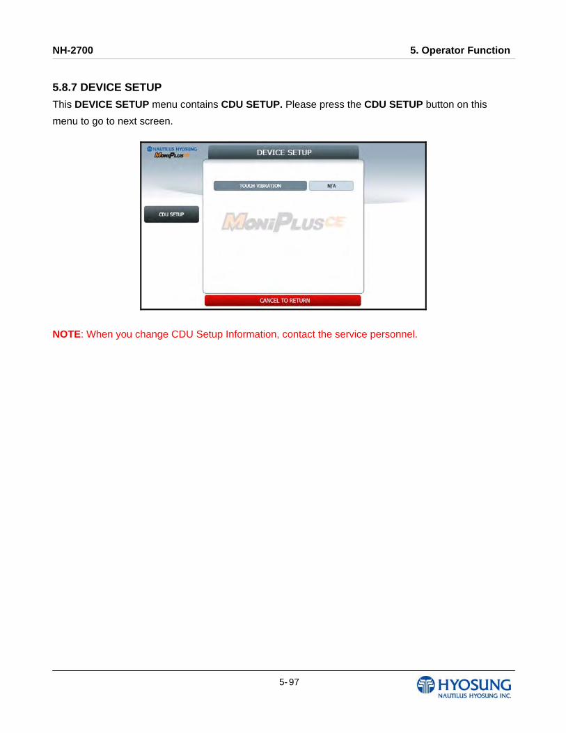
NH-2700 5. Operator Function
5- 97
5.8.7 DEVICE SETUP
This DEVICE SETUP menu contains CDU SETUP. Please press the CDU SETUP button on this
menu to go to next screen.
NOTE: When you change CDU Setup Information, contact the service personnel.
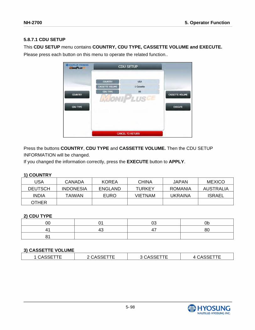
NH-2700 5. Operator Function
5- 98
5.8.7.1 CDU SETUP
This CDU SETUP menu contains COUNTRY, CDU TYPE, CASSETTE VOLUME and EXECUTE.
Please press each button on this menu to operate the related function..
Press the buttons COUNTRY, CDU TYPE and CASSETTE VOLUME. Then the CDU SETUP
INFORMATION will be changed.
If you changed the information correctly, press the EXECUTE button to APPLY.
1) COUNTRY
USA CANADA KOREA CHINA JAPAN MEXICO
DEUTSCH INDONESIA ENGLAND TURKEY ROMANIA AUSTRALIA
INDIA TAIWAN EURO VIETNAM UKRAINA ISRAEL
OTHER
2) CDU TYPE
00 01 03 0b
41 43 47 80
81
3) CASSETTE VOLUME
1 CASSETTE 2 CASSETTE 3 CASSETTE 4 CASSETTE
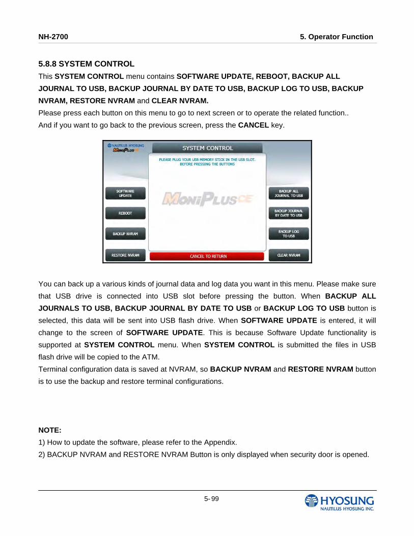
NH-2700 5. Operator Function
5- 99
5.8.8 SYSTEM CONTROL
This SYSTEM CONTROL menu contains SOFTWARE UPDATE, REBOOT, BACKUP ALL
JOURNAL TO USB, BACKUP JOURNAL BY DATE TO USB, BACKUP LOG TO USB, BACKUP
NVRAM, RESTORE NVRAM and CLEAR NVRAM.
Please press each button on this menu to go to next screen or to operate the related function..
And if you want to go back to the previous screen, press the CANCEL key.
You can back up a various kinds of journal data and log data you want in this menu. Please make sure
that USB drive is connected into USB slot before pressing the button. When BACKUP ALL
JOURNALS TO USB, BACKUP JOURNAL BY DATE TO USB or BACKUP LOG TO USB button is
selected, this data will be sent into USB flash drive. When SOFTWARE UPDATE is entered, it will
change to the screen of SOFTWARE UPDATE. This is because Software Update functionality is
supported at SYSTEM CONTROL menu. When SYSTEM CONTROL is submitted the files in USB
flash drive will be copied to the ATM.
Terminal configuration data is saved at NVRAM, so BACKUP NVRAM and RESTORE NVRAM button
is to use the backup and restore terminal configurations.
NOTE:
1) How to update the software, please refer to the Appendix.
2) BACKUP NVRAM and RESTORE NVRAM Button is only displayed when security door is opened.
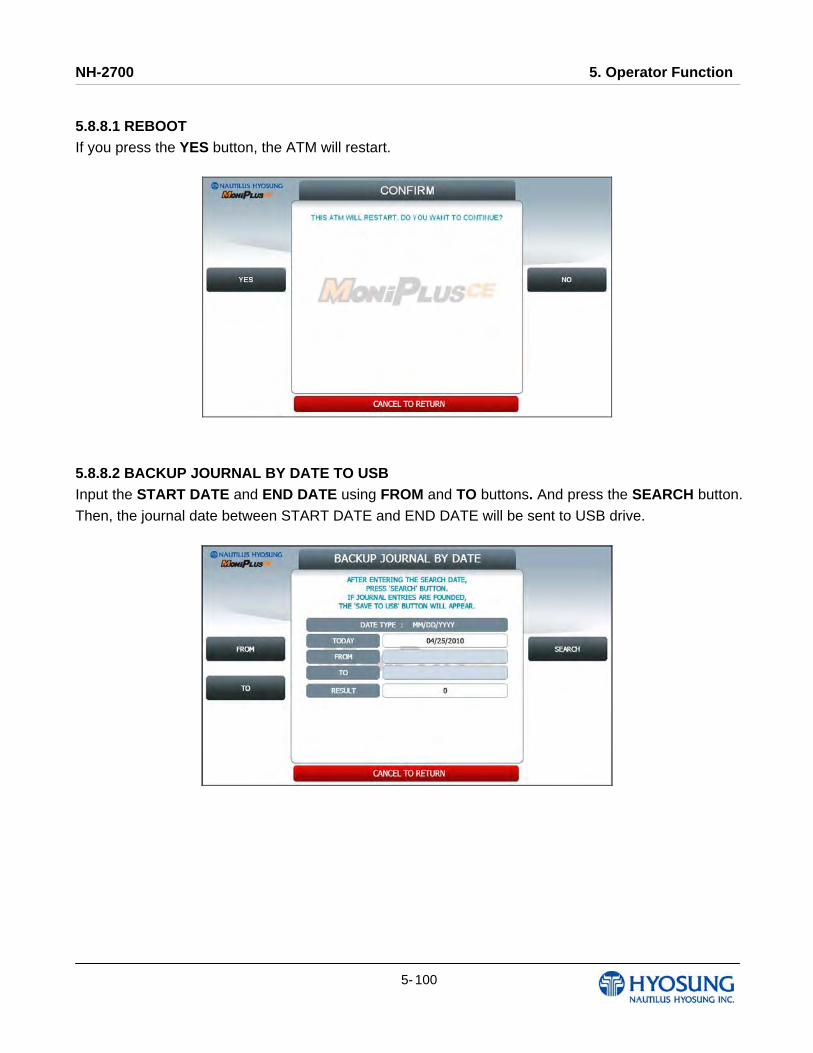
NH-2700 5. Operator Function
5- 100
5.8.8.1 REBOOT If you press the YES button, the ATM will restart.
5.8.8.2 BACKUP JOURNAL BY DATE TO USB Input the START DATE and END DATE using FROM and TO buttons. And press the SEARCH button.
Then, the journal date between START DATE and END DATE will be sent to USB drive.
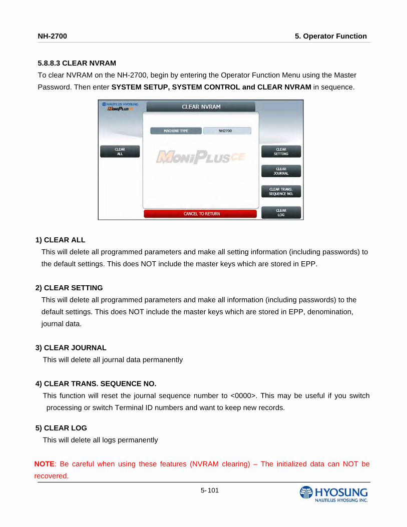
NH-2700 5. Operator Function
5- 101
5.8.8.3 CLEAR NVRAM
To clear NVRAM on the NH-2700, begin by entering the Operator Function Menu using the Master
Password. Then enter SYSTEM SETUP, SYSTEM CONTROL and CLEAR NVRAM in sequence.
1) CLEAR ALL
This will delete all programmed parameters and make all setting information (including passwords) to
the default settings. This does NOT include the master keys which are stored in EPP.
2) CLEAR SETTING
This will delete all programmed parameters and make all information (including passwords) to the
default settings. This does NOT include the master keys which are stored in EPP, denomination,
journal data.
3) CLEAR JOURNAL
This will delete all journal data permanently
4) CLEAR TRANS. SEQUENCE NO.
This function will reset the journal sequence number to <0000>. This may be useful if you switch
processing or switch Terminal ID numbers and want to keep new records.
5) CLEAR LOG
This will delete all logs permanently
NOTE: Be careful when using these features (NVRAM clearing) – The initialized data can NOT be
recovered.

NH-2700 5. Operator Function
5- 102
5.9 HOST SETUP
[DIALUP] This host setup menu contains KEY MANAGEMENT, TELEPHONE NUMBER, TERMINAL
ID, HEALTH CHECK MESSAGE, REMOTE MONITOR, ROUTING ID and AUTO DAY TOTAL
[TCP/IP] This host setup menu contains KEY MANAGEMENT, HOST ADDRESS, TERMINAL ID,
HEALTH CHECK MESSAGE, REMOTE MONITOR, ROUTING ID and AUTO DAY TOTAL.
Pressing function key beside menu button goes to next screen. To go back to the previous screen,
press the CANCEL key in pinpad.
[DIALUP]
[TCP/IP]
NOTE: ROUTING ID is displayed only if the message format is STANDARD1, 2 and EPS

NH-2700 5. Operator Function
5- 103
5.9.1 KEY MANAGEMENT
START SCREEN
Enter the PASSWORD 1 and PASSWORD 2 to execute KEY MANAGEMENT.
(Default PASSWORD 1 is ‘000000’. And default PASSWPRD 2 is ‘000000’ as well)
If you enter PASSWORD 1 and PASSWORD 2 correctly, the main screen of KEY MANAGEMENT will
be displayed as below.

NH-2700 5. Operator Function
5- 104
5.9.1.1 KEY MODE
The KEY MODE can be changed by pressing KEY MODE button. Write down the description here.
There are various kinds of KEY MODE. Those are [DES], [TDES], [DUAL MASTER KEY], [MAC],
[TDES, MAC], [TDES, TMAC], [UNIQUE KEY, DES], [UNIQUE KEY, TDES] and [UNIQUE KEY,
MAC].
Accessing the KEY INDEX
1) Select the HOST SETUP in the OPERATOR FUNCTION menu.
2) Select the KEY MANAGEMENT in the HOST SETUP menu.
3) Select the KEY MODE in the KEY MANAGEMENT menu. Change the KEY MODE..
5.9.1.2 KEY INDEX
The KEY INDEX function is used to set the KEY INDEX. The range is 0 to 15.
You can enter multiple master keys and have to select one of them. For security issue, DP may
change key index when they need to change keys. Accessing the KEY INDEX
1) Select the HOST SETUP in the OPERATOR FUNCTION menu.
2) Select the KEY MANAGEMENT in the HOST SETUP menu.
3) Select the KEY INDEX in the KEY MANAGEMENT menu. Input the KEY INDEX and press ENTER
key.

NH-2700 5. Operator Function
5- 105
5.9.1.3 CHECK KEY
The CHECK KEY function is used to display the check sum of all injected Keys. The key which is
displayed as “_______” means it is in empty state.
The authorized people can verify the injected key(s) with this menu after key injection.
Accessing the CHECK MASTER KEY 1) Select the HOST SETUP in the OPERATOR FUNCTION menu.
2) Select the KEY MANAGEMENT in the HOST SETUP menu.
3) Select the CHECK KEY in the KEY MANAGEMENT menu.
4) It will display the check sum of all injected master key.
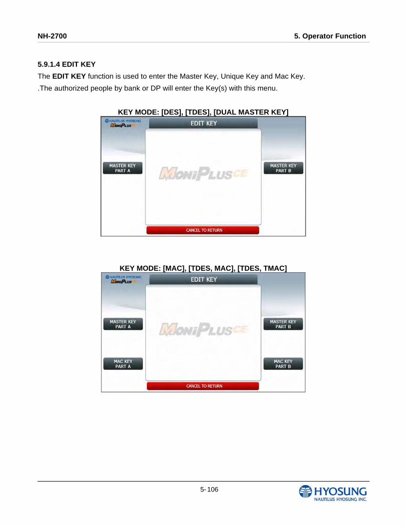
NH-2700 5. Operator Function
5- 106
5.9.1.4 EDIT KEY
The EDIT KEY function is used to enter the Master Key, Unique Key and Mac Key.
.The authorized people by bank or DP will enter the Key(s) with this menu.
KEY MODE: [DES], [TDES], [DUAL MASTER KEY]
KEY MODE: [MAC], [TDES, MAC], [TDES, TMAC]

NH-2700 5. Operator Function
5- 107
KEY MODE: [UNIQUE KEY, DES], [UNIQUE KEY, TDES]
KEY MODE: [UNIQUE KEY, MAC]
Accessing the EDIT KEY 1) Select the HOST SETUP in the OPERATOR FUNCTION menu.
2) Select the KEY MANAGEMENT in the HOST SETUP menu.
3) Select the EDIT KEY in the KEY MANAGEMENT menu.
NH-2700 5. Operator Function
5- 108
A. HOW TO EDIT MASTER KEY
1) Press MASTER KEY PART A button
2) Enter the MASTER KEY INDEX.
3) Enter the MASTER KEY PART A.
4) Verify the MASTER KEY PART A.
5) After inputting the MASTER KEY PART A, the CHECK SUM will be displayed. Press ENTER after confirming the check sum.
6) Press MASTER KEY PART B button
7) Enter the MASTER KEY INDEX.
8) Enter the MASTER KEY PART B
9) Verify the MASTER KEY PART B.
10) After inputting the MASTER KEY PART B, the CHECK SUM will be displayed. Press ENTER after confirming the check sum.
NOTE: You have to input the SAME KEY INDEX for MASTER KEY PART A and MASTER KEY PART B.
B. HOW TO EDIT UNIQUE KEY
1) Press UNIQUE KEY PART A button
2) Enter the UNIQUE KEY INDEX.
3) Enter the UNIQUE KEY PART A.
4) Verify the UNIQUE KEY PART A.
5) After inputting the UNIQUE KEY PART A, the CHECK SUM will be displayed. Press ENTER after confirming the check sum.
6) Press UNIQUE KEY PART B button
7) Enter the UNIQUE KEY INDEX.
8) Enter the UNIQUE KEY PART B
9) Verify the UNIQUE KEY PART B.
10) After inputting the UNIQUE KEY PART B, the CHECK SUM will be displayed. Press ENTER after confirming the check sum.
NOTE: You have to input the SAME KEY INDEX for UNIQUE KEY PART A and UNIQUE KEY PART B.

NH-2700 5. Operator Function
5- 109
B. HOW TO EDIT MAC KEY
1) Press MAC KEY PART A button
2) Enter the MAC KEY INDEX.
3) Enter the MAC KEY PART A.
4) Verify the MAC KEY PART A.
5) After inputting the MAC KEY PART A, the CHECK SUM will be displayed. Press ENTER after confirming the check sum.
6) Press MAC KEY PART B button
7) Enter the MAC KEY INDEX.
8) Enter the MAC KEY PART B
9) Verify the MAC KEY PART B.
10) After inputting the MAC KEY PART B, the CHECK SUM will be displayed. Press ENTER after confirming the check sum.
NOTE: You have to input the SAME KEY INDEX for MAC KEY PART A and MAC KEY PART B.

NH-2700 5. Operator Function
5- 110
5.9.1.5 SERIAL NUMBER
The SERIAL NUMBER function is used to insert the ATM machine number for RMS.
Accessing the SET MASTER KEY SERIAL NUMBER
1) Select the HOST SETUP in the OPERATOR FUNCTION menu.
2) Select the KEY MANAGEMENT in the HOST SETUP menu.
3) Select the SERIAL NUMBER in the KEY MANAGEMENT menu. And insert serial number.
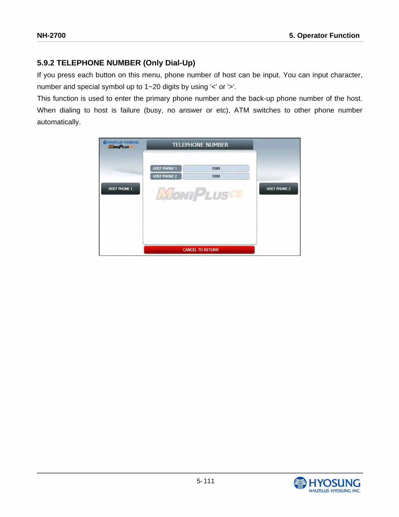
NH-2700 5. Operator Function
5- 111
5.9.2 TELEPHONE NUMBER (Only Dial-Up)
If you press each button on this menu, phone number of host can be input. You can input character,
number and special symbol up to 1~20 digits by using '<' or '>'.
This function is used to enter the primary phone number and the back-up phone number of the host.
When dialing to host is failure (busy, no answer or etc), ATM switches to other phone number
automatically.

NH-2700 5. Operator Function
5- 112
5.9.3 HOST ADDRESS HOST ADDRESS contains URL EN/DISABLE, HOST ADDRESS 1, PORT NUMBER 1, HOST ADDRESS 2 and PORT NUMBER 2.
Press PORT NUMBER 1 and PORT NUMBER 2 buttons, and then the values can be input on this
screen. These values can be saved by pressing ENTER key
HOST ADDRESS 1 and HOST ADDRESS 2 buttons go to the next page.
To go back to the previous screen, press the CANCEL key in pinpad.

NH-2700 5. Operator Function
5- 113
5.9.3.1 HOST ADDRESS 1
The HOST ADDRESS 1 function is used to edit the host address 1.
Please input the host address 1 in the field and select OK button. If it succeeded, “OPERATION
SUCCESSFUL!” displays.
[Function Key Type] [Touch Type]
5.9.3.2 HOST ADDRESS 2
The HOST ADDRESS 2 function is used to edit the host address 2.
Please input the host address 2 in the field and select OK button. If it succeeded, “OPERATION
SUCCESSFUL!” displays.
[Function Key Type] [Touch Type]

NH-2700 5. Operator Function
5- 114
5.9.4 TERMINAL ID
The TERMINAL ID function is used to edit the terminal id number of ATM.
Please input the terminal id in the field and select OK button. If it succeeded, “OPERATION
SUCCESSFUL!” displays.
Host will identify ATM by looking at terminal ID. Terminal ID will be included in host message and will
be printed on the receipt.
[Function Key Type] [Touch Type]
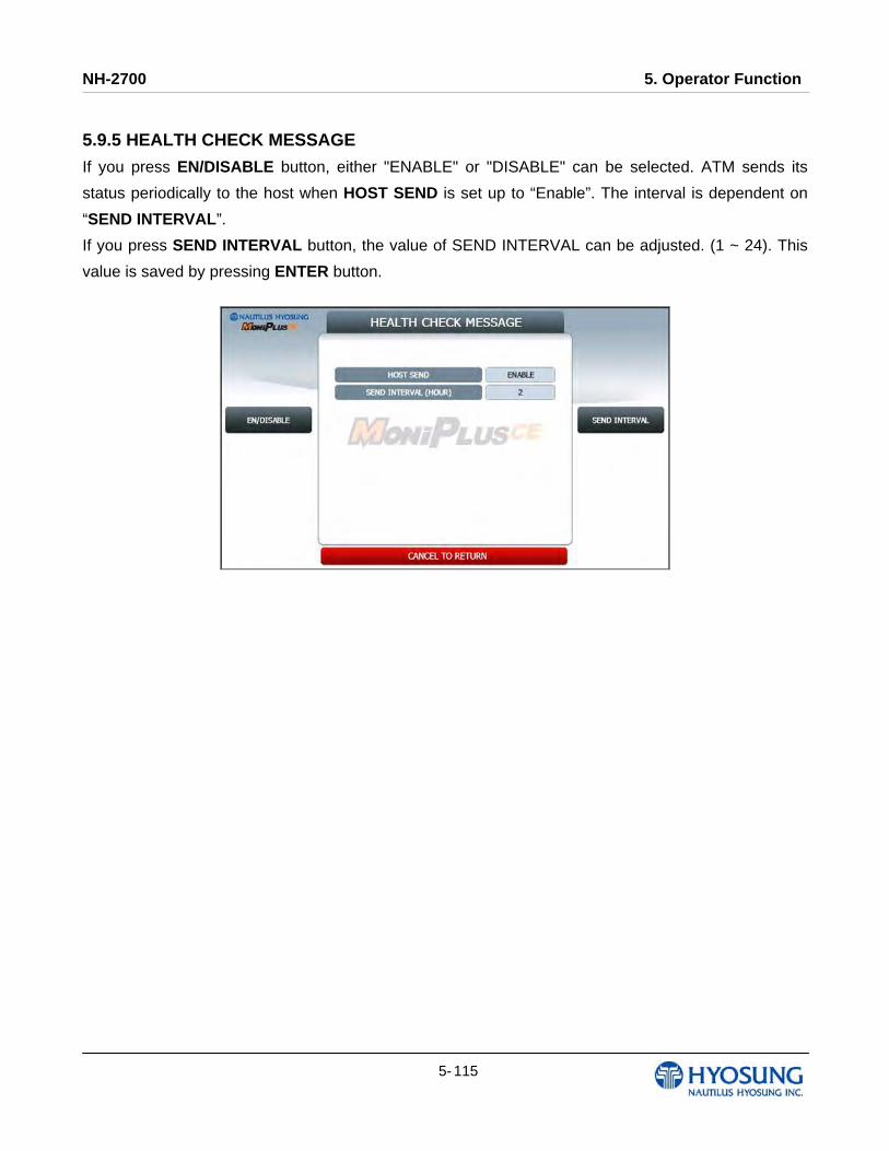
NH-2700 5. Operator Function
5- 115
5.9.5 HEALTH CHECK MESSAGE
If you press EN/DISABLE button, either "ENABLE" or "DISABLE" can be selected. ATM sends its
status periodically to the host when HOST SEND is set up to “Enable”. The interval is dependent on
“SEND INTERVAL”.
If you press SEND INTERVAL button, the value of SEND INTERVAL can be adjusted. (1 ~ 24). This
value is saved by pressing ENTER button.
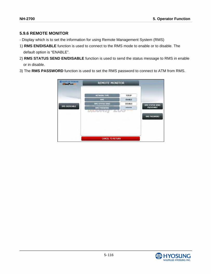
NH-2700 5. Operator Function
5- 116
5.9.6 REMOTE MONITOR
- Display which is to set the information for using Remote Management System (RMS)
1) RMS EN/DISABLE function is used to connect to the RMS mode to enable or to disable. The
default option is “ENABLE”.
2) RMS STATUS SEND EN/DISABLE function is used to send the status message to RMS in enable
or in disable.
3) The RMS PASSWORD function is used to set the RMS password to connect to ATM from RMS.
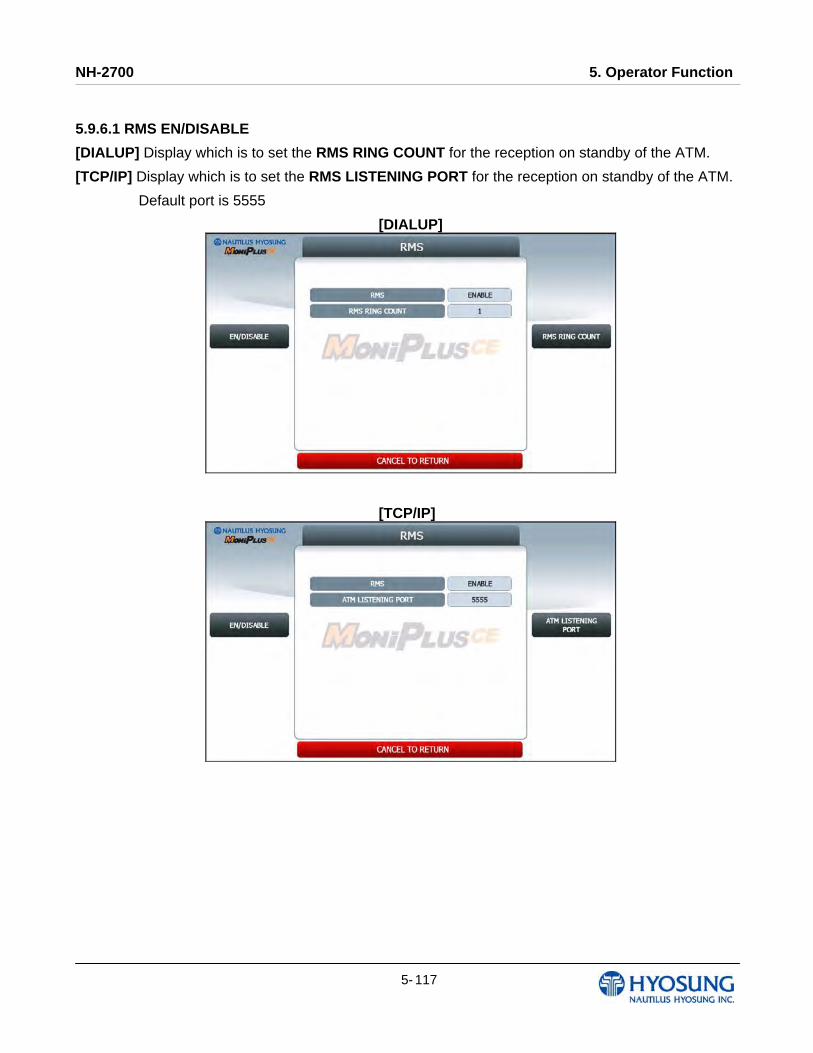
NH-2700 5. Operator Function
5- 117
5.9.6.1 RMS EN/DISABLE
[DIALUP] Display which is to set the RMS RING COUNT for the reception on standby of the ATM.
[TCP/IP] Display which is to set the RMS LISTENING PORT for the reception on standby of the ATM.
Default port is 5555
[DIALUP]
[TCP/IP]
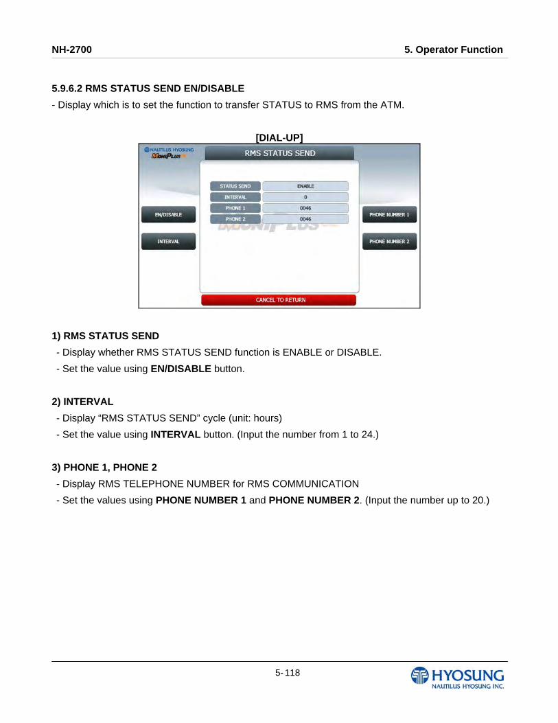
NH-2700 5. Operator Function
5- 118
5.9.6.2 RMS STATUS SEND EN/DISABLE
- Display which is to set the function to transfer STATUS to RMS from the ATM.
[DIAL-UP]
1) RMS STATUS SEND
- Display whether RMS STATUS SEND function is ENABLE or DISABLE.
- Set the value using EN/DISABLE button.
2) INTERVAL
- Display “RMS STATUS SEND” cycle (unit: hours)
- Set the value using INTERVAL button. (Input the number from 1 to 24.)
3) PHONE 1, PHONE 2
- Display RMS TELEPHONE NUMBER for RMS COMMUNICATION
- Set the values using PHONE NUMBER 1 and PHONE NUMBER 2. (Input the number up to 20.)
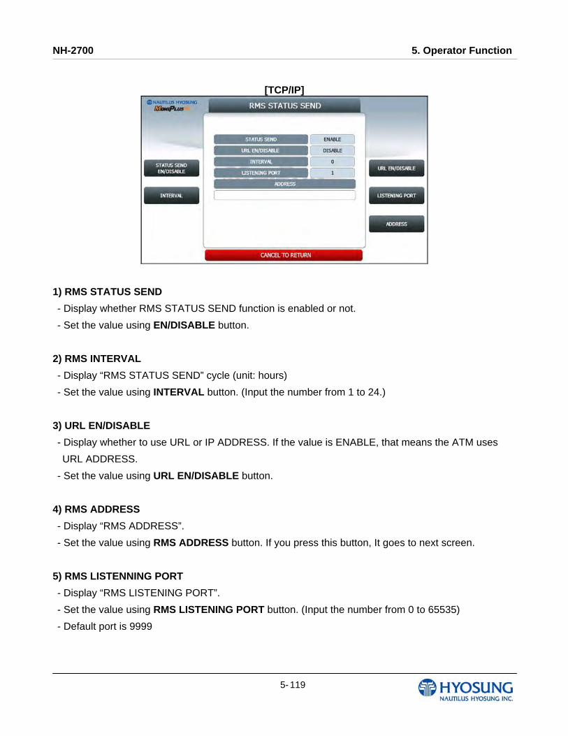
NH-2700 5. Operator Function
5- 119
[TCP/IP]
1) RMS STATUS SEND
- Display whether RMS STATUS SEND function is enabled or not.
- Set the value using EN/DISABLE button.
2) RMS INTERVAL
- Display “RMS STATUS SEND” cycle (unit: hours)
- Set the value using INTERVAL button. (Input the number from 1 to 24.)
3) URL EN/DISABLE
- Display whether to use URL or IP ADDRESS. If the value is ENABLE, that means the ATM uses
URL ADDRESS.
- Set the value using URL EN/DISABLE button.
4) RMS ADDRESS
- Display “RMS ADDRESS”.
- Set the value using RMS ADDRESS button. If you press this button, It goes to next screen.
5) RMS LISTENNING PORT
- Display “RMS LISTENING PORT”.
- Set the value using RMS LISTENING PORT button. (Input the number from 0 to 65535)
- Default port is 9999
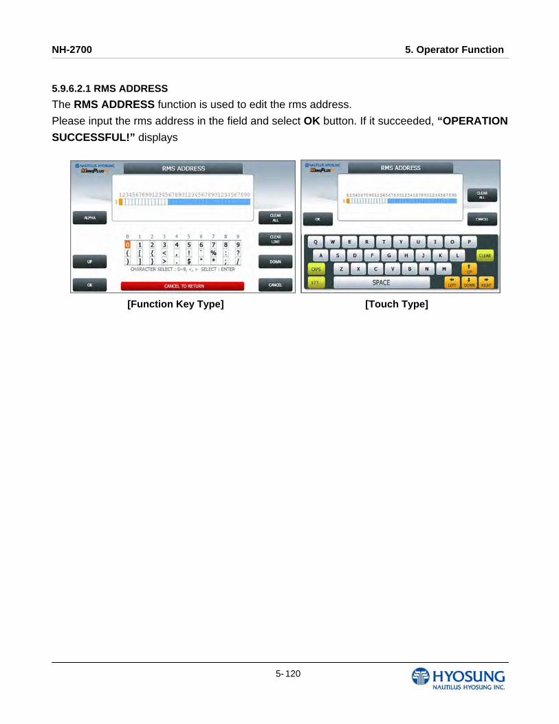
NH-2700 5. Operator Function
5- 120
5.9.6.2.1 RMS ADDRESS
The RMS ADDRESS function is used to edit the rms address.
Please input the rms address in the field and select OK button. If it succeeded, “OPERATION
SUCCESSFUL!” displays
[Function Key Type] [Touch Type]
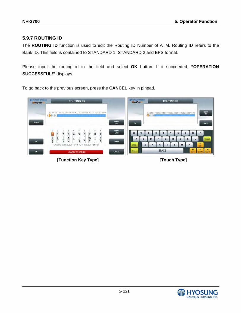
NH-2700 5. Operator Function
5- 121
5.9.7 ROUTING ID
The ROUTING ID function is used to edit the Routing ID Number of ATM. Routing ID refers to the
Bank ID. This field is contained to STANDARD 1, STANDARD 2 and EPS format.
Please input the routing id in the field and select OK button. If it succeeded, “OPERATION
SUCCESSFUL!” displays.
To go back to the previous screen, press the CANCEL key in pinpad.
[Function Key Type] [Touch Type]
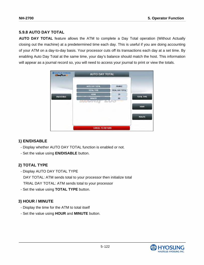
NH-2700 5. Operator Function
5- 122
5.9.8 AUTO DAY TOTAL
AUTO DAY TOTAL feature allows the ATM to complete a Day Total operation (Without Actually
closing out the machine) at a predetermined time each day. This is useful if you are doing accounting
of your ATM on a day-to-day basis. Your processor cuts off its transactions each day at a set time. By
enabling Auto Day Total at the same time, your day’s balance should match the host. This information
will appear as a journal record so, you will need to access your journal to print or view the totals.
1) EN/DISABLE
- Display whether AUTO DAY TOTAL function is enabled or not.
- Set the value using EN/DISABLE button.
2) TOTAL TYPE
- Display AUTO DAY TOTAL TYPE
DAY TOTAL: ATM sends total to your processor then initialize total
TRIAL DAY TOTAL: ATM sends total to your processor
- Set the value using TOTAL TYPE button.
3) HOUR / MINUTE
- Display the time for the ATM to total itself
- Set the value using HOUR and MINUTE button.
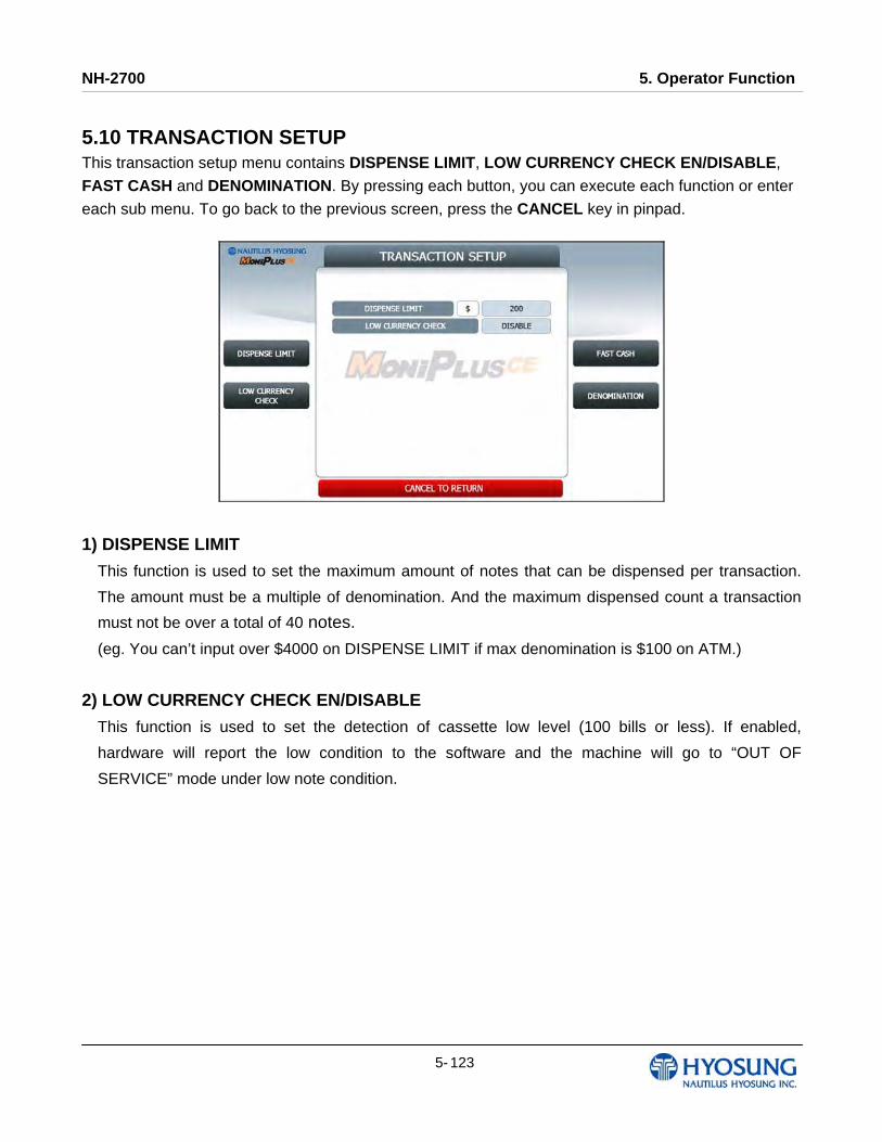
NH-2700 5. Operator Function
5- 123
5.10 TRANSACTION SETUP This transaction setup menu contains DISPENSE LIMIT, LOW CURRENCY CHECK EN/DISABLE,
FAST CASH and DENOMINATION. By pressing each button, you can execute each function or enter
each sub menu. To go back to the previous screen, press the CANCEL key in pinpad.
1) DISPENSE LIMIT
This function is used to set the maximum amount of notes that can be dispensed per transaction.
The amount must be a multiple of denomination. And the maximum dispensed count a transaction
must not be over a total of 40 notes.
(eg. You can’t input over $4000 on DISPENSE LIMIT if max denomination is $100 on ATM.)
2) LOW CURRENCY CHECK EN/DISABLE
This function is used to set the detection of cassette low level (100 bills or less). If enabled,
hardware will report the low condition to the software and the machine will go to “OUT OF
SERVICE” mode under low note condition.
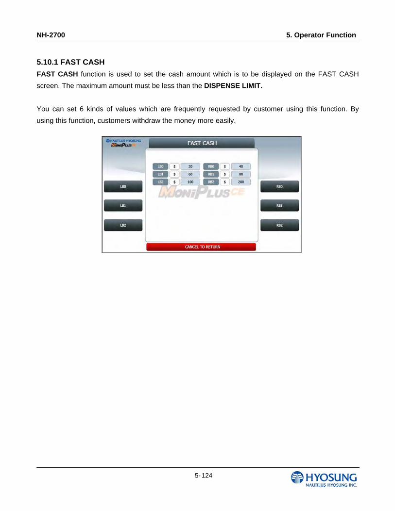
NH-2700 5. Operator Function
5- 124
5.10.1 FAST CASH
FAST CASH function is used to set the cash amount which is to be displayed on the FAST CASH
screen. The maximum amount must be less than the DISPENSE LIMIT.
You can set 6 kinds of values which are frequently requested by customer using this function. By
using this function, customers withdraw the money more easily.
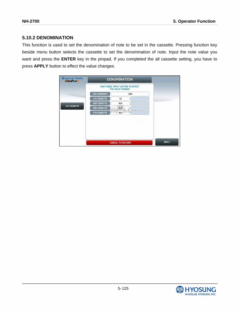
NH-2700 5. Operator Function
5- 125
5.10.2 DENOMINATION
This function is used to set the denomination of note to be set in the cassette. Pressing function key
beside menu button selects the cassette to set the denomination of note. Input the note value you
want and press the ENTER key in the pinpad. If you completed the all cassette setting, you have to
press APPLY button to effect the value changes.

NH-2700 5. Operator Function
5- 126
5.11 SITE MAP
This site map shows the structure of the operator menu tree to aid in searching menu. In case of touch
type, if you press each menu SETTLEMENT, JOURNAL, REPORT, DIAGNOSTICS, CUSTOMER
SETUP, SYSTEM SETUP, HOST SETUP or TRANSACTION SETUP, then it will enter each sub-
menu.
5.12 QUICK REPLENISH This menu provides convenience for replenishing note at once. This menu consists of DAY TOTAL, CASSETTE TOTAL, ADD CASH and RESULT.
If you press YES button, the QUICK REPLENISH will start.
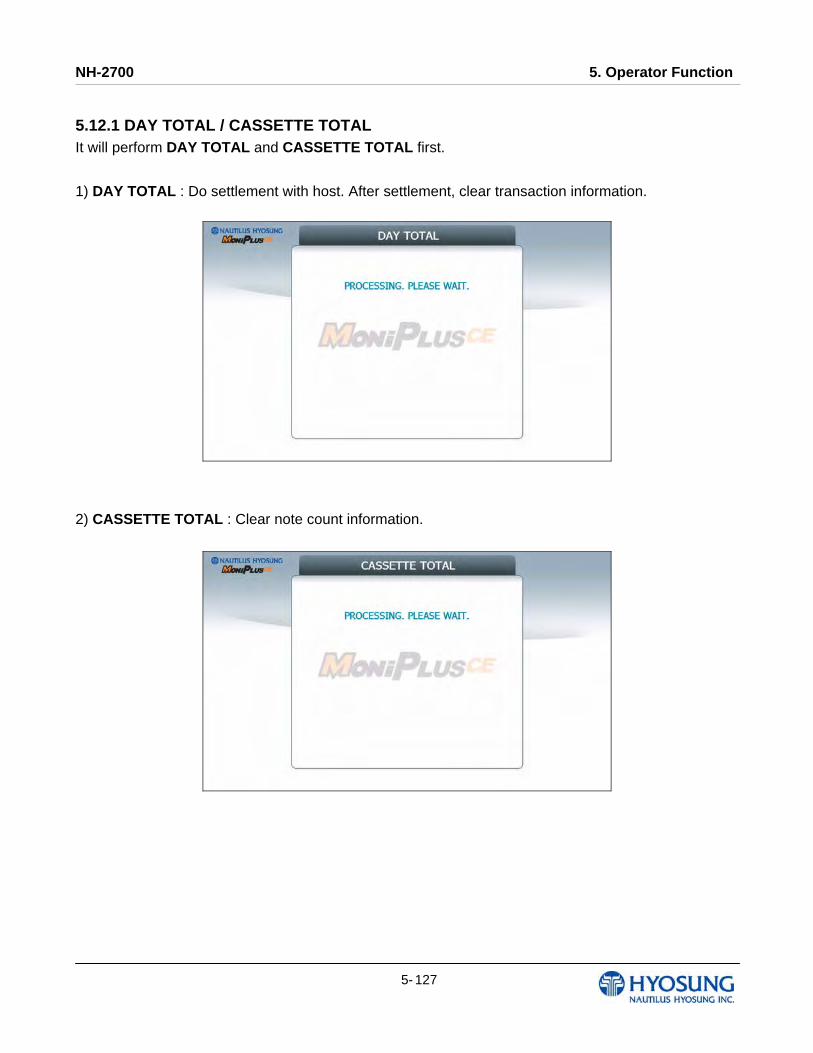
NH-2700 5. Operator Function
5- 127
5.12.1 DAY TOTAL / CASSETTE TOTAL
It will perform DAY TOTAL and CASSETTE TOTAL first.
1) DAY TOTAL : Do settlement with host. After settlement, clear transaction information.
2) CASSETTE TOTAL : Clear note count information.
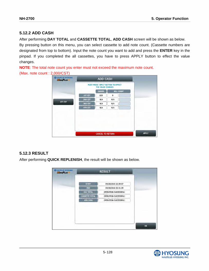
NH-2700 5. Operator Function
5- 128
5.12.2 ADD CASH
After performing DAY TOTAL and CASSETTE TOTAL, ADD CASH screen will be shown as below.
By pressing button on this menu, you can select cassette to add note count. (Cassette numbers are
designated from top to bottom). Input the note count you want to add and press the ENTER key in the
pinpad. If you completed the all cassettes, you have to press APPLY button to effect the value
changes.
NOTE: The total note count you enter must not exceed the maximum note count.
(Max. note count : 2,000/CST)
5.12.3 RESULT
After performing QUICK REPLENISH, the result will be shown as below.
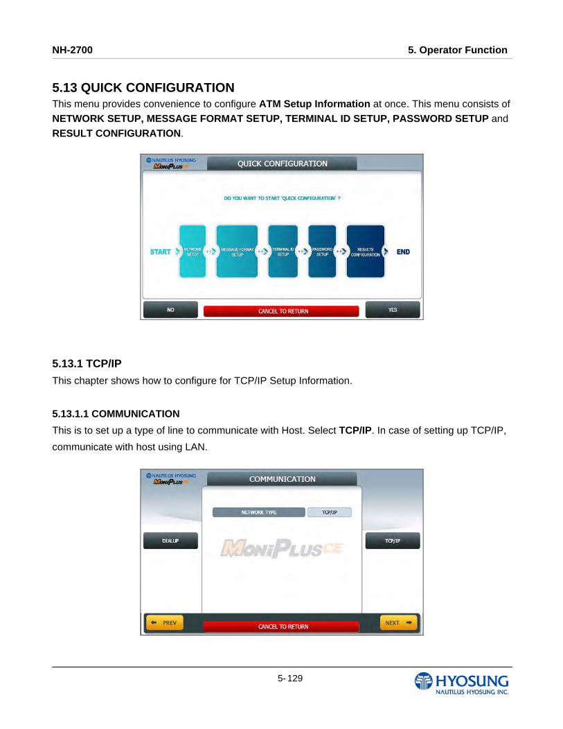
NH-2700 5. Operator Function
5- 129
5.13 QUICK CONFIGURATION This menu provides convenience to configure ATM Setup Information at once. This menu consists of
NETWORK SETUP, MESSAGE FORMAT SETUP, TERMINAL ID SETUP, PASSWORD SETUP and RESULT CONFIGURATION.
5.13.1 TCP/IP
This chapter shows how to configure for TCP/IP Setup Information.
5.13.1.1 COMMUNICATION
This is to set up a type of line to communicate with Host. Select TCP/IP. In case of setting up TCP/IP,
communicate with host using LAN.

NH-2700 5. Operator Function
5- 130
5.13.1.2 TCP/IP TYPE
In case of supporting TCP/IP, this is providing a function setting up communication flow to use when
communicating with host. In this menu, you can change TCP/IP TYPE and can decide whether
‘ENABLE’ or ‘DISABLE’ about SSL OPTION. There are three kind of TCP/IP type in this TCP/IP
COMMUNICATION menu
(STANDARD TCP/IP, VISA FRAMED TCP/IP, and ACK CONTROLLED TCP/IP).
NOTE: When you press NEXT button, if you configured TCP/IP TYPE to VISA FRAMED, then it goes
to Section No 5.13.1.3. If not, then it goes to Section No. 5.13.1.4.
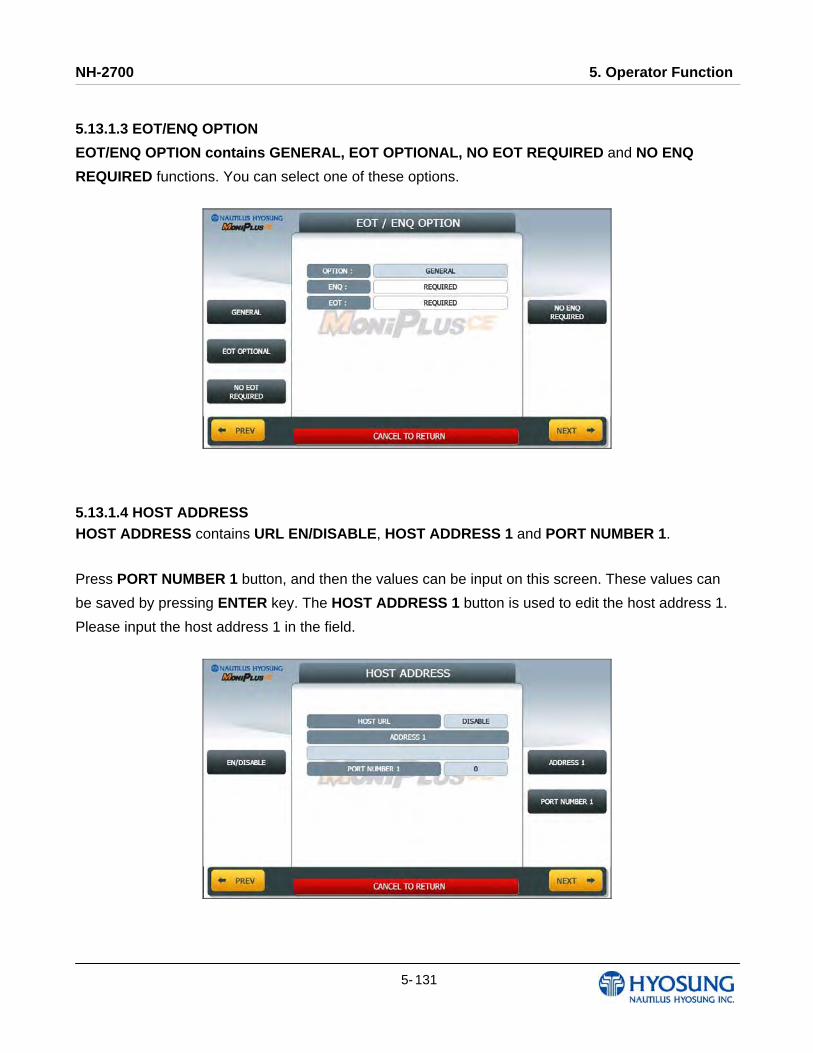
NH-2700 5. Operator Function
5- 131
5.13.1.3 EOT/ENQ OPTION
EOT/ENQ OPTION contains GENERAL, EOT OPTIONAL, NO EOT REQUIRED and NO ENQ
REQUIRED functions. You can select one of these options.
5.13.1.4 HOST ADDRESS HOST ADDRESS contains URL EN/DISABLE, HOST ADDRESS 1 and PORT NUMBER 1.
Press PORT NUMBER 1 button, and then the values can be input on this screen. These values can
be saved by pressing ENTER key. The HOST ADDRESS 1 button is used to edit the host address 1.
Please input the host address 1 in the field.
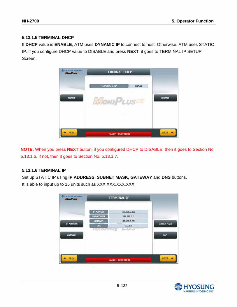
NH-2700 5. Operator Function
5- 132
5.13.1.5 TERMINAL DHCP
If DHCP value is ENABLE, ATM uses DYNAMIC IP to connect to host. Otherwise, ATM uses STATIC
IP. If you configure DHCP value to DISABLE and press NEXT, it goes to TERMINAL IP SETUP
Screen.
NOTE: When you press NEXT button, if you configured DHCP to DISABLE, then it goes to Section No
5.13.1.6. If not, then it goes to Section No. 5.13.1.7.
5.13.1.6 TERMINAL IP
Set up STATIC IP using IP ADDRESS, SUBNET MASK, GATEWAY and DNS buttons.
It is able to input up to 15 units such as XXX.XXX.XXX.XXX
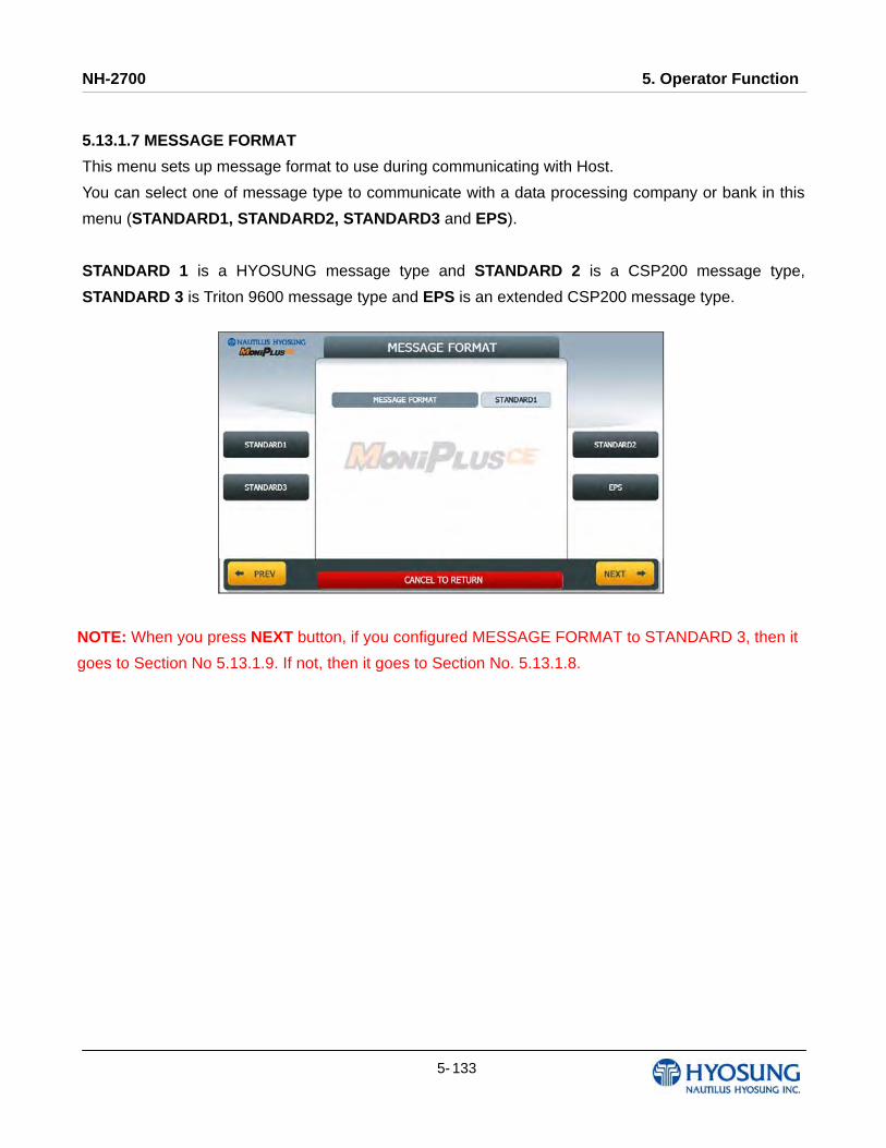
NH-2700 5. Operator Function
5- 133
5.13.1.7 MESSAGE FORMAT
This menu sets up message format to use during communicating with Host.
You can select one of message type to communicate with a data processing company or bank in this
menu (STANDARD1, STANDARD2, STANDARD3 and EPS).
STANDARD 1 is a HYOSUNG message type and STANDARD 2 is a CSP200 message type,
STANDARD 3 is Triton 9600 message type and EPS is an extended CSP200 message type.
NOTE: When you press NEXT button, if you configured MESSAGE FORMAT to STANDARD 3, then it
goes to Section No 5.13.1.9. If not, then it goes to Section No. 5.13.1.8.
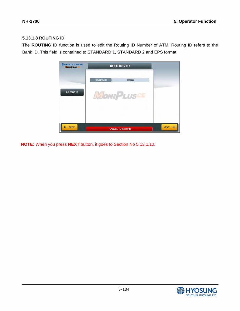
NH-2700 5. Operator Function
5- 134
5.13.1.8 ROUTING ID
The ROUTING ID function is used to edit the Routing ID Number of ATM. Routing ID refers to the
Bank ID. This field is contained to STANDARD 1, STANDARD 2 and EPS format.
NOTE: When you press NEXT button, it goes to Section No 5.13.1.10.

NH-2700 5. Operator Function
5- 135
5.13.1.9 STANDARD3 OPTION
STANDARD 3 OPTION contains STATUS MONITORING EN/DISABLE, COMMUNICATION
HEADER, COMMUNICATION ID and CRC EN/DISABLE.
In case of COMMUNICATION HEADER is enabled, CRC EN/DISABLE option can be configured.
STANDARD 3 OPTION function is used to get the additional information when Triton message is
selected.
1) STATUS MONITORING function is to decide whether status monitoring field in message is sent
or not.
2) COMMUNICATION HEADER function is to decide whether communication header in message is
included or not.
3) COMMUNICATION ID function is able to save the COMMUNICATION ID.
The COMMUNICATION ID has to be set if using the COMMUNICATION HEADER function.
4) CRC(Cyclic Redundancy Checking) OPTION function is to set up whether CRC is used or not
during communication with host.
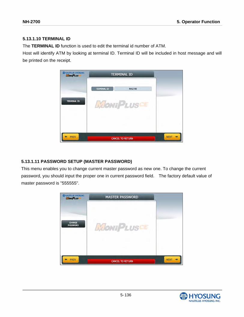
NH-2700 5. Operator Function
5- 136
5.13.1.10 TERMINAL ID
The TERMINAL ID function is used to edit the terminal id number of ATM.
Host will identify ATM by looking at terminal ID. Terminal ID will be included in host message and will
be printed on the receipt.
5.13.1.11 PASSWORD SETUP (MASTER PASSWORD)
This menu enables you to change current master password as new one. To change the current
password, you should input the proper one in current password field. The factory default value of
master password is "555555".

NH-2700 5. Operator Function
5- 137
5.13.1.12 RESULT
After performing QUICK CONFIGURATION, the result will be shown as below.
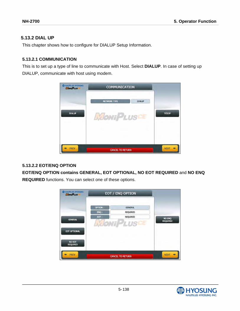
NH-2700 5. Operator Function
5- 138
5.13.2 DIAL UP
This chapter shows how to configure for DIALUP Setup Information.
5.13.2.1 COMMUNICATION
This is to set up a type of line to communicate with Host. Select DIALUP. In case of setting up
DIALUP, communicate with host using modem.
5.13.2.2 EOT/ENQ OPTION
EOT/ENQ OPTION contains GENERAL, EOT OPTIONAL, NO EOT REQUIRED and NO ENQ
REQUIRED functions. You can select one of these options.
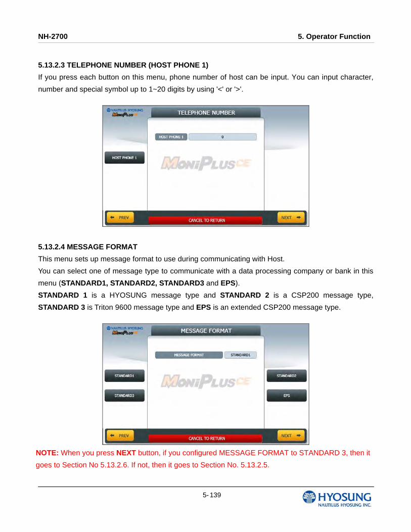
NH-2700 5. Operator Function
5- 139
5.13.2.3 TELEPHONE NUMBER (HOST PHONE 1)
If you press each button on this menu, phone number of host can be input. You can input character,
number and special symbol up to 1~20 digits by using '<' or '>'.
5.13.2.4 MESSAGE FORMAT
This menu sets up message format to use during communicating with Host.
You can select one of message type to communicate with a data processing company or bank in this
menu (STANDARD1, STANDARD2, STANDARD3 and EPS).
STANDARD 1 is a HYOSUNG message type and STANDARD 2 is a CSP200 message type,
STANDARD 3 is Triton 9600 message type and EPS is an extended CSP200 message type.
NOTE: When you press NEXT button, if you configured MESSAGE FORMAT to STANDARD 3, then it
goes to Section No 5.13.2.6. If not, then it goes to Section No. 5.13.2.5.
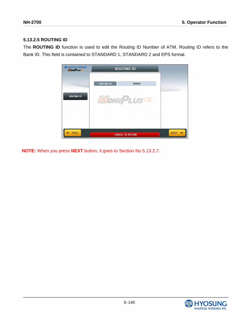
NH-2700 5. Operator Function
5- 140
5.13.2.5 ROUTING ID
The ROUTING ID function is used to edit the Routing ID Number of ATM. Routing ID refers to the
Bank ID. This field is contained to STANDARD 1, STANDARD 2 and EPS format.
NOTE: When you press NEXT button, it goes to Section No 5.13.2.7.
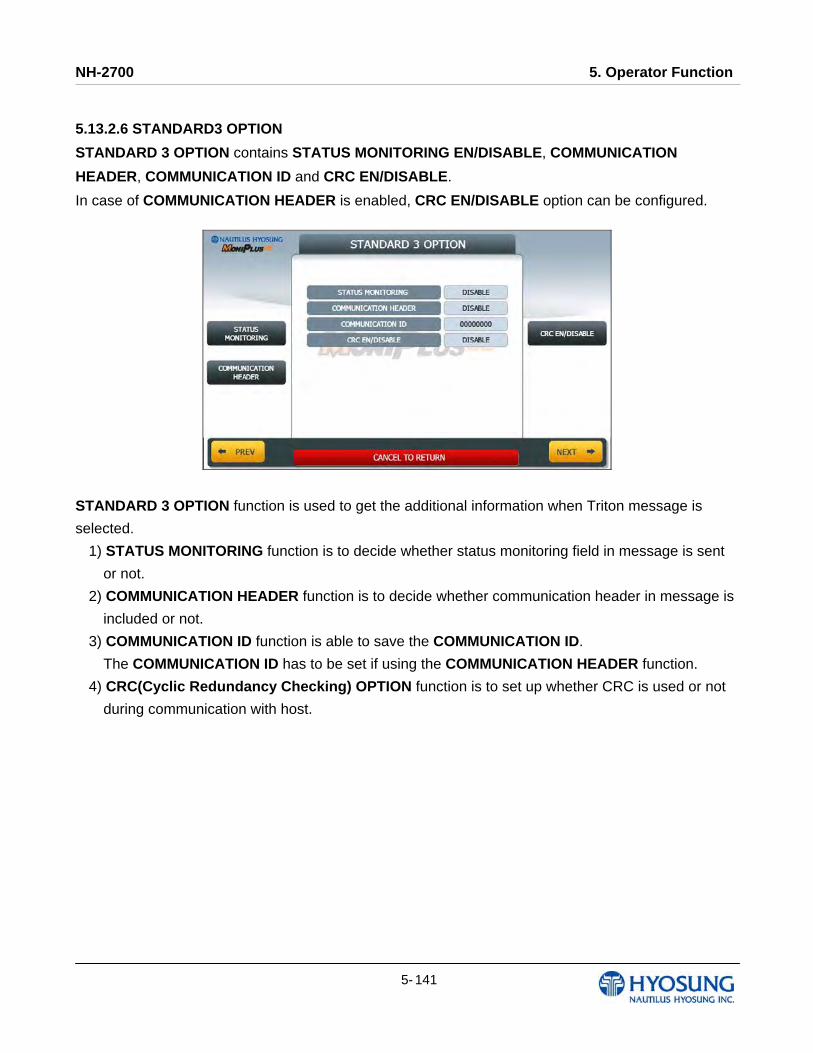
NH-2700 5. Operator Function
5- 141
5.13.2.6 STANDARD3 OPTION
STANDARD 3 OPTION contains STATUS MONITORING EN/DISABLE, COMMUNICATION
HEADER, COMMUNICATION ID and CRC EN/DISABLE.
In case of COMMUNICATION HEADER is enabled, CRC EN/DISABLE option can be configured.
STANDARD 3 OPTION function is used to get the additional information when Triton message is
selected.
1) STATUS MONITORING function is to decide whether status monitoring field in message is sent
or not.
2) COMMUNICATION HEADER function is to decide whether communication header in message is
included or not.
3) COMMUNICATION ID function is able to save the COMMUNICATION ID.
The COMMUNICATION ID has to be set if using the COMMUNICATION HEADER function.
4) CRC(Cyclic Redundancy Checking) OPTION function is to set up whether CRC is used or not
during communication with host.
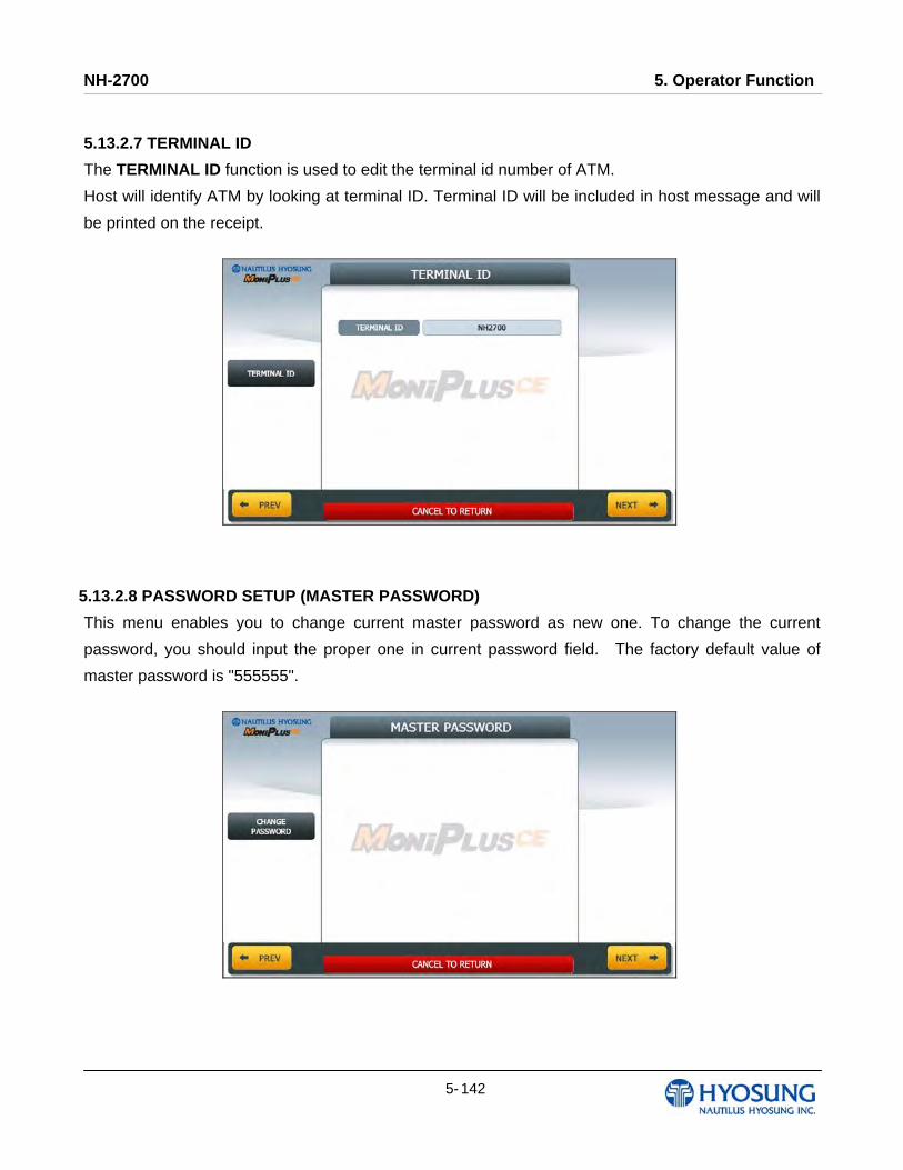
NH-2700 5. Operator Function
5- 142
5.13.2.7 TERMINAL ID
The TERMINAL ID function is used to edit the terminal id number of ATM.
Host will identify ATM by looking at terminal ID. Terminal ID will be included in host message and will
be printed on the receipt.
5.13.2.8 PASSWORD SETUP (MASTER PASSWORD)
This menu enables you to change current master password as new one. To change the current
password, you should input the proper one in current password field. The factory default value of
master password is "555555".
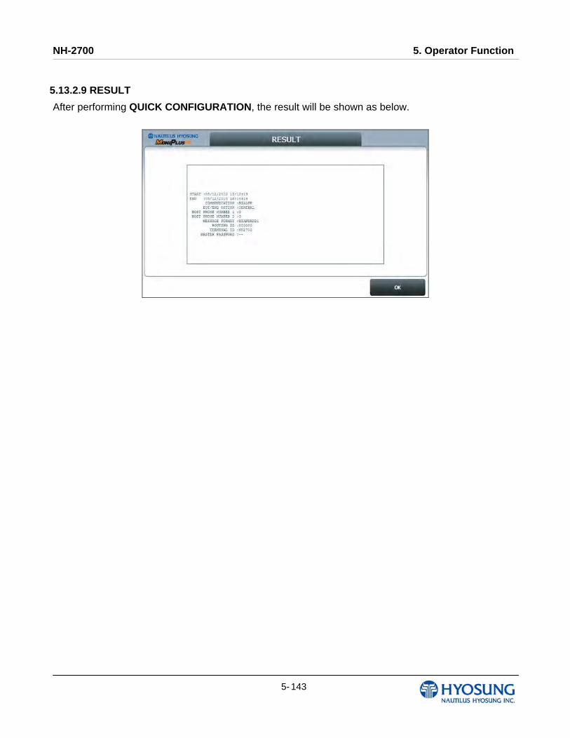
NH-2700 5. Operator Function
5- 143
5.13.2.9 RESULT
After performing QUICK CONFIGURATION, the result will be shown as below.
NH-2700 6. Installation
6- 1
Chapter 6. Installation
NH-2700 6. Installation
6- 2
6. Installation
6.1 Installation Information Installation condition and space
Following conditions should be met before installing equipment.
1) Temperature while operating should be between 41°F - 104°F.
2) Relative humidity while operating should be between 25% < RH < 85%, Non-Condensed.
3) Avoid locations where intense direct light is reflected off the LCD screen.
4) Avoid locations where strong static electricity can occur.
5) Avoid placing the product next to equipment that produces electromagnetic waves. It could interfere
with data transfer.
6) The floor must allow easy wheelchair access from the front or the side.
7) Space required for servicing the machine should be considered before installation.
Tools required for installation
In order to move the machine and place it in a proper location, you should seek the help of
professionals trained in moving heavy equipment.
Following tools are needed to install the machine.
1) Wire cutter
2) Lifter
3) Screw driver (Flat, Phillips)
4) Wrench (Spanner)
5) Leveling tool
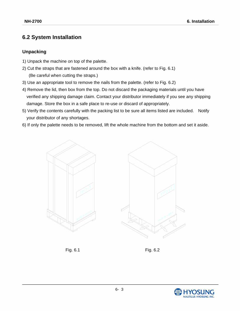
NH-2700 6. Installation
6- 3
6.2 System Installation
Unpacking
1) Unpack the machine on top of the palette.
2) Cut the straps that are fastened around the box with a knife. (refer to Fig. 6.1)
(Be careful when cutting the straps.)
3) Use an appropriate tool to remove the nails from the palette. (refer to Fig. 6.2)
4) Remove the lid, then box from the top. Do not discard the packaging materials until you have
verified any shipping damage claim. Contact your distributor immediately if you see any shipping
damage. Store the box in a safe place to re-use or discard of appropriately.
5) Verify the contents carefully with the packing list to be sure all items listed are included. Notify
your distributor of any shortages.
6) If only the palette needs to be removed, lift the whole machine from the bottom and set it aside.
Fig. 6.1 Fig. 6.2
NH-2700 6. Installation
6- 4
Physical Installation
To install NH-2700 ATM, perform the following steps.
1) Place the “Anchor bolts locate sheet” at the place where the machine is to be installed. (refer to
Fig. 6.3)
2) Place the system on a flat surface. Be careful when opening the top or bottom of the machine
because it can be off balance
3) Place the Anchor nuts into the ground according to the anchor bolts locate sheet.
(4 places)
4) Place NH-2700 ATM on top of the sheet.
5) Open the Security cover with the key provided.
6) Using the supplied combination (factory preset at 50-25-50 for dial lock & cencon lock and 1-2-3-4-
5-6 for electronic lock) open the Security Door.
This combination should be changed as soon as possible. Refer to Chapter 4 for instructions on
changing the lock combination.
7) After the anchor nuts are in place according to the anchor holes on the bottom of NH-2700 ATM,
tighten the anchor bolts tightly.
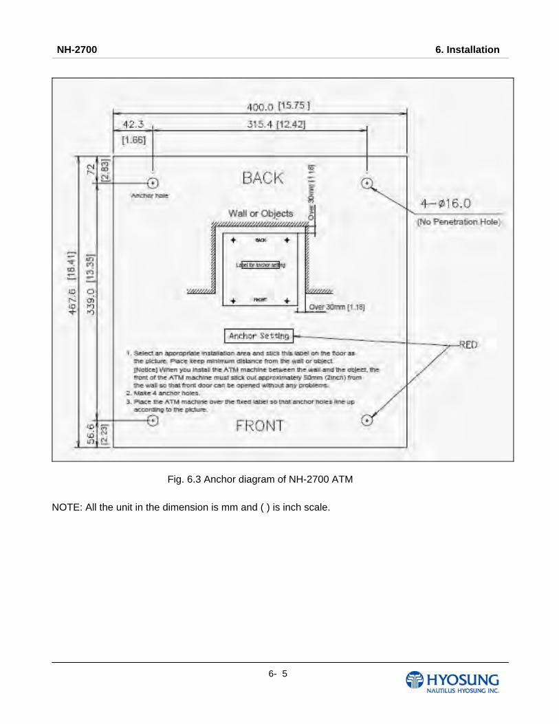
NH-2700 6. Installation
6- 5
Fig. 6.3 Anchor diagram of NH-2700 ATM
NOTE: All the unit in the dimension is mm and ( ) is inch scale.
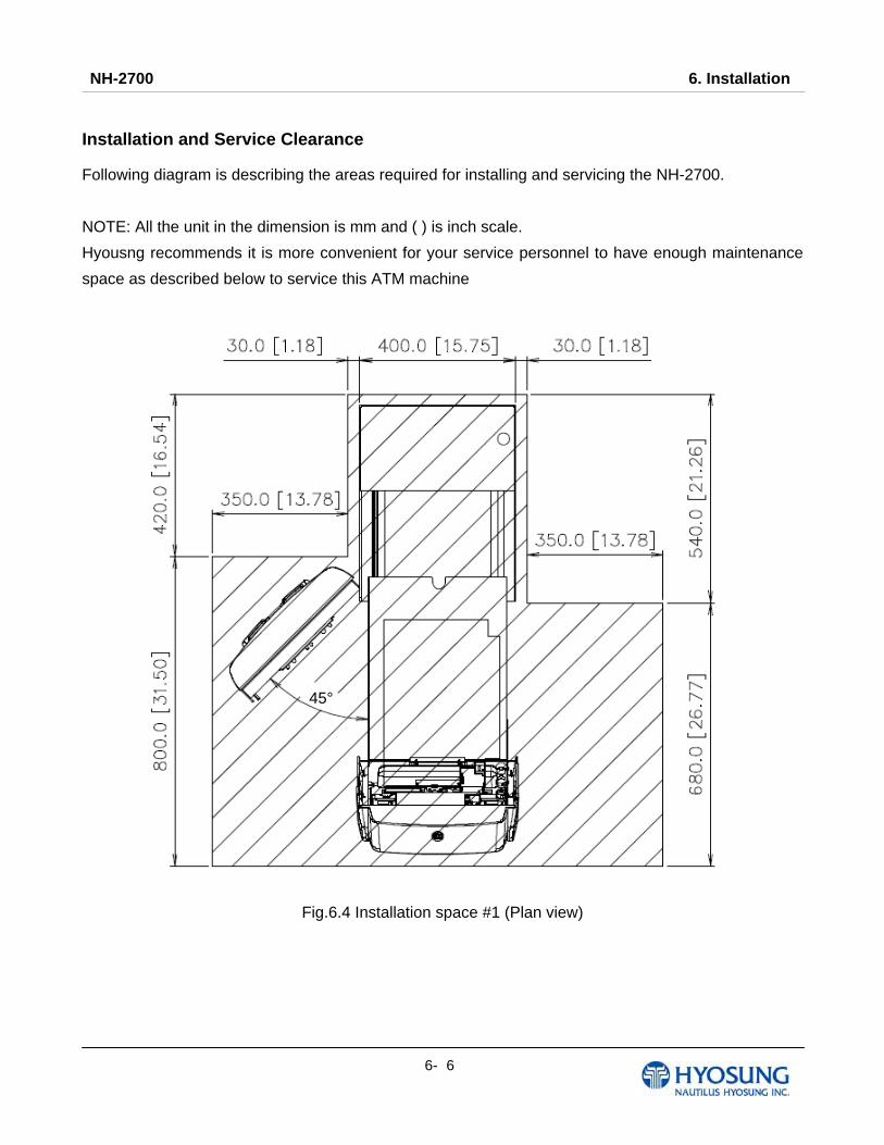
NH-2700 6. Installation
6- 6
Installation and Service Clearance
Following diagram is describing the areas required for installing and servicing the NH-2700.
NOTE: All the unit in the dimension is mm and ( ) is inch scale.
Hyousng recommends it is more convenient for your service personnel to have enough maintenance
space as described below to service this ATM machine
Fig.6.4 Installation space #1 (Plan view)
45°
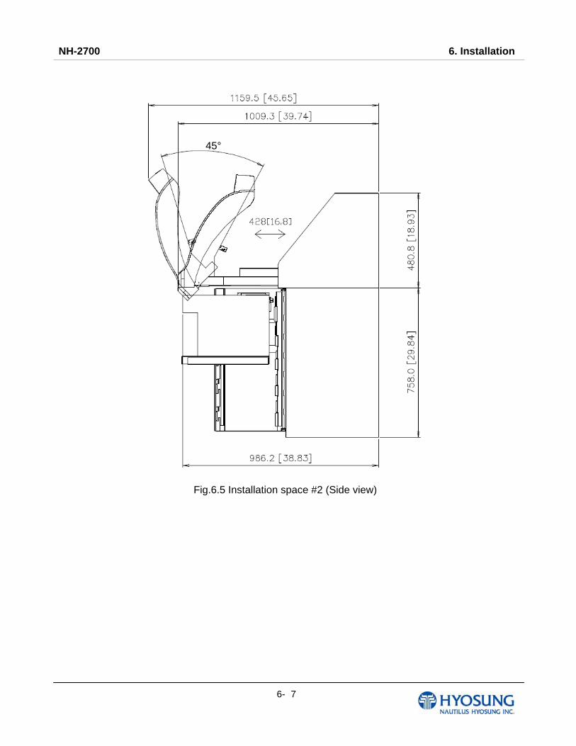
NH-2700 6. Installation
6- 7
Fig.6.5 Installation space #2 (Side view)
45°
NH-2700 6. Installation
6- 8
6.3 Hardware Installation 1) Verify the power voltage (110/220V) to be used and set the appropriate voltage on the power
supply.
2) Verify that the telephone line to be used for the ATM is in proper working order. Hyosung
recommends the use of shielded phone line in locations with close proximity to other appliances.
(For Dial-up)
3) Open the security door and remove any shipping materials and note any warning or installation
instructions.
4) Remove the screw, which is set to hold the Cash Dispensing Unit platform in place.
5) Remove the cash cassette from the box, fill the cassette with the appropriate amount of notes, and
place it in the Cash Dispensing Unit carefully. Place the appropriate denomination label on the
front of the cassette.
6) Before closing the vault, thoroughly test the combination lock by locking and unlocking the lock
several times. It is much easier to diagnose potential lock problems before shutting the door
7) Open the top of the ATM. Place the receipt paper in the Receipt Printer. The paper prints only on
one side (shiny side) always check the roll when you install paper.
Place the roll so that the coated side (shiny side) will be facing up.
8) Connect the Power cable and telephone cable to the appropriate outlets on the wall.
(Verify once again if the power voltage is 110V or 220V)
9) Turn the power on and verify if all systems are operational. If any part of the system is not
operational then an error code will be displayed. Verify with the Error Code and follow the
appropriate steps. If the error is not corrected please contact your local distributor. Set all the
system parameters.

NH-2700 7. Appendix
7- 1
Chapter 7. Appendix
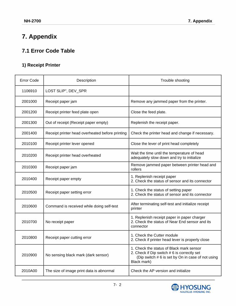
NH-2700 7. Appendix
7- 2
7. Appendix 7.1 Error Code Table
1) Receipt Printer
Error Code Description Trouble shooting
1106910 LOST SLIP", DEV_SPR
2001000 Receipt paper jam Remove any jammed paper from the printer.
2001200 Receipt printer feed plate open Close the feed plate.
2001300 Out of receipt (Receipt paper empty) Replenish the receipt paper.
2001400 Receipt printer head overheated before printing Check the printer head and change if necessary.
2010100 Receipt printer lever opened Close the lever of print head completely
2010200 Receipt printer head overheated Wait the time until the temperature of head adequately slow down and try to initialize
2010300 Receipt paper jam Remove jammed paper between printer head and rollers
2010400 Receipt paper empty 1. Replenish receipt paper 2. Check the status of sensor and its connector
2010500 Receipt paper setting error 1. Check the status of setting paper 2. Check the status of sensor and its connector
2010600 Command is received while doing self-test After terminating self-test and initialize receipt printer
2010700 No receipt paper 1. Replenish receipt paper in paper charger 2. Check the status of Near End sensor and its connector
2010800 Receipt paper cutting error 1. Check the Cutter module 2. Check if printer head lever is properly close
2010900 No sensing black mark (dark sensor)
1. Check the status of Black mark sensor 2. Check if Dip switch # 6 is correctly set (Dip switch # 6 is set by On in case of not using Black mark)
2010A00 The size of image print data is abnormal Check the AP version and initialize

NH-2700 7. Appendix
7- 3
Error Code Description Trouble shooting
2080100 Receipt printer lever opened Close the lever of print head completely
2080200 Receipt printer head overheated Wait the time until the temperature of head adequately slow down and try to initialize
2080300 Receipt paper jam Remove jammed paper between printer head and rollers
2080400 Receipt paper empty 1. Replenish receipt paper 2. Check the status of sensor and its connector
2080500 Receipt paper setting error 1. Check the status of setting paper 2. Check the status of sensor and its connector
2080600 Command is received while doing self-test After terminating self-test and initialize receipt printer
2080700 No receipt paper 1. Replenish receipt paper in paper charger 2. Check the status of Near End sensor and its connector
2080800 Receipt paper cutting error 1. Check the Cutter module 2. Check if printer head lever is properly close
2080900 No sensing black mark (dark sensor)
1. Check the status of Black mark sensor 2. Check if Dip switch # 6 is correctly set (Dip switch # 6 is set by On in case of not using Black mark)
2080A00 The size of image print data is abnormal Check the AP version and initialize
2080B00 Margin setting error 1. Check whether the default registry setting is
changed 2. Reset the PTR SP
2080C00 Paper jammed at the exit of the slot 1. Remove the jammed paper
2080D00 Paper jammed in the path 1. Remove the jammed paper
2080F00 The firmware crashed 1. Check whether the dip switch #1 is set to “ON”
position 2. Update the firmware
2DN0000 Failed to connect communication between Receipt printer and SP
1.Check if communication cable or com port is not connected
9720000 Receipt printer communication error during SP opening
Check if communication cable or COM port is not connected
9722010 Receipt Printer communication failure during COM port open
1. Do RESET at Operator Function 2. Reboot ATM
9722DN0 Receipt Printer communication failure during sending command to Receipt Printer
1. Do RESET at Operator Function 2. Reboot ATM
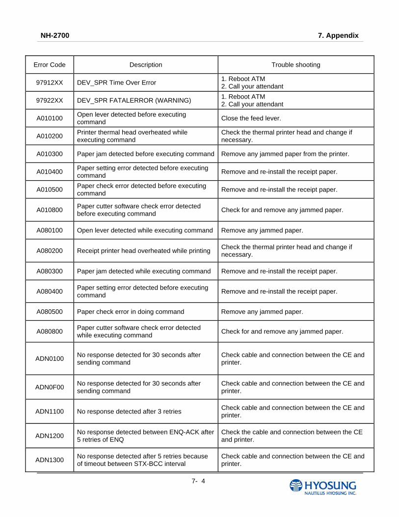
NH-2700 7. Appendix
7- 4
Error Code Description Trouble shooting
97912XX DEV_SPR Time Over Error 1. Reboot ATM 2. Call your attendant
97922XX DEV_SPR FATALERROR (WARNING) 1. Reboot ATM 2. Call your attendant
A010100 Open lever detected before executing command Close the feed lever.
A010200 Printer thermal head overheated while executing command
Check the thermal printer head and change if necessary.
A010300 Paper jam detected before executing command Remove any jammed paper from the printer.
A010400 Paper setting error detected before executing command Remove and re-install the receipt paper.
A010500 Paper check error detected before executing command Remove and re-install the receipt paper.
A010800 Paper cutter software check error detected before executing command Check for and remove any jammed paper.
A080100 Open lever detected while executing command Remove any jammed paper.
A080200 Receipt printer head overheated while printing Check the thermal printer head and change if necessary.
A080300 Paper jam detected while executing command Remove and re-install the receipt paper.
A080400 Paper setting error detected before executing command Remove and re-install the receipt paper.
A080500 Paper check error in doing command Remove any jammed paper.
A080800 Paper cutter software check error detected while executing command Check for and remove any jammed paper.
ADN0100 No response detected for 30 seconds after sending command
Check cable and connection between the CE and printer.
ADN0F00 No response detected for 30 seconds after sending command
Check cable and connection between the CE and printer.
ADN1100 No response detected after 3 retries Check cable and connection between the CE and printer.
ADN1200 No response detected between ENQ-ACK after 5 retries of ENQ
Check the cable and connection between the CE and printer.
ADN1300 No response detected after 5 retries because of timeout between STX-BCC interval
Check cable and connection between the CE and printer.
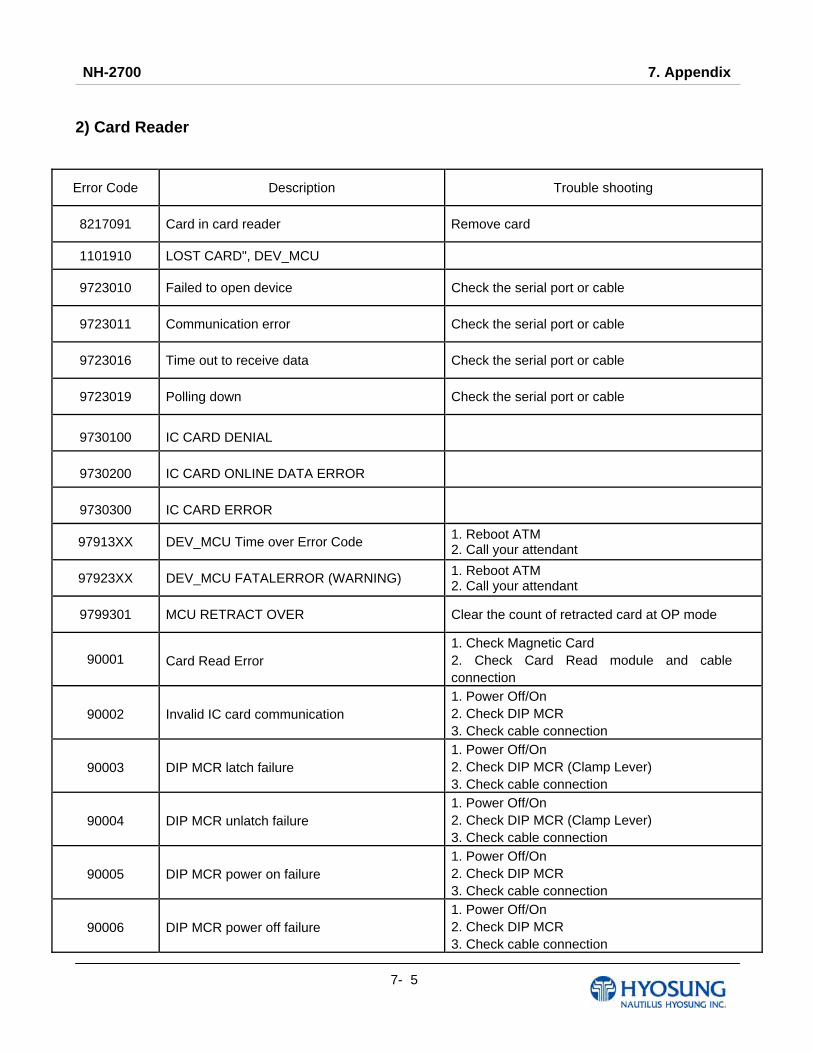
NH-2700 7. Appendix
7- 5
2) Card Reader
Error Code Description Trouble shooting
8217091 Card in card reader Remove card
1101910 LOST CARD", DEV_MCU
9723010 Failed to open device Check the serial port or cable
9723011 Communication error Check the serial port or cable
9723016 Time out to receive data Check the serial port or cable
9723019 Polling down Check the serial port or cable
9730100 IC CARD DENIAL
9730200 IC CARD ONLINE DATA ERROR
9730300 IC CARD ERROR
97913XX DEV_MCU Time over Error Code 1. Reboot ATM 2. Call your attendant
97923XX DEV_MCU FATALERROR (WARNING) 1. Reboot ATM 2. Call your attendant
9799301 MCU RETRACT OVER Clear the count of retracted card at OP mode
90001 Card Read Error 1. Check Magnetic Card 2. Check Card Read module and cable connection
90002 Invalid IC card communication 1. Power Off/On 2. Check DIP MCR 3. Check cable connection
90003 DIP MCR latch failure 1. Power Off/On 2. Check DIP MCR (Clamp Lever) 3. Check cable connection
90004 DIP MCR unlatch failure 1. Power Off/On 2. Check DIP MCR (Clamp Lever) 3. Check cable connection
90005 DIP MCR power on failure 1. Power Off/On 2. Check DIP MCR 3. Check cable connection
90006 DIP MCR power off failure 1. Power Off/On 2. Check DIP MCR 3. Check cable connection
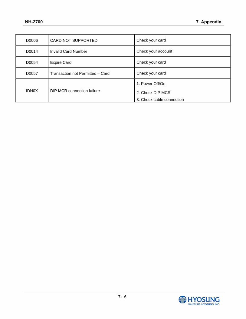
NH-2700 7. Appendix
7- 6
D0006 CARD NOT SUPPORTED Check your card
D0014 Invalid Card Number Check your account
D0054 Expire Card Check your card
D0057 Transaction not Permitted – Card Check your card
IDN0X DIP MCR connection failure
1. Power Off/On
2. Check DIP MCR
3. Check cable connection
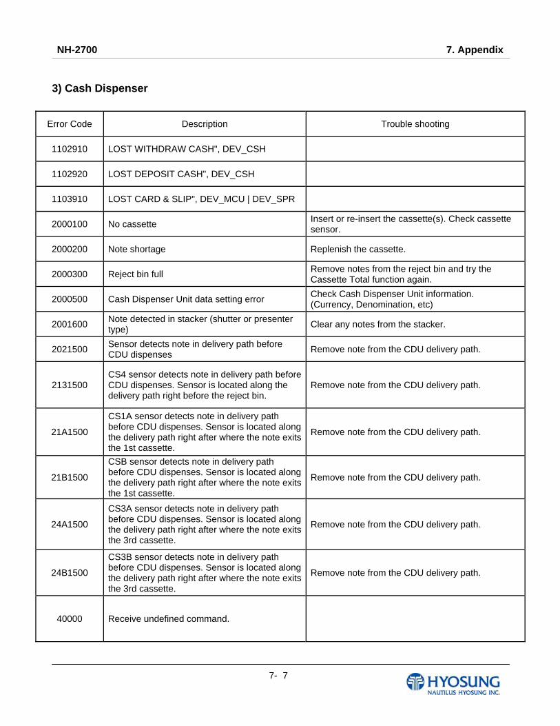
NH-2700 7. Appendix
7- 7
3) Cash Dispenser
Error Code Description Trouble shooting
1102910 LOST WITHDRAW CASH", DEV_CSH
1102920 LOST DEPOSIT CASH", DEV_CSH
1103910 LOST CARD & SLIP", DEV_MCU | DEV_SPR
2000100 No cassette Insert or re-insert the cassette(s). Check cassette sensor.
2000200 Note shortage Replenish the cassette.
2000300 Reject bin full Remove notes from the reject bin and try the Cassette Total function again.
2000500 Cash Dispenser Unit data setting error Check Cash Dispenser Unit information. (Currency, Denomination, etc)
2001600 Note detected in stacker (shutter or presenter type) Clear any notes from the stacker.
2021500 Sensor detects note in delivery path before CDU dispenses Remove note from the CDU delivery path.
2131500 CS4 sensor detects note in delivery path before CDU dispenses. Sensor is located along the delivery path right before the reject bin.
Remove note from the CDU delivery path.
21A1500
CS1A sensor detects note in delivery path before CDU dispenses. Sensor is located along the delivery path right after where the note exits the 1st cassette.
Remove note from the CDU delivery path.
21B1500
CSB sensor detects note in delivery path before CDU dispenses. Sensor is located along the delivery path right after where the note exits the 1st cassette.
Remove note from the CDU delivery path.
24A1500
CS3A sensor detects note in delivery path before CDU dispenses. Sensor is located along the delivery path right after where the note exits the 3rd cassette.
Remove note from the CDU delivery path.
24B1500
CS3B sensor detects note in delivery path before CDU dispenses. Sensor is located along the delivery path right after where the note exits the 3rd cassette.
Remove note from the CDU delivery path.
40000 Receive undefined command.
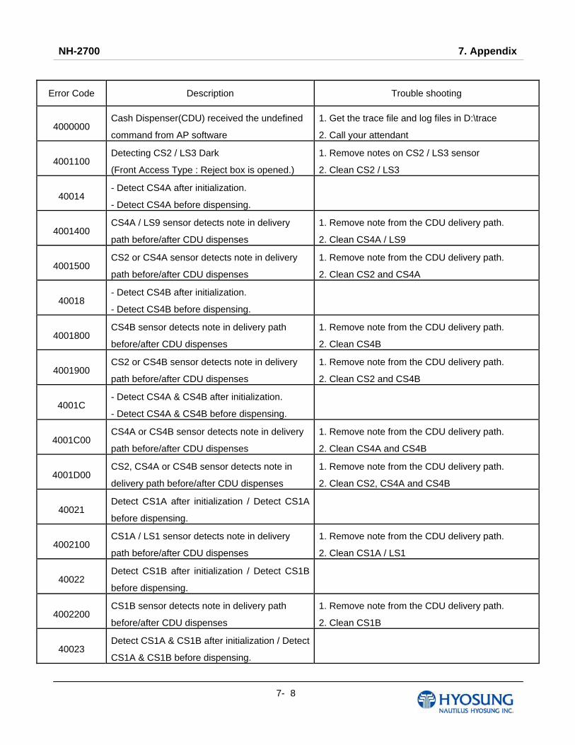
NH-2700 7. Appendix
7- 8
Error Code Description Trouble shooting
4000000 Cash Dispenser(CDU) received the undefined
command from AP software
1. Get the trace file and log files in D:\trace
2. Call your attendant
4001100 Detecting CS2 / LS3 Dark
(Front Access Type : Reject box is opened.)
1. Remove notes on CS2 / LS3 sensor
2. Clean CS2 / LS3
40014 - Detect CS4A after initialization.
- Detect CS4A before dispensing.
4001400 CS4A / LS9 sensor detects note in delivery
path before/after CDU dispenses
1. Remove note from the CDU delivery path.
2. Clean CS4A / LS9
4001500 CS2 or CS4A sensor detects note in delivery
path before/after CDU dispenses
1. Remove note from the CDU delivery path.
2. Clean CS2 and CS4A
40018 - Detect CS4B after initialization.
- Detect CS4B before dispensing.
4001800 CS4B sensor detects note in delivery path
before/after CDU dispenses
1. Remove note from the CDU delivery path.
2. Clean CS4B
4001900 CS2 or CS4B sensor detects note in delivery
path before/after CDU dispenses
1. Remove note from the CDU delivery path.
2. Clean CS2 and CS4B
4001C - Detect CS4A & CS4B after initialization.
- Detect CS4A & CS4B before dispensing.
4001C00 CS4A or CS4B sensor detects note in delivery
path before/after CDU dispenses
1. Remove note from the CDU delivery path.
2. Clean CS4A and CS4B
4001D00 CS2, CS4A or CS4B sensor detects note in
delivery path before/after CDU dispenses
1. Remove note from the CDU delivery path.
2. Clean CS2, CS4A and CS4B
40021 Detect CS1A after initialization / Detect CS1A
before dispensing.
4002100 CS1A / LS1 sensor detects note in delivery
path before/after CDU dispenses
1. Remove note from the CDU delivery path.
2. Clean CS1A / LS1
40022 Detect CS1B after initialization / Detect CS1B
before dispensing.
4002200 CS1B sensor detects note in delivery path
before/after CDU dispenses
1. Remove note from the CDU delivery path.
2. Clean CS1B
40023 Detect CS1A & CS1B after initialization / Detect
CS1A & CS1B before dispensing.
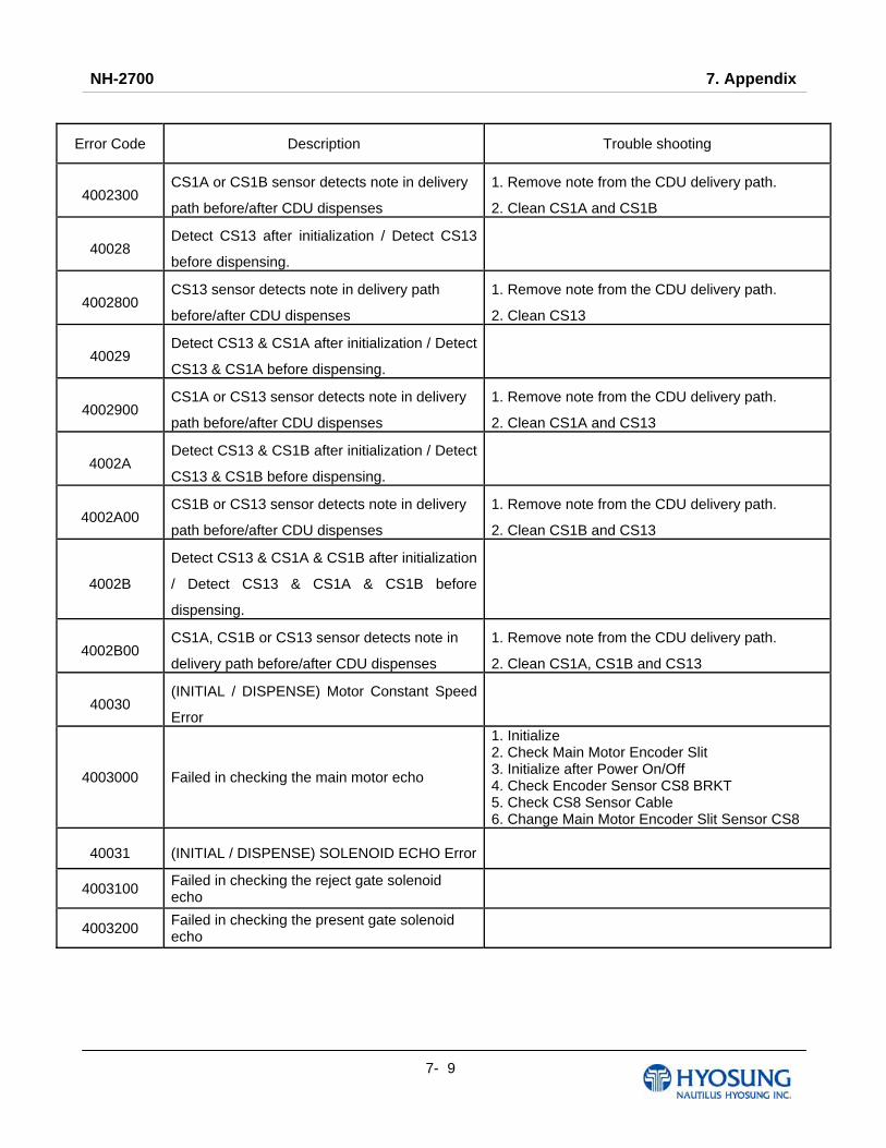
NH-2700 7. Appendix
7- 9
Error Code Description Trouble shooting
4002300 CS1A or CS1B sensor detects note in delivery
path before/after CDU dispenses
1. Remove note from the CDU delivery path.
2. Clean CS1A and CS1B
40028 Detect CS13 after initialization / Detect CS13
before dispensing.
4002800 CS13 sensor detects note in delivery path
before/after CDU dispenses
1. Remove note from the CDU delivery path.
2. Clean CS13
40029 Detect CS13 & CS1A after initialization / Detect
CS13 & CS1A before dispensing.
4002900 CS1A or CS13 sensor detects note in delivery
path before/after CDU dispenses
1. Remove note from the CDU delivery path.
2. Clean CS1A and CS13
4002A Detect CS13 & CS1B after initialization / Detect
CS13 & CS1B before dispensing.
4002A00 CS1B or CS13 sensor detects note in delivery
path before/after CDU dispenses
1. Remove note from the CDU delivery path.
2. Clean CS1B and CS13
4002B
Detect CS13 & CS1A & CS1B after initialization
/ Detect CS13 & CS1A & CS1B before
dispensing.
4002B00 CS1A, CS1B or CS13 sensor detects note in
delivery path before/after CDU dispenses
1. Remove note from the CDU delivery path.
2. Clean CS1A, CS1B and CS13
40030 (INITIAL / DISPENSE) Motor Constant Speed
Error
4003000 Failed in checking the main motor echo
1. Initialize 2. Check Main Motor Encoder Slit 3. Initialize after Power On/Off 4. Check Encoder Sensor CS8 BRKT 5. Check CS8 Sensor Cable 6. Change Main Motor Encoder Slit Sensor CS8
40031 (INITIAL / DISPENSE) SOLENOID ECHO Error
4003100 Failed in checking the reject gate solenoid echo
4003200 Failed in checking the present gate solenoid echo

NH-2700 7. Appendix
7- 10
Error Code Description Trouble shooting
4003300 Check sum error (No information is set)
1. Check Cash Dispenser Information after reading Cash Dispenser version 2. Initialize 3. Initialize after executing Cash Dispenser Information Set(‘P’) Command 4. Change Cash Dispenser B/D
4003400 Error of two sheets detecting sensor(CS5_1) for initializing
1. Check CS5_1 Sensor Cable 2. Check second Dip Switch in Cash Dispenser B/D3. Change CS5_1 Sensor
40036 Detect CS13 before initialization.
4003600 Error of CS 2, CS13 / LS2 sensor during initialization
1.Remove a jammed note in CS13 / LS2 sensor. 2.Replace CS13 / LS2 sensor.
4003700 Error of 2 sheets detecting sensor (CS5_1 / CS5_2) for dispensing
1. Check Cash Dispenser Board Segment 2. Initialize 3. Read data of ‘Read Double Sensor’ Command
4003800 Error in checking SRAM
40039 (INITIAL / DISPENSE) Solenoid Operation
Error before motor activation
4003900 Gate operation sensor (CS3 / LS8) error before initial recovery
1. Initialize after removing notes or dust over Gate 2. Check CS3 / LS8 Sensor BKRT 3. Check CS3 / LS8 Sensor Cable 4. Exchange Sensor after abnormal operating
CS3 / LS8 Gate detecting Sensor 5. Replace Reject Solenoid 1
4003A00 When more than 5 sheets of cash dispensing is required during a test
1. Check command that Cash Dispenser is received 2. Check Cash Dispenser EP ROM Version or specification
4003B00 When CS15A or CS 15B sensor is detected as dark after initial recovery
1. Remove notes or dust on CS15A Sensor 2. Check CS15A Sensor Cable 3. Exchange Sensor after abnormal operating CS15A Sensor
40040 (DISPENSE) Reboot 5 or more times due to
cassette separation
4004000 Cassette is removed during dispensing 1. Check the cassette catcher 2. Set the cassette properly
40041 (DISPENSE) Reboot 12 or more times
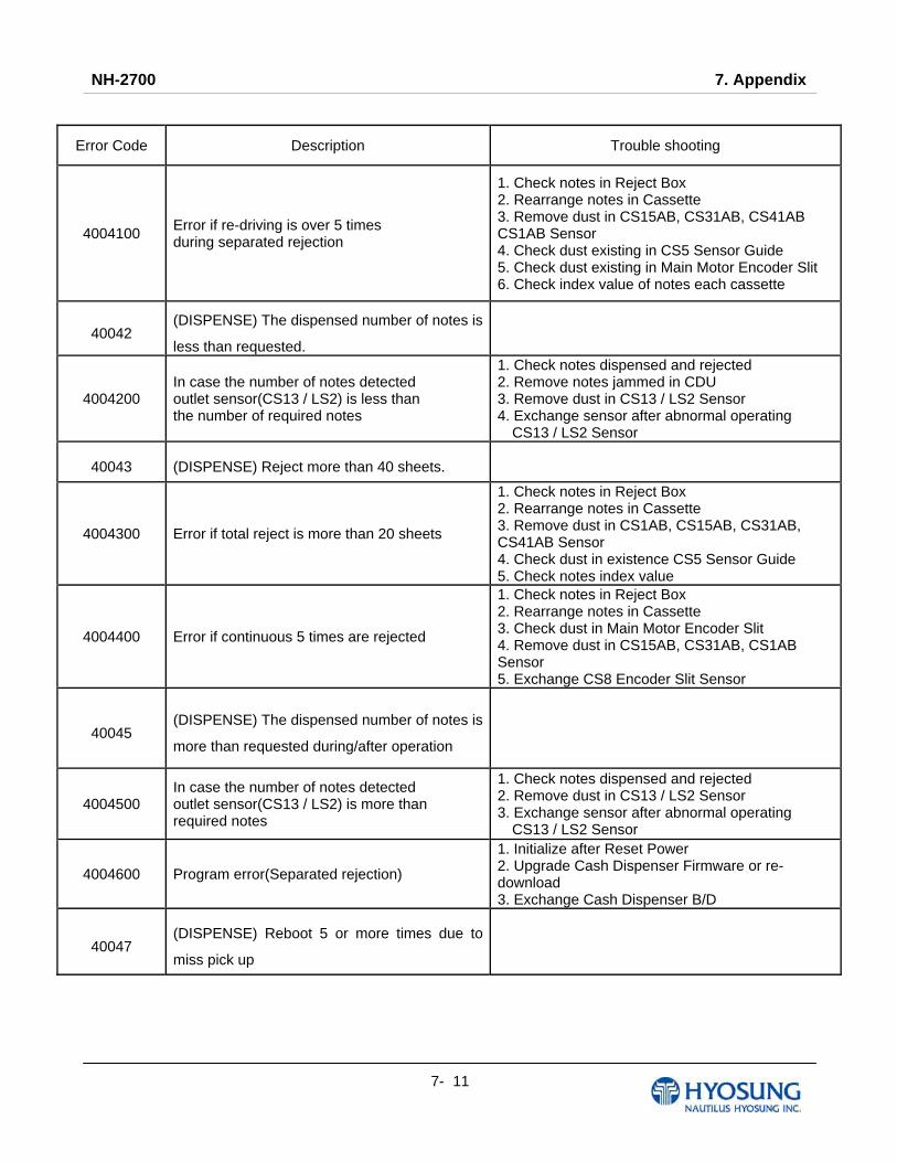
NH-2700 7. Appendix
7- 11
Error Code Description Trouble shooting
4004100 Error if re-driving is over 5 times during separated rejection
1. Check notes in Reject Box 2. Rearrange notes in Cassette 3. Remove dust in CS15AB, CS31AB, CS41AB CS1AB Sensor 4. Check dust existing in CS5 Sensor Guide 5. Check dust existing in Main Motor Encoder Slit 6. Check index value of notes each cassette
40042 (DISPENSE) The dispensed number of notes is
less than requested.
4004200 In case the number of notes detected outlet sensor(CS13 / LS2) is less than the number of required notes
1. Check notes dispensed and rejected 2. Remove notes jammed in CDU 3. Remove dust in CS13 / LS2 Sensor 4. Exchange sensor after abnormal operating
CS13 / LS2 Sensor
40043 (DISPENSE) Reject more than 40 sheets.
4004300 Error if total reject is more than 20 sheets
1. Check notes in Reject Box 2. Rearrange notes in Cassette 3. Remove dust in CS1AB, CS15AB, CS31AB, CS41AB Sensor 4. Check dust in existence CS5 Sensor Guide 5. Check notes index value
4004400 Error if continuous 5 times are rejected
1. Check notes in Reject Box 2. Rearrange notes in Cassette 3. Check dust in Main Motor Encoder Slit 4. Remove dust in CS15AB, CS31AB, CS1AB Sensor 5. Exchange CS8 Encoder Slit Sensor
40045 (DISPENSE) The dispensed number of notes is
more than requested during/after operation
4004500 In case the number of notes detected outlet sensor(CS13 / LS2) is more than required notes
1. Check notes dispensed and rejected 2. Remove dust in CS13 / LS2 Sensor 3. Exchange sensor after abnormal operating CS13 / LS2 Sensor
4004600 Program error(Separated rejection)
1. Initialize after Reset Power 2. Upgrade Cash Dispenser Firmware or re-download 3. Exchange Cash Dispenser B/D
40047 (DISPENSE) Reboot 5 or more times due to
miss pick up
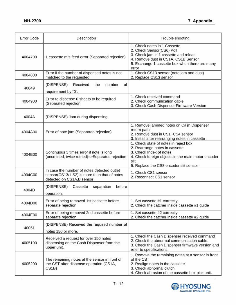
NH-2700 7. Appendix
7- 12
Error Code Description Trouble shooting
4004700 1 cassette mis-feed error (Separated rejection)
1. Check notes in 1 Cassette 2. Check Sensor(CS6) Poll 3. Check jam in 1 cassette and reload 4. Remove dust in CS1A, CS1B Sensor 5. Exchange 1 cassette box when there are many error
4004800 Error if the number of dispensed notes is not matched to the requested
1. Check CS13 sensor (note jam and dust) 2. Replace CS13 sensor
40049 (DISPENSE) Received the number of
requirement by “0”.
4004900 Error to dispense 0 sheets to be required (Separated rejection
1. Check received command 2. Check communication cable 3. Check Cash Dispenser Firmware Version
4004A (DISPENSE) Jam during dispensing.
4004A00 Error of note jam (Separated rejection)
1. Remove jammed notes on Cash Dispenser return path 2. Remove dust in CS1~CS4 sensor 3. Install after rearranging notes in cassette
4004B00 Continuous 3 times error if note is long (once tried, twice retried)=>Separated rejection
1. Check state of notes in reject box 2. Rearrange notes in cassette 3. Check Index of notes 4. Check foreign objects in the main motor encoder slit 5. Replace the CS8 encoder slit sensor
4004C00 In case the number of notes detected outlet sensor(CS13/ LS2) is more than that of notes detected on CS1A,B sensor
1. Check CS1 sensor 2. Reconnect CS1 sensor
4004D (DISPENSE) Cassette separation before
operation.
4004D00 Error of being removed 1st cassette before separate rejection
1. Set cassette #1 correctly 2. Check the catcher inside cassette #1 guide
4004E00 Error of being removed 2nd cassette before separate rejection
1. Set cassette #2 correctly 2. Check the catcher inside cassette #2 guide
40051 (DISPENSE) Received the required number of
notes 150 or more.
4005100 Received a request for over 150 notes dispensing on the Cash Dispenser from the upper unit.
1. Check the Cash Dispenser received command 2. Check the abnormal communication cable. 3. Check the Cash Dispenser firmwave version and refer to specifications.
4005200 The remaining notes at the sensor in front of the CST after dispense operation (CS1A, CS1B)
1. Remove the remaining notes at a sensor in front of the CST 2. Realign notes in the cassette 3. Check abnormal clutch. 4. Check abrasion of the cassette box pick unit.
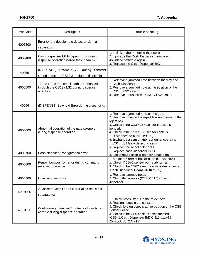
NH-2700 7. Appendix
7- 13
Error Code Description Trouble shooting
4005300 Error for the double note detection during
separation.
4005400 Cash Dispenser EP Program Error during dispense operation (failed table search)
1. Initialize after resetting the power 2. Upgrade the Cash Dispenser firmware or download software again 3. Replace the Cash Dispenser B/D
40055 (DISPENSE) Detect CS13 during constant
speed of motor / CS13 Jam during dispensing.
4005500 Timeout due to note’s length error passed through the CS13 / LS2 during dispense operation
1. Remove a jammed note between the tray and Cash Dispenser
2. Remove a jammed note at the position of the CS13 / LS2 sensor
3. Remove a dust on the CS13 / LS2 sensor
40056 (DISPENSE) Solenoid Error during dispensing.
4005600 Abnormal operation of the gate solenoid during dispense operation.
1. Remove a jammed note on the gate 2. Remove notes in the reject box and remount the reject box 3. Check if the CS3 / LS8 sensor bracket is bended. 4. Check if the CS3 / LS8 sensor cable is Disconnected (CN10 #9~10)
5. Exchange a sensor after abnormal operating CS3 / LS8 Gate detecting sensor. 6. Replace the reject solenoid 1
4005700 Cash dispenser configuration error 1. Replace cash dispenser PCB 2. Reconfigure cash dispenser setup data
4005800 Retract box position error during command reserved operation
1. Mount the retract box or open the box cover 2. Check if CS62 sensor poll is abnormal 3. Check if the CS62 sensor cable is disconnected (Cash Dispenser Board CN10 #5~2).
4005900 Initial jam time error 1. Remove jammed notes 2. Clean the sensors (CS1~CS15) in cash dispenser
4005B00 2 Cassette Miss Feed Error (Fail to reject bill
separately.)
4005D00 Continuously detected 2 notes for three times or more during dispense operation
1. Check notes’ status in the reject box 2. Realign notes in the cassette 3. Check foreign objects at the position of the CS5 Sensor Guide 4. Check if the CS5 cable is disconnected (CS5_1:Cash Dispenser B/D CN10 #11~12, 25~28/ CS5_2:CN12)
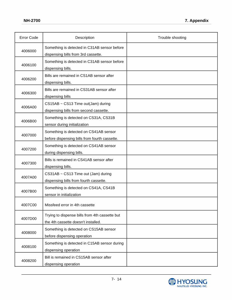
NH-2700 7. Appendix
7- 14
Error Code Description Trouble shooting
4006000 Something is detected in C31AB sensor before
dispensing bills from 3rd cassette.
4006100 Something is detected in C31AB sensor before
dispensing bills.
4006200 Bills are remained in CS1AB sensor after
dispensing bills.
4006300 Bills are remained in CS31AB sensor after
dispensing bills
4006A00 CS15AB ~ CS13 Time out(Jam) during
dispensing bills from second cassette.
4006B00 Something is detected on CS31A, CS31B
sensor during initialization
4007000 Something is detected on CS41AB sensor
before dispensing bills from fourth cassette.
4007200 Something is detected on CS41AB sensor
during dispensing bills.
4007300 Bills is remained in CS41AB sensor after
dispensing bills.
4007A00 CS31AB ~ CS13 Time out (Jam) during
dispensing bills from fourth cassette.
4007B00 Something is detected on CS41A, CS41B
sensor in initialization
4007C00 Missfeed error in 4th cassette
4007D00 Trying to dispense bills from 4th cassette but
the 4th cassette doesn't installed.
4008000 Something is detected on CS15AB sensor
before dispensing operation
4008100 Something is detected in C15AB sensor during
dispensing operation
4008200 Bill is remained in CS15AB sensor after
dispensing operation
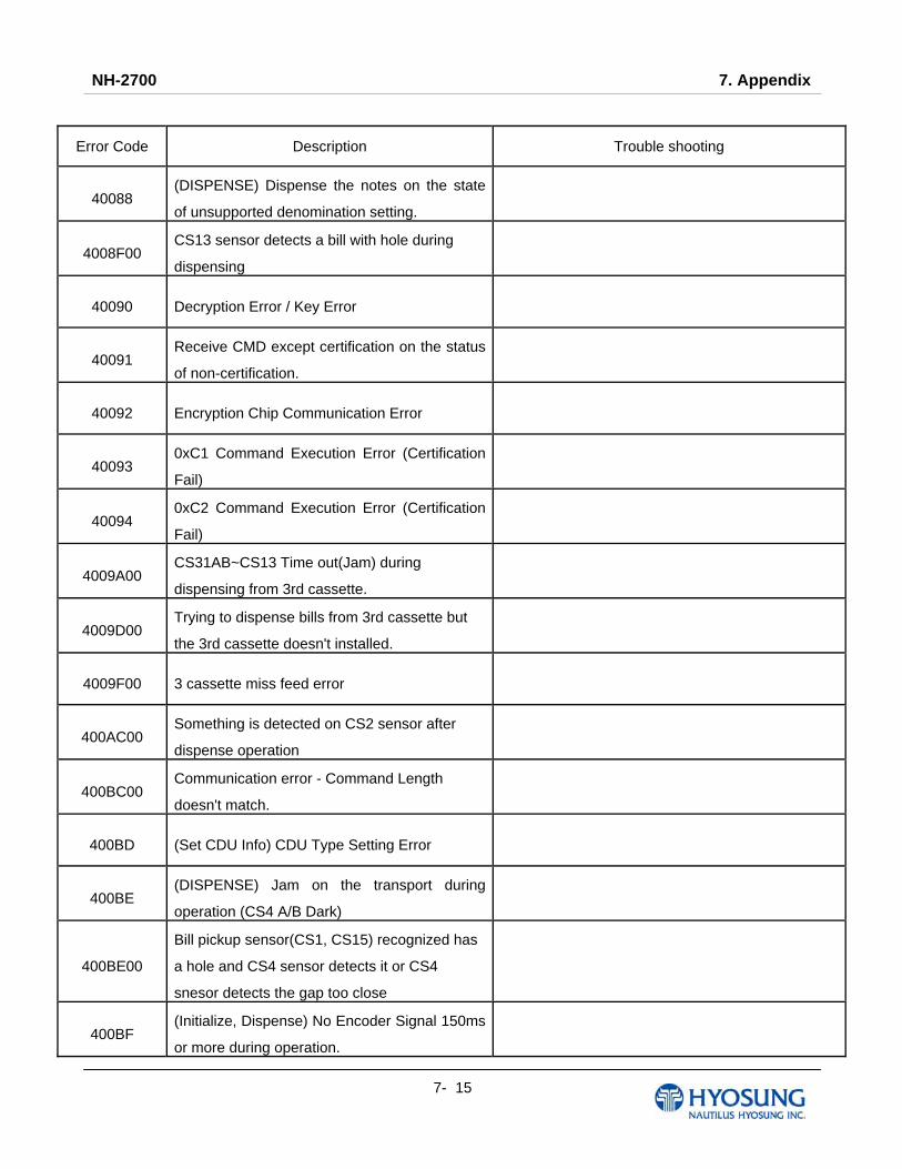
NH-2700 7. Appendix
7- 15
Error Code Description Trouble shooting
40088 (DISPENSE) Dispense the notes on the state
of unsupported denomination setting.
4008F00 CS13 sensor detects a bill with hole during
dispensing
40090 Decryption Error / Key Error
40091 Receive CMD except certification on the status
of non-certification.
40092 Encryption Chip Communication Error
40093 0xC1 Command Execution Error (Certification
Fail)
40094 0xC2 Command Execution Error (Certification
Fail)
4009A00 CS31AB~CS13 Time out(Jam) during
dispensing from 3rd cassette.
4009D00 Trying to dispense bills from 3rd cassette but
the 3rd cassette doesn't installed.
4009F00 3 cassette miss feed error
400AC00 Something is detected on CS2 sensor after
dispense operation
400BC00 Communication error - Command Length
doesn't match.
400BD (Set CDU Info) CDU Type Setting Error
400BE (DISPENSE) Jam on the transport during
operation (CS4 A/B Dark)
400BE00
Bill pickup sensor(CS1, CS15) recognized has
a hole and CS4 sensor detects it or CS4
snesor detects the gap too close
400BF (Initialize, Dispense) No Encoder Signal 150ms
or more during operation.
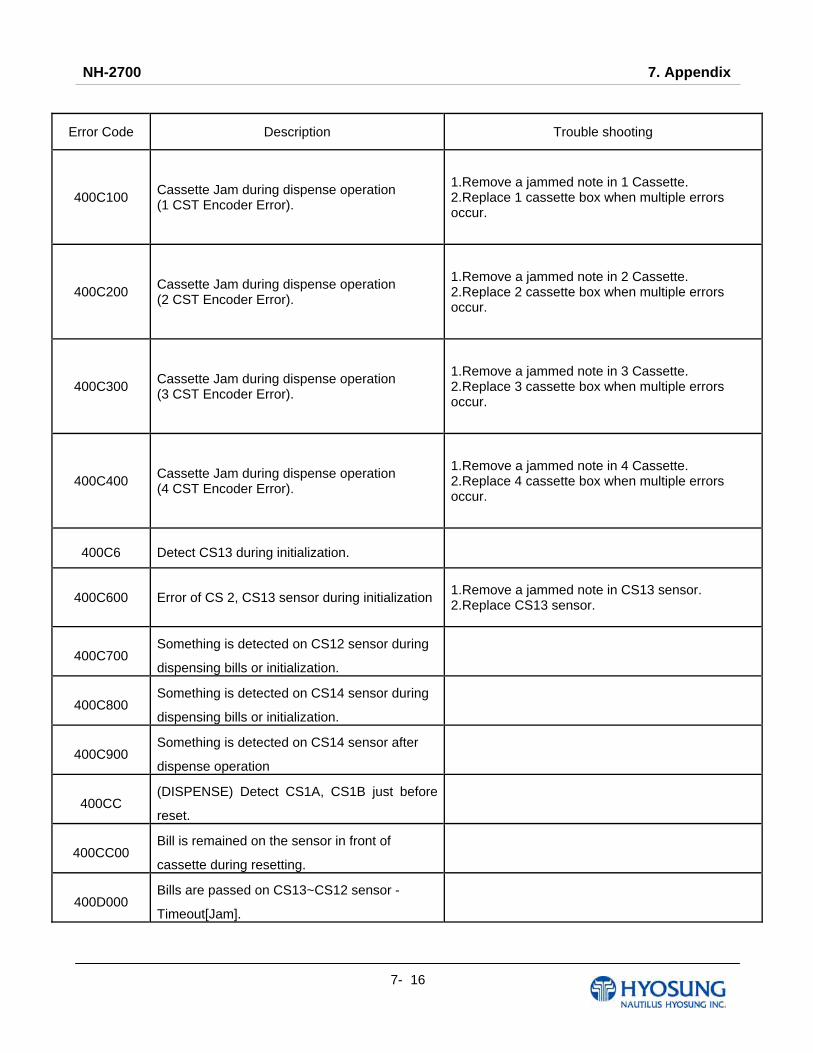
NH-2700 7. Appendix
7- 16
Error Code Description Trouble shooting
400C100 Cassette Jam during dispense operation (1 CST Encoder Error).
1.Remove a jammed note in 1 Cassette. 2.Replace 1 cassette box when multiple errors occur.
400C200 Cassette Jam during dispense operation (2 CST Encoder Error).
1.Remove a jammed note in 2 Cassette. 2.Replace 2 cassette box when multiple errors occur.
400C300 Cassette Jam during dispense operation (3 CST Encoder Error).
1.Remove a jammed note in 3 Cassette. 2.Replace 3 cassette box when multiple errors occur.
400C400 Cassette Jam during dispense operation (4 CST Encoder Error).
1.Remove a jammed note in 4 Cassette. 2.Replace 4 cassette box when multiple errors occur.
400C6 Detect CS13 during initialization.
400C600 Error of CS 2, CS13 sensor during initialization 1.Remove a jammed note in CS13 sensor. 2.Replace CS13 sensor.
400C700 Something is detected on CS12 sensor during
dispensing bills or initialization.
400C800 Something is detected on CS14 sensor during
dispensing bills or initialization.
400C900 Something is detected on CS14 sensor after
dispense operation
400CC (DISPENSE) Detect CS1A, CS1B just before
reset.
400CC00 Bill is remained on the sensor in front of
cassette during resetting.
400D000 Bills are passed on CS13~CS12 sensor -
Timeout[Jam].

NH-2700 7. Appendix
7- 17
Error Code Description Trouble shooting
400D100 Bills are passed on CS12~CS14 sensor -
Timeout[Jam].
400D7 DIP Switch Setting Error
400FF00 Bill jam 1. Remove the jammed notes 2. Initialize
4DN0000 Cash Dispenser communication failure during sending command to cash dispenser
1. Do RESET at Operator Function 2. Reboot ATM
4DN0100 Cash Dispenser communication failure during receiving command to cash dispenser
1. Do RESET at Operator Function 2. Reboot ATM
4DN8100 Communication error of Shutter
8216091 Cash jammed on Cash Dispenser 1. Remove jammed notes on Cash Dispenser return path 2. Remove dust in CS1~CS4 sensor
9712000 Failed to create file 1. Reboot ATM 2. Reinstall software 3. Replace hard disk drive
9712100 Failed to read file 1. Reboot ATM 2. Reinstall software 3. Replace hard disk drive
9712200 Failed to write file 1. Reboot ATM 2. Reinstall software 3. Replace hard disk drive
9712300 Failed to close file 1. Reboot ATM 2. Reinstall software 3. Replace hard disk drive
9712400 Failed to delete file 1. Reboot ATM 2. Reinstall software 3. Replace hard disk drive
9712500 Failed to copy file 1. Reboot ATM 2. Reinstall software 3. Replace hard disk drive
9712600 Failed to create directory 1. Reboot ATM 2. Reinstall software 3. Replace hard disk drive
9719000 Failed to execute an extra command in the status of Cash Unit Exchange
1. Reboot ATM 2. Reinstall software 3. Replace hard disk drive
9719100 In case of not being the status of Cash Unit Exchange out of End Exchange
1. Reboot ATM 2. Reinstall software 3. Replace hard disk drive
9719200 In case of carrying out Cash In Start command at two times
1. Reboot ATM 2. Reinstall software 3. Replace hard disk drive
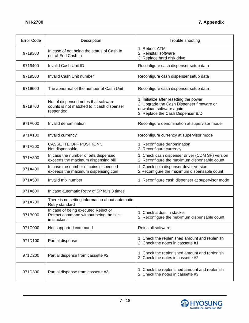
NH-2700 7. Appendix
7- 18
Error Code Description Trouble shooting
9719300 In case of not being the status of Cash In out of End Cash In
1. Reboot ATM 2. Reinstall software 3. Replace hard disk drive
9719400 Invalid Cash Unit ID Reconfigure cash dispenser setup data
9719500 Invalid Cash Unit number Reconfigure cash dispenser setup data
9719600 The abnormal of the number of Cash Unit Reconfigure cash dispenser setup data
9719700 No. of dispensed notes that software counts is not matched to it cash dispenser responded
1. Initialize after resetting the power 2. Upgrade the Cash Dispenser firmware or download software again 3. Replace the Cash Dispenser B/D
971A000 Invalid denomination Reconfigure denomination at supervisor mode
971A100 Invalid currency Reconfigure currency at supervisor mode
971A200 CASSETTE OFF POSITION”. Not dispensable
1. Reconfigure denomination 2. Reconfigure currency
971A300 In case the number of bills dispensed exceeds the maximum dispensing bill
1. Check cash dispenser driver (CDM SP) version 2. Reconfigure the maximum dispensable count
971A400 In case the number of coins dispensed exceeds the maximum dispensing coin
1. Check coin dispenser driver version 2.Reconfigure the maximum dispensable count
971A500 Invalid mix number 1. Reconfigure cash dispenser at supervisor mode
971A600 In case automatic Retry of SP fails 3 times
971A700 There is no setting information about automatic Retry standard
971B000 In case of being executed Reject or Retract command without being the bills in stacker.
1. Check a dust in stacker 2. Reconfigure the maximum dispensable count
971C000 Not supported command Reinstall software
971D100 Partial dispense 1. Check the replenished amount and replenish 2. Check the notes in cassette #1
971D200 Partial dispense from cassette #2 1. Check the replenished amount and replenish 2. Check the notes in cassette #2
971D300 Partial dispense from cassette #3 1. Check the replenished amount and replenish 2. Check the notes in cassette #3

NH-2700 7. Appendix
7- 19
Error Code Description Trouble shooting
971DX00 In case partial bills dispensed by dispensing demand when Partial Dispense option is on. ☞ “X” means cassette number.
9740000 Cash Dispenser communication failure during COM port open
1. Do RESET at Operator Function 2. Reboot ATM
9740101 In case incorrect cassette type is set.
9740102 In case nonexistent Note Index is set.
9741100 When sensing CS2 Dark (Error code, 400FF00 is subdivided by location of sensor.)
9741400 When sensing CS4A Dark (Error code, 400FF00 is subdivided by location of sensor.)
9741800 When sensing CS4B Dark (Error code, 400FF00 is subdivided by location of sensor.)
9742100 When sensing CS21A,B Dark (Error code, 400FF00 is subdivided by location of sensor.)
9742800 When sensing CS13 Dark (Error code, 400FF00 is subdivided by location of sensor.)
9743B00 When sensing CS15A,B Dark (Error code, 400FF00 is subdivided by location of sensor.)
9744700 Cash picking-up fail while cash in cassette #1 is enough
1. Check bill jam or no note in cassette #1 2. Check cash dispenser
9745B00 Cash picking-up fail while cash in cassette #2 is enough
1. Check bill jam or no note in cassette #2 2. Check cash dispenser
9746B00 When sensing CS31A,B Dark (Error code, 400FF00 is subdivided by location of sensor.)
9747B00 When sensing CS41A, B Dark (Error code, 400FF00 is subdivided by location of sensor.)
9747C00 Cash picking-up fail while cash in cassette #4 is enough
1. Check bill jam or no note in cassette #2 2. Check cash dispenser
974FF00 When sensing bills in the Stacker (Error code, 400FF00 is subdivided by location of sensor.)
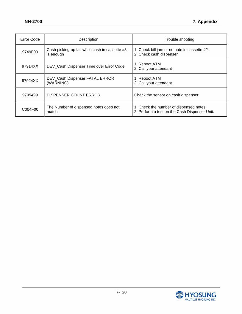
NH-2700 7. Appendix
7- 20
Error Code Description Trouble shooting
9749F00 Cash picking-up fail while cash in cassette #3 is enough
1. Check bill jam or no note in cassette #2 2. Check cash dispenser
97914XX DEV_Cash Dispenser Time over Error Code 1. Reboot ATM 2. Call your attendant
97924XX DEV_Cash Dispenser FATAL ERROR (WARNING)
1. Reboot ATM 2. Call your attendant
9799499 DISPENSER COUNT ERROR Check the sensor on cash dispenser
C004F00 The Number of dispensed notes does not match
1. Check the number of dispensed notes. 2. Perform a test on the Cash Dispenser Unit.
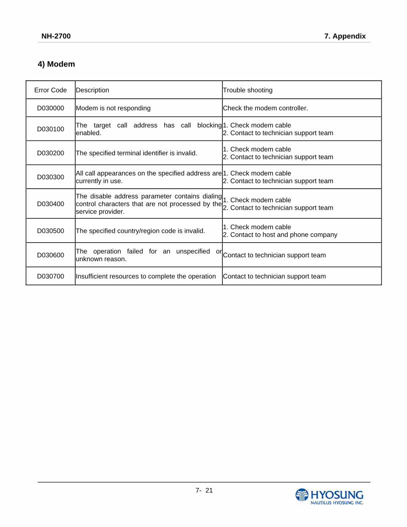
NH-2700 7. Appendix
7- 21
4) Modem
Error Code Description Trouble shooting
D030000 Modem is not responding Check the modem controller.
D030100 The target call address has call blocking enabled.
1. Check modem cable 2. Contact to technician support team
D030200 The specified terminal identifier is invalid. 1. Check modem cable 2. Contact to technician support team
D030300 All call appearances on the specified address are currently in use.
1. Check modem cable 2. Contact to technician support team
D030400 The disable address parameter contains dialing control characters that are not processed by the service provider.
1. Check modem cable 2. Contact to technician support team
D030500 The specified country/region code is invalid. 1. Check modem cable 2. Contact to host and phone company
D030600 The operation failed for an unspecified orunknown reason. Contact to technician support team
D030700 Insufficient resources to complete the operation Contact to technician support team
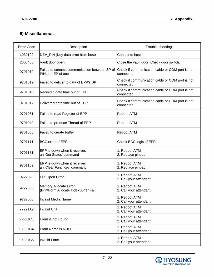
NH-2700 7. Appendix
7- 22
5) Miscellaneous
Error Code Description Trouble shooting
1030100 DEV_PIN (Key data error from host) Contact to host
2000400 Vault door open Close the vault door. Check door switch.
9701010 Failed to connect communication between SP of PIN and EP of one
Check if communication cable or COM port is not connected
9701012 Failed to deliver to data of EPP’s SP Check if communication cable or COM port is not connected
9701016 Received data time out of EPP Check if communication cable or COM port is not connected
9701017 Delivered data time out of EPP Check if communication cable or COM port is not connected
9701031 Failed to read Register of EPP Reboot ATM
9701040 Failed to produce Thread of EPP Reboot ATM
9701060 Failed to create buffer Reboot ATM
9701111 BCC error of EPP Check BCC logic of EPP
9701151 EPP is down when it receives an 'Get Status' command
1. Reboot ATM 2. Replace pinpad
9701152 EPP is down when it receives an 'Clear Func Key' command
1. Reboot ATM 2. Replace pinpad
9722020 File Open Error 1. Reboot ATM 2. Call your attendant
9722060 Memory Allocate Error (PrintForm Allocate IndexBuffer Fail)
1. Reboot ATM 2. Call your attendant
9722068 Invalid Media Name 1. Reboot ATM 2. Call your attendant
97221A2 Invalid Unit 1. Reboot ATM 2. Call your attendant
97221C1 Form is not Found 1. Reboot ATM 2. Call your attendant
97221C4 Form Name is NULL 1. Reboot ATM 2. Call your attendant
97221C5 Invalid Form 1. Reboot ATM 2. Call your attendant
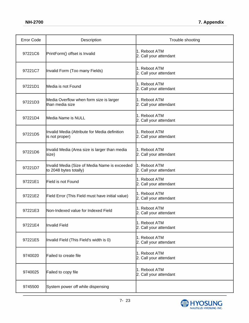
NH-2700 7. Appendix
7- 23
Error Code Description Trouble shooting
97221C6 PrintForm() offset is Invalid 1. Reboot ATM 2. Call your attendant
97221C7 Invalid Form (Too many Fields) 1. Reboot ATM 2. Call your attendant
97221D1 Media is not Found 1. Reboot ATM 2. Call your attendant
97221D3 Media Overflow when form size is larger than media size
1. Reboot ATM 2. Call your attendant
97221D4 Media Name is NULL 1. Reboot ATM 2. Call your attendant
97221D5 Invalid Media (Attribute for Media definition is not proper)
1. Reboot ATM 2. Call your attendant
97221D6 Invalid Media (Area size is larger than media size)
1. Reboot ATM 2. Call your attendant
97221D7 Invalid Media (Size of Media Name is exceededto 2048 bytes totally)
1. Reboot ATM 2. Call your attendant
97221E1 Field is not Found 1. Reboot ATM 2. Call your attendant
97221E2 Field Error (This Field must have initial value) 1. Reboot ATM 2. Call your attendant
97221E3 Non-Indexed value for Indexed Field 1. Reboot ATM 2. Call your attendant
97221E4 Invalid Field 1. Reboot ATM 2. Call your attendant
97221E5 Invalid Field (This Field's width is 0) 1. Reboot ATM 2. Call your attendant
9740020 Failed to create file 1. Reboot ATM 2. Call your attendant
9740025 Failed to copy file 1. Reboot ATM 2. Call your attendant
9745500 System power off while dispensing
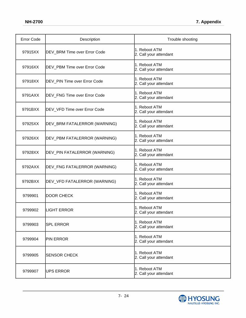
NH-2700 7. Appendix
7- 24
Error Code Description Trouble shooting
97915XX DEV_BRM Time over Error Code 1. Reboot ATM 2. Call your attendant
97916XX DEV_PBM Time over Error Code 1. Reboot ATM 2. Call your attendant
97918XX DEV_PIN Time over Error Code 1. Reboot ATM 2. Call your attendant
9791AXX DEV_FNG Time over Error Code 1. Reboot ATM 2. Call your attendant
9791BXX DEV_VFD Time over Error Code 1. Reboot ATM 2. Call your attendant
97925XX DEV_BRM FATALERROR (WARNING) 1. Reboot ATM 2. Call your attendant
97926XX DEV_PBM FATALERROR (WARNING) 1. Reboot ATM 2. Call your attendant
97928XX DEV_PIN FATALERROR (WARNING) 1. Reboot ATM 2. Call your attendant
9792AXX DEV_FNG FATALERROR (WARNING) 1. Reboot ATM 2. Call your attendant
9792BXX DEV_VFD FATALERROR (WARNING) 1. Reboot ATM 2. Call your attendant
9799901 DOOR CHECK 1. Reboot ATM 2. Call your attendant
9799902 LIGHT ERROR 1. Reboot ATM 2. Call your attendant
9799903 SPL ERROR 1. Reboot ATM 2. Call your attendant
9799904 PIN ERROR 1. Reboot ATM 2. Call your attendant
9799905 SENSOR CHECK 1. Reboot ATM 2. Call your attendant
9799907 UPS ERROR 1. Reboot ATM 2. Call your attendant
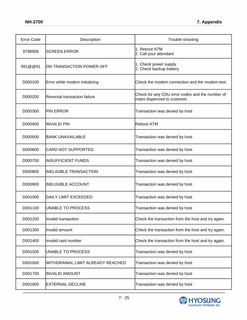
NH-2700 7. Appendix
7- 25
Error Code Description Trouble shooting
9799908 SCREEN ERROR 1. Reboot ATM 2. Call your attendant
991@@91 ON TRANSACTION POWER OFF 1. Check power supply 2. Check backup battery
D000100 Error while modem initializing Check the modem connection and the modem test.
D000200 Reversal transaction failure Check for any CDU error codes and the number of notes dispensed to customer.
D000300 PIN ERROR Transaction was denied by host
D000400 INVALID PIN Reboot ATM
D000500 BANK UNAVAILABLE Transaction was denied by host
D000600 CARD NOT SUPPORTED Transaction was denied by host
D000700 INSUFFICIENT FUNDS Transaction was denied by host
D000800 INELIGIBLE TRANSACTION Transaction was denied by host
D000900 INELIGIBLE ACCOUNT Transaction was denied by host
D001000 DAILY LIMIT EXCEEDED Transaction was denied by host
D001100 UNABLE TO PROCESS Transaction was denied by host
D001200 Invalid transaction Check the transaction from the host and try again.
D001300 Invalid amount Check the transaction from the host and try again.
D001400 Invalid card number Check the transaction from the host and try again.
D001500 UNABLE TO PROCESS Transaction was denied by host
D001600 WITHDRAWAL LIMIT ALREADY REACHED Transaction was denied by host
D001700 INVALID AMOUNT Transaction was denied by host
D001800 EXTERNAL DECLINE Transaction was denied by host
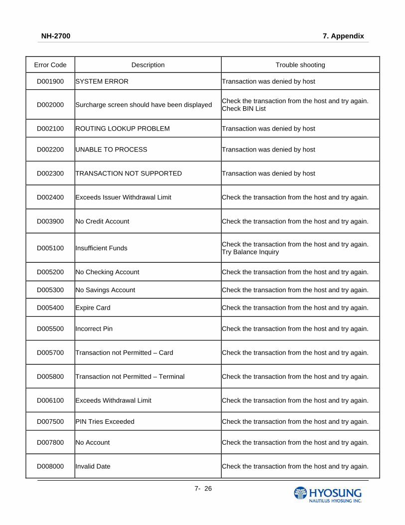
NH-2700 7. Appendix
7- 26
Error Code Description Trouble shooting
D001900 SYSTEM ERROR Transaction was denied by host
D002000 Surcharge screen should have been displayed Check the transaction from the host and try again. Check BIN List
D002100 ROUTING LOOKUP PROBLEM Transaction was denied by host
D002200 UNABLE TO PROCESS Transaction was denied by host
D002300 TRANSACTION NOT SUPPORTED Transaction was denied by host
D002400 Exceeds Issuer Withdrawal Limit Check the transaction from the host and try again.
D003900 No Credit Account Check the transaction from the host and try again.
D005100 Insufficient Funds Check the transaction from the host and try again. Try Balance Inquiry
D005200 No Checking Account Check the transaction from the host and try again.
D005300 No Savings Account Check the transaction from the host and try again.
D005400 Expire Card Check the transaction from the host and try again.
D005500 Incorrect Pin Check the transaction from the host and try again.
D005700 Transaction not Permitted – Card Check the transaction from the host and try again.
D005800 Transaction not Permitted – Terminal Check the transaction from the host and try again.
D006100 Exceeds Withdrawal Limit Check the transaction from the host and try again.
D007500 PIN Tries Exceeded Check the transaction from the host and try again.
D007800 No Account Check the transaction from the host and try again.
D008000 Invalid Date Check the transaction from the host and try again.
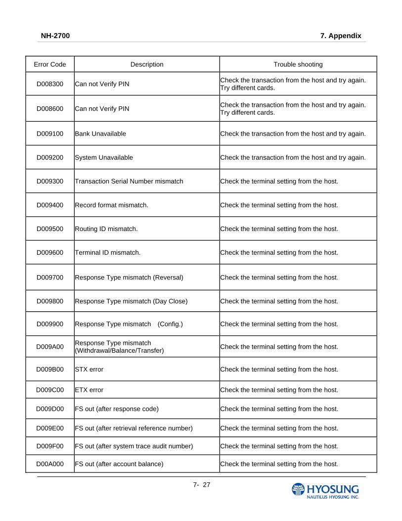
NH-2700 7. Appendix
7- 27
Error Code Description Trouble shooting
D008300 Can not Verify PIN Check the transaction from the host and try again. Try different cards.
D008600 Can not Verify PIN Check the transaction from the host and try again. Try different cards.
D009100 Bank Unavailable Check the transaction from the host and try again.
D009200 System Unavailable Check the transaction from the host and try again.
D009300 Transaction Serial Number mismatch Check the terminal setting from the host.
D009400 Record format mismatch. Check the terminal setting from the host.
D009500 Routing ID mismatch. Check the terminal setting from the host.
D009600 Terminal ID mismatch. Check the terminal setting from the host.
D009700 Response Type mismatch (Reversal) Check the terminal setting from the host.
D009800 Response Type mismatch (Day Close) Check the terminal setting from the host.
D009900 Response Type mismatch (Config.) Check the terminal setting from the host.
D009A00 Response Type mismatch (Withdrawal/Balance/Transfer) Check the terminal setting from the host.
D009B00 STX error Check the terminal setting from the host.
D009C00 ETX error Check the terminal setting from the host.
D009D00 FS out (after response code) Check the terminal setting from the host.
D009E00 FS out (after retrieval reference number) Check the terminal setting from the host.
D009F00 FS out (after system trace audit number) Check the terminal setting from the host.
D00A000 FS out (after account balance) Check the terminal setting from the host.
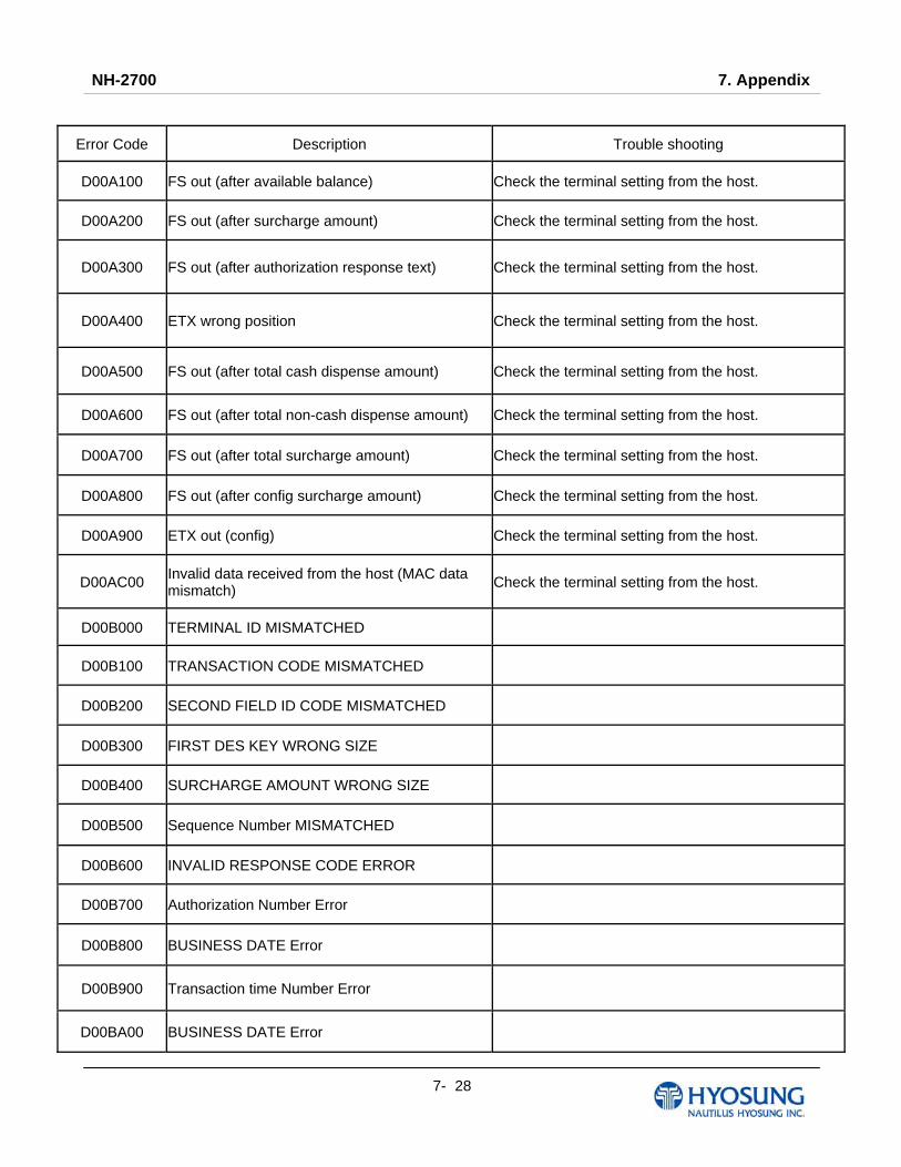
NH-2700 7. Appendix
7- 28
Error Code Description Trouble shooting
D00A100 FS out (after available balance) Check the terminal setting from the host.
D00A200 FS out (after surcharge amount) Check the terminal setting from the host.
D00A300 FS out (after authorization response text) Check the terminal setting from the host.
D00A400 ETX wrong position Check the terminal setting from the host.
D00A500 FS out (after total cash dispense amount) Check the terminal setting from the host.
D00A600 FS out (after total non-cash dispense amount) Check the terminal setting from the host.
D00A700 FS out (after total surcharge amount) Check the terminal setting from the host.
D00A800 FS out (after config surcharge amount) Check the terminal setting from the host.
D00A900 ETX out (config) Check the terminal setting from the host.
D00AC00 Invalid data received from the host (MAC data mismatch) Check the terminal setting from the host.
D00B000 TERMINAL ID MISMATCHED
D00B100 TRANSACTION CODE MISMATCHED
D00B200 SECOND FIELD ID CODE MISMATCHED
D00B300 FIRST DES KEY WRONG SIZE
D00B400 SURCHARGE AMOUNT WRONG SIZE
D00B500 Sequence Number MISMATCHED
D00B600 INVALID RESPONSE CODE ERROR
D00B700 Authorization Number Error
D00B800 BUSINESS DATE Error
D00B900 Transaction time Number Error
D00BA00 BUSINESS DATE Error
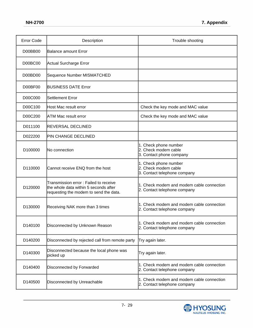
NH-2700 7. Appendix
7- 29
Error Code Description Trouble shooting
D00BB00 Balance amount Error
D00BC00 Actual Surcharge Error
D00BD00 Sequence Number MISMATCHED
D00BF00 BUSINESS DATE Error
D00C000 Settlement Error
D00C100 Host Mac result error Check the key mode and MAC value
D00C200 ATM Mac result error Check the key mode and MAC value
D011100 REVERSAL DECLINED
D022200 PIN CHANGE DECLINED
D100000 No connection 1. Check phone number 2. Check modem cable 3. Contact phone company
D110000 Cannot receive ENQ from the host 1. Check phone number 2. Check modem cable 3. Contact telephone company
D120000 Transmission error : Failed to receive the whole data within 5 seconds after requesting the modem to send the data.
1. Check modem and modem cable connection 2. Contact telephone company
D130000 Receiving NAK more than 3 times 1. Check modem and modem cable connection 2. Contact telephone company
D140100 Disconnected by Unknown Reason 1. Check modem and modem cable connection 2. Contact telephone company
D140200 Disconnected by rejected call from remote party Try again later.
D140300 Disconnected because the local phone was picked up Try again later.
D140400 Disconnected by Forwarded 1. Check modem and modem cable connection 2. Contact telephone company
D140500 Disconnected by Unreachable 1. Check modem and modem cable connection 2. Contact telephone company
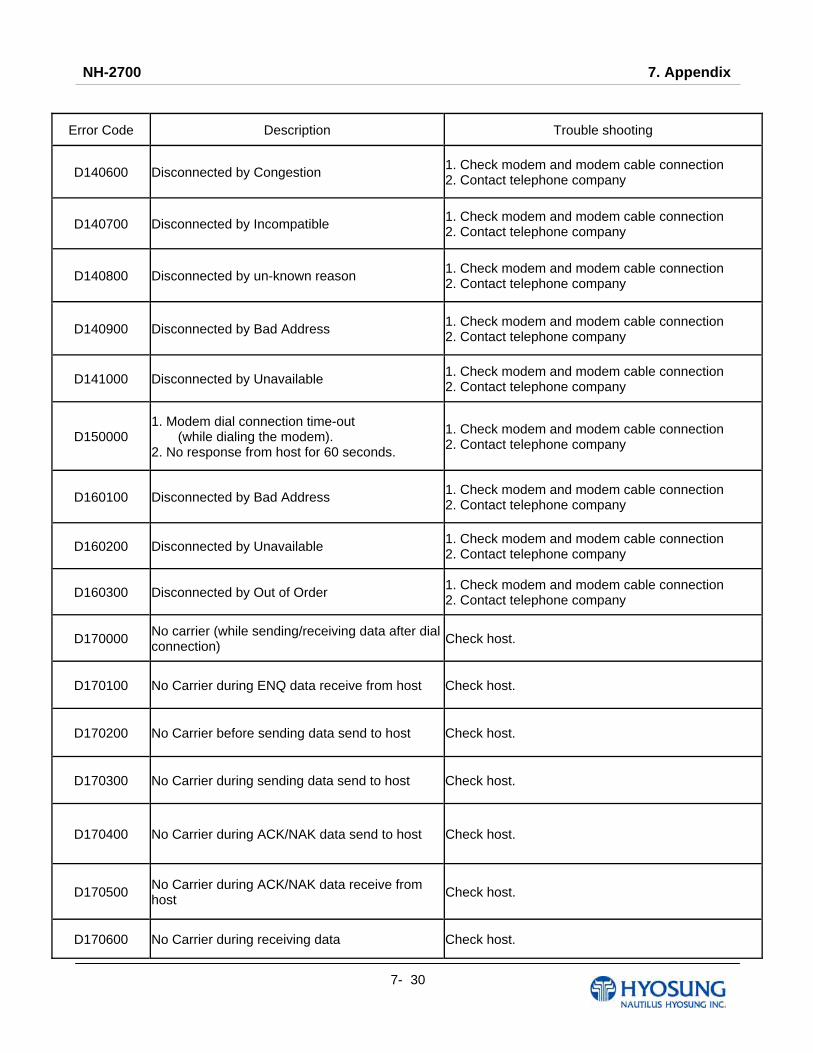
NH-2700 7. Appendix
7- 30
Error Code Description Trouble shooting
D140600 Disconnected by Congestion 1. Check modem and modem cable connection 2. Contact telephone company
D140700 Disconnected by Incompatible 1. Check modem and modem cable connection 2. Contact telephone company
D140800 Disconnected by un-known reason 1. Check modem and modem cable connection 2. Contact telephone company
D140900 Disconnected by Bad Address 1. Check modem and modem cable connection 2. Contact telephone company
D141000 Disconnected by Unavailable 1. Check modem and modem cable connection 2. Contact telephone company
D150000 1. Modem dial connection time-out (while dialing the modem). 2. No response from host for 60 seconds.
1. Check modem and modem cable connection 2. Contact telephone company
D160100 Disconnected by Bad Address 1. Check modem and modem cable connection 2. Contact telephone company
D160200 Disconnected by Unavailable 1. Check modem and modem cable connection 2. Contact telephone company
D160300 Disconnected by Out of Order 1. Check modem and modem cable connection 2. Contact telephone company
D170000 No carrier (while sending/receiving data after dial connection) Check host.
D170100 No Carrier during ENQ data receive from host Check host.
D170200 No Carrier before sending data send to host Check host.
D170300 No Carrier during sending data send to host Check host.
D170400 No Carrier during ACK/NAK data send to host Check host.
D170500 No Carrier during ACK/NAK data receive from host Check host.
D170600 No Carrier during receiving data Check host.
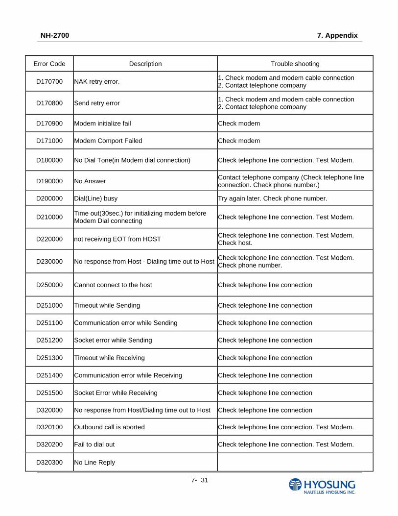
NH-2700 7. Appendix
7- 31
Error Code Description Trouble shooting
D170700 NAK retry error. 1. Check modem and modem cable connection 2. Contact telephone company
D170800 Send retry error 1. Check modem and modem cable connection 2. Contact telephone company
D170900 Modem initialize fail Check modem
D171000 Modem Comport Failed Check modem
D180000 No Dial Tone(in Modem dial connection) Check telephone line connection. Test Modem.
D190000 No Answer Contact telephone company (Check telephone line connection. Check phone number.)
D200000 Dial(Line) busy Try again later. Check phone number.
D210000 Time out(30sec.) for initializing modem before Modem Dial connecting Check telephone line connection. Test Modem.
D220000 not receiving EOT from HOST Check telephone line connection. Test Modem. Check host.
D230000 No response from Host - Dialing time out to Host Check telephone line connection. Test Modem. Check phone number.
D250000 Cannot connect to the host Check telephone line connection
D251000 Timeout while Sending Check telephone line connection
D251100 Communication error while Sending Check telephone line connection
D251200 Socket error while Sending Check telephone line connection
D251300 Timeout while Receiving Check telephone line connection
D251400 Communication error while Receiving Check telephone line connection
D251500 Socket Error while Receiving Check telephone line connection
D320000 No response from Host/Dialing time out to Host Check telephone line connection
D320100 Outbound call is aborted Check telephone line connection. Test Modem.
D320200 Fail to dial out Check telephone line connection. Test Modem.
D320300 No Line Reply

NH-2700 7. Appendix
7- 32
Error Code Description Trouble shooting
D320400 Get Line ID Failed
D320500 Modem Comport Failed
D320600 Call Failed
D320700 No Answer
D320800 Modem Call Other Error
D410000 CRC Mismatch Check telephone line connection
D410100 No CRC Received Make sure that the host is using CRC
DA0xxx0 Host Denial Error Refer to E7. Description for error code organization
F000100 Number of Bill is not inputted Enter number of bill. (required)
F000200 Parameter is not properly set (Surcharge Owner) Enter surcharge owner. (required)
F000300 Parameter is not properly set (Surcharge Amount) Enter surcharge amount. (required)
F000400 Parameter is not properly set (Adver. Text refreshing timer) Enter Ad text refresh timer.
F000500 Parameter is not properly set (Advertisement text) Enter Ad text.
F000600 Parameter is not properly set (Dispense limit) Enter Dispense limit.
F000700 Parameter is not properly set (Denomination) Enter Denomination. (required)
F000800 Parameter is not properly set (Fast Cash) Enter Fast Cash amount.
F000900 Master Key Index invalid Check Master key index.
F000A00 Master Key empty Enter Master key. (required)
F000B00 Host Phone Number is not inputted Enter Host phone number. (required)
F000C00 Error Retry Timer is not inputted Enter Retry timer.
F000D00 RMS Password is not inputted in RMS Enable Enter RMS password.
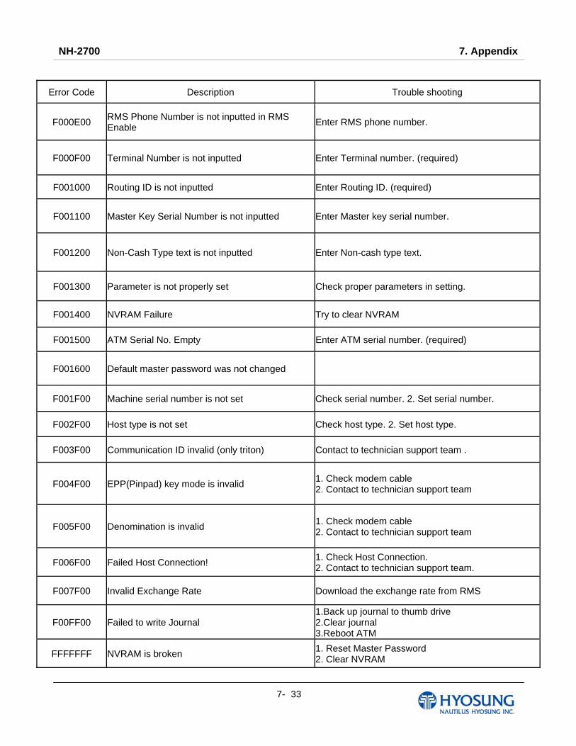
NH-2700 7. Appendix
7- 33
Error Code Description Trouble shooting
F000E00 RMS Phone Number is not inputted in RMS Enable Enter RMS phone number.
F000F00 Terminal Number is not inputted Enter Terminal number. (required)
F001000 Routing ID is not inputted Enter Routing ID. (required)
F001100 Master Key Serial Number is not inputted Enter Master key serial number.
F001200 Non-Cash Type text is not inputted Enter Non-cash type text.
F001300 Parameter is not properly set Check proper parameters in setting.
F001400 NVRAM Failure Try to clear NVRAM
F001500 ATM Serial No. Empty Enter ATM serial number. (required)
F001600 Default master password was not changed
F001F00 Machine serial number is not set Check serial number. 2. Set serial number.
F002F00 Host type is not set Check host type. 2. Set host type.
F003F00 Communication ID invalid (only triton) Contact to technician support team .
F004F00 EPP(Pinpad) key mode is invalid 1. Check modem cable 2. Contact to technician support team
F005F00 Denomination is invalid 1. Check modem cable 2. Contact to technician support team
F006F00 Failed Host Connection! 1. Check Host Connection. 2. Contact to technician support team.
F007F00 Invalid Exchange Rate Download the exchange rate from RMS
F00FF00 Failed to write Journal 1.Back up journal to thumb drive 2.Clear journal 3.Reboot ATM
FFFFFFF NVRAM is broken 1. Reset Master Password 2. Clear NVRAM
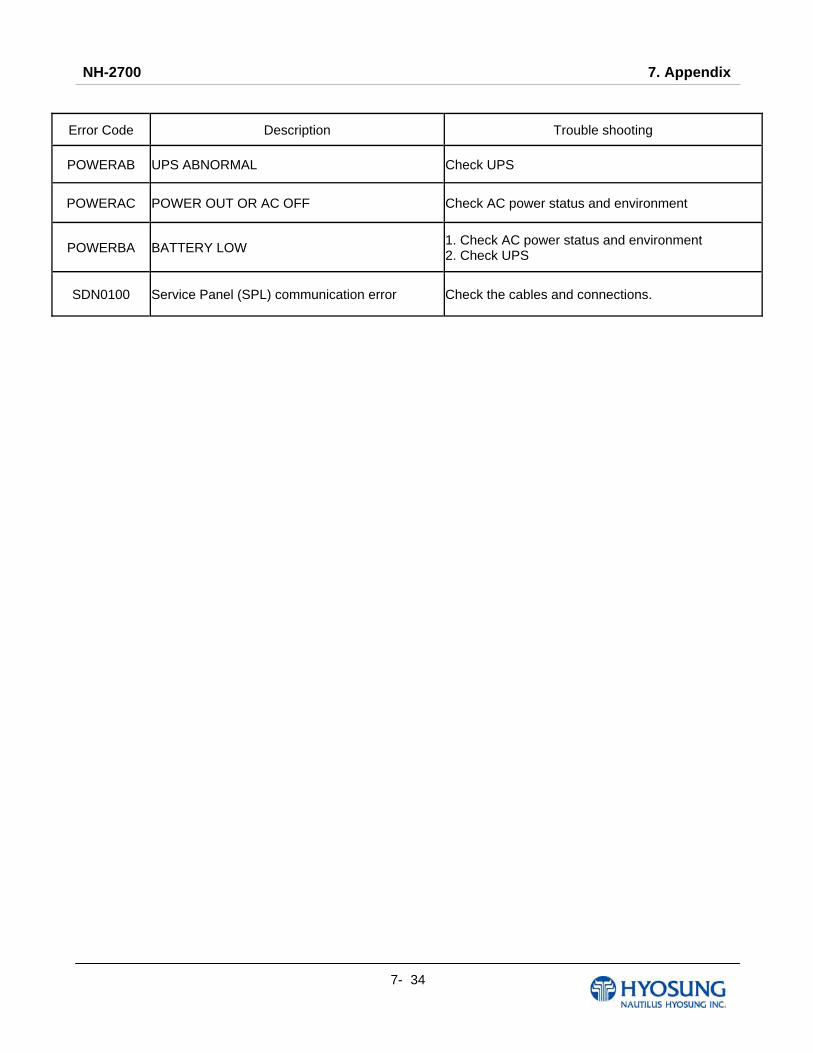
NH-2700 7. Appendix
7- 34
Error Code Description Trouble shooting
POWERAB UPS ABNORMAL Check UPS
POWERAC POWER OUT OR AC OFF Check AC power status and environment
POWERBA BATTERY LOW 1. Check AC power status and environment 2. Check UPS
SDN0100 Service Panel (SPL) communication error Check the cables and connections.
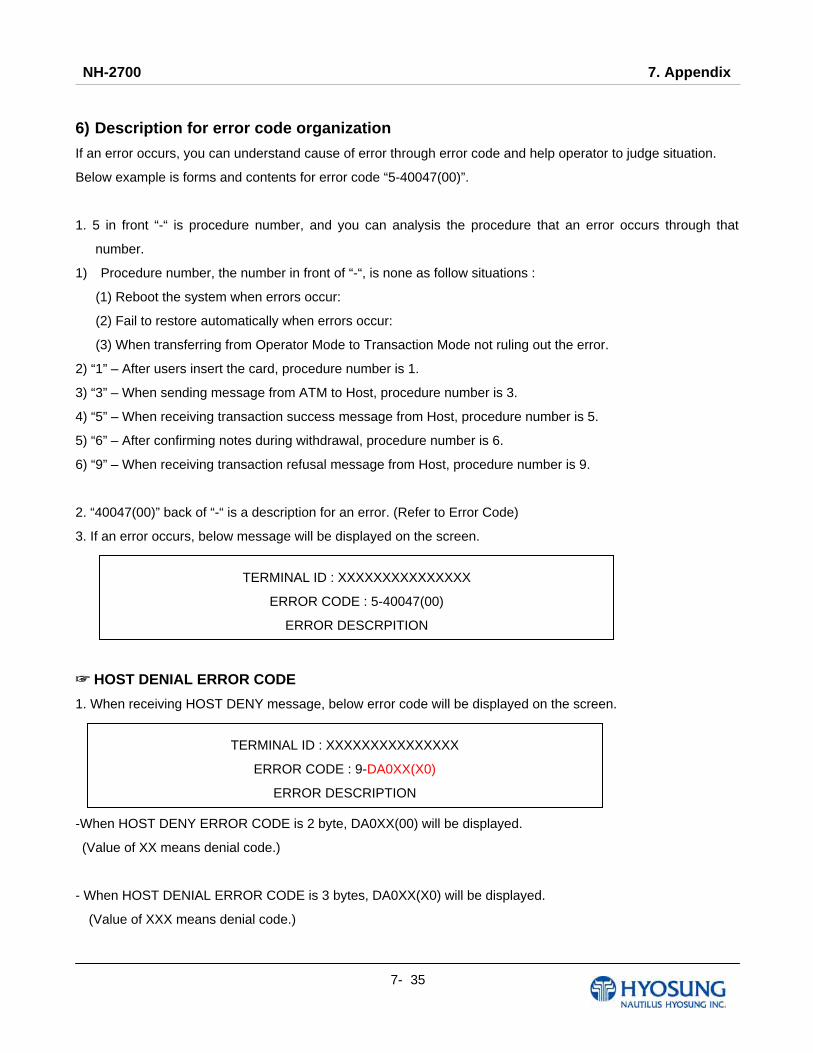
NH-2700 7. Appendix
7- 35
6) Description for error code organization
If an error occurs, you can understand cause of error through error code and help operator to judge situation.
Below example is forms and contents for error code “5-40047(00)”.
1. 5 in front “-“ is procedure number, and you can analysis the procedure that an error occurs through that
number.
1) Procedure number, the number in front of “-“, is none as follow situations :
(1) Reboot the system when errors occur:
(2) Fail to restore automatically when errors occur:
(3) When transferring from Operator Mode to Transaction Mode not ruling out the error.
2) “1” – After users insert the card, procedure number is 1.
3) “3” – When sending message from ATM to Host, procedure number is 3.
4) “5” – When receiving transaction success message from Host, procedure number is 5.
5) “6” – After confirming notes during withdrawal, procedure number is 6.
6) “9” – When receiving transaction refusal message from Host, procedure number is 9.
2. “40047(00)” back of “-“ is a description for an error. (Refer to Error Code)
3. If an error occurs, below message will be displayed on the screen.
HOST DE☞ NIAL ERROR CODE
1. When receiving HOST DENY message, below error code will be displayed on the screen.
-When HOST DENY ERROR CODE is 2 byte, DA0XX(00) will be displayed.
(Value of XX means denial code.)
- When HOST DENIAL ERROR CODE is 3 bytes, DA0XX(X0) will be displayed.
(Value of XXX means denial code.)
TERMINAL ID : XXXXXXXXXXXXXXX
ERROR CODE : 5-40047(00)
ERROR DESCRPITION
TERMINAL ID : XXXXXXXXXXXXXXX
ERROR CODE : 9-DA0XX(X0)
ERROR DESCRIPTION
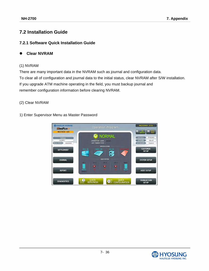
NH-2700 7. Appendix
7- 36
7.2 Installation Guide 7.2.1 Software Quick Installation Guide
Clear NVRAM
(1) NVRAM
There are many important data in the NVRAM such as journal and configuration data.
To clear all of configuration and journal data to the initial status, clear NVRAM after S/W installation.
If you upgrade ATM machine operating in the field, you must backup journal and
remember configuration information before clearing NVRAM.
(2) Clear NVRAM
1) Enter Supervisor Menu as Master Password

NH-2700 7. Appendix
7- 37
2) Select “SYSTEM SETUP” menu
3) Select “SYSTEM CONTROL” menu

NH-2700 7. Appendix
7- 38
4) Select “CLEAR ALL” menu.
5) Confirm and select “Yes” menu.
6) All NVRAM data will be cleared and ATM will be automatically rebooted.
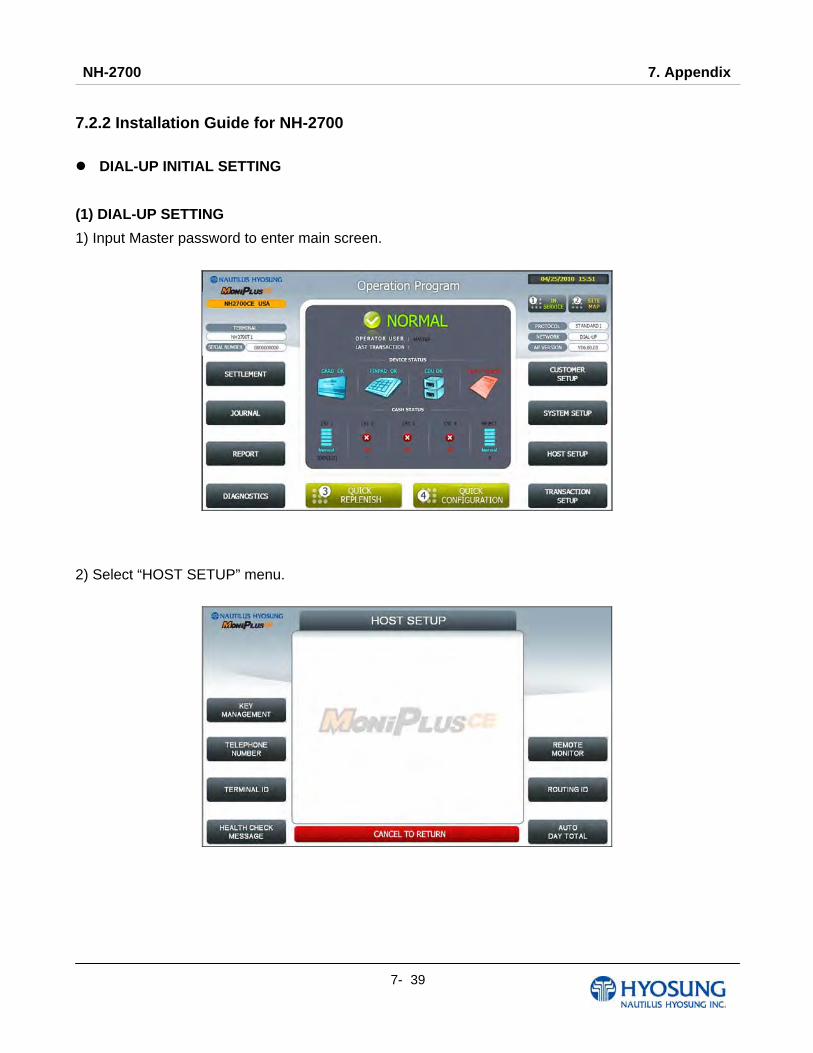
NH-2700 7. Appendix
7- 39
7.2.2 Installation Guide for NH-2700
DIAL-UP INITIAL SETTING
(1) DIAL-UP SETTING
1) Input Master password to enter main screen.
2) Select “HOST SETUP” menu.
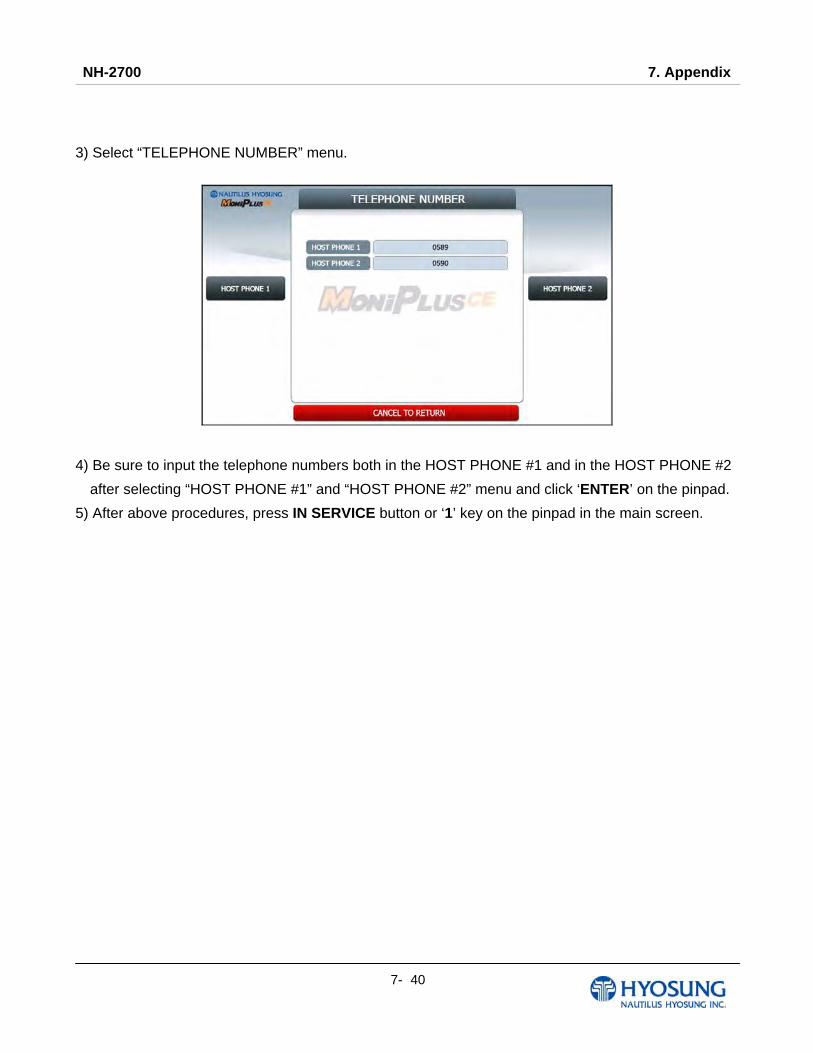
NH-2700 7. Appendix
7- 40
3) Select “TELEPHONE NUMBER” menu.
4) Be sure to input the telephone numbers both in the HOST PHONE #1 and in the HOST PHONE #2
after selecting “HOST PHONE #1” and “HOST PHONE #2” menu and click ‘ENTER’ on the pinpad.
5) After above procedures, press IN SERVICE button or ‘1’ key on the pinpad in the main screen.
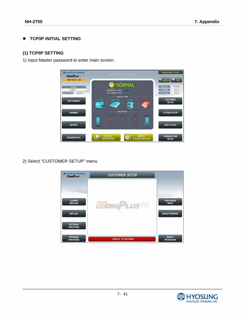
NH-2700 7. Appendix
7- 41
TCP/IP INITIAL SETTING
(1) TCP/IP SETTING
1) Input Master password to enter main screen.
2) Select “CUSTOMER SETUP” menu.
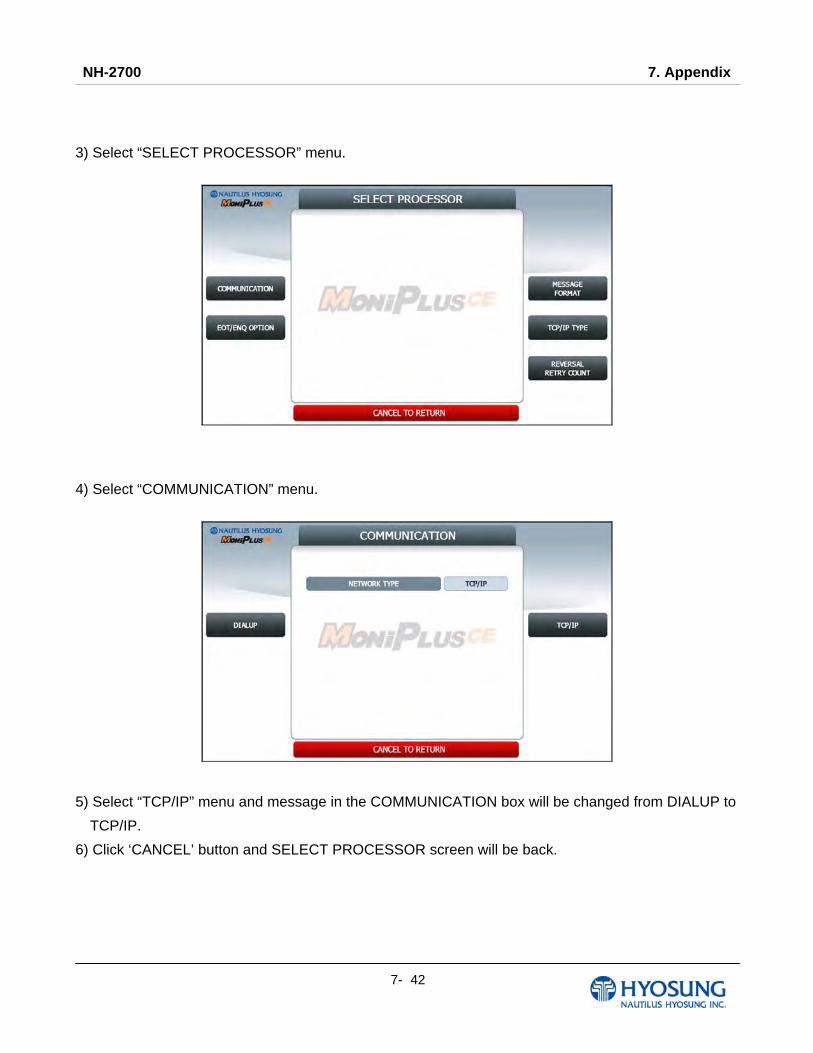
NH-2700 7. Appendix
7- 42
3) Select “SELECT PROCESSOR” menu.
4) Select “COMMUNICATION” menu.
5) Select “TCP/IP” menu and message in the COMMUNICATION box will be changed from DIALUP to
TCP/IP.
6) Click ‘CANCEL’ button and SELECT PROCESSOR screen will be back.

NH-2700 7. Appendix
7- 43
7) Select “MESSAGE FORMAT” menu in the SELECT PROCESSOR screen.
8) Select “STANDARD1” menu in the MESSAGE FORMAT screen. Click ‘CANCEL’ button to go
SELECT PROCESSOR screen.
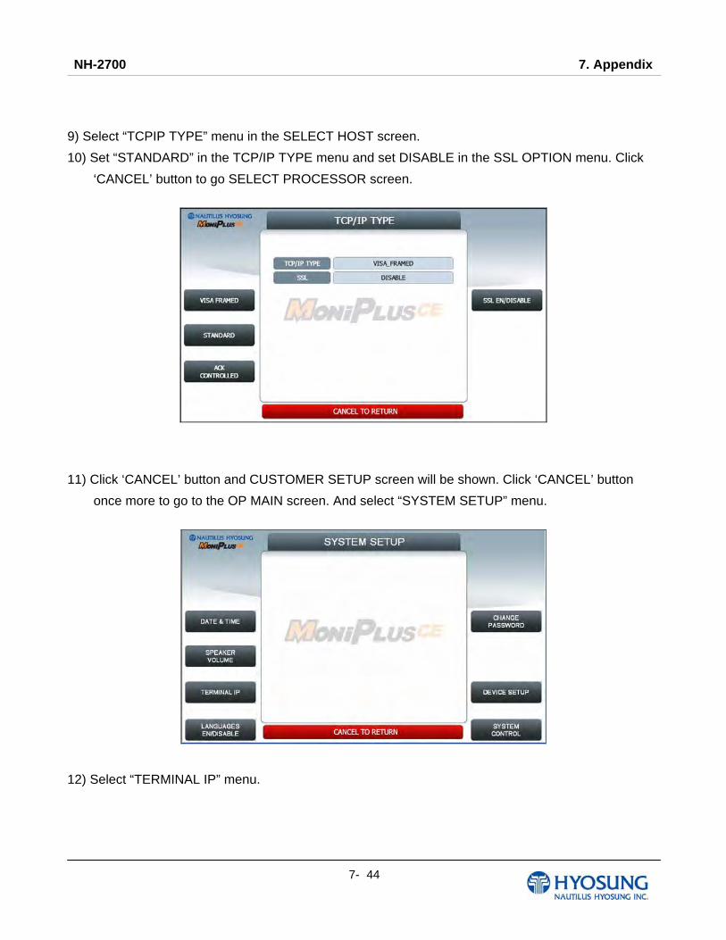
NH-2700 7. Appendix
7- 44
9) Select “TCPIP TYPE” menu in the SELECT HOST screen.
10) Set “STANDARD” in the TCP/IP TYPE menu and set DISABLE in the SSL OPTION menu. Click
‘CANCEL’ button to go SELECT PROCESSOR screen.
11) Click ‘CANCEL’ button and CUSTOMER SETUP screen will be shown. Click ‘CANCEL’ button
once more to go to the OP MAIN screen. And select “SYSTEM SETUP” menu.
12) Select “TERMINAL IP” menu.
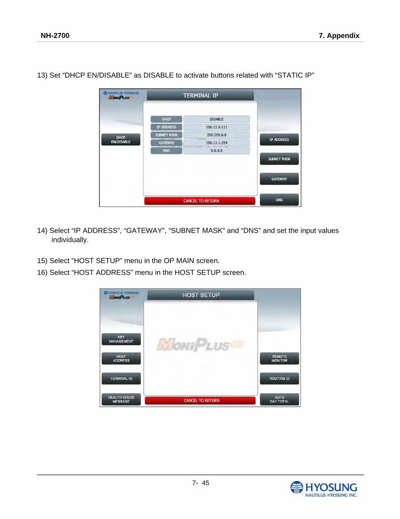
NH-2700 7. Appendix
7- 45
13) Set “DHCP EN/DISABLE” as DISABLE to activate buttons related with “STATIC IP”
14) Select “IP ADDRESS”, “GATEWAY”, “SUBNET MASK” and “DNS” and set the input values
individually.
15) Select “HOST SETUP” menu in the OP MAIN screen.
16) Select “HOST ADDRESS” menu in the HOST SETUP screen.
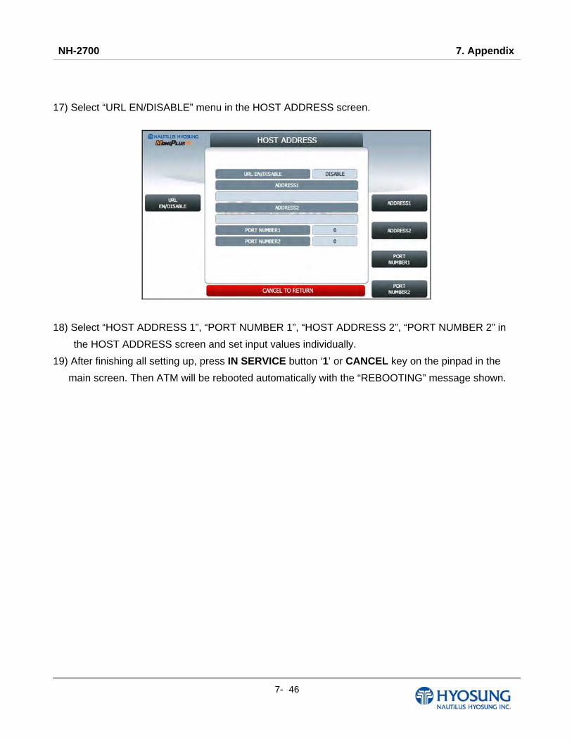
NH-2700 7. Appendix
7- 46
17) Select “URL EN/DISABLE” menu in the HOST ADDRESS screen.
18) Select “HOST ADDRESS 1”, “PORT NUMBER 1”, “HOST ADDRESS 2”, “PORT NUMBER 2” in
the HOST ADDRESS screen and set input values individually.
19) After finishing all setting up, press IN SERVICE button ‘1’ or CANCEL key on the pinpad in the
main screen. Then ATM will be rebooted automatically with the “REBOOTING” message shown.
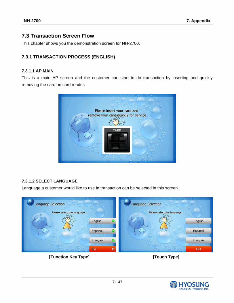
NH-2700 7. Appendix
7- 47
7.3 Transaction Screen Flow This chapter shows you the demonstration screen for NH-2700.
7.3.1 TRANSACTION PROCESS (ENGLISH)
7.3.1.1 AP MAIN
This is a main AP screen and the customer can start to do transaction by inserting and quickly
removing the card on card reader.
7.3.1.2 SELECT LANGUAGE
Language a customer would like to use in transaction can be selected in this screen.
[Function Key Type] [Touch Type]

NH-2700 7. Appendix
7- 48
7.3.1.3 ENTER PIN
This screen is to enter PIN of customer's card
7.3.1.4 SELECT TRANSACTION
This screen is to select transaction type the customer wants to transact such as withdrawal, balance
inquiry and transfer is selected in this screen.
[Function Key Type] [Touch Type]

NH-2700 7. Appendix
7- 49
7.3.1.4.1 WITHDRAWAL: FEE NOTICE
This screen is to show a customer the information of surcharge.
[Function Key Type] [Touch Type]
7.3.1.4.2 WITHDRAWAL: SELECT RECEIPT PRINTING OR NOT
This screen is to ask a customer if he/she wants to get the receipt or not.
[Function Key Type] [Touch Type]

NH-2700 7. Appendix
7- 50
7.3.1.4.3 WITHDRAWAL: SELECT ACCOUNT (Checking, Saving, Credit Card)
This screen is to ask a customer where he/she wants to withdraw in checking, saving, credit card
[Function Key Type] [Touch Type]

NH-2700 7. Appendix
7- 51
7.3.1.4.4 WITHDRAWAL: SELECT THE AMOUNT OF WITHDRAWAL
This screen is to select the amount of withdrawal. If there is not any amount to withdraw, please select
the “OTHER” key and can input the amount the customer would like to withdraw.
1) Amount Selection
[Function Key Type] [Touch Type]
2) Amount Input (Other)
[Function Key Type] [Touch Type]
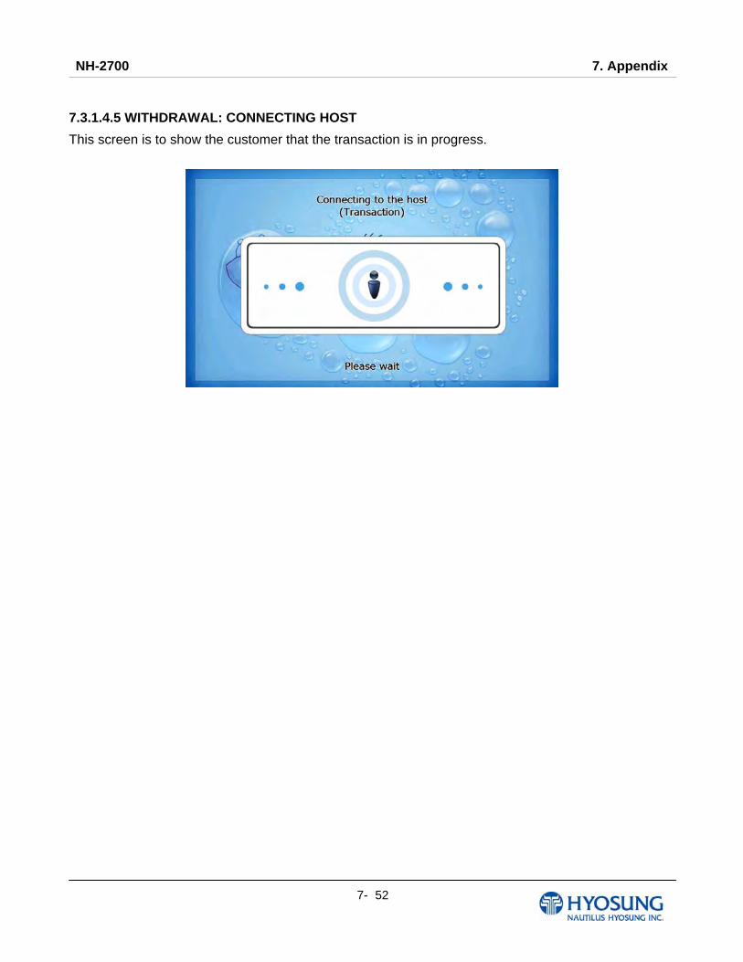
NH-2700 7. Appendix
7- 52
7.3.1.4.5 WITHDRAWAL: CONNECTING HOST
This screen is to show the customer that the transaction is in progress.

NH-2700 7. Appendix
7- 53
7.3.1.4.6 WITHDRAWAL: DISPENSING MONEY AND TAKE MONEY
This screen is to show the customer that his/her request amount is dispensing and to notify the
customer to take his/her money.

NH-2700 7. Appendix
7- 54
7.3.1.4.7 WITHDRAWAL: PRINTING TRANSACTION AND TAKE RECEIPT
This screen is to show the customer that his/her transaction record is printing and to notify the
customer to take his/her receipt.

NH-2700 7. Appendix
7- 55
7.3.1.4.8 WITHDRAWAL: THANK YOU
This screen is to show the customer that the transaction has been successfully completed.
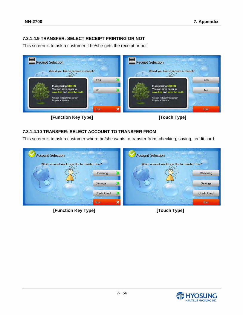
NH-2700 7. Appendix
7- 56
7.3.1.4.9 TRANSFER: SELECT RECEIPT PRINTING OR NOT
This screen is to ask a customer if he/she gets the receipt or not.
[Function Key Type] [Touch Type]
7.3.1.4.10 TRANSFER: SELECT ACCOUNT TO TRANSFER FROM
This screen is to ask a customer where he/she wants to transfer from; checking, saving, credit card
[Function Key Type] [Touch Type]
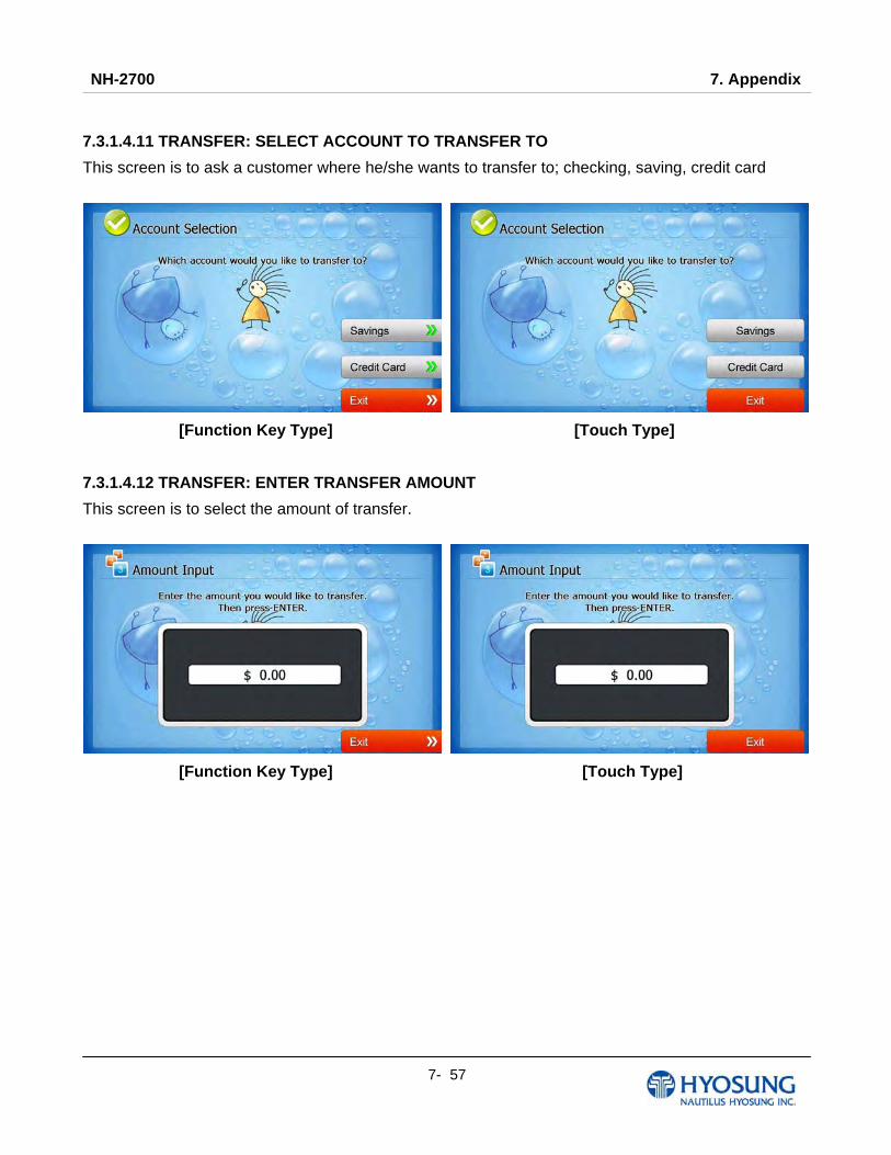
NH-2700 7. Appendix
7- 57
7.3.1.4.11 TRANSFER: SELECT ACCOUNT TO TRANSFER TO
This screen is to ask a customer where he/she wants to transfer to; checking, saving, credit card
[Function Key Type] [Touch Type]
7.3.1.4.12 TRANSFER: ENTER TRANSFER AMOUNT
This screen is to select the amount of transfer.
[Function Key Type] [Touch Type]

NH-2700 7. Appendix
7- 58
7.3.1.4.13 TRANSFER: CONNECTING HOST
This screen is to show the customer that the transaction is in progress.

NH-2700 7. Appendix
7- 59
7.3.1.4.14 TRANSFER: PRINTING TRANSACTION AND TAKE RECEIPT
This screen is to show the customer that his/her transaction record is printing and to notify the
customer to take his/her receipt.
NH-2700 7. Appendix
7- 60
7.3.1.4.15 TRANSFER: THANK YOU
This screen is to show the customer that the transaction has been successfully completed.
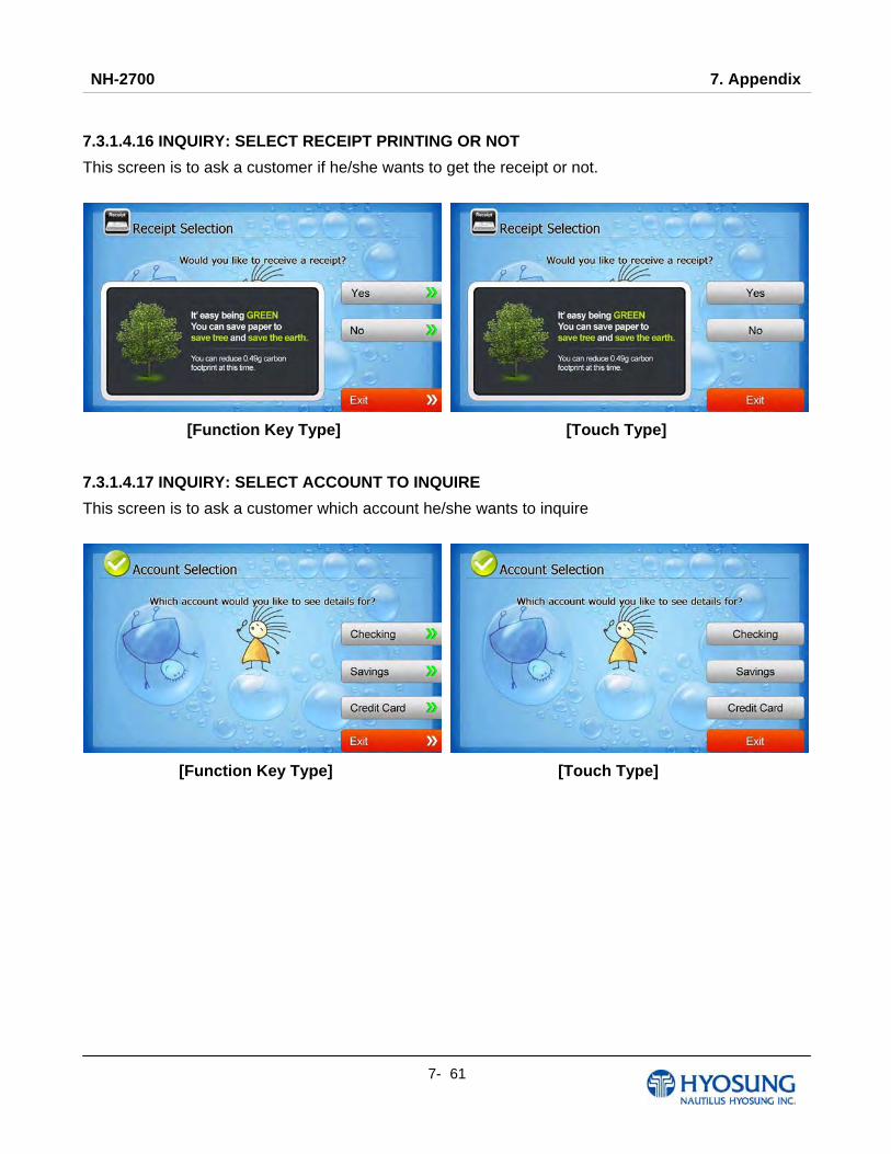
NH-2700 7. Appendix
7- 61
7.3.1.4.16 INQUIRY: SELECT RECEIPT PRINTING OR NOT
This screen is to ask a customer if he/she wants to get the receipt or not.
[Function Key Type] [Touch Type]
7.3.1.4.17 INQUIRY: SELECT ACCOUNT TO INQUIRE
This screen is to ask a customer which account he/she wants to inquire
[Function Key Type] [Touch Type]
NH-2700 7. Appendix
7- 62
7.3.1.4.18 INQUIRY: CONNECTING HOST
This screen is to show the customer that the transaction is in progress.
NH-2700 7. Appendix
7- 63
7.3.1.4.19 INQUIRY: PRINTING TRANSACTION AND TAKE RECEIPT
This screen is to show the customer that his/her transaction record is printing and to notify the
customer to take his/her receipt.

NH-2700 7. Appendix
7- 64
7.3.1.4.20 INQUIRY: THANK YOU
This screen is to show the customer that the transaction has been successfully completed.
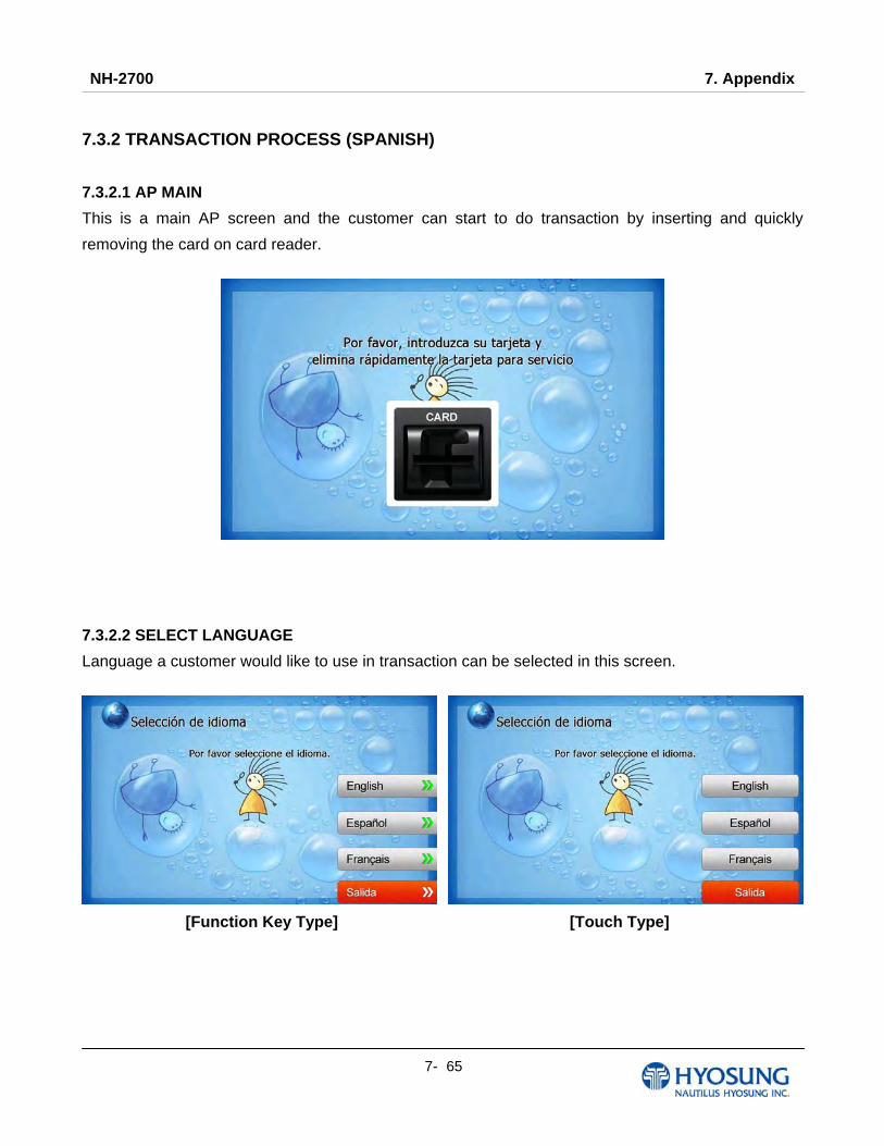
NH-2700 7. Appendix
7- 65
7.3.2 TRANSACTION PROCESS (SPANISH)
7.3.2.1 AP MAIN
This is a main AP screen and the customer can start to do transaction by inserting and quickly
removing the card on card reader.
7.3.2.2 SELECT LANGUAGE
Language a customer would like to use in transaction can be selected in this screen.
[Function Key Type] [Touch Type]
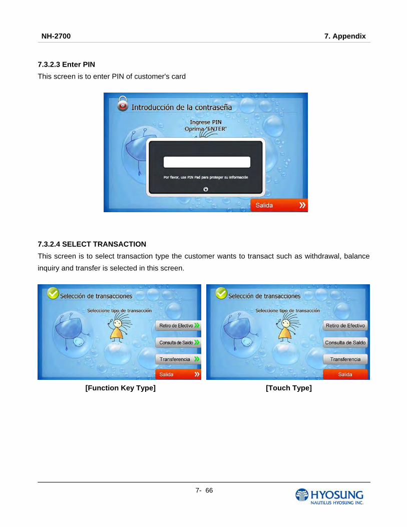
NH-2700 7. Appendix
7- 66
7.3.2.3 Enter PIN
This screen is to enter PIN of customer's card
7.3.2.4 SELECT TRANSACTION
This screen is to select transaction type the customer wants to transact such as withdrawal, balance
inquiry and transfer is selected in this screen.
[Function Key Type] [Touch Type]

NH-2700 7. Appendix
7- 67
7.3.2.4.1 WITHDRAWAL: FEE NOTICE
This screen is to show a customer the information of surcharge.
[Function Key Type] [Touch Type]
7.3.2.4.2 WITHDRAWAL: SELECT RECEIPT PRINTING OR NOT
This screen is to ask a customer if he/she wants to get the receipt or not.
[Function Key Type] [Touch Type]

NH-2700 7. Appendix
7- 68
7.3.2.4.3 WITHDRAWAL: SELECT ACCOUNT (Checking, Saving, Credit Card)
This screen is to ask a customer where he/she wants to withdraw in checking, saving, credit card
[Function Key Type] [Touch Type]

NH-2700 7. Appendix
7- 69
7.3.2.4.4 WITHDRAWAL: SELECT THE AMOUNT OF WITHDRAWAL
This screen is to select the amount of withdrawal. If there is not any amount to withdraw, please select
the “OTHER” key and can input the amount the customer would like to withdraw.
1) Amount Selection
[Function Key Type] [Touch Type]
2) Amount Input (Other)
[Function Key Type] [Touch Type]

NH-2700 7. Appendix
7- 70
7.3.2.4.5 WITHDRAWAL: CONNECTING HOST
This screen is to show the customer that the transaction is in progress.
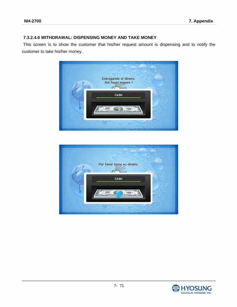
NH-2700 7. Appendix
7- 71
7.3.2.4.6 WITHDRAWAL: DISPENSING MONEY AND TAKE MONEY
This screen is to show the customer that his/her request amount is dispensing and to notify the
customer to take his/her money.

NH-2700 7. Appendix
7- 72
7.3.2.4.7 WITHDRAWAL: PRINTING TRANSACTION AND TAKE RECEIPT
This screen is to show the customer that his/her transaction record is printing and to notify the
customer to take his/her receipt.
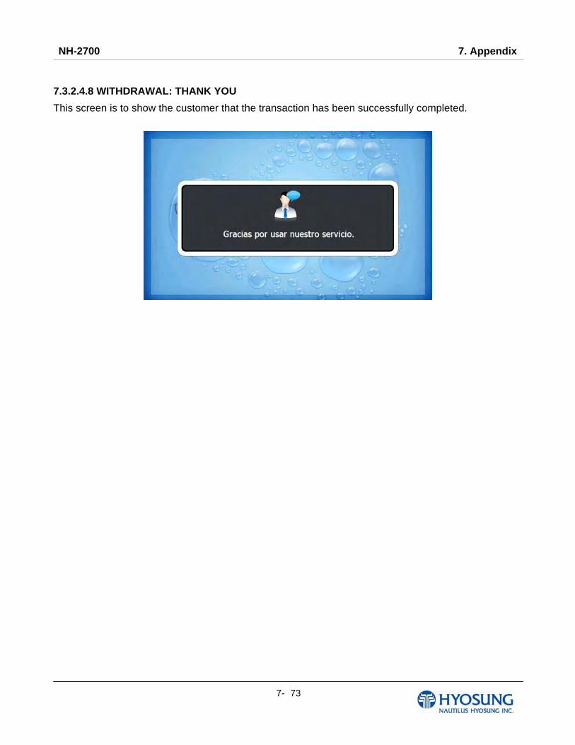
NH-2700 7. Appendix
7- 73
7.3.2.4.8 WITHDRAWAL: THANK YOU
This screen is to show the customer that the transaction has been successfully completed.

NH-2700 7. Appendix
7- 74
7.3.2.4.9 TRANSFER: SELECT RECEIPT PRINTING OR NOT
This screen is to ask a customer if he/she gets the receipt or not.
[Function Key Type] [Touch Type]
7.3.2.4.10 TRANSFER: SELECT ACCOUNT TO TRANSFER FROM
This screen is to ask a customer where he/she wants to transfer from; checking, saving, credit card
[Function Key Type] [Touch Type]
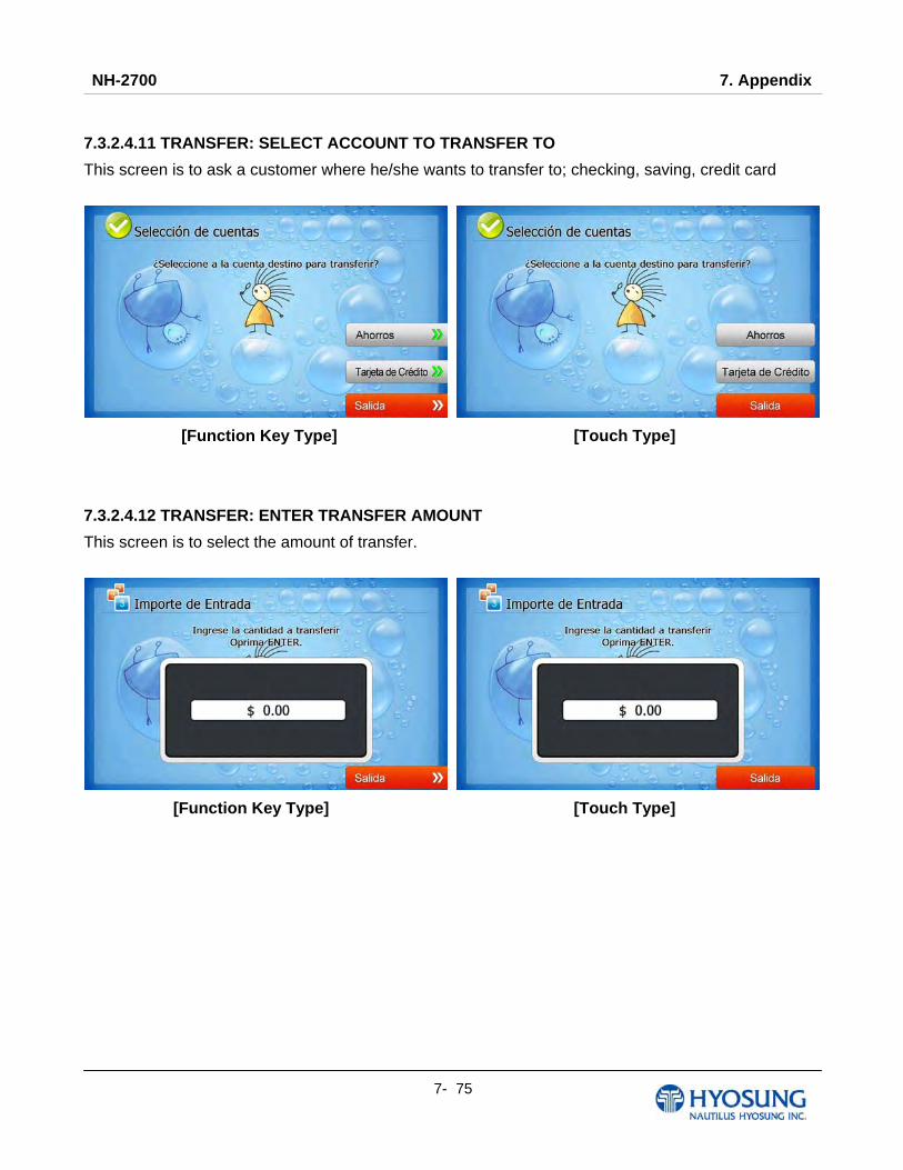
NH-2700 7. Appendix
7- 75
7.3.2.4.11 TRANSFER: SELECT ACCOUNT TO TRANSFER TO
This screen is to ask a customer where he/she wants to transfer to; checking, saving, credit card
[Function Key Type] [Touch Type]
7.3.2.4.12 TRANSFER: ENTER TRANSFER AMOUNT
This screen is to select the amount of transfer.
[Function Key Type] [Touch Type]
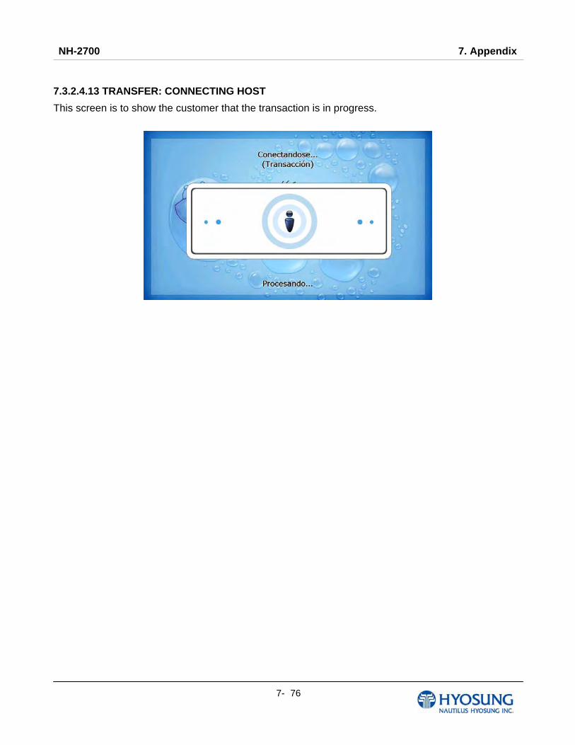
NH-2700 7. Appendix
7- 76
7.3.2.4.13 TRANSFER: CONNECTING HOST
This screen is to show the customer that the transaction is in progress.

NH-2700 7. Appendix
7- 77
7.3.2.4.14 TRANSFER: PRINTING TRANSACTION AND TAKE RECEIPT
This screen is to show the customer that his/her transaction record is printing and to notify the
customer to take his/her receipt.
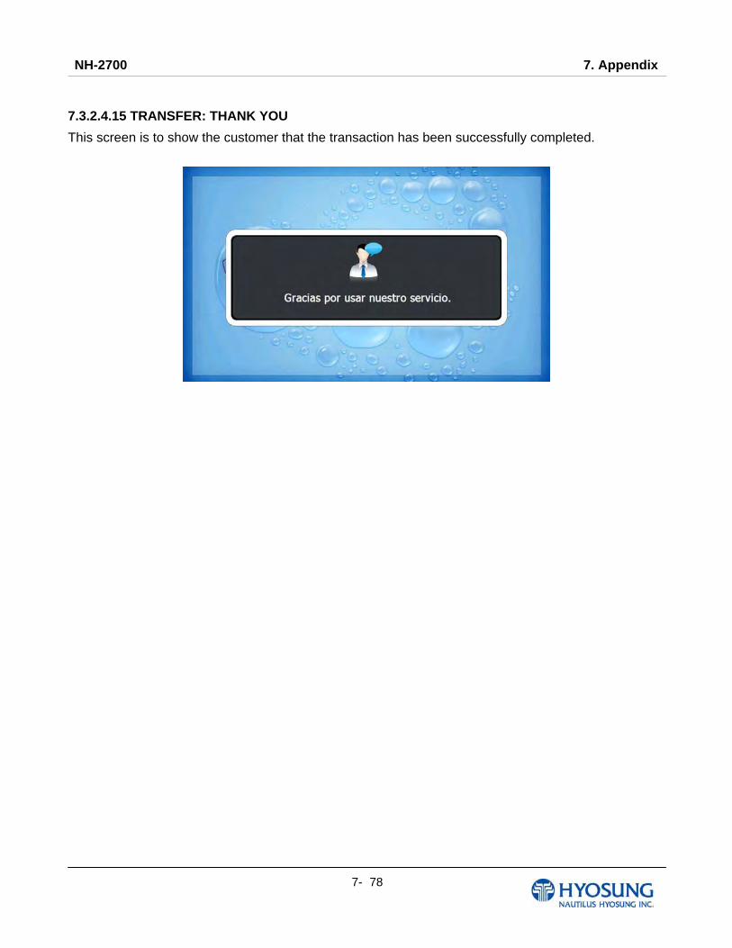
NH-2700 7. Appendix
7- 78
7.3.2.4.15 TRANSFER: THANK YOU
This screen is to show the customer that the transaction has been successfully completed.

NH-2700 7. Appendix
7- 79
7.3.2.4.16 INQUIRY: SELECT RECEIPT PRINTING OR NOT
This screen is to ask a customer if he/she wants to get the receipt or not.
[Function Key Type] [Touch Type]
7.3.2.4.17 INQUIRY: SELECT ACCOUNT TO INQUIRE
This screen is to ask a customer which account he/she wants to inquire
[Function Key Type] [Touch Type]
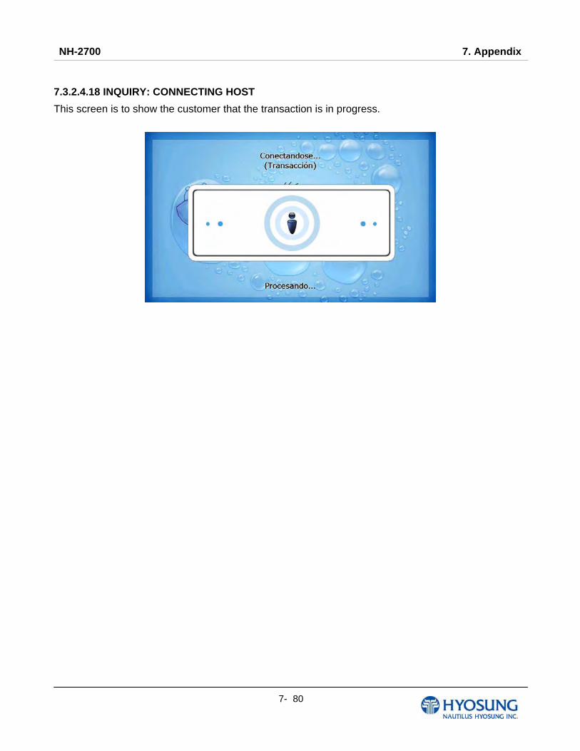
NH-2700 7. Appendix
7- 80
7.3.2.4.18 INQUIRY: CONNECTING HOST
This screen is to show the customer that the transaction is in progress.

NH-2700 7. Appendix
7- 81
7.3.2.4.19 INQUIRY: PRINTING TRANSACTION AND TAKE RECEIPT
This screen is to show the customer that his/her transaction record is printing and to notify the
customer to take his/her receipt.

NH-2700 7. Appendix
7- 82
7.3.2.4.20 INQUIRY: THANK YOU
This screen is to show the customer that the transaction has been successfully completed.
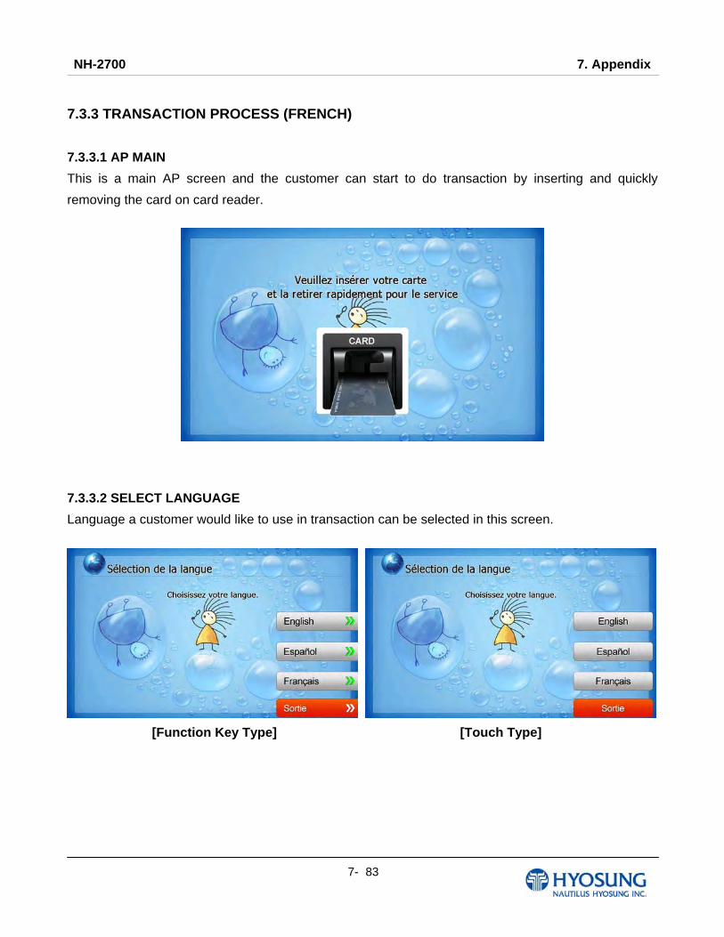
NH-2700 7. Appendix
7- 83
7.3.3 TRANSACTION PROCESS (FRENCH)
7.3.3.1 AP MAIN
This is a main AP screen and the customer can start to do transaction by inserting and quickly
removing the card on card reader.
7.3.3.2 SELECT LANGUAGE
Language a customer would like to use in transaction can be selected in this screen.
[Function Key Type] [Touch Type]

NH-2700 7. Appendix
7- 84
7.3.3.3 Enter PIN
This screen is to enter PIN of customer's card
7.3.3.4 SELECT TRANSACTION
This screen is to select transaction type the customer wants to transact such as withdrawal, balance
inquiry and transfer is selected in this screen.
[Function Key Type] [Touch Type]

NH-2700 7. Appendix
7- 85
7.3.3.4.1 WITHDRAWAL: FEE NOTICE
This screen is to show a customer the information of surcharge.
[Function Key Type] [Touch Type]
7.3.3.4.2 WITHDRAWAL: SELECT RECEIPT PRINTING OR NOT
This screen is to ask a customer if he/she wants to get the receipt or not.
[Function Key Type] [Touch Type]
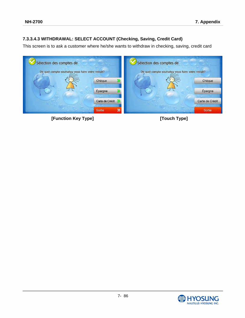
NH-2700 7. Appendix
7- 86
7.3.3.4.3 WITHDRAWAL: SELECT ACCOUNT (Checking, Saving, Credit Card)
This screen is to ask a customer where he/she wants to withdraw in checking, saving, credit card
[Function Key Type] [Touch Type]
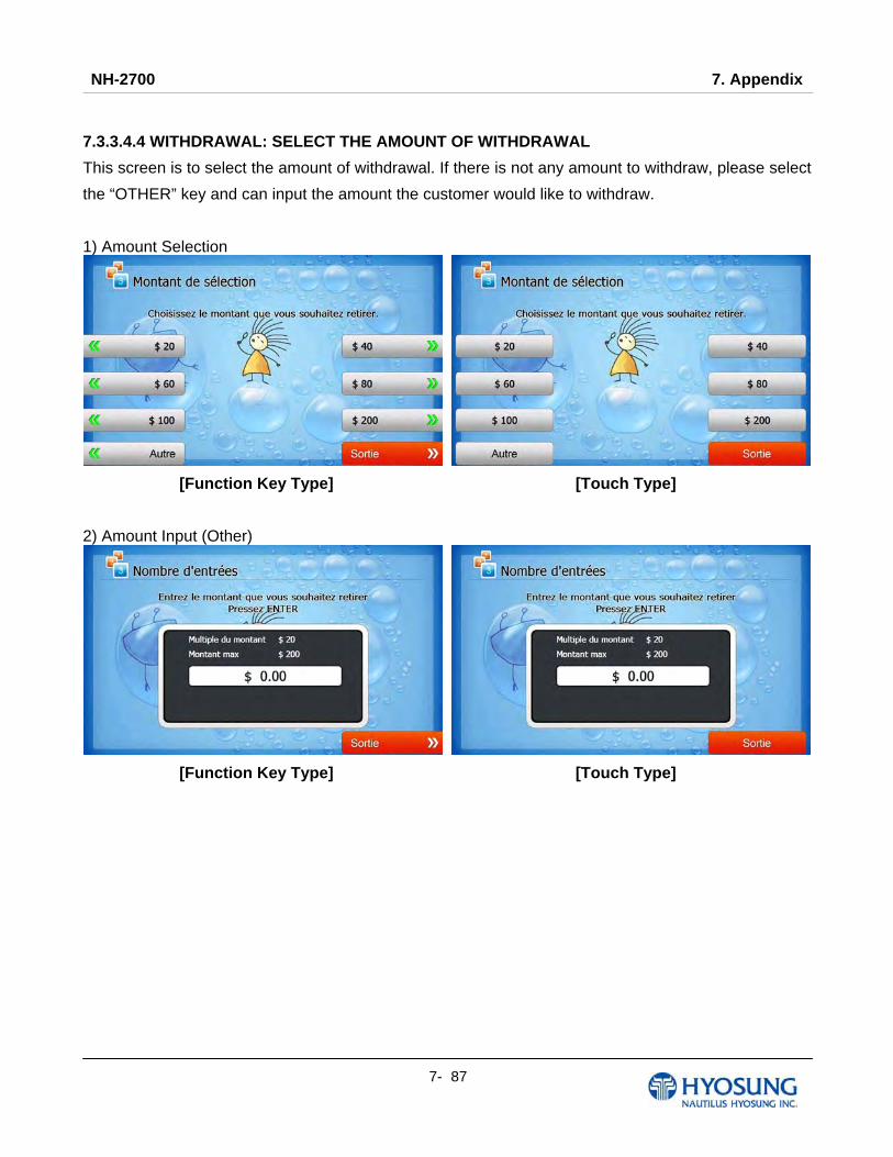
NH-2700 7. Appendix
7- 87
7.3.3.4.4 WITHDRAWAL: SELECT THE AMOUNT OF WITHDRAWAL
This screen is to select the amount of withdrawal. If there is not any amount to withdraw, please select
the “OTHER” key and can input the amount the customer would like to withdraw.
1) Amount Selection
[Function Key Type] [Touch Type]
2) Amount Input (Other)
[Function Key Type] [Touch Type]
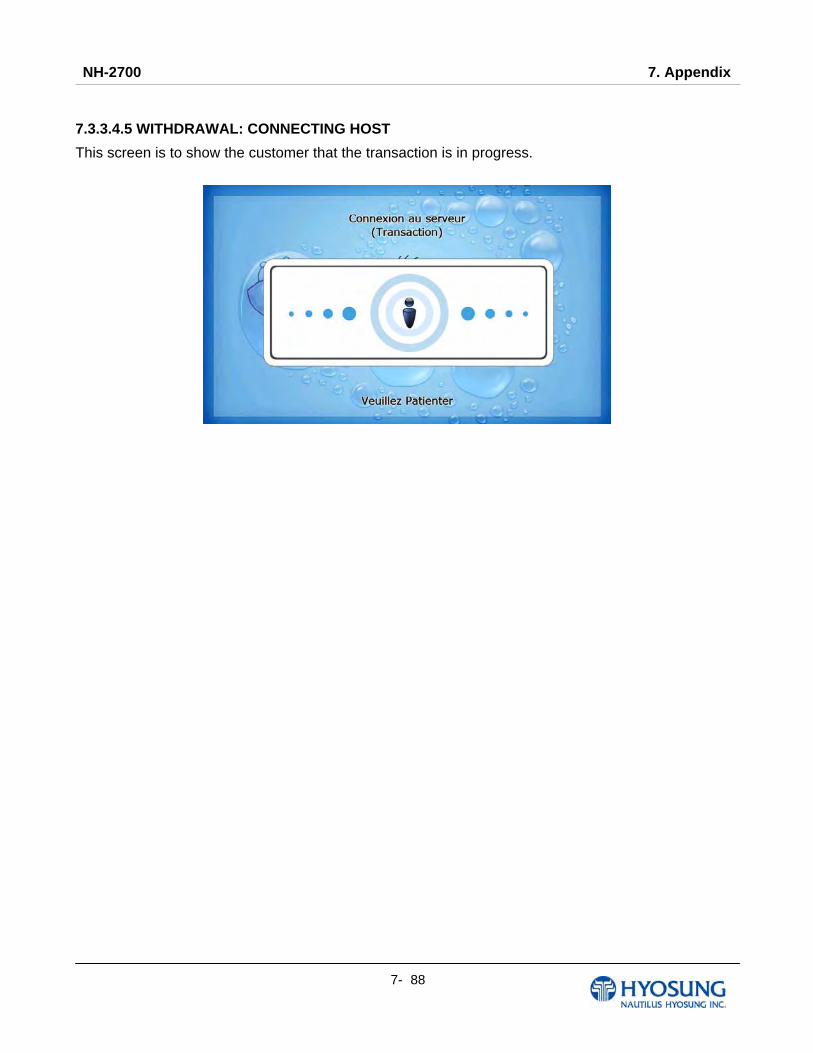
NH-2700 7. Appendix
7- 88
7.3.3.4.5 WITHDRAWAL: CONNECTING HOST
This screen is to show the customer that the transaction is in progress.

NH-2700 7. Appendix
7- 89
7.3.3.4.6 WITHDRAWAL: DISPENSING MONEY AND TAKE MONEY
This screen is to show the customer that his/her request amount is dispensing and to notify the
customer to take his/her money.
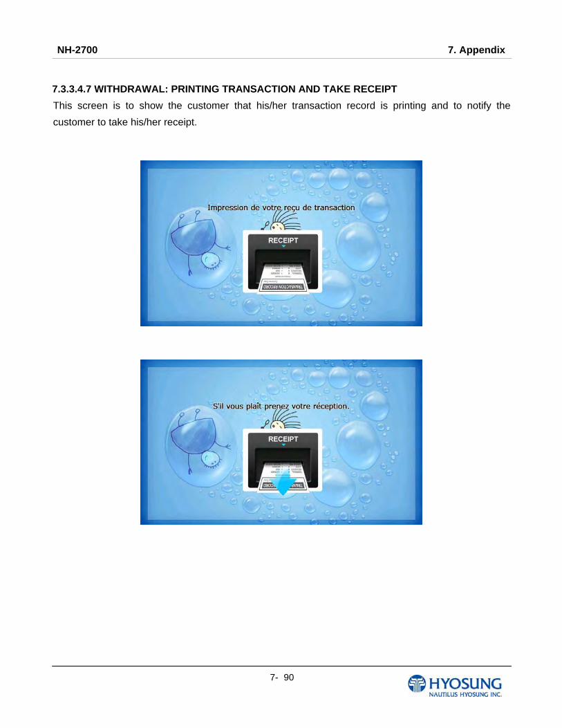
NH-2700 7. Appendix
7- 90
7.3.3.4.7 WITHDRAWAL: PRINTING TRANSACTION AND TAKE RECEIPT
This screen is to show the customer that his/her transaction record is printing and to notify the
customer to take his/her receipt.

NH-2700 7. Appendix
7- 91
7.3.3.4.8 WITHDRAWAL: THANK YOU
This screen is to show the customer that the transaction has been successfully completed.

NH-2700 7. Appendix
7- 92
7.3.3.4.9 TRANSFER: SELECT RECEIPT PRINTING OR NOT
This screen is to ask a customer if he/she gets the receipt or not.
[Function Key Type] [Touch Type]
7.3.3.4.10 TRANSFER: SELECT ACCOUNT TO TRANSFER FROM
This screen is to ask a customer where he/she wants to transfer from; checking, saving, credit card
[Function Key Type] [Touch Type]
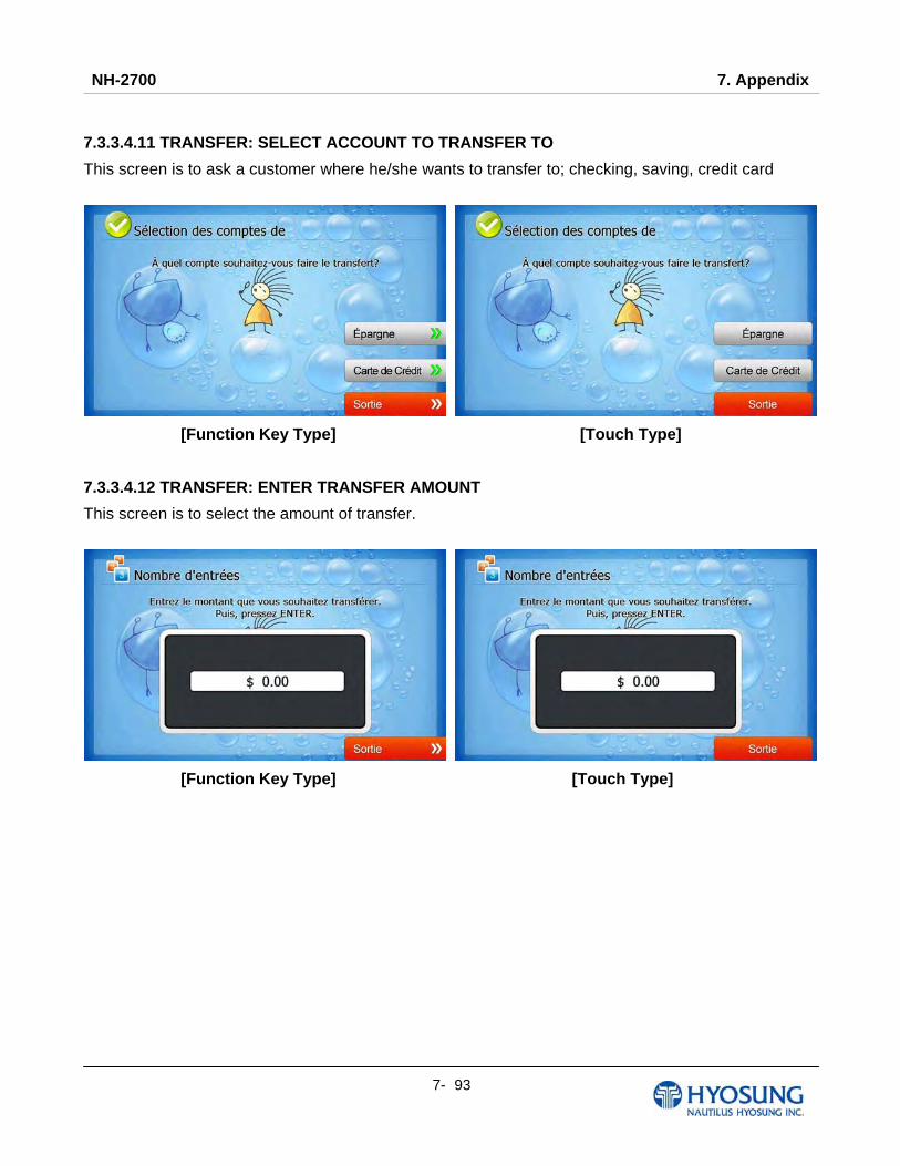
NH-2700 7. Appendix
7- 93
7.3.3.4.11 TRANSFER: SELECT ACCOUNT TO TRANSFER TO
This screen is to ask a customer where he/she wants to transfer to; checking, saving, credit card
[Function Key Type] [Touch Type]
7.3.3.4.12 TRANSFER: ENTER TRANSFER AMOUNT
This screen is to select the amount of transfer.
[Function Key Type] [Touch Type]

NH-2700 7. Appendix
7- 94
7.3.3.4.13 TRANSFER: CONNECTING HOST
This screen is to show the customer that the transaction is in progress.
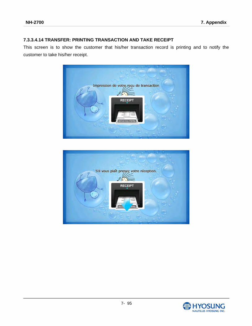
NH-2700 7. Appendix
7- 95
7.3.3.4.14 TRANSFER: PRINTING TRANSACTION AND TAKE RECEIPT
This screen is to show the customer that his/her transaction record is printing and to notify the
customer to take his/her receipt.

NH-2700 7. Appendix
7- 96
7.3.3.4.15 TRANSFER: THANK YOU
This screen is to show the customer that the transaction has been successfully completed.

NH-2700 7. Appendix
7- 97
7.3.3.4.16 INQUIRY: SELECT RECEIPT PRINTING OR NOT
This screen is to ask a customer if he/she wants to get the receipt or not.
[Function Key Type] [Touch Type]
7.3.3.4.17 INQUIRY: SELECT ACCOUNT TO INQUIRE
This screen is to ask a customer which account he/she wants to inquire
[Function Key Type] [Touch Type]

NH-2700 7. Appendix
7- 98
7.3.3.4.18 INQUIRY: CONNECTING HOST
This screen is to show the customer that the transaction is in progress.
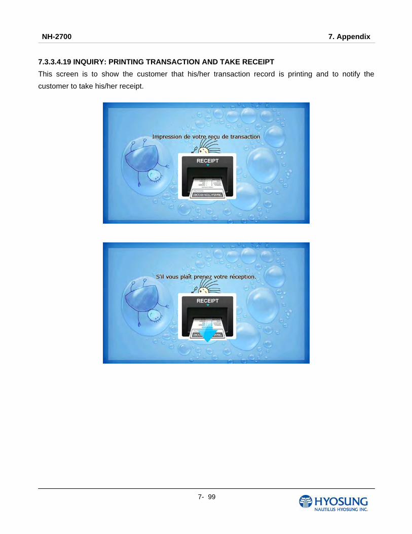
NH-2700 7. Appendix
7- 99
7.3.3.4.19 INQUIRY: PRINTING TRANSACTION AND TAKE RECEIPT
This screen is to show the customer that his/her transaction record is printing and to notify the
customer to take his/her receipt.
NH-2700 7. Appendix
7- 100
7.3.3.4.20 INQUIRY: THANK YOU
This screen is to show the customer that the transaction has been successfully completed.
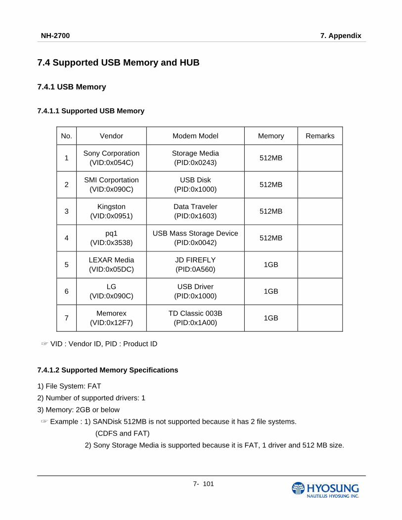
NH-2700 7. Appendix
7- 101
7.4 Supported USB Memory and HUB
7.4.1 USB Memory 7.4.1.1 Supported USB Memory
No. Vendor Modem Model Memory Remarks
1 Sony Corporation
(VID:0x054C) Storage Media (PID:0x0243)
512MB
2 SMI Corportation
(VID:0x090C) USB Disk
(PID:0x1000) 512MB
3 Kingston
(VID:0x0951) Data Traveler (PID:0x1603)
512MB
4 pq1
(VID:0x3538) USB Mass Storage Device
(PID:0x0042) 512MB
5 LEXAR Media (VID:0x05DC)
JD FIREFLY (PID:0A560)
1GB
6 LG
(VID:0x090C) USB Driver
(PID:0x1000) 1GB
7 Memorex
(VID:0x12F7) TD Classic 003B
(PID:0x1A00) 1GB
VID : Vendor ID, PID : Product ID☞
7.4.1.2 Supported Memory Specifications
1) File System: FAT
2) Number of supported drivers: 1
3) Memory: 2GB or below
☞ Example : 1) SANDisk 512MB is not supported because it has 2 file systems.
(CDFS and FAT)
2) Sony Storage Media is supported because it is FAT, 1 driver and 512 MB size.
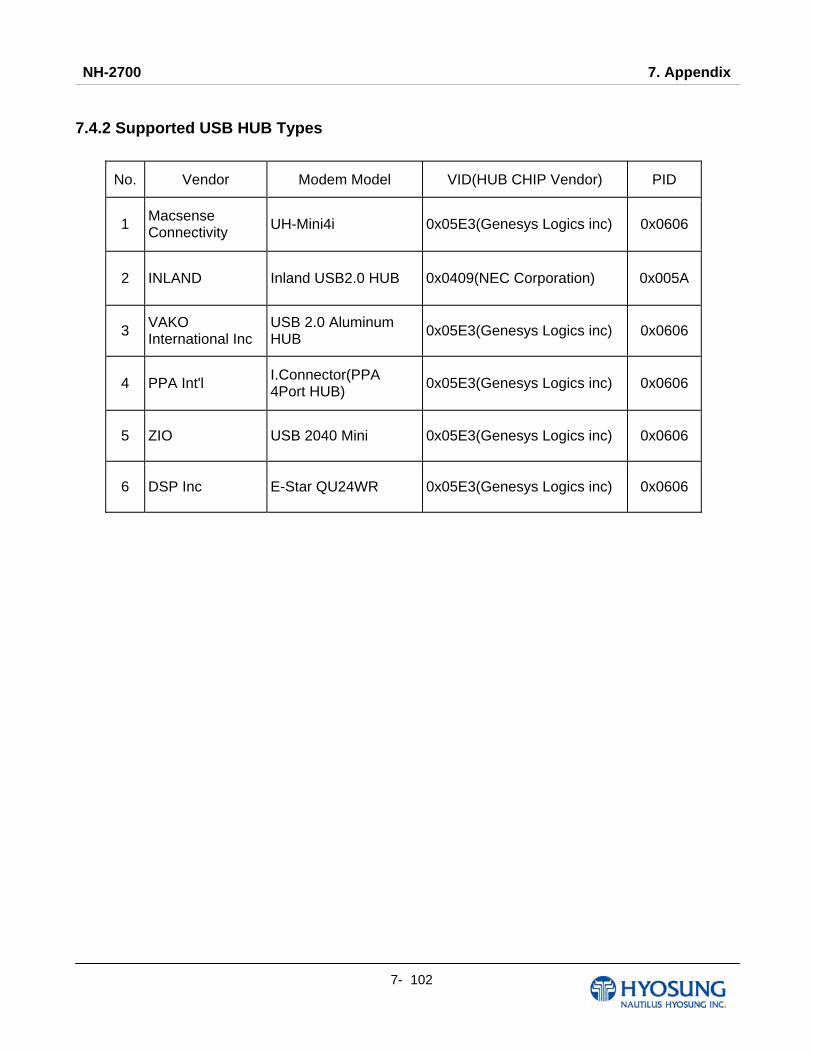
NH-2700 7. Appendix
7- 102
7.4.2 Supported USB HUB Types
No. Vendor Modem Model VID(HUB CHIP Vendor) PID
1 Macsense Connectivity UH-Mini4i 0x05E3(Genesys Logics inc) 0x0606
2 INLAND Inland USB2.0 HUB 0x0409(NEC Corporation) 0x005A
3 VAKO International Inc
USB 2.0 Aluminum HUB 0x05E3(Genesys Logics inc) 0x0606
4 PPA Int'l I.Connector(PPA 4Port HUB) 0x05E3(Genesys Logics inc) 0x0606
5 ZIO USB 2040 Mini 0x05E3(Genesys Logics inc) 0x0606
6 DSP Inc E-Star QU24WR 0x05E3(Genesys Logics inc) 0x0606

NH-2700 7. Appendix
7- 103
7.5 Advertisement Image Update Guide 7.5.1 Preparation
Software Update function in Nautilus Hyosung’s Windows CE Machine is applicable to update
advertisement images.
7.5.1.1 Supported Image Format
The following table describe the supporting format of welcome advertisement image
Model Image Size DPI Color File Format Max Size (one image)
NH-2700 1024 X 600 72 24bit color JPEG 300KB
The following table describe the supporting format of transaction advertisement image
Model Image Size DPI Color File Format Max Size (one image)
NH-2700 753 X 225 72 24bit color JPEG 160KB
The following table describe the file name and path of advertisement images. The path in blow table
indicates image size is 1024 X 600
Welcome Advertisement File Name Path
Screen #1 Adv_01.jpg \ATM\Advertisement\1024_600
Screen #2 Adv_02.jpg \ATM\Advertisement\1024_600
Screen #3 Adv_03.jpg \ATM\Advertisement\1024_600
Screen #4 Adv_04.jpg \ATM\Advertisement\1024_600
Screen #5 Adv_05.jpg \ATM\Advertisement\1024_600
Screen #6 Adv_06.jpg \ATM\Advertisement\1024_600
Transaction Advertisement File Name Path
Screen #1 TranAdv_01.jpg \ATM\Advertisement\1024_600
Screen #2 TranAdv_02.jpg \ATM\Advertisement\1024_600
Screen #3 TranAdv_03.jpg \ATM\Advertisement\1024_600
Screen #4 TranAdv_04.jpg \ATM\Advertisement\1024_600
Screen #5 TranAdv_05.jpg \ATM\Advertisement\1024_600
Screen #6 TranAdv_06.jpg \ATM\Advertisement\1024_600

NH-2700 7. Appendix
7- 104
7.5.1.2 Updating your own UpdateInfo.dat (Optional)
Advertisement images are updated using the software update program. While updating program
proceeds, a line of message shows up in the main screen. If you want to change the message, just
edit UpdateInfo.dat. The message length is up to 40 characters. A sample content is as follows.
You can replace “A sample message.(V1.21)” to your own message.
UpdateInfo.dat
A sample message. (V1.21)
NH-2700 7. Appendix
7- 105
7.5.1.3 Makeing SW Update media
1) Make “UPDATE” folder in the USB memory drive or the SD Card.
2) Make “NH2700CE” folder in the “UPDATE” folder.
3) Make “PATCH” folder in the “NH2700CE” folder.
4) Copy “UpdateInfo.dat” to under “PATCH” folder. (Optional)
5) Make “ADVERTISEMENT” folder in the “PATCH” folder.
6) Make “1024_600” folder in “ADVERTISEMENT” folder.
7) Copy all image files to under “1024_600” folder.(check the file name)
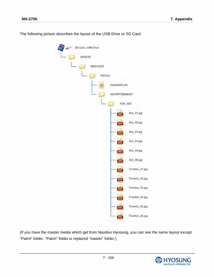
NH-2700 7. Appendix
7- 106
The following picture describes the layout of the USB Drive or SD Card.
(If you have the master media which get from Nautilus Hyosung, you can see the same layout except
“Patch” folder. “Patch” folder is replaced “master” folder.)
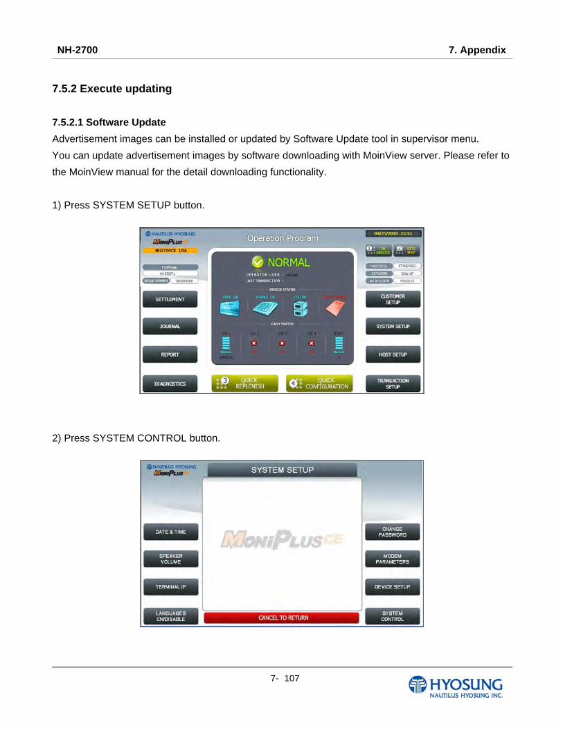
NH-2700 7. Appendix
7- 107
7.5.2 Execute updating
7.5.2.1 Software Update
Advertisement images can be installed or updated by Software Update tool in supervisor menu.
You can update advertisement images by software downloading with MoinView server. Please refer to
the MoinView manual for the detail downloading functionality.
1) Press SYSTEM SETUP button.
2) Press SYSTEM CONTROL button.
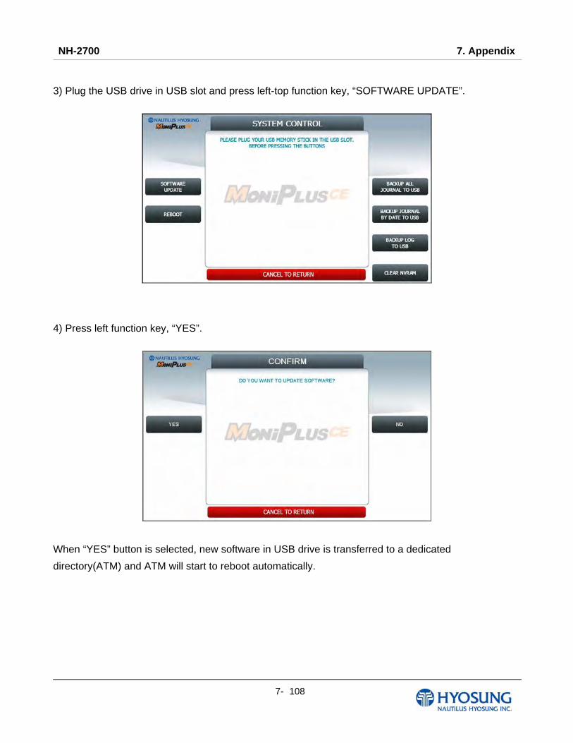
NH-2700 7. Appendix
7- 108
3) Plug the USB drive in USB slot and press left-top function key, “SOFTWARE UPDATE”.
4) Press left function key, “YES”.
When “YES” button is selected, new software in USB drive is transferred to a dedicated
directory(ATM) and ATM will start to reboot automatically.

NH-2700 7. Appendix
7- 109
7.5.2.2 Enable Welcome Advertisement
You can enable or disable Welcomoe Advertisement in the supervisor menu.
1) Press CUSTOMER SETUP button

NH-2700 7. Appendix
7- 110
2) Press “WELCOME ADVERTISEMENT” button
3) Press “WELCOME ADVERTISEMENT” button

NH-2700 7. Appendix
7- 111
4) You can enable or disable Advertisement images to view by pressing “SCREEN” Key.
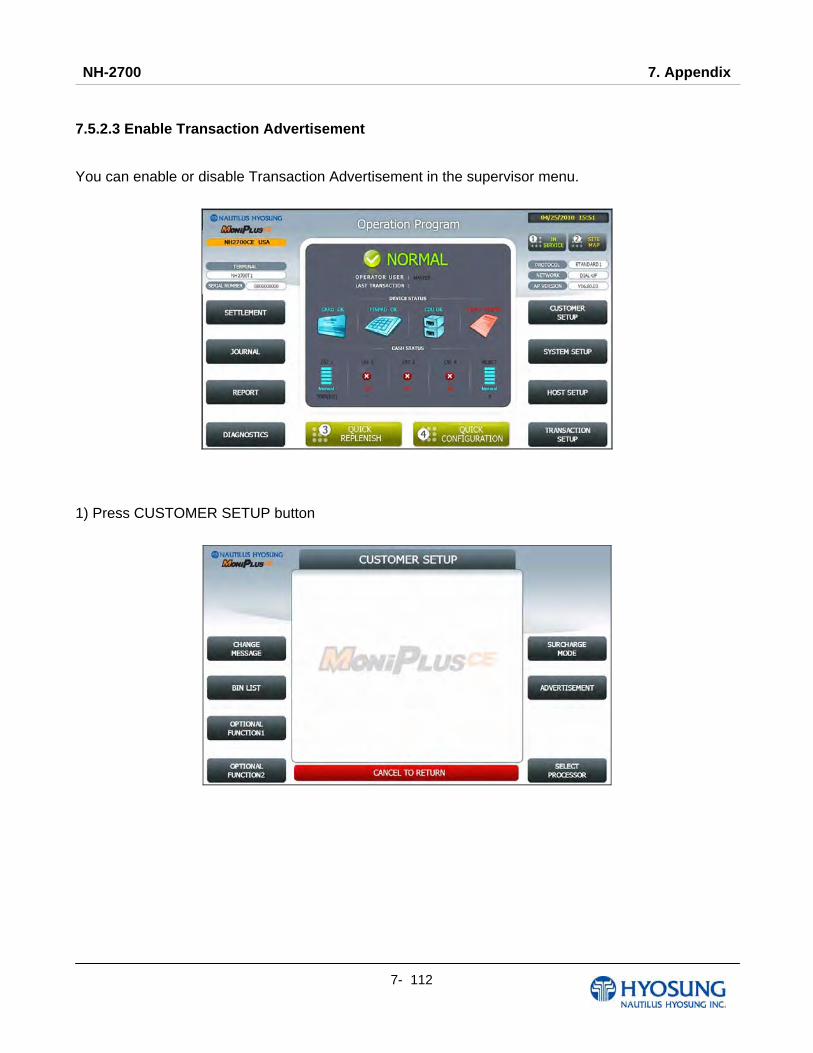
NH-2700 7. Appendix
7- 112
7.5.2.3 Enable Transaction Advertisement
You can enable or disable Transaction Advertisement in the supervisor menu.
1) Press CUSTOMER SETUP button
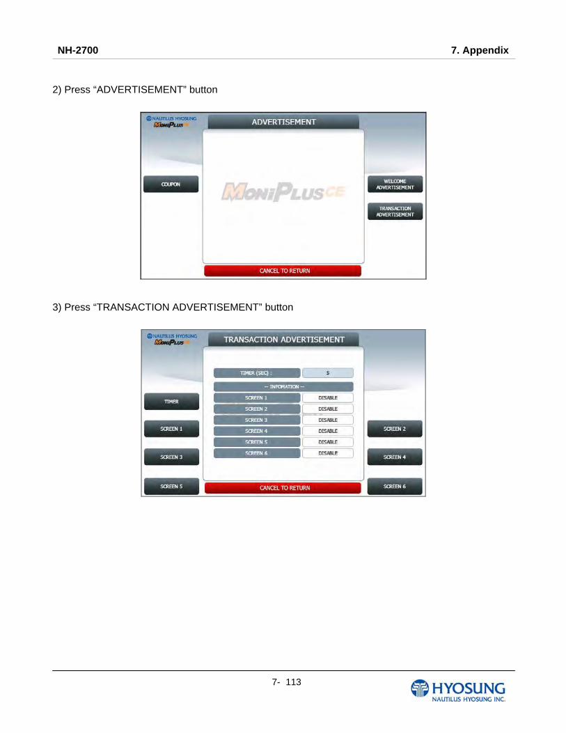
NH-2700 7. Appendix
7- 113
2) Press “ADVERTISEMENT” button
3) Press “TRANSACTION ADVERTISEMENT” button

NH-2700 7. Appendix
7- 114
4) You can enable or disable welcome dvertisement images to view by pressing “SCREEN” Key.
5) You can enable or disable transaction dvertisement images to view by pressing “SCREEN” Key.
NH-2700 7. Appendix
7- 115
7.5.3 Making MoniView update media
All supported image format refer to “Supported Image Format”
1) Make “PATCH” folder.
2) Copy “UpdateInfo.dat” to under “PATCH” folder. (Optional)
3) Make “ADVERTISEMENT” folder in the “PATCH” folder.
4) Make “1024_600” folder in “ADVERTISEMENT” folder.
5) Copy all image files to under “1024_600” folder.(check the file name)
6) Make comperessed file like the below layout.
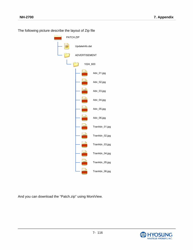
NH-2700 7. Appendix
7- 116
The following picture describe the layout of Zip file
UpdateInfo.dat
PATCH.ZIP
ADVERTISEMENT
1024_600
Adv_01.jpg
Adv_02.jpg
Adv_03.jpg
Adv_04.jpg
Adv_05.jpg
Adv_06.jpg
TranAdv_01.jpg
TranAdv_02.jpg
TranAdv_03.jpg
TranAdv_04.jpg
TranAdv_05.jpg
TranAdv_06.jpg
And you can download the “Patch.zip” using MoniView.
NH-2700 7. Appendix
7- 117
7.6 Background Image Update Guide 7.6.1 Preparation
Software Update function in Nautilus Hyosung’s Windows CE Machine is applicable to update
advertisement images.
7.6.1.1 Supported Image Format
The following table describe the supporting format of change background image
Model Image Size DPI Color File Format Max Size (one image)
NH-2700 1024 X 600 72 24bit color JPEG 300KB
The following table describe the file name and path of advertisement images. The path in blow table
indicates image size is 1024 X 600
Background File Name Path
Screen #1 Back_1.jpg \ATM\Screen\Backs\1024_600\Function (F/K)
\ATM\Screen\Backs\1024_600\Touch (Touch)
Screen #2 Back_2.jpg \ATM\Screen\Backs\1024_600\Function (F/K)
\ATM\Screen\Backs\1024_600\Touch (Touch)
Screen #3 Back_3.jpg \ATM\Screen\Backs\1024_600\Function (F/K)
\ATM\Screen\Backs\1024_600\Touch (Touch)
Screen #4 Back_4.jpg \ATM\Screen\Backs\1024_600\Function (F/K)
\ATM\Screen\Backs\1024_600\Touch (Touch)
Screen #5 Back_5.jpg \ATM\Screen\Backs\1024_600\Function (F/K)
\ATM\Screen\Backs\1024_600\Touch (Touch)
Screen #6 Back_6.jpg \ATM\Screen\Backs\1024_600\Function (F/K)
\ATM\Screen\Backs\1024_600\Touch (Touch)
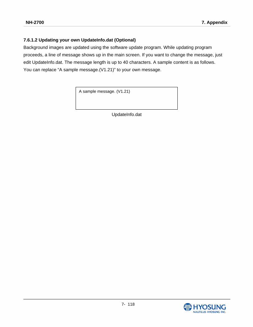
NH-2700 7. Appendix
7- 118
7.6.1.2 Updating your own UpdateInfo.dat (Optional)
Background images are updated using the software update program. While updating program
proceeds, a line of message shows up in the main screen. If you want to change the message, just
edit UpdateInfo.dat. The message length is up to 40 characters. A sample content is as follows.
You can replace “A sample message.(V1.21)” to your own message.
UpdateInfo.dat
A sample message. (V1.21)
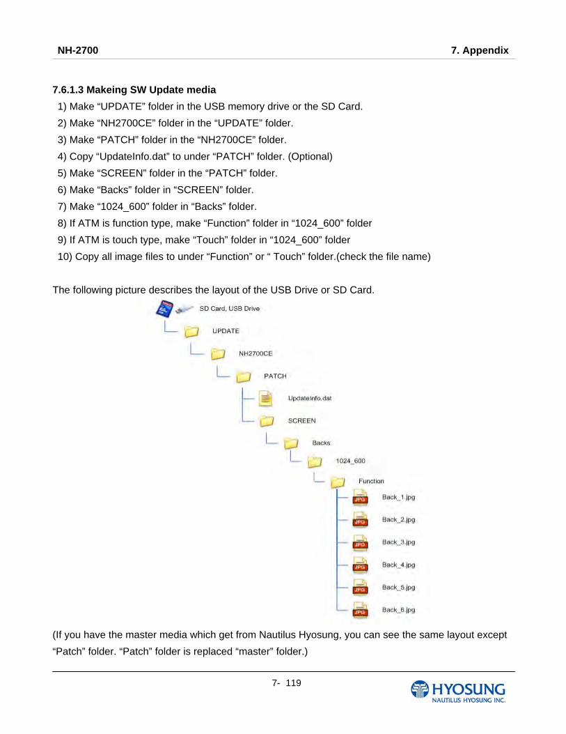
NH-2700 7. Appendix
7- 119
7.6.1.3 Makeing SW Update media
1) Make “UPDATE” folder in the USB memory drive or the SD Card.
2) Make “NH2700CE” folder in the “UPDATE” folder.
3) Make “PATCH” folder in the “NH2700CE” folder.
4) Copy “UpdateInfo.dat” to under “PATCH” folder. (Optional)
5) Make “SCREEN” folder in the “PATCH” folder.
6) Make “Backs” folder in “SCREEN” folder.
7) Make “1024_600” folder in “Backs” folder.
8) If ATM is function type, make “Function” folder in “1024_600” folder
9) If ATM is touch type, make “Touch” folder in “1024_600” folder
10) Copy all image files to under “Function” or “ Touch” folder.(check the file name)
The following picture describes the layout of the USB Drive or SD Card.
(If you have the master media which get from Nautilus Hyosung, you can see the same layout except
“Patch” folder. “Patch” folder is replaced “master” folder.)

NH-2700 7. Appendix
7- 120
7.6.2 Execute updating
7.6.2.1 Software Update
Advertisement images can be installed or updated by Software Update tool in supervisor menu.
You can update advertisement images by software downloading with MoinView server. Please refer to
the MoinView manual for the detail downloading functionality.
1) Press SYSTEM SETUP button.
2) Press SYSTEM CONTROL button.

NH-2700 7. Appendix
7- 121
3) Plug the USB drive in USB slot and press left-top function key, “SOFTWARE UPDATE”.
4) Press left function key, “YES”.
When “YES” button is selected, new software in USB drive is transferred to a dedicated
directory(ATM) and ATM will start to reboot automatically.

NH-2700 7. Appendix
7- 122
7.6.2.2 Setup change background
You can set up change background option in the supervisor menu.
1) Press CUSTOMER SETUP button
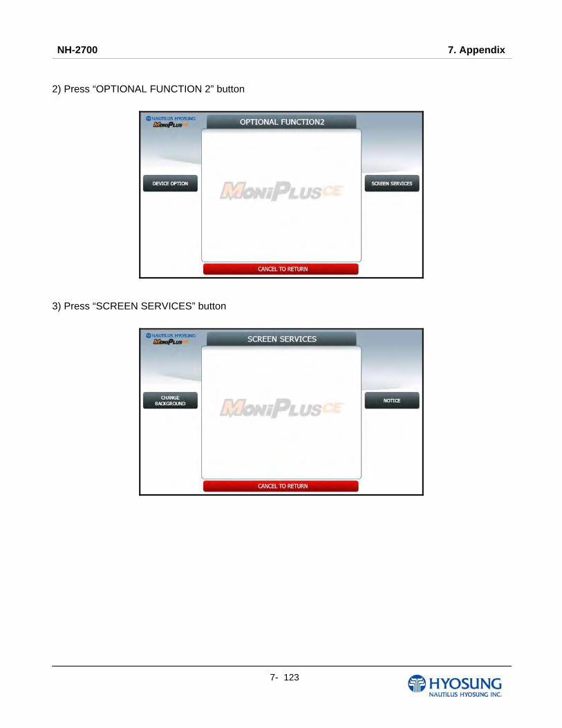
NH-2700 7. Appendix
7- 123
2) Press “OPTIONAL FUNCTION 2” button
3) Press “SCREEN SERVICES” button
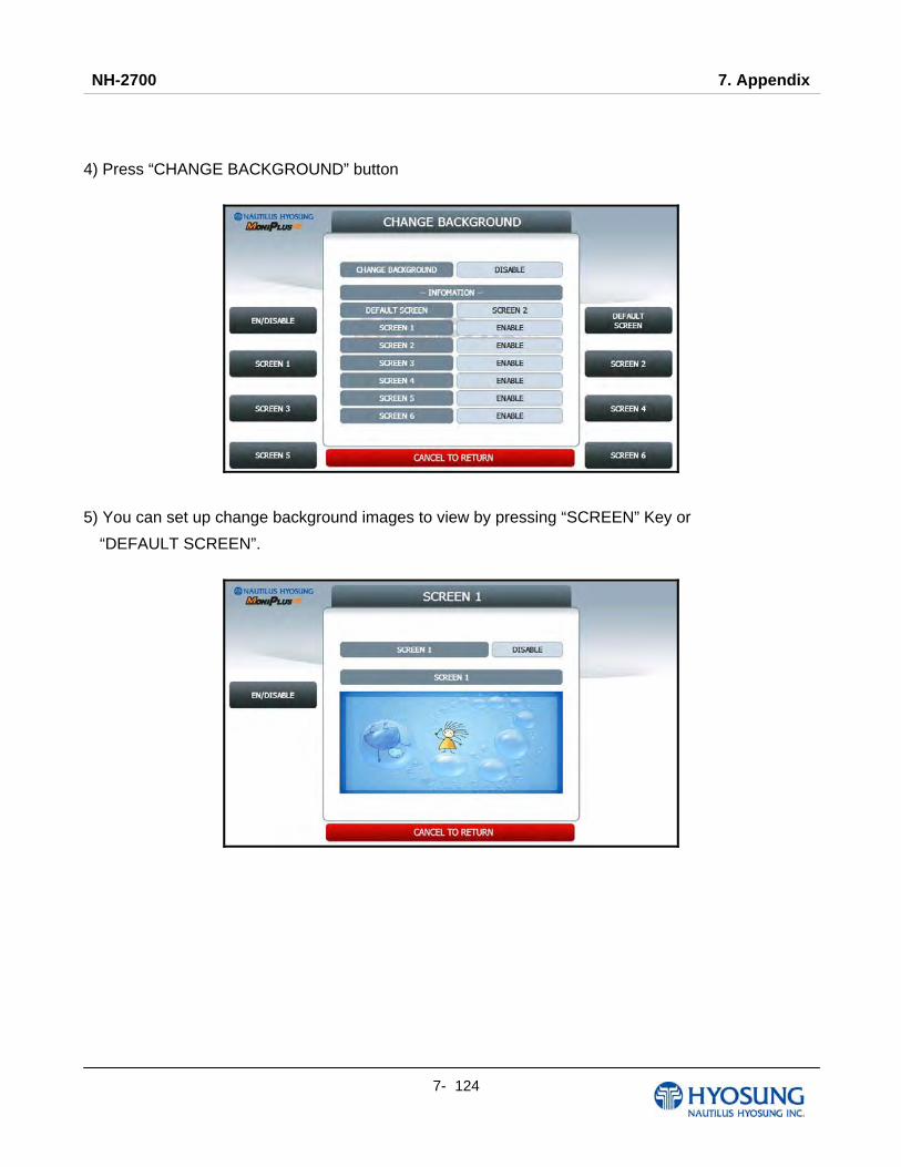
NH-2700 7. Appendix
7- 124
4) Press “CHANGE BACKGROUND” button
5) You can set up change background images to view by pressing “SCREEN” Key or
“DEFAULT SCREEN”.

NH-2700 7. Appendix
7- 125
7.6.3 Making MoniView update media
All supported image format refer to “Supported Image Format”
1) Make “PATCH” folder.
2) Copy “UpdateInfo.dat” to under “PATCH” folder. (Optional)
3) Make “SCREEN” folder in the “PATCH” folder.
4) Make “Backs” folder in “SCREEN” folder.
5) Make “1024_600” folder in “Backs” folder.
6) If ATM is function type, make “Function” folder in “1024_600” folder
7) If ATM is touch type, make “Touch” folder in “1024_600” folder
8) Copy all image files to under “Function” or “ Touch” folder.(check the file name)
9) Make comperessed file like the below layout.
The following picture describe the layout of Zip file
UpdateInfo.dat
SCREEN
1024_600
JPG Back_1.jpg
JPG Back_2.jpg
JPG Back_3.jpg
JPG Back_4.jpg
JPG Back_5.jpg
JPG Back_6.jpg
Backs
Function
PATCH.ZIPZIP
And you can download the “Patch.zip” using MoniView.
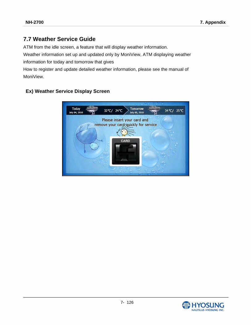
NH-2700 7. Appendix
7- 126
7.7 Weather Service Guide
ATM from the idle screen, a feature that will display weather information.
Weather information set up and updated only by MoniView, ATM displaying weather
information for today and tomorrow that gives
How to register and update detailed weather information, please see the manual of
MoniView.
Ex) Weather Service Display Screen