ngf optical distribution frame - commscope.com optical distribution frame 3 frame commscope’s next...
TRANSCRIPT

NGF optical distribution frame

2 NGF optical distribution frame
Contents
Introduction 3
Product overview 3
Things to consider when ordering 4
Frame capacity requirements (important facts on trough space) 4
Frame lineup capacity comparisons 4
NGF frame considerations 4
Block and frame termination capacity 4
Zoning recommendations (by vertical) 5
Zoning recommendations (by frame) 5
Fiber main distributing frame 6
Front facing fiber main distributing frame 7
Preterminated fiber termination blocks with multifiber cable—IFC 8
Preterminated fiber termination blocks with MPO connectors 10
Adapter-only fiber termination blocks 11
Adapter-only fiber termination blocks—conversion kits 12
Cable clamping kit and block conversion kit 12
Value-added module (VAM) microVAM chassis 12
Frame accessories 13
Fiber optic terminal jumper storage panel 13
Fiber optic terminal jumper storage panel zoning recommendations 14
Fiber optic terminal jumper storage panel 14
Equipment frame 14
End guard 14
Frame extender 14
Grounding kit 15
Isolation pad 15
Frame installation kit 15
Cable clamp kit 15
Standard cross-connect patch cord lengths 16

NGF optical distribution frame 3
Frame
CommScope’s next generation frame (NGF) product line has fiber
frames designed to fit a variety of network applications. Each frame
option is designed with an emphasis on superior cable management
and ease of use, including features such as ample trough space
for cable and jumpers, easy access to connectors and storage for
jumpers. The frame sections are shipped from the factory fully
equipped with all cable management hardware including integrated
jumper slack storage.
Fiber termination block (FTB)
CommScope’s FTB is available with industry-standard adapters
in block configurations of 72-, 96- and 144- positions. Also, a
192-position FTB is available using LC adapters. FTBs utilize sliding
adapter packs to gain easy access to both the front and rear
terminations. To accommodate varying network requirements
and speed installation, FTBs can be ordered with adapters only or
preterminated with either intrafacility cable (IFC) or outside plant
(OSP) cables.
Introduction
Value-added module block (VAM)
Adding signal management and enhancement functions, such as
splitters, couplers and wavelength division multiplexers, optimizes
the value of your fiber network, by providing nonintrusive access to
the optical signal for monitoring and testing signal integrity. There is
a block configuration available to accommodate Micro Value-Added
Modules (MicroVAMs) for applications requiring splitters or WDMs.
Fiber optic terminal storage panel
CommScope’s fiber optic terminal storage panel is used as a storage
apparatus for up to 16 feet of equipment (FOT) jumpers at the fiber
frame lineup. This panel can be installed between fiber frames and at
the end of a lineup.
Product overview
Recommended applications Medium to large fiber count applications or any space constrained applications. Highest fiber count solution available.
Description High-density solution using 72-, 96-, 144- and 192-position blocks (FTB)
Number of fibers, future growth potential
Up to 29,177 in 17 frames using 144-position blocks, SC connectors and 1.7 mm patch cords
Up to 32,939 in 15 frames using 192-position blocks, LC connectors and 1.7 mm patch cords
Interconnect Good
Cross-connect Excellent
Accommodates on-frame splicing Good
Accommodates off-frame splicing Excellent
Density – terminations per frame1,728 terminations using standard connectors;
2,304 terminations using LC connectors
Front access to rear connector Yes
VAM capabilities Yes. Separate panel required
Slack storage location On-frame (integrated jumper slack storage)
Connector access Sliding adapter pack

4 NGF optical distribution frame
Frame capacity requirements (important facts on trough space)
144 FTB(1,728/frame)
96 FTB(1,152/frame)
72 FTB(864/frame)
NGF 12 frames 18 frames 24 frames
Front-facing NGF 4 frames 6 frames 8 frames
Calculation assumptions:
· Per Telecordia® GR-449-CORE, Issue 2 requirements
· 2.0 mm jumpers (maximum recommended diameter for all NGF products)
· 2" maximum jumper pile
· 50% of jumpers do not appear at any given place in lineup (50% rule)
Frame lineup capacity comparisons
2.0 mm jumpers/maximum recommended diameter for NGF products
NGF frame:1,728 Fiber
terminations
Conventional frame:
1,152 Fiber terminations
Conventional frame:
648 Fiber terminations
Horizontal trough space 30" 10" (5" upper
and lower) 5" Lower
Maximum number of
terminations allowed
in a frame lineup before exceeding 2”
pileup
21,081 8,240 4,120
NGF frame considerations
NGF frameFront-facing NGF frame Slim rack
Flexibility/ability to
grow frame lineup
Yes Yes No
Interconnect Supports Supports Supports
Cross-connect Supports Supports Supports
On-frame splicing Supports Supports Supports
Off-frame splicing Supports Supports Supports
Rear access required Yes No No
All front access No Yes Yes
Footprint 30" Wide x 24" Deep
30" Wide x 19" Deep
19" Wide x 19" Deep
Horizontal trough space
available30" 9" N/A
Block and frame termination capacity
NGF block termination capacity NGF frame termination capacity
72 864
96 1,152
144 1,728
192 (LC connectors only) 2,304
Things to consider when ordering

NGF optical distribution frame 5
Zoning recommendations (by vertical) Zoning recommendations (by frame)
5/
07
•
1
03
74
2A
E
O
pti
cal
Dis
trib
uti
on
Fra
mes
8w w w . a d c . c o m • + 1 - 9 5 2 - 9 3 8 - 8 0 8 0 • 1 - 8 0 0 - 3 6 6 - 3 8 9 1
Hig
h-D
ensi
ty F
ram
e So
luti
on
s
Zoning Recommendations (by Frame)
NGF Optical Distribution FrameThings to Consider When Ordering
IFC Cable
EQT Cable
Cross-Connect Jumper
KeyOSP -EQT -FOTSP - FGS -NGF -
OSP Frame EQT Frame OSP Frame
FGS
FOTSP-SLNGF Frame 1 NGF Frame 2 NGF Frame 3FOTSP-SR
(30")762 mm
Outside PlantEquipmentFiber Optic TerminalStorage PanelFiberGuide SystemNext Generation Frame
(8")2.95 m
203 mm
(116")
2.14 m(7')
OSP Frame EQT Frame OSP Frame
FGS
EQT Frame
IFC Cable
EQT Cable
Cross-Connect Jumper
KeyOSP -EQT -FOTSP - FGS -NGF -
FOTSP-SLNGF Frame 1 NGF Frame 2 NGF Frame 3 NGF Frame 4FOTSP-SR FOTSP-SL FOTSP-SR
(30")762 mm
Outside PlantEquipmentFiber Optic TerminalStorage PanelFiberGuide SystemNext Generation Frame
(8")
2.14 m(7')
203 mm
(162")4.1 m
Cross-Connect Application using 8-inch wide FOTSP in a 2:1 Application(2 Equipment to 1 OSP)
Cross-Connect Application using 8-inch wide FOTSP in a 1:1 Application(1 Equipment to 1 OSP)
5/
07
•
1
03
74
2A
E
O
pti
cal
Dis
trib
uti
on
Fra
mes
8w w w . a d c . c o m • + 1 - 9 5 2 - 9 3 8 - 8 0 8 0 • 1 - 8 0 0 - 3 6 6 - 3 8 9 1
Hig
h-D
en
sit
y F
ram
e S
olu
tio
ns
Zoning Recommendations (by Frame)
NGF Optical Distribution FrameThings to Consider When Ordering
IFC Cable
EQT Cable
Cross-Connect Jumper
KeyOSP -EQT -FOTSP - FGS -NGF -
OSP Frame EQT Frame OSP Frame
FGS
FOTSP-SLNGF Frame 1 NGF Frame 2 NGF Frame 3FOTSP-SR
(30")762 mm
Outside PlantEquipmentFiber Optic TerminalStorage PanelFiberGuide SystemNext Generation Frame
(8")2.95 m
203 mm
(116")
2.14 m(7')
OSP Frame EQT Frame OSP Frame
FGS
EQT Frame
IFC Cable
EQT Cable
Cross-Connect Jumper
KeyOSP -EQT -FOTSP - FGS -NGF -
FOTSP-SLNGF Frame 1 NGF Frame 2 NGF Frame 3 NGF Frame 4FOTSP-SR FOTSP-SL FOTSP-SR
(30")762 mm
Outside PlantEquipmentFiber Optic TerminalStorage PanelFiberGuide SystemNext Generation Frame
(8")
2.14 m(7')
203 mm
(162")4.1 m
Cross-Connect Application using 8-inch wide FOTSP in a 2:1 Application(2 Equipment to 1 OSP)
Cross-Connect Application using 8-inch wide FOTSP in a 1:1 Application(1 Equipment to 1 OSP)Cross-connect application using 8-inch wide FOTSP in a 1:1 application
(1 Equipment to 1 OSP)
Cross-connect application using 8-inch wide FOTSP in a 2:1 application(2 Equipment to 1 OSP)
5/
07
•
1
03
74
2A
E
O
pti
cal
Dis
trib
uti
on
Fra
mes
7w w w . a d c . c o m • + 1 - 9 5 2 - 9 3 8 - 8 0 8 0 • 1 - 8 0 0 - 3 6 6 - 3 8 9 1
Hig
h-D
ensi
ty F
ram
e So
luti
on
s
Zoning Recommendations (by Vertical)
IFC Cable
EQT Cable
Cross-Connect Jumper
KeyTELCO -EQT -FOTSP -
FGS - NGF -
FGS
FOTSP FOTSPOSP EQT EQT EQT OSPEQT
FOTSP FOTSPNGF Frame 1 NGF Frame 2 NGF Frame 3
TelcoEquipmentFiber Optic TerminalStorage PanelFiberGuide SystemNext Generation Frame
762 mm(30") 305 mm
(12")3.13 m(10.3')
2.14 m(7')
FOTSP FOTSP
OSP
IFC Cable
EQT Cable
Cross-Connect Jumper
KeyOSP - EQT - FOTSP - FGS - NGF -
EQT EQT OSP EQT
NGF Frame 1 NGF Frame 2 NGF Frame 3
FGS
OSP
Outside PlantEquipmentFiber Optic TerminalStorage PanelFiberGuide SystemNext Generation Frame
762 mm(30")
305 mm(12")3.13 m
(10.3')
2.14 m(7')
NGF Optical Distribution FrameThings to Consider When Ordering
Cross-Connect Application using 12-inch wide FOTSP in a 2:1 Application(2 Equipment to 1 OSP)
Cross-Connect Application using 12-inch wide FOTSP in a 1:1 Application(1 Equipment to 1 OSP)
Cross-connect application using 12-inch wide FOTSP in a 2:1 application(2 Equipment to 1 OSP)
Cross-connect application using 12-inch wide FOTSP in a 1:1 application(1 Equipment to 1 OSP)
5/
07
•
1
03
74
2A
E
O
pti
cal
Dis
trib
uti
on
Fra
mes
8w w w . a d c . c o m • + 1 - 9 5 2 - 9 3 8 - 8 0 8 0 • 1 - 8 0 0 - 3 6 6 - 3 8 9 1
Hig
h-D
ensi
ty F
ram
e So
luti
on
s
Zoning Recommendations (by Frame)
NGF Optical Distribution FrameThings to Consider When Ordering
IFC Cable
EQT Cable
Cross-Connect Jumper
KeyOSP -EQT -FOTSP - FGS -NGF -
OSP Frame EQT Frame OSP Frame
FGS
FOTSP-SLNGF Frame 1 NGF Frame 2 NGF Frame 3FOTSP-SR
(30")762 mm
Outside PlantEquipmentFiber Optic TerminalStorage PanelFiberGuide SystemNext Generation Frame
(8")2.95 m
203 mm
(116")
2.14 m(7')
OSP Frame EQT Frame OSP Frame
FGS
EQT Frame
IFC Cable
EQT Cable
Cross-Connect Jumper
KeyOSP -EQT -FOTSP - FGS -NGF -
FOTSP-SLNGF Frame 1 NGF Frame 2 NGF Frame 3 NGF Frame 4FOTSP-SR FOTSP-SL FOTSP-SR
(30")762 mm
Outside PlantEquipmentFiber Optic TerminalStorage PanelFiberGuide SystemNext Generation Frame
(8")
2.14 m(7')
203 mm
(162")4.1 m
Cross-Connect Application using 8-inch wide FOTSP in a 2:1 Application(2 Equipment to 1 OSP)
Cross-Connect Application using 8-inch wide FOTSP in a 1:1 Application(1 Equipment to 1 OSP)

6 NGF optical distribution frame
Fiber main distributing frameThe zone 4 rated fiber main distributing frame (FMDF) is the cornerstone of the NGF product line. The footprint of the frame is
GR-449-CORE, Issue 2 compliant. This innovative frame has six 5-inch horizontal troughs for a total of 30 inches of horizontal
trough space. This abundant trough space minimizes fiber pile up and congestion leading to easier jumper traceability and removal.
The frame has 12 fiber termination block (FTB) mounting positions equally divided between vertical columns on the left and right
sides of the frame as shown in the figure below. The frame provides sufficient vertical trough space for the highest termination
density applications and includes built-in jumper storage that will store up to 3.5 meters of jumper slack. The NGF is designed such
that only a single jumper length (6 meters) is required to go between any two termination points within a frame.
Ordering information
Description Dimensions (HxWxD) Maximum termination capacity Catalog number
NGF fiber maindistributing frame
2.14 m x 762 mm x 610 mm(7' x 30" x 24")
1,728(2,304 using LC connectors) NGF-MDF7A100-30
Each frame section includes heavy duty floor anchor bolts for concrete floor applications.
5/
07
•
1
03
74
2A
E
O
pti
cal
Dis
trib
uti
on
Fra
mes
10w w w . a d c . c o m • + 1 - 9 5 2 - 9 3 8 - 8 0 8 0 • 1 - 8 0 0 - 3 6 6 - 3 8 9 1
Hig
h-D
ensi
ty F
ram
e So
luti
on
s
NGF Optical Distribution FrameFiber Main Distributing Frame
JumperStorage
Panel
LeftVertical
RightVertical
FTBMounting
Position(12)
2.14 m(7')
610 mm (24")
Front ISO View Front View Side View
Each frame section includes heavy duty floor anchor bolts for concrete floor applications. See page 30 for additional mounting options.
The zone 4 rated fiber main distributing frame (FMDF) is the cornerstone of the NGF product line. The footprint of the frame is GR-449-CORE, Issue 2 compliant. This innovative frame has six 5-inch horizontal troughs for a total of 30 inches of horizontal trough space. This abundant trough space minimizes fiber pile up and congestion leading to easier jumper traceability and removal. The frame has 12 fiber termination block (FTB) mounting positions equally divided between vertical columns on the left and right sides of the frame as shown in the figure below. The frame provides sufficient vertical trough space for the highest termination density applications and includes built-in jumper storage that will store up to 3.5 meters of jumper slack. The NGF is designed such that only a single jumper length (6 meters) is required to go between any two termination points within a frame.
RearHorizontalTrough(6)
Description Dimensions (HxWxD)Maximum
Termination Capacity Catalog Number
NGF fiber main distributing frame
2.14 m x 762 mm x 610 mm (7' x 30" x 24")
1,728(2,304 using LC connectors)
NGF-MDF7A100-30
O r d e r i n g I n f o r m a t i o n
762 mm (30")
Front ISO view Front view Side view
NGF optical distribution frame 7
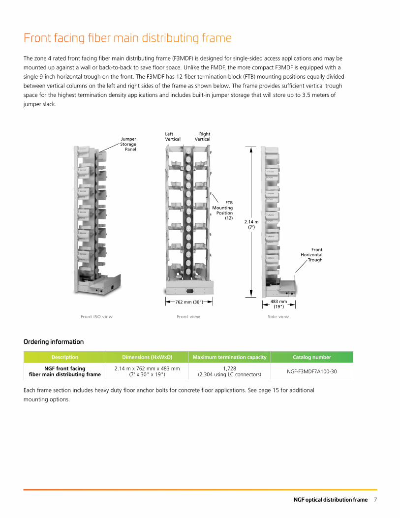
Front facing fiber main distributing frameThe zone 4 rated front facing fiber main distributing frame (F3MDF) is designed for single-sided access applications and may be
mounted up against a wall or back-to-back to save floor space. Unlike the FMDF, the more compact F3MDF is equipped with a
single 9-inch horizontal trough on the front. The F3MDF has 12 fiber termination block (FTB) mounting positions equally divided
between vertical columns on the left and right sides of the frame as shown below. The frame provides sufficient vertical trough
space for the highest termination density applications and includes built-in jumper storage that will store up to 3.5 meters of
jumper slack.
Ordering information
Description Dimensions (HxWxD) Maximum termination capacity Catalog number
NGF front facingfiber main distributing frame
2.14 m x 762 mm x 483 mm(7' x 30" x 19")
1,728(2,304 using LC connectors) NGF-F3MDF7A100-30
Each frame section includes heavy duty floor anchor bolts for concrete floor applications. See page 15 for additional
mounting options.
5/
07
•
1
03
74
2A
E
O
pti
cal
Dis
trib
uti
on
Fra
mes
11w w w . a d c . c o m • + 1 - 9 5 2 - 9 3 8 - 8 0 8 0 • 1 - 8 0 0 - 3 6 6 - 3 8 9 1
Hig
h-D
ensi
ty F
ram
e So
luti
on
s
NGF Optical Distribution FrameFront Facing Fiber Main Distributing Frame
JumperStorage
Panel
2.14 m(7')
762 mm (30") 483 mm(19")
Front ISO View Front View Side View
Each frame section includes heavy duty floor anchor bolts for concrete floor applications. See page 30 for additional mounting options.
O r d e r i n g I n f o r m a t i o n
The zone 4 rated front facing fiber main distributing frame (F3MDF) is designed for single-sided access applications and may be mounted up against a wall or back-to-back to save floor space. Unlike the FMDF, the more compact F3MDF is equipped with a single 9-inch horizontal trough on the front. The F3MDF has 12 fiber termination block (FTB) mounting positions equally divided between vertical columns on the left and right sides of the frame as shown below. The frame provides sufficient vertical trough space for the highest termination density applications and includes built-in jumper storage that will store up to 3.5 meters of jumper slack.
LeftVertical
RightVertical
FTBMounting
Position(12)
Description Dimensions (HxWxD)Maximum
Termination Capacity Catalog Number
NGF front facing fiber main distributing frame
2.14 m x 762 mm x 483 mm (7' x 30" x 19")
1,728(2,304 using LC connectors)
NGF-F3MDF7A100-30
FrontHorizontal
Trough
Front ISO view Front view Side view

8 NGF optical distribution frame
Preterminated fiber termination blocks (FTBs) are available with either
indoor or outdoor rated cable in ribbon or stranded configurations. All
blocks are 100% factory tested to guarantee continuity and reliable
connections. Preterminated FTBs make installation quick and easy,
reducing labor costs. Before ordering, determine the block orientation
and cable exit direction. Preterminated FTBs may be ordered with a
“left” orientation (mounts on the left side of the frame) or a “right”
orientation (mounts on the right side of the frame). The cable exit
direction will be either “upward” (cables terminated to the rear side of
the block exit up toward the top of the frame) or “downward” (cables
terminated to the rear side of the block exit down toward the bottom
of the frame).
Definition of variables
1 Block typeGeneral adapter type required in the FTB
2 Block capacityMaximum number of terminations that the FTB will accommodate when fully loaded
3 Block orientationVertical column of the frame the FTB is to be mounted on
4 Cable exit directionDirection the equipment jumpers or OSP cable will exit from the FTB
5 Connector and adapter type #1Specific adapter/connector type required at the FTB
6 Connector type #2Specific connector type required at the far end opposite the FTB
7Cable type
Type of cable to be terminated to the FTB
8 Cable lengthRequired length of the cable terminated to the FTB
Ordering information follows on next page.
5/
07
•
1
03
74
2A
E
O
pti
cal
Dis
trib
uti
on
Fra
mes
13w w w . a d c . c o m • + 1 - 9 5 2 - 9 3 8 - 8 0 8 0 • 1 - 8 0 0 - 3 6 6 - 3 8 9 1
Hig
h-D
ensi
ty F
ram
e So
luti
on
s
NGF Optical Distribution FramePreterminated Fiber Termination Blocks with Multifiber Cable – IFC
Preterminated fiber termination blocks (FTBs) are available with either indoor or outdoor rated cable in ribbon or stranded configurations. All blocks are 100% factory tested to guarantee continuity and reliable connections. Preterminated FTBs make installation quick and easy, reducing labor costs. Before ordering, determine the block orientation and cable exit direction. Preterminated FTBs may be ordered with a “left” orientation (mounts on the left side of the frame) or a “right” orientation (mounts on the right side of the frame). The cable exit direction will be either “upward” (cables terminated to the rear side of the block exit up toward the top of the frame) or “downward” (cables terminated to the rear side of the block exit down toward the bottom of the frame).
Ordering information follows on next page.
Block TypeGeneral adapter type required in the FTB
Block OrientationVertical column of the frame the FTB is to be mounted on
Connector and Adapter Type #1Specific adapter/connector type required at the FTB
Cable Exit DirectionDirection the equipment jumpers or OSP cable will exit from the FTB
Block CapacityMaximum number of terminations that the FTB will accommodate when fully loaded
Connector Type #2Specific connector type required at the far end opposite the FTB
Cable TypeType of cable to be terminated to the FTB
Cable LengthRequired length of the cable terminated to the FTB
1
2
3
4
5
6
7
8
Definition of Variables
Preterminated FTB with IFCPreterminated FTB with IFC
Preterminated fiber termination blocks with multifiber cable—IFC

NGF optical distribution frame 9
1
0 2
0 3
0 4
0 5
0 6
0 7
00 8
000
1 SC
4 LC
Block type
1
B 72
C 96
M 1441
Q 192 (LC only)1
Block capacity
2
NGF - TB
L Left
R Right
Block orientation
3
U Upward
Cable exit direction
4
Singlemode
7 SC ultra polish
L SC angled polish
K LC ultra polish (144 and 192 only)
M LC angled polish (144 and 192 only)
Singlemode
ZB 72-fiber stranded
KA 72-fiber ribbon
ZC 96-fiber stranded
EG 96-fiber ribbon
ZD 144-fiber stranded
FJ 144-fiber ribbon
GT 192-fiber stranded (2 x 96)
EJ 192-fiber ribbon (2 x 96)
Standard single-ended
016 16 m (50')
023 23 m (75')
031 31 m (100')
046 46 m (150')
061 61 m (200')
092 92 m (300')
Connector and adapter type #1
Cable type (IFC riser)2
Cable length
5
7
8
Catalog number
1 192 and 144 blocks using block type 1 or 2 cannot be used in legacy 26” wide NGF frames.2 Panels using CommScope’s standard cable offering have a shorter lead time than panels using a specific cable manufacturer. CommScope provides GR-409 compliant cable that meets or exceeds our high quality standards.
See previous page for definition of variables.
Other configurations are available upon request. Please contact CommScope Technical Assistance Center.
Singlemode
0 No connector/stub end
Connector type #2
6

10 NGF optical distribution frame
M 1441
Q 192 (LC only)1
Block capacity
1
L Left
R Right
Block orientation
2
Singlemode
7 SC ultra polish
L SC angled polish
K LC ultra polish (144 and 192 only)
M LC angled polish (144 and 192 only)
5 Standard singlemode
Front Connector and Adapter Type
Pigtail Type
3
4
Catalog number
1 192 and144 blocks cannot be used in legacy 26” wide NGF frames.
Other configurations are available upon request. Please contact CommScope Technical Assistance Center.
1
0 2
0 3
04
05
00 NGF - MP
Number of Pigtail Assemblies
12 Used with 144-position block
16 Used with 192-position block
Number of Pigtail Assemblies
5
Definition of variables
1 Block capacity Maximum number of terminations that the FTB will accommodate when fully loaded
2 Block orientation Vertical column of the frame the FTB is to be mounted on
3 Front connector and adapter type Specific adapter/connector type required at the FTB
4 Pigtail type Type of pigtail used within the FTB
5 Number of pigtail assemblies Number of pigtails to be pre-installed in the FTB
Preterminated fiber termination blocks with MPO connectors5
/0
7
•
10
37
42
AE
O
pti
cal
Dis
trib
uti
on
Fra
mes
15w w w . a d c . c o m • + 1 - 9 5 2 - 9 3 8 - 8 0 8 0 • 1 - 8 0 0 - 3 6 6 - 3 8 9 1
Hig
h-D
ensi
ty F
ram
e So
luti
on
s
NGF Optical Distribution FramePreterminated Fiber Termination Blocks with MPO Connectors
Fiber termination blocks (FTBs) with MPO connectors provide MPO connectability on the rear of the block for easy connection of MPO fiber cables. The termination portion of the fiber block utilizes sliding adapter packs to gain easy access to standard connectors and adapters on the front of the block and provides a location for standard patch cord connections. The block is internally cabled at the factory for easy installation and occupies one position of the frame. Before ordering, determine the block orientation needed as the blocks may be ordered with a “left” orientation (mounts on the left side of the frame) or a “right” orientation (mounts on the right side of the frame).
Other configurations are available upon request. Please contact ADC Technical Assistance Center.
Preterminated FTB with MPO Connectors
Definition of Variables
1 Block Capacity Maximum number of terminations that the FTB will accommodate when fully loaded
2 Block Orientation Vertical column of the frame the FTB is to be mounted on
3 Front Connector and Adapter Type Specific adapter/connector type required at the FTB
4 Pigtail Type Type of pigtail used within the FTB
5 Number of Pigtail Assemblies Number of pigtails to be pre-installed in the FTB
Block Capacity
C 96
M 1441
Q 192 (LC only)1
1
Block Orientation
L Left
R Right
2
Number of Pigtail Assemblies
08 Used with 96-position block
12 Used with 144-position block
16 Used with 192-position block
5
Front Connector and Adapter Type
Singlemode
7 SC ultra polish
L SC angled polish
2 FC ultra polish
K LC ultra polish (144 or 192 only)
M LC angled polish (144 or 192 only)
Multimode
9 SC
P LC (144 or 192 only)
3
Catalog Number
NGF-MP __ __ __ __ __
Pigtail Type
1 50/125 μm laser optimized to 300 m
2 50/125 μm
3 62.5/125 μm
4 Standard singlemode
4
1 192 and144 blocks cannot be used in legacy 26" wide NGF frames.
Preterminated FTB with MPO Connectors
Fiber termination blocks (FTBs) with MPO connectors provide MPO
connectability on the rear of the block for easy connection of MPO
fiber cables. The termination portion of the fiber block utilizes sliding
adapter packs to gain easy access to standard connectors and adapters
on the front of the block and provides a location for standard patch
cord connections. The block is internally cabled at the factory for easy
installation and occupies one position of the frame. Before ordering,
determine the block orientation needed as the blocks may be ordered
with a “left” orientation (mounts on the left side of the frame) or a
“right” orientation (mounts on the right side of the frame).

NGF optical distribution frame 11
Adapter-only fiber termination blocks
5/
07
•
1
03
74
2A
E
O
pti
cal
Dis
trib
uti
on
Fra
mes
16w w w . a d c . c o m • + 1 - 9 5 2 - 9 3 8 - 8 0 8 0 • 1 - 8 0 0 - 3 6 6 - 3 8 9 1
Hig
h-D
ensi
ty F
ram
e So
luti
on
s
NGF Optical Distribution FrameAdapter-Only Fiber Termination Blocks
Fiber termination blocks (FTBs) without fiber can be ordered fully loaded with adapters. Before ordering, determine the block orientation and cable exit direction. Adapter-only FTBs may be ordered with a “left” orientation (mounts on the left side of the frame) or a “right” orientation (mounts on the right side of the frame). The cable exit direction will be either “upward”* (cables terminated to the rear side of the block exit up toward the top of the frame) or “downward” (cables terminated to the rear side of the block exit down toward the bottom of the frame). All blocks with adapters only are configured to terminate single or dual jumpers on the rear of the block. If a multifiber breakout style cable (i.e., OSP/IFC) is to be terminated to the rear of the block, a separate clamping kit and replacement rear storage area kit is required (see page 17).
144-Position Right Upward FTB* When using the fiber optic terminal jumper storage
panels from page 24, a cable exit UP block must be used.
483 mm (19")
299 mm (11.75")
Other configurations are available upon request. Please contact ADC Technical Assistance Center.
1 192 and 144 blocks using block type 1 or 2 cannot be used in legacy 26" wide NGF frames.
Catalog Number
NGF-TB __ __ __ __ __ Block Type
1 SC
2 FC
4 LC
1
Block Capacity
B 72
C 96
M 1441
Q 192 (LC only)1
2
Block Orientation
L Left
R Right
3
Cable Exit Direction
U Upward
D Downward
4
Adapter Type
Singlemode
7 SC ultra polish
L SC angled polish
2 FC ultra polish
K LC ultra polish(144 or 192 only)
M LC angled polish(144 or 192 only)
Multimode (62.5/125 μm)
9 SC
P LC (144 or 192 only)
5
Definition of Variables
1 Block Type General adapter type required in the FTB
2 Block Capacity Maximum number of terminations that the FTB will accommodate when fully loaded
3 Block Orientation Vertical column of the frame the FTB is to be mounted on
4 Cable Exit Direction Direction the equipment jumpers or OSP cable will exit from the FTB
5 Adapter Type Specific adapter type required in the FTB
165 mm (6.5")
Catalog number
1 192 and 144 blocks using block type 1 or 2 cannot be used in legacy 26” wide NGF frames.
Other configurations are available upon request. Please contact CommScope Technical Assistance Center.
1 SC
4 LC
Block type
1
C 96 (SC only)
M 1441
Q 192 (LC only)1
Block capacity
2
L Left
R Right
Block orientation
3
U Upward
Cable exit direction
4
144-position right upward FTB
Definition of variables
1 Block type General adapter type required in the FTB
2 Block capacity Maximum number of terminations that the FTB will accommodate when fully loaded
3 Block orientation Vertical column of the frame the FTB is to be mounted on
4Cable exit direction
Direction the equipment jumpers or OSP cable will exit from the FTB
5 Adapter type Specific adapter type required in the FTB
1
0 2
0 3
0 4
0 5
00 NGF - TB
Singlemode
7 SC ultra polish
L SC angled polish
K LC ultra polish (144 and 192 only)
M LC angled polish (144 and 192 only)
Adapter type
5
Fiber termination blocks (FTBs) without fiber can be ordered fully loaded
with adapters. Before ordering, determine the block orientation and cable
exit direction. Adapter-only FTBs may be ordered with a “left” orientation
(mounts on the left side of the frame) or a “right” orientation (mounts
on the right side of the frame). The cable exit direction will be either
“upward”* (cables terminated to the rear side of the block exit up toward
the top of the frame) or “downward” (cables terminated to the rear
side of the block exit down toward the bottom of the frame). All blocks
with adapters only are configured to terminate single or dual jumpers on
the rear of the block. If a multifiber breakout style cable (i.e., OSP/IFC)
is to be terminated to the rear of the block, a separate clamping kit and
replacement rear storage area kit is required (see page 15).

12 NGF optical distribution frame
The new NGF MicroVAM chassis is designed to mount on all
standard NGF frames and is interchangeable with termination,
splice, and storage modules. Each chassis accommodates
up to 12 MicroVAM modules. The NGF MicroVAM chassis
accommodates MicroVAM modules only.
CommScope offers Monitor, Splitter and CWDM modules in
the MicroVAM form factor. These modules are available with
up to 6 SC or 8 LC front facing connectors. For details please
contact your account manager or field application engineer in
regards to available configurations.
Cable clamping kit and block conversion kit
Adapter-only blocks are configured to accommodate single fiber
jumpers or multifiber breakout cables. Additional hardware is
required if loading a preterminated intrafacility cable (IFC) or OSP
cable. Block conversion kits are available to convert adapter-only
blocks to blocks that will accept preterminated IFC or OSP style
cables. The conversion kits contain the cable management hardware,
brackets and cable clamps required to convert the block. The kit
required will depend on the block style originally purchased.
Ordering information
Description Catalog number
Block type originally purchased
72-position blocks NGF-ACCOSPKIT02
96- or 144-position left up blocks NGF-ACCRCMSLU
96- or 144-position right up blocks NGF-ACCRCMSRU
96- or 144-position left down blocks NGF-ACCRCMSLD
96- or 144-position right down blocks NGF-ACCRCMSRD
Ordering information
Description Dimensions (HxWxD) Catalog number
NGF MicroVAM chassis, unloaded–left orientation;accommodates 12 MicroVAM modules
300 mm x 455 mm x 132 mm(11.8" x 17.9" x 5.2")
NGF-VSPM-7000L
NGF MicroVAM chassis, unloaded–right orientation;accommodates 12 MicroVAM modules
300 mm x 455 mm x 132 mm(11.8" x 17.9" x 5.2")
NGF-VSPM-7000R
5/
07
•
1
03
74
2A
E
O
pti
cal
Dis
trib
uti
on
Fra
mes
21w w w . a d c . c o m • + 1 - 9 5 2 - 9 3 8 - 8 0 8 0 • 1 - 8 0 0 - 3 6 6 - 3 8 9 1
Hig
h-D
ensi
ty F
ram
e So
luti
on
s
NGF Optical Distribution FrameValue-Added Module (VAM) MicroVAM Chassis
The new NGF MicroVAM chassis is designed to mount on all standard NGF frames and is interchangeable with termination, splice, and storage modules. Each chassis accommodates up to 12 MicroVAM modules. The NGF MicroVAM chassis accommodates MicroVAM modules only. For information on ADC legacy MiniVAM chassis and modules, please contact ADC Technical Assistance Center.
Description Dimensions (HxWxD) Catalog Number
NGF MicroVAM chassis, unloaded - left orientation; accommodates 12 MicroVAM modules
300 mm x 455 mm x 132 mm(11.8" x 17.9" x 5.2")
NGF-VSPM-7000L
NGF MicroVAM chassis, unloaded - right orientation; accommodates 12 MicroVAM modules
300 mm x 455 mm x 132 mm(11.8" x 17.9" x 5.2")
NGF-VSPM-7000R
O r d e r i n g I n f o r m a t i o n
MicroVAM Chassis - Left Orientation(Shown Loaded)
Value-Added Module (VAM) SystemADC offers an expansive line of monitor, splitter, WDM and CWDM VAM plug-in modules designed to meet all application needs. Please reference the Value-Added Module (VAM) System Catalog #101663AE for details at www.adc.com or contact ADC Customer Service.
Outside Plant Splitter SystemFor outside plant splitter solutions, please reference OmniReach™ FTTX Solutions - Passive Optical Splitter Modules Catalog #102902AE at www.adc.com or contact ADC Customer Service.
5/
07
•
1
03
74
2A
E
O
pti
cal
Dis
trib
uti
on
Fra
mes
17w w w . a d c . c o m • + 1 - 9 5 2 - 9 3 8 - 8 0 8 0 • 1 - 8 0 0 - 3 6 6 - 3 8 9 1
Hig
h-D
ensi
ty F
ram
e So
luti
on
s
NGF Optical Distribution FrameAdapter-Only Fiber Termination Blocks – Conversion Kits
Adapter-only blocks ordered from page 16 are configured to accommodate single fiber jumpers or multifiber breakout cables. Additional hardware is required if loading a preterminated intrafacility cable (IFC) or OSP cable. Block conversion kits are available to convert adapter-only blocks to blocks that will accept preterminated IFC or OSP style cables. The conversion kits contain the cable management hardware, brackets and cable clamps required to convert the block. The kit required will depend on the block style originally purchased.
72-Position FTB Loaded with Jumpers
72-Position FTB Loaded with Multifiber Breakout Cable
CableClamp
Cable Clamping Kit and Block Conversion Kit
Description Catalog Number
Block type originally purchased 72-position blocks 96-position blocks with rear cable management (Ordered before June 2002) 96- or 144-position Left Up blocks 96- or 144-position Right Up blocks 96- or 144-position Left Down blocks 96- or 144-position Right Down blocks
NGF-ACCOSPKIT02NGF-ACCOSPKIT01
NGF-ACCRCMSLUNGF-ACCRCMSRUNGF-ACCRCMSLDNGF-ACCRCMSRD
O r d e r i n g I n f o r m a t i o n
Rear Cable Mangement Trayfor 144 Block Conversion Kits
144-Position Right FTB(Shown with IFC Conversion Kit Loaded)
144-position right FTB(Shown with IFC conversion kit loaded)
MicroVAM chassis—left orientation(Shown Loaded)
72-position FTB loaded withmultifiber breakout cable
72-position FTB loadedwith jumpers
5/
07
•
1
03
74
2A
E
O
pti
cal
Dis
trib
uti
on
Fra
mes
17w w w . a d c . c o m • + 1 - 9 5 2 - 9 3 8 - 8 0 8 0 • 1 - 8 0 0 - 3 6 6 - 3 8 9 1H
igh
-Den
sity
Fra
me
Solu
tio
ns
NGF Optical Distribution FrameAdapter-Only Fiber Termination Blocks – Conversion Kits
Adapter-only blocks ordered from page 16 are configured to accommodate single fiber jumpers or multifiber breakout cables. Additional hardware is required if loading a preterminated intrafacility cable (IFC) or OSP cable. Block conversion kits are available to convert adapter-only blocks to blocks that will accept preterminated IFC or OSP style cables. The conversion kits contain the cable management hardware, brackets and cable clamps required to convert the block. The kit required will depend on the block style originally purchased.
72-Position FTB Loaded with Jumpers
72-Position FTB Loaded with Multifiber Breakout Cable
CableClamp
Cable Clamping Kit and Block Conversion Kit
Description Catalog Number
Block type originally purchased 72-position blocks 96-position blocks with rear cable management (Ordered before June 2002) 96- or 144-position Left Up blocks 96- or 144-position Right Up blocks 96- or 144-position Left Down blocks 96- or 144-position Right Down blocks
NGF-ACCOSPKIT02NGF-ACCOSPKIT01
NGF-ACCRCMSLUNGF-ACCRCMSRUNGF-ACCRCMSLDNGF-ACCRCMSRD
O r d e r i n g I n f o r m a t i o n
Rear Cable Mangement Trayfor 144 Block Conversion Kits
144-Position Right FTB(Shown with IFC Conversion Kit Loaded)
5/
07
•
1
03
74
2A
E
O
pti
cal
Dis
trib
uti
on
Fra
mes
17w w w . a d c . c o m • + 1 - 9 5 2 - 9 3 8 - 8 0 8 0 • 1 - 8 0 0 - 3 6 6 - 3 8 9 1
Hig
h-D
ensi
ty F
ram
e So
luti
on
s
NGF Optical Distribution FrameAdapter-Only Fiber Termination Blocks – Conversion Kits
Adapter-only blocks ordered from page 16 are configured to accommodate single fiber jumpers or multifiber breakout cables. Additional hardware is required if loading a preterminated intrafacility cable (IFC) or OSP cable. Block conversion kits are available to convert adapter-only blocks to blocks that will accept preterminated IFC or OSP style cables. The conversion kits contain the cable management hardware, brackets and cable clamps required to convert the block. The kit required will depend on the block style originally purchased.
72-Position FTB Loaded with Jumpers
72-Position FTB Loaded with Multifiber Breakout Cable
CableClamp
Cable Clamping Kit and Block Conversion Kit
Description Catalog Number
Block type originally purchased 72-position blocks 96-position blocks with rear cable management (Ordered before June 2002) 96- or 144-position Left Up blocks 96- or 144-position Right Up blocks 96- or 144-position Left Down blocks 96- or 144-position Right Down blocks
NGF-ACCOSPKIT02NGF-ACCOSPKIT01
NGF-ACCRCMSLUNGF-ACCRCMSRUNGF-ACCRCMSLDNGF-ACCRCMSRD
O r d e r i n g I n f o r m a t i o n
Rear Cable Mangement Trayfor 144 Block Conversion Kits
144-Position Right FTB(Shown with IFC Conversion Kit Loaded)
Adapter-only fiber termination blocks—conversion kits
Value-added module (VAM) microVAM chassis

NGF optical distribution frame 13
Frame accessories
Fiber optic terminal jumper storage panel
The fiber optic terminal jumper storage panel is an optional
filler panel that provides up to 5 meters (16.4 feet) of slack
storage for jumpers that run between terminal equipment
and the rear ports of an NGF terminal block in cross-connect
applications. This slack storage capability allows for greater
flexibility in determining jumper lengths and allows for use of
more standard length jumpers. This panel is installed within the
NGF frame lineup between NGF frames. The fiber optic terminal
storage panels are available in two different configurations
depending on the way the NGF frame system is zoned. NGF
frames can be zoned by vertical or by frame. A 12-inch wide
panel is available that serves two verticals (one on each side)
for use when frames are zoned by vertical. Also, 8-inch wide
versions are available that serve a single vertical (left or right)
for use when frames are zoned by frame.
5/
07
•
1
03
74
2A
E
O
pti
cal
Dis
trib
uti
on
Fra
mes
22w w w . a d c . c o m • + 1 - 9 5 2 - 9 3 8 - 8 0 8 0 • 1 - 8 0 0 - 3 6 6 - 3 8 9 1
Hig
h-D
ensi
ty F
ram
e So
luti
on
s
NGF Optical Distribution FrameFrame Accessories
Front ISO View Side View
Cover
RadiusLimiter(14)
Fiber Optic Terminal Jumper Storage PanelThe fiber optic terminal jumper storage panel is an optional filler panel that provides up to 5 meters (16.4 feet) of slack storage for jumpers that run between terminal equipment and the rear ports of an NGF terminal block in cross-connect applications. This slack storage capability allows for greater flexibility in determining jumper lengths and allows for use of more standard length jumpers. This panel is installed within the NGF frame lineup between NGF frames. The fiber optic terminal storage panels are available in two different configurations depending on the way the NGF frame system is zoned. NGF frames can be zoned by vertical or by frame. A 12-inch wide panel is available that serves two verticals (one on each side) for use when frames are zoned by vertical. Also, 8-inch wide versions are available that serve a single vertical (left or right) for use when frames are zoned by frame.
Front View(NGF-ACCFOTSB Shown)
2.14 m(7')
305 mm (12") 610 mm (24")
Ordering information follows on page 24.
Front ISO view Front view(NGF-ACCFOTSB shown)
Side view

14 NGF optical distribution frame
5/
07
•
1
03
74
2A
E
O
pti
cal
Dis
trib
uti
on
Fra
mes
23w w w . a d c . c o m • + 1 - 9 5 2 - 9 3 8 - 8 0 8 0 • 1 - 8 0 0 - 3 6 6 - 3 8 9 1
Hig
h-D
ensi
ty F
ram
e So
luti
on
s
NGF Optical Distribution FrameFrame Accessories
OSPVertical
EquipmentVertical
EquipmentVertical
OSPVertical
305 mm (12") Fiber Optic Storage Panel(NGF-ACCFOTSB Shown)
Fiber Optic Terminal Jumper Storage Panel Zoning Recommendations
OSP Frame Equipment Frame
203 mm (8") Fiber Optic Storage Panel(NGF-ACCFOTSB-SL Shown)
203 mm (8") Fiber Optic Storage Panel(NGF-ACCFOTSB-SR Shown)
Zoned by Vertical
Zoned by Frame
Fiber optic terminal jumper storage panel zoning recommendation
Fiber optic terminal jumper storage panelOrdering information
Description Dimensions (HxWxD) Catalog number
Frame zoning: by vertical, 305 mm (12")
FMDF 2.14 m x 305 mm x 610 mm(7' x 12" x 24") NGF-ACCFOTSB
Front facing F3MDF
2.14 m x 305 mm x 483 mm(7' x 12" x 19") NGF-F3ACCFOTSB
Frame zoning: by frame, 203 mm (8")
FMDF left vertical
2.14 m x 203 mm x 610 mm(7' x 8" x 24") NGF-ACCFOTSB-SL
FMDF right vertical
2.14 m x 203 mm x 610 mm(7' x 8" x 24") NGF-ACCFOTSB-SR
Front facing F3MDF left
vertical
2.14 m x 203 mm x 483 mm(7' x 8" x 19") NGF-F3ACCFOTSB-SL
Front facing F3MDF right
vertical
2.14 m x 203 mm x 483 mm(7' x 8" x 19") NGF-F3ACCFOTSB-SR
End guardEnd guards provide protection for the fibers entering and
exiting frames at the end of a lineup. They are designed for
universal fit to be used on either end of the lineup.
Description Dimensions (HxWxD) Catalog number
FMDF end guard 2.14 m x 127 mm x 610 mm(7' x 5" x 24") NGF-ACCEGD007
Front facing F3MDF end guard
2.14 m x 127 mm x 483 mm(7' x 5" x 19") NGF-F3ACCEGD007
Frame extenderFrame extenders are used to extend the height of a 7-foot
frame to the appropriate ceiling height so that it can be
secured overhead.
Description Catalog number
762 mm (30") wide frames
305 mm (12") NGF-ACCEXT12-30
Zoned by vertical
Zoned by frame

NGF optical distribution frame 15
Grounding kitThe fiber distribution frame is equipped with a grounding kit
designed with mechanical fittings including clamps, straps and
connectors. Order this kit only if you are building a frame using
your own frame. When connecting frame ground to office ground
conductor, an H-TAP bonding kit should also be ordered.
Grounding kit includes:2 hole terminal lug 1 each#6 AWG copper tinned wire 13'Wire clips 8 each#12-24 x 1/2” screws 10 each
H-TAP bonding kit includes:H-TAP 1 eachH-TAP insulated cover 1 each2 hole terminal lug, crimp 3 eachTerminal lug, screw 4 each#6 AWG stranded insulated wire 2'Star washer 6 eachNo-ox grease 1 tube
Ordering information
Description Catalog number
Grounding kit E-501-L37*
H-TAP bonding kit E-501-L166
*Included with all NGF frames
Isolation padA template for frame installation providing isolation between
the frame and the ground.
Ordering information
Description Catalog number
Isolation pad for
NGF FMDF and equipment frames NGF-ACCISOP30X24
NGF front facing F3MDF and equipment frames NGF-ACCISOP30X19
NGF-ACCFOTSB storage panels NGF-ACCISOPFS12X24
NGF-F3ACCFOTSB storage panels NGF-ACCISOPFS12X19
End guards for 610 mm (24") deep FMDF frames NGF-ACCISOPEG24
End guards for 483 mm (19") deep F3MDF frames NGF-ACCISOPEG19
Frame installation kitFrame installation kits may be used on network frames and
are seismic zone 4 rated.
Computer floor kit includes:Threaded rods 4 each, 5/8" – 11" x 30"Heavy nuts, locks and flat washers 12 eachNuts with springs 4 each, 1/2" x 30" and
shoulder washersUnistrut and anchor kit 1 each, 10'
Overhead support kit includes:Designation card holder 1 eachTwo-bar channel 4 eachFraming clip with 0.56 4 eachFraming clip with 0.69 4 eachClip J-bolt 4 each, 1/2" – 13" x 18" longThreaded rod 2 each, 5/8" x 18" longHex nut 4 each, 1/2" x 13"Hex nut 4 each, 5/8" x 11"
Ordering information
Description Catalog number
Frame installation kit for
Overhead support RINST-TOP7
Cable clamp kitCable clamp kits are available for securing IFC/OSP cable or
equipment (FOT) jumpers on the rear of the FTB. Each FTB has
three cable clamp mounting positions.
Cable clamp kit for FOT patch cord includes:Cable clamp bracket 1 eachO-ring 1 eachScrews 2 each
Cable clamp kit for IFC/OSP cables includes:Clamp cover 1 eachClamps 2 each0.5" Grommet (inner diameter) 1 each0.6" Grommet (inner diameter) 1 each0.7" Grommet (inner diameter) 1 each#14 - #6 AWG split bolt 1 eachShield bonding connector 1 each1-foot lead wire 1 each#6 AWG ring terminal lug 1 eachClamp cover plate 1 each
Ordering information
Description Catalog number
Cable clamp kit* for
IFC/OSP cables, dielectric cable without grounding hardware (included with fiber
termination blocks with IFC)
NGF-ACCCLMP08
* One NGF-ACCCLMP08 is also included with each cable clamp kit and block conversion kit.

CommScope pushes the boundaries of communications
technology with game-changing ideas and ground-breaking
discoveries that spark profound human achievement.
We collaborate with our customers and partners to design,
create and build the world’s most advanced networks. It is our
passion and commitment to identify the next opportunity and
realize a better tomorrow. Discover more at commscope.com
BR-112071.2-EN (08/18)
Standard cross-connect patch cord lengthsOrdering information
Total number ofsections traversed*
ApproximatePatch cord length
Meters (Feet)
Same frame 6 m (18')
Adjacent frames 7 m (23')
3 to 4 8 m (26')
5 to 6 10 m (33')
7 to 8 11 m (36')
9 to 10 12 m (39')
* Depending on office requirements, 11 or more frame sections may require the use of interbay tie panels. For additional information, please call CommScope Technical Assistance Center.
commscope.comVisit our website or contact your local CommScope representative for more information.
© 2018 CommScope, Inc. All rights reserved.
Unless otherwise noted, all trademarks identified by ® or ™ are registered trademarks, respectively, of CommScope, Inc. This document is for planning purposes only and is not intended to modify or supplement any specifications or warranties relating to CommScope products or services. CommScope is committed to the highest standards of business integrity and environmental sustainability with a number of CommScope’s facilities across the globe certified in accordance with international standards, including ISO 9001, TL 9000, and ISO 14001. Further information regarding CommScope’s commitment can be found at www.commscope.com/About-Us/Corporate-Responsibility-and-Sustainability.