ngao ngs wfs design review caltech optical observatories 31 st march 2010
Post on 21-Dec-2015
214 views
TRANSCRIPT

NGAO NGS WFS design review
Caltech Optical Observatories31st March 2010

Input to the NGS sensorDesign characteristics: NGS light is picked off in collimated space and focused using a (BASF2-N15-BASF2) triplet Output f/# - 20.012 Plate scale = 1.063 mm/”

Input to the NGS sensor – spot diagram at the NGS sensor pick-off focal plane

Ray fans at the NGS sensor pick-off focal plane

Grid distortion at the NGS WFS input
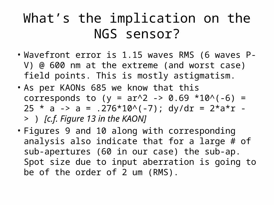
What’s the implication on the NGS sensor?
• Wavefront error is 1.15 waves RMS (6 waves P-V) @ 600 nm at the extreme (and worst case) field points. This is mostly astigmatism.
• As per KAONs 685 we know that this corresponds to (y = ar^2 -> 0.69 *10^(-6) = 25 * a -> a = .276*10^(-7); dy/dr = 2*a*r -> ) [c.f. Figure 13 in the KAON]
• Figures 9 and 10 along with corresponding analysis also indicate that for a large # of sub-apertures (60 in our case) the sub-ap. Spot size due to input aberration is going to be of the order of 2 um (RMS).

NGS wavefront sensor parameters• Based on the pupil geometry, we design the sensor to have 60
sub-apertures across the a circle that inscribes the Keck primary mirror. We also support another calibration mode with 5x5 pupil samples across the Keck primary mirror.
• The detector plate scale is 4” because the sensor needs to track extended objects that are 4” in diameter. One could also work out the spot size.

Modes of operation
• 60x60 mode of operation - since all the visible wavefront sensing detectors are identical (for spares and cost consideration in procurement and software development) in the NGAO we use 4 physical pixels per sub-ap. Which can be binned on chip and read as 2x2 pixels/sub-aperture with almost zero read noise penalty. This gives us the flexibility of 2 modes, one with high linearity and another with lower read noise.
• 5x5 mode of operation – to simply the size of moving parts while facilitating the two pupil sampling modes, we use the same collimator for both configurations. The table in the next page summaries all the design parameters.
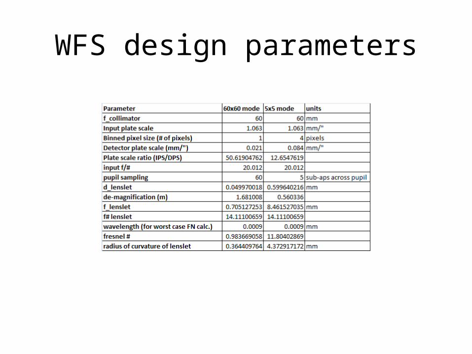
WFS design parameters
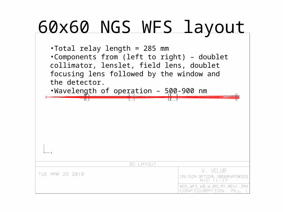
60x60 NGS WFS layout•Total relay length = 285 mm•Components from (left to right) – doublet collimator, lenslet, field lens, doublet focusing lens followed by the window and the detector.•Wavelength of operation – 500-900 nm

60x60 NGS WFS layout21 um pixel detector with 60 spots with 4x4 pixels/sub-aperture.

60x60 NGS WFS layout

60x60 NGS WFS post lenslet relay•Mag. = 1.681•Total relay length = 164 mm

Post lenslet relay – spots delivered by the relay
(Huygen’s) PSF Strehl = 99.2% at worst field point.

Post lenslet relay – grid distortion700 nm is the central wavelength, GD at 500 nm is 0.047% and GD at 900 nm is 0.013%

5x5 NGS (calibration) WFS layout•Total relay length = 265 mm•Components from (left to right) – doublet collimator, lenslet, field lens, doublet focusing lens followed a field flattener detector window and the focal plane array.•Wavelength of operation – 500-900 nm
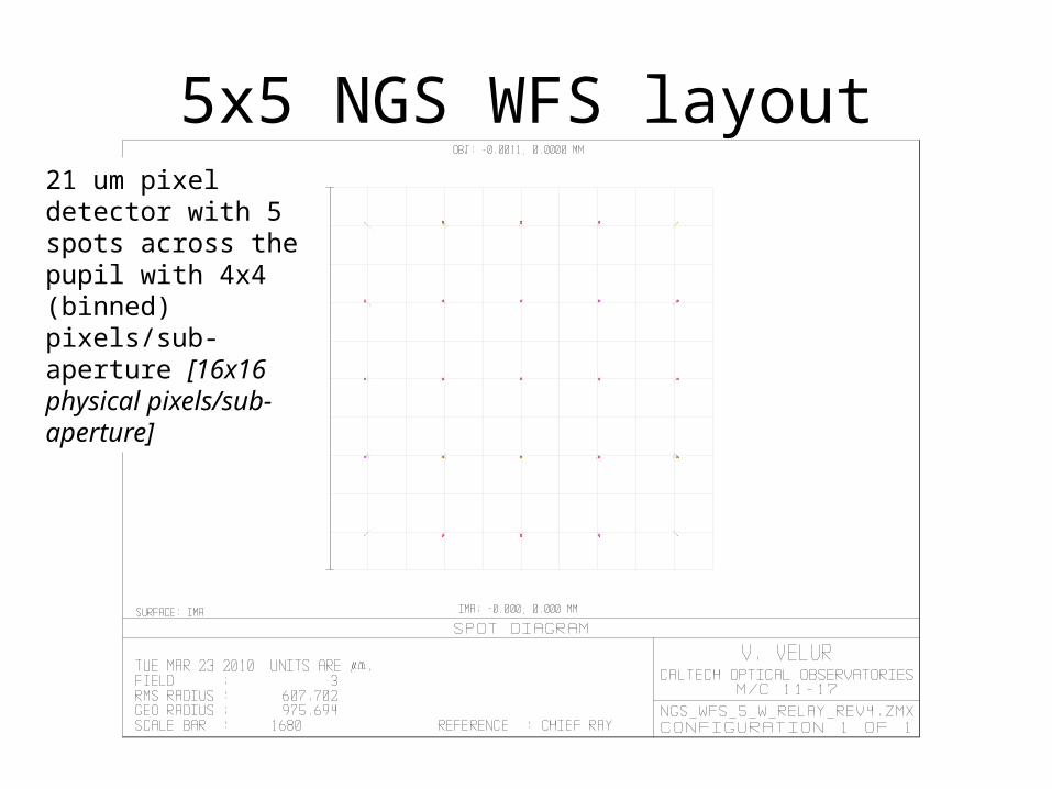
5x5 NGS WFS layout21 um pixel detector with 5 spots across the pupil with 4x4 (binned) pixels/sub-aperture [16x16 physical pixels/sub-aperture]

5x5 NGS WFS layout

5x5 NGS WFS post lenslet relay•Mag. = -0.560•Total relay length = 137 mm

Post lenslet relay – spots delivered by the relay
(Huygen’s) PSF Strehl = 95% at worst field point.
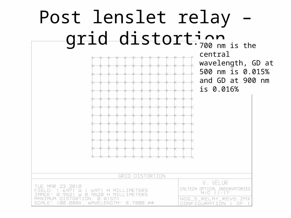
Post lenslet relay – grid distortion700 nm is the central wavelength, GD at 500 nm is 0.015% and GD at 900 nm is 0.016%