nfpa standards development site first draft report · metric units of measurement in this standard...
TRANSCRIPT
NFPA 302®, Fire Protection Standard for Pleasure and Commercial Motor Craft, 2010 Edition
NFPA STANDARDS DEVELOPMENT SITEFIRST DRAFT REPORTClosing Date: February 22, 2013 NOTE: All Public Comment must be received by 5:00 pm EST/EDST on the published Closing Date.
Quick Print
PIs [1]
PIs [1]
Chapter 1 Administration
1.1 Scope.
1.1.1
This standard shall establish minimum requirements for the prevention of fire and explosion, for mitigation of carbon monoxidehazards, and for life safety in case of fire, on boats specified in Section 1.3.
1.1.2
This standard shall establish minimum requirements for the following:
(1) Elimination of ignition sources
(2) Ventilation of accommodation spaces, fuel tank compartments (if separate from machinery spaces), and machinery spaces
(3) Use of combustible materials
(4) Fire-extinguishing equipment and fire exits
(5) Control of fire-extinguishing agents in machinery spaces
(6) Mitigation of carbon monoxide hazards from all sources
1.2 Purpose.
1.2.1
The purpose of this standard shall be to minimize the loss of life and property due to fires, explosions, and carbon monoxide aboardpleasure and commercial vessels.
1.2.2
The intent of this standard shall be to make motor craft as free from the hazards of fire and carbon monoxide as practicable.
1.2.3
The requirements of this standard shall be considered necessary to provide a reasonable level of protection from loss of life andproperty from fire, explosion, and carbon monoxide and reflect the conditions and the state of the art at the time the standard wasissued.
1.3 Application.
1.3.1
This standard shall apply to the following boats of less than 300 gross tons that are used for pleasure or commercial purposes:
(1) Boats that use engines for propulsion
(2) Boats that use engines for generating power
(3) Boats that use cooking, heating, or auxiliary appliances
(4) Boats that have permanently installed ignition source(s)
(5) Boats that have permanently installed electrical systems
1.3.2
This standard shall not apply to personal watercraft.
1.3.3
No requirement of this standard shall be construed as reducing applicable federal regulations.
1.4 Retroactivity.
It is not intended that the provisions of this standard be applied to boats constructed or equipment installed prior to the effectivedate of the standard.
1.5 Equivalency.
Nothing in this standard shall prevent the use of systems, methods, or devices of equivalent or superior quality, strength, fireresistance, effectiveness, durability, and safety in place of those required by the standard, provided that technical documentation issubmitted to the authority having jurisdiction to demonstrate equivalency.
1.6* Units.
http://submittals.nfpa.org/TerraViewWeb/ContentFetcher?contentId=302...
1 of 2 6/13/2014 2:15 PM

Metric units of measurement in this standard are in accordance with the modernized metric system known as the InternationalSystem of Units (SI). The liter unit, which falls outside of but is recognized by SI, is used commonly in international fire protection.These units are listed in Table 1.6 with their conversion factors.
Table 1.6 Unit Conversion Factors
Name of Unit Unit Symbol Conversion Factor
Millimeter mm 1 in. = 25.4 mm
Meter m 1 in. = 0.0254 m
Square centimeter cm2 1 in.2 = 6.452 cm2
Square meter m2 1 ft2 = 0.093 m2
Cubic centimeter cm3 1 in.3 = 16.39 cm3
Cubic meter m3 1 ft3 = 0.0283 m3
Gram g 1 oz = 28.35 g
Liter L 1 gal = 3.785 L
Kilopascal kPa gauge 1 psi = 6.89 kPa gauge
Bar bar 14.50 psi = 1 bar
Cubic meters per minute m3/min 1 cfm = 0.0283 m3/min
1.6.1
If a value for a required measurement in this standard is followed by an equivalent value in metric units, the first stated value shallbe regarded as the requirement, and the equivalent value that follows shall be approximate.
1.6.2
The metric unit value shall be the requirement for motor craft under the jurisdiction of Canadian authorities.
http://submittals.nfpa.org/TerraViewWeb/ContentFetcher?contentId=302...
2 of 2 6/13/2014 2:15 PM
NFPA 302®, Fire Protection Standard for Pleasure and Commercial Motor Craft, 2010 Edition
NFPA STANDARDS DEVELOPMENT SITEFIRST DRAFT REPORTClosing Date: February 22, 2013 NOTE: All Public Comment must be received by 5:00 pm EST/EDST on the published Closing Date.
Quick Print
FR-18 Hide Legislative
FR-4 Hide Legislative
FR-13 Hide Legislative
FR-14 Hide Legislative
Chapter 2 Referenced Publications
2.1 General.
The documents or portions thereof listed in this chapter are referenced within this standard and shall be considered part of therequirements of this document.
2.2 NFPA Publications.
National Fire Protection Association, 1 Batterymarch Park, Quincy, MA 02169-7471.
NFPA 10, Standard for Portable Fire Extinguishers, 2007 2010 edition.
NFPA 12, Standard on Carbon Dioxide Extinguishing Systems, 2008 2011 edition.
NFPA 12A, Standard on Halon 1301 Fire Extinguishing Systems, 2009 edition.
NFPA 52, Vehicular Gaseous Fuel Systems Code, 2010 edition.
NFPA 70®, National Electrical Code®, 2008 2011 edition.
NFPA 255, Standard Method of Test of Surface Burning Characteristics of Building Materials, 2006 edition.
NFPA 303, Fire Protection Standard for Marinas and Boatyards, 2006 2011 edition.
NFPA 701, Standard Methods of Fire Tests for Flame Propagation of Textiles and Films, 2004 2010 edition.
NFPA 2001, Standard on Clean Agent Fire Extinguishing Systems, 2008 2012 edition.
NFPA 2010, Standard for Fixed Aerosol Fire-Extinguishing Systems, 2006 2010 edition.
2.3 Other Publications.
2.3.1 ABYC Publications.
American Boat & Yacht Council, Inc., 613 Third Street, Suite 10, Annapolis, MD 21403.
ABYC A-24, Carbon Monoxide Detection Systems, 2007.
ABYC A-28, Galvanic Isolators, July 2004 2008 .
ABYC A-31, Battery Chargers and Inverters, 2007 2010 .
ABYC E-11, AC and DC Electrical Systems on Boats, 2008 2012 .
ABYC TE-4, Lighting Protection , 2006.
ABYC TH-23, Design, Construction, and Testing of Boats in Consideration of Carbon Monoxide, 2004 2012 .
2.3.2 AMCA Publication.
Air Movement and Control Association, 30 West University Drive, Arlington Heights, IL 60004-1893.
AMCA/ANSI 210, Laboratory Methods of Testing Fans for Certified Aerodynamic Performance Rating, 1999 2007 .
2.3.3 ANSI Publication.
American National Standards Institute, 25 West 43rd Street, 4th Floor, New York, NY 10036.
ANSI Z21.57, Recreational Vehicle Cooking Gas Appliances, 2001 2010 .
http://submittals.nfpa.org/TerraViewWeb/ContentFetcher?contentId=302...
1 of 3 6/13/2014 2:16 PM

PIs [1] FR-12 Hide Legislative
FR-15 Hide Legislative
FR-16 Hide Legislative
2.3.4 ASTM Publications.
ASTM International, 100 Barr Harbor Drive, P.O. Box C700, West Conshohocken, PA 19428-2959.
ASTM A463/A463M, Standard Specification for Steel Sheet, Aluminum-Coated, by the Hot-Dip Process, 2006 edition 2010 .
ASTM A653/A653M, Standard Specification for Steel Sheet, Zinc-Coated (Galvanized) or Zinc-Iron Alloy-Coated (Galvannealed) bythe Hot-Dip Process, 2007 2011 .
ASTM B 97 B96/B96M , Specification for Copper-Silicon Alloy Plate, Sheet, Strip, and Rolled Bar for General Purposes andPressure Vessels, 1981 edition 2011 .
ASTM B122/B122 M, Standard Specification for Copper-Nickel-Tin Alloy, Copper-Nickel-Zinc Alloy (Nickel Silver), and Copper-Nickel Alloy Plate, Sheet, Strip, and Rolled Bar, 2006 edition 2011 .
ASTM B127, Standard Specification for Nickel-Copper Alloy (UNS N05500) Plate, Sheet, and Strip, 2005 edition 2009 .
ASTM B152/B152 M, Standard Specification for Copper Sheet, Strip, Plate, and Rolled Bar, 2006 edition 2009 .
ASTM D471, Standard Test Method for Rubber Property-Effect of Liquids, 2006 edition 2012 .
ASTM E84, Standard Test Method for Surface Burning Characteristics of Building Materials , 2012.
2.3.5 NEMA Publication.
National Electrical Manufacturers Association, 1300 North 17th Street, Suite 1847, Rosslyn, VA 22209.
NEMA/ANSI WD-6, Wiring Devices — Dimensional Requirements, 2002 2008 .
NEMA/ANSI 250, Enclosures for Electrical Equipment (1000 Volts Maximum), 2003 2008 .
2.3.6 SAE Publications.
Society of Automotive Engineers, 400 Commonwealth Drive, Warrendale, PA 15096.
SAE J378, Recommended Practice for Marine Engine Propulsion System Wiring, 2004 2011 .
SAE J1127, Standard for Low Voltage Battery Cable, 2005 2010 .
SAE J1128, Standard for Low Tension Voltage Primary Cable, 2005 2010 .
SAE J1171, External Ignition Protection for of Marine Electrical Devices, 2004 2011 .
SAE J1928, Devices Providing Backfire Flame Control for Gasoline Engines in Marine Applications, 2005 2012 .
SAE J2006, Standard on Marine Exhaust Hose, 2003.
SAE J2031, Standard for High Tension Ignition Cable, 2001 2012 .
http://submittals.nfpa.org/TerraViewWeb/ContentFetcher?contentId=302...
2 of 3 6/13/2014 2:16 PM
PIs [1] FR-2 Hide Legislative
FR-17 Hide Legislative
2.3.7 UL Publications.
Underwriters Laboratories Inc., 333 Pfingsten Road, Northbrook, IL 60062-2096.
ANSI/ UL 21, Standard for Safety LP Gas-Hose, 1995 2007 , Revised October 2006 2010 .
ANSI/UL 94, Tests for Flammability of Plastic Materials for Parts in Devices and Appliances , 2006 2010, Revised 2012 .
ANSI/UL 103, Standard for Safety Factory-Built Chimneys for Residential Type and Building Heating Appliances, 2006 2010,Revised 2012 .
ANSI/UL 217, Standard for Safety for Single and Multiple Station Smoke Alarms, 2006, Revised May 2007 2012 .
ANSI/UL 248, Series of Low Voltage Fuses, 2005 2011 .
ANSI/UL 310, Standard for Safety for Electrical Quick-Connect Terminals, 2005 2009 .
ANSI/ UL 474 Standard for Safety for Dehumidifiers, 2007 2009, Revised 2012 .
ANSI/UL 489, Standard for Safety for Molded-Case Circuit Breakers Molded-Case Switchers, and Circuit-Breaker Enclosures,2006 2009, Revised 2011 .
ANSI/UL 498, Standard for Safety for Attachment Plugs and Receptacles, 2007 2010 .
ANSI/UL 512 , Standard for Safety Fuseholders , 1996 .
ANSI/UL 817, Standard for Safety Cord Sets and Power-Supply Cords, 2007 2001, Revised 2011 .
ANSI/UL 858, Standard for Safety for Household Electric Ranges, 2005, Revised April 2006. 2012.
ANSI/UL 943, Standard for Safety for Ground-Fault Circuit-Interrupters, 2005 2006, Revised 2012 .
ANSI/UL 1059, Standard for Safety for Terminal Blocks, 2006 2001, Revised 2011 .
ANSI/UL 1077, Standard for Safety for Supplementary Protectors for Use in Electrical Equipment, 2006 2005, Revised 2010 .
UL 1128, Standard for Safety for Marine Blowers, 1997.
UL 1129, Standard for Safety for Wet Exhaust Component for Marine Engines, 1988 1999 .
UL 1133, Standard for Safety Boat Circuit Breakers , 1999.
UL 1426, Standard for Safety for Electrical Cables for Boats, 2001 2010 .
UL 1500, Standard for Safety for Ignition-Protection Test for Marine Products, 1997, Revised March 2007.
ANSI/UL 4248, Series of Standards for Safety for Fuseholders , 2011.
2.3.8 U.S. Government Publication.
U.S. Government Printing Office, Washington, DC 20402.
Title 33, Code of Federal Regulations, Part 183, “Boats and Associated Equipment.”
2.3.9 Other Publications.
Merriam-Webster’s Collegiate Dictionary, 11th edition, Merriam-Webster, Inc., Springfield, MA, 2003.
2.4 References for Extracts in Mandatory Sections.
NFPA 70®, National Electrical Code®, 2008 2011 edition.
NFPA 2001, Standard on Clean Agent Fire Extinguishing Systems, 2008 2012 edition.
http://submittals.nfpa.org/TerraViewWeb/ContentFetcher?contentId=302...
3 of 3 6/13/2014 2:16 PM

NFPA 302®, Fire Protection Standard for Pleasure and Commercial Motor Craft, 2010 Edition
NFPA STANDARDS DEVELOPMENT SITEFIRST DRAFT REPORTClosing Date: February 22, 2013 NOTE: All Public Comment must be received by 5:00 pm EST/EDST on the published Closing Date.
Quick PrintChapter 3 Definitions
3.1 General.
The definitions contained in this chapter shall apply to the terms used in this standard. Where terms are not defined in this chapteror within another chapter, they shall be defined using their ordinarily accepted meanings within the context in which they are used.Merriam-Webster’s Collegiate Dictionary, 11th edition, shall be the source for the ordinarily accepted meaning.
3.2 NFPA Official Definitions.
3.2.1* Approved.
Acceptable to the authority having jurisdiction.
3.2.2* Authority Having Jurisdiction (AHJ).
An organization, office, or individual responsible for enforcing the requirements of a code or standard, or for approving equipment,materials, an installation, or a procedure.
3.2.3 Labeled.
Equipment or materials to which has been attached a label, symbol, or other identifying mark of an organization that is acceptableto the authority having jurisdiction and concerned with product evaluation, that maintains periodic inspection of production of labeledequipment or materials, and by whose labeling the manufacturer indicates compliance with appropriate standards or performance ina specified manner.
3.2.4* Listed.
Equipment, materials, or services included in a list published by an organization that is acceptable to the authority havingjurisdiction and concerned with evaluation of products or services, that maintains periodic inspection of production of listedequipment or materials or periodic evaluation of services, and whose listing states that either the equipment, material, or servicemeets appropriate designated standards or has been tested and found suitable for a specified purpose.
3.2.5 Shall.
Indicates a mandatory requirement.
3.2.6 Should.
Indicates a recommendation or that which is advised but not required.
3.2.7 Standard.
A document, the main text of which contains only mandatory provisions using the word “shall” to indicate requirements and which isin a form generally suitable for mandatory reference by another standard or code or for adoption into law. Nonmandatory provisionsshall be located in an appendix or annex, footnote, or fine-print note and are not to be considered a part of the requirements of astandard.
3.3 General Definitions.
3.3.1 Accessible.
Capable of being reached for inspection, maintenance, or removal without disturbing the permanent boat structure.
3.3.2 Accommodation Space.
Space designed for living purposes.
3.3.3 Battery Cold Cranking Rating.
The discharge load in amperes that a battery at 0°F (-17.8°C) can deliver for 30 seconds while maintaining a voltage of 1.2 volts percell or higher.
3.3.4 Battery Reserve Capacity.
The number of minutes for which a new, fully charged battery at 80°F (26.7°C) can be continuously discharged at 25 amperes whilemaintaining a voltage of 1.75 volts per cell or higher (10.5 volts for a 12-volt battery or 5.25 volts for a 6-volt battery).
3.3.5 Bonding Conductor.
A normally non-current-carrying conductor that is intended to carry leakage current from either the ac or the dc system. Bondingconductors connect underwater metallic objects as part of any cathodic protection system and, if sized in accordance with ABYCTE-4, shall be permitted to serve as lightning grounding conductors. If used, they shall be colored green or green with yellow stripe,or shall be of bare copper.
3.3.6 Butane.
See 3.3.27, Liquefied Petroleum Gas (LPG).
3.3.7 Candela (cd).
A unit of measure used in measuring the effective intensity of a flashing light.
Global FR-46 Hide Deleted
http://submittals.nfpa.org/TerraViewWeb/ContentFetcher?contentId=302...
1 of 4 6/13/2014 2:17 PM

FR-46 Hide Legislative
PIs [1]
3.3.8* Clean Agent.
Electrically nonconducting, volatile, or gaseous fire extinguishant that does not leave a residue upon evaporation. The word “agent”as used in this document means “clean agent” unless otherwise indicated. [ 2001, 2008 2012 ]
3.3.9* Compressed Natural Gas (CNG).
A natural lighter-than-air gas compressed for use as a fuel that consists principally of methane in gaseous form plus naturallyoccurring mixtures of hydrocarbon gases.
3.3.10 Double Insulation System.
An insulation system comprised of basic insulation and supplementary insulation, with the two insulations physically separated andso arranged that they are not simultaneously subjected to the same deteriorating influences (temperature, contaminants, and thelike).
3.3.11* Engine Exhaust System.
The means by which products of combustion are conducted from the engine exhaust manifold to an outboard terminus.
3.3.12 Engine Negative Terminal.
The point on the engine at which the negative battery cable is connected.
3.3.13 Flammable Hydrocarbon Mixture.
A mixture of gasoline vapor and air, or propane plus air, between the lower explosive limit (LEL) and upper explosive limit (UEL).
3.3.14 Galvanic Isolator.
A device installed in series with the ac grounding (green, or green with yellow stripe) conductor of the shore power cable to block, ineffect, the low-voltage dc galvanic current flow, yet permit the passage of ac current normally associated with the ac grounding(green, or green with yellow stripe) conductor.
3.3.15* Galvanically Compatible Metals.
Metals that are related closely to each other in the galvanic series.
3.3.16 Gross Ton.
A measure of internal volume equal to 100 ft3.
3.3.17 Ground.
The electrical potential of the earth's surface. The boat's ground is established by a conducting connection (intentional oraccidental) with the earth, including any conductive part of the wetted surface of a hull.
3.3.18 Grounded Conductor.
3.3.18.1 Alternating Current (ac) Grounded Conductor.
A current-carrying conductor that is intentionally maintained at ground potential.
3.3.18.2 Direct Current (dc) Grounded Conductor.
A current-carrying conductor connected to the side of the power source that is intentionally maintained at boat ground potential.
3.3.19 Ground-Fault Circuit-Interrupter (GFCI).
A device intended for the protection of personnel that functions to de-energize a circuit or portion thereof within an establishedperiod of time when a current to ground exceeds the values established for a Class A device.
FPN: Class A ground-fault circuit interrupters trip when the current to ground is 6 mA or higher and do not trip when the current toground is less than 4 mA. For further information, see UL 943, Standard for Ground-Fault Circuit Interrupters. [70: 100.1]
3.3.20 Ground-Fault Protector (GFP).
A device intended to protect equipment by interrupting the electric current to the load when a fault current to ground exceeds apredetermined value that is less than that required to operate the overcurrent protection device of that supply circuit.
3.3.21 Grounding Conductor.
3.3.21.1 Alternating Current (ac) Grounding Conductor (green or green with yellow stripe).
A conductor, not normally carrying current, used to connect the metallic non-current carrying parts of electrical equipment to the acsystem and engine negative terminal, or its bus, and to the shore ac grounding conductor through the shore power cable.
3.3.21.2 Direct Current (dc) Grounding Conductor.
A normally non-current-carrying conductor used to connect metallic non-current-carrying parts of a direct current device to theengine negative terminal or its bus for the purpose of minimizing stray current corrosion.
3.3.22* Halocarbon Agent.
An agent that contains as primary components one or more organic compounds containing one or more of the elements fluorine,chlorine, bromine, or iodine.
3.3.23* Halogenated Agent.
Bromochlorodifluoromethane (Halon 1211), bromotrifluoromethane (Halon 1301), and mixtures of Halon 1211 and Halon 1301.
3.3.24* Ignition Protection.
The design and construction of a device such that, under the designed operating conditions, the device does not initiate ignitionwhen surrounded by a flammable hydrocarbon mixture if an ignition source causes an internal explosion, the device is incapable ofreleasing sufficient electrical or thermal energy to ignite a hydrocarbon mixture, and the source of ignition is hermetically sealed.
http://submittals.nfpa.org/TerraViewWeb/ContentFetcher?contentId=302...
2 of 4 6/13/2014 2:17 PM
3.3.25 Ignition Source.
Any item or substance capable of an energy release of a type and magnitude sufficient to ignite any flammable mixture of gases orvapors that could occur onboard the vessel.
3.3.26 Inboard Engine.
Any internal combustion engine other than an outboard engine permanently mounted within the hull.
3.3.27* Liquefied Petroleum Gas (LPG).
Terms “liquefied petroleum gas,” “LP-Gas,” and “LPG” that are synonymous and include any product composed predominantly ofany of the following gaseous hydrocarbons: propane, propylene, butane, isobutane, butylenes, or a mixture thereof.
3.3.28 Machinery Space.
Spaces that contain permanently installed engines for mechanical or electrical power or propulsion.
3.3.29 Motor Craft.
Any boat that is propelled by other than wind or human power.
3.3.30 Open to the Atmosphere.
A space or compartment that has at least 15 in.2 of net open area directly exposed to the atmosphere for each cubic foot of net
compartment volume (0.34 m2/m3).
3.3.31 Overcurrent Protection Device.
A device, such as a fuse or circuit breaker, designed to interrupt the circuit when the current flow exceeds a predetermined value.
3.3.32* Panelboard.
An assembly of devices for the purpose of controlling or distributing, or both, electrical power on a boat.
3.3.33* Permanently Installed.
Securely fastened so that tools must be used for removal.
3.3.34 Personal Watercraft.
A vessel less than 13 ft (4 m) in length that uses an internal combustion engine powering a water jet pump as its primary source ofpropulsion and is designed to be operated by a person or persons sitting, standing, or kneeling on rather than within the confines ofthe hull.
3.3.35 Pigtail.
An external conductor that originates within an electrical component or appliance installed by the manufacturer.
3.3.36* Polarized System (ac).
A system in which the grounded (white) and ungrounded conductors are connected identically in relation to all terminals or fixtureleads on all devices in the circuit, including the shore power connections.
3.3.37 Polarized System (dc).
A system in which the grounded (negative) and ungrounded (positive) conductors are connected identically in relation to allterminals or leads on all devices in the circuit.
3.3.38 Propane.
See 3.3.27, Liquefied Petroleum Gas (LPG).
3.3.39 Readily Accessible.
Capable of being reached quickly and safely for effective use under emergency conditions without the aid of tools.
3.3.40 Self-Limiting.
A device with a maximum output restricted to a specified value by its magnetic and electrical characteristics.
3.3.41* Sheath.
A material used as a continuous protective covering around one or more insulated conductors.
3.3.42 Shore Power Inlet.
A reverse service-type fitting designed for mounting on a boat that requires a female connector on the shore power cable in order tomake the electrical connection.
3.3.43 Transformer.
3.3.43.1 Isolation Transformer.
A transformer installed in the shore power supply circuit of a boat to isolate electrically all ac system conductors, including the acgrounding conductor (green, or green with yellow stripe) on the boat, from the ac system conductors of the shore power supply.
3.3.43.2 Polarization Transformer.
An isolated winding transformer (“dry-type” encapsulated lighting transformer) installed in the shore power supply circuit of a boat toisolate electrically the normally current-carrying ac system conductors, but not the ac grounding conductor (green, or green withyellow stripe), from the normally current-carrying conductors of the shore power supply.
3.3.44 Trip-Free Circuit Breaker.
A resettable overcurrent protection device designed so that the means of resetting cannot override the current interruptingmechanism.
Global FR-3 Hide Deleted
http://submittals.nfpa.org/TerraViewWeb/ContentFetcher?contentId=302...
3 of 4 6/13/2014 2:17 PM

PIs [1] FR-3 Hide Legislative
3.3.45* Ventilation.
The changing of air within a compartment by natural or mechanical powered means.
3.3.46 Watertight.
So constructed that water does not enter the enclosure under test conditions specified in NEMA/ANSI 250-6, Enclosures forElectrical Equipment (1000 Volts Maximum).
3.3.47* Weatherproof.
Constructed or protected so that exposure to the weather does not interfere with successful operation.
http://submittals.nfpa.org/TerraViewWeb/ContentFetcher?contentId=302...
4 of 4 6/13/2014 2:17 PM
NFPA 302®, Fire Protection Standard for Pleasure and Commercial Motor Craft, 2010 Edition
NFPA STANDARDS DEVELOPMENT SITEFIRST DRAFT REPORTClosing Date: February 22, 2013 NOTE: All Public Comment must be received by 5:00 pm EST/EDST on the published Closing Date.
Quick Print
PIs [1] FR-5 Hide Legislative
FR-6 Hide Legislative
Chapter 4 Hull
4.1 General Arrangement.
4.1.1
The hull shall be arranged so that all compartments are accessible and all escape hatches are unobstructed and readily accessible.
4.1.1.1
Every boat having enclosed accommodation spaces shall have a readily accessible and unobstructed means of egress.
4.1.1.2
Every boat having enclosed accommodation spaces shall have a second accessible means of egress if it is possible for one exit tobe blocked by a fire in a galley or machinery area.
4.1.1.3
The means of egress in 4.1.1.1 and 4.1.1.2 shall provide for minimum clear opening dimensions of 14 in. × 18 in. (36.8 cm × 47
cm) (rectangular); or 18 in. (45.7 cm) diameter (circular); or 270 in.2 (1741 cm2) with a minimum dimension of 141⁄2 in. (36.8 cm)(oval).
4.1.1.4
Any hatch that is required for egress shall have a means of being operated from the inside and a means of being operated from theoutside when not secured from the inside.
4.1.1.5
All hinged hatches shall have a means or method to support the hatch in an open position.
4.1.2*
Bulkheads or enclosures shall be installed between machinery spaces and accommodation spaces.
4.1.2.1
Openings such as crevices, holes, joints, and penetrations for wiring, cable, and hose, etc., in bulkheads or decks betweenaccommodation compartment(s) that are adjacent to or above a compartment(s) that contains a gasoline engine shall beconstructed to minimize the flow of gas or vapors from the machinery space by means such as, but not limited to, flexiblecompounds.
4.1.3
Bulkheads or enclosures required in 4.1.2 shall be continuous, except for necessary penetrations, to minimize the escape offire-extinguishing agents discharged into the machinery space.
4.1.4
The requirements of 4.1.4 shall apply to boats other than boats using diesel fuel only.
4.1.4.1
Bilges of spaces containing fuel lines and fuel line fittings shall be separated from bilges of accommodation spaces and otherenclosed spaces containing sources of ignition by bulkheads that shall not permit more than 0.25 fl oz (7.4 ml) of leakage per hourwhen the liquid in the bilge is at a height of 12 in. (30 cm) or one-third the maximum height of the bulkhead, whichever is less.
4.1.4.2
Above heights of 12 in. (30 cm) or one-third the maximum height, the bulkhead shall be permitted to have openings for the passageof conductors, piping, ventilation ducts, mechanical equipment, doors, hatches, and access panels, provided that the maximumannular space around each item is not greater than 1⁄4 in. (6.4 mm).
4.1.5
Machinery spaces shall be readily accessible.
4.1.6 Thermal and Acoustical Insulation.
4.1.6.1
Materials used for thermal and acoustical insulation in any compartment or enclosure containing an internal combustion engine orheater shall have a flame spread index of 75 or less, when tested in accordance with ASTM E 84, Standard Test Method forSurface Burning Characteristics of Building Materials .
4.1.6.2
Material shall be labeled or listed as having been tested to meet the requirements of NFPA 255 , Standard Method of Test ofSurface Burning Characteristics of Building Materials ASTM E 84, Standard Test Method for Surface Burning Characteristics ofBuilding Materials .
http://submittals.nfpa.org/TerraViewWeb/ContentFetcher?contentId=302...
1 of 5 6/13/2014 2:17 PM
4.1.6.3
Materials used for thermal and acoustical insulation shall not disintegrate in the presence of hydrocarbon vapor.
4.1.6.4
Materials used for thermal and acoustical insulation shall be designed and installed such that hydrocarbon vapors cannotaccumulate within the material and thereby reduce its flame spread rate.
4.2 Spaces Open to the Atmosphere.
4.2.1 Spaces Connected to Spaces Open to the Atmosphere.
4.2.1.1
Compartments or spaces connecting with engine or portable fuel tank spaces that are open to the atmosphere shall require
ventilation if the connecting space has an open area of less than 15 in.2/ft3 (0.34 m2/m3) of its net volume.
4.2.1.2
The open area in 4.2.1.1 shall be open either to the atmosphere or to another open space, provided that, for the combined net
volumes of the connecting spaces, there is a total area open to the atmosphere of at least 15 in.2/ft3 (0.34 m2/m3).
4.2.2
Long, narrow spaces formed by side panels or accommodation floors shall have openings at both ends or along the sides if they areto be considered open to the atmosphere.
4.3* Natural Ventilation.
4.3.1
Each compartment not open to the atmosphere shall be provided with a natural ventilation system where such a compartmentcontains any of the following:
(1) Permanently installed gasoline engine
(2) Portable fuel tank that vents into the compartment
(3) Gasoline tank and an electrical component without ignition protection
4.3.2*
Space under a motor well in outboard boats not open to the atmosphere, that is large enough to accommodate a 6 gal (23 L)portable fuel tank but is not intended for such usage, shall be labeled to prohibit its use for fuel storage.
4.3.3
Each natural ventilation system shall be constructed with at least one intake and one exhaust opening that shall be located on theboat's exterior surface.
4.3.4*
Each compartment requiring natural ventilation shall be equipped with an exhaust duct(s) originating in the lower third of thecompartment, with the duct opening permanently fixed above the normal accumulation of bilge water.
4.3.5
If the compartment requiring natural ventilation is an engine compartment, the exhaust duct(s) shall be located as near below theengine(s) as practicable.
4.3.6
An exhaust duct fitted with a cowl or its equivalent shall face aft.
4.3.7
Air intake openings inside a compartment shall be separated from exhaust duct openings inside the compartment by at least 24 in.(610 cm), compartment dimensions permitting.
http://submittals.nfpa.org/TerraViewWeb/ContentFetcher?contentId=302...
2 of 5 6/13/2014 2:17 PM
PIs [1] FR-33 Hide Legislative
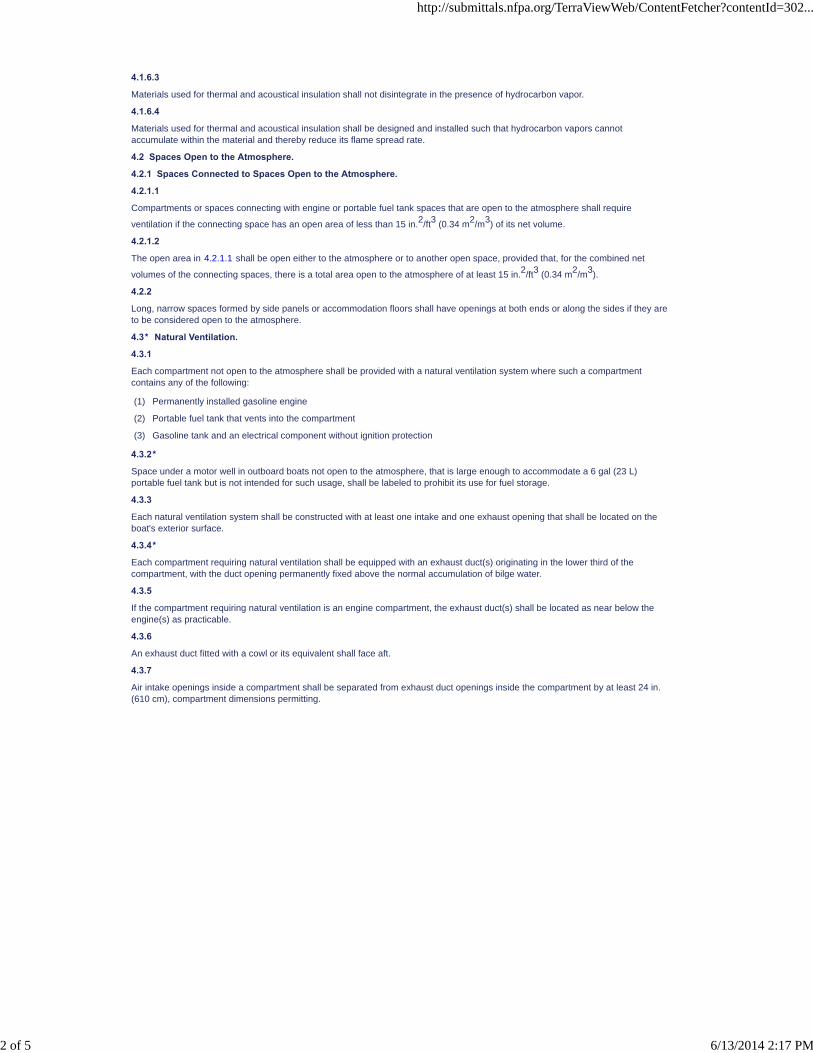
4.3.8
The minimum aggregate internal cross-sectional area of intake ducts or openings shall be as shown in Figure 4.3.8.
Figure 4.3.8 Area of Openings.
4.3.9
The minimum aggregate internal cross-sectional area of exhaust ducts or openings shall be calculated in the same manner as forintakes. (See 4.3.8.)
4.3.10*
Duct size shall be based on nominal diameters and shall be at least 21⁄2 in. (64 mm) in diameter.
4.3.11*
Duct openings shall be of at least equivalent cross-sectional area of the duct.
4.3.12
The minimum cross-sectional area of terminal fittings for flexible ventilation ducts shall be not less than 80 percent of the requiredinternal cross-sectional area of the flexible ventilation duct.
4.4 Connecting Compartments or Spaces by a Natural Ventilation System.
4.4.1
A natural ventilation system shall be provided for each compartment in a boat, except those open to the atmosphere, that containsany of the following:
(1) Permanently installed gasoline engine
(2) Permanently installed fuel tank and an electrical component without ignition protection
(3) Portable fuel tank
(4) Nonmetallic fuel tank that has an aggregate permeability rate exceeding 0.04 oz (1.2 g) of fuel loss in 24 hours per cubic footof net compartment volume using reference fuel “C” at 104°F ± 36°F (40°C ± 2°C) from ASTM D 471, Standard Test Methodfor Rubber Property-Effect of Liquids
(5) If no tank described in 4.4.1(4) is present, openings between the compartment and a compartment that requires ventilationwhere the aggregate area of such openings exceeds 2 percent of the area between the compartments
4.4.2
Each required supply opening shall be located on the exterior surface of the boat.
4.4.3
An accommodation compartment located above a compartment requiring ventilation that is separated from the compartmentrequiring ventilation by a deck or other enclosure shall not be considered a connecting compartment.
4.5 Powered Ventilation System.
http://submittals.nfpa.org/TerraViewWeb/ContentFetcher?contentId=302...
3 of 5 6/13/2014 2:17 PM
PIs [1] FR-7 Hide Legislative
FR-48 Hide Legislative
FR-8 Hide Legislative
4.5.1
Each compartment not open to the atmosphere that has a permanently installed gasoline engine with a cranking motor shall beventilated by an exhaust blower.
Global FR-7 Hide Deleted
4.5.1.1
Each compartment not open to the atmosphere that has a permanently installed internal combustion engine with a cranking motorand a fixed fire extinguishing system shall be ventilated by an exhaust blower to remove any by-products of combustion orremaining extinguishing agent after the discharge of a fixed fire extinguishing system..
4.5.2 Blowers.
4.5.2.1
Blowers shall be designed for continuous operation at 120 percent of nominal voltage.
4.5.2.2*
Blowers shall meet the external ignition protection requirements of UL 1128, Standard for Safety for Marine Blowers, or UL 1500,Standard for Safety for Ignition-Protection Test for Marine Products.
4.5.2.3
Blowers shall be rated for airflow in cubic feet per minute, at nominal voltage, in accordance with Figure 12 of AMCA/ANSI 210,Laboratory Methods of Testing Fans for Aerodynamic Performance Rating, or UL 1128, Standard for Safety Marine Blowers. (SeeFigure 4.5.3.1.)
4.5.3 Installation of Powered Ventilation.
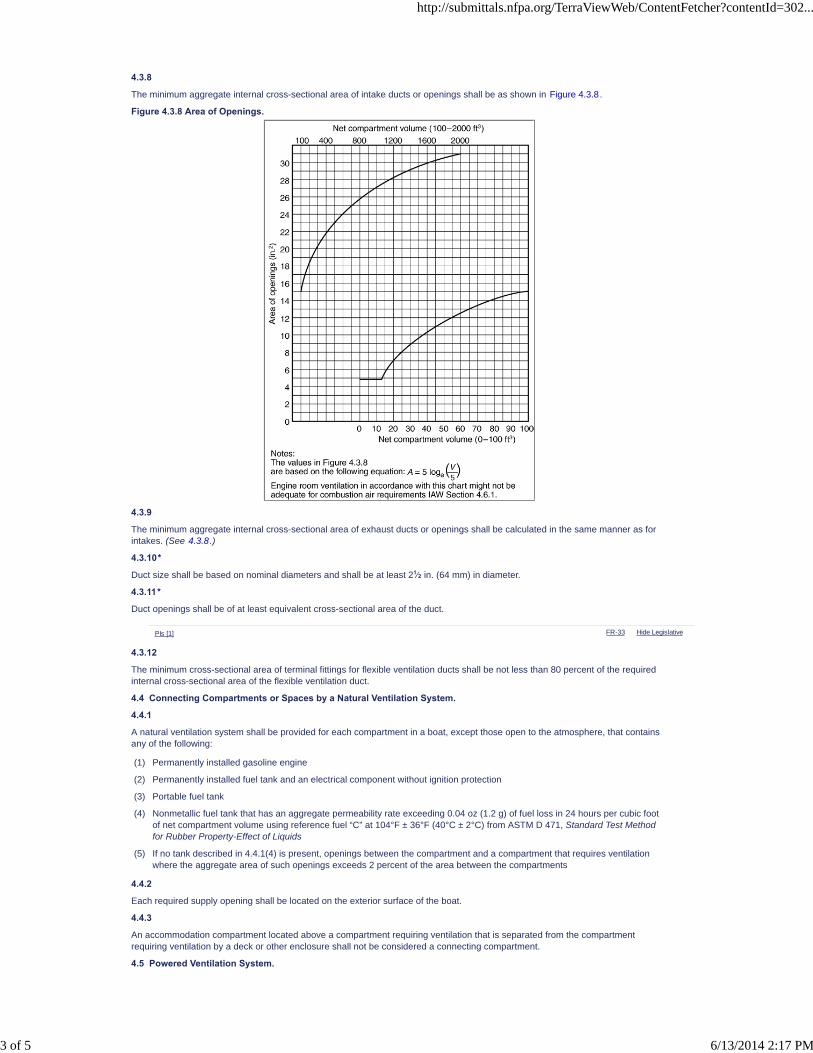
4.5.3.1
Blower(s) capacity shall be selected in accordance with the blower capacity curve in Figure 4.5.3.1.
Figure 4.5.3.1 Minimum Blower Capacity and System Performance.
4.5.3.2
More than one blower shall be permitted to be installed to meet the requirements of 4.5.3.1.
Global FR-8 Hide Deleted
4.5.3.2.1
Each blower shall be separately circuited and protected internally at the equipment or by branch-circuit overcurrent devicessuitable for motor current.
http://submittals.nfpa.org/TerraViewWeb/ContentFetcher?contentId=302...
4 of 5 6/13/2014 2:17 PM

4.5.3.3
As installed, the blower system(s) shall exhaust air from the boat at a rate in accordance with the system performance curve(blower system output) in Figure 4.5.3.1 when the engine is not operating and the blower is operating at the electrical system'snominal voltage.
4.5.3.4
Blowers that are not submersible blower motors shall be mounted above the normal level of accumulated bilge water.
4.5.3.5
Blowers shall be installed with ducts having intake openings that meet the following criteria:
(1) They shall be permanently secured.
(2) They shall be located in the lower third of the compartment.
(3) They shall be located above the normal level of accumulated bilge water with the boat at rest.
(4) They shall be located as near below the engine(s) that they serve as practicable.
4.5.3.6
Electrical wiring shall be installed in accordance with Chapter 9 or Chapter 10.
4.5.3.7 Warning Label.
4.5.3.7.1
Each boat that requires a powered ventilation system shall display a warning label located in plain view of the operator and locatedas close as practicable to each ignition switch (including auxiliary equipment).
4.5.3.7.2
The warning label required by 4.5.3.7.1 shall contain at a minimum the following informational elements:
WARNING:Gasoline vapors can explode, resulting in injury or death.Before starting engine:(1) Check engine compartment bilge for gasoline or vapors.(2) Operate blower for 4 minutes. (3) Verify blower operation.
4.6 Arrangements of Openings.
4.6.1
Ventilation openings shall be located to prevent the entrance of water in amounts that could impair the stability or handling of thevessel or that could cause machinery malfunction under normal operating conditions.
4.6.2
External openings of intakes and exhausts shall be located to minimize the re-entry of exhausted fumes.
4.6.2.1
On boats with accommodation compartments there shall be no engine ventilation system openings in aft-facing surfaces at thestern.
Exception: Where testing in accordance with ABYC TH-23, Design, Construction, and Testing of Boats in Consideration of CarbonMonoxide, indicates that machinery or tank compartments connected to these openings do not have sustained accumulated levelsof carbon monoxide (CO) in excess of 125 ppm.
4.6.3* Fuel Vapors.
4.6.3.1
External openings of intakes and exhausts shall be located and oriented to prevent entry of fuel vapors.
4.6.3.2
The location of intake and exhaust ventilation openings shall be no less than 15 in. (38 cm) from the fuel fill and fuel vent fittings, asmeasured in a straight line or across any intervening surface(s).
4.6.4
Ventilation openings shall be unobstructed by side curtains, cockpit enclosures, dodgers, and other weather enclosures.
4.7* Combustion Air.
Ventilating provisions and openings to the machinery space provided for supplying combustion air shall accommodate at least thesum of the maximum air requirements specified by the engine manufacturer(s) for each propulsion and auxiliary engine(s) in thatspace.
http://submittals.nfpa.org/TerraViewWeb/ContentFetcher?contentId=302...
5 of 5 6/13/2014 2:17 PM

NFPA 302®, Fire Protection Standard for Pleasure and Commercial Motor Craft, 2010 Edition
NFPA STANDARDS DEVELOPMENT SITEFIRST DRAFT REPORTClosing Date: February 22, 2013 NOTE: All Public Comment must be received by 5:00 pm EST/EDST on the published Closing Date.
Quick Print
PIs [1] FR-10 Hide Legislative
Chapter 5 Engines
5.1 Exposed Engine Surface Temperatures.
5.1.1
Exposed engine surfaces, except the surfaces addressed in 5.1.2, shall not exceed 200°F (94°C) under normal operatingconditions.
5.1.2
The requirements of 5.1.1 shall not apply to short branch connections between liquid-cooled exhaust manifolds and cylinder headexhaust ports or to hot spots on intake manifolds.
5.1.3
An audible or visual device shall be installed to warn of engine temperatures that exceed 200°F (94°C).
5.2 Diaphragm-Type Gasoline Pumps.
5.2.1
Gasoline engine fuel pumps of the diaphragm type shall be designed so that fuel shall not be released to the engine space if aprimary diaphragm failure occurs.
5.2.2
Gasoline engine fuel pumps of the diaphragm type shall be provided with a means to determine that a diaphragm failure hasoccurred without dismantling the fuel pump.
5.3* Marine Carburetors.
5.3.1
Marine carburetors shall not leak more than 0.17 fl oz (5 ml) of fuel in 30 seconds under either of the following conditions:
(1) When the float valve is open, the carburetor is at half throttle, and the engine is cranked without having been started
(2) When the fuel pump is delivering the maximum pressure specified by its manufacturer
5.3.2
Each updraft and horizontal draft carburetor shall have a device that performs the following functions:
(1) Collects and holds fuel that flows out of the carburetor venturi section toward the air intake
(2) Prevents collected fuel from being carried out of the carburetor assembly by the shock wave of a backfire or by reverse airflow
(3) Returns collected fuel to the engine induction system after the engine starts
5.3.3*
Spark ignition engine air intakes shall be fitted with one of the following means of backfire flame control:
(1) Backfire flame control approved by the U.S. Coast Guard and bearing a U.S. Coast Guard approval number
(2) Backfire flame control meeting the requirements of SAE J1928, Devices Providing Backfire Flame Control for GasolineEngines in Marine Applications
(3) An engine-air and fuel induction system that provides adequate protection from propagation of backfire flame to theatmosphere equivalent to that provided by an acceptable backfire flame arrester and includes a reed valve assembly
5.4 Electrical Components.
Electrical components for engines shall comply with the applicable provisions of Chapter 9 and Chapter 10.
5.5 Air-Cooled Engines.
5.5.1
Permanently installed air-cooled engines with self-contained fuel systems shall be located only on open decks or on cabin tops.
5.5.2
Any housing over engines addressed in 5.5.1 shall be open whenever the engine is operating.
5.5.3 Enclosed Air-Cooled Engines.
5.5.3.1
Factory-installed engine air-cooling shrouding shall be constructed and mounted for enclosed air-cooled engines to trap all engine-cooling air and lead it to a point from which it can be discharged outside the hull or engine box by means of ducting.
5.5.3.2 Duct Material.
5.5.3.2.1
Ducts for engine-cooling air shall have a flame spread index of 75 or less, when tested in accordance with ASTM E 84, StandardTest Method for Surface Burning Characteristics of Building Materials .
http://submittals.nfpa.org/TerraViewWeb/ContentFetcher?contentId=302...
1 of 2 6/13/2014 2:17 PM
FR-11 Hide Legislative
5.5.3.2.2
Material used for ducts for engine-cooling air shall be labeled or listed as having been tested to meet the requirements of NFPA255 , Standard Method of Test of Surface Burning Characteristics of Building Materials ASTM E 84, Standard Test Method of Testof for Surface Burning Characteristics of Building Materials . .
5.5.3.3
Engine-cooling air shall not be used as a direct source for heating accommodation spaces.
5.6 Portable Gasoline Tanks.
Portable gasoline engines with integral fuel tanks or portable gasoline fuel tanks shall be stowed securely in an open or ventilatedspace in accordance with Sections 4.2 and 9.8 so that fuel or vapors cannot reach interior spaces.
5.7 Automatic Shutdown.
Nonpropulsion engines intended for automatic operation shall be equipped with an automatic shutdown device actuated by low oilpressure, excessive engine overheat, and excess heat from exhaust pipe or exhaust gas ducting.
5.8* High-Tension Cable.
High-tension cable assemblies shall conform to SAE J2031, Standard for High Tension Ignition Cable.
5.9* Distributors.
Ignition distributors shall conform to UL 1500, Standard for Safety Ignition-Protection Test for Marine Products.
http://submittals.nfpa.org/TerraViewWeb/ContentFetcher?contentId=302...
2 of 2 6/13/2014 2:17 PM

NFPA 302®, Fire Protection Standard for Pleasure and Commercial Motor Craft, 2010 Edition
NFPA STANDARDS DEVELOPMENT SITEFIRST DRAFT REPORTClosing Date: February 22, 2013 NOTE: All Public Comment must be received by 5:00 pm EST/EDST on the published Closing Date.
Quick Print
PIs [1]
PIs [1] FR-19 Hide Legislative
PIs [1]
Chapter 6 Engine Exhaust Systems
6.1 General Requirements.
6.1.1
Exhaust systems shall comply with the following:
(1) They shall be gastight to hull interiors.
(2) All connections shall be accessible.
(3) They shall be supported to minimize failure from vibration, shock, expansion, and contraction.
(4) They shall have no threaded fittings into nonmetallic exhaust system components.
(5) They shall have no discharge from other devices into the exhaust other than from engine-cooling water.
Global FR-19 Hide Deleted
6.1.1.1
In addition to the requirements of 6.1.1 , exhaust systems on gasoline engines shall be designed and installed to reduce theproduction of carbon monoxide by providing the minimum restrictions to exhaust gas flow practicable.
6.1.2
Wherever personnel or combustibles can come in contact with hot surfaces, effective protection shall be provided by water-jacketing, lagging, or shielding, or by guards or engine enclosures.
6.1.3 Exhaust Supports.
6.1.3.1
For wet exhaust systems, hangers, brackets, or other means used to support metallic exhaust systems shall be noncombustiblewithin 6 ft (1.8 m) of the engine connection(s).
6.1.3.2
For dry exhaust systems, hangers, brackets, or other means used to support metallic exhaust systems shall be noncombustible.
6.1.4
Except for outboard engines, a means to indicate loss of exhaust-cooling water shall be provided so that it is effective at all helmpositions.
6.1.5
Non-propulsion engines shall be permitted to use an automatic shutdown device to meet the requirements of 6.1.4.
6.1.6
A separate exhaust system shall be provided for each engine.
6.2 Materials.
6.2.1
Materials used in engine exhaust systems, except in components addressed in 6.2.3 and 6.2.4, shall be resistant to fuels, heat,water, corrosion, and the products of combustion.
6.2.2
Nonmetallic exhaust system components, except for those components addressed in 6.2.3 and 6.2.4, shall meet the requirementsof UL 1129, Standard for Safety Wet Exhaust Components for Marine Engines, or SAE J2006, Standard on Marine Exhaust Hose,and shall be so marked.
6.2.3
The requirements of 6.2.1 and 6.2.2 shall not apply to components furnished as part of an original equipment manufactured (OEM)engine assembly.
6.2.4
The requirements of 6.2.1 and 6.2.2 shall not apply to components of stern-drive and jet-drive installations where exhaust isdischarged through the drive system.
6.2.5
Copper shall not be used in contact with dry diesel exhaust gases or within six pipe diameters downstream from the point of waterentry in water-cooled exhaust systems.
http://submittals.nfpa.org/TerraViewWeb/ContentFetcher?contentId=302...
1 of 2 6/13/2014 2:18 PM

PIs [1]
PIs [1]
6.2.6
As installed, nonmetallic exhaust system components shall retain watertight integrity for 2 minutes after a total loss of cooling water,with the engine operating at full power.
6.3 Hose Connections.
Except for single-clamped hose furnished for specific use as part of an OEM engine assembly, hose connections shall be doubleclamped.
6.4 Temperature Protection.
The exhaust turbine side of non-water-jacketed turbochargers and unjacketed, single-wall, dry exhaust components shall beinstalled so that the temperature of adjacent combustible surfaces shall not exceed 200°F (94°C).
http://submittals.nfpa.org/TerraViewWeb/ContentFetcher?contentId=302...
2 of 2 6/13/2014 2:18 PM

NFPA 302®, Fire Protection Standard for Pleasure and Commercial Motor Craft, 2010 Edition
NFPA STANDARDS DEVELOPMENT SITEFIRST DRAFT REPORTClosing Date: February 22, 2013 NOTE: All Public Comment must be received by 5:00 pm EST/EDST on the published Closing Date.
Quick Print
PIs [1]
PIs [1]
Chapter 7 Fuel Systems
7.1 General Requirements.
7.1.1 Scope.
7.1.1.1
The requirements of this chapter shall apply to the design, construction, choice of materials, and installation of permanently installedfuel systems, except compressed gas, that run from the fuel fill opening to the connections at each engine or at auxiliary equipment.
7.1.1.2
The requirements of this chapter shall apply to all tanks that are permanently installed.
7.1.2
Any tanks with a capacity of more than 7 gal (27 L) shall be permanently installed.
7.1.3
Fuel systems shall be liquidtight and vaportight with respect to hull interiors.
7.1.4
Individual system components and the system as a whole shall be designed and installed to withstand the stresses of and exposureto marine service including pressure, vibration, shock, movement, grease, lubricating oil, bilge solvents, high aromatic fuels, andcorrosive environments.
7.1.5 Exposure Fire Protection.
7.1.5.1
As installed in the boat, all individual components of the fuel system, except for the components identified in 7.1.5.2 and 7.1.5.3,shall be capable of withstanding a 21⁄2-minute exposure to free-burning fuel without a failure that results in leakage of liquid or vapor.
7.1.5.2
Fuel distribution lines on boats shall not be required to comply with 7.1.5.1 if a break at any point in the line will cause a dischargeof not more than 5.0 fl oz (150 ml) of fuel within 21⁄2 minutes. (See 7.5.1.5.)
7.1.5.3
Self-draining fuel tank vent hose located outside the engine compartment shall not be required to comply with 7.1.5.1.
7.1.6
To ground static electricity, the resistance between ground and each metallic or metallic-plated component of the fuel fill system andfuel tank that is in contact with fuel shall be less than 1 ohm.
7.1.7
Pressurized fuel tanks shall not be used.
7.2 Fuel Tank Materials.
7.2.1 Hull Integration.
7.2.1.1 Gasoline Tanks.
Gasoline fuel tanks shall not be integral with the hull structure.
7.2.1.2 Diesel Tanks.
7.2.1.2.1
Diesel tanks shall be permitted to be integral with the hull structure.
7.2.1.2.2
If cored composite construction is used where the tank is integral with the hull structure, the core material shall not deteriorate dueto contact with diesel fuel and shall not permit diesel fuel to migrate.
7.2.2 Corrosion Resistance.
7.2.2.1
Materials for fuel tanks shall be corrosion resistant.
http://submittals.nfpa.org/TerraViewWeb/ContentFetcher?contentId=302...
1 of 6 6/13/2014 2:18 PM

FR-37 Hide Legislative
PIs [1]
7.2.2.2
Materials shall meet the specifications of Table 7.2.2.2.
Table 7.2.2.2 Metallic Fuel Tank Material and Fabrication Requirements for Corrosion Resistance
Materiala Specification Minimum Nominal Sheet Thickness Gauge
Nickel-copper ASTM B127, Class A 0.031 in. (0.79 mm) 22 U.S. Std.
Copper-nickel ASTM B122 0.045 in. (1.14 mm) 17 AWG
Copper ASTM B152, Type E.T.P. 0.057 in. (1.45 mm) 15 AWG
Copper-silicon ASTM B97 B96/B96M , Types A, B, and G 0.050 in. (1.27 mm) 16 AWG
Steel sheet ASTM A653/A653M 0.0747 in. (1.90 mm) 14 Mfrs.
Aluminized steel ASTM A463 0.0478 in. (1.21 mm) 18 Mfrs.
Aluminum Alloy 5052, 5083, or 5086 0.090 in. (2.29 mm) —
Stainless steel 316L or 317L 0.0747 in. (1.90 mm) 0.031 in. (0.79 mm)b14 Mfrs.
22 U.S. Std.b
aSee American Welding Society recommendations for welding processes.
bOnly cylindrical stainless steel tanks with domed heads and a capacity of less than 20 gal (76 L) are permitted.
7.2.2.3
The following shall apply to steel tanks used for fuel:
(1) Unless constructed of aluminized steel, they shall be galvanized inside and outside by the hot-dip process for other than dieselfuel tanks.
(2) Unless constructed of aluminized steel, they shall be galvanized on the outside only by the hot-dip process for diesel fueltanks.
(3) They shall not be constructed of terneplate steel.
7.2.2.4
Aluminized steel tanks with a wall thickness of less than 0.0785 in. (2 mm) shall be installed only above the cockpit floor or abovethe deck if no clearly defined cockpit exists.
7.2.2.5 Stainless Steel Diesel Fuel Tanks.
7.2.2.5.1
Stainless steel diesel fuel tanks, except those identified in 7.2.2.5.2, shall have a wall thickness of not less than 0.0747 in. (14gauge).
7.2.2.5.2
Stainless steel fuel tanks that are both less than 20 gal (76 L) capacity and of cylindrical construction with domed heads shallrequire a wall thickness of not less than 0.031 in. (22 gauge).
7.2.2.5.3*
Stainless steel tanks shall be supported to avoid crevice and pitting corrosion from entrapment of moisture by means of weldedbrackets of like material or other support material permanently bonded to the tank surface with impermeable nonhygroscopicadhesive.
7.2.3
Nonmetallic materials meeting the applicable requirements of Chapter 4 and Chapter 7 shall be permitted to be used for tanks. [See4.4.1(4).]
7.3 Fuel Tank Design and Construction.
7.3.1
The following shall apply to fuel tanks other than diesel fuel tanks:
(1) The bottom, sides, and ends shall not have openings.
(2) Openings for fill, vent, and feed pipes and level gauges, if installed, shall be at or above the topmost surface of tanks.
(3) Clean-out plates shall not be installed.
(4) Plates used for fittings shall be secured in such a manner that they cannot be used for clean-out purposes.
7.3.2
Tanks shall be constructed so that, when installed, exterior surfaces shall not trap water.
http://submittals.nfpa.org/TerraViewWeb/ContentFetcher?contentId=302...
2 of 6 6/13/2014 2:18 PM
PIs [1]
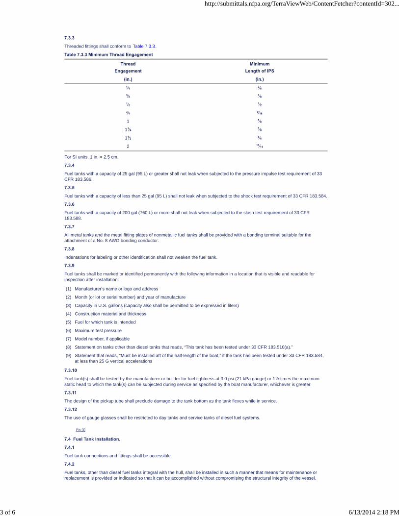
7.3.3
Threaded fittings shall conform to Table 7.3.3.
Table 7.3.3 Minimum Thread Engagement
ThreadEngagement
MinimumLength of IPS
(in.) (in.)1⁄4 3⁄8
3⁄8 3⁄8
1⁄2 1⁄2
3⁄4 9⁄16
1 5⁄8
11⁄4 5⁄8
11⁄2 5⁄8
2 11⁄16
For SI units, 1 in. = 2.5 cm.
7.3.4
Fuel tanks with a capacity of 25 gal (95 L) or greater shall not leak when subjected to the pressure impulse test requirement of 33CFR 183.586.
7.3.5
Fuel tanks with a capacity of less than 25 gal (95 L) shall not leak when subjected to the shock test requirement of 33 CFR 183.584.
7.3.6
Fuel tanks with a capacity of 200 gal (760 L) or more shall not leak when subjected to the slosh test requirement of 33 CFR183.588.
7.3.7
All metal tanks and the metal fitting plates of nonmetallic fuel tanks shall be provided with a bonding terminal suitable for theattachment of a No. 8 AWG bonding conductor.
7.3.8
Indentations for labeling or other identification shall not weaken the fuel tank.
7.3.9
Fuel tanks shall be marked or identified permanently with the following information in a location that is visible and readable forinspection after installation:
(1) Manufacturer's name or logo and address
(2) Month (or lot or serial number) and year of manufacture
(3) Capacity in U.S. gallons (capacity also shall be permitted to be expressed in liters)
(4) Construction material and thickness
(5) Fuel for which tank is intended
(6) Maximum test pressure
(7) Model number, if applicable
(8) Statement on tanks other than diesel tanks that reads, “This tank has been tested under 33 CFR 183.510(a).”
(9) Statement that reads, “Must be installed aft of the half-length of the boat,” if the tank has been tested under 33 CFR 183.584,at less than 25 G vertical accelerations
7.3.10
Fuel tank(s) shall be tested by the manufacturer or builder for fuel tightness at 3.0 psi (21 kPa gauge) or 11⁄2 times the maximumstatic head to which the tank(s) can be subjected during service as specified by the boat manufacturer, whichever is greater.
7.3.11
The design of the pickup tube shall preclude damage to the tank bottom as the tank flexes while in service.
7.3.12
The use of gauge glasses shall be restricted to day tanks and service tanks of diesel fuel systems.
7.4 Fuel Tank Installation.
7.4.1
Fuel tank connections and fittings shall be accessible.
7.4.2
Fuel tanks, other than diesel fuel tanks integral with the hull, shall be installed in such a manner that means for maintenance orreplacement is provided or indicated so that it can be accomplished without compromising the structural integrity of the vessel.
http://submittals.nfpa.org/TerraViewWeb/ContentFetcher?contentId=302...
3 of 6 6/13/2014 2:18 PM
PIs [1]
7.4.3
Fuel tanks shall be installed in a manner that prevents permanent deformation.
7.4.4
Fuel tanks shall be installed in a manner that provides immobilization to the extent practicable.
7.4.5
Nonmetallic fuel tanks that expand dimensionally after exposure to fuel shall comply with the following:
(1) They shall be installed in accordance with the fuel tank manufacturer's instructions
(2) The fuel tank manufacturer's instructions shall indicate the installation clearances required for the tank in diagram form.
(3) They shall be provided with a warning label that contains at a minimum the following informational elements:
CAUTION:To prevent hull and tank damage due to expansion of the tank while in service, installation shall be inaccordance with the manufacturer's instructions.
7.4.6
Contact between metallic fuel tanks and other structures shall be limited to necessary structural supports and shall permit freecirculation of air.
7.4.7
Abrasive surfaces and absorbent surfaces of tank supports and braces shall be insulated effectively from contact with tank surfacesby a nonabrasive and nonabsorbent material.
7.4.8
Aluminized steel tanks of thicknesses less than 0.0785 in. (2 mm) shall be installed above the cockpit deck or above deck if there isno clearly defined cockpit.
7.4.9
Nonferrous and nonmetallic fuel tanks shall be permitted to be foamed in place if they comply with the requirements of 33 CFR183.516. (See 7.4.5.)
7.4.10
Fuel tanks shall not be installed above the engine and shall not be installed above sources of ignition.
7.4.11
Fuel tank(s) shall not support a deck, a bulkhead, or other structure.
7.5 Fuel Lines, Fittings, and Related Accessories.
7.5.1 General.
7.5.1.1
For the purposes of Section 7.5, fuel lines shall mean all pipes, tubing, or hose that conduct fuel from the deck fill plate to theengine connection.
7.5.1.2
For the purposes of Section 7.5, related accessories shall include any attachments to fuel lines such as valves, filters, strainers,pumps, and connecting fittings.
7.5.1.3
All fuel tank fittings shall be galvanically compatible with the fuel tank material.
7.5.1.4
Copper-bearing fittings shall be isolated from aluminum tanks by a galvanic barrier including, but not limited to, a 300 seriesstainless steel fitting.
7.5.1.5
Flexible nonmetallic fuel hose shall be one of the following:
(1) USCG Type A-1 or A-1-15 or Type A-2 hose where 21⁄2-minutes minimum fire resistance is required
(2) USCG Type A-1 or A-1-15, Type A-2, Type B-1 or B-1-15, or Type B-2 hose where 21⁄2-minutes minimum fire resistance is notrequired (see 7.1.5)
7.5.1.6
Fuel lines, connections, and accessories shall be accessible.
7.5.1.7* Plastic Components.
7.5.1.7.1
Plastic pipe and plastic fittings shall not be used in fuel distribution lines, vent lines, and fill lines unless permitted by 7.5.1.7.2 or7.5.1.7.3. (See 7.1.5.)
7.5.1.7.2
Components of deck fill fittings, vent fillings, carburetor fittings, fuel pump fittings, and fuel filter fittings shall be permitted to be ofplastic.
7.5.1.7.3
Engineering-grade plastics, such as glass-reinforced nylons, shall be permitted to be used in fuel distribution lines, vent lines, andfill lines.
http://submittals.nfpa.org/TerraViewWeb/ContentFetcher?contentId=302...
4 of 6 6/13/2014 2:18 PM
7.5.1.8
Fuel lines shall be secured against movement or vibration by the use of noncombustible clips or straps without rough surfaces orsharp edges.
7.5.1.9
Clips and straps used to hold fuel lines in position to maintain anti-siphon protection shall be capable of withstanding a 21⁄2-minutefire test.
7.5.1.10
Gasoline-resistant sealing compound or tape shall be used in making up threaded pipe connections.
7.5.1.11
Where making flared tubing connections, the following criteria shall be met:
(1) Tubing shall be cut squarely and flared by tools designed for that purpose.
(2) Tubing shall be deburred prior to being flared.
(3) Copper tubing shall be annealed prior to being flared.
7.5.1.12 Outlets.
7.5.1.12.1
Outlets for drawing fuel from the system are prohibited unless permitted by 7.5.1.12.2.
7.5.1.12.2
Filter bowl plugs provided for the purpose of servicing only shall be permitted.
7.5.1.13 Manually Operated Valves.
7.5.1.13.1
Manually operated multiposition valves shall be required to indicate only their open and closed positions.
7.5.1.13.2
Manually operated stop valves shall be designed with positive stops in the open and closed positions.
7.5.2 Installation of Fill and Vent Pipes.
7.5.2.1
Fuel tank fill and vent pipes shall be located in the following manner:
(1) To prevent the escape of liquid and vapor overflow to the inside of the hull
(2) To provide protection from the flow of vapors escaping into the hull
7.5.2.2
No liquid fuel shall enter the boat from the fill due to an overflow rate of 5 gpm (19 L/min) for 5 seconds when the boat is in its staticfloating position.
7.5.2.3
The vent pipe shall terminate at least 15 in. (38 cm) from any hull opening.
7.5.2.4*
The vent shall be installed to minimize the intake of water without resisting the release of vapor.
7.5.2.5
Overflow from the vent at a rate of 2 gpm (7.7 L/min) shall not enter the boat.
7.5.2.6
The inside diameter of the fill pipe system shall be no less than 11⁄4 in. (3.2 cm) and shall have a hose diameter of no less than 11⁄2in. (3.8 cm).
7.5.2.7
The fuel fill shall be self-draining from the fuel fill inlet to the tank connection.
7.5.2.8
The fuel fill plate shall be identified by a permanent marking indicating the type of fuel.
7.5.2.9*
Bonding wire ends shall not be clamped between the fill pipes and the flexible tubing. (See 7.1.6.)
7.5.2.10
No blow-back of fuel through the fill fitting shall occur while filling at a rate of 9 gpm (35 L/min) and to a level of one-quarter to three-quarters of the capacity indicated by the tank label.
7.5.2.11
As installed in the boat, the vent pipe connection shall be at the highest point of the tank under conditions of normal trim.
7.5.2.12
The inside diameter at any location in the vent line system shall be not less than 7⁄16 in. (11 mm).
7.5.2.13
The fittings at the hull vent line opening shall be corrosion resistant.
http://submittals.nfpa.org/TerraViewWeb/ContentFetcher?contentId=302...
5 of 6 6/13/2014 2:18 PM
7.5.2.14
Each fuel tank vent system shall have a flame arrester that can be cleaned unless one of the following conditions is met:
(1) The vent system itself is a flame arrester.
(2) Metallic vent lines are used and serve as effective flame arresters.
7.5.2.15 Hose Clamps.
7.5.2.15.1
If a nonmetallic hose is used in the fill pipe system, it shall be secured tightly with a minimum of two corrosion-resistant metalclamps of 1⁄2 in. (12.7 mm) minimum width at each end of the hose.
7.5.2.15.2
Clamps depending solely on spring tension shall not be used to meet the requirements of 7.5.2.15.1.
7.5.3* Installation of Fuel Feed Lines and Accessories.
7.5.3.1*
Electric fuel supply pumps, other than priming pumps in outboard motor fuel systems, shall operate only under the followingconditions:
(1) The engine is operating.
(2) The cranking motor is energized.
(3) The supply pump is operated by a momentary switch for priming and is located either on or within 12 in. (30 cm) of the engine.
7.5.3.2
Hose installed on the pressure side of an electric fuel supply pump shall be USCG Type A-1 or A-1-15.
7.5.3.3
Fuel lines shall be run with as few connections as practicable.
7.5.3.4
Fuel lines that run over dry sections of the engine exhaust system shall be metallic and shall contain no joints, fittings, orcomponents other than at the point of termination.
7.5.3.5
Gasoline fuel distribution systems shall be provided with anti-siphon protection by at least one of the following methods:
(1) All parts of fuel distribution and return lines are installed above the level of the tank top from the tank to the carburetor inlet orits equivalent (e.g., throttle body, port fuel injection).
(2) All parts of fuel distribution and return lines are installed above the level of the tank top from the tank to a location where fuelleakage cannot enter the boat when the boat is in a static floating position.
(3) An anti-siphon device is installed at the tank withdrawal fitting, or along the line, with a rated siphon protection head and flowrate greater than required for the installation.
(4) An electrically operated valve is installed at the tank fitting, or along the line, that is to be energized open only when the engineignition switch is on and the engine is running, with a momentary-type override permitted to be used for starting.
(5)
(6) A manual shutoff valve shall be installed directly at the fuel tank connection, arranged to be readily accessible for operationfrom outside the compartment if the fuel tank top is located below the level of the carburetor inlet, the fuel line is rigid metal orUSCG Type A-1 or A-1-15 hose, a manual shutoff valve is installed at the fuel inlet connection to the engine, and the length ofthe fuel line from the tank outlet to the engine inlet is more than 12 ft (3.6 m).
7.5.3.6 Systems Without Anti-Siphon Protection.
7.5.3.6.1*
A readily accessible manual shutoff valve shall be installed on all fuel tanks directly at the tank connection where the fuel system iswithout anti-siphon protection.
7.5.3.6.2
If the fuel tank is located in a machinery space, a remotely operated means of closing the valve required in 7.5.3.6.1, withoutopening machinery spaces, shall be provided.
7.5.3.7
A flexible section, meeting the requirements of 7.5.1.5, shall be installed to separate the part of the fuel feed line secured to the hullmembers from the part of the fuel feed line secured to the engine.
7.5.3.8
The fixed fuel line shall be fastened to structures within 4 in. (10 cm) of the connection to the flexible section to secure againstvibration and movement.
* A manual shutoff valve is installed directly at the fuel tank connection, arranged to be readily accessible for operation fromoutside the compartment if the fuel tank top is located below the level of the carburetor inlet, the fuel line is rigid metal orUSCG Type A-1 or A-1-15 hose, and the length of the fuel line from the tank outlet to the engine inlet is no more than 12 ft (3.6m).
http://submittals.nfpa.org/TerraViewWeb/ContentFetcher?contentId=302...
6 of 6 6/13/2014 2:18 PM
NFPA 302®, Fire Protection Standard for Pleasure and Commercial Motor Craft, 2010 Edition
NFPA STANDARDS DEVELOPMENT SITEFIRST DRAFT REPORTClosing Date: February 22, 2013 NOTE: All Public Comment must be received by 5:00 pm EST/EDST on the published Closing Date.
Quick PrintChapter 8 Cooking, Heating, and Auxiliary Appliances
8.1* General.
8.1.1 Instructions.
8.1.1.1
Printed instructions for proper installation, operation (including refueling, where applicable), and maintenance shall be provided witheach appliance.
8.1.1.2
The instructions required in 8.1.1.1 shall include the following information:
(1) The hazards associated with appliance air consumption
(2) Installer information regarding the proper display of a warning label
8.1.2
Appliances using gasoline in liquid or solid form for priming or fuel shall be prohibited.
8.1.3*
The design and installation of appliances shall address the air consumption of the appliances and the venting of exhaust products.
8.1.4
An appliance shall be mounted in accordance with the manufacturer's instructions.
8.1.5
Appliances shall be fastened securely when in use or stored.
8.1.6
A burner system shall meet the following criteria:
(1) It shall be capable of operation without creating a fire hazard during periods of boat pitch and roll at angles up to 30 degreesfrom horizontal in any direction sustained for 15 seconds.
(2) It shall be capable of continuous operation at angles of heel up to 30 degrees.
8.1.7 Label.
8.1.7.1
A durable and permanently legible label shall be provided detailing the proper operation and any unique hazards of the appliance.
8.1.7.2
The label required in 8.1.7.1 shall be mounted in plain view of the appliance operator.
8.1.8
Appliance operating controls shall be located to reduce the likelihood of injury from burners or elements while in use.
8.1.9 Glow Plugs and Pilot Lights.
8.1.9.1
Appliances with automatic igniter glow plugs or continuously lighted pilot lights for burner ignition shall be prohibited unlesspermitted by 8.1.9.2 or 8.1.9.3.
8.1.9.2
Automatic igniter glow plugs in appliances using sealed combustion chambers shall be permitted.
8.1.9.3
An oven control flame that operates only when the stove is in use shall be permitted.
8.1.10
Appliances shall be marked or identified permanently with the following information in a location visible after installation:
(1) Manufacturer's name or trademark
(2) Model number
(3) Serial number (if applicable)
(4) Fuel/energy used
(5) Maximum power consumption in kW when operating at capacity
8.2 Cooking Appliance Installation.
http://submittals.nfpa.org/TerraViewWeb/ContentFetcher?contentId=302...
1 of 10 6/13/2014 2:18 PM

PIs [1] FR-20 Hide Legislative
PIs [1] FR-22 Hide Legislative
8.2.1
Exposed materials and finishes within 24 in. (61 cm) of heat-generating surfaces of appliances shall have a flame spread index ofnot more than 75 as determined when tested in accordance with NFPA 255 , Standard Method of Test of Surface BurningCharacteristics of Building Materials . ASTM E84, Standard Test Method of Test for Surface Burning Characteristics of BuildingMaterials .
8.2.2
Fabrics located above and within 39 in. (1 m) of a galley stove top, used for decorative or other purposes, shall be flame resistant inaccordance with shall meet the flame propagation performance criteria contained in Test Method 1 or Test Method 2, asappropriate, of NFPA 701, Standard Methods of Fire Tests for Flame Propagation of Textiles and Films.
8.2.3
With the appliance installed, the temperature of vertical combustible surfaces below and surrounding heat-generating surfaces shallnot rise more than 150°F (65°C) above the compartment's ambient temperature when using the temperature test of ANSI/UL 858,Standard for Safety Household Electric Ranges.
8.3 Coal, Charcoal, and Wood-Burning Appliances.
8.3.1
Appliances that burn solid fuel shall not be installed in gasoline-powered boats.
8.3.2
Installed stoves shall be mounted by one of the following methods:
(1) On a noncombustible base (preferably hollow tile)
(2) On legs providing a clearance of at least 5 in. (13 cm) between the stove bottom and the deck, and the deck insulated with anoncombustible material or sheathing
8.3.3 Stove Clearance.
8.3.3.1
The sides and backs of uninsulated stoves shall have a minimum clearance of 9 in. (23 cm) from the exposed materials andfinishes, which shall meet the requirements of 8.2.1, or shall be separated by fire-resistant thermal insulation.
8.3.3.2
The sides and backs of insulated stoves shall have a minimum clearance from the exposed materials and finishes as specified bythe manufacturer.
8.3.4 Smoke Pipe and Stack Clearance.
8.3.4.1
Single-wall smoke pipes and stacks on decks not equipped with water irons shall have a minimum clearance of 9 in. (23 cm) fromcombustible materials, including painted surfaces, or shall be separated by fire-resistant thermal insulation.
8.3.4.2
Listed and labeled double- or triple-wall smoke pipes and stacks on decks not equipped with water irons shall be installed with aminimum clearance from combustible materials, including painted surfaces, specified by the manufacturer.
8.3.5
Permanently installed solid-fuel burning appliances, other than solidified-alcohol galley stoves and exterior mounted grills, shall beequipped with a double- or triple-wall smoke pipe or stack that shall terminate above deck, and with smoke heads designed tominimize water entry, spark emission, and backdraft.
8.3.6
Where double- or triple-wall smoke pipe or stacks are installed, they shall meet the requirements of ANSI/UL 103, Standard forSafety Factory-Built Chimneys for Residential Type and Building Heating Appliances, and installed in accordance with thespecifications of the manufacturer.
8.3.7
Charcoal stored on the boat shall be kept dry and stored in a closed, dry metal container.
8.4 Liquid Fuel Appliances Excluding Liquefied Petroleum Gas (LPG) Appliances.
8.4.1
Both pressure-fed and gravity-fed burners shall be permitted.
8.4.2 Fuel Tanks.
8.4.2.1
Fuel supply tanks shall be constructed of corrosion-resistant metal or of metal having a corrosion-resistant finish or coating.
8.4.2.2 Pressurized Tanks.
http://submittals.nfpa.org/TerraViewWeb/ContentFetcher?contentId=302...
2 of 10 6/13/2014 2:18 PM

8.4.2.2.1
Appliances with pressurized liquid fuel tanks that are integral with an appliance shall comply with the following criteria:
(1) Tanks shall withstand an internal pressure of four times the relief valve setting or 100 psi (700 kPa gauge), whichever isgreater.
(2) Tank shall be shielded or insulated so that, under continuous operation at maximum heat, the pressure in the tank shall notexceed 50 percent of the relief valve setting.
(3) The complete system shall be tested up to the pressure of the relief valve setting.
8.4.2.2.2
Pressure tanks not integral with an appliance shall comply with the following criteria:
(1) Tanks shall be able to withstand a test pressure of at least 100 psi (700 kPa gauge) or twice the appliance relief valve setting,whichever is greater.
(2) Tanks shall be secured rigidly in an accessible location that permits convenient filling and pump operation.
8.4.2.2.3
Pressurized fuel tanks shall be equipped with relief valves.
8.4.2.3 Gravity Tanks.
8.4.2.3.1
Gravity tanks installed in the compartment with the appliance shall be located or shielded so that, when installed and undercontinuous operation at maximum heat output, the fuel temperature shall not rise more than 25°F (14°C) above the compartmenttemperature.
8.4.2.3.2
Gravity tanks shall have a capacity no more than 2.1 gal (8 L), unless the tank meets the requirements of Section 7.2 and iscapable of withstanding a pressure of 3 psi (21 kPa gauge).
8.4.2.3.3
Non-integral gravity tanks shall have provisions for filling and venting at a distance of at least 39 in. (1 m) from open flame unlessseparated by a vaportight partition or bulkhead.
8.4.2.3.4
Where appliances burning liquid fuels have remote gravity tanks, provisions shall be made to relieve any excess pressure in the fuelline between the tank shutoff valve and the burner valve.
8.4.2.4
A readily accessible shutoff valve, not integral with the appliance, shall be installed near gravity tanks and at or on all non-integralpressure tanks.
8.4.2.5
Where a valve is required by 8.4.2.4, the valve shall close against fuel flow and shall clearly indicate the closed and open positions.
8.4.2.6
Liquid fuel supply lines from non-integral tanks shall be installed as a continuous run from the shutoff valve at the tank to theappliance or to the flexible section located immediately before a gimbaled stove.
8.4.2.7
Flexible liquid fuel supply hose sections shall be compatible with the fuel used.
8.4.2.8*
The fill openings for non-integral fuel tanks shall be identified to indicate the type of fuel to be used with the system, and the word“fuel” shall not be used alone.
8.4.2.9
Liquid-fuel priming pans or troughs shall be secured to the burner or generator so that their mutual function is maintained.
8.4.2.10
A liquidtight, nonflammable drip pan at least 3⁄4 in. (19 mm) deep shall be provided below all burners and shall be readily accessiblefor cleaning.
8.4.2.11
Appliances with integral tanks supplying fuel by gravity or pressure shall display a permanently affixed, legible warning label thatcontains at a minimum the following informational elements:
CAUTION:Fire and explosion hazard; severe burns.Before filling, turn off burners.
8.4.2.12
Unpressurized stoves with fuel held in absorbent matter and designed with a fuel container removed for filling shall display apermanently affixed, legible label that contains at a minimum the following informational elements:
CAUTION:Fire and explosion hazard; severe burns.Before filling, turn off all stove burners.Remove fuel container from stove.Fill fuel container away from stove.Follow filling instructions provided.
http://submittals.nfpa.org/TerraViewWeb/ContentFetcher?contentId=302...
3 of 10 6/13/2014 2:18 PM
8.4.3
If solidified alcohol is used as stove fuel, the container shall be secured on a fixed base to prevent sliding or overturning due to asudden roll of the vessel.
8.4.4
Stacks and stoves shall comply with the applicable requirements of Section 8.3.
8.4.5 Sealed Combustion Chamber Heaters.
8.4.5.1
Sealed combustion chamber heaters that burn fuel oil shall be permitted to be used if they are designed to provide completeseparation of the combustion system from the atmosphere in the boat.
8.4.5.2
A combustion air inlet and flue gas outlet shall be provided as integral parts of the appliance.
8.4.6*
Means shall be provided on stove-top cooking surfaces to prevent both deep and shallow cooking utensils from sliding across or offthe stove.
8.4.7
Oven doors shall be provided with a means to prevent their unintentional opening due to the force of sliding food and utensils.
8.4.8
A permanent, legible label shall be affixed in a conspicuous location on or adjacent to fuel burning stoves or ranges and shallcontain at a minimum the following informational elements:
CAUTION:Open-flame cooking appliances consume oxygen. Lack of oxygen can cause asphyxiation or death. Maintainopen ventilation when appliance is in use. Do not use appliances for comfort heating.
8.4.9
Stove operating controls shall be located to be easily accessible and to minimize possible injury from burners or elements while inuse.
8.4.10
The operation of controls shall not require reaching over or across burners or heated elements.
8.5* Liquefied Petroleum Gas (LPG) and Compressed Natural Gas (CNG) Systems for Permanently Installed Appliances.
8.5.1
The installation for use and storage of stoves with attached (integral) LPG containers of more than 8 oz (230 g) capacity weight ofgas shall be prohibited in accommodation spaces in the boat interior.
8.5.2
LPG and CNG appliances, other than the appliances addressed in 8.5.3, shall be permanently installed.
8.5.3
Appliances employing integral butane cylinders containing no more than 8 oz (230 g) of fuel, and that comply with 8.5.14.9, shallnot be required to be permanently installed.
8.5.4
Components of LPG systems subject to cylinder pressure shall have a rated working pressure of no less than 250 psi (1725 kPagauge).
8.5.5
Components of CNG systems subject to cylinder pressure shall have a working pressure of no less than 133 percent of themaximum fill pressure of the cylinder.
8.5.6* Ignition Protection of Electrical Devices.
8.5.6.1
Electrical devices on boats equipped with LPG or CNG systems, which can function or cycle on and off automatically without thepresence of a person and that are located below the main deck, shall be provided with ignition protection in accordance with UL1500, Standard for Safety Ignition-Protection Test for Marine Products, if located in compartments other than those in 8.5.6.2 and8.5.6.3, that contain LPG or CNG appliances, cylinders, fittings, valves, or regulators.
8.5.6.2
The requirements of 8.5.6.1 shall not apply to electrical devices in accommodation spaces.
8.5.6.3
The requirements of 8.5.6.1 shall not apply to electrical devices in open compartments having at least 15 in.2 (97 cm2) of openarea per cubic foot of net compartment volume exposed to the open atmosphere outside the craft.
8.5.7
Systems shall use cylinders of the vapor withdrawal type.
8.5.8
Cylinders designed or installed to admit LPG into any other part of the system shall be prohibited.
8.5.9 Labels.
http://submittals.nfpa.org/TerraViewWeb/ContentFetcher?contentId=302...
4 of 10 6/13/2014 2:18 PM

8.5.9.1
With each LPG or CNG system installed on a boat, at least two labels in accordance with 8.1.1 and 8.1.7 shall be installed andinclude the following:
(1) The signal word “WARNING”
(2) The introductory statement “To Avoid Fire and Explosion”
8.5.9.2
Labels at appliances shall include the statement, “This system is designed for use with (insert LPG or CNG) only. Do not connect(insert LPG or CNG) to this system.”
8.5.9.3
Labels at containers shall include the following instructions where no leak detection device is installed:
(1) Close container valves when the boat is unattended and in case of a leak or fire.
(2) Close all appliance valves before opening container valves.
(3) Always apply the source of ignition to the burner before opening the burner valve.
(4) Mark container locker “For storage of (insert LPG or CNG) containers only.”
(5) Keep valves closed and plugged on empty or unconnected containers.
(6) Test the system for leakage whenever the system is used, when the system is serviced, or when the container is changed asfollows:
(a) With the appliance valves closed and all other valves open, note the pressure on the gauge.
(b) Close the container valve.
(c) Ensure that the pressure remains constant for at least 5 minutes.
(d) If the pressure drops, locate the leakage by application of a soapy water solution at all connections.
(e) Repeat the test for each container in multicontainer systems.
(f) Never use flame or soap containing ammonia to check for leaks.
8.5.9.4
Labels at containers shall include the instructions of 8.5.9.3 modifying 8.5.9.3(6) as appropriate if a leak detection device isinstalled.
8.5.9.5
On boats that have gasoline engines, the labels shall also contain at a minimum the following informational elements:
CAUTION:Avoid fire or explosion. Open-flame appliances can ignite gasoline vapor, causing fire or explosion.Turn off all open-flame appliances while fueling.
8.5.9.6
The required warning labels shall be installed in plainly visible locations on the outside of each container enclosure and adjacent toeach consuming appliance.
8.5.10 Containers.
8.5.10.1
Containers shall be constructed, tested, marked, maintained, requalified for continued service, and refilled in accordance with oneof the following:
(1) U.S. Department of Transportation (DOT) regulations for containers in LPG or CNG service
(2) Equivalent specifications or regulations to those in 8.5.10.1(1) and acceptable to the authority having jurisdiction
8.5.10.2
Containers shall be withdrawn from service under the following conditions:
(1) When they leak
(2) When corrosion, denting, bulging, or other evidence of rough usage exists to the extent that the container has been weakened
(3) When exposed to fire
8.5.11 Container Valves and Safety Relief Devices.
8.5.11.1
Each container other than nonrefillable containers shall have a manually operated shutoff valve installed directly into the containeroutlet opening that can be operated without the use of tools.
8.5.11.2
Where the container valve is not readily accessible from within the vicinity of the appliance, a readily accessible manual orelectrically operated (solenoid) shutoff valve in addition to the valve required by 8.5.11.1 shall be installed and comply with thefollowing:
(1) The valve shall be operable from within the vicinity of the appliance(s).
(2) The valve shall be installed in the low- or high-pressure fuel line at the fuel supply.
8.5.11.3
The location of the shutoff valve or control shall not require reaching across flame- or heat-generating surfaces for operation.
http://submittals.nfpa.org/TerraViewWeb/ContentFetcher?contentId=302...
5 of 10 6/13/2014 2:18 PM
8.5.11.4
All containers shall be provided with safety relief devices as required by DOT regulations or equivalent regulations.
8.5.11.5
LPG container valves and safety relief devices shall have direct connection with the vapor space of the cylinder.
8.5.11.6
In addition to the valve required by 8.5.11.1, a multiple cylinder system shall be provided with a manual positive shutoff valve orautomatic check valve at the cylinder manifold such that each cylinder shall be isolated from the pressure feedback from othercylinders.
8.5.11.7
All relief valves shall discharge to the open atmosphere at a point at least 2 ft (0.6 m) from any opening to any of the following:
(1) Cabin
(2) Hull interior
(3) Engine exhaust terminus
8.5.11.8
Valve outlets on containers shall be equipped with a plug or cap for thread protection and to keep out foreign material.
8.5.11.9
Whenever the container is not connected for use, the plug or cap required by 8.5.11.8 shall be in place and the container valveshall be kept tightly closed.
8.5.12 Reducing Regulators.
8.5.12.1
Each system shall be provided with a pressure-regulating device to deliver gas to the distribution piping that is specifically designedfor the type of gas being used.
8.5.12.1.1
The regulating device required by 8.5.12.1 shall be adjusted to deliver gas at a pressure no more than 14 in. (36 cm) water column,approximately 0.735 psi (5.0 kPa gauge), for LPG systems.
8.5.12.1.2
The regulating device required by 8.5.12.1 shall be adjusted to deliver gas at a pressure no more than 6 in. (15 cm) water column,approximately 0.22 psi (1.5 kPa gauge), for CNG systems.
8.5.12.2
A low-pressure relief valve shall be integral with each regulator and shall discharge at between 1.7 and 3 times the deliverypressure of the regulator.
8.5.12.3
The relief valve vent outlet shall be located and designed to prevent water from entering the discharge system.
8.5.12.4*
Each reducing regulator shall be fitted with a pressure gauge on the high-pressure side, and a leak detector shall be permitted to beused in addition to the gauge.
8.5.12.5
Each CNG system shall be supplied with a high-flow check valve located on the container pressure side of the regulating device.
8.5.12.6
The high-flow check valve required by 8.5.12.5 shall actuate and control gas flow through the vent or vent systems to theatmosphere in the event of regulator malfunction and shall maintain this gas flow within designed pressure limits of the vent system.
8.5.12.7
Relief high-flow restrictor vent outlets shall conform to the requirements of 8.5.11.7.
8.5.12.8
CNG pressure regulators shall be connected directly to the container shutoff valve, using one CGA series 350 connection.
8.5.13 Piping, Hose, and Fittings — LPG and CNG Distribution Systems.
8.5.13.1 Piping.
8.5.13.1.1
Low-pressure distribution piping between the regulator and appliances shall be galvanically compatible for a marine environment.
8.5.13.1.2
Piping shall be copper tubing of standard Type K, Type L, or equivalent.
8.5.13.1.3
Piping shall have a minimum wall thickness of at least 0.032 in. (0.8 mm) nominal.
8.5.13.1.4
Copper tubing in CNG systems shall be internally tinned.
8.5.13.2 Flexible Hose.
8.5.13.2.1 Hose Specifications.
http://submittals.nfpa.org/TerraViewWeb/ContentFetcher?contentId=302...
6 of 10 6/13/2014 2:18 PM

8.5.13.2.1.1
LPG flexible distribution hose shall meet the requirements of UL 21, Standard for Safety LP-Gas Hose.
8.5.13.2.1.2
CNG flexible hose shall meet the requirements of NFPA 52, Vehicular Gaseous Fuel Systems Code.
8.5.13.2.2
Flexible hose shall be labeled for the fuel being used.
8.5.13.3
Connecting fittings shall be accessible.
8.5.13.4
Metallic connections, if soldered, shall be soldered or brazed with a material having a melting point exceeding 840°F (450°C).
8.5.13.5
Distribution lines shall be protected from physical damage and shall be accessible for inspection.
8.5.13.5.1
Lines shall be secured against vibration.
8.5.13.5.2
Lines shall be protected from abrasion wherever they pass through decks or bulkheads.
8.5.13.5.3
Each appliance shall be served by a separate low-pressure regulated supply line, which shall originate inside the locker orprotective enclosure.
8.5.13.5.4
Flexible supply hose shall have permanently attached end fittings, such as a swaged sleeve or a sleeve and threaded insert.
8.5.13.6
Metal tube or piping shall be connected by means of flare fittings or other fittings designed for resistance to loosening due tovibration or movement, and shall not be connected using metal-to-metal compression sleeve-type fittings.
8.5.13.7
Flexible hose sections connecting appliances to their fuel supply shall be nonmetallic.
8.5.13.8
Flexible metallic connectors shall not be used to connect appliances to their fuel supply.
8.5.13.9
A flexible hose section shall be installed to allow the free swing of gimbaled stoves without stress to end fittings at expectedextremes of travel.
8.5.13.10
Fuel supply lines, except for flexible hose installed to connect tube or piping to a device, shall be continuous lengths of tubing,piping, or hose to the appliance from one of the following:
(1) Regulating device
(2) Solenoid valve
(3) Leak detector (if installed)
(4) Manifold
8.5.13.11
Metallic fuel supply lines shall not be used for electrical grounding or bonding.
8.5.14 Appliances.
8.5.14.1
Appliances with automatic igniters for burner ignition, other than those with sealed combustion chambers, are prohibited.
8.5.14.2
All gas-fueled appliances, other than stoves with integral gas cylinders not exceeding 8 oz (230 g) capacity, shall incorporate aflame failure device on each burner or oven control flame to prevent gas flow if flame is not present.
8.5.14.3
Cabin space heaters, water heaters, gas-fueled refrigerators, and air conditioners shall be of the sealed combustion chamber type,designed to provide complete separation of the combustion system from the atmosphere in the boat.
8.5.14.4
A combustion air inlet and flue gas outlet shall be provided as integral parts of the appliances identified in 8.5.14.3.
8.5.14.5
Burner controls shall be equipped or designed to provide a push-turn or other two-phase operation when moved from the OFFposition to the ON position.
8.5.14.6
Cooking appliances shall meet the combustion requirements of ANSI Z21.57, Recreational Vehicle Cooking Gas Appliances.
http://submittals.nfpa.org/TerraViewWeb/ContentFetcher?contentId=302...
7 of 10 6/13/2014 2:18 PM

8.5.14.7
A permanent, legible label shall be affixed in a conspicuous location on or adjacent to appliances not having sealed combustionchambers that shall contain at a minimum the following informational elements:
CAUTION:Open-flame appliances consume oxygen.Lack of oxygen can cause asphyxiation or death.Maintain open ventilation when appliance is in use.
8.5.14.8
Means shall be provided on stove top cooking surfaces to prevent both deep and shallow cooking utensils from sliding across or offthe stove at boat pitch or roll up to 30 degrees horizontal in any direction.
8.5.14.9 Cooking Equipment with Integral Fuel Cylinders.
8.5.14.9.1
Printed instructions for proper installation, operation, fuel storage, refueling, and maintenance shall be provided with each stove.
8.5.14.9.2
Fuel cylinders with a capacity of 8 oz (230 g) or less shall be DOT approved 2P/2Q cylinders with rim vent release.
8.5.14.9.3
Where used in the boat interior, stoves shall be secured in a designated location with a positive means of mechanical retention andthe installation shall meet the requirements of Section 8.2.
8.5.14.9.4
A means shall be provided for storing all unattached fuel cylinders in a protected, self-draining location on the exterior of the boat sothat vapors can flow overboard only.
8.5.14.10
The appliance shall have a label that indicates the required location of the device relative to all combustible surfaces and thatidentifies the type of fuel to be used with the appliance.
8.5.15 Location and Installation.
8.5.15.1
LPG and CNG containers, regulating devices, and safety equipment shall meet the following criteria:
(1) They shall be rigidly secured.
(2) They shall be readily accessible for operation of valves and testing for leakage.
(3) They shall be protected by a dedicated locker unless permitted otherwise by 8.5.15.2.1 or 8.5.15.2.2.
8.5.15.2 Dedicated Locker.
8.5.15.2.1
Containers shall not be required to be installed in a dedicated locker where located on open decks such that escaping vapor cannotaccumulate in a cockpit or enclosed spaces, provided regulators, tank valves, and fittings are protected against mechanical damageby a vented housing, shield, or guard.
8.5.15.2.2
A CNG container shall not be required to be installed in a dedicated locker in CNG systems with a single container connected to the
system having a capacity to hold 100 ft3 or less of gas, when the gas is at 14.5 psi and 70°F.
8.5.15.2.3
A protective dedicated locker shall meet the following criteria:
(1) It shall be located above the waterline.
(2) It shall be vaportight to the hull interior.
(3) It shall be provided with a means to latch its cover.
(4) It shall be vented to the atmosphere.
(5) It shall be located so that, with its cover open or closed, escaping vapor cannot reach the bilges, machinery spaces,accommodations, or other enclosed spaces.
8.5.15.2.4
An LPG container locker shall be vented from the bottom by means of a vent pipe that meets the following criteria:
(1) The vent pipe shall be of at least 1⁄2 in. (13 mm) internal diameter.
(2) The vent pipe shall lead outboard.
(3) The vent pipe shall be without pockets that can trap water.
(4) The vent pipe shall pass through the hull above the waterline and at a point lower than the locker bottom.
(5) The vent pipe opening shall be at least 2 ft (0.6 m) distant from, and not directly above, any hull opening, including the engineexhaust.
8.5.15.2.5
Compartments and lockers in which CNG cylinders are stored shall have a ventilation opening located above the level of thecylinder of at least 1⁄2 in. (13 mm) internal diameter.
http://submittals.nfpa.org/TerraViewWeb/ContentFetcher?contentId=302...
8 of 10 6/13/2014 2:18 PM
8.5.15.3
Installation of gas equipment in lockers or housing shall be such that, when the means of access to the lockers or housing is open,the container valves can be conveniently and quickly operated and the system pressure gauge dials are fully visible.
8.5.15.4
Lockers or housings for gas equipment shall not be used for storage of any other equipment, nor shall quick access to the gassystem be obstructed in any way.
8.5.15.5
Provisions for storage of unconnected reserve containers, filled or empty, shall be the same as required for containers in use.
8.5.15.6* Leakage Tests.
8.5.15.6.1
After installation, distribution tubing shall be tested prior to its connection to the regulator and appliance using an air pressure of notless than 5 psi (34.5 kPa gauge) above ambient.
8.5.15.6.2
The container valve shall be tested for leakage at its outlet and at its connection to the container by application of a soapy watersolution prior to connection of the system.
8.5.15.6.3
After the tests in 8.5.15.6.1 and 8.5.15.6.2, and when appliances and high-pressure equipment have been connected, the entiresystem shall be subjected to the following test:
(1) With appliance valves closed, solenoid valve or master shutoff valve at the appliance open, and one container valve open,note the pressure on the gauge.
(2) Close the container valve.
(3) Ensure pressure remains constant for at least 5 minutes.
(4) If the pressure drops, locate the leakage by application of soapy water solution at all connections.
8.5.15.6.4
Flame shall not be used to check for leaks.
8.5.15.7
CNG cylinders shall not be installed in compartments containing an internal combustion engine.
8.5.15.8
CNG cylinder storage compartments shall not have openings that communicate with the engine space above the level of thepressure regulator.
8.6 Service Water Heating Units and Cabin Heaters.
8.6.1
Vent stacks shall meet the following criteria:
(1) They shall lead to the atmosphere.
(2) They shall be equipped with an effective device for preventing flame extinguishment or flareback from backdraft and entranceof rain or spray.
8.6.2
Dampers shall not be installed in vent stacks.
8.7 Lamps.
8.7.1
Gasoline shall not be used for fuel.
8.7.2
Oil lamps shall have metal bodies and shall be hung in gimbals.
8.7.3
Oil lamps shall not be located directly over galley stoves or heating units.
8.7.4
Metal shields shall be secured above chimneys.
8.8 Electric Stoves.
8.8.1
Electric stoves shall meet the requirements of ANSI/UL 858, Standard for Safety Household Electric Ranges.
8.8.2
Electric stoves equipped with a lid or cover shall incorporate an automatic power disconnect switch that turns off all surface burnerswhen the lid or cover is lowered over the heating elements.
8.8.3
Electric stoves shall have a light indicating when one or more heating elements are energized.
8.8.4
Electric stoves shall be installed in accordance with the manufacturer's instructions.
http://submittals.nfpa.org/TerraViewWeb/ContentFetcher?contentId=302...
9 of 10 6/13/2014 2:18 PM

8.9 Portable Electric Heaters.
8.9.1
Portable heaters shall be UL listed.
8.9.1.1
Portable heaters shall be designed to operate on 120 VAC current.
8.9.1.2
Portable heaters shall not be rated at more than 5000 BTUH.
8.9.2
Portable heaters shall be used on boats only when attended.
8.10 Portable Dehumidifiers.
8.10.1
Portable dehumidifiers shall meet the requirements of UL 474, Standard for Dehumidifiers, and be so listed.
8.10.1.1
Portable dehumidifiers shall be designed to operate on 120 VAC current.
8.10.1.2
Portable dehumidifiers shall draw no more than 9 amperes at maximum capacity.
8.10.2
Portable dehumidifiers may be permitted to operate unattended only if connected to a dedicated outlet and the shore power inletconnection has been physically examined within the last month.
http://submittals.nfpa.org/TerraViewWeb/ContentFetcher?contentId=302...
10 of 10 6/13/2014 2:18 PM
NFPA 302®, Fire Protection Standard for Pleasure and Commercial Motor Craft, 2010 Edition
NFPA STANDARDS DEVELOPMENT SITEFIRST DRAFT REPORTClosing Date: February 22, 2013 NOTE: All Public Comment must be received by 5:00 pm EST/EDST on the published
Quick Print
PIs [1]
Chapter 9* Electrical Systems Under 50 Volts
9.1 Scope.
9.1.1
The standards and practices of this chapter shall apply to the design and installation of direct current (dc) electricalsystems on boats that operate at potentials of 50 volts or less except for the systems addressed in 9.1.2.
9.1.2
The standards and practices of this chapter shall not apply to any wire permanently attached to an outboard engineand extending not more than 72 in. (183 cm) from the outboard engine.
9.2 General Requirements.
9.2.1 Conductor Length Measurement.
All lengths for conductors shall be measured along the conductors.
9.2.2* Two-Wire System.
9.2.2.1
Branch circuits shall be of the two-wire type and shall use insulated conductors to and from each item of equipmentunless permitted otherwise by 9.2.2.4 or 9.2.2.5.
9.2.2.2
The feed and return wires for the circuits of 9.2.2.1 shall be run together from the power source to the equipment.
9.2.2.3
If a common return is used for the circuits of 9.2.2.1, it shall be of equal wire gauge to the panelboard feeder.
9.2.2.4
The electrical system on a propulsion or auxiliary engine shall be permitted to be of the one-wire type, with the negativeside of the system connected directly to the engine block.
9.2.2.5
The accessory negative bus of an outboard engine shall be permitted to be connected to the battery.
9.2.3 Return Circuit.
A metal hull, bonding conductor, or grounding conductor shall not be used as a return circuit unless permitted otherwiseby Section 9.11.
9.2.4 Grounded Systems.
If one side of a two-wire dc system is connected to ground, it shall be the negative side, and the system shall bepolarized.
9.2.5 Multiple Engine Installation.
9.2.5.1
If a boat has more than one inboard propulsion or auxiliary engine, grounded cranking motor circuits shall beconnected to each other by a common conductor that can carry the starting current of each of the grounded crankingmotor circuits.
9.2.5.2
Outboard engines shall be connected at the battery negatives.
9.2.6 Crossover (Parallel) Cranking Motor Circuits.
9.2.6.1
In multiple inboard engine installations (including auxiliary generators) with crossover (parallel) cranking motorsystems, the engines shall be connected together with a cable except for where the installation uses ungrounded dcelectrical systems.
9.2.6.2
The cable required by 9.2.6.1 shall be large enough to carry the cranking motor current of the largest cranking motor.
http://submittals.nfpa.org/TerraViewWeb/ContentFetcher?contentId=302...
1 of 15 6/13/2014 2:19 PM
9.2.6.3
The cable required by 9.2.6.1 and its terminations shall be in addition to, and independent of, any other electricalconnections to the engines, including those required in 9.2.5.
9.3 Batteries.
9.3.1
Batteries shall be accessible for inspection and maintenance.
9.3.2
Batteries shall not be tapped for voltages other than the total voltage of all the cells comprising the battery.
9.3.3*
A vent system or other means shall be provided to allow hydrogen gas released by the battery to discharge from theboat.
9.3.4
Battery boxes with a cover that forms a pocket over the battery shall be vented.
9.3.5*
Batteries shall be secured to provide immobilization to the extent practicable.
9.3.6 Battery Trays.
9.3.6.1
Batteries capable of releasing electrolytes shall be located in a liquidtight tray or battery box of adequate capacity toretain normal spillage or boilover of electrolytes when the boat is subjected to 30 degrees of roll, pitch, or heel for 15seconds.
9.3.6.2
Battery trays shall be constructed of, or lined with, materials resistant to deterioration by the electrolytes.
9.3.7
A nonconductive, perforated cover or other means shall be provided to prevent accidental shorting of the ungroundedbattery terminals and cell connectors.
9.3.8
Batteries with metal cell containers shall be assembled in nonconductive trays having insulated cell supports, andprovision shall be made to prevent other conductive materials that could cause a short circuit from contacting cellcontainers.
9.3.9*
Each metallic fuel line and fuel system component located within 12 in. (30 cm) of the battery and above the horizontalplane of the battery top surface, as installed, shall be shielded with dielectric material.
9.3.10
The positive terminal of each battery shall be marked on the terminal, or on the battery case near the terminal, by oneof the following:
(1) The letters “POS”
(2) The letter “P”
(3) The symbol “+”
9.3.11
Battery terminal connections shall not depend on spring tension.
9.4 Power Distribution System Negative Connections.
9.4.1
The negative terminal of the battery and the negative side of the electrical power distribution system shall be connectedto the engine negative terminal or its bus, unless permitted otherwise by 9.4.2.
9.4.2
The negative side of the electrical power distribution system shall be permitted to use the battery negative terminal onoutboard boats.
9.4.3 Accessory Negative Bus.
An accessory negative bus shall be permitted, provided the following conditions are met:
(1) All accessories connected to the bus shall be branch circuits from the same panelboard.
(2) Negative buses, negative bus return conductors, and their terminals and connections shall have an ampacityequal to the panelboard feeder.
(3) Negative return conductors from the panelboard feeding the branch circuits that use the accessory negative busshall be equal in size to the positive feeder to the panelboard.
http://submittals.nfpa.org/TerraViewWeb/ContentFetcher?contentId=302...
2 of 15 6/13/2014 2:19 PM

9.5 Continuously Energized Parts.
9.5.1
Continuously energized parts other than those addressed in 9.5.2, such as the positive battery terminal and both endsof all wires connected thereto, shall be physically protected by boots, sleeving, or other insulation to prevent anaccidental short.
9.5.2
The protection specified in 9.5.1 shall not apply to conductors that have overcurrent protection at the source of powerin accordance with Section 9.9.
9.6 Marking.
9.6.1 Marking of Controls.
9.6.1.1
Switches and electrical controls shall be marked to indicate their use unless otherwise permitted by 9.6.1.2.
9.6.1.2
A switch or electrical control shall not be required to be marked where it meets the following criteria:
(1) Its purpose is obvious.
(2) Its erroneous operation cannot cause a hazardous condition.
9.6.2* Marking of Equipment.
Electrical equipment, unless it is part of an identified assembly, shall be marked or identified by the manufacturer toindicate the following:
(1) Manufacturer
(2) Identifying number
(3) Electrical rating (dc) in volts
(4) Terminal polarity or identification, if necessary to operation
(5) Ignition protection, if applicable
9.6.3 Rated Current.
9.6.3.1
The rated current of electrical equipment, unless it is part of an identified assembly, shall be made available.
9.6.3.2
Marking the device with the rated current shall be permitted to meet the requirements of 9.6.3.1.
9.7 Ambient Temperature.
9.7.1
The ambient temperature of machinery spaces shall be considered to be 122°F (50°C).
9.7.2
The ambient temperature of spaces other than machinery spaces shall be considered to be 86°F (30°C).
9.8 Ignition Sources.
9.8.1
Potential sources of ignition, except those isolated from a gasoline fuel source in accordance with 9.8.2, shall beignition protected if located in spaces containing one of the following:
(1) Gasoline-powered machine
(2) Gasoline fuel tank
(3) Joint, fitting, or other connection between components of a gasoline fuel system
http://submittals.nfpa.org/TerraViewWeb/ContentFetcher?contentId=302...
3 of 15 6/13/2014 2:19 PM

9.8.2*
An electrical component shall be considered to be isolated from a gasoline fuel source provided that one of thefollowing conditions is met:
(1) The distance between the electrical component and the gasoline fuel source is at least 2 ft (0.6 m), and the spaceis open to the atmosphere
(2) Electrical component is located below the gasoline fuel source, and a means is provided to prevent gasoline fueland vapors that can leak from the gasoline fuel sources from exposure to the electrical component
(3) Electrical component is located above the gasoline fuel source, and a deck or other enclosure is located betweenthe ignition source and the gasoline fuel source
(4) A bulkhead is located between the gasoline fuel source and ignition source that meets the following criteria:
(a) Separates the electrical component(s) from the gasoline fuel source and extends the length of both thevertical and horizontal distances of the open space between the gasoline fuel source and the ignition source
(b) Resists a water level of 12 in. (30 cm) or of one-third the maximum height of the bulkhead, whichever islower, without seepage of more than 1⁄4 fl oz (7.4 ml) of fresh water per hour
(c) Has no opening higher than 12 in. (30 cm) or one-third the maximum height of the bulkhead, whichever islower, unless the opening meets the following criteria:
i. Is used for the passage of items such as conductors, piping, ventilation ducts, and mechanicalequipment, or for doors, hatches, and access panels
ii. Has a maximum annular space around each item passing through it not more than 1⁄4 in. (6.4 mm)
9.9 Overcurrent Protection.
9.9.1 General.
9.9.1.1
The distances specified in Section 9.9 shall be measured along the conductor.
9.9.1.2
The requirements of 9.9.2 through 9.9.10.2 shall not apply to pigtails less than 7 in. (18 cm) in length.
9.9.2* Overcurrent Protection Location.
Conductors other than cranking motor conductors shall be provided with overcurrent protection at the source of powerunless permitted by 9.9.2.1, 9.9.2.2, or 9.9.2.3.
9.9.2.1
Where not practical to locate overcurrent protection at the source of power, conductors other than cranking motorconductors shall be provided with overcurrent protection no more than 7 in. (18 cm) from the point at which theconductor is connected to the source of power measured along the conductor.
9.9.2.2
If the conductor is contained in a sheath or enclosure, such as a junction box, control box, or enclosed panel,throughout the required distance, and where not practical to locate overcurrent protection at the source of power,conductors other than cranking motor conductors shall be provided with overcurrent protection no more than 40 in.(102 cm) from the point at which the conductor is connected to the source of power.
9.9.2.3
If the conductor is connected directly to the battery terminal, and where not practical to locate overcurrent protection atthe source of power, conductors other than cranking motor conductors shall be provided with overcurrent protection nomore than 72 in. (183 cm) from the battery terminal.
9.9.3 Charging Sources.
9.9.3.1*
Only battery charging sources designed to meet the requirements of the battery manufacturer shall be used forcharging.
9.9.3.2 Overcurrent Protection of Conductors.
9.9.3.2.1
Each ungrounded dc conductor that runs from the battery charger or other charging source to a battery or other point ofconnection to the dc system shall be provided with overcurrent protection within a distance of 7 in. (18 cm) from thepoint of connection to the dc electrical system or battery, unless otherwise permitted by 9.9.3.2.2, 9.9.3.2.3, or9.9.3.2.4.
9.9.3.2.2
Where a conductor specified in 9.9.3.2.1 is connected directly to the battery terminal and is contained throughout itsentire distance in a sheath or enclosure such as a conduit, junction box, control box, or enclosed panel, the overcurrentprotection shall be placed no more than 72 in. (183 cm) from the battery.
http://submittals.nfpa.org/TerraViewWeb/ContentFetcher?contentId=302...
4 of 15 6/13/2014 2:19 PM
9.9.3.2.3
Where a conductor specified in 9.9.3.2.1 is connected to a source of power other than the battery terminal and iscontained in a sheath or enclosure such as a conduit, junction box, control box, or enclosed panel, the overcurrentprotection shall be placed no more than 40 in. (102 cm) from the point of connection.
9.9.3.2.4
Overcurrent protection is not required in conductors from self-limiting alternators with integral regulators if the followingcriteria are met:
(1) The conductor is no more than 40 in. (102 cm).
(2) The conductor is connected to a source of power other than the battery.
(3) The conductor is contained throughout its entire distance in a sheath or enclosure.
9.9.3.3 Overcurrent Protection within Charging Source.
9.9.3.3.1
Unless otherwise permitted by 9.9.3.3.2, each ungrounded dc output conductor shall be provided with overcurrentprotection both within the charging source that is based on the maximum output and at the point of connection to the dcsystem or battery based on the conductor size.
9.9.3.3.2
Self-limiting devices that are not capable of producing current in excess of the current rating of the connectingconductors shall not require overcurrent protection for the dc output conductors but do require overcurrent protection atthe point of connection to the dc system or battery.
9.9.4 Motors and Motor-Operated Equipment.
9.9.4.1*
Motors and motor-operated equipment, except for engine cranking motors, shall be protected internally at theequipment or by branch-circuit overcurrent devices suitable for motor current.
9.9.4.2*
The protection required in 9.9.4.1 shall preclude a fire hazard if the circuit, as installed, is energized for 7 hours underany conditions of overload, including locked rotor.
9.9.5 Overcurrent Protection Device Rating.
The rating of overcurrent protection devices used to protect both the conductor and a load other than a dc motor shallnot exceed 150 percent of the current-carrying capacity of the conductor being protected.
9.9.6 Branch Circuits.
Each ungrounded conductor of a branch circuit shall be provided with overcurrent protection at the point of connectionto the panelboard, unless the main circuit breaker or fuse provides such protection.
9.9.7* Distribution Panels, Panelboards, and Switchboards (Panelboards).
9.9.7.1
A trip-free circuit breaker or a fuse shall be installed at the power source for panelboards.
9.9.7.2
The protection required by 9.9.7.1 shall be rated at no more than 150 percent of the current-carrying capacity of eitherthe supply or return conductor it serves.
9.9.7.3
If the protection required by 9.9.7.1 also serves as the panelboard overcurrent protection, it shall be rated at no morethan 100 percent of the panelboard load capacity.
9.9.7.4
The overcurrent protection device in a panelboard shall be rated at no more than 100 percent of the total load capacityof the panelboard and no more than 100 percent of the current-carrying capacity of the feeders to the panelboard.
http://submittals.nfpa.org/TerraViewWeb/ContentFetcher?contentId=302...
5 of 15 6/13/2014 2:19 PM

FR-54 Hide Legislative
9.9.8 Circuit Breakers.
The following shall apply to circuit breakers:
(1) They shall have a dc voltage rating of not less than the nominal system voltage.
(2) They shall be of the trip-free type.
(3) They shall be capable of an interrupting capacity in accordance with Table 9.9.8(a) .
(4)
(5)
Table 9.9.8(a) Circuit Breaker Minimum Amperage Interrupting Capacity
Ampere Interrupting Capacity (AIC) (Amperage availableat circuit breaker terminals)
Cold Cranking Current Rating at 0°F (-18°C) ofTotal Connected Battery Capacity
Main Circuit Breaker(Amperes)
Branch Circuit Breaker(Amperes)
12 volts and 24 volts
650 or less 1500 750
651–1100 3000 1500
Over 1100 5000 2500
32 volts
1250 or less 3000 1500
Over 1250 5000 2500
Notes:
(1) The main circuit breaker is considered to be the first breaker(s) in a circuit connected in series with the battery. Allsubsequent breakers connected in series with a main circuit breaker are considered to be branch circuit breakers.
(2) Under Battery Council International conversion factors, the following approximate correlations are used for 0°F(-18°C):
Cold CrankingAmperes
Ampere Hours(20-hour rating)
630 120
1076 205
1260 240
For the purpose of converting the 20-hour ampere/hour rating to approximate cold cranking amperes, use a value of5.25 × the ampere/hour rating.
9.9.9 Fuses.
The following shall apply to fuses:
(1) They shall have a dc voltage rating of not less than the nominal system voltage.
(2) They shall be capable of an interrupting capacity in accordance with Table 9.9.8(a) .
(3)
9.9.10 Integral Overcurrent Protection Devices.
9.9.10.1
Integral overcurrent protection devices without a manual reset shall be permitted to be used as an integral part of anelectrical device, provided the remainder of the circuit is protected by a trip-free circuit protection device(s) or a fuse(s).
9.9.10.2
Integral overcurrent protection shall be sized to protect the accessory in which it is installed.
* They shall meet the marine requirements of one of the following:
(a) ANSI/UL 489, Standard for Safety for Molded-Case Circuit Breakers and Circuit-Breaker Enclosures
(b) ANSI/UL 1077, Standard for Safety for Supplementary Protectors for Use in Electrical Equipment, if used asa branch circuit breaker and able to interrupt the current specified for branch circuit breakers in Table9.9.8(a) alone or in combination with the main circuit breaker
UL 1133, Standard for Safety Boat Circuit Breakers
* If located in a space that requires ignition protection, they shall meet the requirements of UL 1500, Standard forSafety for Ignition-Protection Test for Marine Products, at four times their rated current.
* If located in a space that requires ignition protection, they shall meet the requirements of SAE J1171, ExternalIgnition Protection for Marine Devices, or UL 1500, Standard for Safety Ignition-Protection Test for MarineProducts; and if an internal explosion test is required, the test shall be conducted at no less than 4 times thecurrent rating of the fuse.
http://submittals.nfpa.org/TerraViewWeb/ContentFetcher?contentId=302...
6 of 15 6/13/2014 2:19 PM
9.10 Switches.
9.10.1 Battery Switch Location.
If used, a battery switch shall be mounted as close as practicable to the battery and shall be readily accessible.
9.10.2 Master Battery Switch.
9.10.2.1
All boats with a battery or battery bank with a cold cranking capacity of greater than 800 amperes shall have a masterbattery switch that meets the requirements of Section 9.8.
9.10.2.2
Electronic devices with protected memory and protective devices, such as bilge pumps and protected alarm systems,shall be permitted to be connected to the continuously energized side of the switch required in 9.10.2.1.
9.10.3 Battery Switch Ratings.
9.10.3.1
The intermittent rating of a battery switch shall be not less than the maximum cranking current of the largest enginecranking motor it serves.
9.10.3.2
The continuous rating of a battery switch shall be not less than the total of the ampacities of the main overcurrentprotection devices connected to the battery switch.
9.10.4 Branch Circuit Switches.
Single-pole switches used in branch circuits, except for the following, shall be installed in the positive conductor of thecircuit:
(1) Engine-mounted pressure, vacuum, and temperature-operated switches
(2) Switches used for control of alarm systems
9.10.5* Voltage Rating.
Switches shall have a voltage rating of no less than the system voltage.
9.10.6 Current Rating.
Switches shall have a current rating of no less than the connected load.
9.11 Appliances and Equipment.
9.11.1 Current-Carrying Parts.
9.11.1.1
Appliances and fixed dc electrical equipment, other than devices identified in 9.11.1.2 and 9.11.1.3, shall be designedso that the current-carrying parts of the devices are insulated from all exposed electrically conductive parts.
9.11.1.2
Engine-mounted equipment shall be permitted to have their negative conductors connected to exposed electricallyconductive parts.
9.11.1.3 Specific Devices.
9.11.1.3.1
The following devices shall be permitted to have their negative conductors connected to exposed electricallyconductive parts:
(1) Communications and audio equipment
(2) Electronic navigation equipment
(3) Instruments and instrument clusters
(4) Cigarette lighters
(5) Liquid level gauge transmitters (for installation on conductive surfaces)
(6) Navigation lights operating at nominal 12 volts or less
9.11.1.3.2
If a device identified in 9.11.1.3.1 has negative conductors connected to exposed electrically conductive parts, thedevice shall meet the following criteria:
(1) The polarity of both the positive and negative connections shall be identified.
(2) It shall be mounted only on electrically nonconductive material.
(3) It shall not be bonded.
9.11.2 Grounded Liquid Level Gauge Transmitters (Senders).
http://submittals.nfpa.org/TerraViewWeb/ContentFetcher?contentId=302...
7 of 15 6/13/2014 2:19 PM
9.11.2.1
Grounded liquid level gauge transmitters mounted on metallic tanks or tank plates shall have the transmitter negativereturn conductor connected directly to the engine negative terminal, its bus, or, for outboard boats, the battery negativeterminal.
9.11.2.2
The transmitter negative return conductor shall serve as the static ground or the bonding conductor, or both.
9.11.2.3
If the transmitter negative return conductor is used as the tank system bonding conductor, it shall be minimum No. 8AWG.
9.11.2.4
No device or component other than a grounded liquid level gauge transmitter, tank, tank fill components, or tank ventcomponents shall be connected to the transmitter negative return conductor or statically grounded to the tank.
9.11.3
Pigtail connections on submersible devices such as submersible bilge pumps shall not be shorter in length than 16 in.(41 cm).
9.11.4
Battery chargers and their installation shall comply with the requirements of ABYC A-31, Battery Chargers andInverters.
9.11.5 Inverters.
9.11.5.1
Inverters and their installation shall comply with the requirements of ABYC A-31, Battery Chargers and Inverters.
9.11.5.2
Inverter chargers and their installation shall comply with the requirements of ABYC A-31, Battery Chargers andInverters.
9.12 System Wiring.
9.12.1
Conductors and flexible cords shall have a minimum rating of 50 volts.
9.12.2*
The construction of insulated cables and conductors shall conform with the requirements of SAE J1127, Standard forLow Voltage Battery Cable; SAE J1128, Standard for Low Tension Primary Cable; or UL 1426, Standard for SafetyElectrical Cables for Boats.
http://submittals.nfpa.org/TerraViewWeb/ContentFetcher?contentId=302...
8 of 15 6/13/2014 2:19 PM
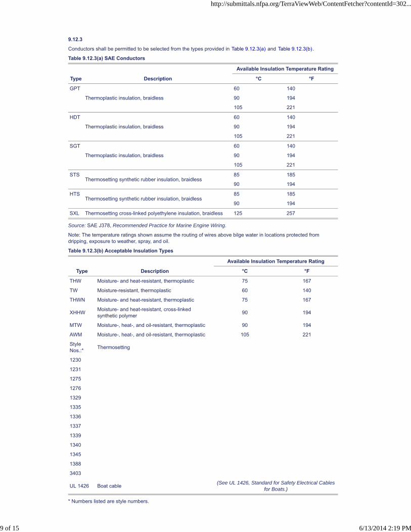
9.12.3
Conductors shall be permitted to be selected from the types provided in Table 9.12.3(a) and Table 9.12.3(b).
Table 9.12.3(a) SAE Conductors
Available Insulation Temperature Rating
Type Description °C °F
GPT
Thermoplastic insulation, braidless
60 140
90 194
105 221
HDT
Thermoplastic insulation, braidless
60 140
90 194
105 221
SGT
Thermoplastic insulation, braidless
60 140
90 194
105 221
STSThermosetting synthetic rubber insulation, braidless
85 185
90 194
HTSThermosetting synthetic rubber insulation, braidless
85 185
90 194
SXL Thermosetting cross-linked polyethylene insulation, braidless 125 257
Source: SAE J378, Recommended Practice for Marine Engine Wiring.
Note: The temperature ratings shown assume the routing of wires above bilge water in locations protected fromdripping, exposure to weather, spray, and oil.
Table 9.12.3(b) Acceptable Insulation Types
Available Insulation Temperature Rating
Type Description °C °F
THW Moisture- and heat-resistant, thermoplastic 75 167
TW Moisture-resistant, thermoplastic 60 140
THWN Moisture- and heat-resistant, thermoplastic 75 167
XHHWMoisture- and heat-resistant, cross-linkedsynthetic polymer
90 194
MTW Moisture-, heat-, and oil-resistant, thermoplastic 90 194
AWM Moisture-, heat-, and oil-resistant, thermoplastic 105 221
StyleNos.:*
Thermosetting
1230
1231
1275
1276
1329
1335
1336
1337
1339
1340
1345
1388
3403
UL 1426 Boat cable(See UL 1426, Standard for Safety Electrical Cables
for Boats.)
* Numbers listed are style numbers.
http://submittals.nfpa.org/TerraViewWeb/ContentFetcher?contentId=302...
9 of 15 6/13/2014 2:19 PM

9.12.4
Flexible cords shall conform with NFPA 70, National Electrical Code, and shall be selected from the types specified inTable 9.12.4.
Table 9.12.4 Flexible Cords
Type DescriptionInsulation Temperature
Rating Application
SOHard service cord—oil-resistantcompound
60°C (140°F)
75°C (167°F) and higherGeneral use except for machinery spaceGeneral use
ST Hard service cord— thermoplastic60°C (140°F)
75°C (167°F) and higherGeneral use except for machinery spaceGeneral use
STOHard service cord—oil-resistantthermoplastic
60°C (140°F)
75°C (167°F) and higherGeneral use except for machinery spaceGeneral use
SJOJunior hard service cord—oil-resistantcompound
60°C (140°F)
75°C (167°F) and higherGeneral use except for machinery spaceGeneral use
SJT Junior hard service cord—thermoplastic60°C (140°F)
75°C (167°F) and higher
General use except for machinery spaceGeneral use
SJTO Junior hard service cord—thermoplastic60°C (140°F)
75°C (167°F) and higher
General use except for machinery spaceGeneral use
http://submittals.nfpa.org/TerraViewWeb/ContentFetcher?contentId=302...
10 of 15 6/13/2014 2:19 PM

9.12.5
Conductors and flexible cords shall be stranded copper according to Table 9.12.5(a) and shall be sized in accordancewith Table 9.12.5(b).
Table 9.12.5(a) Conductor Circular Mil (CM) Area and Stranding
Conductor Size (AWG)
Minimum Acceptable
CM Areaa
Minimum Number of Strands
Type 2b Type 3c
18 1,537 16 —
16 2,336 19 26
14 3,702 19 41
12 5,833 19 65
10 9,343 19 105
8 14,810 19 168
6 25,910 37 266
4 37,360 49 420
2 62,450 127 665
1 77,790 127 836
1/0 98,980 127 1064
2/0 125,100 127 1323
3/0 158,600 259 1666
4/0 205,500 418 2107
Note: Metric wire sizes are to be used if of equivalent circular mil area. If the circular mil area of the metric conductor isless than that specified, the wire ampacity can be corrected based on the ratio of the circular mil area.
aApplies only to systems under 50 volts.
bConductors with Type 2 stranding, used for general-purpose wiring, which is subject to some movement from vibrationor minor flexing.
cConductors with Type 3 stranding, used for any wiring where flexing is involved in normal use.
Table 9.12.5(b) Allowable Amperage of Conductors for Under 50 Volts
Temperature Rating of Conductor Insulation
ConductorSize 60°C (140°F) 75°C (167°F) 80°C (176°F) 90°C (194°F) 105°C (221°F) 125°C (257°F)
200°C(392°F
English Metric
OutsideEngineSpaces
InsideEngineSpaces
OutsideEngineSpaces
InsideEngineSpaces
OutsideEngineSpaces
InsideEngineSpaces
OutsideEngineSpaces
InsideEngineSpaces
OutsideEngineSpaces
InsideEngineSpaces
OutsideEngineSpaces
InsideEngineSpaces
Outsidor
InsideEnginSpace
18 0.8 10 5.8 10 7.5 15 11.7 20 16.4 20 17.0 25 22.3 25
16 1 15 8.7 15 11.3 20 15.6 25 20.5 25 21.3 30 26.7 35
14 2 20 11.6 20 15.0 25 19.5 30 24.6 35 29.8 40 35.6 45
12 3 25 14.5 25 18.8 35 27.3 40 32.8 45 38.3 50 44.5 55
10 5 40 23.2 40 30.0 50 39.0 55 45.1 60 51.0 70 62.3 70
8 8 55 31.9 65 48.8 70 54.6 70 57.4 80 68.0 90 80.1 100
6 13 80 46.4 95 71.3 100 78.0 100 82.0 120 102.0 125 111.3 135
4 19 105 60.9 125 93.8 130 101.4 135 110.7 160 136.0 170 151.3 180
2 32 140 81.2 170 127.5 175 136.5 180 147.6 210 178.5 225 200.3 240
1 40 165 95.7 195 146.3 210 163.8 210 172.2 245 208.3 265 235.9 280
0 50 195 113.1 230 172.5 245 191.1 245 200.9 285 242.3 305 271.5 325
00 62 225 130.5 265 198.8 285 222.3 285 233.7 330 280.5 355 316.0 370
000 81 260 150.8 310 232.5 330 257.4 330 270.6 385 327.3 410 364.9 430
0000 130 300 174.0 360 270.0 385 330.3 385 315.7 445 378.3 475 422.8 510
http://submittals.nfpa.org/TerraViewWeb/ContentFetcher?contentId=302...
11 of 15 6/13/2014 2:19 PM

9.12.6
Conductors and flexible cords shall be sized for voltage drop as follows:
(1) 3 percent for panelboard main feeders
(2) 3 percent for navigation light circuits
(3) 3 percent for electronic equipment circuits
(4) 3 percent for bilge pump, blower, and refrigeration motor circuits
(5) 10 percent for all noncritical circuits not identified in 9.12.6(1) through 9.12.6(4)
9.12.7 Conductor Sizing Formula.
9.12.7.1
Conductor sizes shall be permitted to be calculated by means of the following formula.
where:
CM = circular mil area of conductor
K = 10.75 (constant representing the mil-foot resistance of copper)
I = load current in amperes
L = length of conductor from the positive power source connection to the electrical device and back to thenegative power source connection, measured in feet
E = voltage drop at load in volts (e.g., 12 volt @ 3 percent = 0.36)
9.12.7.2
If the circular mil area calculated in 9.12.7.1 is less than the value specified in Table 9.12.5(a), the next larger sizeconductor shall be used.
9.13 Wiring Installation.
9.13.1*
Current-carrying conductors shall be routed above the bilge water level and other areas where water can accumulatewhere the wiring and connectors are not watertight.
9.13.2*
Conductors, other than wiring on engines and exhaust temperature sensor wiring, shall be routed in a manner thatcomplies with the following criteria:
(1) There shall be a clearance of no less than 2 in. (5 cm) between conductors and water-cooled exhaustcomponents.
(2) There shall be a clearance of no less than 9 in. (23 cm) between conductors and dry exhaust components wherethe conductor is not directly above the exhaust.
(3) There shall be a clearance of no less than 18 in. (46 cm) between conductors and dry exhaust components whereconductors are located directly above the exhaust.
9.13.3 Battery Cables.
9.13.3.1
Battery cables shall not contact any metallic fuel system components.
9.13.3.2*
Where contact occurs between battery cables and nonmetallic fuel system components, cables shall be secured toprevent relative motion and abrasion between the two system components.
9.13.4 Physical Damage.
9.13.4.1
Conductors subject to exposure to physical damage shall be protected by loom, conduit, tape, raceways, or otherequivalent protection.
9.13.4.2
The protection required by 9.13.4.1 shall be self-draining.
9.13.4.3*
Conductors passing through or around bulkheads or structural members shall be protected to minimize insulationdamage such as chafing or compression. To minimize the potential for migration of carbon monoxide from machinerycompartments containing gasoline engines to adjacent accommodation compartments, bulkhead and deckpenetrations shall be in accordance with the requirements of 4.1.2.1.
http://submittals.nfpa.org/TerraViewWeb/ContentFetcher?contentId=302...
12 of 15 6/13/2014 2:19 PM
PIs [1] FR-25 Hide Legislative
9.13.4.4
Conductors shall be routed clear of sources of chafing such as steering cable and linkages, engine shafts and belts,and throttle connections.
9.13.5 Minimum Size.
9.13.5.1
Conductor sizes shall be no less than No. 16 gauge unless permitted otherwise by 9.13.5.2 or 9.13.5.3.
9.13.5.2
No. 18 gauge conductors shall be permitted to be used if they are included with other conductors in a sheath and donot extend more than 30 in. (75 cm) outside the sheath.
9.13.5.3
Conductor sizes shall be permitted to be less than No. 16 gauge where the conductor is contained completely withinequipment or enclosures.
9.13.6 Conductor Support.
9.13.6.1
Conductors shall be supported for their entire length unless permitted otherwise by 9.13.6.2 through 9.13.6.4.
9.13.6.2
Conductors shall be permitted to be supported at least every 18 in. (46 cm) by nonmetallic clamps of a size to hold theconductors firmly in place.
9.13.6.2.1
Nonmetallic straps or clamps shall not be used over engine(s), moving shafts, other machinery, or passageways iffailure can result in a hazardous condition.
9.13.6.2.2
Conductor material shall be resistant to oil, gasoline, and water and shall not break or crack under flexing within atemperature range of -30°F to 250°F (-34°C to 121°C).
9.13.6.3 Metal Straps Without Insulating Material.
9.13.6.3.1
Conductors, other than battery cables within 36 in. (91 cm) of a battery terminal and cables attached to outboardmotors, shall be permitted to be supported at least every 18 in. (46 cm) by metal straps or clamps with smooth,rounded edges.
9.13.6.3.2
Sections of the conductor or cable located directly under the strap or clamp shall be protected by means of loom, tape,or other suitable wrapping to prevent injury to the conductor.
9.13.6.4
Conductors shall be permitted to be supported at least every 18 in. (46 cm) by metal clamps lined with an insulatingmaterial resistant to the effects of oil, gasoline, and water.
9.13.7
Loom used to cover conductors shall be manufactured from material that is self-extinguishing, classified V-2 or better,in accordance with ANSI/UL 94, Tests for Flammability of Plastic Materials for Parts in Devices and Appliances .
9.14 Wiring Connections.
9.14.1 Metals.
9.14.1.1
Metals used for the terminal studs, nuts, and washers shall be corrosion resistant and galvanically compatible with theconductor and terminal lug.
9.14.1.2
Aluminum and unplated steel shall not be used for studs, nuts, and washers.
9.14.2
Wiring connections and terminals shall be designed specifically for use with stranded wire.
http://submittals.nfpa.org/TerraViewWeb/ContentFetcher?contentId=302...
13 of 15 6/13/2014 2:19 PM
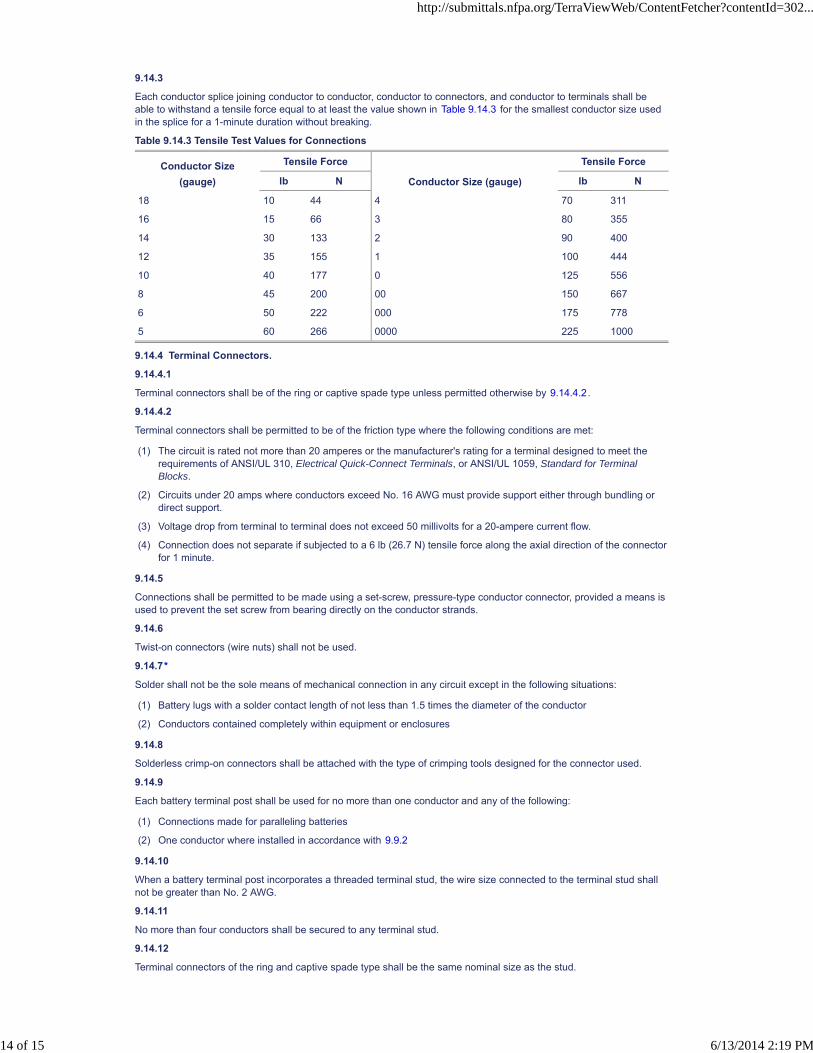
9.14.3
Each conductor splice joining conductor to conductor, conductor to connectors, and conductor to terminals shall beable to withstand a tensile force equal to at least the value shown in Table 9.14.3 for the smallest conductor size usedin the splice for a 1-minute duration without breaking.
Table 9.14.3 Tensile Test Values for Connections
Conductor Size(gauge)
Tensile Force
Conductor Size (gauge)
Tensile Force
lb N lb N
18 10 44 4 70 311
16 15 66 3 80 355
14 30 133 2 90 400
12 35 155 1 100 444
10 40 177 0 125 556
8 45 200 00 150 667
6 50 222 000 175 778
5 60 266 0000 225 1000
9.14.4 Terminal Connectors.
9.14.4.1
Terminal connectors shall be of the ring or captive spade type unless permitted otherwise by 9.14.4.2.
9.14.4.2
Terminal connectors shall be permitted to be of the friction type where the following conditions are met:
(1) The circuit is rated not more than 20 amperes or the manufacturer's rating for a terminal designed to meet therequirements of ANSI/UL 310, Electrical Quick-Connect Terminals, or ANSI/UL 1059, Standard for TerminalBlocks.
(2) Circuits under 20 amps where conductors exceed No. 16 AWG must provide support either through bundling ordirect support.
(3) Voltage drop from terminal to terminal does not exceed 50 millivolts for a 20-ampere current flow.
(4) Connection does not separate if subjected to a 6 lb (26.7 N) tensile force along the axial direction of the connectorfor 1 minute.
9.14.5
Connections shall be permitted to be made using a set-screw, pressure-type conductor connector, provided a means isused to prevent the set screw from bearing directly on the conductor strands.
9.14.6
Twist-on connectors (wire nuts) shall not be used.
9.14.7*
Solder shall not be the sole means of mechanical connection in any circuit except in the following situations:
(1) Battery lugs with a solder contact length of not less than 1.5 times the diameter of the conductor
(2) Conductors contained completely within equipment or enclosures
9.14.8
Solderless crimp-on connectors shall be attached with the type of crimping tools designed for the connector used.
9.14.9
Each battery terminal post shall be used for no more than one conductor and any of the following:
(1) Connections made for paralleling batteries
(2) One conductor where installed in accordance with 9.9.2
9.14.10
When a battery terminal post incorporates a threaded terminal stud, the wire size connected to the terminal stud shallnot be greater than No. 2 AWG.
9.14.11
No more than four conductors shall be secured to any terminal stud.
9.14.12
Terminal connectors of the ring and captive spade type shall be the same nominal size as the stud.
http://submittals.nfpa.org/TerraViewWeb/ContentFetcher?contentId=302...
14 of 15 6/13/2014 2:19 PM
9.14.13
Conductors terminating at switchboards in junction boxes or at fixtures shall be arranged to provide a length ofconductor to relieve tension, to allow for repairs, and to permit multiple conductors to be fanned at terminal studs.
9.14.14
The shanks of terminals, other than those used in grounding systems, shall be protected against accidental shorting bythe use of insulation barriers or sleeves.
9.15 Receptacles.
9.15.1
Receptacles shall be installed in locations normally not subject to rain, spray, or flooding, or shall be protected asfollows:
(1) Weatherproof if subject to rain or spray
(2) Watertight if subject to flooding
9.15.2
Receptacles and matching plugs used on dc systems shall not be interchangeable with receptacles and matching plugsused elsewhere on the boat for ac systems.
9.16 Plug Connectors.
Connectors used in conjunction with harness-type wiring systems shall comply with the following:
(1) Connectors shall incorporate means such as cable clamps, molded connectors, insulation grips, or extendedterminal barrels to limit flexing at the connection.
(2) Connectors exposed to weather shall be weatherproof.
(3) Connectors subject to immersion shall be watertight.
(4) Each terminal in a multiwire connector shall be protected from accidental short-circuiting to adjacent terminals.
(5) Connectors shall have provisions such that they will not disengage when a force of 6 lb (26.7 N) is applied alongthe axial direction of the connector for 1 minute.
http://submittals.nfpa.org/TerraViewWeb/ContentFetcher?contentId=302...
15 of 15 6/13/2014 2:19 PM

NFPA 302®, Fire Protection Standard for Pleasure and Commercial Motor Craft, 2010 Edition
NFPA STANDARDS DEVELOPMENT SITEFIRST DRAFT REPORTClosing Date: February 22, 2013 NOTE: All Public Comment must be received by 5:00 pm EST/EDST on the published Closing Date.
Quick Print
PIs [1]
Chapter 10* Alternating Current (ac) Electrical Systems on Boats
10.1* Scope.
The standards and practices of this chapter establish requirements for the design and installation of ac electrical systems on boatsoperating at frequencies of 50 or 60 hertz and less than 300 volts, including shore-powered systems up to the point of connection tothe shore outlet.
10.2 General Requirements.
10.2.1 Conductor Length Measurement.
All lengths for conductors shall be measured along the conductors.
10.2.2
The system shall be polarized.
10.2.3 Grounded Neutral System.
10.2.3.1
A grounded neutral system shall be required unless otherwise permitted by 10.2.4.
10.2.3.2*
The neutral shall be grounded only at the power source.
10.2.3.3
A shore power neutral grounded through the shore power cable shall not be grounded on the boat.
10.2.4 Transformer Grounding.
10.2.4.1
On systems using an isolation or polarization transformer, the generator or inverter neutral shall be permitted to be the transformer.
10.2.4.2
Secondary neutrals shall be permitted to be grounded at a main grounding bus instead of at the generator inverter or transformersecondaries.
10.2.5
The boat's ac system grounding (green, or green with yellow stripe) conductor shall be connected to the engine negative terminal orits bus.
10.2.6
Individual circuits shall not be capable of being energized by more than one source of electrical power at a time, and each shorepower inlet or generator shall be a separate source of electrical power.
10.2.7 Energized Parts.
10.2.7.1
Energized parts of electrical equipment shall be protected against accidental contact by the use of enclosures or other protectivemeans.
10.2.7.2
The protective means required in 10.2.7.1 shall not be used for nonelectrical equipment and electrical equipment together.
10.2.7.3
Access to enclosures containing energized parts of electrical equipment shall require the use of hand tools.
10.2.8
The transfer from one power source circuit to another shall be made by a means that opens all current-carrying conductors,including neutrals, before closing the alternate source circuit, and that prevents arc over between sources.
10.3 Marking.
10.3.1 Shore Power Inlet Warning.
http://submittals.nfpa.org/TerraViewWeb/ContentFetcher?contentId=302...
1 of 17 6/13/2014 2:19 PM

10.3.1.1
A permanently mounted, waterproof warning label shall be located alongside each shore power inlet location on the boat and shallcontain at a minimum the following informational elements, unless permitted otherwise by 10.3.1.2 or 10.3.1.3:
WARNING:Electrical shock and fire hazard. Failure to follow these instructions can result in injury or death.(1) Turn off the boat's shore connection switch before connecting or disconnecting shore cable.(2) Connect shore power cable at the boat first. (3) Immediately disconnect cable if polarity warning indicator is activated.(4) Disconnect shore power cable at shore outlet first.(5) Close shore power inlet cover tightly.(6) Do not alter shore power cable connectors.
10.3.1.2
If a polarity indicator is not required, the informational element (3) shall not be required for the label specified in 10.3.1.1.
10.3.1.3
If the shore power cable is permanently connected to the boat, the informational elements (2) and (5) shall not be required for thelabel specified in 10.3.1.1.
10.3.2 Marking of Controls.
10.3.2.1
Switches and electrical controls shall be marked to indicate their use unless otherwise permitted by 10.3.2.2.
10.3.2.2
A switch or electrical control shall not be required to be marked where it meets the following criteria:
(1) Its purpose is obvious.
(2) Its erroneous operation cannot cause a hazardous condition.
10.3.3 Marking of Equipment.
Electrical equipment, unless it is part of an identified assembly, shall be marked or identified by the manufacturer to indicate thefollowing:
(1) Manufacturer's identification
(2) Model number
(3) Rating in volts and amperes or volts and watts
(4) Phase identification, if applicable
(5) Ignition protection, if applicable
10.4 System Voltage.
Nominal system voltages for ac electrical systems shall be one of the following:
(1) 120 volts ac, single-phase
(2) 240 volts ac, single-phase
(3) 120/240 volts ac, single-phase
(4) 120/240 volts ac, delta three-phase
(5) 120/208 volts ac, wye three-phase
10.5 Ambient Temperature.
The ambient temperature of machinery spaces shall be considered to be 122°F (50°C), and the ambient temperature of all otherspaces shall be considered to be 86°F (30°C).
10.6 Ignition Source.
10.6.1
Potential sources of ignition, except those isolated from a gasoline fuel source in accordance with 10.6.2, shall be ignition protectedif located in spaces containing one of the following:
(1) Gasoline-powered machine
(2) Gasoline fuel tank
(3) Joint, fitting, or other connection between components of a gasoline fuel system
http://submittals.nfpa.org/TerraViewWeb/ContentFetcher?contentId=302...
2 of 17 6/13/2014 2:19 PM

10.6.2*
An electrical component shall be considered to be isolated from a gasoline fuel source provided that one of the following conditionsis met:
(1) The distance between the electrical component and the gasoline fuel source is at least 2 ft (0.6 m), and the space is open tothe atmosphere.
(2) Electrical component is located below the gasoline fuel source, and a means is provided to prevent gasoline fuel and vaporsthat can leak from the gasoline fuel sources from exposure to the electrical component.
(3) Electrical component is located above the gasoline fuel source, and a deck or other enclosure is located between the ignitionsource and the gasoline fuel source.
(4)
10.7 Shore Power Polarity Devices.
10.7.1*
Reverse-polarity indicating devices having a continuously visible or audible signal shall be installed in 120-volt ac shore powersystems, where there is no polarization or isolation transformer that establishes the polarity of the onboard system, and one of thefollowing conditions exists:
(1) The polarity of the system must be maintained for the proper operation of electrical devices in the system.
(2) A branch circuit is provided with overcurrent protection in the ungrounded current-carrying conductors only.
10.7.2
The total impedance of polarity-indicating and protection devices connected between normal current-carrying conductors and thegrounding conductor shall be not less than 25,000 ohms at 120 volts, 60 hertz at all times.
* A bulkhead is located between the gasoline fuel source and ignition source that meets the following criteria:
(a) Separates the electrical component(s) from the gasoline fuel source and extends the length of both the vertical andhorizontal distances of the open space between the gasoline fuel source and the ignition source
(b) Resists a water level of 12 in. (30 cm) or of one-third the maximum height of the bulkhead, whichever is lower, withoutseepage of more than 1⁄4 fl oz (7.4 ml) of fresh water per hour
(c) Has no opening higher than 12 in. (30 cm) or one-third the maximum height of the bulkhead, whichever is lower, unlessthe opening meets the following criteria:
i. Is used for the passage of items such as conductors, piping, ventilation ducts, and mechanical equipment, or fordoors, hatches, and access panels
ii. Has a maximum annular space around each item passing through it not more than 1⁄4 in. (6.4 mm)
http://submittals.nfpa.org/TerraViewWeb/ContentFetcher?contentId=302...
3 of 17 6/13/2014 2:19 PM

10.7.3
http://submittals.nfpa.org/TerraViewWeb/ContentFetcher?contentId=302...
4 of 17 6/13/2014 2:19 PM
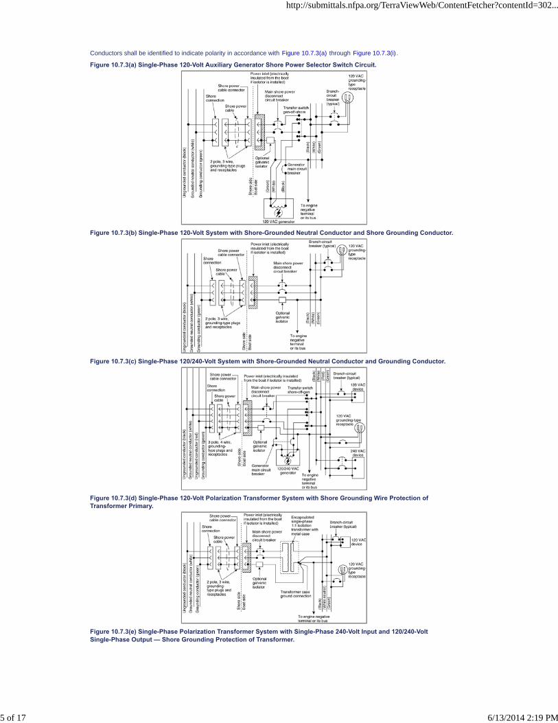
Conductors shall be identified to indicate polarity in accordance with Figure 10.7.3(a) through Figure 10.7.3(i) .
Figure 10.7.3(a) Single-Phase 120-Volt Auxiliary Generator Shore Power Selector Switch Circuit.
Figure 10.7.3(b) Single-Phase 120-Volt System with Shore-Grounded Neutral Conductor and Shore Grounding Conductor.
Figure 10.7.3(c) Single-Phase 120/240-Volt System with Shore-Grounded Neutral Conductor and Grounding Conductor.
Figure 10.7.3(d) Single-Phase 120-Volt Polarization Transformer System with Shore Grounding Wire Protection ofTransformer Primary.
Figure 10.7.3(e) Single-Phase Polarization Transformer System with Single-Phase 240-Volt Input and 120/240-VoltSingle-Phase Output — Shore Grounding Protection of Transformer.
http://submittals.nfpa.org/TerraViewWeb/ContentFetcher?contentId=302...
5 of 17 6/13/2014 2:19 PM

Figure 10.7.3(f) Single-Phase 120-Volt Isolation Transformer System with Boat-Grounded Secondary, Shore-GroundedTransformer Shield, and Boat-Grounded Transformer Metal Case.
Figure 10.7.3(g) Isolation Transformer System — Single-Phase 240-Volt Input and 120/240-Volt Output with Boat-GroundedSecondary, Shore-Grounded Transformer Shield, and Boat-Grounded Transformer Metal Case.
Figure 10.7.3(h) Single-Phase 120-Volt System with Polarity Indicating Device, Shore-Grounded Neutral Conductor, andShore-Grounded Grounding Conductor.
Figure 10.7.3(i) Polarization Transformer System — Single-Phase 240-Volt Input and 120/240-Volt Output — Generator withMain ac Grounding Bus.
http://submittals.nfpa.org/TerraViewWeb/ContentFetcher?contentId=302...
6 of 17 6/13/2014 2:19 PM
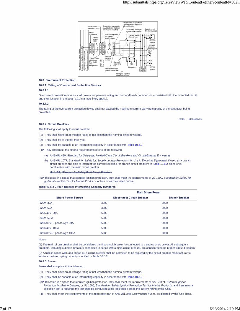
FR-55 Hide Legislative
10.8 Overcurrent Protection.
10.8.1 Rating of Overcurrent Protection Devices.
10.8.1.1
Overcurrent protection devices shall have a temperature rating and demand load characteristics consistent with the protected circuitand their location in the boat (e.g., in a machinery space).
10.8.1.2
The rating of the overcurrent protection device shall not exceed the maximum current-carrying capacity of the conductor beingprotected.
10.8.2 Circuit Breakers.
The following shall apply to circuit breakers:
(1) They shall have an ac voltage rating of not less than the nominal system voltage.
(2) They shall be of the trip-free type.
(3) They shall be capable of an interrupting capacity in accordance with Table 10.8.2.
(4)
(5)
Table 10.8.2 Circuit-Breaker Interrupting Capacity (Amperes)
Main Shore Power
Shore Power Source Disconnect Circuit Breaker Branch Breaker
120V–30A 3000 3000
120V–50A 3000 3000
120/240V–50A 5000 3000
240V–50 A 5000 3000
120/208V–3-phase/wye 30A 5000 3000
120/240V–100A 5000 3000
120/208V–3-phase/wye 100A 5000 3000
Notes:
(1) The main circuit breaker shall be considered the first circuit breaker(s) connected to a source of ac power. All subsequentbreakers, including submain breakers connected in series with a main circuit breaker, are considered to be branch circuit breakers.
(2) A fuse in series with, and ahead of, a circuit breaker shall be permitted to be required by the circuit-breaker manufacturer toachieve the interrupting capacity specified in Table 10.8.2.
10.8.3 Fuses.
Fuses shall comply with the following:
(1) They shall have an ac voltage rating of not less than the nominal system voltage.
(2) They shall be capable of an interrupting capacity in accordance with Table 10.8.2.
(3)
(4) They shall meet the requirements of the applicable part of ANSI/UL 248, Low Voltage Fuses, as dictated by the fuse class.
* They shall meet the marine requirements of one of the following:
(a) ANSI/UL 489, Standard for Safety for Molded-Case Circuit Breakers and Circuit-Breaker Enclosures
(b) ANSI/UL 1077, Standard for Safety for Supplementary Protectors for Use in Electrical Equipment, if used as a branchcircuit breaker and able to interrupt the current specified for branch circuit breakers in Table 10.8.2 alone or incombination with the main circuit breaker
UL 1133, Standard for Safety Boat Circuit Breakers
* If located in a space that requires ignition protection, they shall meet the requirements of UL 1500, Standard for Safety forIgnition-Protection Test for Marine Products, at four times their rated current.
* If located in a space that requires ignition protection, they shall meet the requirements of SAE J1171, External IgnitionProtection for Marine Devices, or UL 1500, Standard for Safety Ignition-Protection Test for Marine Products; and if an internalexplosion test is required, the test shall be conducted at no less than 4 times the current rating of the fuse.
http://submittals.nfpa.org/TerraViewWeb/ContentFetcher?contentId=302...
7 of 17 6/13/2014 2:19 PM

10.8.4 Fuse Holders.
Fuse holders shall meet the requirements of ANSI/UL 512, Standard for Safety Fuseholders, for the class of fuse being used.
10.9 Main Supply.
10.9.1
Common-trip circuit breakers shall be provided in main supply conductors as follows:
(1) 120-volt ac, single-phase — ungrounded and grounded conductors (white)
(2) 240-volt ac, single-phase — both ungrounded conductors
(3) 120/240-volt ac, single-phase — both ungrounded conductors
(4) 120/240-volt ac, delta three-phase — all ungrounded conductors
(5) 120/208-volt ac, wye three-phase — all ungrounded conductors
10.9.2 Supply Feeders Exceeding 10 ft (3 m).
10.9.2.1*
If the location of the main feeder supply disconnect circuit breaker is in excess of 10 ft (3 m) from the shore power inlet or theelectrical attachment point of a permanently installed shore power cord, additional fuses or circuit breakers shall be provided within10 ft (3 m) of the inlet or attachment point to the electrical system of the boat.
10.9.2.2
If additional fuses are required by 10.9.2.1, their rating shall be such that circuit breakers trip before the fuses open the circuit in theevent of overload.
10.9.2.3
If additional fuses are required by 10.9.2.1, the ampere rating of the additional fuses or circuit breaker shall not exceed 125 percentof the rating of the main shore power disconnect circuit breaker.
10.9.3* Overcurrent Protection Location.
Conductors shall be provided with overcurrent protection at the source of power unless permitted by 10.9.3.1, 10.9.3.2, or10.9.3.3.
10.9.3.1
Where not practical to locate overcurrent protection at the source of power, conductors shall be provided with overcurrent protectionno more than 7 in. (18 cm) from the point at which the conductor is connected to the source of power measured along theconductor.
10.9.3.2
If the conductor is contained in a sheath or enclosure, such as a junction box, control box, or enclosed panel, throughout therequired distance, and where not practical to locate overcurrent protection at the source of power, conductors shall be provided withovercurrent protection no more than 40 in. (102 cm) from the point at which the conductor is connected to the source of power.
10.9.3.3
If the conductor is connected directly to the battery terminal, and where not practical to locate overcurrent protection at the source ofpower, conductors shall be provided with overcurrent protection no more than 72 in. (183 cm) from the battery terminal.
10.9.4
Self-limiting generators, whose maximum overload current does not exceed 120 percent of its rated current output, shall not berequired to have external overcurrent protection.
10.10 Branch Circuits.
10.10.1 Ungrounded Conductor.
10.10.1.1
Each ungrounded conductor of a branch circuit shall be provided with overcurrent protection at the point of connection to thepanelboard bus.
10.10.1.2
Each circuit breaker or fuse required by 10.10.1.1 shall not be rated in excess of the current rating of the smallest conductorbetween the fuse or circuit breaker and the load.
10.10.2
In branch circuits, circuit breakers and switches shall open all grounded and ungrounded conductors simultaneously except for thefollowing conductors:
(1) A polarized circuit with a polarity indicator
(2) The neutral leg of a grounded secondary of a polarization or isolation transformer
10.10.3
Fuses shall not be used in the grounded conductor.
10.10.4
If circuits contain two or more ungrounded current-carrying conductors that are protected by fuses, means shall be provided todisconnect all energized legs of the circuit simultaneously or to remove all fuses from the circuit simultaneously.
10.10.5
All ac branch-circuit conductors to receptacles or equipment, other than those contained completely within equipment or enclosures,shall be of the jacketed type.
http://submittals.nfpa.org/TerraViewWeb/ContentFetcher?contentId=302...
8 of 17 6/13/2014 2:19 PM
10.10.6 Alternating Current (ac) Motors.
10.10.6.1
Each motor or motor-operated device shall be individually protected by an overcurrent protection device unless the motor will notoverheat under locked rotor conditions.
10.10.6.2
The overcurrent protection device shall not be rated at more than 125 percent of the motor full-load current rating.
10.10.6.3
The overcurrent protection device shall be permitted to be integral and of an automatic resetting type.
10.10.7 Battery Chargers and Inverters.
10.10.7.1
Each ungrounded conductor to a battery charger shall be provided with overcurrent protection at the point of connection to the mainswitchboard or the distribution panel.
10.10.7.2
Battery chargers, inverters, and inverter/chargers, and their installation shall comply with the requirements of ABYC A-31, BatteryChargers and Inverters.
10.10.7.3
Each battery charger shall be fitted with a means of indicating the output current.
10.11 Ground-Fault Circuit Interrupters (GFCIs).
10.11.1
A GFCI shall be permitted to be used on any single-phase ac circuit and shall be used for all receptacles in a head, a galley, or amachinery space or on a weather deck as required by 10.15.7.
10.11.2
GFCI breakers shall comply with the following:
(1) They shall meet the requirements of ANSI/UL 943, Standard for Safety Ground-Fault Circuit-Interrupters, and ANSI/UL 489,Standard for Safety Molded-Case Circuit Breakers and Circuit-Breaker Enclosures.
(2) They shall be permitted to be installed as panelboard feeder breakers to protect all associated circuits, or in individual branchcircuits.
10.11.3
GFCI receptacle devices shall comply with the following:
(1) They shall meet the requirements of ANSI/UL 943, Standard for Safety Ground-Fault Circuit-Interrupters, and ANSI/UL 498,Standard for Safety Attachment Plugs and Receptacles.
(2) They shall be permitted to be installed as part of a convenience outlet installation, either in single outlet applications or inmultiple “feed-through” installations.
10.11.4*
GFP circuit breakers shall be permitted to be installed as the main breaker on the primary side of isolation transformers.
10.12 Appliances and Equipment.
10.12.1
Appliances and fixed ac electrical equipment used on boats shall be designed so that the current-carrying parts of the device areinsulated effectively from all exposed electrically conductive parts.
10.12.2
All exposed electrically conductive non-current-carrying parts of fixed ac electrical equipment and appliances intended to begrounded shall be connected to the grounding system.
10.12.3
If an appliance has a neutral-to-ground bonding strap, the bonding strap shall be removed.
10.13 Conductors and Flexible Cords.
10.13.1
Conductors shall have a minimum rating of 600 volts.
10.13.2
Flexible cords shall have a minimum rating of 300 volts.
10.13.3
Conductors shall be selected from the types specified in Table 9.12.3(b) .
10.13.4
Flexible cords shall be selected from the types specified in Table 9.12.4.
http://submittals.nfpa.org/TerraViewWeb/ContentFetcher?contentId=302...
9 of 17 6/13/2014 2:19 PM
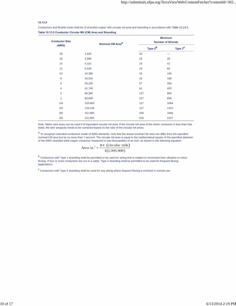
10.13.5
Conductors and flexible cords shall be of stranded copper with circular mil area and stranding in accordance with Table 10.13.5.
Table 10.13.5 Conductor Circular Mil (CM) Area and Stranding
Conductor Size(AWG) Nominal CM Areaa
MinimumNumber of Strands
Type 2b Type 3c
18 1,620 16 —
16 2,580 19 26
14 4,110 19 41
12 6,530 19 65
10 10,380 19 105
8 16,510 19 168
6 26,240 37 266
4 41,740 61 420
2 66,360 127 665
1 83,690 127 836
1/0 105,600 127 1064
2/0 133,100 127 1323
3/0 167,800 259 1666
4/0 211,600 418 2107
Note: Metric wire sizes can be used if of equivalent circular mil area. If the circular mil area of the metric conductor is less than thatlisted, the wire ampacity needs to be corrected based on the ratio of the circular mil areas.
a To recognize stranded conductors made of AWG elements, note that the actual nominal CM area can differ from the specifiednominal CM area but by no more than 7 percent. The circular mil area is equal to the mathematical square of the specified diameterof the AWG stranded solid copper conductor measured in one-thousandths of an inch, as shown in the following equation:
b Conductors with Type 2 stranding shall be permitted to be used for wiring that is subject to movement from vibration or minorflexing. If four or more conductors are run in a cable, Type 2 stranding shall be permitted to be used for frequent flexingapplications.
c Conductors with Type 3 stranding shall be used for any wiring where frequent flexing is involved in normal use.
http://submittals.nfpa.org/TerraViewWeb/ContentFetcher?contentId=302...
10 of 17 6/13/2014 2:19 PM

FR-51 Hide Legislative
10.13.6
Conductor sizes, as determined by Table 10.13.5, shall not carry current greater than that indicated in Table 10.13.6(a) , based onthe temperature rating of the wire, and the following derating factors:
(1) Conductors used in or routed through an engine space shall be corrected in accordance with Table 10.13.6(b).
(2) Current-carrying conductors that are bundled shall be derated in accordance with Table 10.13.6(c).
Table 10.13.6(a) Ampacities of Insulated Conductors
Temperature Rating of Conductor Insulation
Conductor Size (AWG)60°C
(140°F)75°C
(167°F)80°C
(176°F)90°C
(194°F)105°C
(221°F)125°C
(257°F)200°C
(392°F)
18 10 10 15 20 20 25 25
16 15 15 20 25 25 30 35
14 20 20 25 30 35 40 45
12 25 25 35 40 45 50 55
10 40 40 50 55 60 70 70
8 55 65 70 70 80 90 100
6 80 95 100 100 120 125 135
4 105 125 130 135 160 170 180
3 120 145 150 155 180 195 210
2 140 170 175 180 210 225 240
1 165 195 210 210 245 265 280
0 195 230 245 245 285 305 325
00 225 265 285 285 330 355 370
000 260 310 330 330 385 410 430
0000 300 360 385 385 445 475 510
Table 10.13.6(b) Engine Room Temperature Derating Factor
60°C(140°F)
75°C(167°F)
80°C(176°F)
90°C(194°F)
105°C(221°F)
125°C(257°F)
220°C(392°F)
Temperature rating of conductor 0.58 0.75 0.78 0.82 0.85 0.89 1.00
Table 10.13.6(c) Current-Carrying Conductor Bundling Derating Factor
Number of Energized Wires in a Bundle Correction Factor
3 0.70
4 to 6 0.60
7 to 24 0.50
25 and above 0.40
10.13.7
Conductors, other than those contained completely within equipment or enclosures, shall be at least No. 16 AWG.
10.13.8
All conductors shall meet UL 1426, Standard for Safety Electrical Cables for Boats, and shall be so labeled.
10.14 Installation.
10.14.1
All connections normally carrying current shall be made in enclosures with interior surfaces having a flame spread rating of notmore than 25 as tested in accordance with NFPA 255 , Standard Method of Test of Surface Burning Characteristics of BuildingMaterials ASTM E84, Standard Test Method for Surface Burning Characteristics of Building Materials .
10.14.2
All conductors, other than those contained completely within equipment or enclosures, shall be supported to relieve strain onconnections.
10.14.3
Where ac and dc conductors are run together, other than conductors contained completely within equipment or enclosures, the acconductors shall be sheathed, bundled, or otherwise kept separate from the dc conductors.
10.14.4* Conductor Support.
10.14.4.1
Conductors shall be supported for their entire length unless permitted otherwise by 10.14.4.2 through 10.14.4.4.
10.14.4.2
http://submittals.nfpa.org/TerraViewWeb/ContentFetcher?contentId=302...
11 of 17 6/13/2014 2:19 PM
Conductors shall be permitted to be supported at least every 18 in. (46 cm) by nonmetallic clamps of a size to hold the conductorsfirmly in place.
10.14.4.2.1
Nonmetallic straps or clamps shall not be used over engine(s), moving shafts, other machinery, or passageways if failure can resultin a hazardous condition.
10.14.4.2.2
Conductor material shall be resistant to oil, gasoline, and water and shall not break or crack under flexing within a temperaturerange of -30°F to 250°F (-34°C to 121°C).
10.14.4.3 Metal Straps with Insulating Material.
10.14.4.3.1
Conductors shall be permitted to be supported at least every 18 in. (46 cm) by metal straps or clamps with smooth, rounded edgesto hold the conductors firmly in place without damage to the conductors or insulation.
10.14.4.3.2
Sections of the conductor or cable located directly under the strap or clamp shall be protected by means of loom, tape, or othersuitable wrapping to prevent injury to the conductor.
10.14.4.4
Conductors shall be permitted to be supported at least every 18 in. (46 cm) by metal clamps lined with an insulating materialresistant to the effects of oil, gasoline, and water.
10.14.5
Junction boxes, cabinets, and other enclosures in which electrical connections are made shall be weatherproof or installed in aprotected location to minimize the entrance or accumulation of moisture or water within the boxes, cabinets, or enclosures.
10.14.6
In wet locations, metallic boxes, cabinets, or enclosures shall be mounted to minimize the entrapment of moisture between the box,cabinet, or enclosure and the adjacent structure.
10.14.7
If an air space is used to achieve the requirement of 10.14.6, the space shall be no less than 1⁄4 in. (6.4 mm).
10.14.8
Unused openings in boxes, cabinets, and weatherproof enclosures shall be closed.
10.14.9*
Current-carrying conductors shall be routed above the bilge water level and other areas where water can accumulate unless thewiring is of a submersible type, and connections shall be watertight.
10.14.10*
Conductors shall be routed in accordance with the following criteria:
(1) Unless an equivalent thermal barrier is provided, there shall be a clearance of no less than 2 in. (5 cm) between conductorsand water-cooled exhaust components.
(2) There shall be a clearance of no less than 9 in. (23 cm) between conductors and dry exhaust components where theconductor is not directly above the exhaust.
(3) Conductors shall not be routed directly above a dry exhaust.
10.14.11 Physical Damage.
10.14.11.1
Conductors subject to physical damage shall be protected by loom, conduit, tape, raceways, or other equivalent protection.
10.14.11.2
The protection required by 10.14.11.1 shall be self-draining.
10.14.11.3
Conductors passing through or around bulkheads or structural members shall be protected to minimize insulation damage such aschafing or compression.
10.14.11.4
Conductors also shall be routed clear of sources of chafing such as steering cable and linkages, engine shafts, and throttleconnections.
10.14.12
All permanently installed appliances and utilization equipment shall be mounted securely to the boat's structure.
10.14.13 Wiring Connections.
10.14.13.1
Wiring connections shall be designed and installed to make mechanical and electrical joints without damage to the conductors.
10.14.13.2 Metals.
10.14.13.2.1
Metals used for the terminal studs, nuts, and washers shall be corrosion resistant and galvanically compatible with the conductorand terminal lug.
http://submittals.nfpa.org/TerraViewWeb/ContentFetcher?contentId=302...
12 of 17 6/13/2014 2:19 PM
10.14.13.2.2
Aluminum and unplated steel shall not be used for studs, nuts, and washers.
10.14.13.2.3
Each conductor splice joining conductor to conductor, conductor to connectors, and conductor to terminals shall be able towithstand a tensile force equal to at least the value shown in Table 9.14.3 for the smallest conductor size used in the splice for a1-minute duration without breaking.
10.14.13.3 Terminal Connectors.
10.14.13.3.1
Terminal connectors shall be of the ring or captive spade type unless permitted otherwise by 10.14.13.3.2.
10.14.13.3.2
Terminal connectors shall be permitted to be of the friction type where the following conditions are met:
(1) Circuit is rated at not more than 20 amperes or the manufacturer's rating if the terminal design meets the requirements ofANSI/UL 310, Standard for Electrical Quick-Connect Terminals, or ANSI/UL 1059, Standard for Terminal Blocks.
(2) Voltage drop from terminal to terminal does not exceed 50 millivolts for a 20-ampere current flow.
(3) Connection does not separate if subjected to a 6 lb (26.7 N) tensile force along the axial direction of the connector for 1minute.
10.14.14 Set-Screw, Pressure-Type Connectors.
10.14.14.1
Connections shall be permitted to be made using a set-screw, pressure-type conductor connector.
10.14.14.2
The connectors addressed in 10.14.14.1 shall be provided with a means to prevent the set screw from bearing directly on theconductor strands.
10.14.15
Twist-on connectors (wire nuts) shall not be used.
10.14.16
Solder shall not be the sole means of mechanical connection in any circuit unless the conductor is contained completely withinequipment or enclosures.
10.14.17
Solderless crimp-on connectors shall be attached with the type of crimping tools designed for the connector used.
10.14.18
No more than four conductors shall be secured to any terminal stud.
10.14.19
Two or more terminal studs shall be connected together by means of jumpers or copper straps where more than four conductorswould be needed at a terminal stud.
10.14.20
Terminal connectors of the ring and captive spade type shall be the same nominal size as the stud.
10.14.21
Conductors terminating at panelboards in junction boxes or fixtures shall be arranged to provide a length of conductor to relievetension, to allow for repairs, and to permit multiple conductors to be fanned at terminal studs.
10.14.22
The shanks of terminals, other than those used in grounding systems, shall be protected against accidental shorting by the use ofinsulation barriers or sleeves.
10.15 Receptacles.
10.15.1
Receptacles shall be installed in locations normally not subject to rain, spray, or flooding, or shall be protected as follows:
(1) Weatherproof if subject to rain or spray
(2) Watertight if subject to flooding
10.15.2
Receptacles shall be of the grounding type with a terminal provided for the grounding (green, or green with yellow stripe) conductorin accordance with ANSI/NEMA WD-6, Wiring Devices — Dimensional Requirements.
10.15.3
Receptacles and matching plugs used on ac systems shall not be interchangeable with receptacles and matching plugs used on dcsystems.
http://submittals.nfpa.org/TerraViewWeb/ContentFetcher?contentId=302...
13 of 17 6/13/2014 2:19 PM

10.15.4
Power wiring for receptacles shall be connected as follows:
(1) They shall be connected so that the grounded (white) conductor attaches to the terminal identified by a letter(s) or a light color(normally silver).
(2) They shall be connected so that the ungrounded conductor(s) shall be attached to the terminal identified by a letter(s) or a darkcolor (normally brass or copper).
10.15.5
A branch circuit supplying a combination of receptacle loads and permanently connected loads shall not supply fixed loads inexcess of the following:
(1) 600 W for a 15-ampere circuit
(2) 1000 W for a 20-ampere circuit
10.15.6
Receptacles provided for the galley shall be located so that, when appliance cords are plugged in, they do not cross a traffic area,galley stove, or sink.
10.15.7*
If installed in a head, a galley, or a machinery space or on a weather deck, the receptacle shall be protected by a Type A (nominal 5milliamperes) GFCI.
10.15.8
Electrical systems not equipped with polarity indicators using two-pole circuit breakers shall use a two-pole GFCI breaker in place ofsingle-pole GFCI receptacles in the circuits that supply receptacles, unless the system employs polarization or isolationtransformers that establish the polarity on the boat.
10.16 Main Panelboard.
10.16.1
A main panelboard shall meet the following criteria:
(1) It shall be installed in a readily accessible location.
(2) It shall be weatherproof or protected from weather and splash.
10.16.2
A main panelboard shall be permitted to serve as a distribution center.
10.16.3
Boats equipped with both ac and dc electrical systems shall have their distribution on separate panelboards or, in the case ofsystems with combined ac and dc panelboards, the panel shall be designed so that when the panel is open there is no access toenergized ac parts without the use of tools.
10.16.4
Panelboards shall be permanently marked with the system voltage value and either “VAC” or the system frequency (e.g., “120 VAC”or “120V-60 hertz”).
10.16.5
If the frequency is other than 60 hertz, the frequency shall be indicated.
10.16.6
For three-phase systems the following shall be indicated:
(1) System voltage
(2) Phase
(3) Number of conductors
10.16.7 Voltmeters.
10.16.7.1
A system voltmeter shall be installed for any of the following situations:
(1) System is designed to supply motor circuits.
(2) Onboard generator is installed.
(3) Inverter.
10.16.7.2
Where a voltmeter is required by 10.16.7.1(3), the voltmeter shall be located on or in close proximity to the panelboard.
10.17 Alternating-Current (ac) Generators.
10.17.1
Alternating-current generators shall be connected to the electrical distribution system through a selector switch in accordance with10.2.8 and Figure 10.7.3(a) through Figure 10.7.3(i) .
10.17.2 Power Feeders.
10.17.2.1
Power feeders from ac generators shall be sized to accommodate at least the generator's maximum rated output.
http://submittals.nfpa.org/TerraViewWeb/ContentFetcher?contentId=302...
14 of 17 6/13/2014 2:19 PM

PIs [1]
FR-27 Hide Legislative
10.17.2.2
The power feeder shall be protected at the generator with overcurrent protection devices in accordance with Section 10.8 unlessthe generator is a self-limiting generator having a maximum overload current of no more than 120 percent of the generator's ratedcurrent output.
10.17.2.3
The rating of overcurrent protection devices required by 10.17.2.2 shall not exceed 120 percent of the generator's rated output.
10.18 Isolation of Galvanic Currents.
10.18.1
Boats using an isolation transformer to reduce galvanic corrosion shall use an isolation transformer system in accordance withABYC E-11, AC and DC Electrical Systems on Boats, and 10.20.4 or 10.20.7.
10.18.2
Boats using a galvanic isolator to reduce galvanic corrosion shall use a galvanic isolator in the grounding conductor in accordancewith ABYC A-28, Galvanic Isolators.
10.19 Shore Power.
10.19.1 Power Inlet.
10.19.1.1
The receptacle installed to receive a connecting cable to carry ac shore power aboard shall be a male-type connector.
10.19.1.2
Power inlets shall comply with the following:
(1) Power inlets installed in locations subject to rain, spray, or splash shall be weatherproof, whether or not in use.
(2) Power inlets installed in areas subject to flooding or momentary submersion shall be watertight, whether or not in use.
(3) A warning label shall be located alongside each shore power inlet location on the boat. (See 10.3.1.)
(4) If a boat uses an isolation transformer or an isolator to prevent galvanic current flow through the grounding conductor, themetallic shell of the shore power inlet shall be insulated from metallic surfaces or any contact with a boat ground. [See Figure10.7.3(d) through Figure 10.7.3(f) .]
10.19.2 Shore Power Cable.
Boats with an ac electrical system(s) intended to use shore power provided in accordance with NFPA 70, National Electrical Code,Article 555, and NFPA 303, Fire Protection Standard for Marinas and Boatyards, shall be provided with a shore power cable thatcomplies with the following criteria:
(1) A male locking and grounding-type connection that conforms with NFPA 70, National Electrical Code, Article 555, andANSI/NEMA WD-6, Wiring Devices — Dimensional Requirements, if a configuration for that service exists in ANSI/NEMAWD-6
(2) A female boat connection of the locking and grounding type that conforms with ANSI/NEMA WD-6, Wiring Devices —Dimensional Requirements, if a configuration for that service exists in ANSI/NEMA WD-6, unless the shore power cable ispermanently connected to the boat and the boat end of the cable is terminated with a locking and grounding female typeconnector to match the boat power inlet
(3) A minimum length of 25 ft (7.6 m) and meets the marine requirements of ANSI/UL 817, Standard for Safety Cord Sets andPower-Supply Cords
Global FR-27 Hide Deleted
10.19.2.1
Shore power cable shall be listed or labeled by a qualified testing agency and shall be installed and connected in accordance withlisting requirements and/or manufacturer's instructions.
10.19.3
Shore power inlet connections and the shore power cable terminals shall be inspected at a minimum semi-annually for evidence ofalteration, damage, arcing, or overheating of the terminal connectors.
10.19.3.1
Any evidence of alteration, damage, arcing, or overheating of the terminal connectors shall require renewal of the affectedcomponent.
10.19.3.2
Any evidence of alteration, damage, arcing, or overheating of the terminal connectors shall require inspection of the shore powersupply feeder(s) for damage to the insulation.
10.19.3.3
Any evidence of alteration, damage, arcing, or overheating of the terminal connectors shall require the cause of the alteration,damage, arcing, or overheating to be determined and corrective action taken.
10.20 Application of Types of Shore Power Circuits.
10.20.1 Single-Phase 120-Volt System with Shore-Grounded Neutral Conductor and Shore Grounding Conductor.
http://submittals.nfpa.org/TerraViewWeb/ContentFetcher?contentId=302...
15 of 17 6/13/2014 2:19 PM
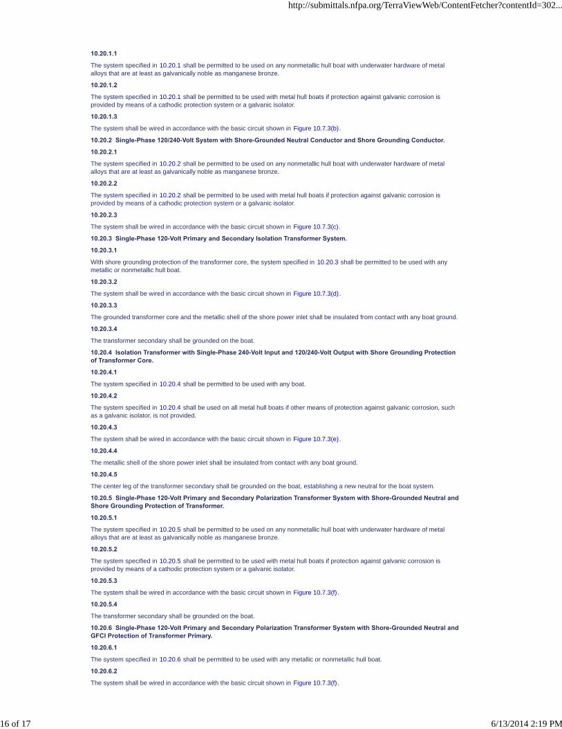
10.20.1.1
The system specified in 10.20.1 shall be permitted to be used on any nonmetallic hull boat with underwater hardware of metalalloys that are at least as galvanically noble as manganese bronze.
10.20.1.2
The system specified in 10.20.1 shall be permitted to be used with metal hull boats if protection against galvanic corrosion isprovided by means of a cathodic protection system or a galvanic isolator.
10.20.1.3
The system shall be wired in accordance with the basic circuit shown in Figure 10.7.3(b).
10.20.2 Single-Phase 120/240-Volt System with Shore-Grounded Neutral Conductor and Shore Grounding Conductor.
10.20.2.1
The system specified in 10.20.2 shall be permitted to be used on any nonmetallic hull boat with underwater hardware of metalalloys that are at least as galvanically noble as manganese bronze.
10.20.2.2
The system specified in 10.20.2 shall be permitted to be used with metal hull boats if protection against galvanic corrosion isprovided by means of a cathodic protection system or a galvanic isolator.
10.20.2.3
The system shall be wired in accordance with the basic circuit shown in Figure 10.7.3(c).
10.20.3 Single-Phase 120-Volt Primary and Secondary Isolation Transformer System.
10.20.3.1
With shore grounding protection of the transformer core, the system specified in 10.20.3 shall be permitted to be used with anymetallic or nonmetallic hull boat.
10.20.3.2
The system shall be wired in accordance with the basic circuit shown in Figure 10.7.3(d).
10.20.3.3
The grounded transformer core and the metallic shell of the shore power inlet shall be insulated from contact with any boat ground.
10.20.3.4
The transformer secondary shall be grounded on the boat.
10.20.4 Isolation Transformer with Single-Phase 240-Volt Input and 120/240-Volt Output with Shore Grounding Protectionof Transformer Core.
10.20.4.1
The system specified in 10.20.4 shall be permitted to be used with any boat.
10.20.4.2
The system specified in 10.20.4 shall be used on all metal hull boats if other means of protection against galvanic corrosion, suchas a galvanic isolator, is not provided.
10.20.4.3
The system shall be wired in accordance with the basic circuit shown in Figure 10.7.3(e).
10.20.4.4
The metallic shell of the shore power inlet shall be insulated from contact with any boat ground.
10.20.4.5
The center leg of the transformer secondary shall be grounded on the boat, establishing a new neutral for the boat system.
10.20.5 Single-Phase 120-Volt Primary and Secondary Polarization Transformer System with Shore-Grounded Neutral andShore Grounding Protection of Transformer.
10.20.5.1
The system specified in 10.20.5 shall be permitted to be used on any nonmetallic hull boat with underwater hardware of metalalloys that are at least as galvanically noble as manganese bronze.
10.20.5.2
The system specified in 10.20.5 shall be permitted to be used with metal hull boats if protection against galvanic corrosion isprovided by means of a cathodic protection system or a galvanic isolator.
10.20.5.3
The system shall be wired in accordance with the basic circuit shown in Figure 10.7.3(f) .
10.20.5.4
The transformer secondary shall be grounded on the boat.
10.20.6 Single-Phase 120-Volt Primary and Secondary Polarization Transformer System with Shore-Grounded Neutral andGFCI Protection of Transformer Primary.
10.20.6.1
The system specified in 10.20.6 shall be permitted to be used with any metallic or nonmetallic hull boat.
10.20.6.2
The system shall be wired in accordance with the basic circuit shown in Figure 10.7.3(f) .
http://submittals.nfpa.org/TerraViewWeb/ContentFetcher?contentId=302...
16 of 17 6/13/2014 2:19 PM

PIs [1] FR-26 Hide Legislative
10.20.6.3
The metallic shell of the shore power inlet shall be insulated from contact with any boat ground.
10.20.6.4
The transformer secondary shall be grounded on the boat.
10.20.7 Single-Phase Isolation Transformer with 240-Volt Input and 120/240-Volt Secondary with GFCI Protection ofTransformer Primary.
10.20.7.1
The system specified in 10.20.7 shall be permitted to be used with any metallic or nonmetallic hull boat.
10.20.7.2
The system shall be wired in accordance with the basic circuit shown in Figure 10.7.3(g).
10.20.7.3
The metallic shell of the shore power inlet shall be insulated from contact with any boat ground.
10.20.7.4
The central leg of the transformer secondary shall be grounded on the boat, establishing a new neutral for the boat system.
10.20.8 Single-Phase Polarization Transformer with 240-Volt Input and 120/240-Volt Secondary and Shore GroundingConductor Protection of Transformer Core.
10.20.8.1
The system specified in 10.20.8 shall be permitted to be used on any nonmetallic hull boat with underwater hardware of metalalloys that are at least as galvanically noble as manganese bronze.
10.20.8.2
The system specified in 10.20.8 shall be permitted to be used with metal hull boats if protection against galvanic corrosion isprovided by means of a cathodic protection system or a galvanic isolator.
10.20.8.3
The system shall be wired in accordance with the basic circuit shown in Figure 10.7.3(e).
10.20.8.4
The center leg of the transformer secondary shall be grounded on the boat, establishing a new neutral for the boat system.
Global FR-26 Hide Deleted
10.20.8.5
Ground-fault protection equipment shall be installed in the main shore power conductors with or in addtiion to the main shorepower disconnect circuit breaker(s) aboard the vessel.
10.20.8.5.1
The device trip level shall be a maximum of 30mA and the trip time shall be a maximum of 100mS. The device shall be readilyaccessible.
http://submittals.nfpa.org/TerraViewWeb/ContentFetcher?contentId=302...
17 of 17 6/13/2014 2:19 PM

NFPA 302®, Fire Protection Standard for Pleasure and Commercial Motor Craft, 2010 Edition
NFPA STANDARDS DEVELOPMENT SITEFIRST DRAFT REPORTClosing Date: February 22, 2013 NOTE: All Public Comment must be received by 5:00 pm EST/EDST on the published Closing Date.
Quick PrintChapter 11 Lightning Protection
11.1 General.
Lightning protection systems shall follow the guidelines in ABYC TE-4, Lightning Protection.
http://submittals.nfpa.org/TerraViewWeb/ContentFetcher?contentId=302...
1 of 1 6/13/2014 2:19 PM
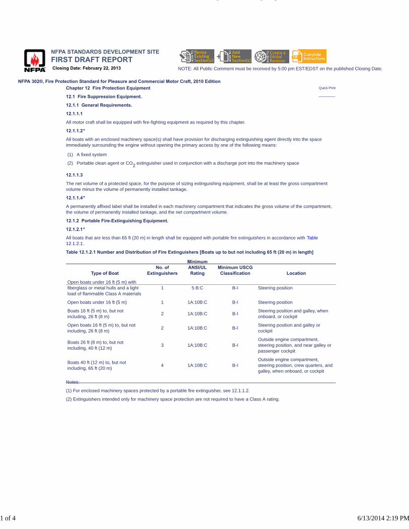
NFPA 302®, Fire Protection Standard for Pleasure and Commercial Motor Craft, 2010 Edition
NFPA STANDARDS DEVELOPMENT SITEFIRST DRAFT REPORTClosing Date: February 22, 2013 NOTE: All Public Comment must be received by 5:00 pm EST/EDST on the published Closing Date.
Quick PrintChapter 12 Fire Protection Equipment
12.1 Fire Suppression Equipment.
12.1.1 General Requirements.
12.1.1.1
All motor craft shall be equipped with fire-fighting equipment as required by this chapter.
12.1.1.2*
All boats with an enclosed machinery space(s) shall have provision for discharging extinguishing agent directly into the spaceimmediately surrounding the engine without opening the primary access by one of the following means:
(1) A fixed system
(2) Portable clean agent or CO2 extinguisher used in conjunction with a discharge port into the machinery space
12.1.1.3
The net volume of a protected space, for the purpose of sizing extinguishing equipment, shall be at least the gross compartmentvolume minus the volume of permanently installed tankage.
12.1.1.4*
A permanently affixed label shall be installed in each machinery compartment that indicates the gross volume of the compartment,the volume of permanently installed tankage, and the net compartment volume.
12.1.2 Portable Fire-Extinguishing Equipment.
12.1.2.1*
All boats that are less than 65 ft (20 m) in length shall be equipped with portable fire extinguishers in accordance with Table12.1.2.1.
Table 12.1.2.1 Number and Distribution of Fire Extinguishers [Boats up to but not including 65 ft (20 m) in length]
Type of BoatNo. of
Extinguishers
MinimumANSI/ULRating
Minimum USCGClassification Location
Open boats under 16 ft (5 m) withfiberglass or metal hulls and a lightload of flammable Class A materials
1 5 B:C B-I Steering position
Open boats under 16 ft (5 m) 1 1A:10B:C B-I Steering position
Boats 16 ft (5 m) to, but notincluding, 26 ft (8 m)
2 1A:10B:C B-ISteering position and galley, whenonboard, or cockpit
Open boats 16 ft (5 m) to, but notincluding, 26 ft (8 m)
2 1A:10B:C B-ISteering position and galley orcockpit
Boats 26 ft (8 m) to, but notincluding, 40 ft (12 m)
3 1A:10B:C B-IOutside engine compartment,steering position, and near galley orpassenger cockpit
Boats 40 ft (12 m) to, but notincluding, 65 ft (20 m)
4 1A:10B:C B-IOutside engine compartment,steering position, crew quarters, andgalley, when onboard, or cockpit
Notes:
(1) For enclosed machinery spaces protected by a portable fire extinguisher, see 12.1.1.2.
(2) Extinguishers intended only for machinery space protection are not required to have a Class A rating.
http://submittals.nfpa.org/TerraViewWeb/ContentFetcher?contentId=302...
1 of 4 6/13/2014 2:19 PM

CIs [1]
12.1.2.2
All boats that are equal to or greater than 65 ft (20 m) in length shall be equipped with portable fire extinguishers in accordance withTable 12.1.2.2.
Table 12.1.2.2 Number and Distribution of Fire Extinguishers [Boats equal to and greater than 65 ft (20 m) in length]
Gross TonnageNo. of
ExtinguishersMinimum ANSI/UL
RatingMinimum USCGClassification Location
Under 50 1* 4A:60B:C B-II Outside machinery space
1 4A:60B:C B-II Helmsman's position
3 1A:10B:C B-I Galley, crew quarters, and cabin
50 to less than100
1* 4A:60B:C B-II Outside machinery space
2 4A:60B:C B-II Helmsman's position and galley
2 1A:10B:C B-I Crew quarters and cabin
100 to less than300
1* 4A:60B:C B-II Outside machinery space
3 4A:60B:C B-IIHelmsman's position, galley, andcrew quarters
1 1A:10B:C B-I Cabin
* If the total horsepower exceeds 1000 bhp, an additional Type B-II portable fire extinguisher is required for each additional 1000bhp or fraction thereof.
12.1.2.3*
Portable fire extinguishers, other than those addressed in 12.1.2.6, shall meet the requirements of, and be inspected andmaintained in accordance with, NFPA 10, Standard for Portable Fire Extinguishers.
12.1.2.4
Portable fire extinguishers, other than those addressed in 12.1.2.6, shall be U.S. Coast Guard–approved.
12.1.2.5
All required portable fire extinguishers located in accommodation spaces shall have Class A capability.
12.1.2.6
A bucket with attached lanyard shall be considered a Class A–rated portable fire extinguisher on boats under 26 ft (8 m) in lengththat do not have enclosed accommodation spaces or enclosed galleys.
12.1.2.7
It shall not be necessary to travel more than half the length of the vessel or 33 ft (10 m), whichever is less, to reach an extinguisher.
12.1.2.8* Enclosed Machinery Spaces Protected by a Portable Extinguisher.
12.1.2.8.1
Enclosed machinery spaces protected by a portable extinguisher shall be provided with a readily accessible port that is sized toaccept the extinguisher nozzle and marked as to its function.
12.1.2.8.2
The port required by 12.1.2.8.1 shall be located so that the extinguisher can remain upright during discharge unless theextinguisher is equipped with a discharge hose.
http://submittals.nfpa.org/TerraViewWeb/ContentFetcher?contentId=302...
2 of 4 6/13/2014 2:19 PM

PIs [1]
CIs [1]
12.1.2.8.3
Where portable equipment is provided for enclosed machinery space protection, the size and type shall be as specified in Table12.1.2.8.3.
Table 12.1.2.8.3 Minimum Clean Agent or CO2 Portable Extinguisher Sizes for Flooding an Enclosed Machinery Space
Minimum Extinguisher Size Maximum Compartment Volume
Agent lb kg ft3 m3
CO2 5 2.3 66 2
CO2 10 4.5 133 4
CO2 15 7 200 6
CO2 20 9 266 7.5
Halogenated agent 2.5 1 108 3
Halogenated agent 3 1.4 130 3.7
Halogenated agent 4 2 174 5
Halogenated agent 5 2.3 217 6
Halogenated agent 9 4 391 11
Halogenated agent 13 6 565 16
HFC-227ea 5.75 2.5 125 3.5
HFC-227ea 10.75 5 250 7.1
12.1.2.8.4
If an extinguisher is portable and readily removable from its fixed mounting, it shall be permitted to be credited as one of theextinguishers required in Table 12.1.2.1 or Table 12.1.2.2.
12.1.2.9 Installation of Portable Extinguishers.
12.1.2.9.1
Portable fire extinguishers shall be located near the means of egress and be readily accessible to the compartment that they areintended to serve.
12.1.2.9.2
Extinguishers shall be mounted with the marine bracket specified on the extinguisher label.
12.1.2.9.3
At least one extinguisher shall be located at each occupied level.
12.1.3* Fixed Fire Protection Systems.
12.1.3.1
Systems shall be manually and automatically operated.
12.1.3.2
Carbon dioxide, Halon 1211, and HCFC-124 systems that are installed to protect accommodation compartments or to protectnormally occupied enclosed machinery spaces shall be equipped with a predischarge alarm.
12.1.3.3 Connected Spaces.
12.1.3.3.1
If spaces are connected as determined by 4.4.1(5), such spaces shall be considered as a single space when determining therequired capacity of the system.
12.1.3.3.2
The actuation of the system shall be such that all the connecting spaces are flooded.
12.1.3.3.3
If multiple units are used to provide the required capacity for connecting spaces, they shall discharge simultaneously.
12.1.3.4*
Fixed systems shall comply with the following criteria:
(1) They shall meet the requirements of the manufacturer's instructions.
(2) They shall meet the requirements of NFPA 12, Standard on Carbon Dioxide Extinguishing Systems; NFPA 12A, Standard onHalon 1301 Fire Extinguishing Systems; NFPA 2001, Standard on Clean Agent Fire Extinguishing Systems; or NFPA 2010,Standard for Fixed Aerosol Fire-Extinguishing Systems, as appropriate, and shall be listed to the applicable ANSI/UL marinestandard.
(3) For installation on pleasure craft, they shall be U.S. Coast Guard–approved.
http://submittals.nfpa.org/TerraViewWeb/ContentFetcher?contentId=302...
3 of 4 6/13/2014 2:19 PM
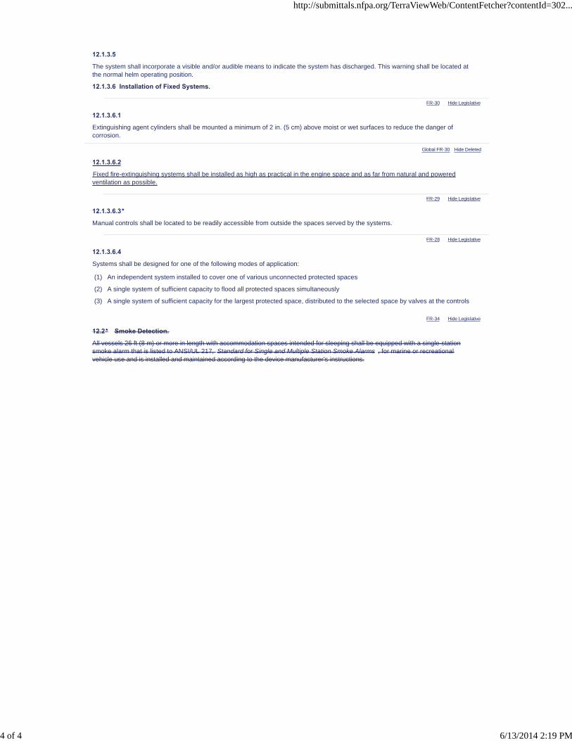
FR-30 Hide Legislative
FR-29 Hide Legislative
FR-28 Hide Legislative
FR-34 Hide Legislative
12.1.3.5
The system shall incorporate a visible and/or audible means to indicate the system has discharged. This warning shall be located atthe normal helm operating position.
12.1.3.6 Installation of Fixed Systems.
12.1.3.6.1
Extinguishing agent cylinders shall be mounted a minimum of 2 in. (5 cm) above moist or wet surfaces to reduce the danger ofcorrosion.
Global FR-30 Hide Deleted
12.1.3.6.2
Fixed fire-extinguishing systems shall be installed as high as practical in the engine space and as far from natural and poweredventilation as possible.
12.1.3.6.3*
Manual controls shall be located to be readily accessible from outside the spaces served by the systems.
12.1.3.6.4
Systems shall be designed for one of the following modes of application:
(1) An independent system installed to cover one of various unconnected protected spaces
(2) A single system of sufficient capacity to flood all protected spaces simultaneously
(3) A single system of sufficient capacity for the largest protected space, distributed to the selected space by valves at the controls
12.2* Smoke Detection.
All vessels 26 ft (8 m) or more in length with accommodation spaces intended for sleeping shall be equipped with a single-stationsmoke alarm that is listed to ANSI/UL 217, Standard for Single and Multiple Station Smoke Alarms , for marine or recreationalvehicle use and is installed and maintained according to the device manufacturer's instructions.
http://submittals.nfpa.org/TerraViewWeb/ContentFetcher?contentId=302...
4 of 4 6/13/2014 2:19 PM

NFPA 302®, Fire Protection Standard for Pleasure and Commercial Motor Craft, 2010 Edition
NFPA STANDARDS DEVELOPMENT SITEFIRST DRAFT REPORTClosing Date: February 22, 2013 NOTE: All Public Comment must be received by 5:00 pm EST/EDST on the published Closing Date.
Quick Print
PIs [1]
FR-33 Hide Legislative
FR-35 Hide Legislative
Chapter 13 Carbon Monoxide Detection
13.1* Carbon Monoxide and Smoke Detection Systems.
A carbon monoxide detection system shall be installed on all boats with an enclosed accommodation compartment(s) and agasoline generator set, or an inboard gasoline propulsion engine.
13.2 Installation.
Carbon monoxide detection systems and installation shall meet the requirements of ABYC A-24, Carbon Monoxide DetectionSystems.
Global FR-35 Hide Deleted
13.3* Smoke Detection.
All vessels with accommodation spaces intended for sleeping shall be equipped with a single-station smoke alarm that is listed toANSI/UL 217, Standard for Single and Multiple Station Smoke Alarms , for marine or recreational vehicle use and is installed andmaintained according to the device manufacturer's instructions.
http://submittals.nfpa.org/TerraViewWeb/ContentFetcher?contentId=302...
1 of 1 6/13/2014 2:20 PM

NFPA 302®, Fire Protection Standard for Pleasure and Commercial Motor Craft, 2010 Edition
NFPA STANDARDS DEVELOPMENT SITEFIRST DRAFT REPORTClosing Date: February 22, 2013 NOTE: All Public Comment must be received by 5:00 pm EST/EDST on the published Closing Date.
Quick Print
FR-41 Hide Legislative
Annex A Explanatory Material
Annex A is not a part of the requirements of this NFPA document but is included for informational purposes only. This annexcontains explanatory material, numbered to correspond with the applicable text paragraphs.
A.1.6
For additional conversion information, see ASTM SI 10, Standard for Use of the International System of Units (SI): The ModernMetric System IEEE/ASTM SI 10, American National Standard for Use of the International System of Units (SI): The ModernMetric SystemMetric Practice , 2010 edition .
A.3.2.1 Approved.
The National Fire Protection Association does not approve, inspect, or certify any installations, procedures, equipment, or materials;nor does it approve or evaluate testing laboratories. In determining the acceptability of installations, procedures, equipment, ormaterials, the authority having jurisdiction may base acceptance on compliance with NFPA or other appropriate standards. In theabsence of such standards, said authority may require evidence of proper installation, procedure, or use. The authority havingjurisdiction may also refer to the listings or labeling practices of an organization that is concerned with product evaluations and isthus in a position to determine compliance with appropriate standards for the current production of listed items.
A.3.2.2 Authority Having Jurisdiction (AHJ).
The phrase “authority having jurisdiction,” or its acronym AHJ, is used in NFPA documents in a broad manner, since jurisdictionsand approval agencies vary, as do their responsibilities. Where public safety is primary, the authority having jurisdiction may be afederal, state, local, or other regional department or individual such as a fire chief; fire marshal; chief of a fire prevention bureau,labor department, or health department; building official; electrical inspector; or others having statutory authority. For insurancepurposes, an insurance inspection department, rating bureau, or other insurance company representative may be the authorityhaving jurisdiction. In many circumstances, the property owner or his or her designated agent assumes the role of the authorityhaving jurisdiction; at government installations, the commanding officer or departmental official may be the authority havingjurisdiction.
A.3.2.4 Listed.
The means for identifying listed equipment may vary for each organization concerned with product evaluation; some organizationsdo not recognize equipment as listed unless it is also labeled. The authority having jurisdiction should utilize the system employedby the listing organization to identify a listed product.
A.3.3.8 Clean Agent.
Although commonly referred to as a clean agent in the marine industry, for the purposes of NFPA standards, CO2 is not considered
a clean agent.
A.3.3.9 Compressed Natural Gas (CNG).
Mixtures of hydrocarbon gases and vapors, consisting principally of methane in gaseous form that has been compressed for use asa fuel.
A.3.3.11 Engine Exhaust System.
This system includes related accessories that can be metallic or nonmetallic, such as pipes, mufflers, silencers, turbochargers,spark arresters, and all necessary connecting and supporting fittings. Wet exhaust systems are provided with water injection intothe exhaust gas stream; dry exhaust systems do not have this provision.
http://submittals.nfpa.org/TerraViewWeb/ContentFetcher?contentId=302...
1 of 15 6/13/2014 2:20 PM
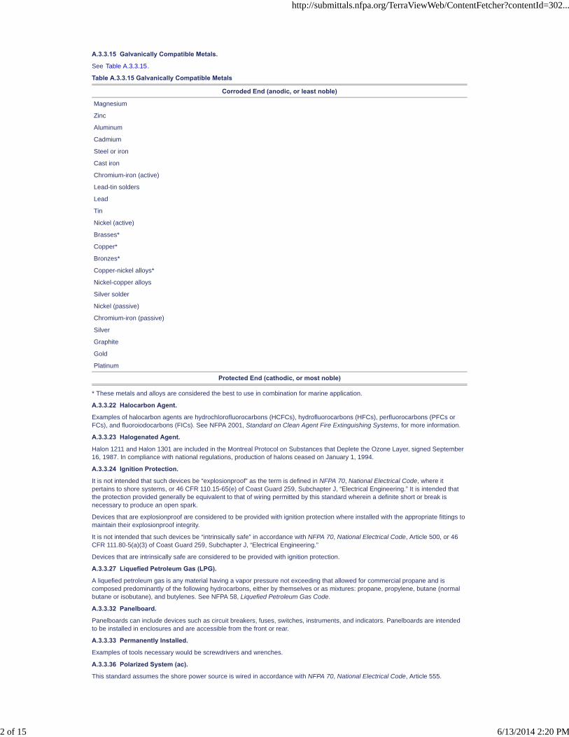
A.3.3.15 Galvanically Compatible Metals.
See Table A.3.3.15.
Table A.3.3.15 Galvanically Compatible Metals
Corroded End (anodic, or least noble)
Magnesium
Zinc
Aluminum
Cadmium
Steel or iron
Cast iron
Chromium-iron (active)
Lead-tin solders
Lead
Tin
Nickel (active)
Brasses*
Copper*
Bronzes*
Copper-nickel alloys*
Nickel-copper alloys
Silver solder
Nickel (passive)
Chromium-iron (passive)
Silver
Graphite
Gold
Platinum
Protected End (cathodic, or most noble)
* These metals and alloys are considered the best to use in combination for marine application.
A.3.3.22 Halocarbon Agent.
Examples of halocarbon agents are hydrochlorofluorocarbons (HCFCs), hydrofluorocarbons (HFCs), perfluorocarbons (PFCs orFCs), and fluoroiodocarbons (FICs). See NFPA 2001, Standard on Clean Agent Fire Extinguishing Systems, for more information.
A.3.3.23 Halogenated Agent.
Halon 1211 and Halon 1301 are included in the Montreal Protocol on Substances that Deplete the Ozone Layer, signed September16, 1987. In compliance with national regulations, production of halons ceased on January 1, 1994.
A.3.3.24 Ignition Protection.
It is not intended that such devices be “explosionproof” as the term is defined in NFPA 70, National Electrical Code, where itpertains to shore systems, or 46 CFR 110.15-65(e) of Coast Guard 259, Subchapter J, “Electrical Engineering.” It is intended thatthe protection provided generally be equivalent to that of wiring permitted by this standard wherein a definite short or break isnecessary to produce an open spark.
Devices that are explosionproof are considered to be provided with ignition protection where installed with the appropriate fittings tomaintain their explosionproof integrity.
It is not intended that such devices be “intrinsically safe” in accordance with NFPA 70, National Electrical Code, Article 500, or 46CFR 111.80-5(a)(3) of Coast Guard 259, Subchapter J, “Electrical Engineering.”
Devices that are intrinsically safe are considered to be provided with ignition protection.
A.3.3.27 Liquefied Petroleum Gas (LPG).
A liquefied petroleum gas is any material having a vapor pressure not exceeding that allowed for commercial propane and iscomposed predominantly of the following hydrocarbons, either by themselves or as mixtures: propane, propylene, butane (normalbutane or isobutane), and butylenes. See NFPA 58, Liquefied Petroleum Gas Code.
A.3.3.32 Panelboard.
Panelboards can include devices such as circuit breakers, fuses, switches, instruments, and indicators. Panelboards are intendedto be installed in enclosures and are accessible from the front or rear.
A.3.3.33 Permanently Installed.
Examples of tools necessary would be screwdrivers and wrenches.
A.3.3.36 Polarized System (ac).
This standard assumes the shore power source is wired in accordance with NFPA 70, National Electrical Code, Article 555.
http://submittals.nfpa.org/TerraViewWeb/ContentFetcher?contentId=302...
2 of 15 6/13/2014 2:20 PM
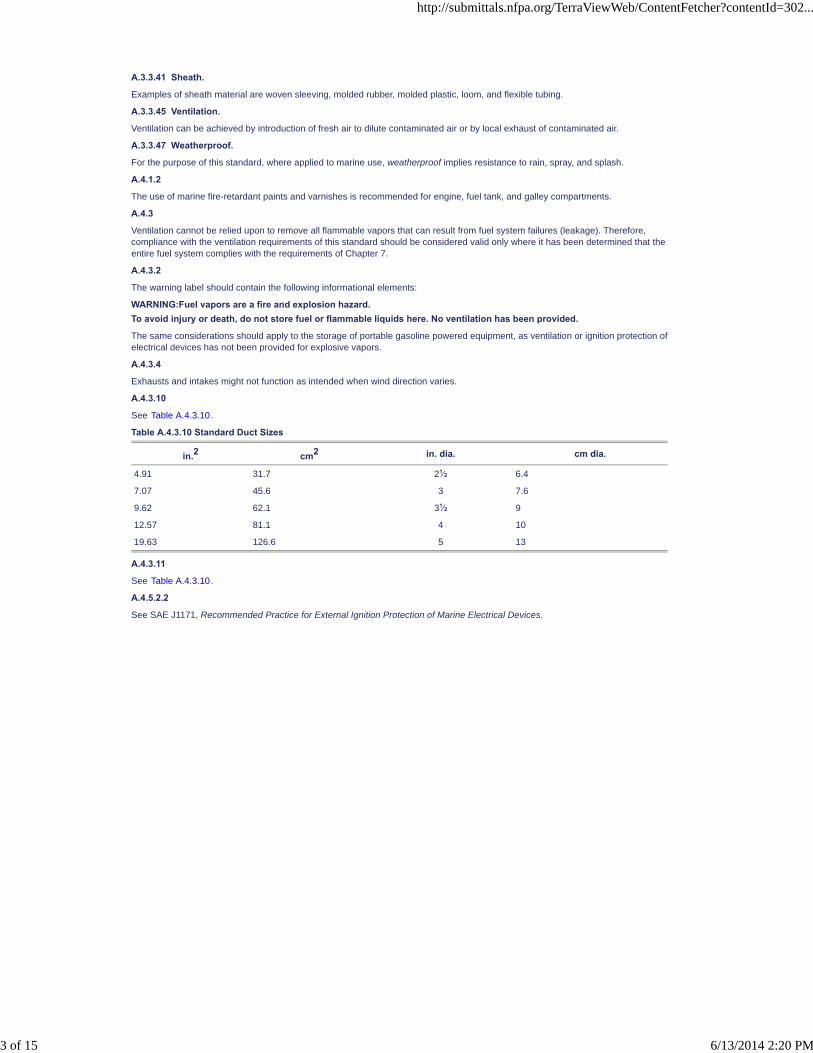
A.3.3.41 Sheath.
Examples of sheath material are woven sleeving, molded rubber, molded plastic, loom, and flexible tubing.
A.3.3.45 Ventilation.
Ventilation can be achieved by introduction of fresh air to dilute contaminated air or by local exhaust of contaminated air.
A.3.3.47 Weatherproof.
For the purpose of this standard, where applied to marine use, weatherproof implies resistance to rain, spray, and splash.
A.4.1.2
The use of marine fire-retardant paints and varnishes is recommended for engine, fuel tank, and galley compartments.
A.4.3
Ventilation cannot be relied upon to remove all flammable vapors that can result from fuel system failures (leakage). Therefore,compliance with the ventilation requirements of this standard should be considered valid only where it has been determined that theentire fuel system complies with the requirements of Chapter 7.
A.4.3.2
The warning label should contain the following informational elements:
WARNING:Fuel vapors are a fire and explosion hazard.To avoid injury or death, do not store fuel or flammable liquids here. No ventilation has been provided.
The same considerations should apply to the storage of portable gasoline powered equipment, as ventilation or ignition protection ofelectrical devices has not been provided for explosive vapors.
A.4.3.4
Exhausts and intakes might not function as intended when wind direction varies.
A.4.3.10
See Table A.4.3.10.
Table A.4.3.10 Standard Duct Sizes
in.2 cm2 in. dia. cm dia.
4.91 31.7 21⁄2 6.4
7.07 45.6 3 7.6
9.62 62.1 31⁄2 9
12.57 81.1 4 10
19.63 126.6 5 13
A.4.3.11
See Table A.4.3.10.
A.4.5.2.2
See SAE J1171, Recommended Practice for External Ignition Protection of Marine Electrical Devices.
http://submittals.nfpa.org/TerraViewWeb/ContentFetcher?contentId=302...
3 of 15 6/13/2014 2:20 PM

FR-52 Hide Legislative
A.4.6.3
These drawings only provide examples of the location and orientation necessary to prevent entry of fuel vapors. They do notsupersede the requirements of 7.5.2 addressing the escape of liquid and vapor overflow. See Figure A.4.6.3.
Figure A.4.6.3 Examples of How to Measure Ventilation Opening Separation from Fuel Fill or Vent Fitting.
A.4.7
Consult the engine manufacturer(s) for combustion air requirements, including inlet air temperature and restriction/depression.
A.5.3
See SAE J1223, Recommended Practice for Marine Carburetors and Fuel Injection Throttle Bodies.
A.5.3.3
See SAE J1223, Recommended Practice for Marine Carburetors and Fuel Injection Throttle Bodies.
A.5.8
See SAE J1191, Recommended Practice for High Tension Ignition Cable Assemblies—Marine.
A.5.9
For information on ignition distributors, see SAE J1294, Recommended Practice for Ignition Distributors—Marine.
A.7.2.2.5.3
Brackets will reduce the chance of crevice and pitting corrosion of the tank surfaces by ensuring air circulation to the tank surfaces.
A.7.5.1.7
Nonmetallic fuel system components degrade when exposed to ultraviolet (UV) radiation (i.e., sunlight). Such components that willbe exposed to UV radiation should be chosen for their UV resistance and should be inspected periodically to determine suitabilityfor continued service.
A.7.5.2.4
An inverted “U” bend in the fuel tank vent pipe is one way to minimize the intake of water.
A.7.5.2.9
The purpose of this requirement is to preserve the fuel tightness at either end of the flexible section.
A.7.5.3
If fuel tanks are located in a compartment other than the engine compartment, or if the engine and fuel tanks are separated by adistance of more than 12 ft (3.7 m), an approved manual stop valve should be installed at the engine end of the fuel line to stop fuelflow when the engine is being serviced.
A.7.5.3.1
The purpose of the 12 in. (30 cm) requirement is to minimize the amount of pressurized piping when the pump is operating.
http://submittals.nfpa.org/TerraViewWeb/ContentFetcher?contentId=302...
4 of 15 6/13/2014 2:20 PM
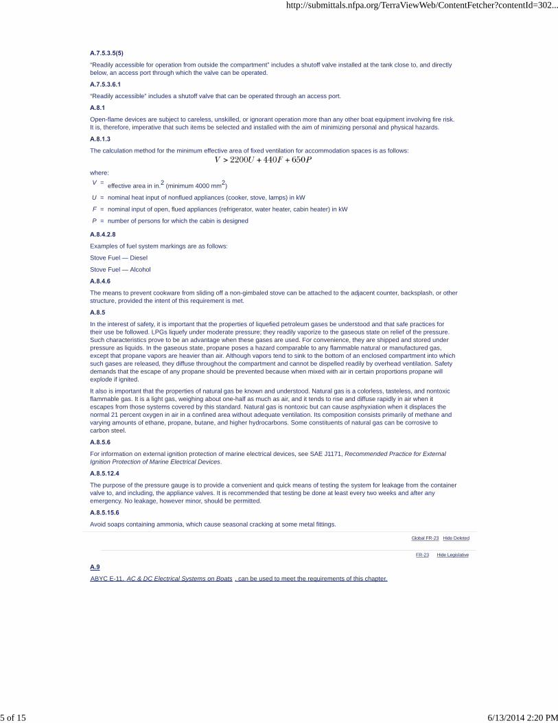
FR-23 Hide Legislative
A.7.5.3.5(5)
“Readily accessible for operation from outside the compartment” includes a shutoff valve installed at the tank close to, and directlybelow, an access port through which the valve can be operated.
A.7.5.3.6.1
“Readily accessible” includes a shutoff valve that can be operated through an access port.
A.8.1
Open-flame devices are subject to careless, unskilled, or ignorant operation more than any other boat equipment involving fire risk.It is, therefore, imperative that such items be selected and installed with the aim of minimizing personal and physical hazards.
A.8.1.3
The calculation method for the minimum effective area of fixed ventilation for accommodation spaces is as follows:
where:
V = effective area in in.2 (minimum 4000 mm2)
U = nominal heat input of nonflued appliances (cooker, stove, lamps) in kW
F = nominal input of open, flued appliances (refrigerator, water heater, cabin heater) in kW
P = number of persons for which the cabin is designed
A.8.4.2.8
Examples of fuel system markings are as follows:
Stove Fuel — Diesel
Stove Fuel — Alcohol
A.8.4.6
The means to prevent cookware from sliding off a non-gimbaled stove can be attached to the adjacent counter, backsplash, or otherstructure, provided the intent of this requirement is met.
A.8.5
In the interest of safety, it is important that the properties of liquefied petroleum gases be understood and that safe practices fortheir use be followed. LPGs liquefy under moderate pressure; they readily vaporize to the gaseous state on relief of the pressure.Such characteristics prove to be an advantage when these gases are used. For convenience, they are shipped and stored underpressure as liquids. In the gaseous state, propane poses a hazard comparable to any flammable natural or manufactured gas,except that propane vapors are heavier than air. Although vapors tend to sink to the bottom of an enclosed compartment into whichsuch gases are released, they diffuse throughout the compartment and cannot be dispelled readily by overhead ventilation. Safetydemands that the escape of any propane should be prevented because when mixed with air in certain proportions propane willexplode if ignited.
It also is important that the properties of natural gas be known and understood. Natural gas is a colorless, tasteless, and nontoxicflammable gas. It is a light gas, weighing about one-half as much as air, and it tends to rise and diffuse rapidly in air when itescapes from those systems covered by this standard. Natural gas is nontoxic but can cause asphyxiation when it displaces thenormal 21 percent oxygen in air in a confined area without adequate ventilation. Its composition consists primarily of methane andvarying amounts of ethane, propane, butane, and higher hydrocarbons. Some constituents of natural gas can be corrosive tocarbon steel.
A.8.5.6
For information on external ignition protection of marine electrical devices, see SAE J1171, Recommended Practice for ExternalIgnition Protection of Marine Electrical Devices.
A.8.5.12.4
The purpose of the pressure gauge is to provide a convenient and quick means of testing the system for leakage from the containervalve to, and including, the appliance valves. It is recommended that testing be done at least every two weeks and after anyemergency. No leakage, however minor, should be permitted.
A.8.5.15.6
Avoid soaps containing ammonia, which cause seasonal cracking at some metal fittings.
Global FR-23 Hide Deleted
A.9
ABYC E-11, AC & DC Electrical Systems on Boats , can be used to meet the requirements of this chapter.
http://submittals.nfpa.org/TerraViewWeb/ContentFetcher?contentId=302...
5 of 15 6/13/2014 2:20 PM

A.9.2.2
http://submittals.nfpa.org/TerraViewWeb/ContentFetcher?contentId=302...
6 of 15 6/13/2014 2:20 PM
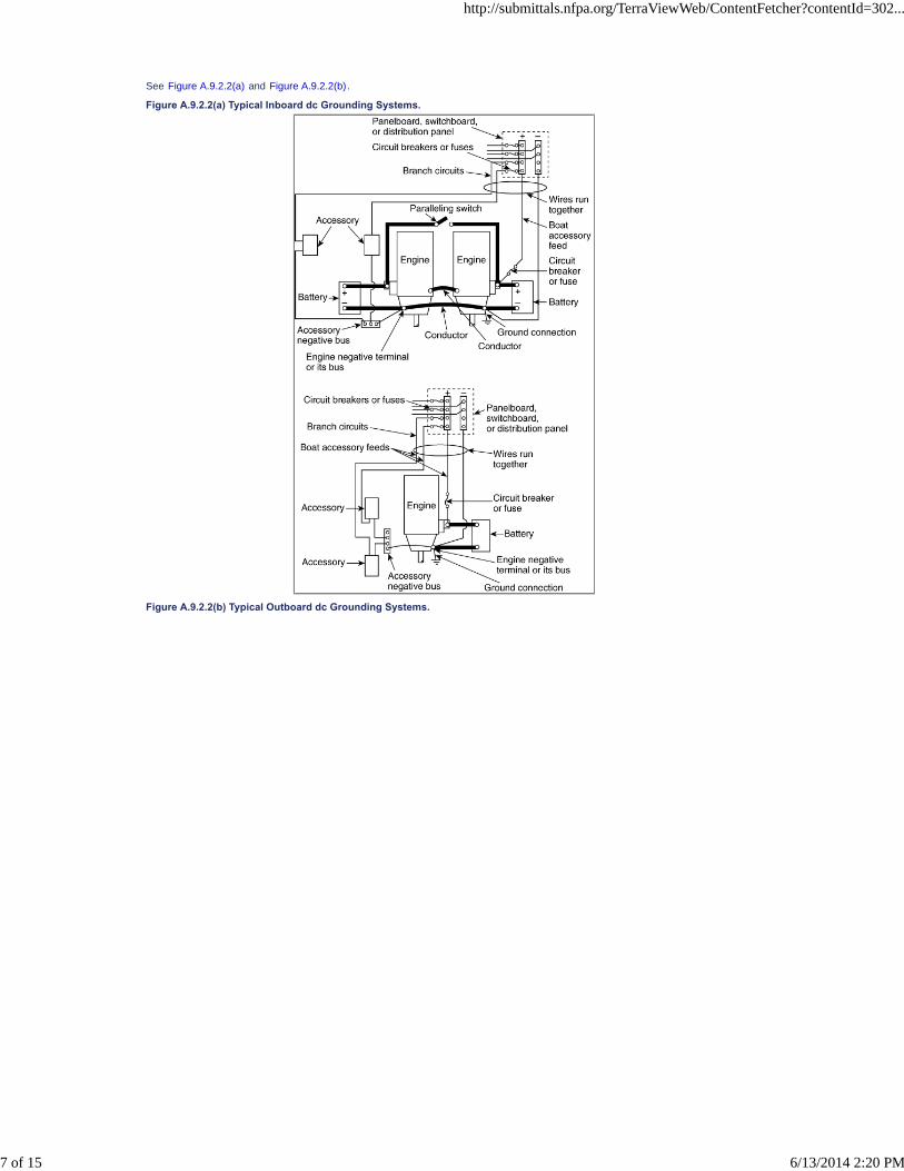
See Figure A.9.2.2(a) and Figure A.9.2.2(b) .
Figure A.9.2.2(a) Typical Inboard dc Grounding Systems.
Figure A.9.2.2(b) Typical Outboard dc Grounding Systems.
http://submittals.nfpa.org/TerraViewWeb/ContentFetcher?contentId=302...
7 of 15 6/13/2014 2:20 PM

A.9.3.3
These provisions also apply to installations of sealed batteries.
A.9.3.5
For information on securing batteries, see 33 CFR 183.
A.9.3.9
For information on shielding with dielectric material, see 33 CFR 183.
A.9.6.2
An engine is an example of electrical equipment that must be marked.
http://submittals.nfpa.org/TerraViewWeb/ContentFetcher?contentId=302...
8 of 15 6/13/2014 2:20 PM

A.9.8.2
http://submittals.nfpa.org/TerraViewWeb/ContentFetcher?contentId=302...
9 of 15 6/13/2014 2:20 PM
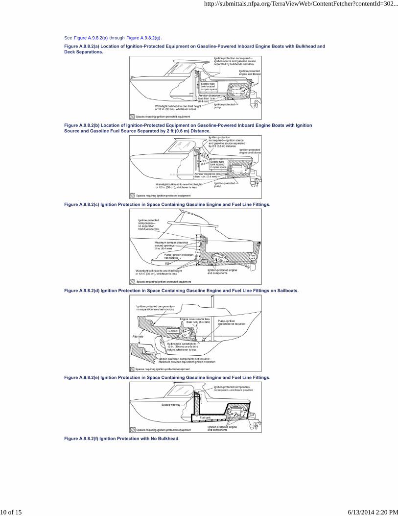
See Figure A.9.8.2(a) through Figure A.9.8.2(g) .
Figure A.9.8.2(a) Location of Ignition-Protected Equipment on Gasoline-Powered Inboard Engine Boats with Bulkhead andDeck Separations.
Figure A.9.8.2(b) Location of Ignition-Protected Equipment on Gasoline-Powered Inboard Engine Boats with IgnitionSource and Gasoline Fuel Source Separated by 2 ft (0.6 m) Distance.
Figure A.9.8.2(c) Ignition Protection in Space Containing Gasoline Engine and Fuel Line Fittings.
Figure A.9.8.2(d) Ignition Protection in Space Containing Gasoline Engine and Fuel Line Fittings on Sailboats.
Figure A.9.8.2(e) Ignition Protection in Space Containing Gasoline Engine and Fuel Line Fittings.
Figure A.9.8.2(f) Ignition Protection with No Bulkhead.
http://submittals.nfpa.org/TerraViewWeb/ContentFetcher?contentId=302...
10 of 15 6/13/2014 2:20 PM

Figure A.9.8.2(g) Cutaway Illustration Showing Separation of Electrical Components from Gasoline Fuel Source.
A.9.9.2
See Figure A.9.9.2.
Figure A.9.9.2 Location of Overcurrent Protection for Conductors Served by Single or Dual Batteries or Without BatterySwitch or Starter Circuit.
A.9.9.3.1
Sealed-valve regulator (SVR) batteries (also known as gel cells) require thermal-sensing, voltage-regulating charging devices. Thisapplies to both electrically powered and engine-driven charging devices.
A.9.9.4.1
The requirement of 9.9.4.1 might necessitate the use of thermally responsive protection devices on the equipment or system if themotor is not capable of operating continuously at maximum possible loading.
http://submittals.nfpa.org/TerraViewWeb/ContentFetcher?contentId=302...
11 of 15 6/13/2014 2:20 PM

FR-53 Hide Legislative
FR-24 Hide Legislative
A.9.9.4.2
If it is necessary to test as installed in order to ensure compliance with the locked rotor requirement, then voltage drop due to wiresize and delay characteristics of the overcurrent protection device should be adjusted to protect the motor.
A.9.9.7
See Figure A.9.9.7.
Figure A.9.9.7 Illustration of Overcurrent Protection for Panelboards and Panelboard Feeder Conductors.
A.9.9.8(4)
For information on marine circuit breakers, see SAE J1428, Recommended Practice for Marine Circuit Breakers.
A.9.9.8(5)
For information on external ignition protection of marine electrical devices, see SAE J1171, Recommended Practice for ExternalIgnition Protection of Marine Electrical Devices.
A.9.9.9(3)
For information on external ignition protection of marine electrical devices, see SAE J1171, Recommended Practice for ExternalIgnition Protection of Marine Electrical Devices.
A.9.10.5
Consideration should be given to the selection of special switches for use with high-current inductive loads.
A.9.12.2
For information on marine engine wiring, see SAE J378, Recommended Practice for Marine Engine Propulsion System Wiring.
A.9.13.1
Current-carrying conductors should be routed as high as practicable above the bilge water level and other areas where water canaccumulate.
A.9.13.2
Conductors should be routed as far away as practicable from exhaust pipes and other heat sources.
A.9.13.3.2
Battery cables should be routed to minimize contact with nonmetallic fuel system components.
A.9.13.4.3
For additional information, see ABYC TH-22, Educational Information About Carbon Monoxide, and ABYC TH-23, Design,Construction, and Testing of Boats in Consideration of Carbon Monoxide.
A.9.14.7
If a connection is soldered, the flexibility of the wire is affected and can be subject to failure from movement. If a crimped connectionis soldered, it can reduce the mechanical strength of the joint.
Global FR-24 Hide Deleted
A.10
ABYC E-11, AC & DC Electrical Systems on Boats , can be used to meet the requirements of this chapter.
A.10.1
This standard recognizes that shore power voltage varies in different geographic areas. The selection of motor-operated equipmentshould consider this variation.
A.10.2.3.2
Examples of locations to which the neutral could be grounded are at the onboard generator, at an inverter, at the secondary of anisolation or polarization transformer, or through the shore power connection.
http://submittals.nfpa.org/TerraViewWeb/ContentFetcher?contentId=302...
12 of 15 6/13/2014 2:20 PM

FR-42 Hide Legislative
A.10.6.2
See A.9.8.2.
A.10.6.2(4)
Seepage of not more than 1⁄4 fl oz (7.4 ml) per hour is permitted below the water-resistant height. This includes bulkhead fasteningsand space around hatches, doors, access panels, and items passing through the bulkhead.
Openings above the water-resistant height cannot have more than 1⁄4 in. (6.4 mm) annular space around items passing through theopenings.
A.10.7.1
Reverse-polarity indicating devices respond to the reversal of an ungrounded conductor and the grounded (white) conductor onlywhen there is continuity of the grounding (green, or green with yellow stripe) conductor to shore.
Reverse-polarity indicating devices might not respond to reversals of an ungrounded conductor and the grounding (green, or greenwith yellow stripe) conductor, the grounded (white) conductor and the grounding (green, or green with yellow stripe) conductor, orthree-phase conductors.
A.10.8.2(4)
For information on marine circuit breakers, see SAE J1428, Recommended Practice for Marine Circuit Breakers.
A.10.8.2(5)
For information on external ignition protection of marine electrical devices, see SAE J1171, Recommended Practice for ExternalIgnition Protection of Marine Electrical Devices.
A.10.8.3(3)
For information on external ignition protection of marine electrical devices, see SAE J1171, Recommended Practice for ExternalIgnition Protection of Marine Electrical Devices.
A.10.9.2.1
Overcurrent protection should be located as close as practical to the source of power.
A.10.9.3
Overcurrent protection should be located as close as practical to the source of power.
A.10.11.4
This GFP breaker provides ground-fault protection for the primary winding of the transformer only.
A.10.14.4
If a connection is soldered, the flexibility of the wire is affected and can be subject to failure from movement. If a crimped connectionis soldered, it can reduce the mechanical strength of the joint.
A.10.14.9
Current-carrying conductors should be routed as high as practical above the bilge water level and other areas where water canaccumulate.
A.10.14.10
Conductors should be routed as far away as practicable from exhaust pipes and other heat sources.
A.10.15.7
See NFPA 70® , National Electrical Code® ; , E-8.12 of ABYC E-8 , Alternating Current (AC) Electrical Systems on Boats ABYCE-11, AC & DC Electrical Systems on Boats ; , and applicable UL standards, for additional information.
A.12.1.1.2
Engine room calculations and concentrations can be used for other spaces.
A.12.1.1.4
The label should include the following statement, “Fixed fire extinguisher systems must be suitable for compartment volume of XXX
ft3. This volume is based on gross compartment volume less permanently installed tankage in this compartment determined usingABYC A-4.” For boats built prior to the effective date of this standard, it might be necessary to obtain this information from the boatmanufacturer or to calculate this volume accurately.
A.12.1.2.1
On boats without Class A combustibles or accommodation spaces, a USCG Type B-I extinguisher having only B:C capabilitiesshould be used. For equivalent ratings, use Table A.12.1.2.1.
Table A.12.1.2.1 U.S. Coast Guard (USCG) Classification of Portable and Semiportable Fire Extinguishers
Classification Type
Halogenated Agent Carbon Dioxide Dry Chemical HFC-227ea
Size lb kg lb kg lb kg lb kg
B I 2.5 1.1 5 2.3 2 0.9 5.75 2.5
B II 10 4.5 15 6.8 10 4.5 —- —-
B III —- —- 35 16 20 9.1 —- —-
A.12.1.2.3
On boats without Class A combustibles or accommodation spaces, a USCG Type B-I extinguisher having only B:C capabilitiesshould be used. For equivalent ratings, see Table A.12.1.2.1. (See Annex B.)
http://submittals.nfpa.org/TerraViewWeb/ContentFetcher?contentId=302...
13 of 15 6/13/2014 2:20 PM

A.12.1.2.8
See A.12.1.1.2.
A.12.1.3
There are two basic types of clean agent fire extinguishing systems: engineered and pre-engineered.
Engineered fire-extinguishing systems consist of components designed or selected for a specific application to a specific vessel ormodel series. Pre-engineered fixed fire-extinguishing systems (packaged systems) consist of those designed to be installedaccording to pre-tested limitations.
In calculating the volumes of the space to be protected, all connecting compartments or spaces into which extinguishing vapor canmigrate easily, such as bilges, tank compartments, and storage areas, should be included. For information on connectingcompartments or spaces, see 4.2.1. All devices that consume air from the protected spaces should be shut down prior to or at thetime of system actuation.
Engineered systems, when installed in accordance with the U.S. Coast Guard–approved installation manual, provide adequateprotection for the volume specified in the approval documentation and the manual. A self-inspection form is available that should becompleted by the installer or the owner and returned to the manufacturer. The manufacturer then provides a certificate, which issubmitted to the authority having jurisdiction as evidence of an approved system.
Pre-engineered systems include an installation manual that also warns of their limitations. It is extremely important that theselimitations, as outlined below, be observed:
(1) Independently activated multiple units should not be used to provide protection for a volume larger than the smallest unitinstalled. If multiple self-contained units are installed in a single compartment, it is extremely unlikely that they will functionsimultaneously.
(2) Units should be located with their sensor near the top of the protected space.
Toxic products are produced in a fire event, and necessary precautions — such as ventilating the space and/or the wearing ofself-contained breathing apparatus — should be taken before entering the space.
A CO2 fixed system consists of the storage container, actuation controls, pressure switch, and nozzles. All devices that consume air
from the protected spaces should be shut down prior to or at the time of system actuation. Since this normally includes the mainpropulsion engine, it frequently is preferred that the system be actuated manually without automatic detection.
A.12.1.3.4
In the absence of a manufacturer's instruction manual, Table A.12.1.3.4 provides information that can be used to determine weightper maximum volume of space protected for carbon dioxide or clean agent. A new system should be installed and maintained inaccordance with the manufacturer's instructions and should be U.S. Coast Guard–approved or listed to the applicable ANSI/ULmarine standard.
Table A.12.1.3.4 Recommended Weight of Carbon Dioxide and Clean Agents for Pre-Engineered Systems
Maximum Volume of Space (Net) Carbon Dioxidea Halon 1211b Halon 1301b HFC-227eac HCFC-124d
ft3 m3 lb kg lb kg lb kg lb kg lb kg
<90 <2.5 5 2.3 2.1 0.9 1.9 0.8 3.9 1.7 3.24 1.4
140 4 10 4.5 3.3 1.5 2.9 1.32 6.1 2.8 5 2.3
220 6.2 15 6.8 5.1 2.3 4.5 2 9.5 4.3 7.9 3.6
300 8.5 20 9.1 7 3.2 6.2 2.8 13 5.9 10.8 4.9
375 10.6 25 11.3 8.8 4 7.7 3.5 16.2 7.4 13.5 6.1
525 14.9 35 15.9 12.3 5.6 10.8 4.9 22.7 10.3 18.9 8.6
800 22.7 50 22.7 18.7 8.5 16.5 7.5 34.64 15.7 28.8 13.1
1200 34 75 34 28.1 12.7 24.7 11.2 52 23.6 43.2 19.6
1600 45.3 100 45.4 37.4 17 33 14.9 69.3 31.4 57.6 26.1
Warning: Discharge of these agents in a confined space can be hazardous to personnel. When the system discharges, theprotected space should be evacuated immediately of all personnel.
Note: When computing the net cubic volume to be protected, see 12.1.1.3 and 12.1.1.4.
a From 1600 ft3 to 4500 ft3 (45 m3 to 127 m3), there should be 1 lb per 18 ft3 (2.9 kg per m3) of space, and above 4500 ft3 (127
m3) there should be 1 lb per 20 ft3 (3.2 kg per m3) of space.
b Volumes given in the table are based on a flooding factor of 5 percent at 70°F (21°C), which is 0.0234 lb/ft3 (0.3748 kg/m3) for
Halon 1211 and 0.0206 lb/ft3 (0.3300 kg/m3) for Halon 1301.
c Volumes given in the table are based on a flooding factor of 8.7 percent at 70°F (21°C), which is 0.0433 lb/ft3 (0.6936 kg/m3).
d Volumes given in the table are based on a flooding factor of 9.0 percent at 70°F (21°C), which is 0.0360 lb/ft3 (0.5767 kg/m3).
A.12.1.3.6.3
Well-separated dual manual controls are recommended, whether the system is designed for manual or automatic operation.
Global FR-36 Hide Deleted
http://submittals.nfpa.org/TerraViewWeb/ContentFetcher?contentId=302...
14 of 15 6/13/2014 2:20 PM
FR-36 Hide Legislative
NoMatch
It is recommended on commercial vessels 12 m and larger that engine room fire detection equipment be installed with notificationcapability at the helm.
Engine room fire suppression is not a substitute for engine room fire detection. Occupants of most vessels 12 m and larger aretypically too far from the engine room to detect a fire without the assistance of properly installed detection equipment. Theoccupants of the vessel can be placed in further peril when it becomes necessary to escape the fire by entering the water. Engineroom fires need to be detected early in order to reduce the dangers to the vessel's occupants and damage to the vessel. Heatand/or smoke alarms should be listed to appropriate standards for the device and installed according to the device manufacturer’sinstructions.
A.13.1
For additional information on carbon monoxide, see ABYC TH-22, Educational Information About Carbon Monoxide, and ABYCTH-23, Design, Construction, and Testing of Boats in Consideration of Carbon Monoxide.
Global FR-36 Hide Deleted
A.13.3
It is recommended on commercial vessels 12 m and larger that engine room fire detection equipment be installed with notificationcapability at the helm.
Engine room fire suppression is not a substitute for engine room fire detection. Occupants of most vessels 12 m and larger aretypically too far from the engine room to detect a fire without the assistance of properly installed detection equipment. Theoccupants of the vessel can be placed in further peril when it becomes necessary to escape the fire by entering the water. Engineroom fires need to be detected early in order to reduce the dangers to the vessel's occupants and damage to the vessel. Heatand/or smoke alarms should be listed to appropriate standards for the device and installed according to the device manufacturer’sinstructions.
http://submittals.nfpa.org/TerraViewWeb/ContentFetcher?contentId=302...
15 of 15 6/13/2014 2:20 PM

NFPA 302®, Fire Protection Standard for Pleasure and Commercial Motor Craft, 2010 Edition
NFPA STANDARDS DEVELOPMENT SITEFIRST DRAFT REPORTClosing Date: February 22, 2013 NOTE: All Public Comment must be received by 5:00 pm EST/EDST on the published Closing Date.
Quick PrintAnnex B Portable Fire Extinguishers and Fixed Systems
This annex is not a part of the requirements of this NFPA document but is included for informational purposes only.
B.1 Classification of Fires.
For all practical purposes, there are four general classes of fire, as follows:
(1) Class A fires — fires in ordinary combustible materials, such as wood, cloth, paper, rubber, and many plastics
(2) Class B fires — fires in flammable liquids, oils, greases, tars, oil-base paints, lacquers, and flammable gases
(3) Class C fires — fires that involve energized electrical equipment where the electrical nonconductivity of the extinguishingmedia is of importance (When electrical equipment is de-energized, fire extinguishers for Class A or B fires can be usedsafely.)
(4) Class D fires — fires in combustible metals, such as magnesium, titanium, zirconium, sodium, lithium, and potassium
B.2 Classification of Fire Extinguishers.
Based on the classification of fires described in Section B.1 and on fire extinguishing potential as determined by physical testing byorganizations acceptable to the authority having jurisdiction, classifications have been established for portable fire extinguishers.The U.S. Coast Guard also classifies portable fire extinguishers based on the classification of fires found in Section B.1 but uses adifferent method of indicating extinguishment potential. (See 46 CFR.)
The relative extinguishment potential of various sizes and types of extinguishers as determined by Underwriters Laboratories Inc. isexpressed by a numeral, and the class of fire for which the agent is suitable is represented by the letters in Section B.1. Size orweight alone does not necessarily indicate the effectiveness of the extinguisher, and this should be understood when choosing anextinguisher to ensure the best value and the maximum protection. Because of the regulatory responsibility of the U.S. Coast Guardin the field of boating safety, U.S. Coast Guard designations are followed in this standard. (See Table B.2.)
Table B.2 Fire Extinguishers
Type ofExtinguisher
FireSuitability
Subject toFreezing Annual Maintenance Required* Operating PrecautionsA B C
Carbon dioxide No Yes Yes No Weigh and tagSmothering in highconcentrations. Avoid contact withdischarge horn.
Dry chemical No Yes Yes NoWeigh to manufacturer's instructions;verify pressure if gauge is provided andseal integrity; tag
None
Multipurpose drychemical A, B, C
Yes Yes Yes NoWeigh to manufacturer's instructions;verify pressure if gauge is provided andseal integrity; tag
None
Halogenated agents†
Yes Yes NoWeigh to manufacturer's instructions;verify pressure if gauge is provided andseal integrity; tag
Avoid high concentrations
* In addition, inspect frequently to detect tampering, obstruction of discharge orifice, or other condition. (See NFPA 10, Standard forPortable Fire Extinguishers.)
† Certain extinguishers of this type are listed for Class A fires. Check label for suitability for Class A fires.
B.3 Fire Extinguisher Rating System.
Although currently using a rating system based on the size and weight of the extinguishing agent, the U.S. Coast Guard alsoconsiders extinguisher performance on marine-type fires. Extinguishers not labeled with a U.S. Coast Guard approval classificationshould be listed and labeled by Underwriters Laboratories Inc., have a minimum rating of 5 B:C, and have a minimum capacity asspecified in Table B.3. Those of inadequate performance are not classified as approved by the U.S. Coast Guard. Table B.3provides the U.S. Coast Guard classification and relative unit size for the minimum size approved portable and semiportable fireextinguisher acceptable for use on flammable liquid fires.
Table B.3 U.S. Coast Guard (USCG) Classification of Fire Extinguishers
Classification Type Size
Halogenated Agent Carbon Dioxide Dry Chemical
lb kg lb kg lb kg
B I 21⁄2 1.1 5 2.3 2 0.9
B II 10 4.5 15 6.8 10 4.5
B III — — 35 16 20 9.1
B.4 Portable Fire Extinguishers and Fixed Systems — Maintenance.
http://submittals.nfpa.org/TerraViewWeb/ContentFetcher?contentId=302...
1 of 2 6/13/2014 2:20 PM
B.4.1
See Annex E.
B.4.2
All fire extinguishers should be recharged after each use, even if only partly discharged.
B.4.3
Dry chemical fire extinguishers should be kept filled with the specified weight of chemical at all times. Cartridges, in cartridge-typeextinguishers, should be reweighed annually and, if found to weigh less than the minimum weight stamped thereon, should bereplaced with a full cartridge or recharged. The gauge on stored pressure units should be examined and the unit serviced if thepressure is outside the operating limits.
B.4.4
After discharge, and before recharging, the discharge hose should be cleaned of all chemicals.
B.4.5
Carbon dioxide fire extinguishers should be reweighed semiannually, and cylinders in fixed carbon dioxide systems should bereweighed at least annually but preferably every 6 months. If found to be lighter than the weight indicated on the nameplate,cylinders should be recharged.
B.4.5.1
Carbon dioxide fire extinguishers always should be recharged after each use, even if only partly discharged.
B.4.5.2
Carbon dioxide extinguishers and cylinders in fixed systems should be provided with tags indicating the date weighed, currentweight, and weigher's signature.
B.4.6
Portable extinguishers should be hydrostatically tested in accordance with the requirements of NFPA 10, Standard for Portable FireExtinguishers.
B.4.7
All fixed systems, if installed, should be maintained on at least an annual basis in accordance with the manufacturer's maintenancemanual. It is recommended that a fixed system be maintained by a qualified fixed system service person.
B.5 Fire Extinguishers and Fixed Systems — Operations.
B.5.1
For Class A fires, such as those in bedding, cushions, acoustic materials, and wood, the extinguishing agent should be water,multipurpose dry chemical, or clean agent (if listed for Class A fires). Action should be taken to extinguish completely any burning orsmoldering embers, or the smoldering material should be thrown overboard. Alcohol fuel galley fires also can be extinguished withwater.
B.5.2
Carbon dioxide, clean agent, and dry chemical are the most effective means of extinguishment for Class B fires in flammable liquidssuch as gasoline, diesel fuel, or kerosene.
B.5.2.1
Dry chemical fire extinguishers are provided with a nozzle for distributing the dry chemical in a dense cloud from about 5 ft to 15 ft(1.5 m to 4.5 m), depending upon the capacity of the extinguisher. For open fires in flammable liquids, the discharge should beapplied in a rapid, sweeping motion to the near edge of the flames at their base and continued toward the far edge. For fires causedby running or dripping fuel from leaks in fuel tanks or lines, extinguishment should begin at the lower part of the fire and workupward. Leaks should be stopped as quickly as possible. For use on obstructed fires, such as in engine rooms, the dischargeshould be applied near the base of the fire to be effective. Such applications are not always possible.
B.5.2.2
Carbon dioxide fire extinguishers are provided with a horn for applying the discharge close to the base of the flames. For open firesin flammable liquids, the discharge should be applied in a slow, sweeping motion to the near edge of the flames at their base andcontinued toward the far edge. For fires caused by running or dripping fuel from leaks in fuel tanks or lines, extinguishment shouldbegin at the lower part of the fire and work upward. Leaks should be stopped as quickly as possible.
B.5.3
For Class C fires involving electrical equipment, circuits should be deenergized first by opening main switches, pulling shore lineplugs, or other means. Dry chemical, carbon dioxide, or clean agent extinguishers should be used. Water or foam extinguishersshould not be used due to the danger of electrical shock to the operator or shorting of the electrical circuits.
B.5.4
Fixed fire-extinguishing systems provide manual, automatic, or combined manual and automatic operation. The manual releaseshould be used without waiting for the automatic release to operate if a fire occurs aboard an attended vessel. In accordance withthe system safety operating instructions, personnel should be evacuated prior to discharge where using carbon dioxide, Halon1211, or HCFC-124, as their effects are dangerous to life. All hatches, ports, doors, or other openings to areas covered by a fixedsystem should be closed prior to release, if possible.
http://submittals.nfpa.org/TerraViewWeb/ContentFetcher?contentId=302...
2 of 2 6/13/2014 2:20 PM
NFPA 302®, Fire Protection Standard for Pleasure and Commercial Motor Craft, 2010 Edition
NFPA STANDARDS DEVELOPMENT SITEFIRST DRAFT REPORTClosing Date: February 22, 2013 NOTE: All Public Comment must be received by 5:00 pm EST/EDST on the published Closing Date.
Quick PrintAnnex C Operation and Maintenance
This annex is not a part of the requirements of this NFPA document but is included for informational purposes only.
C.1 General.
The fire and explosion hazards of inboard powered boats should be emphasized because of their basic design and construction.While ventilation for the removal ashore of heavier-than-air flammable vapors is provided at floor level, similar provisions areobviously impossible for boats. Accordingly, the operation and maintenance recommendations included in this annex are intendedto supplement the standard.
C.2 Hull.
C.2.1
The entire boat should be kept clean and shipshape.
C.2.1.1
Frequent flushing and cleaning of bilges is recommended.
C.2.1.2
Clean waste and rags should be stowed in metal containers or in metal-lined lockers. Waste and rags coated with oil, paint, paintremover, or polish should be disposed of ashore immediately and should not be stored onboard.
C.2.1.3
Foul weather clothing should be hung loosely in well-ventilated lockers.
C.2.1.4
Paint and varnish removers and the materials they remove are generally highly flammable. Particular caution should be exercisedduring their use to ensure ample ventilation, to prohibit open lights, fires, and smoking, and to ensure that the removed material isdisposed of ashore as quickly as possible.
C.2.1.5
Naked lights and open flames, however small, should not be carried into compartments where gasoline vapor might be present.
C.2.1.6
Gasoline or other flammable solvents should not be used for cleaning purposes.
C.2.2
The ventilation system should be maintained at top efficiency.
C.2.2.1
Ventilation ducts should never be blocked off, and any screening used in cowl or duct openings should be kept clear.
C.2.2.2
If hazardous vapors are present, the entire boat should be opened to free all vapors, and no equipment should be operated until theproblem has been corrected.
C.2.3 Precautions During Lightning Conditions.
C.2.3.1
Since the basic purpose of protection against lightning is to ensure the safety of personnel, it is appropriate that the followingprecautions should be followed:
(1) Boat occupants should remain inside a closed boat to the degree practical during a lightning storm and should not danglearms or legs in the water.
(2) To the extent consistent with safe handling and navigation of the boat during a lightning storm, contact with any itemsconnected to a lightning protection system, especially in such a way as to create a bridge between the items, should beavoided. For example, an operator should not be permitted to be in contact with the reversing gear levers and the spotlightcontrol handle at the same time.
(3) No occupant should be in the water during a lightning storm.
C.2.3.2
The following should be considered as maintenance suggestions for lightning protection systems:
(1) A whip-type radio antenna should not be tied down during a lightning storm if it has been designed as a part of the lightningprotection system.
(2) If a boat has been struck by lightning, compasses and electrical gear should be checked to determine whether damage orchange in calibration has occurred.
C.3 Engines.
C.3.1
Engines, including their fuel, electric, and cooling systems, always should be maintained in satisfactory operating condition inaccordance with the manufacturer's instructions.
http://submittals.nfpa.org/TerraViewWeb/ContentFetcher?contentId=302...
1 of 3 6/13/2014 2:21 PM
C.3.1.1
Before starting any engine, the following procedures should be performed:
(1) Ventilate the engine compartment.
(2) Open the hatches to any compartment into which vapors can flow, and make particular use of the senses of sight and smell todetect fuel leaks.
(3) Check that the lubrication oil reservoir is full.
(4) Check that the engine-cooling water intakes are open.
C.3.1.2
When engine starts, the following procedures should be performed:
(1) Check the oil pressure.
(2) Verify the cooling-water circulation (e.g., check exhaust discharge).
C.3.1.3
During operation, frequent observation checks should be made of oil pressure and cooling-water temperature.
C.4 Fuel Systems.
C.4.1
Gasoline vapors are heavier than air and cannot escape from low-lying pockets such as bilges unless drawn or forced out. Anatmospheric concentration of gasoline vapor as low as 1.25 percent is sufficient to create a mixture that can explode by means ofonly a slight spark.
C.4.1.1
The entire fuel system, including tanks, piping (including tank vent line), and accessories, should be checked frequently for leaks orevidence of corrosion.
C.4.1.2
All connections should be maintained tight at all times.
C.4.1.3
Fuel carried onboard outside of a fixed fuel system should be stored in an approved container or in a portable tank such as isprovided for outboard engines and should be stowed safely outside of engine or living compartments.
C.4.2
Utmost care should be exercised during fueling operations.
C.4.2.1
Fueling should never be done at night except under well-lighted conditions.
C.4.2.2
During fueling operations, smoking should be forbidden onboard or anywhere nearby.
C.4.2.3
Before opening tanks, the following procedures should be performed:
(1) Shut down engines, motors, and fans.
(2) Extinguish all open flames, including open pilot lights.
(3) Close all ports, windows, doors, and hatches.
(4) Determine the quantity of fuel to be taken aboard in advance of fueling operations.
C.4.2.4
The fuel delivery nozzle should be put in contact with the fill pipe before the flow of fuel is begun, and this contact should bemaintained continuously until fuel flow has stopped. There is a serious hazard posed by static discharge unless this practice isobserved.
C.4.2.5
Tanks should not be filled completely. Allow a minimum of 2 percent of tank space for expansion. The space allowance should be 6percent if the temperature of the fuel taken aboard is 32°F (0°C) or lower.
C.4.2.6
The following should be performed after fuel flow has stopped:
(1) Secure the fill cap tightly.
(2) Wipe up any spillage completely and dispose of the rags or waste on shore.
(3) Ventilate all spaces, and check for gasoline vapors before starting any engines or operating any appliances.
C.5 Cooking, Heating, and Auxiliary Appliances.
C.5.1
All flame-operated equipment should be kept clean and maintained in accordance with the manufacturer's instructions.
C.5.1.1
Gasoline should not be used for priming alcohol or kerosene burners, nor should gasoline or other flammable liquids be used forlighting coal, charcoal, or wood stoves.
C.5.1.2
http://submittals.nfpa.org/TerraViewWeb/ContentFetcher?contentId=302...
2 of 3 6/13/2014 2:21 PM
Alcohol, kerosene, and fuel-oil burner tips should be kept clean to avoid choking, extinguishment, and consequent flooding.
C.5.1.2.1
Burners should not be primed when hot.
C.5.1.2.2
Reserve fuel should be limited to minimum needs and should be carried only in approved containers stowed in a safe locationoutside the engine compartment.
C.5.2
Printed instructions and labeled diagrams for the operation and maintenance of propane systems should be available onboard forready reference.
C.5.2.1
Only the specific gas for which the system is designed should be used.
C.5.2.2
Particular care should be taken to protect flames from being blown out by boilovers, gusts of wind, or other causes.
C.5.2.3
Containers should be changed in accordance with the instructions in C.5.2.3.1 through C.5.2.3.3 and under the supervision oflicensed personnel, when such officers are onboard, or by other responsible persons when no such officers are onboard.
C.5.2.3.1
For single-container systems, the following procedures should be performed:
(1) Close stop valves on container and burn out gas content in the line by lighting burners.
(2) Important — when burners go out, shut them off.
(3) Disconnect empty container, leaving stop valve closed and plugged. Connect the full container.
C.5.2.3.2
For multicontainer systems, the following procedures should be performed:
(1) Close container stop valves.
(2) Burn out gas content in low-pressure lines and proceed with container change as described in C.5.2.3.1(3).
C.5.2.3.3
For both types of systems, the following procedures should be performed:
(1) After turning on the full container, light all burners and allow to burn for a sufficient length of time to ensure that there is no airin the lines to interrupt a continuous flow of gas.
(2) Shut off burners and container stop valves, and test for leaks with soapy water solution.
C.5.2.4
Frequent (at least twice per month) tests of the entire system, performed at service pressure, should be made by closing containervalves and observing the gauge. If tight, there should be no noticeable drop in 10 minutes. A test for location of leaks should bemade with soapy water solution — never with flame.
C.6 Electrical System.
Frequent inspection should be made of all electrical equipment and wiring to ensure against deterioration and faulty conditions suchas loose connections, insulation failure, burned switch contacts, fuse replacements, and bonding effectiveness. Battery terminalsshould be kept clean of corrosive deposits.
C.7 Emergency Equipment.
Pyrotechnics should be stored in a dry place in a suitable waterproof container and should be inspected frequently for signs ofdeterioration. Any sign of deterioration should be cause for replacement.
http://submittals.nfpa.org/TerraViewWeb/ContentFetcher?contentId=302...
3 of 3 6/13/2014 2:21 PM

NFPA 302®, Fire Protection Standard for Pleasure and Commercial Motor Craft, 2010 Edition
NFPA STANDARDS DEVELOPMENT SITEFIRST DRAFT REPORTClosing Date: February 22, 2013 NOTE: All Public Comment must be received by 5:00 pm EST/EDST on the published Closing Date.
Quick PrintAnnex D Fire Warning Equipment
This annex is not a part of the requirements of this NFPA document but is included for informational purposes only.
D.1 General.
D.1.1
Smoke detection systems installed in conformance with NFPA 72, National Fire Alarm and Signaling Code, and 46 CFR,Subchapter T, Subpart D, 181.400 and 181.450, can be considered acceptable.
D.1.2
An independent modular smoke detecting unit should contain an independent power source and alarm on low power.
D.2 Installation.
Smoke alarms and smoke detectors should be installed in accordance with Section D.2 and with the manufacturers' listing andinstructions.
D.2.1 Flat Overhead Mounting.
Smoke alarms or smoke detectors mounted on an overhead surface should be located no less than 4 in. (102 mm) from theadjoining bulkhead surface.
D.2.2 Sloped Overhead.
Smoke alarms or smoke detectors mounted on a sloped overhead should be located in accordance with the following:
(1) No more than 36 in. (914 mm) horizontally from the top of sloped surface
(2) No less than 4 in. (102 mm) vertically from the top of sloped surface
D.2.3 Bulkhead Mounting.
Smoke alarms or smoke detectors mounted on bulkheads should be located in accordance with the following:
(1) No less than 4 in. (102 mm) from the adjoining overhead surface
(2) No more than 12 in. (305 mm) from the adjoining overhead surface
D.3 Location.
D.3.1 General Location.
Single-station smoke alarms or smoke detectors should be installed in each overnight accommodation space.
D.3.2 Specific Location Recommendations.
Smoke alarms or smoke detectors should be installed in accordance with the following criteria:
(1) Smoke alarms or smoke detectors should be located in areas where ambient conditions are within the limits specified by themanufacturer.
(2) Smoke alarms or smoke detectors installed within a 10 ft (6.1 m) horizontal path of a cooking appliance should be equippedwith an alarm silencing means or should be of the photoelectric type.
(3) Smoke alarms or smoke detectors should not be installed within 36 in. (914 mm) of a door to a head with shower or tub orgalley or the supply grille of a forced air heating or cooling system.
(4) A marine vessel designed for the future installation of a overhead-mounted evaporative cooler or other equipment dischargingconditioned air through a ceiling grille into the living area should not have smoke alarms or smoke detectors installed within a36 in. (914 mm) horizontal path of the future discharge opening.
(5) Where there are open stairs leading to other occupied levels, a smoke alarm or smoke detector should be located near the topof each stairway so that smoke rising in the stairway cannot be prevented from reaching the smoke alarm or smoke detectorby an intervening door or obstruction.
D.4 Operational Check Warning Label.
A permanent warning label should be affixed in a visible location on or within 24 in. (610 mm) of the smoke alarm.
D.4.1
The label should have the word “WARNING” with minimum 1⁄4 in. (6 mm) high letters and body text with minimum 1⁄8 in. (3 mm) highletters on a contrasting background.
D.4.2
The label should read as follows:
WARNING:TEST SMOKE ALARM OPERATION AFTER VESSEL HAS BEEN IN STORAGE, BEFORE EACH TRIP, AND ATLEAST ONCE PER WEEK DURING USE. FAILURE TO COMPLY CAN RESULT IN SERIOUS INJURY.
D.5 Maintenance, Testing, and Information.
D.5.1
Following installation, smoke alarms should be functionally tested in accordance with the alarm manufacturers' instructions.
http://submittals.nfpa.org/TerraViewWeb/ContentFetcher?contentId=302...
1 of 2 6/13/2014 2:21 PM
D.5.2
Fire warning equipment should be provided with a convenient means for testing its operation by the marine vessel owner.
D.5.3 Instructions.
D.5.3.1
Marine vessel manufacturers should provide specific instructions from the smoke alarm or smoke detector manufacturer regardinginspection and testing to the marine vessel installer, vessel owner, or other responsible party, during marine vessel installation.
D.5.3.2
Marine vessel manufacturers should provide specific instructions from the smoke alarm or smoke detector manufacturer to thevessel owner that contain the following:
(1) A description of the operation, maintenance, method of testing, and frequency of testing
(2) Instructions that smoke alarms be replaced when they fail to respond to tests, unless otherwise recommended by themanufacturer
(3) Instruction that smoke alarms not remain in service longer than 10 years from the date of installation
D.6 Visible Notification Appliances.
D.6.1
If provided, visible notification appliances installed for the hearing impaired should comply with at least one of the following criteria:
(1) Installed to produce at least 110 candela (cd) at the pillow in sleeping rooms and 15 candela (cd) in all other spaces
(2) Located on the ceiling over a bed and within 16 ft (4.88 m) of a sleeping occupant that produces a light output rating of at least177 candela (cd)
(3) Located in a sleeping room, mounted more than 24 in. (610 m) below the ceiling, within 16 ft (4.88 m) of the pillow, and havinga minimum rating of 110 candela (cd)
D.6.2
Visible notification appliances should not be required to operate from a secondary power source.
D.7 Interconnection.
Smoke alarms can be interconnected such that the operation of any one smoke alarm causes the alarm to sound in all smokealarms within the marine vessel.
D.8 Power Supplies.
D.8.1
Smoke alarms should receive their primary power from one of the following:
(1) A battery source capable of operating the device for at least 7 days in the normal condition, followed by 4 minutes of alarm
(2) A nonreplaceable primary battery capable of operating the device for at least 10 years, followed by 4 minutes of alarm,followed by a trouble alarm for 7 days
(3) A hard-wired dc power source (e.g., the vessel's battery)
D.8.2
Smoke detectors can be connected to central controls for power, signal processing, and activation of notification appliances.
D.9 Labeling and Listing.
D.9.1
Smoke alarms should meet ANSI/UL 217, Standard for Single and Multiple Station Smoke Alarms, as it applies to “Smoke Alarmsfor Use in Recreation Vehicles,” or be listed for marine applications.
D.9.2
Smoke detectors should meet ANSI/UL 268, Smoke Detectors for Fire Protective Signaling Systems, or be listed for applications.
D.9.3
Visible signaling appliances should meet ANSI/UL 1971, Signaling Devices for Hearing Impaired, or be listed.
http://submittals.nfpa.org/TerraViewWeb/ContentFetcher?contentId=302...
2 of 2 6/13/2014 2:21 PM

NFPA 302®, Fire Protection Standard for Pleasure and Commercial Motor Craft, 2010 Edition
NFPA STANDARDS DEVELOPMENT SITEFIRST DRAFT REPORTClosing Date: February 22, 2013 NOTE: All Public Comment must be received by 5:00 pm EST/EDST on the published Closing Date.
Quick Print
CIs [1]
CIs [1]
CIs [1]
Annex E Extinguisher Inspection and Maintenance Information from NFPA Standards
This annex is not a part of the requirements of this NFPA document but is included for informational purposes only.
E.1 Introduction.
This annex is provided as an aid to the user of NFPA 302 by identifying those portions of NFPA standards that pertain to inspectionand frequency of maintenance of fixed extinguishing systems and portable fire extinguishers. It is not intended that this annexprovide complete information regarding all aspects of servicing fire protection equipment. It is important to note that this informationwas not copied using NFPA's extract policy and is not intended to be a part of the requirements of NFPA 302 unless specified inChapter 1 through Chapter 12. While the 2002 edition of NFPA 10, the 2000 edition of NFPA 12, the 2001 edition of NFPA 12A, andthe 2000 edition of NFPA 2001 were the most current at the time of the publication of the 2004 edition of NFPA 302, more recenteditions might have been issued.
E.2 Definitions.
See NFPA 10, Standard for Portable Fire Extinguishers, NFPA 12, Standard on Carbon Dioxide Extinguishing Systems, NFPA 12A,Standard on Halon 1301 Fire Extinguishing Systems, and NFPA 2001, Standard on Clean Agent Fire Extinguishing Systems, fordefinition of terms used in this annex.
E.3 Inspection, Maintenance, and Recharging Portable Fire Extinguishers.
E.3.1 General.
E.3.1.1
This section is concerned with the rules governing inspection, maintenance, and recharging of fire extinguishers. These factors areof prime importance in ensuring operation at the time of a fire. [10:6.1.1]
E.3.1.2
The procedure for inspection and maintenance of fire extinguishers varies considerably. Minimal knowledge is necessary to performa monthly “quick check” or inspection in order to follow the inspection procedure as outlined in E.3.2. A trained person who hasundergone the instructions necessary to reliably perform maintenance and has the manufacturer's service manual shall service thefire extinguishers not more than 1 year apart. [10:6.1.2]
E.3.1.3
The owner or designated agent or occupant of a property in which fire extinguishers are located shall be responsible for suchinspection, maintenance, and recharging. (See E.3.1.2 and E.3.1.4.) [10:6.1.3]
E.3.1.4
Maintenance, servicing, and recharging shall be performed by trained persons having available the appropriate servicing manual(s),the proper types of tools, recharge materials, lubricants, and manufacturer's recommended replacement parts or parts specificallylisted for use in the fire extinguisher. [10:6.1.4]
E.3.1.5
Tags or labels shall not be placed on the front of the fire extinguisher. [10:6.1.5]
E.3.1.6
Labels indicating fire extinguisher use or classification or both shall be permitted to be placed on the front of the fire extinguisher.[10:6.1.6]
E.3.2 Inspection.
E.3.2.1 Frequency.
Fire extinguishers shall be inspected when initially placed in service and thereafter at approximately 30-day intervals. Fireextinguishers shall be inspected, manually or by electronic monitoring, at more frequent intervals when circumstances require.[10:6.2.1]
http://submittals.nfpa.org/TerraViewWeb/ContentFetcher?contentId=302...
1 of 6 6/13/2014 2:21 PM

CIs [1]
E.3.2.2 Procedures.
Periodic inspection of fire extinguishers shall include a check of at least the following items:
(1) Location in designated place
(2) No obstruction to access or visibility
(3) Operating instructions on nameplate legible and facing outward
(4) Safety seals and tamper indicators not broken or missing
(5) Fullness determined by weighing or “hefting”
(6) Examination for obvious physical damage, corrosion, leakage, or clogged nozzle
(7) Pressure gauge reading or indicator in the operable range or position
(8) Condition of tires, wheels, carriage, hose, and nozzle checked (for wheeled units)
(9) HMIS label in place [10:6.2.2]
E.3.2.3 Corrective Action.
When an inspection of any fire extinguisher reveals a deficiency in any of the conditions listed in E.3.2.2, immediate correctiveaction shall be taken. [10:6.2.3]
E.3.2.3.1 Rechargeable Fire Extinguishers.
When an inspection of any rechargeable fire extinguisher reveals a deficiency in any of the conditions listed in E.3.2.2(3),E.3.2.2(4), E.3.2.2(5), E.3.2.2(6), E.3.2.2(7), and E.3.2.2(8), it shall be subjected to applicable maintenance procedures.[10:6.2.3.1]
E.3.2.3.2 Nonrechargeable Dry Chemical Fire Extinguisher.
When an inspection of any nonrechargeable dry chemical fire extinguisher reveals a deficiency in any of the conditions listed inE.3.2.2(3), E.3.2.2(5), E.3.2.2(6), and E.3.2.2(7), it shall be removed from further use, discharged, and destroyed at the directionof the owner or returned to the manufacturer. [10:6.2.3.2]
E.3.2.3.3 Nonrechargeable Halon Agent Fire Extinguisher.
When an inspection of any nonrechargeable fire extinguisher containing a halon agent reveals a deficiency in any of the conditionslisted in E.3.2.2(3), E.3.2.2(5), E.3.2.2(6), and E.3.2.2(7), it shall be removed from service, not discharged, and returned to themanufacturer. If the fire extinguisher is not returned to the manufacturer, it shall be returned to a fire equipment dealer or distributorto permit recovery of the halon. [10:6.2.3.3]
E.3.2.4 Inspection Recordkeeping.
E.3.2.4.1
Personnel making inspections shall keep records of all fire extinguishers inspected, including those found to require correctiveaction. [10:6.2.4.1]
E.3.2.4.2
At least monthly, the date the inspection was performed and the initials of the person performing the inspection shall be recorded.[10:6.2.4.2]
E.3.2.4.3
Records shall be kept on a tag or label attached to the fire extinguisher, on an inspection checklist maintained on file or by anelectronic method that provides a permanent record. [10:6.2.4.3]
E.4 Inspection and Maintenance of Fixed CO2 Systems.
E.4.1 General.
E.4.1.1
Persons who inspect, test, maintain, or operate carbon dioxide fire-extinguishing systems shall be thoroughly trained in thefunctions they perform. [12:1.11.4]
E.4.1.2
Prior to testing or maintenance of a fixed carbon dioxide system, all personnel shall be evacuated from the protected space (SeeSection 1.6 of NFPA 12). [12:6.3.1]
E.4.2 Inspection.
E.4.2.1
At least every 30 days, an inspection shall be conducted to assess the system's operational condition. [12:1.11.1]
http://submittals.nfpa.org/TerraViewWeb/ContentFetcher?contentId=302...
2 of 6 6/13/2014 2:21 PM
CIs [1]
E.4.2.2
An inspection is a “quick check” to give reasonable assurance that the extinguishing system is fully charged and operable and isdone by seeing that the system is in place, that it has not been activated or tampered with, and that there is no obvious physicaldamage or condition to prevent operation. As a minimum, the inspection should determine the following:
(1) High-pressure cylinders are in place and properly secured.
(2) For low-pressure storage unit, that pressure gauge shows normal pressure, that tank shutoff valve is open, and that pilotpressure supply valve is open. Liquid level gauge should be observed. If at any time a container shows a loss of more than 10percent, it should be refilled, unless the minimum gas requirements are still provided.
(3) Carbon dioxide storage is connected to discharge piping and actuators.
(4) All manual actuators are in place and tamper seals are intact.
(5) Nozzles are connected, properly aligned, and free from obstructions and foreign matter.
(6) Detectors are in place and free from foreign matter and obstructions.
(7) System control panel is connected and showing “normal-ready” condition. [12: A.1.11.1]
E.4.2.3
All system hose including those used as flexible connectors shall be tested every 5 years in accordance with 1.11.2 of NFPA 12.[12:1.11.2.1]
E.4.3 Maintenance.
E.4.3.1
A manufacturer's test and maintenance procedure shall be provided to the owner for testing and maintenance of the system. Thisprocedure shall provide for the initial testing of the equipment as well as for periodic test inspection and maintenance of the system.[12:1.11.3.1]
E.4.3.2
The following shall be verified by competent personnel at least annually using available documentation required in 1.7.2.6 of NFPA12.
(1) Check and test the carbon dioxide system for proper operation.
(2) Check that there have been no changes to the size, type, and configuration of the hazard and system. [12:1.11.3.2]
E.4.3.2.1
The goal of this maintenance and testing shall be not only to ensure that the system is in full operating condition, but shall indicatethe probable continuance of that condition until the next inspection. [12:1.11.3.2.1]
E.4.3.2.2
Suitable discharge tests shall be made when any maintenance indicates their advisability. Prior to testing, proper safety proceduresshall be reviewed. (See Section 1.6 and A.1.6 of NFPA 12.) [12:1.11.3.2.2]
E.4.3.3
A maintenance report with recommendations shall be filed with the owner. [12:1.11.3.3]
E.4.3.4
Between the regular service contract maintenance or tests, the system shall be inspected visually or otherwise by approved orcompetent personnel who follow an approved schedule. [12:1.11.3.4]
E.4.3.5
At least semiannually, all high-pressure cylinders shall be weighed and the date of the last hydrostatic test noted (see 1.9.5.1 ofNFPA 12). If, at any time, a container shows a loss in net content of more than 10 percent, it shall be refilled or replaced.[12:1.11.3.5]
E.4.3.6
At least weekly, the liquid level gauges of low-pressure containers shall be observed. If at any time a container shows a loss ofmore than 10 percent, it shall be refilled, unless the minimum gas requirements are still provided. [12:1.11.3.6]
E.4.3.7
Testing of heat, smoke, and flame detectors shall be in accordance with Chapter 7 of NFPA 72. [12:1.11.3.7]
E.4.3.8
These systems shall be kept in full operating condition at all times. Use, impairment, and restoration of this protection shall bereported promptly to the authority having jurisdiction. Any troubles or impairments shall be corrected at once by competentpersonnel. [12:1.11.3.8]
E.5 Inspection and Tests of Fixed Halogenated Agent Systems.
E.5.1 General.
E.5.1.1
All persons who could be expected to inspect, test, maintain, operate, or decommission and remove fire extinguishing systems shallbe thoroughly trained and kept thoroughly trained in the functions they are expected to perform. [12A:4.6]
E.5.1.2
Personnel working in a halon-protected enclosure shall receive training regarding halon safety issues. [12A:4.6.1]
E.5.2 Inspection.
http://submittals.nfpa.org/TerraViewWeb/ContentFetcher?contentId=302...
3 of 6 6/13/2014 2:21 PM
E.5.2.1
At least semiannually, all systems shall be thoroughly inspected, tested, and documented for proper operation by trained competentpersonnel. Tests shall be in accordance with the appropriate NFPA or Canadian standards. [12A:4.1.1]
E.5.2.2
Some protected area conditions could require inspections more frequent than semiannually. A service contract with an approved fireprotection contractor is recommended. The inspection and test is to be conducted in accordance with the manufacturer'srecommendations and procedures and appropriate NFPA standards and guides. Inspection criteria include but are not limited to thefollowing:
(1) Detection. All detectors are to be checked for proper alarm, supervision, and trouble functions.
(2) Actuation.
(a) Remove automatic actuation controls from agent containers. Test detection system to operate the necessary circuit(s) tosimulate agent release.
(b) Operate all manual devices to simulate agent release.
(c) After testing, reset and reinstall all actuation controls.
(3) Containers.
(a) Examine all containers for evidence of corrosion or mechanical damage.
(b) Check container bracketing and supports to determine that their condition is satisfactory.
(4) Piping and Nozzles.
(a) Examine piping for any evidence of corrosion.
(b) Examine pipe hangers and straps to see that the piping is securely supported.
(c) Check nozzles for proper position and alignment and determine that the orifices are clear and unobstructed.
(d) Check nozzle seals, if applicable, for signs of deterioration and replace if necessary.
(5) Auxiliary Equipment.
(a) Operate all auxiliary and supplementary components such as switches, door and window releases, interconnectedvalves, damper releases, air handling equipment shutdown, and supplementary alarms to ensure that they are in properoperating condition.
(b) Return all devices to normal “operating” condition after testing. [12A: A.4.1]
E.5.2.3
The documented report with recommendations shall be filed with the owner. [12A:4.1.2]
E.5.2.4
The agent quantity and pressure of refillable containers shall be checked. If a container shows a loss in net weight of more than 5percent or a loss in pressure (adjusted for temperature) of more than 10 percent, it shall be refilled or replaced. When the amount ofagent in the container is determined by special measuring devices in lieu of weighing, these devices shall be listed. [12A:4.1.3]
E.5.2.5
All halon removed from refillable containers during service or maintenance procedures shall be collected for recycling. [12A:4.1.4]
E.5.2.6
Factory-charged nonrefillable containers that do not have a means of pressure indication shall be weighed at least semiannually. Ifa container shows a loss in net weight of more than 5 percent, it shall be replaced. All factory-charged nonrefillable containersremoved from useful service shall be returned for recycling of the agent. [12A:4.1.5]
E.5.2.7
The weight and pressure of the container shall be recorded on a tag attached to the container. [12A:4.1.6]
E.5.3 Containers.
E.5.3.1
DOT, CTC, or similar design Halon 1301 cylinders shall not be recharged without a retest if more than 5 years have elapsed sincethe date of the last test and inspection. The retest shall be permitted to consist of a complete visual inspection as described in theCode of Federal Regulations, Title 49, “Transportation,” Parts 170–190 and Subpart C, Section 173.34(e)(10), and Section 178.36through 178.68. In Canada, the corresponding information is set forth in the Canadian Transport Commission's Regulations for theTransportation of Dangerous Commodities by Rail. [12A: 4.2.1]
E.5.3.2
Cylinders continuously in service without discharging shall be given a complete external visual inspection every 5 years, inaccordance with Compressed Gas Association pamphlet C-6, Section 3, except that the cylinders need not be emptied or stampedwhile under pressure. [12A:4.2.2]
E.5.3.3
Where external visual inspection indicates that the container has been damaged, additional strength tests shall be required.CAUTION: If additional tests used include hydrostatic testing, containers should be thoroughly dried before refilling. [12A:4.2.3]
E.5.4 Hoses.
E.5.4.1
All system hoses shall be examined annually for damage. If visual examination shows any deficiency, the hose shall be immediatelyreplaced or tested as specified in 4-3.1 of NFPA 12A. [12A:4.3]
http://submittals.nfpa.org/TerraViewWeb/ContentFetcher?contentId=302...
4 of 6 6/13/2014 2:21 PM
CIs [1]
E.5.4.2
All hoses shall be tested every 5 years in accordance with 4-3.1 of NFPA 12A. [12A:4.3.2]
E.5.5 Enclosure Inspection.
At least every 6 months the halon-protected enclosure shall be thoroughly inspected to determine if penetrations or other changeshave occurred that could adversely affect halon leakage.
Where the inspection indicates that conditions that could result in inability to maintain the halon concentration, they shall becorrected. If uncertainty still exists, the enclosures shall be retested for integrity. [12A:4.4]
E.5.6 Maintenance.
E.5.6.1
These systems shall be maintained in full operating condition at all times. Use, impairment, and restoration of this protection shallbe reported promptly to the authority having jurisdiction. [12A:4.5.1]
E.5.6.2
Any troubles or impairments shall be corrected at once by competent personnel. [12A:4.5.2]
E.5.6.3
Any penetrations made through the halon-protected enclosure shall be sealed immediately. The method of sealing shall restore theoriginal fire resistance rating and tightness of the enclosure. [12A:4.5.3]
E.6 Inspection and Tests of Clean Agent Systems.
E.6.1 Training.
E.6.1.1
All persons who could be expected to inspect, test, maintain, or operate fire extinguishing systems shall be thoroughly trained andkept thoroughly trained in the functions they are expected to perform. [2001:4.6.1]
E.6.1.2
Personnel working in an enclosure protected by a clean agent shall receive training regarding agent safety issues. [2001:4.6.2]
E.6.2 Safety.
Safe procedures shall be observed during installation, servicing, maintenance, testing, handling, and recharging of clean agentsystems and agent containers. [2001:4.8]
E.6.3 Inspection and Testing.
E.6.3.1
The installing contractor shall provide instructions for the operational features and inspection procedures specific to the clean agentsystem installed on the vessel. [2001:5.11.4]
E.6.3.2
At least annually, all systems shall be thoroughly inspected and tested for proper operation by competent personnel. Dischargetests are not required. [2001:5.11]
E.6.3.3
An inspection report with recommendations shall be filed with the vessel's master and the owner's agent. The report shall beavailable for inspection by the authority having jurisdiction. [2001:5.11.1]
E.6.3.4
At least annually, the agent quantity of refillable containers shall be checked by competent personnel. The container pressure shallbe verified and logged at least monthly by the vessel's crew. [2001:5.11.2]
E.6.3.5
For halocarbon clean agents, if a container shows a loss in agent of more than 5 percent or a loss in pressure, adjusted fortemperature, of more than 10 percent, it shall be refilled or replaced. [2001:5.11.3]
E.6.3.6
For inert gas clean agents that are not liquefied, pressure is an indication of agent quantity. If an inert gas clean agent containershows a loss in pressure, adjusted for temperature, of more than 5 percent, it shall be refilled or replaced. Where containerpressure gauges are used for this purpose, they shall be compared to a separate calibrated device at least annually. [2001:5.11.3.1]
E.6.3.7
Where the amount of agent in the container is determined by special measuring devices, these devices shall be listed.[2001:4.1.3.3]
E.6.3.8
All halocarbon clean agent removed from refillable containers during service or maintenance procedures shall be collected andrecycled or disposed of in an environmentally sound manner and in accordance with existing laws and regulations. [2001:4.1.4]
E.6.3.9
Factory-charged, nonrefillable containers that do not have a means of pressure indication shall have the agent quantity checked atleast semiannually. If a container shows a loss in agent quantity of more than 5 percent, it shall be replaced. All factory-charged,nonrefillable containers removed from useful service shall be returned for recycling of the agent or disposed of in anenvironmentally sound manner and in accordance with existing laws and regulations. [2001:4.1.5]
http://submittals.nfpa.org/TerraViewWeb/ContentFetcher?contentId=302...
5 of 6 6/13/2014 2:21 PM

E.6.3.10
For halocarbon clean agents, the date of inspection, gross weight of cylinder plus agent or net weight of agent, type of agent,person performing the inspection, and, where applicable, the pressure at a recorded temperature shall be recorded on a tagattached to the container. For inert gas clean agents, the date of inspection, type of agent, person performing the inspection, andthe pressure at a recorded temperature shall be recorded on a tag attached to the container. [2001:4.1.6]
E.6.3.11 Containers.
E.6.3.11.1
U.S. Department of Transportation (DOT), Canadian Transport Commission (CTC), or similar design clean agent containers shallnot be recharged without retesting if more than 5 years have elapsed since the date of the last test and inspection. For halocarbonagent storage containers, the retest shall be permitted to consist of a complete visual inspection as described in 49 CFR173.34(e)(10).
Transporting charged containers that have not been tested within 5 years could be illegal. Federal and local regulations should beconsulted. [2001:4.2.1]
E.6.3.11.2
Cylinders continuously in service without discharging shall be given a complete external visual inspection every 5 years or morefrequently if required. The visual inspection shall be in accordance with Section 3 of CGA C-6, Standard for Visual Inspection ofSteel Compressed Gas Cylinders, except that the cylinders need not be emptied or stamped while under pressure. Inspections shallbe made only by competent personnel and the results recorded on both of the following:
(1) A record tag permanently attached to each cylinder
(2) A suitable inspection report
A completed copy of the inspection report shall be furnished to the owner of the system or an authorized representative. Theserecords shall be retained by the owner for the life of the system. [2001:4.2.2]
E.6.3.11.3
Where external visual inspection indicates that the container has been damaged, additional strength tests shall be required.[2001:4.2.3]
E.6.3.12 Hoses.
E.6.3.12.1
All system hose shall be examined annually for damage. If visual examination shows any deficiency, the hose shall be immediatelyreplaced or tested as specified in 4-3.2 of NFPA 2001. [2001:4.3.1]
E.6.3.12.2
All hose shall be tested every 5 years in accordance with 4.3.2.2 of NFPA 2001. [2001:4.3.2.1]
E.6.4 Enclosure Inspection.
At least every 12 months, the enclosure protected by the clean agent shall be thoroughly inspected to determine if penetrations orother changes have occurred that could adversely affect agent leakage or change volume of hazard or both. Where the inspectionindicates conditions that could result in inability to maintain the clean agent concentration, they shall be corrected. If uncertainty stillexists, the enclosures shall be retested for integrity in accordance with 4.7.2.3 of NFPA 2001.
An enclosure inspection is not required every 12 months if a documented administrative control program exists that addressesbarrier integrity. [2001:4.4]
E.6.5 Maintenance.
E.6.5.1
These systems shall be maintained in full operating condition at all times. Actuation, impairment, and restoration of this protectionshall be reported promptly to the authority having jurisdiction. [2001:4.5.1]
E.6.5.2
Any troubles or impairments shall be corrected in a timely manner consistent with the hazard protected. [2001:4.5.2]
E.6.5.3
Any penetrations made through the enclosure protected by the clean agent shall be sealed immediately. The method of sealingshall restore the original fire resistance rating of the enclosure. [2001:4.5.3]
http://submittals.nfpa.org/TerraViewWeb/ContentFetcher?contentId=302...
6 of 6 6/13/2014 2:21 PM
NFPA 302®, Fire Protection Standard for Pleasure and Commercial Motor Craft, 2010 Edition
NFPA STANDARDS DEVELOPMENT SITEFIRST DRAFT REPORTClosing Date: February 22, 2013 NOTE: All Public Comment must be received by 5:00 pm EST/EDST on the published Closing Date.
Quick Print
FR-39 Hide Legislative
PIs [1] FR-38 Hide Legislative
FR-40 Hide Legislative
FR-43 Hide Legislative
PIs [1] FR-45 Hide Legislative
Annex F Informational References
F.1 Referenced Publications.
The documents or portions thereof listed in this annex are referenced within the informational sections of this standard and are notpart of the requirements of this document unless also listed in Chapter 2 for other reasons.
F.1.1 NFPA Publications.
National Fire Protection Association, 1 Batterymarch Park, Quincy, MA 02169-7471.
NFPA 10, Standard for Portable Fire Extinguishers, 2007 2010 edition.
NFPA 58, Liquefied Petroleum Gas Code, 2008 2011 edition.
NFPA 70®, National Electrical Code®, 2008 2011 edition.
NFPA 72®, National Fire Alarm and Signaling Code, 2010 edition.
NFPA 2001, Standard on Clean Agent Fire Extinguishing Systems, 2008 2012 edition.
F.1.2 Other Publications.
F.1.2.1 ABYC Publications.
American Boat & Yacht Council, Inc., 613 Third Street, Suite 10, Annapolis, MD 21403.
ABYC A-4, Fire Fighting Equipment, 2002 2008 .
ABYC E-11, AC & DC Electrical Systems on Boats , 2012 .
ABYC TH-22, Educational Information About Carbon Monoxide, 2002 2012 .
ABYC TH-23, Design, Construction, and Testing of Boats in Consideration of Carbon Monoxide, 2004 2012 .
F.1.2.2 ASTM Publication.
ASTM International, 100 Barr Harbor Drive, P.O. Box C700, West Conshohocken, PA 19428-2959.
IEEE/ASTM SI 10, Standard for Use of the International System of Units (SI): The Modern Metric System American NationalStandard for Metric Practice , 2002 2010 edition.
F.1.2.3 CGA Publication.
Compressed Gas Association, 4221 Walney Road, 5th Floor, Chantilly, VA 20151-2923.
CGA C-6, Standard for Visual Inspection of Steel Compressed Gas Cylinders, 2007.
F.1.2.4 SAE Publications.
Society of Automotive Engineers, 400 Commonwealth Drive, Warrendale, PA 15096.
SAE J378, Recommended Practice for Marine Engine Propulsion System Wiring, 2004 2011 .
SAE J1171, Recommended Practice for External Ignition Protection of Marine Electrical Devices, 2004 2011 .
SAE J1191, Recommended Practice for High Tension Ignition Cable Assemblies—Marine, 2005 2011 .
SAE J1223, Recommended Practice for Marine Carburetors and Fuel Injection Throttle Bodies, 2006.
SAE J1294, Recommended Practice for Ignition Distributors—Marine, 2004 2010 .
SAE J1428, Recommended Practice for Marine Circuit Breakers, 2006.
F.1.2.5 UL Publications.
Underwriters Laboratories Inc., 333 Pfingsten Road, Northbrook, IL 60062-2096.
ANSI/UL 217, Standard for Single and Multiple Station Smoke Alarms, 2006, Revised May 2007 2011 .
ANSI/UL 268, Smoke Detectors for Fire Protective Signaling Systems, 2006 2009 .
ANSI/UL 1971, Standard for Signaling Devices for Hearing Impaired, 2002, Revised May 2006 2008 .
http://submittals.nfpa.org/TerraViewWeb/ContentFetcher?contentId=302...
1 of 2 6/13/2014 2:21 PM

FR-44 Hide Legislative
F.1.2.6 U.S. Government Publications.
U.S. Government Printing Office, Washington, DC 20402.
Title 33, Code of Federal Regulations, Part 183, “Boats and Associated Equipment.”
Title 46, Code of Federal Regulations, Parts 110–113, 181.
Title 49, Code of Federal Regulations, Parts 170–190.
F.2 Informational References. (Reserved)
F.3 References for Extracts in Informational Sections.
NFPA 10, Standard for Portable Fire Extinguishers,2002 2010 edition.
NFPA 12, Standard on Carbon Dioxide Extinguishing Systems,2000 2011 edition.
NFPA 12A, Standard on Halon 1301 Fire Extinguishing Systems,2001 2009 edition.
NFPA 2001, Standard on Clean Agent Fire Extinguishing Systems,2000 2012 edition.
http://submittals.nfpa.org/TerraViewWeb/ContentFetcher?contentId=302...
2 of 2 6/13/2014 2:21 PM

Public Input No. 20-NFPA 302-2012 [ Global Input ]
This standard is not comprehensive enough for use on recreational vessels. ABYC Standards are far more comprehensive and up to date with current practices and Federal Regulations. Discontinue NFPA 302 .
Type your content here ...
Statement of Problem and Substantiation for Public Input
This standard is not comprehensive enough for the diversity and complexity of recreational vessels. Also it does not address currect Federal Regualtions(40 CFR). NFPA would be better served by discontinuing NFPA 302 and directing its members to the appropriate industry based standards for recreational vessel.
Submitter Information Verification
Submitter Full Name: BRIAN GOODWIN
Organization: AMERICAN BOAT & YACHT COUNCIL
Submittal Date: Fri Jun 22 09:21:41 EDT 2012
Committee Statement
Resolution: The Committee believes the Standard has relevance. The Fire Protection Standard for Pleasure and Commercial Motor Craft represents the cumulative result of more than 87 years of attention to fire safety of vessels by the NFPA. The very first edition of a fire safety standard for motor craft was first adopted by the Association in 1925. The Standard has been referenced by the US Coast Guard in Safe Boating Circulars and is incorporated by reference inregulations promulgated by the US Coast Guard for fire safety on boats.Transport Canada and ABYC also make reference to NFPA 302 in itsregulations for marine vessel fuel systems including pleasure craft.
Copyright Assignment
I, BRIAN GOODWIN, hereby irrevocably grant and assign to the National Fire Protection Association (NFPA) all and full rights in copyright in this Public Input (including both the Proposed Change and the Statement of Problem and Substantiation). I understand and intend that I acquire no rights, including rights as a joint author, in any publication of the NFPA in which this Public Input in this or another similar or derivative form is used. I hereby warrant that I am the author of this Public Input and that I have full power and authority to enter into this copyright assignment.
By checking this box I affirm that I am BRIAN GOODWIN, and I agree to be legally bound by the above Copyright Assignment and the terms and conditions contained therein. I understand and intend that, by checking this box, I am creating an electronic signature that will, upon my submission of this form, have the same legal force and effect as a handwritten signature
Page 1 of 81National Fire Protection Association Report
11/1/2012http://submittals.nfpa.org/TerraViewWeb/ContentFetcher?commentParams=%28Comment...

Public Input No. 19-NFPA 302-2012 [ Section No. 1.2.1 ]
1.2.1 The purpose of this standard shall be to minimize the loss of life and property due to fires, explosions, and carbon monoxide aboard pleasure and aboard commercial vessels.
Statement of Problem and Substantiation for Public Input
This standard is not comprehensive enough for recreational vessels and does not address current federal regulations (40 CFR) for recreational vessels.
Submitter Information Verification
Submitter Full Name: BRIAN GOODWIN
Organization: AMERICAN BOAT & YACHT COUNCIL
Submittal Date: Fri Jun 22 09:17:48 EDT 2012
Committee Statement
Resolution: The Committee believes the Standard has relevance. The Fire Protection Standard for Pleasure and Commercial Motor Craft represents the cumulative result of more than 87 years of attention to fire safety of vessels by the NFPA. The very first edition of a fire safety standard for motor craft was first adopted by the Association in 1925. The Standard has been referenced by the US Coast Guard in Safe Boating Circulars and is incorporated by reference inregulations promulgated by the US Coast Guard for fire safety on boats.Transport Canada and ABYC also make reference to NFPA 302 in itsregulations for marine vessel fuel systems including pleasure craft.
Copyright Assignment
I, BRIAN GOODWIN, hereby irrevocably grant and assign to the National Fire Protection Association (NFPA) all and full rights in copyright in this Public Input (including both the Proposed Change and the Statement of Problem and Substantiation). I understand and intend that I acquire no rights, including rights as a joint author, in any publication of the NFPA in which this Public Input in this or another similar or derivative form is used. I hereby warrant that I am the author of this Public Input and that I have full power and authority to enter into this copyright assignment.
By checking this box I affirm that I am BRIAN GOODWIN, and I agree to be legally bound by the above Copyright Assignment and the terms and conditions contained therein. I understand and intend that, by checking this box, I am creating an electronic signature that will, upon my submission of this form, have the same legal force and effect as a handwritten signature
Page 2 of 81National Fire Protection Association Report
11/1/2012http://submittals.nfpa.org/TerraViewWeb/ContentFetcher?commentParams=%28Comment...
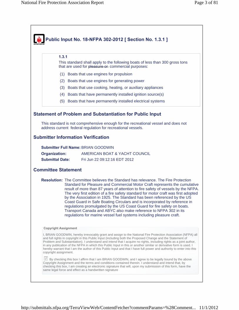
Public Input No. 18-NFPA 302-2012 [ Section No. 1.3.1 ]
1.3.1 This standard shall apply to the following boats of less than 300 gross tons that are used for pleasure or commercial purposes:
(1) Boats that use engines for propulsion
(2) Boats that use engines for generating power
(3) Boats that use cooking, heating, or auxiliary appliances
(4) Boats that have permanently installed ignition source(s)
(5) Boats that have permanently installed electrical systems
Statement of Problem and Substantiation for Public Input
This standard is not comprehensive enough for the recreational vessel and does not address current federal regulation for recreational vessels.
Submitter Information Verification
Submitter Full Name: BRIAN GOODWIN
Organization: AMERICAN BOAT & YACHT COUNCIL
Submittal Date: Fri Jun 22 09:12:16 EDT 2012
Committee Statement
Resolution: The Committee believes the Standard has relevance. The Fire Protection Standard for Pleasure and Commercial Motor Craft represents the cumulative result of more than 87 years of attention to fire safety of vessels by the NFPA. The very first edition of a fire safety standard for motor craft was first adopted by the Association in 1925. The Standard has been referenced by the US Coast Guard in Safe Boating Circulars and is incorporated by reference inregulations promulgated by the US Coast Guard for fire safety on boats.Transport Canada and ABYC also make reference to NFPA 302 in itsregulations for marine vessel fuel systems including pleasure craft.
Copyright Assignment
I, BRIAN GOODWIN, hereby irrevocably grant and assign to the National Fire Protection Association (NFPA) all and full rights in copyright in this Public Input (including both the Proposed Change and the Statement of Problem and Substantiation). I understand and intend that I acquire no rights, including rights as a joint author, in any publication of the NFPA in which this Public Input in this or another similar or derivative form is used. I hereby warrant that I am the author of this Public Input and that I have full power and authority to enter into this copyright assignment.
By checking this box I affirm that I am BRIAN GOODWIN, and I agree to be legally bound by the above Copyright Assignment and the terms and conditions contained therein. I understand and intend that, by checking this box, I am creating an electronic signature that will, upon my submission of this form, have the same legal force and effect as a handwritten signature
Page 3 of 81National Fire Protection Association Report
11/1/2012http://submittals.nfpa.org/TerraViewWeb/ContentFetcher?commentParams=%28Comment...

Public Input No. 17-NFPA 302-2012 [ Section No. 2.3.4 ]
2.3.4 ASTM Publications. ASTM International, 100 Barr Harbor Drive, P.O. Box C700, West Conshohocken, PA 19428-2959.
ASTM A 463 A463 /A 463M, Standard Specification for Steel Sheet, Aluminum-Coated, by the Hot-Dip Process, 2006 edition 2010 .
ASTM A 653 A653 /A 653M, Standard Specification for Steel Sheet, Zinc-Coated (Galvanized) or Zinc-Iron Alloy-Coated (Galvannealed) by the Hot-DipProcess, 2007 2011 .
ASTM B 97 B97 , Specification for Copper-Silicon Alloy Plate, Sheet, Strip, and Rolled Bar for General Purposes, 1981 edition (withdrawn) .
ASTM B 122 B122 /B 122 M, Standard Specification for Copper-Nickel-Tin Alloy, Copper-Nickel-Zinc Alloy (Nickel Silver), and Copper-Nickel Alloy Plate, Sheet, Strip, and Rolled Bar, 2006 edition 2011 .
ASTM B 127 B127 , Standard Specification for Nickel-Copper Alloy (UNS N05500) Plate, Sheet, and Strip, 2005 edition (2009) .
ASTM B 152 B152 /B 152 M, Standard Specification for Copper Sheet, Strip, Plate, and Rolled Bar, 2006 edition 2009 .
ASTM D 471 D471 , Standard Test Method for Rubber Property-Effect of Liquids, 2006 edition 2012 .
ASTM E84, Standard Test Method for Surface Burning Characteristics of Building Materials, 2012.
Statement of Problem and Substantiation for Public Input
Standards date updates
ASTM E84 has been proposed in public input.
Related Public Inputs for This Document
Related Input RelationshipPublic Input No. 12-NFPA 302-2012 [Section No. 8.2.1]
Public Input No. 10-NFPA 302-2012 [Section No. 4.1.6.1]
Submitter Information Verification
Submitter Full Name: Marcelo Hirschler
Organization: GBH International
Submittal Date: Tue Jun 19 13:03:55 EDT 2012
Committee Statement
Page 4 of 81National Fire Protection Association Report
11/1/2012http://submittals.nfpa.org/TerraViewWeb/ContentFetcher?commentParams=%28Comment...

Resolution: FR-12-NFPA 302-2012 The Committee changed the reference to ASTM B 97 since this publication has been withdrawn and replaced with ASTM B96/B96M, Standard Specification for Copper-Silicon Alloy Plate, Sheet, Strip, and Rolled Bar for General Purposes and Pressure Vessels, 2011 edition.
Statement: Standards date updates ASTM E84 has been proposed in public input.
Copyright Assignment
I, Marcelo Hirschler, hereby irrevocably grant and assign to the National Fire Protection Association (NFPA) all and full rights in copyright in this Public Input (including both the Proposed Change and the Statement of Problem and Substantiation). I understand and intend that I acquire no rights, including rights as a joint author, in any publication of the NFPA in which this Public Input in this or another similar or derivative form is used. Ihereby warrant that I am the author of this Public Input and that I have full power and authority to enter into this copyright assignment.
By checking this box I affirm that I am Marcelo Hirschler, and I agree to be legally bound by the above Copyright Assignment and the terms and conditions contained therein. I understand and intend that, by checking this box, I am creating an electronic signature that will, upon my submission of this form, have the same legal force and effect as a handwritten signature
Page 5 of 81National Fire Protection Association Report
11/1/2012http://submittals.nfpa.org/TerraViewWeb/ContentFetcher?commentParams=%28Comment...
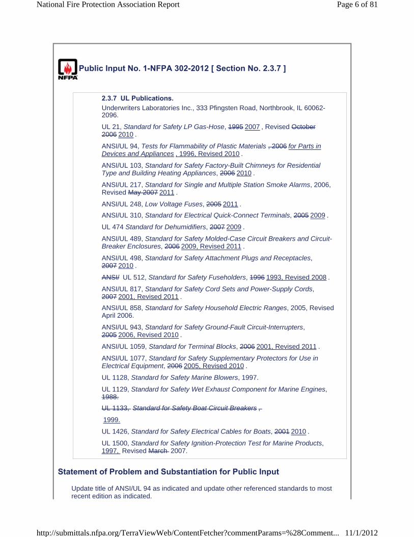
Public Input No. 1-NFPA 302-2012 [ Section No. 2.3.7 ]
2.3.7 UL Publications. Underwriters Laboratories Inc., 333 Pfingsten Road, Northbrook, IL 60062-2096.
UL 21, Standard for Safety LP Gas-Hose, 1995 2007 , Revised October 2006 2010 .
ANSI/UL 94, Tests for Flammability of Plastic Materials , 2006 for Parts in Devices and Appliances , 1996, Revised 2010 .
ANSI/UL 103, Standard for Safety Factory-Built Chimneys for Residential Type and Building Heating Appliances, 2006 2010 .
ANSI/UL 217, Standard for Single and Multiple Station Smoke Alarms, 2006, Revised May 2007 2011 .
ANSI/UL 248, Low Voltage Fuses, 2005 2011 .
ANSI/UL 310, Standard for Electrical Quick-Connect Terminals, 2005 2009 .
UL 474 Standard for Dehumidifiers, 2007 2009 .
ANSI/UL 489, Standard for Safety Molded-Case Circuit Breakers and Circuit-Breaker Enclosures, 2006 2009, Revised 2011 .
ANSI/UL 498, Standard for Safety Attachment Plugs and Receptacles,2007 2010 .
ANSI/ UL 512, Standard for Safety Fuseholders, 1996 1993, Revised 2008 .
ANSI/UL 817, Standard for Safety Cord Sets and Power-Supply Cords, 2007 2001, Revised 2011 .
ANSI/UL 858, Standard for Safety Household Electric Ranges, 2005, Revised April 2006.
ANSI/UL 943, Standard for Safety Ground-Fault Circuit-Interrupters,2005 2006, Revised 2010 .
ANSI/UL 1059, Standard for Terminal Blocks, 2006 2001, Revised 2011 .
ANSI/UL 1077, Standard for Safety Supplementary Protectors for Use inElectrical Equipment, 2006 2005, Revised 2010 .
UL 1128, Standard for Safety Marine Blowers, 1997.
UL 1129, Standard for Safety Wet Exhaust Component for Marine Engines, 1988.
UL 1133, Standard for Safety Boat Circuit Breakers ,
1999.
UL 1426, Standard for Safety Electrical Cables for Boats, 2001 2010 .
UL 1500, Standard for Safety Ignition-Protection Test for Marine Products, 1997, Revised March 2007.
Statement of Problem and Substantiation for Public Input
Update title of ANSI/UL 94 as indicated and update other referenced standards to most recent edition as indicated.
Page 6 of 81National Fire Protection Association Report
11/1/2012http://submittals.nfpa.org/TerraViewWeb/ContentFetcher?commentParams=%28Comment...

Submitter Information Verification
Submitter Full Name: John Bender
Organization: Underwriters Laboratories Inc.
Submittal Date: Thu Apr 19 09:27:47 EDT 2012
Committee Statement
Resolution: FR-2-NFPA 302-2012 The Committee found additional information about publication titles and revision dates that were verified by the submitter. Accordingly the Committee added ANSI approval designation to ANSI/UL 21, ANSI/UL 474 and ANSI/UL 1426 since these UL standards are now ANSI approved; updated titles and referenced edition of other referenced standards to the latest editions, and updated the format to be consistent with other standards listed in this section. ANSI/UL 512 has been renumbered as ANSI/UL 4248. UL 1133 was deleted since it can not be found on the ULwebsite.
Statement: Update title of ANSI/UL 94 as indicated and update other referenced standards to most recent edition as indicated.
Copyright Assignment
I, John Bender, hereby irrevocably grant and assign to the National Fire Protection Association (NFPA) all and full rights in copyright in this Public Input (including both the Proposed Change and the Statement of Problem and Substantiation). I understand and intend that I acquire no rights, including rights as a joint author, in any publication of the NFPA in which this Public Input in this or another similar or derivative form is used. I hereby warrant that I am the author of this Public Input and that I have full power and authority to enter into this copyright assignment.
By checking this box I affirm that I am John Bender, and I agree to be legally bound by the above Copyright Assignment and the terms and conditions contained therein. I understand and intend that, by checking this box, I am creating an electronic signature that will, upon my submission of this form, have the same legal force and effect as a handwritten signature
Page 7 of 81National Fire Protection Association Report
11/1/2012http://submittals.nfpa.org/TerraViewWeb/ContentFetcher?commentParams=%28Comment...

Public Input No. 13-NFPA 302-2012 [ Section No. 3.3.19 ]
3.3.19 Ground-Fault Circuit-Interrupter (GFCI). A device intended for the protection of personnel that functions to de-energize a circuit or portion thereof within an established period of time when a fault current to ground exceeds the values established for a Class A device. somepredetermined value that is less than that required to operate the overcurrentprotective device of the supply circuit. This device will not provide personnelprotection from electrocution resulting from line-to-line contact since thenature of line-to-line loads cannot be distinguished.
FPN: Class A ground-fault circuit interrupters trip when the current to ground is 6 mA or higher and do not trip when the current to ground is less than 4 mA. For further information, see UL 943, Standard for Ground-Fault Circuit Interrupters. [70: 100.1]
Statement of Problem and Substantiation for Public Input
This proposal is intended to generate consistent definitions and minimize the number of duplicate definitions in the NFPA Glossary of Terms.The addition of the last sentence is safety information to the user of the Standard.The proposed wording should meet the intent of 3 preferred and 2 secondary definitions
used in 8 NFPA Standards.Similar proposals are being submitted to NFPA 70, 70B, 70E, 73, 99, 99B, and 1901.
Submitter Information Verification
Submitter Full Name: JAMES DALY
Organization: Submittal Date: Wed Jun 06 07:05:09 EDT 2012
Committee Statement
Resolution: NFPA 302 is a fire protection standard and the definition in the standard is sufficient for the purpose and scope of the document.
Copyright Assignment
I, JAMES DALY, hereby irrevocably grant and assign to the National Fire Protection Association (NFPA) all and full rights in copyright in this Public Input (including both the Proposed Change and the Statement of Problem and Substantiation). I understand and intend that I acquire no rights, including rights as a joint author, in any publication of the NFPA in which this Public Input in this or another similar or derivative form is used. I herebywarrant that I am the author of this Public Input and that I have full power and authority to enter into this copyright assignment.
By checking this box I affirm that I am JAMES DALY, and I agree to be legally bound by the above Copyright Assignment and the terms and conditions contained therein. I understand and intend that, by checking this box, I am creating an electronic signature that will, upon my submission of this form, have the same legal force and effect as a handwritten signature
Page 8 of 81National Fire Protection Association Report
11/1/2012http://submittals.nfpa.org/TerraViewWeb/ContentFetcher?commentParams=%28Comment...
Public Input No. 16-NFPA 302-2012 [ Section No. 3.3.45 ]
3.3.45* Ventilation. The changing of air within a compartment by natural or mechanical poweredmeans.
Statement of Problem and Substantiation for Public Input
consistency with other marine industry stadards
Submitter Information Verification
Submitter Full Name: Robert Newsome
Organization: NMMA
Submittal Date: Tue Jun 19 10:40:07 EDT 2012
Committee Statement
Resolution: FR-3-NFPA 302-2012
Statement: This change creates consistency with other marine industry standards.
Copyright Assignment
I, Robert Newsome, hereby irrevocably grant and assign to the National Fire Protection Association (NFPA) all and full rights in copyright in this Public Input (including both the Proposed Change and the Statement ofProblem and Substantiation). I understand and intend that I acquire no rights, including rights as a joint author, in any publication of the NFPA in which this Public Input in this or another similar or derivative form is used. I hereby warrant that I am the author of this Public Input and that I have full power and authority to enter into this copyright assignment.
By checking this box I affirm that I am Robert Newsome, and I agree to be legally bound by the above Copyright Assignment and the terms and conditions contained therein. I understand and intend that, by checking this box, I am creating an electronic signature that will, upon my submission of this form, have the same legal force and effect as a handwritten signature
Page 9 of 81National Fire Protection Association Report
11/1/2012http://submittals.nfpa.org/TerraViewWeb/ContentFetcher?commentParams=%28Comment...
Public Input No. 10-NFPA 302-2012 [ Section No. 4.1.6.1 ]
4.1.6.1 Materials used for thermal and acoustical insulation in any compartment or enclosure containing an internal combustion engine or heater shall have a flame spread index of 75 or less, when tested in accordance with ASTM E 84, Standard Test Method for Surface Burning Characteristics of Building Materials .
Statement of Problem and Substantiation for Public Input
It is important to state the test method to be used for assessing the flame spread index. This does not introduce a change in requirements.
NFPA 302 refers (in another section) to NFPA 255, which has now been withdrawn. ASTM E84, Standard Test Method for Surface Burning Characteristics of Building Materials, is technically equivalent to what used to be NFPA 255 and is the up-to-date test method.
The change will also require the addition of ASTM E84, Standard Test Method for Surface Burning Characteristics of Building Materials, to section to on referenced ASTM standards. The latest edition, and the one that should be referenced, is 2012.
Submitter Information Verification
Submitter Full Name: Marcelo Hirschler
Organization: GBH International
Submittal Date: Thu May 31 21:51:06 EDT 2012
Committee Statement
Resolution: FR-5-NFPA 302-2012
Statement: It is important to state the test method to be used for assessing the flame spread index. This does not introduce a change in requirements. NFPA 302 refers (in another section) to NFPA 255, which has now been withdrawn. ASTM E84, Standard Test Method for Surface Burning Characteristics of Building Materials, is technically equivalent to what used to be NFPA 255 and is the up-to-date test method. The change will also require the addition of ASTM E84, Standard Test Method for Surface Burning Characteristics of Building Materials, to section to on referenced ASTM standards. The latest edition, and the one that should be referenced, is 2012.
Copyright Assignment
I, Marcelo Hirschler, hereby irrevocably grant and assign to the National Fire Protection Association (NFPA) all and full rights in copyright in this Public Input (including both the Proposed Change and the Statement of Problem and Substantiation). I understand and intend that I acquire no rights, including rights as a joint author, in any publication of the NFPA in which this Public Input in this or another similar or derivative form is used. Ihereby warrant that I am the author of this Public Input and that I have full power and authority to enter into this copyright assignment.
Page 10 of 81National Fire Protection Association Report
11/1/2012http://submittals.nfpa.org/TerraViewWeb/ContentFetcher?commentParams=%28Comment...

By checking this box I affirm that I am Marcelo Hirschler, and I agree to be legally bound by the above Copyright Assignment and the terms and conditions contained therein. I understand and intend that, by checking this box, I am creating an electronic signature that will, upon my submission of this form, have the same legal force and effect as a handwritten signature
Page 11 of 81National Fire Protection Association Report
11/1/2012http://submittals.nfpa.org/TerraViewWeb/ContentFetcher?commentParams=%28Comment...

Public Input No. 6-NFPA 302-2012 [ Section No. 4.5.1 ]
4.5.1 Each compartment not open to the atmosphere that has a permanently installed gasoline engine installed internal combustion engine with a cranking motor and a fixed fire extinguishing system shall be ventilated by an exhaustblower.
Statement of Problem and Substantiation for Public Input
The purpose of an exhaust blower is not only to remove accumulated gasoline vapors from an engine compartment but also to remove any byproducts of combustion or remaining extinguishing agent after the discharge of a fixed fire extinguishing system. (The committee may also want to require a blower if a portable gaseous extingusiher and fire port are used in lieu of a fixed system.)
Submitter Information Verification
Submitter Full Name: Kim MacCartney
Organization: Ace Recreational Marine Insura
Submittal Date: Thu May 17 07:57:07 EDT 2012
Committee Statement
Resolution: The Committee took the material from this public input and created a separate First Revision (FR-7) that created a new section 4.5.1.1.
Copyright Assignment
I, Kim MacCartney, hereby irrevocably grant and assign to the National Fire Protection Association (NFPA) all and full rights in copyright in this Public Input (including both the Proposed Change and the Statement ofProblem and Substantiation). I understand and intend that I acquire no rights, including rights as a joint author, in any publication of the NFPA in which this Public Input in this or another similar or derivative form is used. I hereby warrant that I am the author of this Public Input and that I have full power and authority to enter into this copyright assignment.
By checking this box I affirm that I am Kim MacCartney, and I agree to be legally bound by the above Copyright Assignment and the terms and conditions contained therein. I understand and intend that, by checking this box, I am creating an electronic signature that will, upon my submission of this form, have the same legal force and effect as a handwritten signature
Page 12 of 81National Fire Protection Association Report
11/1/2012http://submittals.nfpa.org/TerraViewWeb/ContentFetcher?commentParams=%28Comment...
Public Input No. 11-NFPA 302-2012 [ Section No. 5.5.3.2.1 ]
5.5.3.2.1 Ducts for engine-cooling air shall have exhibit a flame spread index of 75 or less when tested in accordance with ASTM E 84, Standard Test Method for Surface Burning Characteristics of Building Materials .
Statement of Problem and Substantiation for Public Input
It is important to state the test method to be used for assessing the flame spread index. This does not introduce a change in requirements.
NFPA 302 refers (in another section) to NFPA 255, which has now been withdrawn. ASTM E84, Standard Test Method for Surface Burning Characteristics of Building Materials, is technically equivalent to what used to be NFPA 255 and is the up-to-date test method.
The change will also require the addition of ASTM E84, Standard Test Method for Surface Burning Characteristics of Building Materials, to section to on referenced ASTM standards. The latest edition, and the one that should be referenced, is 2012.
Related Public Inputs for This Document
Related Input RelationshipPublic Input No. 12-NFPA 302-2012 [Section No. 8.2.1]
Public Input No. 17-NFPA 302-2012 [Section No. 2.3.4]
Submitter Information Verification
Submitter Full Name: Marcelo Hirschler
Organization: GBH International
Submittal Date: Thu May 31 21:58:38 EDT 2012
Committee Statement
Resolution: FR-10-NFPA 302-2012
Statement: It is important to state the test method to be used for assessing the flame spread index. This does not introduce a change in requirements. NFPA 302 refers (in another section) to NFPA 255, which has now been withdrawn. ASTM E84, Standard Test Method for Surface Burning Characteristics of Building Materials, is technically equivalent to what used to be NFPA 255 and is the up-to-date test method. The change will also require the addition of ASTM E84, Standard Test Method for Surface Burning Characteristics of Building Materials, to section to on referenced ASTM standards. The latest edition, and the one that should be referenced, is 2012.
Copyright Assignment
Page 13 of 81National Fire Protection Association Report
11/1/2012http://submittals.nfpa.org/TerraViewWeb/ContentFetcher?commentParams=%28Comment...

I, Marcelo Hirschler, hereby irrevocably grant and assign to the National Fire Protection Association (NFPA) all and full rights in copyright in this Public Input (including both the Proposed Change and the Statement of Problem and Substantiation). I understand and intend that I acquire no rights, including rights as a joint author, in any publication of the NFPA in which this Public Input in this or another similar or derivative form is used. Ihereby warrant that I am the author of this Public Input and that I have full power and authority to enter into this copyright assignment.
By checking this box I affirm that I am Marcelo Hirschler, and I agree to be legally bound by the above Copyright Assignment and the terms and conditions contained therein. I understand and intend that, by checking this box, I am creating an electronic signature that will, upon my submission of this form, have the same legal force and effect as a handwritten signature
Page 14 of 81National Fire Protection Association Report
11/1/2012http://submittals.nfpa.org/TerraViewWeb/ContentFetcher?commentParams=%28Comment...

Public Input No. 21-NFPA 302-2012 [ Sections 6.1, 6.2, 6.3, 6.4 ]
Sections 6.1, 6.2, 6.3, 6.46.1 General Requirements. 6.1.1 Exhaust systems shall comply with the following:
(1) They shall be gastight to hull interiors.
(2) All connections shall be accessible.
(3) They shall be supported to minimize failure from vibration, shock, expansion, and contraction.
(4) They shall have no threaded fittings into nonmetallic exhaust system components.
(5) They shall have no discharge from other devices into the exhaust other than from engine-cooling water.
6.1.2 Wherever personnel or combustibles can come in contact with hot surfaces, effective protection shall be provided by water-jacketing, lagging, or shielding, or by guards or engine enclosures.6.1.3 Exhaust Supports. 6.1.3.1 For wet exhaust systems, hangers, brackets, or other means used to support metallic exhaust systems shall be noncombustible within 6 ft (1.8 m) of the engine connection(s).6.1.3.2 For dry exhaust systems, hangers, brackets, or other means used to support metallic exhaust systems shall be noncombustible.6.1.4 Except for outboard engines, a means to indicate loss of exhaust-cooling water shall be provided so that it is effective at all helm positions.6.1.5 Non-propulsion engines shall be permitted to use an automatic shutdown device to meet the requirements of 6.1.4 .6.1.6 A separate exhaust system shall be provided for each engine.6.2 Materials. 6.2.1 Materials used in engine exhaust systems, except in components addressed in 6.2.3 and 6.2.4 , shall be resistant to fuels, heat, water, corrosion, and the products of combustion.6.2.2 Nonmetallic exhaust system components, except for those components addressed in 6.2.3 and 6.2.4 , shall meet the requirements of UL 1129, Standard for Safety Wet Exhaust Components for Marine Engines , or SAE J2006, Standard on Marine Exhaust Hose , and shall be so marked.
Page 15 of 81National Fire Protection Association Report
11/1/2012http://submittals.nfpa.org/TerraViewWeb/ContentFetcher?commentParams=%28Comment...
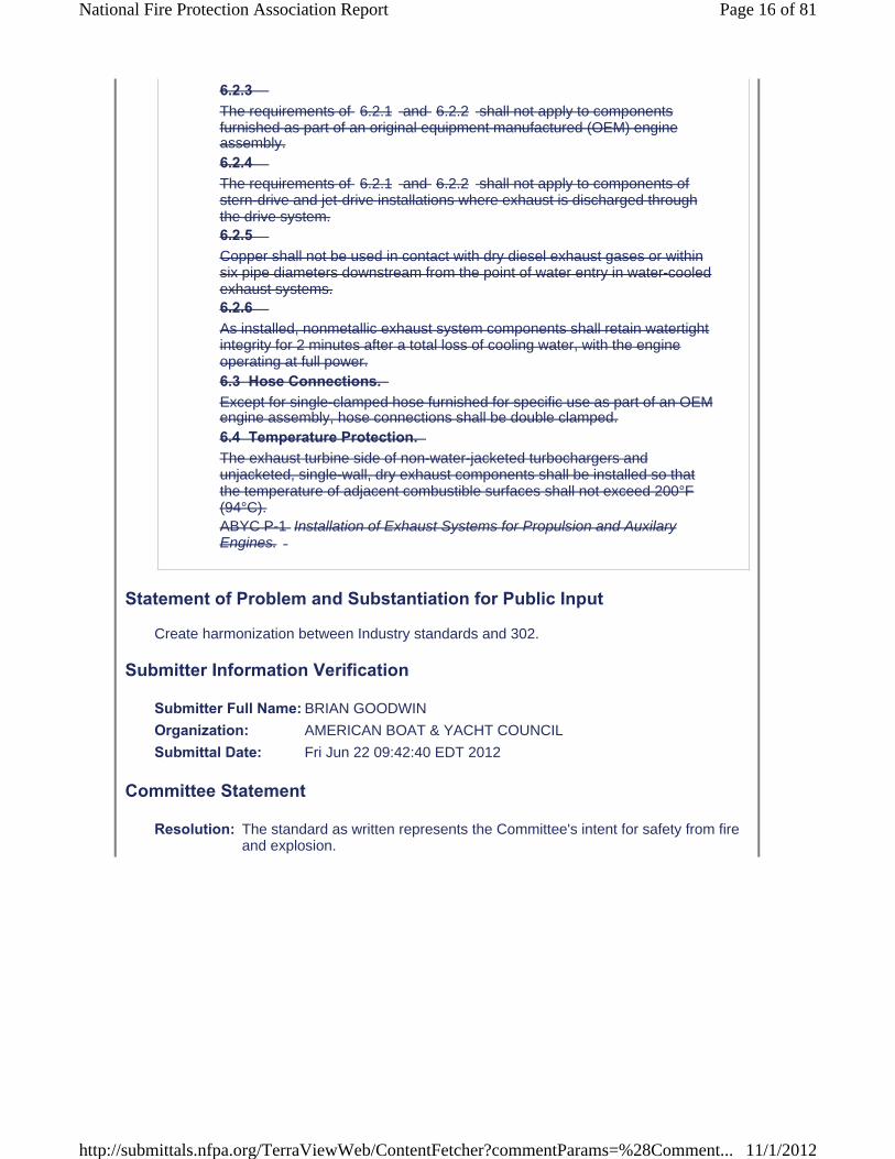
6.2.3 The requirements of 6.2.1 and 6.2.2 shall not apply to components furnished as part of an original equipment manufactured (OEM) engine assembly.6.2.4 The requirements of 6.2.1 and 6.2.2 shall not apply to components of stern-drive and jet-drive installations where exhaust is discharged through the drive system.6.2.5 Copper shall not be used in contact with dry diesel exhaust gases or within six pipe diameters downstream from the point of water entry in water-cooled exhaust systems.6.2.6 As installed, nonmetallic exhaust system components shall retain watertight integrity for 2 minutes after a total loss of cooling water, with the engine operating at full power.6.3 Hose Connections. Except for single-clamped hose furnished for specific use as part of an OEM engine assembly, hose connections shall be double clamped.6.4 Temperature Protection. The exhaust turbine side of non-water-jacketed turbochargers and unjacketed, single-wall, dry exhaust components shall be installed so that the temperature of adjacent combustible surfaces shall not exceed 200°F (94°C).ABYC P-1 Installation of Exhaust Systems for Propulsion and Auxilary Engines.
Statement of Problem and Substantiation for Public Input
Create harmonization between Industry standards and 302.
Submitter Information Verification
Submitter Full Name: BRIAN GOODWIN
Organization: AMERICAN BOAT & YACHT COUNCIL
Submittal Date: Fri Jun 22 09:42:40 EDT 2012
Committee Statement
Resolution: The standard as written represents the Committee's intent for safety from fire and explosion.
Page 16 of 81National Fire Protection Association Report
11/1/2012http://submittals.nfpa.org/TerraViewWeb/ContentFetcher?commentParams=%28Comment...
Copyright Assignment
I, BRIAN GOODWIN, hereby irrevocably grant and assign to the National Fire Protection Association (NFPA) all and full rights in copyright in this Public Input (including both the Proposed Change and the Statement of Problem and Substantiation). I understand and intend that I acquire no rights, including rights as a joint author, in any publication of the NFPA in which this Public Input in this or another similar or derivative form is used. I hereby warrant that I am the author of this Public Input and that I have full power and authority to enter into this copyright assignment.
By checking this box I affirm that I am BRIAN GOODWIN, and I agree to be legally bound by the above Copyright Assignment and the terms and conditions contained therein. I understand and intend that, by checking this box, I am creating an electronic signature that will, upon my submission of this form, have the same legal force and effect as a handwritten signature
Page 17 of 81National Fire Protection Association Report
11/1/2012http://submittals.nfpa.org/TerraViewWeb/ContentFetcher?commentParams=%28Comment...

Public Input No. 7-NFPA 302-2012 [ Section No. 6.1.1 ]
6.1.1 Exhaust systems shall comply with the following:
(1) They shall be gastight to hull interiors.
(2) All connections shall be accessible.
(3) They shall be supported to minimize failure from vibration, shock, expansion, and contraction.
(4) They shall have no threaded fittings into nonmetallic exhaust system components.
(5) They shall have no discharge from other devices into the exhaust other than from engine-cooling water.
(6) Exhaust systems on gasoline fueled internal combustion engines shall be designed and installed to reduce the production of carbon monoxide by providing the minimum restriction to exhaust gas flow practicable.
Statement of Problem and Substantiation for Public Input
Bob Loeser did extensive testing on this subject and found that by reducing the number of elbows and other restriction to exhaust gas flow the level of CO production could be reduced by several magnitudes. This reduction also lead to increased fuel economy.
Submitter Information Verification
Submitter Full Name: Kim MacCartney
Organization: Ace Recreational Marine Insura
Submittal Date: Thu May 17 08:17:13 EDT 2012
Committee Statement
Resolution: FR-19-NFPA 302-2012 Public Input no. 7-NFPA 302-2012 [Section No. 6.1.1] is established as a separate requirement under Section 6.1.1 in accordancewith the Manual of Style for NFPA Technical Committee Documents, July2004. The Committee struck, "fueled internal combustion ", from theproposed requirement for editorial purposes.
Statement: Bob Loeser did extensive testing on this subject and found that by reducing the number of elbows and other restriction to exhaust gas flow the level of CO production could be reduced by several magnitudes. This reduction also lead to increased fuel economy.
Copyright Assignment
I, Kim MacCartney, hereby irrevocably grant and assign to the National Fire Protection Association (NFPA) all and full rights in copyright in this Public Input (including both the Proposed Change and the Statement of Problem and Substantiation). I understand and intend that I acquire no rights, including rights as a joint author, in any publication of the NFPA in which this Public Input in this or another similar or derivative form is used. I hereby warrant that I am the author of this Public Input and that I have full power and authority to enter into this copyright assignment.
Page 18 of 81National Fire Protection Association Report
11/1/2012http://submittals.nfpa.org/TerraViewWeb/ContentFetcher?commentParams=%28Comment...

By checking this box I affirm that I am Kim MacCartney, and I agree to be legally bound by the above Copyright Assignment and the terms and conditions contained therein. I understand and intend that, by checking this box, I am creating an electronic signature that will, upon my submission of this form, have the same legal force and effect as a handwritten signature
Page 19 of 81National Fire Protection Association Report
11/1/2012http://submittals.nfpa.org/TerraViewWeb/ContentFetcher?commentParams=%28Comment...

Public Input No. 22-NFPA 302-2012 [ Sections 7.1, 7.2, 7.3, 7.4, 7.5 ]
Sections 7.1, 7.2, 7.3, 7.4, 7.57.1 General Requirements. 7.1.
1 Scope. 7.1.1.1 The requirements of this chapter shall apply to the design, construction, choice of materials, and installation of permanently installed fuel systems, except compressed gas, that run from the fuel fill opening to the connections at each engine or at auxiliary equipment.7.1.1.2 The requirements of this chapter shall apply to all tanks that are permanently installed.7.1.2 Any tanks with a capacity of more than 7 gal (27 L) shall be permanently installed.7.1.3 Fuel systems shall be liquidtight and vaportight with respect to hull interiors.7.1.4 Individual system components and the system as a whole shall be designed and installed to withstand the stresses of and exposure to marine service including pressure, vibration, shock, movement, grease, lubricating oil, bilge solvents, high aromatic fuels, and corrosive environments.7.1.5 Exposure Fire Protection. 7.1.5.1 As installed in the boat, all individual components of the fuel system, except for the components identified in 7.1.5.2 and 7.1.5.3 , shall be capable of
withstanding a 2 1 ? 2 -minute exposure to free-burning fuel without a failure that results in leakage of liquid or vapor.7.1.5.2 Fuel distribution lines on boats shall not be required to comply with 7.1.5.1 if a break at any point in the line will cause a discharge of not more than 5.0 fl
oz (150 ml) of fuel within 2 1 ? 2 minutes. (See 7.5.1.5 .)7.1.5.3 Self-draining fuel tank vent hose located outside the engine compartment shall not be required to comply with 7.1.5.1 .7.1.6 To ground static electricity, the resistance between ground and each metallic or metallic-plated component of the fuel fill system and fuel tank that is in contact with fuel shall be less than 1 ohm.7.1.7 Pressurized fuel tanks shall not be used.7.2 Fuel Tank Materials. 7.2.1 Hull Integration. 7.2.1.1 Gasoline Tanks. Gasoline fuel tanks shall not be integral with the hull structure.7.2.1.2 Diesel Tanks.
Page 20 of 81National Fire Protection Association Report
11/1/2012http://submittals.nfpa.org/TerraViewWeb/ContentFetcher?commentParams=%28Comment...

7.2.1.2.1 Diesel tanks shall be permitted to be integral with the hull structure.7.2.1.2.2 If cored composite construction is used where the tank is integral with the hull structure, the core material shall not deteriorate due to contact with diesel fuel and shall not permit diesel fuel to migrate.7.2.2 Corrosion Resistance. 7.2.2.1 Materials for fuel tanks shall be corrosion resistant.7.2.2.2
Materials shall meet the specifications of Table 7.2.2.2 .
Table 7.2.2.2 Metallic Fuel Tank Material and Fabrication Requirements for Corrosion Resistance
Material a Specification Minimum Nominal Sheet Thickness Gauge Nickel-copper ASTM B 127, Class A 0.031 in. (0.79 mm) 22 U.S. Std. Copper-nickel ASTM B 122 0.045 in. (1.14 mm) 17 AWG Copper ASTM B 152, Type E.T.P. 0.057 in. (1.45 mm) 15 AWG Copper-silicon ASTM B 97, Types A, B, and G 0.050 in. (1.27 mm) 16 AWG Steel sheet ASTM A 653/A 653M 0.0747 in. (1.90 mm) 14 Mfrs. Aluminizedsteel ASTM A 463 0.0478 in. (1.21 mm) 18 Mfrs. Aluminum Alloy 5052, 5083, or5086 0.090 in. (2.29 mm) — Stainless steel 316L or 317L 0.0747 in. (1.90 mm) 0.031 in. (0.79 mm) b 14 Mfrs.
22 U.S. Std. b
a See American Welding Society recommendations for welding processes.
b Only cylindrical stainless steel tanks with domed heads and a capacity of less than20 gal (76 L) are permitted.
7.2.2.3 The following shall apply to steel tanks used for fuel:
(1) Unless constructed of aluminized steel, they shall be galvanized inside and outside by the hot-dip process for other than diesel fuel tanks.
(2) Unless constructed of aluminized steel, they shall be galvanized on the outside only by the hot-dip process for diesel fuel tanks.
(3) They shall not be constructed of terneplate steel.
7.2.2.4 Aluminized steel tanks with a wall thickness of less than 0.0785 in. (2 mm) shall be installed only above the cockpit floor or above the deck if no clearly defined cockpit exists.7.2.2.5 Stainless Steel Diesel Fuel Tanks. 7.2.2.5.1 Stainless steel diesel fuel tanks, except those identified in 7.2.2.5.2 , shallhave a wall thickness of not less than 0.0747 in. (14 gauge).7.2.2.5.2 Stainless steel fuel tanks that are both less than 20 gal (76 L) capacity and of cylindrical construction with domed heads shall require a wall thickness of not less than 0.031 in. (22 gauge).7.2.2.5.3 *
Page 21 of 81National Fire Protection Association Report
11/1/2012http://submittals.nfpa.org/TerraViewWeb/ContentFetcher?commentParams=%28Comment...
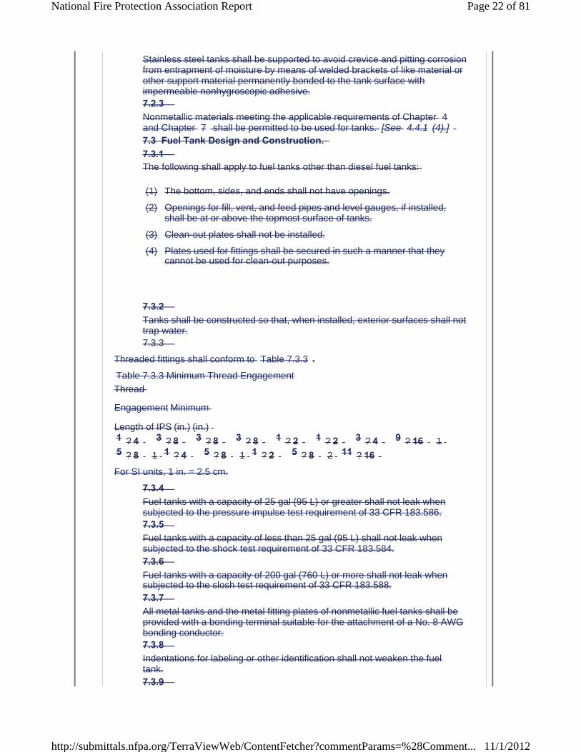
Stainless steel tanks shall be supported to avoid crevice and pitting corrosion from entrapment of moisture by means of welded brackets of like material or other support material permanently bonded to the tank surface with impermeable nonhygroscopic adhesive.7.2.3 Nonmetallic materials meeting the applicable requirements of Chapter 4and Chapter 7 shall be permitted to be used for tanks. [See 4.4.1 (4).]7.3 Fuel Tank Design and Construction. 7.3.1 The following shall apply to fuel tanks other than diesel fuel tanks:
(1) The bottom, sides, and ends shall not have openings.
(2) Openings for fill, vent, and feed pipes and level gauges, if installed, shall be at or above the topmost surface of tanks.
(3) Clean-out plates shall not be installed.
(4) Plates used for fittings shall be secured in such a manner that they cannot be used for clean-out purposes.
7.3.2 Tanks shall be constructed so that, when installed, exterior surfaces shall not trap water.7.3.3
Threaded fittings shall conform to Table 7.3.3 .
Table 7.3.3 Minimum Thread Engagement
Thread
Engagement Minimum
Length of IPS (in.) (in.)1 ? 4 3 ? 8 3 ? 8 3 ? 8 1 ? 2 1 ? 2 3 ? 4 9 ? 16 15 ? 8 1 1 ? 4 5 ? 8 1 1 ? 2 5 ? 8 2 11 ? 16For SI units, 1 in. = 2.5 cm.
7.3.4 Fuel tanks with a capacity of 25 gal (95 L) or greater shall not leak when subjected to the pressure impulse test requirement of 33 CFR 183.586.7.3.5 Fuel tanks with a capacity of less than 25 gal (95 L) shall not leak when subjected to the shock test requirement of 33 CFR 183.584.7.3.6 Fuel tanks with a capacity of 200 gal (760 L) or more shall not leak when subjected to the slosh test requirement of 33 CFR 183.588.7.3.7 All metal tanks and the metal fitting plates of nonmetallic fuel tanks shall be provided with a bonding terminal suitable for the attachment of a No. 8 AWG bonding conductor.7.3.8 Indentations for labeling or other identification shall not weaken the fuel tank.7.3.9
Page 22 of 81National Fire Protection Association Report
11/1/2012http://submittals.nfpa.org/TerraViewWeb/ContentFetcher?commentParams=%28Comment...

Fuel tanks shall be marked or identified permanently with the following information in a location that is visible and readable for inspection after installation:
(1) Manufacturer's name or logo and address
(2) Month (or lot or serial number) and year of manufacture
(3) Capacity in U.S. gallons (capacity also shall be permitted to be expressed in liters)
(4) Construction material and thickness
(5) Fuel for which tank is intended
(6) Maximum test pressure
(7) Model number, if applicable
(8) Statement on tanks other than diesel tanks that reads, “This tank has been tested under 33 CFR 183.510(a).”
(9) Statement that reads, “Must be installed aft of the half-length of the boat,” if the tank has been tested under 33 CFR 183.584, at less than 25 G vertical accelerations
7.3.10 Fuel tank(s) shall be tested by the manufacturer or builder for fuel tightness
at 3.0 psi (21 kPa gauge) or 1 1 ? 2 times the maximum static head to which the tank(s) can be subjected during service as specified by the boat manufacturer, whichever is greater.7.3.11 The design of the pickup tube shall preclude damage to the tank bottom as the tank flexes while in service.7.3.12 The use of gauge glasses shall be restricted to day tanks and service tanks of diesel fuel systems.7.4 Fuel Tank Installation. 7.4.1 Fuel tank connections and fittings shall be accessible.7.4.2 Fuel tanks, other than diesel fuel tanks integral with the hull, shall be installed in such a manner that means for maintenance or replacement is provided or indicated so that it can be accomplished without compromising the structural integrity of the vessel.7.4.3 Fuel tanks shall be installed in a manner that prevents permanentdeformation.7.4.4 Fuel tanks shall be installed in a manner that provides immobilization to the extent practicable.7.4.5 Nonmetallic fuel tanks that expand dimensionally after exposure to fuel shall comply with the following:
(1) They shall be installed in accordance with the fuel tank manufacturer's instructions
Page 23 of 81National Fire Protection Association Report
11/1/2012http://submittals.nfpa.org/TerraViewWeb/ContentFetcher?commentParams=%28Comment...

(2) The fuel tank manufacturer's instructions shall indicate the installationclearances required for the tank in diagram form.
(3) They shall be provided with a warning label that contains at a minimum the following informational elements:
CAUTION: To prevent hull and tank damage due to expansion of the tank while in service, installation shall be in accordance with themanufacturer's instructions.
7.4.6 Contact between metallic fuel tanks and other structures shall be limited to necessary structural supports and shall permit free circulation of air.7.4.7 Abrasive surfaces and absorbent surfaces of tank supports and braces shall be insulated effectively from contact with tank surfaces by a nonabrasive and nonabsorbent material.7.4.8 Aluminized steel tanks of thicknesses less than 0.0785 in. (2 mm) shall be installed above the cockpit deck or above deck if there is no clearly defined cockpit.7.4.9 Nonferrous and nonmetallic fuel tanks shall be permitted to be foamed in place if they comply with the requirements of 33 CFR 183.516. (See7.4.5 .)7.4.10 Fuel tanks shall not be installed above the engine and shall not be installed above sources of ignition.7.4.11 Fuel tank(s) shall not support a deck, a bulkhead, or other structure.7.5 Fuel Lines, Fittings, and Related Accessories. 7.5.1 General. 7.5.1.1 For the purposes of Section 7.5 , fuel lines shall mean all pipes, tubing, or hose that conduct fuel from the deck fill plate to the engine connection.7.5.1.2 For the purposes of Section 7.5 , related accessories shall include any attachments to fuel lines such as valves, filters, strainers, pumps, and connecting fittings.7.5.1.3 All fuel tank fittings shall be galvanically compatible with the fuel tank material.7.5.1.4 Copper-bearing fittings shall be isolated from aluminum tanks by a galvanic barrier including, but not limited to, a 300 series stainless steel fitting.7.5.1.5 Flexible nonmetallic fuel hose shall be one of the following:
(1) USCG Type A-1 or A-1-15 or Type A-2 hose where 2 1 ? 2 -minutes minimum fire resistance is required
Page 24 of 81National Fire Protection Association Report
11/1/2012http://submittals.nfpa.org/TerraViewWeb/ContentFetcher?commentParams=%28Comment...
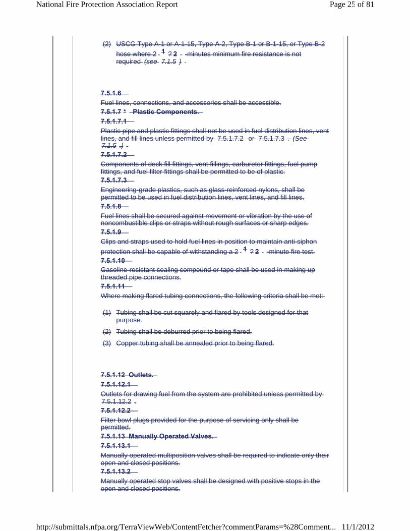
(2) USCG Type A-1 or A-1-15, Type A-2, Type B-1 or B-1-15, or Type B-2
hose where 2 1 ? 2 -minutes minimum fire resistance is not required (see 7.1.5 )
7.5.1.6 Fuel lines, connections, and accessories shall be accessible.7.5.1.7 * Plastic Components. 7.5.1.7.1 Plastic pipe and plastic fittings shall not be used in fuel distribution lines, vent lines, and fill lines unless permitted by 7.5.1.7.2 or 7.5.1.7.3 . (See 7.1.5 .)7.5.1.7.2 Components of deck fill fittings, vent fillings, carburetor fittings, fuel pump fittings, and fuel filter fittings shall be permitted to be of plastic.7.5.1.7.3 Engineering-grade plastics, such as glass-reinforced nylons, shall be permitted to be used in fuel distribution lines, vent lines, and fill lines.7.5.1.8 Fuel lines shall be secured against movement or vibration by the use of noncombustible clips or straps without rough surfaces or sharp edges.7.5.1.9 Clips and straps used to hold fuel lines in position to maintain anti-siphon
protection shall be capable of withstanding a 2 1 ? 2 -minute fire test.7.5.1.10 Gasoline-resistant sealing compound or tape shall be used in making up threaded pipe connections.7.5.1.11 Where making flared tubing connections, the following criteria shall be met:
(1) Tubing shall be cut squarely and flared by tools designed for that purpose.
(2) Tubing shall be deburred prior to being flared.
(3) Copper tubing shall be annealed prior to being flared.
7.5.1.12 Outlets. 7.5.1.12.1 Outlets for drawing fuel from the system are prohibited unless permitted by 7.5.1.12.2 .7.5.1.12.2 Filter bowl plugs provided for the purpose of servicing only shall be permitted.7.5.1.13 Manually Operated Valves. 7.5.1.13.1 Manually operated multiposition valves shall be required to indicate only their open and closed positions.7.5.1.13.2 Manually operated stop valves shall be designed with positive stops in the open and closed positions.
Page 25 of 81National Fire Protection Association Report
11/1/2012http://submittals.nfpa.org/TerraViewWeb/ContentFetcher?commentParams=%28Comment...
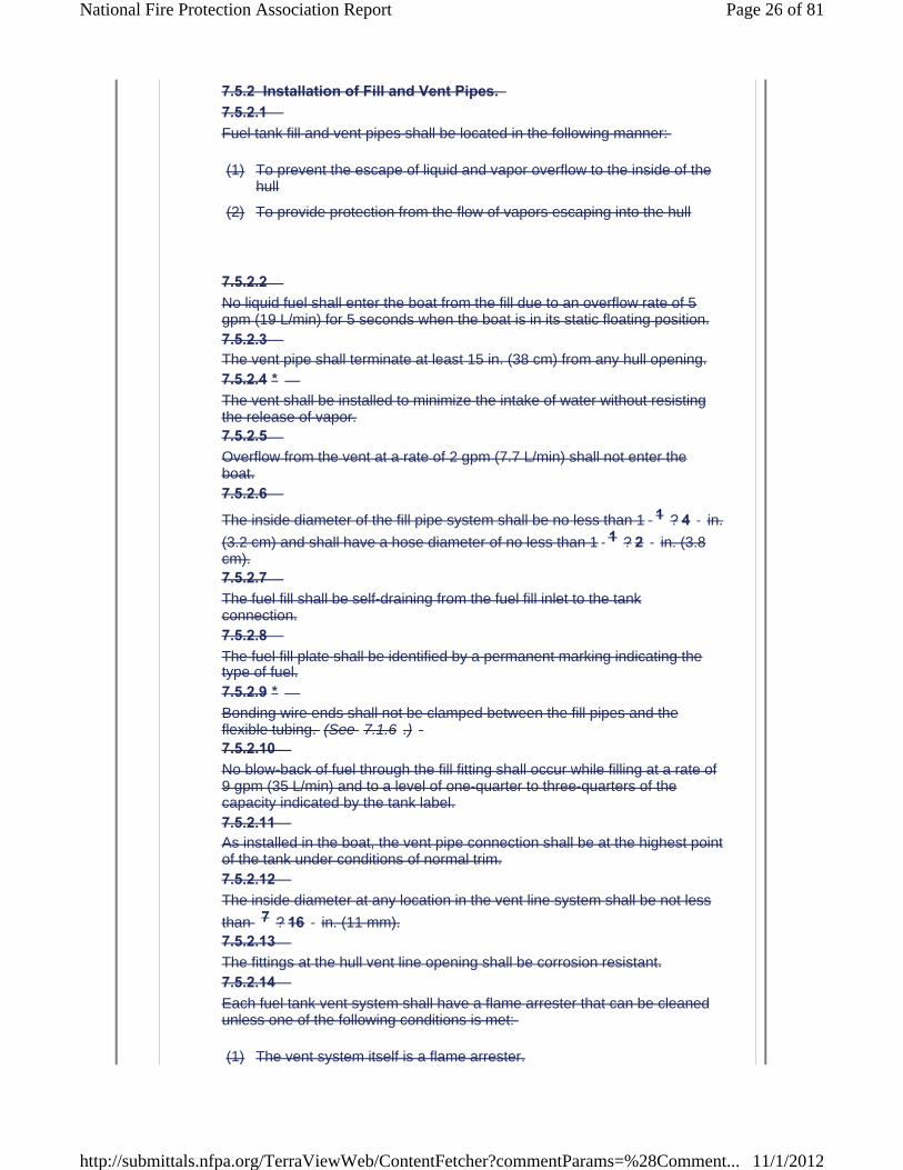
7.5.2 Installation of Fill and Vent Pipes. 7.5.2.1 Fuel tank fill and vent pipes shall be located in the following manner:
(1) To prevent the escape of liquid and vapor overflow to the inside of the hull
(2) To provide protection from the flow of vapors escaping into the hull
7.5.2.2 No liquid fuel shall enter the boat from the fill due to an overflow rate of 5 gpm (19 L/min) for 5 seconds when the boat is in its static floating position.7.5.2.3 The vent pipe shall terminate at least 15 in. (38 cm) from any hull opening.7.5.2.4 *The vent shall be installed to minimize the intake of water without resisting the release of vapor.7.5.2.5 Overflow from the vent at a rate of 2 gpm (7.7 L/min) shall not enter the boat.7.5.2.6
The inside diameter of the fill pipe system shall be no less than 1 1 ? 4 in.
(3.2 cm) and shall have a hose diameter of no less than 1 1 ? 2 in. (3.8cm).7.5.2.7 The fuel fill shall be self-draining from the fuel fill inlet to the tankconnection.7.5.2.8 The fuel fill plate shall be identified by a permanent marking indicating the type of fuel.7.5.2.9 *Bonding wire ends shall not be clamped between the fill pipes and the flexible tubing. (See 7.1.6 .)7.5.2.10 No blow-back of fuel through the fill fitting shall occur while filling at a rate of 9 gpm (35 L/min) and to a level of one-quarter to three-quarters of the capacity indicated by the tank label.7.5.2.11 As installed in the boat, the vent pipe connection shall be at the highest point of the tank under conditions of normal trim.7.5.2.12 The inside diameter at any location in the vent line system shall be not less
than 7 ? 16 in. (11 mm).7.5.2.13 The fittings at the hull vent line opening shall be corrosion resistant.7.5.2.14 Each fuel tank vent system shall have a flame arrester that can be cleaned unless one of the following conditions is met:
(1) The vent system itself is a flame arrester.
Page 26 of 81National Fire Protection Association Report
11/1/2012http://submittals.nfpa.org/TerraViewWeb/ContentFetcher?commentParams=%28Comment...
(2) Metallic vent lines are used and serve as effective flame arresters.
7.5.2.15 Hose Clamps. 7.5.2.15.1 If a nonmetallic hose is used in the fill pipe system, it shall be secured tightly
with a minimum of two corrosion-resistant metal clamps of 1 ? 2 in. (12.7 mm) minimum width at each end of the hose.7.5.2.15.2 Clamps depending solely on spring tension shall not be used to meet the requirements of 7.5.2.15.1 .7.5.3 * Installation of Fuel Feed Lines and Accessories. 7.5.3.1 *Electric fuel supply pumps, other than priming pumps in outboard motor fuel systems, shall operate only under the following conditions:
(1) The engine is operating.
(2) The cranking motor is energized.
(3) The supply pump is operated by a momentary switch for priming and is located either on or within 12 in. (30 cm) of the engine.
7.5.3.2 Hose installed on the pressure side of an electric fuel supply pump shall be USCG Type A-1 or A-1-15.7.5.3.3 Fuel lines shall be run with as few connections as practicable.7.5.3.4 Fuel lines that run over dry sections of the engine exhaust system shall be metallic and shall contain no joints, fittings, or components other than at the point of termination.7.5.3.5 Gasoline fuel distribution systems shall be provided with anti-siphon protection by at least one of the following methods:
(1) All parts of fuel distribution and return lines are installed above the level of the tank top from the tank to the carburetor inlet or its equivalent (e.g., throttle body, port fuel injection).
(2) All parts of fuel distribution and return lines are installed above the level of the tank top from the tank to a location where fuel leakage cannot enter the boat when the boat is in a static floating position.
(3) An anti-siphon device is installed at the tank withdrawal fitting, or along the line, with a rated siphon protection head and flow rate greater than required for the installation.
(4) An electrically operated valve is installed at the tank fitting, or along the line, that is to be energized open only when the engine ignition switch is on and the engine is running, with a momentary-type override permitted to be used for starting.
Page 27 of 81National Fire Protection Association Report
11/1/2012http://submittals.nfpa.org/TerraViewWeb/ContentFetcher?commentParams=%28Comment...

(5)
(6) A manual shutoff valve shall be installed directly at the fuel tank connection, arranged to be readily accessible for operation from outside the compartment if the fuel tank top is located below the levelof the carburetor inlet, the fuel line is rigid metal or USCG Type A-1 orA-1-15 hose, a manual shutoff valve is installed at the fuel inlet connection to the engine, and the length of the fuel line from the tank outlet to the engine inlet is more than 12 ft (3.6 m).
7.5.3.6 Systems Without Anti-Siphon Protection. 7.5.3.6.1 *A readily accessible manual shutoff valve shall be installed on all fuel tanks directly at the tank connection where the fuel system is without anti-siphon protection.7.5.3.6.2 If the fuel tank is located in a machinery space, a remotely operated means of closing the valve required in 7.5.3.6.1 , without opening machinery spaces, shall be provided.7.5.3.7 A flexible section, meeting the requirements of 7.5.1.5 , shall be installed to separate the part of the fuel feed line secured to the hull members from the part of the fuel feed line secured to the engine.7.5.3.8 The fixed fuel line shall be fastened to structures within 4 in. (10 cm) of the connection to the flexible section to secure against vibration and movement.3 Fuel systems shall comply with:7.1.1 ABYC H-24 Gasoline Fuel Systems for fixed gasoline fuel systems,
7.1.2 ABYC H-25 Portable Gasoline Fuel Systems for portable fuel systems, and
7.1.3 ABYC H-33 Diesel Fuel Systems for diesel fuel systems.
Statement of Problem and Substantiation for Public Input
The Fuel systems chapter does address current Federal Requirements, new technologies, and is not in alignment with current industry standards and practices. The proposed change will harmonize with industry standards and updates NFPA 302 to be in line with current Federal Regulations (40 CFR).
Submitter Information Verification
Submitter Full Name: BRIAN GOODWIN
Organization: AMERICAN BOAT & YACHT COUNCIL
Submittal Date: Fri Jun 22 09:46:30 EDT 2012
Committee Statement
* A manual shutoff valve is installed directly at the fuel tank connection, arranged to be readily accessible for operation fromoutside the compartment if the fuel tank top is located below the level of the carburetor inlet, the fuel line is rigid metal or USCG Type A-1 or A-1-15 hose, and the length of the fuel line from the tank outlet to the engine inlet is no more than 12 ft (3.6 m).
Page 28 of 81National Fire Protection Association Report
11/1/2012http://submittals.nfpa.org/TerraViewWeb/ContentFetcher?commentParams=%28Comment...

Resolution: The Committee is not aware of any known history of fires or explosions from the installation or use of in-fuel systems designed to meet the evaporation emission regulations found in 40 CFR. The Committee will address this issue if and when there is a known hazard that can be specifically addressed within the scope of the Standard.
Copyright Assignment
I, BRIAN GOODWIN, hereby irrevocably grant and assign to the National Fire Protection Association (NFPA) all and full rights in copyright in this Public Input (including both the Proposed Change and the Statement of Problem and Substantiation). I understand and intend that I acquire no rights, including rights as a joint author, in any publication of the NFPA in which this Public Input in this or another similar or derivative form is used. I hereby warrant that I am the author of this Public Input and that I have full power and authority to enter into this copyright assignment.
By checking this box I affirm that I am BRIAN GOODWIN, and I agree to be legally bound by the above Copyright Assignment and the terms and conditions contained therein. I understand and intend that, by checking this box, I am creating an electronic signature that will, upon my submission of this form, have the same legal force and effect as a handwritten signature
Page 29 of 81National Fire Protection Association Report
11/1/2012http://submittals.nfpa.org/TerraViewWeb/ContentFetcher?commentParams=%28Comment...
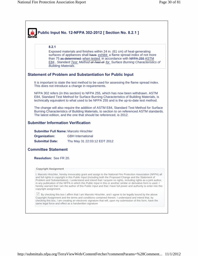
Public Input No. 12-NFPA 302-2012 [ Section No. 8.2.1 ]
8.2.1 Exposed materials and finishes within 24 in. (61 cm) of heat-generating surfaces of appliances shall have exhibit a flame spread index of not more than 75 as determined when tested in accordance with NFPA 255 ASTM E84 , Standard Test Method of Test of for Surface Burning Characteristics of Building Materials.
Statement of Problem and Substantiation for Public Input
It is important to state the test method to be used for assessing the flame spread index. This does not introduce a change in requirements.
NFPA 302 refers (in this section) to NFPA 255, which has now been withdrawn. ASTM E84, Standard Test Method for Surface Burning Characteristics of Building Materials, is technically equivalent to what used to be NFPA 255 and is the up-to-date test method.
The change will also require the addition of ASTM E84, Standard Test Method for Surface Burning Characteristics of Building Materials, to section to on referenced ASTM standards. The latest edition, and the one that should be referenced, is 2012.
Submitter Information Verification
Submitter Full Name: Marcelo Hirschler
Organization: GBH International
Submittal Date: Thu May 31 22:03:12 EDT 2012
Committee Statement
Resolution: See FR 20.
Copyright Assignment
I, Marcelo Hirschler, hereby irrevocably grant and assign to the National Fire Protection Association (NFPA) all and full rights in copyright in this Public Input (including both the Proposed Change and the Statement of Problem and Substantiation). I understand and intend that I acquire no rights, including rights as a joint author, in any publication of the NFPA in which this Public Input in this or another similar or derivative form is used. I hereby warrant that I am the author of this Public Input and that I have full power and authority to enter into this copyright assignment.
By checking this box I affirm that I am Marcelo Hirschler, and I agree to be legally bound by the above Copyright Assignment and the terms and conditions contained therein. I understand and intend that, bychecking this box, I am creating an electronic signature that will, upon my submission of this form, have the same legal force and effect as a handwritten signature
Page 30 of 81National Fire Protection Association Report
11/1/2012http://submittals.nfpa.org/TerraViewWeb/ContentFetcher?commentParams=%28Comment...

Public Input No. 9-NFPA 302-2012 [ Section No. 8.2.2 ]
8.2.2 Fabrics located above and within 39 in. (1 m) of a galley stove top, used for decorative or other purposes, shall be flame resistant in accordance with meet the flame propagation performance criteria contained in Test Method 1 or Test Method 2, as appropriate, of NFPA 701, Standard Methods of Fire Tests for Flame Propagation of Textiles and Films.
Statement of Problem and Substantiation for Public Input
Page 31 of 81National Fire Protection Association Report
11/1/2012http://submittals.nfpa.org/TerraViewWeb/ContentFetcher?commentParams=%28Comment...
The term "flame resistant" has been changed in most NFPA and ICC codes by the phrase "meet the flame propagation performance criteria" because it is more accurate and because the term flame resistant is vague and unenforceable.
The remainder of the proposed change is explained below and is being implemented in other codes and standards also.
In 1989 the NFPA Technical Committee on Fire Tests eliminated the so-called “small-scale test” from NFPA 701 because the results had been shown not to represent a fire performance that corresponded to what happened in real scale. Instead of the “small-scale test” NFPA 701 now (and for over 20 years) contains two tests (Test 1 and Test 2), which apply to materials as indicated by the text of NFPA 701 (2010) that is shown at the bottom of this public input.
However, a large number of manufacturers continue stating that the materials or products that they sell have been tested to NFPA 701, when they really mean the pre-1989 small-scale test in NFPA 701. That test no longer exists and materials or products meeting that test do not exhibit acceptable fire performance.
Text of NFPA 701 (2010):1.1.1.1 Test Method 1 shall apply to fabrics or other materials used in curtains, draperies, or other window treatments. Vinyl-coated fabric blackout linings shall be tested according to Test Method 2.1.1.1.2 Test Method 1 shall apply to single-layer fabrics and to multilayer curtain and drapery assemblies in which the layers are fastened together by sewing or other means. Vinyl-coated fabric blackout linings shall be tested according to Test Method 2.1.1.1.3 Test Method 1 shall apply to specimens having an areal density less than or equal to 700 g/m2 (21 oz/yd2), except where Test Method 2 is required to be used by 1.1.2.
1.1.2.1 Test Method 2 (flat specimen configuration) shall be used for fabrics, including multilayered fabrics, films, and plastic blinds, with or without reinforcement or backing, with areal densities greater than 700 g/m2 (21 oz/yd2).1.1.2.2 Test Method 2 shall be used for testing vinyl-coated fabric blackout linings and lined draperies using a vinyl-coated fabric blackout lining.1.1.2.3 Test Method 2 shall be used for testing plastic films, with or without reinforcement or backing, when used for decorative or other purposes inside a building or as temporary or permanent enclosures for buildings under construction.1.1.2.4 Test Method 2 shall apply to fabrics used in the assembly of awnings, tents, tarps, and similar architectural fabric structures and banners.
Note also the following from the text of NFPA 701 (2010):1.2* Purpose.1.2.1 The purpose of Test Methods 1 and 2 shall be to assess the propagation of flame beyond the area exposed to the ignition source.
A.1.1 A small-scale test method appeared in NFPA 701 until the 1989 edition. It was eliminated from the test method because it has been shown that materials that “pass” the test do not necessarily exhibit a fire performance that is acceptable. The test was not reproducible for many types of fabrics and could not predict actual full-scale performance. It should not, therefore, be used.A.1.1.1 For the purposes of Test Method 1, the terms curtains, draperies, or other types of window treatments, where used, should include, but not be limited to, the following items:(1) Window curtains(2) Stage or theater curtains(3) Vertical folding shades(4) Roll-type window shades(5) Hospital privacy curtains(6) Window draperies(7) Fabric shades or blinds(8) Polyvinyl chloride blinds
Page 32 of 81National Fire Protection Association Report
11/1/2012http://submittals.nfpa.org/TerraViewWeb/ContentFetcher?commentParams=%28Comment...

(9) Horizontal folding shades(10) SwagsExamples of textile items other than window treatments to which Test Method 1 applies include:(1) Table skirts(2) Table linens(3) Display booth separators(4) Textile wall hangings(5) Decorative event tent linings not used in the assembly of a tent
Submitter Information Verification
Submitter Full Name: Marcelo Hirschler
Organization: GBH International
Submittal Date: Thu May 31 21:44:32 EDT 2012
Committee Statement
Page 33 of 81National Fire Protection Association Report
11/1/2012http://submittals.nfpa.org/TerraViewWeb/ContentFetcher?commentParams=%28Comment...
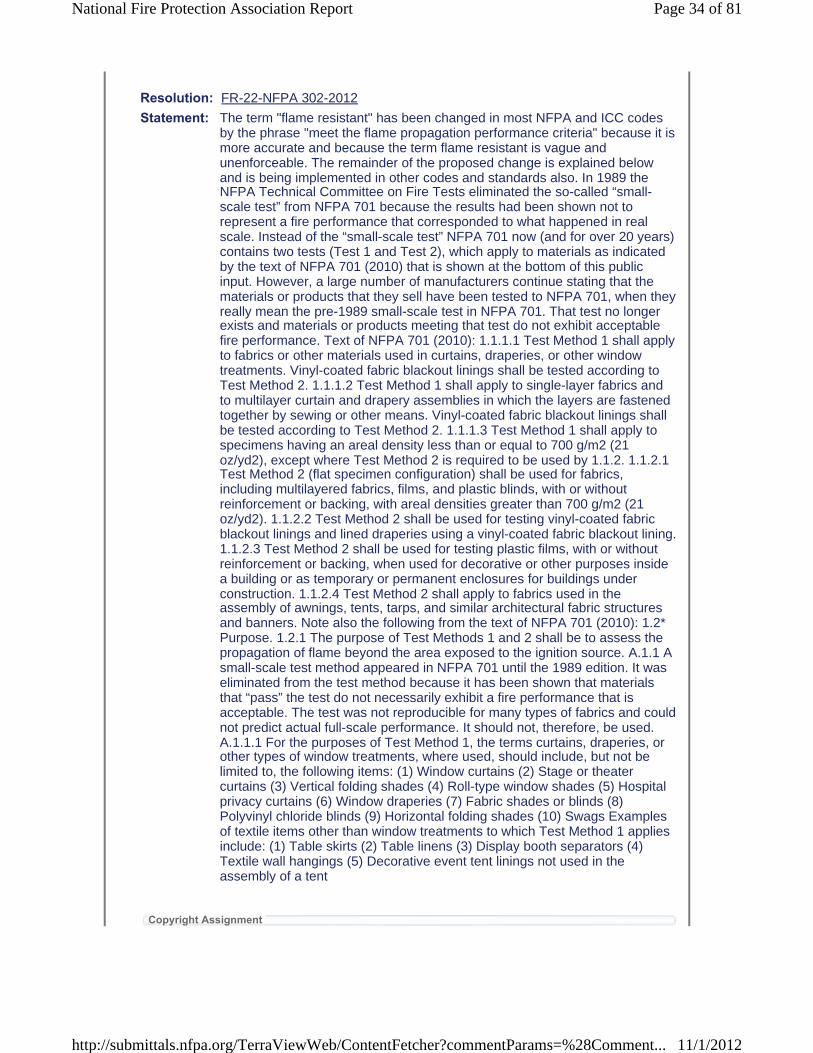
Resolution: FR-22-NFPA 302-2012
Statement: The term "flame resistant" has been changed in most NFPA and ICC codes by the phrase "meet the flame propagation performance criteria" because it is more accurate and because the term flame resistant is vague and unenforceable. The remainder of the proposed change is explained below and is being implemented in other codes and standards also. In 1989 the NFPA Technical Committee on Fire Tests eliminated the so-called “small-scale test” from NFPA 701 because the results had been shown not to represent a fire performance that corresponded to what happened in real scale. Instead of the “small-scale test” NFPA 701 now (and for over 20 years) contains two tests (Test 1 and Test 2), which apply to materials as indicated by the text of NFPA 701 (2010) that is shown at the bottom of this public input. However, a large number of manufacturers continue stating that the materials or products that they sell have been tested to NFPA 701, when they really mean the pre-1989 small-scale test in NFPA 701. That test no longer exists and materials or products meeting that test do not exhibit acceptable fire performance. Text of NFPA 701 (2010): 1.1.1.1 Test Method 1 shall apply to fabrics or other materials used in curtains, draperies, or other windowtreatments. Vinyl-coated fabric blackout linings shall be tested according to Test Method 2. 1.1.1.2 Test Method 1 shall apply to single-layer fabrics and to multilayer curtain and drapery assemblies in which the layers are fastened together by sewing or other means. Vinyl-coated fabric blackout linings shall be tested according to Test Method 2. 1.1.1.3 Test Method 1 shall apply to specimens having an areal density less than or equal to 700 g/m2 (21 oz/yd2), except where Test Method 2 is required to be used by 1.1.2. 1.1.2.1 Test Method 2 (flat specimen configuration) shall be used for fabrics, including multilayered fabrics, films, and plastic blinds, with or without reinforcement or backing, with areal densities greater than 700 g/m2 (21 oz/yd2). 1.1.2.2 Test Method 2 shall be used for testing vinyl-coated fabric blackout linings and lined draperies using a vinyl-coated fabric blackout lining. 1.1.2.3 Test Method 2 shall be used for testing plastic films, with or without reinforcement or backing, when used for decorative or other purposes inside a building or as temporary or permanent enclosures for buildings under construction. 1.1.2.4 Test Method 2 shall apply to fabrics used in the assembly of awnings, tents, tarps, and similar architectural fabric structures and banners. Note also the following from the text of NFPA 701 (2010): 1.2*Purpose. 1.2.1 The purpose of Test Methods 1 and 2 shall be to assess thepropagation of flame beyond the area exposed to the ignition source. A.1.1 A small-scale test method appeared in NFPA 701 until the 1989 edition. It was eliminated from the test method because it has been shown that materials that “pass” the test do not necessarily exhibit a fire performance that is acceptable. The test was not reproducible for many types of fabrics and could not predict actual full-scale performance. It should not, therefore, be used. A.1.1.1 For the purposes of Test Method 1, the terms curtains, draperies, or other types of window treatments, where used, should include, but not be limited to, the following items: (1) Window curtains (2) Stage or theater curtains (3) Vertical folding shades (4) Roll-type window shades (5) Hospital privacy curtains (6) Window draperies (7) Fabric shades or blinds (8) Polyvinyl chloride blinds (9) Horizontal folding shades (10) Swags Examples of textile items other than window treatments to which Test Method 1 applies include: (1) Table skirts (2) Table linens (3) Display booth separators (4) Textile wall hangings (5) Decorative event tent linings not used in the assembly of a tent
Copyright Assignment
Page 34 of 81National Fire Protection Association Report
11/1/2012http://submittals.nfpa.org/TerraViewWeb/ContentFetcher?commentParams=%28Comment...
I, Marcelo Hirschler, hereby irrevocably grant and assign to the National Fire Protection Association (NFPA) all and full rights in copyright in this Public Input (including both the Proposed Change and the Statement of Problem and Substantiation). I understand and intend that I acquire no rights, including rights as a joint author, in any publication of the NFPA in which this Public Input in this or another similar or derivative form is used. I hereby warrant that I am the author of this Public Input and that I have full power and authority to enter into this copyright assignment.
By checking this box I affirm that I am Marcelo Hirschler, and I agree to be legally bound by the above Copyright Assignment and the terms and conditions contained therein. I understand and intend that, bychecking this box, I am creating an electronic signature that will, upon my submission of this form, have the same legal force and effect as a handwritten signature
Page 35 of 81National Fire Protection Association Report
11/1/2012http://submittals.nfpa.org/TerraViewWeb/ContentFetcher?commentParams=%28Comment...
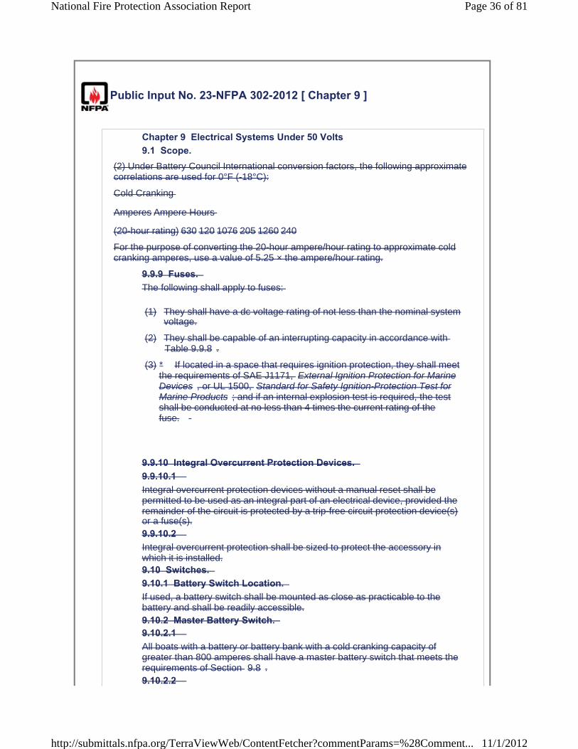
Public Input No. 23-NFPA 302-2012 [ Chapter 9 ]
Chapter 9 Electrical Systems Under 50 Volts 9.1 Scope.
(2) Under Battery Council International conversion factors, the following approximatecorrelations are used for 0°F (-18°C):
Cold Cranking
Amperes Ampere Hours
(20-hour rating) 630 120 1076 205 1260 240
For the purpose of converting the 20-hour ampere/hour rating to approximate cold cranking amperes, use a value of 5.25 × the ampere/hour rating.
9.9.9 Fuses. The following shall apply to fuses:
(1) They shall have a dc voltage rating of not less than the nominal system voltage.
(2) They shall be capable of an interrupting capacity in accordance with Table 9.9.8 .
(3)
9.9.10 Integral Overcurrent Protection Devices. 9.9.10.1 Integral overcurrent protection devices without a manual reset shall be permitted to be used as an integral part of an electrical device, provided the remainder of the circuit is protected by a trip-free circuit protection device(s) or a fuse(s).9.9.10.2 Integral overcurrent protection shall be sized to protect the accessory in which it is installed.9.10 Switches. 9.10.1 Battery Switch Location. If used, a battery switch shall be mounted as close as practicable to the battery and shall be readily accessible.9.10.2 Master Battery Switch. 9.10.2.1 All boats with a battery or battery bank with a cold cranking capacity of greater than 800 amperes shall have a master battery switch that meets the requirements of Section 9.8 .9.10.2.2
* If located in a space that requires ignition protection, they shall meet the requirements of SAE J1171, External Ignition Protection for Marine Devices , or UL 1500, Standard for Safety Ignition-Protection Test for Marine Products ; and if an internal explosion test is required, the test shall be conducted at no less than 4 times the current rating of thefuse.
Page 36 of 81National Fire Protection Association Report
11/1/2012http://submittals.nfpa.org/TerraViewWeb/ContentFetcher?commentParams=%28Comment...

Electronic devices with protected memory and protective devices, such as bilge pumps and protected alarm systems, shall be permitted to be connected to the continuously energized side of the switch required in9.10.2.1 .9.10.3 Battery Switch Ratings. 9.10.3.1 The intermittent rating of a battery switch shall be not less than the maximum cranking current of the largest engine cranking motor it serves.9.10.3.2 The continuous rating of a battery switch shall be not less than the total of the ampacities of the main overcurrent protection devices connected to the battery switch.9.10.4 Branch Circuit Switches. Single-pole switches used in branch circuits, except for the following, shall be installed in the positive conductor of the circuit:
(1) Engine-mounted pressure, vacuum, and temperature-operated switches
(2) Switches used for control of alarm systems
9.10.5 * Voltage Rating. Switches shall have a voltage rating of no less than the system voltage.9.10.6 Current Rating. Switches shall have a current rating of no less than the connected load.9.11 Appliances and Equipment. 9.11.1 Current-Carrying Parts. 9.11.1.1 Appliances and fixed dc electrical equipment, other than devices identified in 9.11.1.2 and 9.11.1.3 , shall be designed so that the current-carrying parts of the devices are insulated from all exposed electrically conductive parts.9.11.1.2 Engine-mounted equipment shall be permitted to have their negative conductors connected to exposed electrically conductive parts.9.11.1.3 Specific Devices. 9.11.1.3.1 The following devices shall be permitted to have their negative conductors connected to exposed electrically conductive parts:
(1) Communications and audio equipment
(2) Electronic navigation equipment
(3) Instruments and instrument clusters
(4) Cigarette lighters
(5) Liquid level gauge transmitters (for installation on conductive surfaces)
(6) Navigation lights operating at nominal 12 volts or less
9.11.1.3.2
Page 37 of 81National Fire Protection Association Report
11/1/2012http://submittals.nfpa.org/TerraViewWeb/ContentFetcher?commentParams=%28Comment...

If a device identified in 9.11.1.3.1 has negative conductors connected to exposed electrically conductive parts, the device shall meet the following criteria:
(1) The polarity of both the positive and negative connections shall be identified.
(2) It shall be mounted only on electrically nonconductive material.
(3) It shall not be bonded.
9.11.2 Grounded Liquid Level Gauge Transmitters (Senders). 9.11.2.1 Grounded liquid level gauge transmitters mounted on metallic tanks or tank plates shall have the transmitter negative return conductor connected directly to the engine negative terminal, its bus, or, for outboard boats, the battery negative terminal.9.11.2.2 The transmitter negative return conductor shall serve as the static ground or the bonding conductor, or both.9.11.2.3 If the transmitter negative return conductor is used as the tank system bonding conductor, it shall be minimum No. 8 AWG.9.11.2.4 No device or component other than a grounded liquid level gauge transmitter, tank, tank fill components, or tank vent components shall beconnected to the transmitter negative return conductor or statically grounded to the tank.9.11.3 Pigtail connections on submersible devices such as submersible bilge pumps shall not be shorter in length than 16 in. (41 cm).9.11.4 Battery chargers and their installation shall comply with the requirements of ABYC A-31, Battery Chargers and Inverters .9.11.5 Inverters. 9.11.5.1 Inverters and their installation shall comply with the requirements of ABYC A-31, Battery Chargers and Inverters .9.11.5.2
Inverter chargers and their installation shall comply with the requirements of 9.1.1 The standards and practices of this chapter shall apply to the design and installation of direct current (dc) electrical systems on boats that operate at potentials of 50 volts or less except for the systems addressed in 9.1.2 .9.1.2 The standards and practices of this chapter shall not apply to any wire permanently attached to an outboard engine and extending not more than 72 in. (183 cm) from the outboard engine.9.2 General Requirements. 9.2.1 Conductor Length Measurement. All lengths for conductors shall be measured along the conductors.9.2.2 * Two-Wire System. 9.2.2.1
Page 38 of 81National Fire Protection Association Report
11/1/2012http://submittals.nfpa.org/TerraViewWeb/ContentFetcher?commentParams=%28Comment...

Branch circuits shall be of the two-wire type and shall use insulated conductors to and from each item of equipment unless permitted otherwise by 9.2.2.4 or 9.2.2.5 .9.2.2.2 The feed and return wires for the circuits of 9.2.2.1 shall be run together from the power source to the equipment.9.2.2.3 If a common return is used for the circuits of 9.2.2.1 , it shall be of equal wire gauge to the panelboard feeder.9.2.2.4 The electrical system on a propulsion or auxiliary engine shall be permitted to be of the one-wire type, with the negative side of the system connected directly to the engine block.9.2.2.5 The accessory negative bus of an outboard engine shall be permitted to be connected to the battery.9.2.3 Return Circuit. A metal hull, bonding conductor, or grounding conductor shall not be used as a return circuit unless permitted otherwise by Section 9.11 .9.2.4 Grounded Systems. If one side of a two-wire dc system is connected to ground, it shall be the negative side, and the system shall be polarized.9.2.5 Multiple Engine Installation. 9.2.5.1 If a boat has more than one inboard propulsion or auxiliary engine, grounded cranking motor circuits shall be connected to each other by a common conductor that can carry the starting current of each of the grounded cranking motor circuits.9.2.5.2 Outboard engines shall be connected at the battery negatives.9.2.6 Crossover (Parallel) Cranking Motor Circuits. 9.2.6.1 In multiple inboard engine installations (including auxiliary generators) with crossover (parallel) cranking motor systems, the engines shall be connected together with a cable except for where the installation uses ungrounded dc electrical systems.9.2.6.2 The cable required by 9.2.6.1 shall be large enough to carry the cranking motor current of the largest cranking motor.9.2.6.3 The cable required by 9.2.6.1 and its terminations shall be in addition to, and independent of, any other electrical connections to the engines, including those required in 9.2.5 .9.3 Batteries. 9.3.1 Batteries shall be accessible for inspection and maintenance.9.3.2 Batteries shall not be tapped for voltages other than the total voltage of all the cells comprising the battery.9.3.3 *A vent system or other means shall be provided to allow hydrogen gas released by the battery to discharge from the boat.9.3.4
Page 39 of 81National Fire Protection Association Report
11/1/2012http://submittals.nfpa.org/TerraViewWeb/ContentFetcher?commentParams=%28Comment...
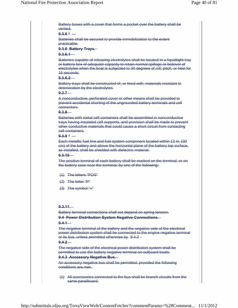
Battery boxes with a cover that forms a pocket over the battery shall be vented.9.3.5 *Batteries shall be secured to provide immobilization to the extent practicable.9.3.6 Battery Trays. 9.3.6.1 Batteries capable of releasing electrolytes shall be located in a liquidtight tray or battery box of adequate capacity to retain normal spillage or boilover of electrolytes when the boat is subjected to 30 degrees of roll, pitch, or heel for 15 seconds.9.3.6.2 Battery trays shall be constructed of, or lined with, materials resistant to deterioration by the electrolytes.9.3.7 A nonconductive, perforated cover or other means shall be provided to prevent accidental shorting of the ungrounded battery terminals and cell connectors.9.3.8 Batteries with metal cell containers shall be assembled in nonconductive trays having insulated cell supports, and provision shall be made to prevent other conductive materials that could cause a short circuit from contacting cell containers.9.3.9 *Each metallic fuel line and fuel system component located within 12 in. (30 cm) of the battery and above the horizontal plane of the battery top surface, as installed, shall be shielded with dielectric material.9.3.10 The positive terminal of each battery shall be marked on the terminal, or on the battery case near the terminal, by one of the following:
(1) The letters “POS”
(2) The letter “P”
(3) The symbol “+”
9.3.11 Battery terminal connections shall not depend on spring tension.9.4 Power Distribution System Negative Connections. 9.4.1 The negative terminal of the battery and the negative side of the electrical power distribution system shall be connected to the engine negative terminal or its bus, unless permitted otherwise by 9.4.2 .9.4.2 The negative side of the electrical power distribution system shall be permitted to use the battery negative terminal on outboard boats.9.4.3 Accessory Negative Bus. An accessory negative bus shall be permitted, provided the following conditions are met:
(1) All accessories connected to the bus shall be branch circuits from the same panelboard.
Page 40 of 81National Fire Protection Association Report
11/1/2012http://submittals.nfpa.org/TerraViewWeb/ContentFetcher?commentParams=%28Comment...

(2) Negative buses, negative bus return conductors, and their terminals and connections shall have an ampacity equal to the panelboard feeder.
(3) Negative return conductors from the panelboard feeding the branch circuits that use the accessory negative bus shall be equal in size to the positive feeder to the panelboard.
9.5 Continuously Energized Parts. 9.5.1 Continuously energized parts other than those addressed in 9.5.2 , such asthe positive battery terminal and both ends of all wires connected thereto,shall be physically protected by boots, sleeving, or other insulation to preventan accidental short.9.5.2 The protection specified in 9.5.1 shall not apply to conductors that have overcurrent protection at the source of power in accordance with Section 9.9 .9.6 Marking. 9.6.1 Marking of Controls. 9.6.1.1 Switches and electrical controls shall be marked to indicate their use unless otherwise permitted by 9.6.1.2 .9.6.1.2 A switch or electrical control shall not be required to be marked where it meets the following criteria:
(1) Its purpose is obvious.
(2) Its erroneous operation cannot cause a hazardous condition.
9.6.2 * Marking of Equipment. Electrical equipment, unless it is part of an identified assembly, shall be marked or identified by the manufacturer to indicate the following:
(1) Manufacturer
(2) Identifying number
(3) Electrical rating (dc) in volts
(4) Terminal polarity or identification, if necessary to operation
(5) Ignition protection, if applicable
9.6.3 Rated Current. 9.6.3.1 The rated current of electrical equipment, unless it is part of an identified assembly, shall be made available.9.6.3.2 Marking the device with the rated current shall be permitted to meet the requirements of 9.6.3.1 .
Page 41 of 81National Fire Protection Association Report
11/1/2012http://submittals.nfpa.org/TerraViewWeb/ContentFetcher?commentParams=%28Comment...
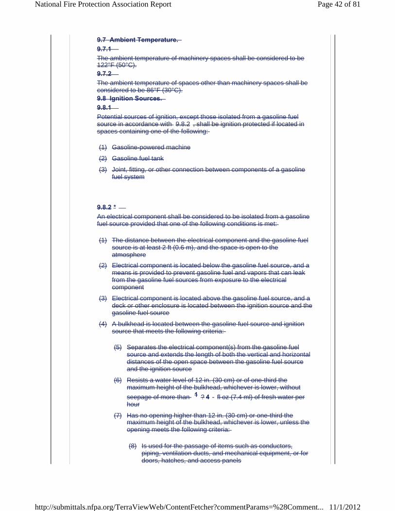
9.7 Ambient Temperature. 9.7.1 The ambient temperature of machinery spaces shall be considered to be 122°F (50°C).9.7.2 The ambient temperature of spaces other than machinery spaces shall be considered to be 86°F (30°C).9.8 Ignition Sources. 9.8.1 Potential sources of ignition, except those isolated from a gasoline fuel source in accordance with 9.8.2 , shall be ignition protected if located in spaces containing one of the following:
(1) Gasoline-powered machine
(2) Gasoline fuel tank
(3) Joint, fitting, or other connection between components of a gasoline fuel system
9.8.2 *An electrical component shall be considered to be isolated from a gasoline fuel source provided that one of the following conditions is met:
(1) The distance between the electrical component and the gasoline fuel source is at least 2 ft (0.6 m), and the space is open to the atmosphere
(2) Electrical component is located below the gasoline fuel source, and a means is provided to prevent gasoline fuel and vapors that can leak from the gasoline fuel sources from exposure to the electrical component
(3) Electrical component is located above the gasoline fuel source, and a deck or other enclosure is located between the ignition source and the gasoline fuel source
(4) A bulkhead is located between the gasoline fuel source and ignition source that meets the following criteria:
(5) Separates the electrical component(s) from the gasoline fuel source and extends the length of both the vertical and horizontal distances of the open space between the gasoline fuel source and the ignition source
(6) Resists a water level of 12 in. (30 cm) or of one-third the maximum height of the bulkhead, whichever is lower, without
seepage of more than 1 ? 4 fl oz (7.4 ml) of fresh water per hour
(7) Has no opening higher than 12 in. (30 cm) or one-third the maximum height of the bulkhead, whichever is lower, unless the opening meets the following criteria:
(8) Is used for the passage of items such as conductors, piping, ventilation ducts, and mechanical equipment, or for doors, hatches, and access panels
Page 42 of 81National Fire Protection Association Report
11/1/2012http://submittals.nfpa.org/TerraViewWeb/ContentFetcher?commentParams=%28Comment...

(9) Has a maximum annular space around each item passing
through it not more than 1 ? 4 in. (6.4 mm)
9.9 Overcurrent Protection. 9.9.1 General. 9.9.1.1 The distances specified in Section 9.9 shall be measured along the conductor.9.9.1.2 The requirements of 9.9.2 through 9.9.10.2 shall not apply to pigtails less than 7 in. (18 cm) in length.9.9.2 * Overcurrent Protection Location. Conductors other than cranking motor conductors shall be provided with overcurrent protection at the source of power unless permitted by 9.9.2.1 ,9.9.2.2 , or 9.9.2.3 .9.9.2.1 Where not practical to locate overcurrent protection at the source of power, conductors other than cranking motor conductors shall be provided with overcurrent protection no more than 7 in. (18 cm) from the point at which the conductor is connected to the source of power measured along theconductor.9.9.2.2 If the conductor is contained in a sheath or enclosure, such as a junction box, control box, or enclosed panel, throughout the required distance, and where not practical to locate overcurrent protection at the source of power, conductors other than cranking motor conductors shall be provided withovercurrent protection no more than 40 in. (102 cm) from the point at which the conductor is connected to the source of power.9.9.2.3 If the conductor is connected directly to the battery terminal, and where not practical to locate overcurrent protection at the source of power, conductors other than cranking motor conductors shall be provided with overcurrent protection no more than 72 in. (183 cm) from the battery terminal.9.9.3 Charging Sources. 9.9.3.1 *Only battery charging sources designed to meet the requirements of the battery manufacturer shall be used for charging.9.9.3.2 Overcurrent Protection of Conductors. 9.9.3.2.1 Each ungrounded dc conductor that runs from the battery charger or other charging source to a battery or other point of connection to the dc system shall be provided with overcurrent protection within a distance of 7 in. (18 cm) from the point of connection to the dc electrical system or battery, unless otherwise permitted by 9.9.3.2.2 , 9.9.3.2.3 , or 9.9.3.2.4 .9.9.3.2.2
Page 43 of 81National Fire Protection Association Report
11/1/2012http://submittals.nfpa.org/TerraViewWeb/ContentFetcher?commentParams=%28Comment...

Where a conductor specified in 9.9.3.2.1 is connected directly to the battery terminal and is contained throughout its entire distance in a sheath or enclosure such as a conduit, junction box, control box, or enclosed panel, the overcurrent protection shall be placed no more than 72 in. (183 cm) from the battery.9.9.3.2.3 Where a conductor specified in 9.9.3.2.1 is connected to a source of power other than the battery terminal and is contained in a sheath or enclosure such as a conduit, junction box, control box, or enclosed panel, the overcurrent protection shall be placed no more than 40 in. (102 cm) from the point of connection.9.9.3.2.4 Overcurrent protection is not required in conductors from self-limiting alternators with integral regulators if the following criteria are met:
(1) The conductor is no more than 40 in. (102 cm).
(2) The conductor is connected to a source of power other than the battery.
(3) The conductor is contained throughout its entire distance in a sheath or enclosure.
9.9.3.3 Overcurrent Protection within Charging Source. 9.9.3.3.1 Unless otherwise permitted by 9.9.3.3.2 , each ungrounded dc output conductor shall be provided with overcurrent protection both within the charging source that is based on the maximum output and at the point of connection to the dc system or battery based on the conductor size.9.9.3.3.2 Self-limiting devices that are not capable of producing current in excess of the current rating of the connecting conductors shall not require overcurrent protection for the dc output conductors but do require overcurrent protection at the point of connection to the dc system or battery.9.9.4 Motors and Motor-Operated Equipment. 9.9.4.1 *Motors and motor-operated equipment, except for engine cranking motors, shall be protected internally at the equipment or by branch-circuit overcurrent devices suitable for motor current.9.9.4.2 *The protection required in 9.9.4.1 shall preclude a fire hazard if the circuit, as installed, is energized for 7 hours under any conditions of overload, including locked rotor.9.9.5 Overcurrent Protection Device Rating. The rating of overcurrent protection devices used to protect both the conductor and a load other than a dc motor shall not exceed 150 percent of the current-carrying capacity of the conductor being protected.9.9.6 Branch Circuits. Each ungrounded conductor of a branch circuit shall be provided with overcurrent protection at the point of connection to the panelboard, unless the main circuit breaker or fuse provides such protection.9.9.7 * Distribution Panels, Panelboards, and Switchboards (Panelboards). 9.9.7.1
Page 44 of 81National Fire Protection Association Report
11/1/2012http://submittals.nfpa.org/TerraViewWeb/ContentFetcher?commentParams=%28Comment...
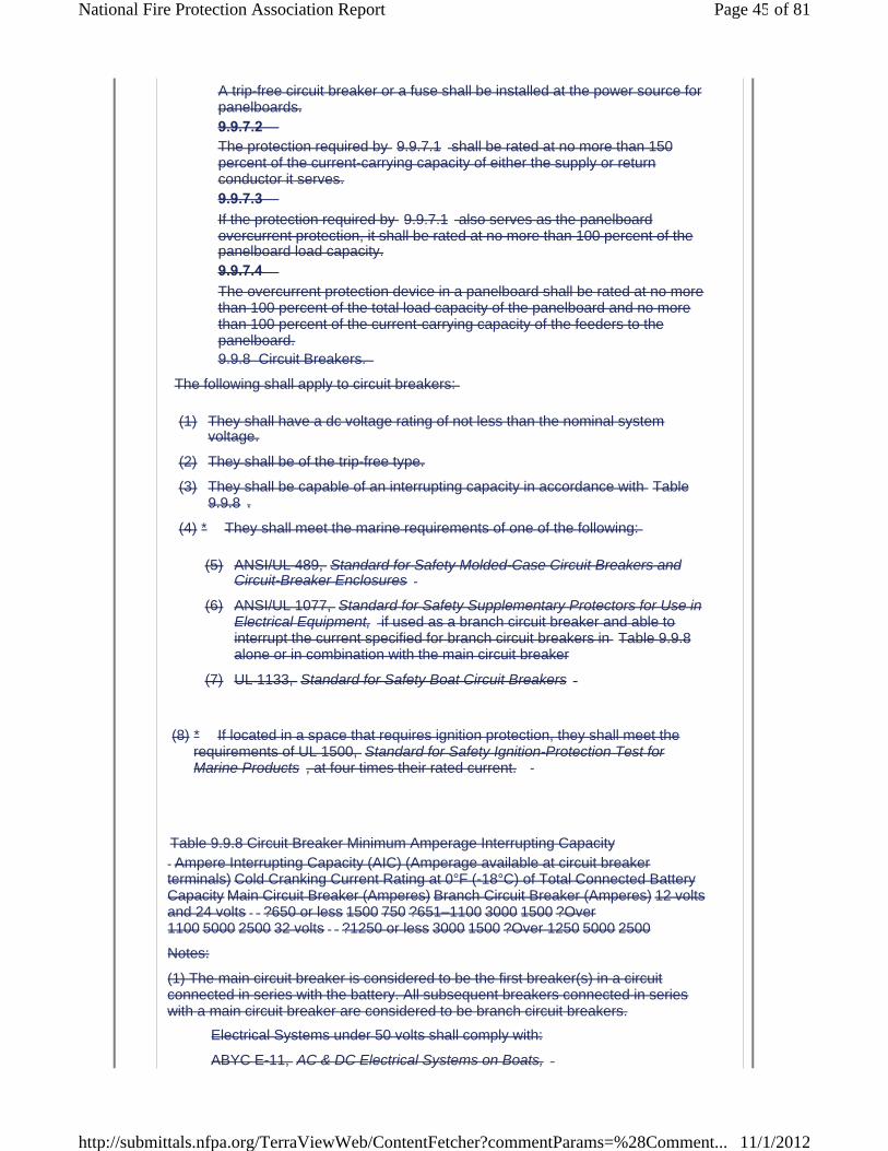
A trip-free circuit breaker or a fuse shall be installed at the power source for panelboards.9.9.7.2 The protection required by 9.9.7.1 shall be rated at no more than 150 percent of the current-carrying capacity of either the supply or return conductor it serves.9.9.7.3 If the protection required by 9.9.7.1 also serves as the panelboard overcurrent protection, it shall be rated at no more than 100 percent of the panelboard load capacity.9.9.7.4 The overcurrent protection device in a panelboard shall be rated at no more than 100 percent of the total load capacity of the panelboard and no more than 100 percent of the current-carrying capacity of the feeders to the panelboard.9.9.8 Circuit Breakers.
The following shall apply to circuit breakers:
(1) They shall have a dc voltage rating of not less than the nominal systemvoltage.
(2) They shall be of the trip-free type.
(3) They shall be capable of an interrupting capacity in accordance with Table 9.9.8 .
(4)
Table 9.9.8 Circuit Breaker Minimum Amperage Interrupting Capacity
Notes:
(1) The main circuit breaker is considered to be the first breaker(s) in a circuit connected in series with the battery. All subsequent breakers connected in series with a main circuit breaker are considered to be branch circuit breakers.
Electrical Systems under 50 volts shall comply with:
ABYC E-11, AC & DC Electrical Systems on Boats,
(8)
(5) ANSI/UL 489, Standard for Safety Molded-Case Circuit Breakers and Circuit-Breaker Enclosures
(6) ANSI/UL 1077, Standard for Safety Supplementary Protectors for Use in Electrical Equipment, if used as a branch circuit breaker and able to interrupt the current specified for branch circuit breakers in Table 9.9.8alone or in combination with the main circuit breaker
(7) UL 1133, Standard for Safety Boat Circuit Breakers
* They shall meet the marine requirements of one of the following:
* If located in a space that requires ignition protection, they shall meet the requirements of UL 1500, Standard for Safety Ignition-Protection Test for Marine Products , at four times their rated current.
Ampere Interrupting Capacity (AIC) (Amperage available at circuit breaker terminals) Cold Cranking Current Rating at 0°F (-18°C) of Total Connected Battery Capacity Main Circuit Breaker (Amperes) Branch Circuit Breaker (Amperes) 12 volts and 24 volts ?650 or less 1500 750 ?651–1100 3000 1500 ?Over 1100 5000 2500 32 volts ?1250 or less 3000 1500 ?Over 1250 5000 2500
Page 45 of 81National Fire Protection Association Report
11/1/2012http://submittals.nfpa.org/TerraViewWeb/ContentFetcher?commentParams=%28Comment...

ABYC E-10, Storage Batteries,
ABYC A-31, Battery Chargers and Inverters .
9.12.1 Conductors and flexible cords shall have a minimum rating of 50 volts.9.12.2 *The construction of insulated cables and conductors shall conform with the requirements of SAE J1127, Standard for Low Voltage Battery Cable ; SAE J1128, Standard for Low Tension Primary Cable ; or UL 1426, Standard for Safety Electrical Cables for Boats .9.12.3
Conductors shall be permitted to be selected from the types provided in Table 9.12.3(a) and Table 9.12.3(b) .
Table 9.12.3(a) SAE Conductors
Source: SAE J378, Recommended Practice for Marine Engine Wiring .
Note: The temperature ratings shown assume the routing of wires above bilge water in locations protected from dripping, exposure to weather, spray, and oil.
Table 9.12.3(b) Acceptable Insulation Types
* Numbers listed are style numbers.
9.12.4
Flexible cords shall conform with NFPA 70 , National Electrical Code , and shall be selected from the types specified in Table 9.12.4 .
Table 9.12.4 Flexible Cords
9.12 System Wiring.
Available Insulation Temperature Rating Type Description °C °F GPT Thermoplastic insulation, braidless 60 140 90 194 105 221 HDT Thermoplastic insulation,braidless 60 140 90 194 105 221 SGT Thermoplastic insulation,braidless 60 140 90 194 105 221 STS Thermosetting synthetic rubber insulation, braidless 85 185 90 194 HTS Thermosetting synthetic rubber insulation, braidless 85 185 90 194 SXL Thermosetting cross-linked polyethylene insulation,braidless 125 257
Available Insulation Temperature Rating Type Description °C °F THW Moisture- and heat-resistant, thermoplastic 75 167 TW Moisture-resistant,thermoplastic 60 140 THWN Moisture- and heat-resistant, thermoplastic 75 167 XHHW Moisture- and heat-resistant, cross-linked syntheticpolymer 90 194 MTW Moisture-, heat-, and oil-resistant, thermoplastic 90 194 AWM Moisture-, heat-, and oil-resistant,thermoplastic 105 221 Style Nos.:* Thermosetting 1230 1231 1275 1276 1329 1335 1336 1337 13391426 Boat cable (See UL 1426, Standard for Safety Electrical Cables for Boats.)
Type Description Insulation Temperature Rating Application SO Hard service cord—oil-resistant compound 60°C (140°F)
75°C (167°F) and higher General use except for machinery space
General use ST Hard service cord— thermoplastic 60°C (140°F)
75°C (167°F) and higher General use except for machinery space
General use STO Hard service cord—oil-resistant thermoplastic 60°C (140°F)
75°C (167°F) and higher General use except for machinery space
General use SJO Junior hard service cord—oil-resistant compound 60°C (140°F)
Page 46 of 81National Fire Protection Association Report
11/1/2012http://submittals.nfpa.org/TerraViewWeb/ContentFetcher?commentParams=%28Comment...

9.12.5
Conductors and flexible cords shall be stranded copper according to Table 9.12.5(a) and shall be sized in accordance with Table 9.12.5(b) .
Table 9.12.5(a) Conductor Circular Mil (CM) Area and Stranding
Note: Metric wire sizes are to be used if of equivalent circular mil area. If the circular mil area of the metric conductor is less than that specified, the wire ampacity can be corrected based on the ratio of the circular mil area.
a Applies only to systems under 50 volts.
b Conductors with Type 2 stranding, used for general-purpose wiring, which is subject to some movement from vibration or minor flexing.
c Conductors with Type 3 stranding, used for any wiring where flexing is involved in normal use.
Table 9.12.5(b) Allowable Amperage of Conductors for Under 50 Volts
9.12.6 Conductors and flexible cords shall be sized for voltage drop as follows:
(1) 3 percent for panelboard main feeders
(2) 3 percent for navigation light circuits
(3) 3 percent for electronic equipment circuits
(4) 3 percent for bilge pump, blower, and refrigeration motor circuits
(5) 10 percent for all noncritical circuits not identified in 9.12.6 (1)through 9.12.6 (4)
9.12.7 Conductor Sizing Formula. 9.12.7.1 Conductor sizes shall be permitted to be calculated by means of the following formula.
75°C (167°F) and higher General use except for machinery space
General use SJT Junior hard service cord—thermoplastic 60°C (140°F)
75°C (167°F) and higher General use except for machinery space
General use SJTO Junior hard service cord—thermoplastic 60°C (140°F)
75°C (167°F) and higher General use except for machinery space
General use
Conductor
Size (AWG) Minimum Acceptable
CM Area a Minimum Number of Strands Type 2 b Type 3 c 18 1,537 16 —16 2,336 19 26 14 3,702 19 41 12 5,833 19 65 10 9,343 19 105 8 14,810 19 168 6 25,910 37 266 4 37,
Temperature Rating of Conductor Insulation Conductor Size 60°C (140°F) 75°C (167°F) 80°C (176°F) 90°C (194°F) 105°C (221°F) 125°C (257°F) 200°C (392°F)English Metric Outside Engine Spaces Inside Engine Spaces Outside Engine Spaces Inside Engine Spaces Outside Engine Spaces Inside Engine Spaces Outside Engine Spaces Inside Engine Spaces Outside Engine Spaces Inside Engine Spaces Outside Engine Spaces Inside Engine Spaces Outside or Inside EngineSpaces 18 0.8 10 5.8 10 7.5 15 11.7 20 16.4 20 17.0 25 22.3 25 16 1 15 8.7 15 11.3 20 15.6 25 20.5 25
Page 47 of 81National Fire Protection Association Report
11/1/2012http://submittals.nfpa.org/TerraViewWeb/ContentFetcher?commentParams=%28Comment...

where:
CM = circular mil area of conductor
K = 10.75 (constant representing the mil-foot resistance of copper)
I = load current in amperes
L = length of conductor from the positive power source connection to the electrical device and back to the negative power source connection, measured in feet
E = voltage drop at load in volts (e.g., 12 volt @ 3 percent = 0.36)
9.12.7.2 If the circular mil area calculated in 9.12.7.1 is less than the value specified in Table 9.12.5(a) , the next larger size conductor shall be used.9.13 Wiring Installation. 9.13.1 *Current-carrying conductors shall be routed above the bilge water level and other areas where water can accumulate where the wiring and connectors are not watertight.9.13.2 *Conductors, other than wiring on engines and exhaust temperature sensor wiring, shall be routed in a manner that complies with the following criteria:
(1) There shall be a clearance of no less than 2 in. (5 cm) between conductors and water-cooled exhaust components.
(2) There shall be a clearance of no less than 9 in. (23 cm) between conductors and dry exhaust components where the conductor is not directly above the exhaust.
(3) There shall be a clearance of no less than 18 in. (46 cm) between conductors and dry exhaust components where conductors arelocated directly above the exhaust.
9.13.3 Battery Cables. 9.13.3.1 Battery cables shall not contact any metallic fuel system components.9.13.3.2 *Where contact occurs between battery cables and nonmetallic fuel system components, cables shall be secured to prevent relative motion and abrasion between the two system components.9.13.4 Physical Damage. 9.13.4.1 Conductors subject to exposure to physical damage shall be protected by loom, conduit, tape, raceways, or other equivalent protection.9.13.4.2 The protection required by 9.13.4.1 shall be self-draining.9.13.4.3 *
Page 48 of 81National Fire Protection Association Report
11/1/2012http://submittals.nfpa.org/TerraViewWeb/ContentFetcher?commentParams=%28Comment...
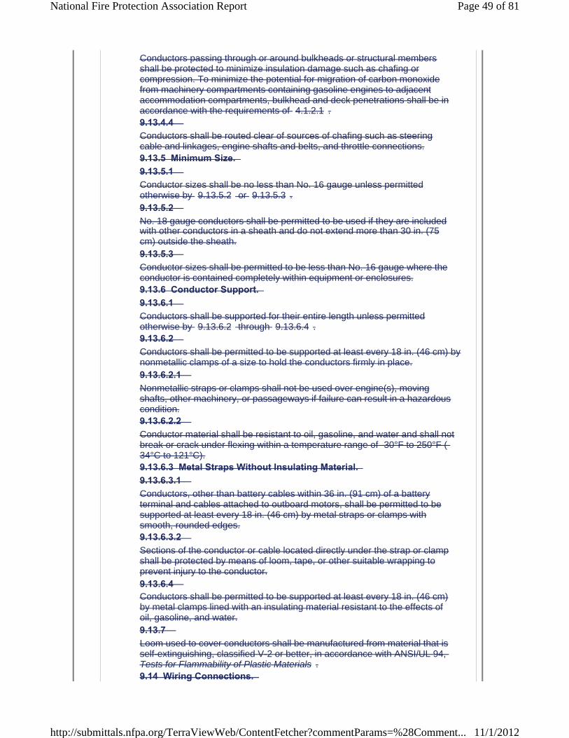
Conductors passing through or around bulkheads or structural members shall be protected to minimize insulation damage such as chafing or compression. To minimize the potential for migration of carbon monoxide from machinery compartments containing gasoline engines to adjacentaccommodation compartments, bulkhead and deck penetrations shall be inaccordance with the requirements of 4.1.2.1 .9.13.4.4 Conductors shall be routed clear of sources of chafing such as steering cable and linkages, engine shafts and belts, and throttle connections.9.13.5 Minimum Size. 9.13.5.1 Conductor sizes shall be no less than No. 16 gauge unless permitted otherwise by 9.13.5.2 or 9.13.5.3 .9.13.5.2 No. 18 gauge conductors shall be permitted to be used if they are included with other conductors in a sheath and do not extend more than 30 in. (75 cm) outside the sheath.9.13.5.3 Conductor sizes shall be permitted to be less than No. 16 gauge where the conductor is contained completely within equipment or enclosures.9.13.6 Conductor Support. 9.13.6.1 Conductors shall be supported for their entire length unless permitted otherwise by 9.13.6.2 through 9.13.6.4 .9.13.6.2 Conductors shall be permitted to be supported at least every 18 in. (46 cm) by nonmetallic clamps of a size to hold the conductors firmly in place.9.13.6.2.1 Nonmetallic straps or clamps shall not be used over engine(s), moving shafts, other machinery, or passageways if failure can result in a hazardous condition.9.13.6.2.2 Conductor material shall be resistant to oil, gasoline, and water and shall not break or crack under flexing within a temperature range of -30°F to 250°F (-34°C to 121°C).9.13.6.3 Metal Straps Without Insulating Material. 9.13.6.3.1 Conductors, other than battery cables within 36 in. (91 cm) of a battery terminal and cables attached to outboard motors, shall be permitted to be supported at least every 18 in. (46 cm) by metal straps or clamps with smooth, rounded edges.9.13.6.3.2 Sections of the conductor or cable located directly under the strap or clamp shall be protected by means of loom, tape, or other suitable wrapping to prevent injury to the conductor.9.13.6.4 Conductors shall be permitted to be supported at least every 18 in. (46 cm) by metal clamps lined with an insulating material resistant to the effects of oil, gasoline, and water.9.13.7 Loom used to cover conductors shall be manufactured from material that is self-extinguishing, classified V-2 or better, in accordance with ANSI/UL 94, Tests for Flammability of Plastic Materials .9.14 Wiring Connections.
Page 49 of 81National Fire Protection Association Report
11/1/2012http://submittals.nfpa.org/TerraViewWeb/ContentFetcher?commentParams=%28Comment...
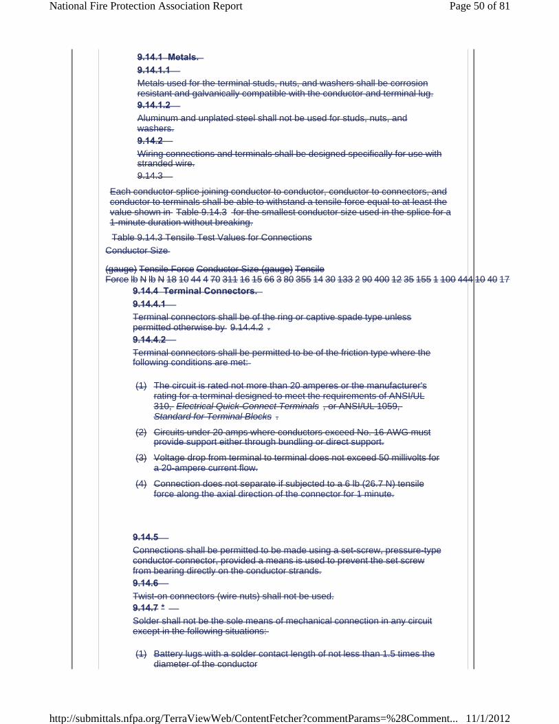
9.14.1 Metals. 9.14.1.1 Metals used for the terminal studs, nuts, and washers shall be corrosion resistant and galvanically compatible with the conductor and terminal lug.9.14.1.2 Aluminum and unplated steel shall not be used for studs, nuts, and washers.9.14.2 Wiring connections and terminals shall be designed specifically for use with stranded wire.9.14.3
Each conductor splice joining conductor to conductor, conductor to connectors, andconductor to terminals shall be able to withstand a tensile force equal to at least the value shown in Table 9.14.3 for the smallest conductor size used in the splice for a 1-minute duration without breaking.
Table 9.14.3 Tensile Test Values for Connections
9.14.4 Terminal Connectors. 9.14.4.1 Terminal connectors shall be of the ring or captive spade type unless permitted otherwise by 9.14.4.2 .9.14.4.2 Terminal connectors shall be permitted to be of the friction type where the following conditions are met:
(1) The circuit is rated not more than 20 amperes or the manufacturer's rating for a terminal designed to meet the requirements of ANSI/UL 310, Electrical Quick-Connect Terminals , or ANSI/UL 1059,Standard for Terminal Blocks .
(2) Circuits under 20 amps where conductors exceed No. 16 AWG must provide support either through bundling or direct support.
(3) Voltage drop from terminal to terminal does not exceed 50 millivolts for a 20-ampere current flow.
(4) Connection does not separate if subjected to a 6 lb (26.7 N) tensile force along the axial direction of the connector for 1 minute.
9.14.5 Connections shall be permitted to be made using a set-screw, pressure-type conductor connector, provided a means is used to prevent the set screw from bearing directly on the conductor strands.9.14.6 Twist-on connectors (wire nuts) shall not be used.9.14.7 *Solder shall not be the sole means of mechanical connection in any circuit except in the following situations:
(1) Battery lugs with a solder contact length of not less than 1.5 times the diameter of the conductor
Conductor Size
(gauge) Tensile Force Conductor Size (gauge) TensileForce lb N lb N 18 10 44 4 70 311 16 15 66 3 80 355 14 30 133 2 90 400 12 35 155 1 100 444 10 40 177
Page 50 of 81National Fire Protection Association Report
11/1/2012http://submittals.nfpa.org/TerraViewWeb/ContentFetcher?commentParams=%28Comment...

(2) Conductors contained completely within equipment or enclosures
9.14.8 Solderless crimp-on connectors shall be attached with the type of crimping tools designed for the connector used.9.14.9 Each battery terminal post shall be used for no more than one conductor and any of the following:
(1) Connections made for paralleling batteries
(2) One conductor where installed in accordance with 9.9.2
9.14.10 When a battery terminal post incorporates a threaded terminal stud, the wire size connected to the terminal stud shall not be greater than No. 2 AWG.9.14.11 No more than four conductors shall be secured to any terminal stud.9.14.12 Terminal connectors of the ring and captive spade type shall be the same nominal size as the stud.9.14.13 Conductors terminating at switchboards in junction boxes or at fixtures shall be arranged to provide a length of conductor to relieve tension, to allow for repairs, and to permit multiple conductors to be fanned at terminal studs.9.14.14 The shanks of terminals, other than those used in grounding systems, shall be protected against accidental shorting by the use of insulation barriers or sleeves.9.15 Receptacles. 9.15.1 Receptacles shall be installed in locations normally not subject to rain, spray, or flooding, or shall be protected as follows:
(1) Weatherproof if subject to rain or spray
(2) Watertight if subject to flooding
9.15.2 Receptacles and matching plugs used on dc systems shall not be interchangeable with receptacles and matching plugs used elsewhere on the boat for ac systems.9.16 Plug Connectors. Connectors used in conjunction with harness-type wiring systems shall comply with the following:
(1) Connectors shall incorporate means such as cable clamps, molded connectors, insulation grips, or extended terminal barrels to limit flexing at the connection.
Page 51 of 81National Fire Protection Association Report
11/1/2012http://submittals.nfpa.org/TerraViewWeb/ContentFetcher?commentParams=%28Comment...
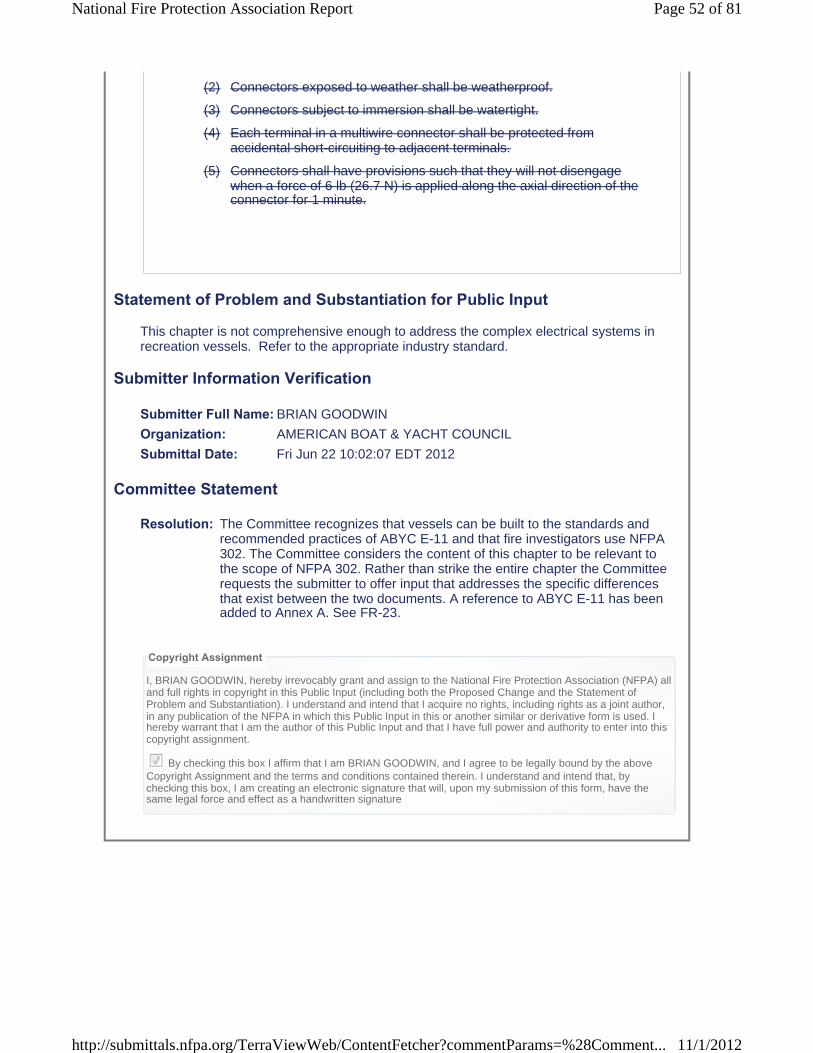
(2) Connectors exposed to weather shall be weatherproof.
(3) Connectors subject to immersion shall be watertight.
(4) Each terminal in a multiwire connector shall be protected from accidental short-circuiting to adjacent terminals.
(5) Connectors shall have provisions such that they will not disengage when a force of 6 lb (26.7 N) is applied along the axial direction of the connector for 1 minute.
Statement of Problem and Substantiation for Public Input
This chapter is not comprehensive enough to address the complex electrical systems in recreation vessels. Refer to the appropriate industry standard.
Submitter Information Verification
Submitter Full Name: BRIAN GOODWIN
Organization: AMERICAN BOAT & YACHT COUNCIL
Submittal Date: Fri Jun 22 10:02:07 EDT 2012
Committee Statement
Resolution: The Committee recognizes that vessels can be built to the standards and recommended practices of ABYC E-11 and that fire investigators use NFPA 302. The Committee considers the content of this chapter to be relevant to the scope of NFPA 302. Rather than strike the entire chapter the Committee requests the submitter to offer input that addresses the specific differences that exist between the two documents. A reference to ABYC E-11 has been added to Annex A. See FR-23.
Copyright Assignment
I, BRIAN GOODWIN, hereby irrevocably grant and assign to the National Fire Protection Association (NFPA) all and full rights in copyright in this Public Input (including both the Proposed Change and the Statement ofProblem and Substantiation). I understand and intend that I acquire no rights, including rights as a joint author, in any publication of the NFPA in which this Public Input in this or another similar or derivative form is used. I hereby warrant that I am the author of this Public Input and that I have full power and authority to enter into this copyright assignment.
By checking this box I affirm that I am BRIAN GOODWIN, and I agree to be legally bound by the above Copyright Assignment and the terms and conditions contained therein. I understand and intend that, by checking this box, I am creating an electronic signature that will, upon my submission of this form, have the same legal force and effect as a handwritten signature
Page 52 of 81National Fire Protection Association Report
11/1/2012http://submittals.nfpa.org/TerraViewWeb/ContentFetcher?commentParams=%28Comment...

Public Input No. 3-NFPA 302-2012 [ Section No. 9.13.7 ]
9.13.7 Loom used to cover conductors shall be manufactured from material that is self-extinguishing, classified V-2 or better, in accordance with ANSI/UL 94, Tests for Flammability of Plastic Materials for Parts in Devices andAppliances .
Statement of Problem and Substantiation for Public Input
Update title of ANSI/UL 94 as indicated.
Submitter Information Verification
Submitter Full Name: John Bender
Organization: Underwriters Laboratories Inc.
Submittal Date: Thu Apr 19 09:34:30 EDT 2012
Committee Statement
Resolution: FR-25-NFPA 302-2012
Statement: Update title of ANSI/UL 94 as indicated.
Copyright Assignment
I, John Bender, hereby irrevocably grant and assign to the National Fire Protection Association (NFPA) all and full rights in copyright in this Public Input (including both the Proposed Change and the Statement of Problem and Substantiation). I understand and intend that I acquire no rights, including rights as a joint author, in any publication of the NFPA in which this Public Input in this or another similar or derivative form is used. I hereby warrant that I am the author of this Public Input and that I have full power and authority to enter into this copyright assignment.
By checking this box I affirm that I am John Bender, and I agree to be legally bound by the above Copyright Assignment and the terms and conditions contained therein. I understand and intend that, by checking this box, I am creating an electronic signature that will, upon my submission of this form, have the same legal force and effect as a handwritten signature
Page 53 of 81National Fire Protection Association Report
11/1/2012http://submittals.nfpa.org/TerraViewWeb/ContentFetcher?commentParams=%28Comment...

Public Input No. 24-NFPA 302-2012 [ Chapter 10 ]
Chapter 10 Alternating Current (ac) Electrical Systems on Boats 10.1* Scope. The standards and practices of this chapter establish requirements for the design and installation of ac electrical systems on boats operating at frequencies of 50 or 60 hertz and less than 300 volts, including shore-powered systems up to the point of connection to the shore outlet.10.2 General Requirements. 10.2.1 Conductor Length Measurement. All lengths for conductors shall be measured along the conductors.10.2.2 The system shall be polarized.10.2.3 Grounded Neutral System. 10.2.3.1 A grounded neutral system shall be required unless otherwise permitted by 10.2.4 .10.2.3.2 *The neutral shall be grounded only at the power source.10.2.3.3 A shore power neutral grounded through the shore power cable shall not be grounded on the boat.10.2.4 Transformer Grounding. 10.2.4.1 On systems using an isolation or polarization transformer, the generator or inverter neutral shall be permitted to be the transformer.10.2.4.2 Secondary neutrals shall be permitted to be grounded at a main grounding bus instead of at the generator inverter or transformer secondaries.10.2.5 The boat's ac system grounding (green, or green with yellow stripe) conductor shall be connected to the engine negative terminal or its bus.10.2.6 Individual circuits shall not be capable of being energized by more than one source of electrical power at a time, and each shore power inlet or generator shall be a separate source of electrical power.10.2.7 Energized Parts. 10.2.7.1 Energized parts of electrical equipment shall be protected against accidental contact by the use of enclosures or other protective means.10.2.7.2 The protective means required in 10.2.7.1 shall not be used for nonelectrical equipment and electrical equipment together.10.2.7.3 Access to enclosures containing energized parts of electrical equipment shall require the use of hand tools.10.2.8
Page 54 of 81National Fire Protection Association Report
11/1/2012http://submittals.nfpa.org/TerraViewWeb/ContentFetcher?commentParams=%28Comment...

The transfer from one power source circuit to another shall be made by a means that opens all current-carrying conductors, including neutrals, before closing the alternate source circuit, and that prevents arc over betweensources.10.3 Marking. 10.3.1 Shore Power Inlet Warning. 10.3.1.1 A permanently mounted, waterproof warning label shall be located alongside each shore power inlet location on the boat and shall contain at a minimum the following informational elements, unless permitted otherwise by 10.3.1.2or 10.3.1.3 :
WARNING: Electrical shock and fire hazard. Failure to follow these instructions can result in injury or death.
(1) Turn off the boat's shore connection switch before connecting or disconnecting shore cable.
(2) Connect shore power cable at the boat first.
(3) Immediately disconnect cable if polarity warning indicator is activated.
(4) Disconnect shore power cable at shore outlet first.
(5) Close shore power inlet cover tightly.
(6) Do not alter shore power cable connectors.
10.3.1.2 If a polarity indicator is not required, the informational element (3) shall not be required for the label specified in 10.3.1.1 .10.3.1.3 If the shore power cable is permanently connected to the boat, the informational elements (2) and (5) shall not be required for the label specified in 10.3.1.1 .10.3.2 Marking of Controls. 10.3.2.1 Switches and electrical controls shall be marked to indicate their use unless otherwise permitted by 10.3.2.2 .10.3.2.2 A switch or electrical control shall not be required to be marked where it meets the following criteria:
(1) Its purpose is obvious.
(2) Its erroneous operation cannot cause a hazardous condition.
10.3.3 Marking of Equipment. Electrical equipment, unless it is part of an identified assembly, shall be marked or identified by the manufacturer to indicate the following:
(1) Manufacturer's identification
(2) Model number
(3) Rating in volts and amperes or volts and watts
Page 55 of 81National Fire Protection Association Report
11/1/2012http://submittals.nfpa.org/TerraViewWeb/ContentFetcher?commentParams=%28Comment...
(4) Phase identification, if applicable
(5) Ignition protection, if applicable
10.4 System Voltage. Nominal system voltages for ac electrical systems shall be one of the following:
(1) 120 volts ac, single-phase
(2) 240 volts ac, single-phase
(3) 120/240 volts ac, single-phase
(4) 120/240 volts ac, delta three-phase
(5) 120/208 volts ac, wye three-phase
10.5 Ambient Temperature. The ambient temperature of machinery spaces shall be considered to be 122°F (50°C), and the ambient temperature of all other spaces shall be considered to be 86°F (30°C).10.6 Ignition Source. 10.6.1 Potential sources of ignition, except those isolated from a gasoline fuel source in accordance with 10.6.2 , shall be ignition protected if located in spaces containing one of the following:
(1) Gasoline-powered machine
(2) Gasoline fuel tank
(3) Joint, fitting, or other connection between components of a gasoline fuel system
10.6.2 *An electrical component shall be considered to be isolated from a gasoline fuel source provided that one of the following conditions is met:
(1) The distance between the electrical component and the gasoline fuel source is at least 2 ft (0.6 m), and the space is open to the atmosphere.
(2) Electrical component is located below the gasoline fuel source, and a means is provided to prevent gasoline fuel and vapors that can leak from the gasoline fuel sources from exposure to the electrical component.
(3) Electrical component is located above the gasoline fuel source, and a deck or other enclosure is located between the ignition source and the gasoline fuel source.
(4) * A bulkhead is located between the gasoline fuel source and ignition source that meets the following criteria:
Page 56 of 81National Fire Protection Association Report
11/1/2012http://submittals.nfpa.org/TerraViewWeb/ContentFetcher?commentParams=%28Comment...
(5) Separates the electrical component(s) from the gasoline fuel source and extends the length of both the vertical and horizontal distances of the open space between the gasoline fuel source and the ignition source
(6) Resists a water level of 12 in. (30 cm) or of one-third the maximum height of the bulkhead, whichever is lower, without
seepage of more than 1 ? 4 fl oz (7.4 ml) of fresh water per hour
(7) Has no opening higher than 12 in. (30 cm) or one-third the maximum height of the bulkhead, whichever is lower, unless the opening meets the following criteria:
(8) Is used for the passage of items such as conductors, piping, ventilation ducts, and mechanical equipment, or for doors, hatches, and access panels
(9) Has a maximum annular space around each item passing
through it not more than 1 ? 4 in. (6.4 mm)
10.7 Shore Power Polarity Devices. 10.7.1 *Reverse-polarity indicating devices having a continuously visible or audible signal shall be installed in 120-volt ac shore power systems, where there is no polarization or isolation transformer that establishes the polarity of the onboard system, and one of the following conditions exists:
(1) The polarity of the system must be maintained for the proper operation of electrical devices in the system.
(2) A branch circuit is provided with overcurrent protection in the ungrounded current-carrying conductors only.
10.7.2 The total impedance of polarity-indicating and protection devices connected between normal current-carrying conductors and the grounding conductor shall be not less than 25,000 ohms at 120 volts, 60 hertz at all times.10.7.3 Conductors shall be identified to indicate polarity in accordance with Figure 10.7.3(a) through Figure 10.7.3(i) .Figure 10.7.3(a) Single-Phase 120-Volt Auxiliary Generator Shore Power Selector Switch Circuit.
Page 57 of 81National Fire Protection Association Report
11/1/2012http://submittals.nfpa.org/TerraViewWeb/ContentFetcher?commentParams=%28Comment...
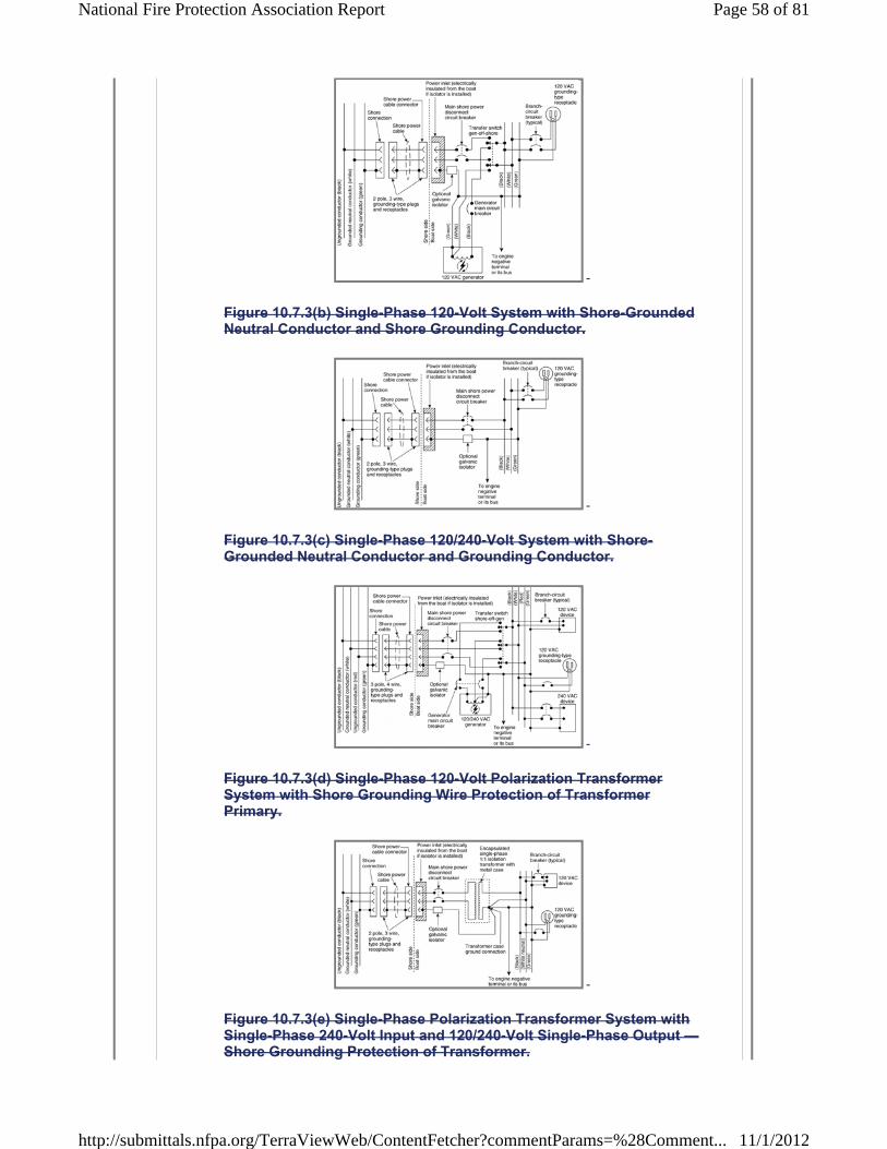
Figure 10.7.3(b) Single-Phase 120-Volt System with Shore-Grounded Neutral Conductor and Shore Grounding Conductor.
Figure 10.7.3(c) Single-Phase 120/240-Volt System with Shore-Grounded Neutral Conductor and Grounding Conductor.
Figure 10.7.3(d) Single-Phase 120-Volt Polarization Transformer System with Shore Grounding Wire Protection of Transformer Primary.
Figure 10.7.3(e) Single-Phase Polarization Transformer System with Single-Phase 240-Volt Input and 120/240-Volt Single-Phase Output —Shore Grounding Protection of Transformer.
Page 58 of 81National Fire Protection Association Report
11/1/2012http://submittals.nfpa.org/TerraViewWeb/ContentFetcher?commentParams=%28Comment...
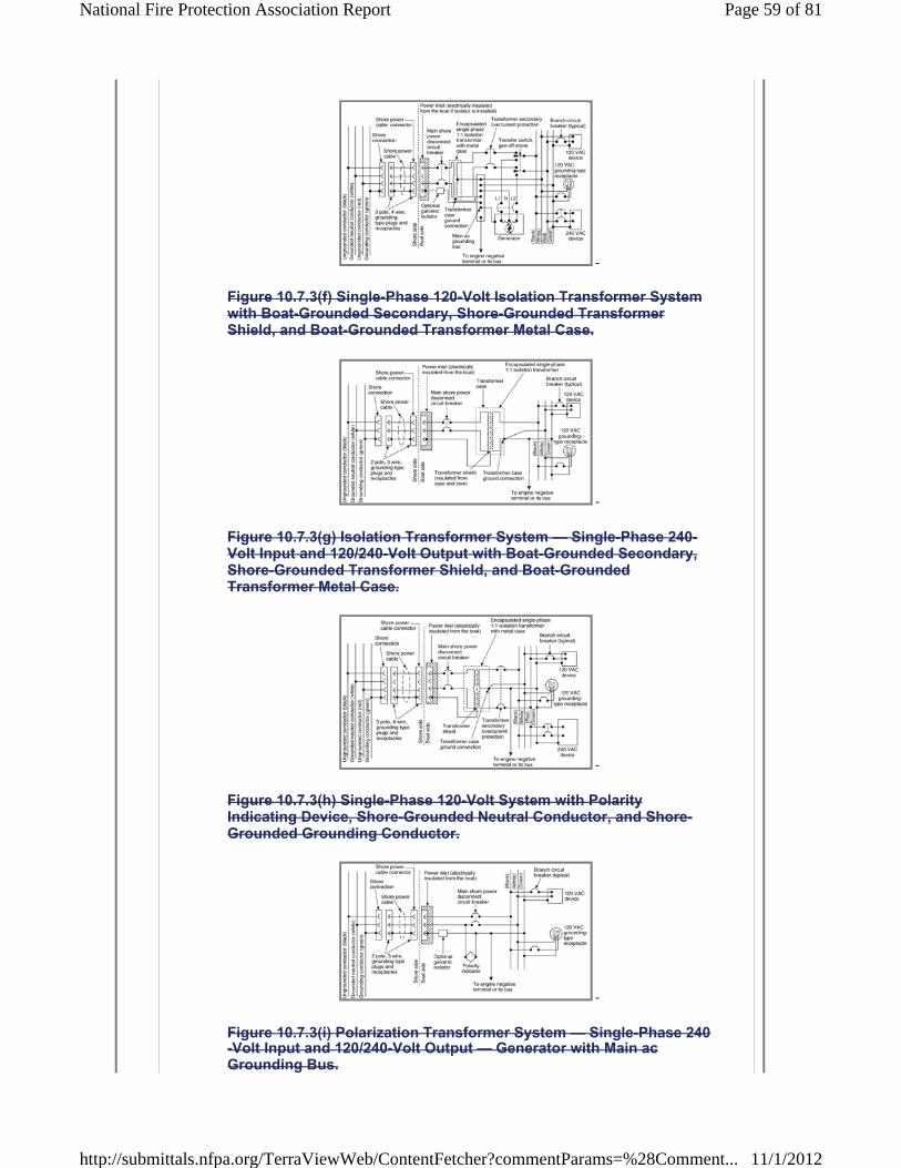
Figure 10.7.3(f) Single-Phase 120-Volt Isolation Transformer System with Boat-Grounded Secondary, Shore-Grounded Transformer Shield, and Boat-Grounded Transformer Metal Case.
Figure 10.7.3(g) Isolation Transformer System — Single-Phase 240-Volt Input and 120/240-Volt Output with Boat-Grounded Secondary, Shore-Grounded Transformer Shield, and Boat-Grounded Transformer Metal Case.
Figure 10.7.3(h) Single-Phase 120-Volt System with Polarity Indicating Device, Shore-Grounded Neutral Conductor, and Shore-Grounded Grounding Conductor.
Figure 10.7.3(i) Polarization Transformer System — Single-Phase 240-Volt Input and 120/240-Volt Output — Generator with Main ac Grounding Bus.
Page 59 of 81National Fire Protection Association Report
11/1/2012http://submittals.nfpa.org/TerraViewWeb/ContentFetcher?commentParams=%28Comment...

10.8 Overcurrent Protection. 10.8.1 Rating of Overcurrent Protection Devices. 10.8.1.1 Overcurrent protection devices shall have a temperature rating and demand load characteristics consistent with the protected circuit and their location in the boat (e.g., in a machinery space).10.8.1.2 The rating of the overcurrent protection device shall not exceed the maximum current-carrying capacity of the conductor being protected.10.8.2 Circuit Breakers.
The following shall apply to circuit breakers:
(1) They shall have an ac voltage rating of not less than the nominal system voltage.
(2) They shall be of the trip-free type.
(3) They shall be capable of an interrupting capacity in accordance with Table 10.8.2 .
(4)
Table 10.8.2 Circuit-Breaker Interrupting Capacity (Amperes)
Notes:
(8)
(5) ANSI/UL 489, Standard for Safety Molded-Case Circuit Breakers and Circuit-Breaker Enclosures
(6) ANSI/UL 1077, Standard for Safety Supplementary Protectors for Use in Electrical Equipment , if used as a branch circuit breaker and able to interrupt the current specified for branch circuit breakers in Table 10.8.2 alone or in combination with the main circuit breaker
(7) UL 1133, Standard for Safety Boat Circuit Breakers
* They shall meet the marine requirements of one of the following:
* If located in a space that requires ignition protection, they shall meet the requirements of UL 1500, Standard for Safety Ignition-Protection Test for Marine Products , at four times their rated current.
Main Shore Power Shore Power Source Disconnect Circuit Breaker Branch Breaker 120V–30A 3000 3000 120V–50A 3000 3000 120/240V–50A 5000 3000 240V–50 A 5000 3000 120/208V–3-phase/wye 30A 5000 3000 120/240V–100A 5000 3000 120/208V–3-phase/wye 100A 5000 3000
Page 60 of 81National Fire Protection Association Report
11/1/2012http://submittals.nfpa.org/TerraViewWeb/ContentFetcher?commentParams=%28Comment...

(1) The main circuit breaker shall be considered the first circuit breaker(s) connected to a source of ac power. All subsequent breakers, including submain breakers connected in series with a main circuit breaker, are considered to be branch circuit breakers.
(2) A fuse in series with, and ahead of, a circuit breaker shall be permitted to be required by the circuit-breaker manufacturer to achieve the interrupting capacity specified in Table 10.8.2.
10.8.3 Fuses. Fuses shall comply with the following:
(1) They shall have an ac voltage rating of not less than the nominal system voltage.
(2) They shall be capable of an interrupting capacity in accordance with Table 10.8.2 .
(3)
(4) They shall meet the requirements of the applicable part of ANSI/UL 248, Low Voltage Fuses, as dictated by the fuse class.
10.8.4 Fuse Holders. Fuse holders shall meet the requirements of ANSI/UL 512, Standard for Safety Fuseholders , for the class of fuse being used.10.9 Main Supply. 10.9.1 Common-trip circuit breakers shall be provided in main supply conductors as follows:
(1) 120-volt ac, single-phase — ungrounded and grounded conductors (white)
(2) 240-volt ac, single-phase — both ungrounded conductors
(3) 120/240-volt ac, single-phase — both ungrounded conductors
(4) 120/240-volt ac, delta three-phase — all ungrounded conductors
(5) 120/208-volt ac, wye three-phase — all ungrounded conductors
10.9.2 Supply Feeders Exceeding 10 ft (3 m). 10.9.2.1 *If the location of the main feeder supply disconnect circuit breaker is in excess of 10 ft (3 m) from the shore power inlet or the electrical attachment point of a permanently installed shore power cord, additional fuses or circuit breakers shall be provided within 10 ft (3 m) of the inlet or attachment point to the electrical system of the boat.10.9.2.2
* If located in a space that requires ignition protection, they shall meet the requirements of SAE J1171, External Ignition Protection for Marine Devices , or UL 1500, Standard for Safety Ignition-Protection Test for Marine Products ; and if an internal explosion test is required, the test shall be conducted at no less than 4 times the current rating of the fuse.
Page 61 of 81National Fire Protection Association Report
11/1/2012http://submittals.nfpa.org/TerraViewWeb/ContentFetcher?commentParams=%28Comment...

If additional fuses are required by 10.9.2.1 , their rating shall be such that circuit breakers trip before the fuses open the circuit in the event of overload.10.9.2.3 If additional fuses are required by 10.9.2.1 , the ampere rating of the additional fuses or circuit breaker shall not exceed 125 percent of the rating of the main shore power disconnect circuit breaker.10.9.3 * Overcurrent Protection Location. Conductors shall be provided with overcurrent protection at the source of power unless permitted by 10.9.3.1 , 10.9.3.2 , or 10.9.3.3 .10.9.3.1 Where not practical to locate overcurrent protection at the source of power, conductors shall be provided with overcurrent protection no more than 7 in. (18 cm) from the point at which the conductor is connected to the source of power measured along the conductor.10.9.3.2 If the conductor is contained in a sheath or enclosure, such as a junction box, control box, or enclosed panel, throughout the required distance, and where not practical to locate overcurrent protection at the source of power, conductors shall be provided with overcurrent protection no more than 40 in. (102 cm) from the point at which the conductor is connected to the source of power.10.9.3.3 If the conductor is connected directly to the battery terminal, and where not practical to locate overcurrent protection at the source of power, conductors shall be provided with overcurrent protection no more than 72 in. (183 cm) from the battery terminal.10.9.4 Self-limiting generators, whose maximum overload current does not exceed 120 percent of its rated current output, shall not be required to have external overcurrent protection.10.10 Branch Circuits. 10.10.1 Ungrounded Conductor. 10.10.1.1 Each ungrounded conductor of a branch circuit shall be provided with overcurrent protection at the point of connection to the panelboard bus.10.10.1.2 Each circuit breaker or fuse required by 10.10.1.1 shall not be rated in excess of the current rating of the smallest conductor between the fuse or circuit breaker and the load.10.10.2 In branch circuits, circuit breakers and switches shall open all grounded and ungrounded conductors simultaneously except for the following conductors:
(1) A polarized circuit with a polarity indicator
(2) The neutral leg of a grounded secondary of a polarization or isolation transformer
10.10.3 Fuses shall not be used in the grounded conductor.10.10.4
Page 62 of 81National Fire Protection Association Report
11/1/2012http://submittals.nfpa.org/TerraViewWeb/ContentFetcher?commentParams=%28Comment...
If circuits contain two or more ungrounded current-carrying conductors that are protected by fuses, means shall be provided to disconnect all energized legs of the circuit simultaneously or to remove all fuses from the circuit simultaneously.10.10.5 All ac branch-circuit conductors to receptacles or equipment, other than those contained completely within equipment or enclosures, shall be of the jacketed type.10.10.6 Alternating Current (ac) Motors. 10.10.6.1 Each motor or motor-operated device shall be individually protected by an overcurrent protection device unless the motor will not overheat under locked rotor conditions.10.10.6.2 The overcurrent protection device shall not be rated at more than 125 percent of the motor full-load current rating.10.10.6.3 The overcurrent protection device shall be permitted to be integral and of an automatic resetting type.10.10.7 Battery Chargers and Inverters. 10.10.7.1 Each ungrounded conductor to a battery charger shall be provided with overcurrent protection at the point of connection to the main switchboard or the distribution panel.10.10.7.2 Battery chargers, inverters, and inverter/chargers, and their installation shall comply with the requirements of ABYC A-31, Battery Chargers and Inverters .10.10.7.3 Each battery charger shall be fitted with a means of indicating the output current.10.11 Ground-Fault Circuit Interrupters (GFCIs). 10.11.1 A GFCI shall be permitted to be used on any single-phase ac circuit and shall be used for all receptacles in a head, a galley, or a machinery space or on a weather deck as required by 10.15.7 .10.11.2 GFCI breakers shall comply with the following:
(1) They shall meet the requirements of ANSI/UL 943, Standard for Safety Ground-Fault Circuit-Interrupters , and ANSI/UL 489, Standard for Safety Molded-Case Circuit Breakers and Circuit-Breaker Enclosures.
(2) They shall be permitted to be installed as panelboard feeder breakers to protect all associated circuits, or in individual branch circuits.
10.11.3 GFCI receptacle devices shall comply with the following:
(1) They shall meet the requirements of ANSI/UL 943, Standard for Safety Ground-Fault Circuit-Interrupters , and ANSI/UL 498, Standard for Safety Attachment Plugs and Receptacles.
Page 63 of 81National Fire Protection Association Report
11/1/2012http://submittals.nfpa.org/TerraViewWeb/ContentFetcher?commentParams=%28Comment...
(2) They shall be permitted to be installed as part of a convenience outlet installation, either in single outlet applications or in multiple “feed-through” installations.
10.11.4 *GFP circuit breakers shall be permitted to be installed as the main breaker on the primary side of isolation transformers.10.12 Appliances and Equipment. 10.12.1 Appliances and fixed ac electrical equipment used on boats shall be designed so that the current-carrying parts of the device are insulated effectively from all exposed electrically conductive parts.10.12.2 All exposed electrically conductive non-current-carrying parts of fixed ac electrical equipment and appliances intended to be grounded shall be connected to the grounding system.10.12.3 If an appliance has a neutral-to-ground bonding strap, the bonding strap shall be removed.10.13 Conductors and Flexible Cords. 10.13.1 Conductors shall have a minimum rating of 600 volts.10.13.2 Flexible cords shall have a minimum rating of 300 volts.10.13.3 Conductors shall be selected from the types specified in Table 9.12.3(b) .10.13.4 Flexible cords shall be selected from the types specified in Table 9.12.4 .10.13.5
Conductors and flexible cords shall be of stranded copper with circular mil area and stranding in accordance with Table 10.13.5 .
Table 10.13.5 Conductor Circular Mil (CM) Area and Stranding
Note: Metric wire sizes can be used if of equivalent circular mil area. If the circular mil area of the metric conductor is less than that listed, the wire ampacity needs to be corrected based on the ratio of the circular mil areas.
a To recognize stranded conductors made of AWG elements, note that the actual nominal CM area can differ from the specified nominal CM area but by no more than 7 percent. The circular mil area is equal to the mathematical square of the specified diameter of the AWG stranded solid copper conductor measured in one-thousandths of an inch, as shown in the following equation:
Conductor Size
(AWG) Nominal
CM Area a Minimum
Number of Strands Type 2 b Type 3 c 18 1,620 16 —16 2,580 19 26 14 4,110 19 41 12 6,530 19 65 10 10,380 19 105 8 16,510 19 168 6 26,240 37 266 4 41,
Page 64 of 81National Fire Protection Association Report
11/1/2012http://submittals.nfpa.org/TerraViewWeb/ContentFetcher?commentParams=%28Comment...

b Conductors with Type 2 stranding shall be permitted to be used for wiring that is subject to movement from vibration or minor flexing. If four or more conductors are run in a cable, Type 2 stranding shall be permitted to be used for frequent flexing applications.
c Conductors with Type 3 stranding shall be used for any wiring where frequent flexing is involved in normal use.
10.13.6
Conductor sizes, as determined by Table 10.13.5 , shall not carry current greater than that indicated in Table 10.13.6(a) , based on the temperature rating of the wire, and the following derating factors:
(1) Conductors used in or routed through an engine space shall be corrected in accordance with Table 10.13.6(b) .
(2) Current-carrying conductors that are bundled shall be derated in accordance with Table 10.13.6(c) .
Table 10.13.6(a) Ampacities of Insulated Conductors
Table 10.13.6(b) Engine Room Temperature Derating Factor
Table 10.13.6(c) Current-Carrying Conductor Bundling Derating Factor
10.13.7 Conductors, other than those contained completely within equipment or enclosures, shall be at least No. 16 AWG.10.13.8
Temperature Rating of Conductor Insulation Conductor Size (AWG) 60°C
(140°F) 75°C
(167°F) 80°C
(176°F) 90°C
(194°F) 105°C
(221°F) 125°C
(257°F) 200°C
(392°F)18 10 10 15 20 20 25 25 16 15 15 20 25 25 30 35 14 20 20 25 30 35 40 45 12 25 25 35 40 45 50 55 10 40
60°C
(140°F) 75°C
(167°F) 80°C
(176°F) 90°C
(194°F) 105°C
(221°F) 125°C
(257°F) 220°C
(392°F) Temperature rating of conductor 0.58 0.75 0.78 0.82 0.85 0.89 1.00
Number of Energized Wires in a Bundle Correction Factor 3 0.70 4 to 6 0.60 7 to 24 0.50 25 and above 0.40
Page 65 of 81National Fire Protection Association Report
11/1/2012http://submittals.nfpa.org/TerraViewWeb/ContentFetcher?commentParams=%28Comment...

All conductors shall meet UL 1426, Standard for Safety Electrical Cables for Boats , and shall be so labeled.10.14 Installation. 10.14.1 All connections normally carrying current shall be made in enclosures with interior surfaces having a flame spread rating of not more than 25 as tested in accordance with NFPA 255, Standard Method of Test of Surface Burning Characteristics of Building Materials .10.14.2 All conductors, other than those contained completely within equipment or enclosures, shall be supported to relieve strain on connections.10.14.3 Where ac and dc conductors are run together, other than conductors contained completely within equipment or enclosures, the ac conductors shall be sheathed, bundled, or otherwise kept separate from the dc conductors.10.14.4 * Conductor Support. 10.14.4.1 Conductors shall be supported for their entire length unless permitted otherwise by 10.14.4.2 through 10.14.4.4 .10.14.4.2 Conductors shall be permitted to be supported at least every 18 in. (46 cm) by nonmetallic clamps of a size to hold the conductors firmly in place.10.14.4.2.1 Nonmetallic straps or clamps shall not be used over engine(s), moving shafts, other machinery, or passageways if failure can result in a hazardous condition.10.14.4.2.2 Conductor material shall be resistant to oil, gasoline, and water and shall not break or crack under flexing within a temperature range of -30°F to 250°F (-34°C to 121°C).10.14.4.3 Metal Straps with Insulating Material. 10.14.4.3.1 Conductors shall be permitted to be supported at least every 18 in. (46 cm) by metal straps or clamps with smooth, rounded edges to hold the conductors firmly in place without damage to the conductors or insulation.10.14.4.3.2 Sections of the conductor or cable located directly under the strap or clamp shall be protected by means of loom, tape, or other suitable wrapping to prevent injury to the conductor.10.14.4.4 Conductors shall be permitted to be supported at least every 18 in. (46 cm) by metal clamps lined with an insulating material resistant to the effects of oil, gasoline, and water.10.14.5 Junction boxes, cabinets, and other enclosures in which electrical connections are made shall be weatherproof or installed in a protected location to minimize the entrance or accumulation of moisture or water within the boxes, cabinets, or enclosures.10.14.6 In wet locations, metallic boxes, cabinets, or enclosures shall be mounted to minimize the entrapment of moisture between the box, cabinet, or enclosure and the adjacent structure.10.14.7
Page 66 of 81National Fire Protection Association Report
11/1/2012http://submittals.nfpa.org/TerraViewWeb/ContentFetcher?commentParams=%28Comment...

If an air space is used to achieve the requirement of 10.14.6 , the space
shall be no less than 1 ? 4 in. (6.4 mm).10.14.8 Unused openings in boxes, cabinets, and weatherproof enclosures shall be closed.10.14.9 *Current-carrying conductors shall be routed above the bilge water level and other areas where water can accumulate unless the wiring is of a submersible type, and connections shall be watertight.10.14.10 *Conductors shall be routed in accordance with the following criteria:
(1) Unless an equivalent thermal barrier is provided, there shall be a clearance of no less than 2 in. (5 cm) between conductors and water-cooled exhaust components.
(2) There shall be a clearance of no less than 9 in. (23 cm) between conductors and dry exhaust components where the conductor is not directly above the exhaust.
(3) Conductors shall not be routed directly above a dry exhaust.
10.14.11 Physical Damage. 10.14.11.1 Conductors subject to physical damage shall be protected by loom, conduit, tape, raceways, or other equivalent protection.10.14.11.2 The protection required by 10.14.11.1 shall be self-draining.10.14.11.3 Conductors passing through or around bulkheads or structural members shall be protected to minimize insulation damage such as chafing or compression.10.14.11.4 Conductors also shall be routed clear of sources of chafing such as steering cable and linkages, engine shafts, and throttle connections.10.14.12 All permanently installed appliances and utilization equipment shall be mounted securely to the boat's structure.10.14.13 Wiring Connections. 10.14.13.1 Wiring connections shall be designed and installed to make mechanical and electrical joints without damage to the conductors.10.14.13.2 Metals. 10.14.13.2.1 Metals used for the terminal studs, nuts, and washers shall be corrosion resistant and galvanically compatible with the conductor and terminal lug.10.14.13.2.2 Aluminum and unplated steel shall not be used for studs, nuts, and washers.10.14.13.2.3
Page 67 of 81National Fire Protection Association Report
11/1/2012http://submittals.nfpa.org/TerraViewWeb/ContentFetcher?commentParams=%28Comment...

Each conductor splice joining conductor to conductor, conductor to connectors, and conductor to terminals shall be able to withstand a tensile force equal to at least the value shown in Table 9.14.3 for the smallest conductor size used in the splice for a 1-minute duration without breaking.10.14.13.3 Terminal Connectors. 10.14.13.3.1 Terminal connectors shall be of the ring or captive spade type unless permitted otherwise by 10.14.13.3.2 .10.14.13.3.2 Terminal connectors shall be permitted to be of the friction type where the following conditions are met:
(1) Circuit is rated at not more than 20 amperes or the manufacturer's rating if the terminal design meets the requirements of ANSI/UL 310, Standard for Electrical Quick-Connect Terminals , or ANSI/UL 1059, Standard for Terminal Blocks.
(2) Voltage drop from terminal to terminal does not exceed 50 millivolts for a 20-ampere current flow.
(3) Connection does not separate if subjected to a 6 lb (26.7 N) tensile force along the axial direction of the connector for 1 minute.
10.14.14 Set-Screw, Pressure-Type Connectors. 10.14.14.1 Connections shall be permitted to be made using a set-screw, pressure-type conductor connector.10.14.14.2 The connectors addressed in 10.14.14.1 shall be provided with a means to prevent the set screw from bearing directly on the conductor strands.10.14.15 Twist-on connectors (wire nuts) shall not be used.10.14.16 Solder shall not be the sole means of mechanical connection in any circuit unless the conductor is contained completely within equipment or enclosures.10.14.17 Solderless crimp-on connectors shall be attached with the type of crimping tools designed for the connector used.10.14.18 No more than four conductors shall be secured to any terminal stud.10.14.19 Two or more terminal studs shall be connected together by means of jumpers or copper straps where more than four conductors would be needed at a terminal stud.10.14.20 Terminal connectors of the ring and captive spade type shall be the same nominal size as the stud.10.14.21 Conductors terminating at panelboards in junction boxes or fixtures shall be arranged to provide a length of conductor to relieve tension, to allow for repairs, and to permit multiple conductors to be fanned at terminal studs.10.14.22
Page 68 of 81National Fire Protection Association Report
11/1/2012http://submittals.nfpa.org/TerraViewWeb/ContentFetcher?commentParams=%28Comment...

The shanks of terminals, other than those used in grounding systems, shall be protected against accidental shorting by the use of insulation barriers or sleeves.10.15 Receptacles. 10.15.1 Receptacles shall be installed in locations normally not subject to rain, spray, or flooding, or shall be protected as follows:
(1) Weatherproof if subject to rain or spray
(2) Watertight if subject to flooding
10.15.2 Receptacles shall be of the grounding type with a terminal provided for the grounding (green, or green with yellow stripe) conductor in accordance with ANSI/NEMA WD-6, Wiring Devices — Dimensional Requirements .10.15.3 Receptacles and matching plugs used on ac systems shall not be interchangeable with receptacles and matching plugs used on dc systems.10.15.4 Power wiring for receptacles shall be connected as follows:
(1) They shall be connected so that the grounded (white) conductor attaches to the terminal identified by a letter(s) or a light color (normally silver).
(2) They shall be connected so that the ungrounded conductor(s) shall be attached to the terminal identified by a letter(s) or a dark color (normally brass or copper).
10.15.5 A branch circuit supplying a combination of receptacle loads and permanently connected loads shall not supply fixed loads in excess of the following:
(1) 600 W for a 15-ampere circuit
(2) 1000 W for a 20-ampere circuit
10.15.6 Receptacles provided for the galley shall be located so that, when appliance cords are plugged in, they do not cross a traffic area, galley stove, or sink.10.15.7 *If installed in a head, a galley, or a machinery space or on a weather deck, the receptacle shall be protected by a Type A (nominal 5 milliamperes) GFCI.10.15.8
Page 69 of 81National Fire Protection Association Report
11/1/2012http://submittals.nfpa.org/TerraViewWeb/ContentFetcher?commentParams=%28Comment...

Electrical systems not equipped with polarity indicators using two-pole circuit breakers shall use a two-pole GFCI breaker in place of single-pole GFCI receptacles in the circuits that supply receptacles, unless the system employs polarization or isolation transformers that establish the polarity on the boat.10.16 Main Panelboard. 10.16.1 A main panelboard shall meet the following criteria:
(1) It shall be installed in a readily accessible location.
(2) It shall be weatherproof or protected from weather and splash.
10.16.2 A main panelboard shall be permitted to serve as a distribution center.10.16.3 Boats equipped with both ac and dc electrical systems shall have their distribution on separate panelboards or, in the case of systems with combined ac and dc panelboards, the panel shall be designed so that when the panel is open there is no access to energized ac parts without the use of tools.10.16.4 Panelboards shall be permanently marked with the system voltage value and either “VAC” or the system frequency (e.g., “120 VAC” or “120V-60 hertz”).10.16.5 If the frequency is other than 60 hertz, the frequency shall be indicated.10.16.6 For three-phase systems the following shall be indicated:
(1) System voltage
(2) Phase
(3) Number of conductors
10.16.7 Voltmeters. 10.16.7.1 A system voltmeter shall be installed for any of the following situations:
(1) System is designed to supply motor circuits.
(2) Onboard generator is installed.
(3) Inverter.
10.16.7.2 Where a voltmeter is required by 10.16.7.1 (3), the voltmeter shall be located on or in close proximity to the panelboard.10.17 Alternating-Current (ac) Generators. 10.17.1
Page 70 of 81National Fire Protection Association Report
11/1/2012http://submittals.nfpa.org/TerraViewWeb/ContentFetcher?commentParams=%28Comment...

Alternating-current generators shall be connected to the electrical distribution system through a selector switch in accordance with 10.2.8 and Figure 10.7.3(a) through Figure 10.7.3(i) .10.17.2 Power Feeders. 10.17.2.1 Power feeders from ac generators shall be sized to accommodate at least the generator's maximum rated output.10.17.2.2 The power feeder shall be protected at the generator with overcurrent protection devices in accordance with Section 10.8 unless the generator is a self-limiting generator having a maximum overload current of no more than 120 percent of the generator's rated current output.10.17.2.3 The rating of overcurrent protection devices required by 10.17.2.2 shall not exceed 120 percent of the generator's rated output.10.18 Isolation of Galvanic Currents. 10.18.1 Boats using an isolation transformer to reduce galvanic corrosion shall use an isolation transformer system in accordance with ABYC E-11, AC and DC Electrical Systems on Boats , and 10.20.4 or 10.20.7 .10.18.2 Boats using a galvanic isolator to reduce galvanic corrosion shall use a galvanic isolator in the grounding conductor in accordance with ABYC A-28, Galvanic Isolators .10.19 Shore Power. 10.19.1 Power Inlet. 10.19.1.1 The receptacle installed to receive a connecting cable to carry ac shore power aboard shall be a male-type connector.10.19.1.2 Power inlets shall comply with the following:
(1) Power inlets installed in locations subject to rain, spray, or splash shall be weatherproof, whether or not in use.
(2) Power inlets installed in areas subject to flooding or momentary submersion shall be watertight, whether or not in use.
(3) A warning label shall be located alongside each shore power inlet location on the boat. (See 10.3.1 .)
(4) If a boat uses an isolation transformer or an isolator to prevent galvanic current flow through the grounding conductor, the metallic shell of the shore power inlet shall be insulated from metallic surfaces or any contact with a boat ground. [See Figure 10.7.3(d) through Figure 10.7.3(f) .]
10.19.2 Shore Power Cable. Boats with an ac electrical system(s) intended to use shore power provided in accordance with NFPA 70 , National Electrical Code , Article 555, and NFPA 303, Fire Protection Standard for Marinas and Boatyards , shall be provided with a shore power cable that complies with the following criteria:
Page 71 of 81National Fire Protection Association Report
11/1/2012http://submittals.nfpa.org/TerraViewWeb/ContentFetcher?commentParams=%28Comment...
(1) A male locking and grounding-type connection that conforms with NFPA 70 , National Electrical Code , Article 555, and ANSI/NEMA WD-6, Wiring Devices — Dimensional Requirements , if a configuration for that service exists in ANSI/NEMA WD-6
(2) A female boat connection of the locking and grounding type that conforms with ANSI/NEMA WD-6, Wiring Devices — Dimensional Requirements , if a configuration for that service exists in ANSI/NEMA WD-6, unless the shore power cable is permanently connected to the boat and the boat end of the cable is terminated with a locking and grounding female type connector to match the boat power inlet
(3) A minimum length of 25 ft (7.6 m) and meets the marine requirements of ANSI/UL 817, Standard for Safety Cord Sets and Power-Supply Cords
10.19.3 Shore power inlet connections and the shore power cable terminals shall be inspected at a minimum semi-annually for evidence of alteration, damage, arcing, or overheating of the terminal connectors.10.19.3.1 Any evidence of alteration, damage, arcing, or overheating of the terminal connectors shall require renewal of the affected component.10.19.3.2 Any evidence of alteration, damage, arcing, or overheating of the terminal connectors shall require inspection of the shore power supply feeder(s) for damage to the insulation.10.19.3.3 Any evidence of alteration, damage, arcing, or overheating of the terminal connectors shall require the cause of the alteration, damage, arcing, or overheating to be determined and corrective action taken.10.20 Application of Types of Shore Power Circuits. 10.20.1 Single-Phase 120-Volt System with Shore-Grounded Neutral Conductor and Shore Grounding Conductor. 10.20.1.1 The system specified in 10.20.1 shall be permitted to be used on any nonmetallic hull boat with underwater hardware of metal alloys that are at least as galvanically noble as manganese bronze.10.20.1.2 The system specified in 10.20.1 shall be permitted to be used with metal hull boats if protection against galvanic corrosion is provided by means of a cathodic protection system or a galvanic isolator.10.20.1.3 The system shall be wired in accordance with the basic circuit shown in Figure 10.7.3(b) .10.20.2 Single-Phase 120/240-Volt System with Shore-Grounded Neutral Conductor and Shore Grounding Conductor. 10.20.2.1 The system specified in 10.20.2 shall be permitted to be used on any nonmetallic hull boat with underwater hardware of metal alloys that are at least as galvanically noble as manganese bronze.10.20.2.2
Page 72 of 81National Fire Protection Association Report
11/1/2012http://submittals.nfpa.org/TerraViewWeb/ContentFetcher?commentParams=%28Comment...
The system specified in 10.20.2 shall be permitted to be used with metal hull boats if protection against galvanic corrosion is provided by means of a cathodic protection system or a galvanic isolator.10.20.2.3 The system shall be wired in accordance with the basic circuit shown in Figure 10.7.3(c) .10.20.3 Single-Phase 120-Volt Primary and Secondary Isolation Transformer System. 10.20.3.1 With shore grounding protection of the transformer core, the system specified in 10.20.3 shall be permitted to be used with any metallic or nonmetallic hull boat.10.20.3.2 The system shall be wired in accordance with the basic circuit shown in Figure 10.7.3(d) .10.20.3.3 The grounded transformer core and the metallic shell of the shore power inlet shall be insulated from contact with any boat ground.10.20.3.4 The transformer secondary shall be grounded on the boat.10.20.4 Isolation Transformer with Single-Phase 240-Volt Input and 120/240-Volt Output with Shore Grounding Protection of Transformer Core. 10.20.4.1 The system specified in 10.20.4 shall be permitted to be used with any boat.10.20.4.2 The system specified in 10.20.4 shall be used on all metal hull boats if other means of protection against galvanic corrosion, such as a galvanic isolator, is not provided.10.20.4.3 The system shall be wired in accordance with the basic circuit shown in Figure 10.7.3(e) .10.20.4.4 The metallic shell of the shore power inlet shall be insulated from contact with any boat ground.10.20.4.5 The center leg of the transformer secondary shall be grounded on the boat, establishing a new neutral for the boat system.10.20.5 Single-Phase 120-Volt Primary and Secondary Polarization Transformer System with Shore-Grounded Neutral and Shore Grounding Protection of Transformer. 10.20.5.1 The system specified in 10.20.5 shall be permitted to be used on any nonmetallic hull boat with underwater hardware of metal alloys that are at least as galvanically noble as manganese bronze.10.20.5.2 The system specified in 10.20.5 shall be permitted to be used with metal hull boats if protection against galvanic corrosion is provided by means of a cathodic protection system or a galvanic isolator.10.20.5.3 The system shall be wired in accordance with the basic circuit shown in Figure 10.7.3(f) .10.20.5.4
Page 73 of 81National Fire Protection Association Report
11/1/2012http://submittals.nfpa.org/TerraViewWeb/ContentFetcher?commentParams=%28Comment...

The transformer secondary shall be grounded on the boat.10.20.6 Single-Phase 120-Volt Primary and Secondary Polarization Transformer System with Shore-Grounded Neutral and GFCI Protection of Transformer Primary. 10.20.6.1 The system specified in 10.20.6 shall be permitted to be used with any metallic or nonmetallic hull boat.10.20.6.2 The system shall be wired in accordance with the basic circuit shown in Figure 10.7.3(f) .10.20.6.3 The metallic shell of the shore power inlet shall be insulated from contact with any boat ground.10.20.6.4 The transformer secondary shall be grounded on the boat.10.20.7 Single-Phase Isolation Transformer with 240-Volt Input and 120/240-Volt Secondary with GFCI Protection of Transformer Primary. 10.20.7.1 The system specified in 10.20.7 shall be permitted to be used with any metallic or nonmetallic hull boat.10.20.7.2 The system shall be wired in accordance with the basic circuit shown in Figure 10.7.3(g) .10.20.7.3 The metallic shell of the shore power inlet shall be insulated from contact with any boat ground.10.20.7.4 The central leg of the transformer secondary shall be grounded on the boat, establishing a new neutral for the boat system.10.20.8 Single-Phase Polarization Transformer with 240-Volt Input and 120/240-Volt Secondary and Shore Grounding Conductor Protection of Transformer Core. 10.20.8.1 The system specified in 10.20.8 shall be permitted to be used on any nonmetallic hull boat with underwater hardware of metal alloys that are at least as galvanically noble as manganese bronze.10.20.8.2 The system specified in 10.20.8 shall be permitted to be used with metal hull boats if protection against galvanic corrosion is provided by means of a cathodic protection system or a galvanic isolator.10.20.8.3 The system shall be wired in accordance with the basic circuit shown in Figure 10.7.3(e) .10.20.8.4 The center leg of the transformer secondary shall be grounded on the boat, establishing a new neutral for the boat system.Alternating Current (ac) Electrical Systems on Boats shall comply with:
ABYC E-11 AC & DC Electrical systems on Boats,
ABYC A-28 Galvanic Isolators,
ABYC A-31 Battery Chargers and Inverters , and
ABYC A-32 Power Conversion Equipment .
Page 74 of 81National Fire Protection Association Report
11/1/2012http://submittals.nfpa.org/TerraViewWeb/ContentFetcher?commentParams=%28Comment...

Statement of Problem and Substantiation for Public Input
This chapter is not comprehensive enough for complexity of recreational vessel electrical systems. Reference appropriate comprehensive industry standards which include important safety devices such as ELCI's
Submitter Information Verification
Submitter Full Name: BRIAN GOODWIN
Organization: AMERICAN BOAT & YACHT COUNCIL
Submittal Date: Fri Jun 22 10:11:13 EDT 2012
Committee Statement
Resolution: The Committee recognizes that vessels can be built to the standards and recommended practices of ABYC E-11 and that fire investigators use NFPA 302. The Committee considers the content of this chapter to be relevant to the scope of NFPA 302. Rather than strike the entire chapter the Committee requests the submitter to offer input that addresses the specific differences that exist between the two documents. A reference to ABYC E-11 has been added to Annex A. See FR-24.
Copyright Assignment
I, BRIAN GOODWIN, hereby irrevocably grant and assign to the National Fire Protection Association (NFPA) all and full rights in copyright in this Public Input (including both the Proposed Change and the Statement ofProblem and Substantiation). I understand and intend that I acquire no rights, including rights as a joint author, in any publication of the NFPA in which this Public Input in this or another similar or derivative form is used. I hereby warrant that I am the author of this Public Input and that I have full power and authority to enter into this copyright assignment.
By checking this box I affirm that I am BRIAN GOODWIN, and I agree to be legally bound by the above Copyright Assignment and the terms and conditions contained therein. I understand and intend that, by checking this box, I am creating an electronic signature that will, upon my submission of this form, have the same legal force and effect as a handwritten signature
Page 75 of 81National Fire Protection Association Report
11/1/2012http://submittals.nfpa.org/TerraViewWeb/ContentFetcher?commentParams=%28Comment...

Public Input No. 4-NFPA 302-2012 [ New Section after 10.19.2 ]
Shore power cable that has been tested by a recognized testing facility shall be acceptable.
Statement of Problem and Substantiation for Public Input
There has been a tremendous advance in the safety of shore power cable connectors that do not meet current NFPA 70 designs for shore power cables. We tried to address the issue of fires in these inlet connectors at the last re-write of NFPA 302 but there are still a significant number of boat fires resulting from the decades old terminal connections. The newer pin and plug smart plugs will prevent these fires.
Submitter Information Verification
Submitter Full Name: Kim MacCartney
Organization: Ace Recreational Marine Insura
Submittal Date: Wed May 02 08:15:29 EDT 2012
Committee Statement
Resolution: FR-27-NFPA 302-2012 The Committee revised the input submitted to conform with listed and labeled requirements for electrical equipment and devices found in NFPA 303.
Statement: There has been a tremendous advance in the safety of shore power cable connectors that do not meet current NFPA 70 designs for shore power cables. We tried to address the issue of fires in these inlet connectors at the last re-write of NFPA 302 but there are still a significant number of boat fires resulting from the decades old terminal connections. The newer pin and plug smart plugs will prevent these fires.
Copyright Assignment
I, Kim MacCartney, hereby irrevocably grant and assign to the National Fire Protection Association (NFPA) all and full rights in copyright in this Public Input (including both the Proposed Change and the Statement ofProblem and Substantiation). I understand and intend that I acquire no rights, including rights as a joint author, in any publication of the NFPA in which this Public Input in this or another similar or derivative form is used. I hereby warrant that I am the author of this Public Input and that I have full power and authority to enter into this copyright assignment.
By checking this box I affirm that I am Kim MacCartney, and I agree to be legally bound by the above Copyright Assignment and the terms and conditions contained therein. I understand and intend that, by checking this box, I am creating an electronic signature that will, upon my submission of this form, have the same legal force and effect as a handwritten signature
Page 76 of 81National Fire Protection Association Report
11/1/2012http://submittals.nfpa.org/TerraViewWeb/ContentFetcher?commentParams=%28Comment...
Public Input No. 26-NFPA 302-2012 [ New Section after 10.20.8.4 ]
Add a new section to read: An Equipment Leakage Circuit Interrupter (ELCI) or a Residual Current Device (RCD) shall be installed with or in addtiion to the main shore power disconnect circut breaker(s) aboard the vessel. The device trip level shall be a maximum of 30mA and the trip time shall be a maximum of 100mS. The device shall be readily accessible.
Statement of Problem and Substantiation for Public Input
There have been a number of fatal Electric Shock Drowning incidents that are caused by AC faults aboard boats. A Coast Guard study has investigated these incidents and states that these ELCI/RCD devices will reduce the causes of ESD.
Submitter Information Verification
Submitter Full Name: John McDevitt
Organization: [ Not Specified ]
Submittal Date: Mon Jul 30 09:37:16 EDT 2012
Committee Statement
Resolution: FR-26-NFPA 302-2012 The Committee changed the requirement to mandate the use of ground fault protection equipment that shall be installed in the mainshore power conductors to address the risk of fire within the scope of NFPA 302. The requirement was divided in accordance with the NFPA Manual of Style, July 2004.
Statement: There have been a number of fatal Electric Shock Drowning incidents that are caused by AC faults aboard boats. A Coast Guard study has investigated these incidents and states that these ELCI/RCD devices will reduce the causes of ESD.
Copyright Assignment
I, John McDevitt, hereby irrevocably grant and assign to the National Fire Protection Association (NFPA) all and full rights in copyright in this Public Input (including both the Proposed Change and the Statement of Problem and Substantiation). I understand and intend that I acquire no rights, including rights as a joint author, in any publication of the NFPA in which this Public Input in this or another similar or derivative form is used. Except to the extent that I may lack authority to make an assignment of content identified above, I hereby warrant that I am the author of this Public Input and that I have full power and authority to enter into this copyrightassignment.
By checking this box I affirm that I am John McDevitt, and I agree to be legally bound by the above Copyright Assignment and the terms and conditions contained therein. I understand and intend that, by checking this box, I am creating an electronic signature that will, upon my submission of this form, have the same legal force and effect as a handwritten signature
Origin (from sources other than the submitter)
USCG Study for Stray AC Current. ABYC - American Boat and Yacht Council
Page 77 of 81National Fire Protection Association Report
11/1/2012http://submittals.nfpa.org/TerraViewWeb/ContentFetcher?commentParams=%28Comment...

Public Input No. 27-NFPA 302-2012 [ New Section after 12.1.3 ]
Add a new section to read: Fixed fire extinguishing systems must be installed as high as practical in the engine space and as far from natural and mechanical ventilation as possible. Fixed fire extinguishing systems should be installed according to the extinguisher manufacturer's instructions.
Statement of Problem and Substantiation for Public Input
There have been failed or delayed activation incidents when the sensing component has been installed improperly. Specifically too close to natural or mechanical ventilation as well as too remote for effective coverage.
Submitter Information Verification
Submitter Full Name: John McDevitt
Organization: [ Not Specified ]
Submittal Date: Mon Jul 30 09:40:09 EDT 2012
Committee Statement
Resolution: See FR 30.
Copyright Assignment
I, John McDevitt, hereby irrevocably grant and assign to the National Fire Protection Association (NFPA) all and full rights in copyright in this Public Input (including both the Proposed Change and the Statement of Problem and Substantiation). I understand and intend that I acquire no rights, including rights as a joint author, in any publication of the NFPA in which this Public Input in this or another similar or derivative form is used. I hereby warrant that I am the author of this Public Input and that I have full power and authority to enter into this copyright assignment.
By checking this box I affirm that I am John McDevitt, and I agree to be legally bound by the above Copyright Assignment and the terms and conditions contained therein. I understand and intend that, by checking this box, I am creating an electronic signature that will, upon my submission of this form, have the same legal force and effect as a handwritten signature
Page 78 of 81National Fire Protection Association Report
11/1/2012http://submittals.nfpa.org/TerraViewWeb/ContentFetcher?commentParams=%28Comment...

Public Input No. 8-NFPA 302-2012 [ Chapter 13 ]
Chapter 13 Carbon Monoxide Detection 13.1* Carbon Monoxide and Smoke Detection Systems. A carbon monoxide detection system shall be installed on all boats with an enclosed accommodation compartment(s) and a gasoline generator set, or an inboard gasoline propulsion engine.13.2 Installation. Carbon monoxide detection systems and installation shall meet the requirements of ABYC A-24, Carbon Monoxide Detection Systems.
13.3 Smoke Detection. Move 12.2 to this section.
Statement of Problem and Substantiation for Public Input
I do not believe the requirement for smoke detectors should in a section labeled "Fire Protection Equipment" as the detector does not protect against fire, it only alerts to the presence of a fire. A smoke detector belongs in the same section as a carbon monoxide detector.
Submitter Information Verification
Submitter Full Name: Kim MacCartney
Organization: Ace Recreational Marine Insura
Submittal Date: Thu May 17 08:25:52 EDT 2012
Committee Statement
Resolution: The revisions recommended in this public input have been incorporated in FR 33, FR 35 and FR 36.
Copyright Assignment
I, Kim MacCartney, hereby irrevocably grant and assign to the National Fire Protection Association (NFPA) all and full rights in copyright in this Public Input (including both the Proposed Change and the Statement of Problem and Substantiation). I understand and intend that I acquire no rights, including rights as a joint author, in any publication of the NFPA in which this Public Input in this or another similar or derivative form is used. I hereby warrant that I am the author of this Public Input and that I have full power and authority to enter into this copyright assignment.
By checking this box I affirm that I am Kim MacCartney, and I agree to be legally bound by the above Copyright Assignment and the terms and conditions contained therein. I understand and intend that, by checking this box, I am creating an electronic signature that will, upon my submission of this form, have the same legal force and effect as a handwritten signature
Page 79 of 81National Fire Protection Association Report
11/1/2012http://submittals.nfpa.org/TerraViewWeb/ContentFetcher?commentParams=%28Comment...

Public Input No. 25-NFPA 302-2012 [ Section No. F.1.2.1 ]
F.1.2.1 ABYC Publications. American Boat & Yacht Council, Inc., 613 Third Street, Suite 10, Annapolis, MD 21403.
ABYC A-4, Fire Fighting Equipment, 2002 2008 .
ABYC TH-22, Educational Information About Carbon Monoxide, 2002 2012 .
ABYC TH-23, Design, Construction, and Testing of Boats in Consideration of Carbon Monoxide, 2004 2012 .
Add other ABYC reference documents with most recent publication dates.
Statement of Problem and Substantiation for Public Input
update to most current publication. Add missing referenced documents.
Submitter Information Verification
Submitter Full Name: BRIAN GOODWIN
Organization: AMERICAN BOAT & YACHT COUNCIL
Submittal Date: Fri Jun 22 10:40:43 EDT 2012
Committee Statement
Resolution: FR-38-NFPA 302-2012 The Committee added a reference to ABYC E-11.
Statement: The Committee has updated the referenced standards to most recent edition and added missing referenced documents as indicated.
Copyright Assignment
I, BRIAN GOODWIN, hereby irrevocably grant and assign to the National Fire Protection Association (NFPA) all and full rights in copyright in this Public Input (including both the Proposed Change and the Statement ofProblem and Substantiation). I understand and intend that I acquire no rights, including rights as a joint author, in any publication of the NFPA in which this Public Input in this or another similar or derivative form is used. I hereby warrant that I am the author of this Public Input and that I have full power and authority to enter into this copyright assignment.
By checking this box I affirm that I am BRIAN GOODWIN, and I agree to be legally bound by the above Copyright Assignment and the terms and conditions contained therein. I understand and intend that, by checking this box, I am creating an electronic signature that will, upon my submission of this form, have the same legal force and effect as a handwritten signature
Page 80 of 81National Fire Protection Association Report
11/1/2012http://submittals.nfpa.org/TerraViewWeb/ContentFetcher?commentParams=%28Comment...
Public Input No. 2-NFPA 302-2012 [ Section No. F.1.2.5 ]
F.1.2.5 UL Publications. Underwriters Laboratories Inc., 333 Pfingsten Road, Northbrook, IL 60062-2096.
ANSI/UL 217, Standard for Single and Multiple Station Smoke Alarms, 2006, Revised May 2007 2011 .
ANSI/UL 268, Smoke Detectors for Fire Protective Signaling Systems, 2006 2009 .
ANSI/UL 1971, Signaling Devices for Hearing Impaired, 2002, Revised May 2006 2008 .
Statement of Problem and Substantiation for Public Input
Update referenced standards to most recent edition as indicated.
Submitter Information Verification
Submitter Full Name: John Bender
Organization: Underwriters Laboratories Inc.
Submittal Date: Thu Apr 19 09:33:07 EDT 2012
Committee Statement
Resolution: FR-45-NFPA 302-2012
Statement: The Committee has updated the referenced standards to most recent edition as indicated.
Copyright Assignment
I, John Bender, hereby irrevocably grant and assign to the National Fire Protection Association (NFPA) all and full rights in copyright in this Public Input (including both the Proposed Change and the Statement of Problem and Substantiation). I understand and intend that I acquire no rights, including rights as a joint author, in any publication of the NFPA in which this Public Input in this or another similar or derivative form is used. I hereby warrant that I am the author of this Public Input and that I have full power and authority to enter into this copyright assignment.
By checking this box I affirm that I am John Bender, and I agree to be legally bound by the above Copyright Assignment and the terms and conditions contained therein. I understand and intend that, by checking this box, I am creating an electronic signature that will, upon my submission of this form, have the same legal force and effect as a handwritten signature
Page 81 of 81National Fire Protection Association Report
11/1/2012http://submittals.nfpa.org/TerraViewWeb/ContentFetcher?commentParams=%28Comment...

NFPA 302 – FIRST REVISIONS REPORT
PLEASE NOTE THIS REPORT WAS RE-CREATED AS PREVIOUSLY
THERE WAS ONLY A LINK TO THE FIRST REVISIONS. THE
CONTEXT OF THE MATERIAL HAS NOT CHANGED.
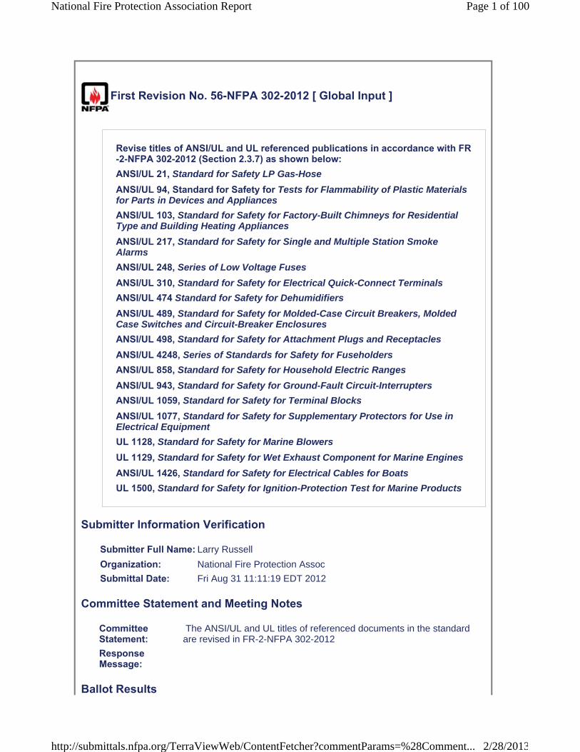
First Revision No. 56-NFPA 302-2012 [ Global Input ]
Revise titles of ANSI/UL and UL referenced publications in accordance with FR-2-NFPA 302-2012 (Section 2.3.7) as shown below:ANSI/UL 21, Standard for Safety LP Gas-Hose
ANSI/UL 94, Standard for Safety for Tests for Flammability of Plastic Materials for Parts in Devices and Appliances
ANSI/UL 103, Standard for Safety for Factory-Built Chimneys for Residential Type and Building Heating Appliances
ANSI/UL 217, Standard for Safety for Single and Multiple Station Smoke Alarms
ANSI/UL 248, Series of Low Voltage Fuses
ANSI/UL 310, Standard for Safety for Electrical Quick-Connect Terminals
ANSI/UL 474 Standard for Safety for Dehumidifiers
ANSI/UL 489, Standard for Safety for Molded-Case Circuit Breakers, Molded Case Switches and Circuit-Breaker Enclosures
ANSI/UL 498, Standard for Safety for Attachment Plugs and Receptacles
ANSI/UL 4248, Series of Standards for Safety for Fuseholders
ANSI/UL 858, Standard for Safety for Household Electric Ranges
ANSI/UL 943, Standard for Safety for Ground-Fault Circuit-Interrupters
ANSI/UL 1059, Standard for Safety for Terminal Blocks
ANSI/UL 1077, Standard for Safety for Supplementary Protectors for Use in Electrical Equipment
UL 1128, Standard for Safety for Marine Blowers
UL 1129, Standard for Safety for Wet Exhaust Component for Marine Engines
ANSI/UL 1426, Standard for Safety for Electrical Cables for Boats
UL 1500, Standard for Safety for Ignition-Protection Test for Marine Products
Submitter Information Verification
Submitter Full Name: Larry Russell
Organization: National Fire Protection Assoc
Submittal Date: Fri Aug 31 11:11:19 EDT 2012
Committee Statement and Meeting Notes
CommitteeStatement:
The ANSI/UL and UL titles of referenced documents in the standard are revised in FR-2-NFPA 302-2012
Response Message:
Ballot Results
Page 1 of 100National Fire Protection Association Report
2/28/2013http://submittals.nfpa.org/TerraViewWeb/ContentFetcher?commentParams=%28Comment...

This item has passed ballot
24 Eligible Voters
5 Not Returned
18 Affirmative All
1 Affirmative with Comments
0 Negative with Comments
0 Abstention
Not ReturnedChiasson, RussellColavecchio, William A.Game, E. C. LeBlanc, David J.Montgomery, Larry
Affirmative All, , , , , , , , , , , , , , , , , ,
Affirmative with CommentAdey, John Affirm
Page 2 of 100National Fire Protection Association Report
2/28/2013http://submittals.nfpa.org/TerraViewWeb/ContentFetcher?commentParams=%28Comment...
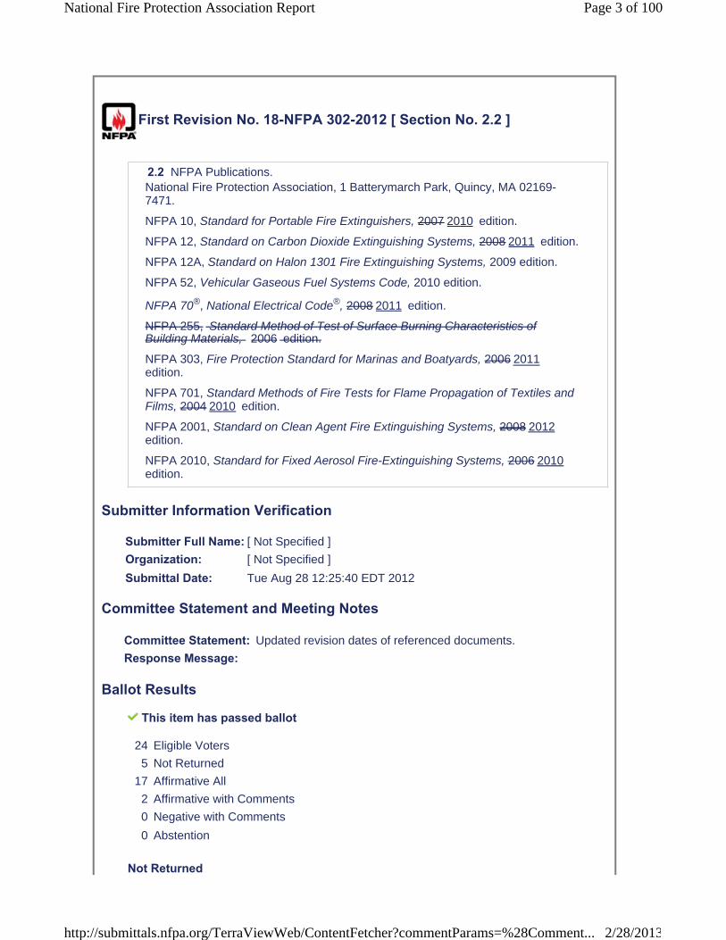
First Revision No. 18-NFPA 302-2012 [ Section No. 2.2 ]
2.2 NFPA Publications.National Fire Protection Association, 1 Batterymarch Park, Quincy, MA 02169-7471.
NFPA 10, Standard for Portable Fire Extinguishers, 2007 2010 edition.
NFPA 12, Standard on Carbon Dioxide Extinguishing Systems, 2008 2011 edition.
NFPA 12A, Standard on Halon 1301 Fire Extinguishing Systems, 2009 edition.
NFPA 52, Vehicular Gaseous Fuel Systems Code, 2010 edition.
NFPA 70®, National Electrical Code®, 2008 2011 edition.
NFPA 255, Standard Method of Test of Surface Burning Characteristics of Building Materials, 2006 edition.
NFPA 303, Fire Protection Standard for Marinas and Boatyards, 2006 2011edition.
NFPA 701, Standard Methods of Fire Tests for Flame Propagation of Textiles and Films, 2004 2010 edition.
NFPA 2001, Standard on Clean Agent Fire Extinguishing Systems, 2008 2012edition.
NFPA 2010, Standard for Fixed Aerosol Fire-Extinguishing Systems, 2006 2010edition.
Submitter Information Verification
Submitter Full Name: [ Not Specified ]
Organization: [ Not Specified ]
Submittal Date: Tue Aug 28 12:25:40 EDT 2012
Committee Statement and Meeting Notes
Committee Statement: Updated revision dates of referenced documents.
Response Message:
Ballot Results
This item has passed ballot
24 Eligible Voters
5 Not Returned
17 Affirmative All
2 Affirmative with Comments
0 Negative with Comments
0 Abstention
Not Returned
Page 3 of 100National Fire Protection Association Report
2/28/2013http://submittals.nfpa.org/TerraViewWeb/ContentFetcher?commentParams=%28Comment...

Chiasson, RussellColavecchio, William A.Game, E. C.LeBlanc, David J. Montgomery, Larry
Affirmative All, , , , , , , , , , , , , , , , ,
Affirmative with CommentAdey, John AffirmMcFarlin, David McFarlin Although voting affirmative, I think more study needs to be done relative to the new edition standards and how they may have an affect on 302.
Page 4 of 100National Fire Protection Association Report
2/28/2013http://submittals.nfpa.org/TerraViewWeb/ContentFetcher?commentParams=%28Comment...

First Revision No. 4-NFPA 302-2012 [ Section No. 2.3.1 ]
2.3.1 ABYC Publications.American Boat & Yacht Council, Inc., 613 Third Street, Suite 10, Annapolis, MD 21403.
ABYC A-24, Carbon Monoxide Detection Systems, 2007.
ABYC A-28, Galvanic Isolators, July 2004 2008 .
ABYC A-31, Battery Chargers and Inverters, 2007 2010 .
ABYC E-11, AC and DC Electrical Systems on Boats, 2008 2012 .
ABYC TE-4, Lighting Protection , 2006.
ABYC TH-23, Design, Construction, and Testing of Boats in Consideration of Carbon Monoxide, 2004 2012 .
Submitter Information Verification
Submitter Full Name: [ Not Specified ]
Organization: [ Not Specified ]
Submittal Date: Tue Aug 28 11:05:47 EDT 2012
Committee Statement and Meeting Notes
CommitteeStatement:
Committee has updated referenced publications with the current revision date. ABYC TE-4 has been added to the list since it is referenced in 3.3.5 and 11.1 of the standard.
Response Message:
Ballot Results
This item has passed ballot
24 Eligible Voters
5 Not Returned
17 Affirmative All
2 Affirmative with Comments
0 Negative with Comments
0 Abstention
Not ReturnedChiasson, RussellColavecchio, William A. Game, E. C.LeBlanc, David J. Montgomery, Larry
Page 5 of 100National Fire Protection Association Report
2/28/2013http://submittals.nfpa.org/TerraViewWeb/ContentFetcher?commentParams=%28Comment...
Affirmative All, , , , , , , , , , , , , , , , ,
Affirmative with CommentAdey, John AffirmMcFarlin, David McFarlin Although voting affirmative, I think more study needs to be done relative to the new edition standards and how they may have an affect on 302.
Page 6 of 100National Fire Protection Association Report
2/28/2013http://submittals.nfpa.org/TerraViewWeb/ContentFetcher?commentParams=%28Comment...
First Revision No. 13-NFPA 302-2012 [ Section No. 2.3.2 ]
2.3.2 AMCA Publication.Air Movement and Control Association, 30 West University Drive, Arlington Heights, IL 60004-1893.
AMCA/ANSI 210, Laboratory Methods of Testing Fans for Certified Aerodynamic Performance Rating, 1999 2007 .
Submitter Information Verification
Submitter Full Name: [ Not Specified ]
Organization: [ Not Specified ]
Submittal Date: Tue Aug 28 12:04:11 EDT 2012
Committee Statement and Meeting Notes
Committee Statement: Committee updated revision date and title of AMCA/ANSI 210.
Response Message:
Ballot Results
This item has passed ballot
24 Eligible Voters
5 Not Returned
16 Affirmative All
2 Affirmative with Comments
1 Negative with Comments
0 Abstention
Not ReturnedChiasson, RussellColavecchio, William A. Game, E. C.LeBlanc, David J. Montgomery, Larry
Affirmative All, , , , , , , ,
Page 7 of 100National Fire Protection Association Report
2/28/2013http://submittals.nfpa.org/TerraViewWeb/ContentFetcher?commentParams=%28Comment...

, , , , , , , ,
Affirmative with CommentAdey, John AffirmMcFarlin, David Although voting affirmative, I think more study needs to be done relative to the newedition standards and how they may have an affect on 302.
Negative with CommentWeinbrecht, Kenneth J. I hope I'm doing this right.....Are we removing Smoke Detectors from the standard? If we are....I object!
Page 8 of 100National Fire Protection Association Report
2/28/2013http://submittals.nfpa.org/TerraViewWeb/ContentFetcher?commentParams=%28Comment...
First Revision No. 14-NFPA 302-2012 [ Section No. 2.3.3 ]
2.3.3 ANSI Publication.American National Standards Institute, 25 West 43rd Street, 4th Floor, New York, NY 10036.
ANSI Z21.57, Recreational Vehicle Cooking Gas Appliances, 2001 2010 .
Submitter Information Verification
Submitter Full Name: [ Not Specified ]
Organization: [ Not Specified ]
Submittal Date: Tue Aug 28 12:07:20 EDT 2012
Committee Statement and Meeting Notes
Committee Statement: Updated revision date.
Response Message:
Ballot Results
This item has passed ballot
24 Eligible Voters
5 Not Returned
17 Affirmative All
2 Affirmative with Comments
0 Negative with Comments
0 Abstention
Not ReturnedChiasson, RussellColavecchio, William A. Game, E. C.LeBlanc, David J. Montgomery, Larry
Affirmative All, , , , , , , , ,
Page 9 of 100National Fire Protection Association Report
2/28/2013http://submittals.nfpa.org/TerraViewWeb/ContentFetcher?commentParams=%28Comment...
, , , , , , , ,
Affirmative with CommentAdey, John AffirmMcFarlin, David Although voting affirmative, I think more study needs to be done relative to the newedition standards and how they may have an affect on 302.
Page 10 of 100National Fire Protection Association Report
2/28/2013http://submittals.nfpa.org/TerraViewWeb/ContentFetcher?commentParams=%28Comment...

First Revision No. 12-NFPA 302-2012 [ Section No. 2.3.4 ]
2.3.4 ASTM Publications.ASTM International, 100 Barr Harbor Drive, P.O. Box C700, West Conshohocken, PA 19428-2959.
ASTM A463/A463M, Standard Specification for Steel Sheet, Aluminum-Coated, by the Hot-Dip Process, 2006 edition 2010 .
ASTM A653/A653M, Standard Specification for Steel Sheet, Zinc-Coated (Galvanized) or Zinc-Iron Alloy-Coated (Galvannealed) by the Hot-Dip Process,2007 2011 .
ASTM B 97 B96/B96M , Specification for Copper-Silicon Alloy Plate, Sheet, Strip, and Rolled Bar for General Purposes and Pressure Vessels, 1981 edition 2011 .
ASTM B122/B122 M, Standard Specification for Copper-Nickel-Tin Alloy, Copper-Nickel-Zinc Alloy (Nickel Silver), and Copper-Nickel Alloy Plate, Sheet, Strip, and Rolled Bar, 2006 edition 2011 .
ASTM B127, Standard Specification for Nickel-Copper Alloy (UNS N05500) Plate, Sheet, and Strip, 2005 edition 2009 .
ASTM B152/B152 M, Standard Specification for Copper Sheet, Strip, Plate, and Rolled Bar, 2006 edition 2009 .
ASTM D471, Standard Test Method for Rubber Property-Effect of Liquids, 2006 edition 2012 .
ASTM E84, Standard Test Method for Surface Burning Characteristics of BuildingMaterials , 2012.
Submitter Information Verification
Submitter Full Name: [ Not Specified ]
Organization: [ Not Specified ]
Submittal Date: Tue Aug 28 11:55:40 EDT 2012
Committee Statement and Meeting Notes
CommitteeStatement:
Standards date updates ASTM E84 has been proposed in public input.
Response Message:Public Input No. 17-NFPA 302-2012 [Section No. 2.3.4]
Ballot Results
This item has passed ballot
Page 11 of 100National Fire Protection Association Report
2/28/2013http://submittals.nfpa.org/TerraViewWeb/ContentFetcher?commentParams=%28Comment...

24 Eligible Voters
5 Not Returned
17 Affirmative All
2 Affirmative with Comments
0 Negative with Comments
0 Abstention
Not ReturnedChiasson, RussellColavecchio, William A.Game, E. C.LeBlanc, David J.Montgomery, Larry
Affirmative All, , , , , , , , , , , , , , , , ,
Affirmative with CommentAdey, John AffirmMcFarlin, David Although voting affirmative, I think more study needs to be done relative to the newedition standards and how they may have an affect on 302.
Page 12 of 100National Fire Protection Association Report
2/28/2013http://submittals.nfpa.org/TerraViewWeb/ContentFetcher?commentParams=%28Comment...

First Revision No. 15-NFPA 302-2012 [ Section No. 2.3.5 ]
2.3.5 NEMA Publication.National Electrical Manufacturers Association, 1300 North 17th Street, Suite 1847, Rosslyn, VA 22209.
NEMA/ANSI WD-6, Wiring Devices — Dimensional Requirements, 2002 2008 .
NEMA/ANSI 250, Enclosures for Electrical Equipment (1000 Volts Maximum), 2003 2008 .
Submitter Information Verification
Submitter Full Name: [ Not Specified ]
Organization: [ Not Specified ]
Submittal Date: Tue Aug 28 12:09:33 EDT 2012
Committee Statement and Meeting Notes
Committee Statement: Updated revision dates.
Response Message:
Ballot Results
This item has passed ballot
24 Eligible Voters
5 Not Returned
17 Affirmative All
2 Affirmative with Comments
0 Negative with Comments
0 Abstention
Not ReturnedChiasson, RussellColavecchio, William A. Game, E. C.LeBlanc, David J. Montgomery, Larry
Affirmative All, , , , , , ,
Page 13 of 100National Fire Protection Association Report
2/28/2013http://submittals.nfpa.org/TerraViewWeb/ContentFetcher?commentParams=%28Comment...
, , , , , , , , , ,
Affirmative with CommentAdey, John AffirmMcFarlin, David Although voting affirmative, I think more study needs to be done relative to the newedition standards and how they may have an affect on 302.
Page 14 of 100National Fire Protection Association Report
2/28/2013http://submittals.nfpa.org/TerraViewWeb/ContentFetcher?commentParams=%28Comment...
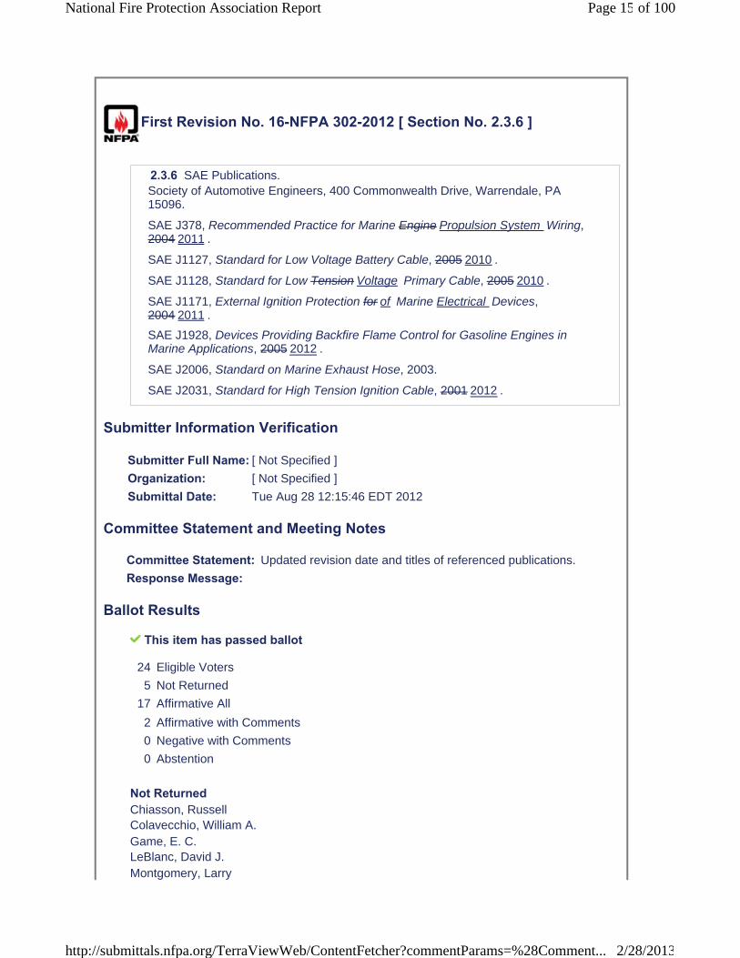
First Revision No. 16-NFPA 302-2012 [ Section No. 2.3.6 ]
2.3.6 SAE Publications.Society of Automotive Engineers, 400 Commonwealth Drive, Warrendale, PA 15096.
SAE J378, Recommended Practice for Marine Engine Propulsion System Wiring, 2004 2011 .
SAE J1127, Standard for Low Voltage Battery Cable, 2005 2010 .
SAE J1128, Standard for Low Tension Voltage Primary Cable, 2005 2010 .
SAE J1171, External Ignition Protection for of Marine Electrical Devices, 2004 2011 .
SAE J1928, Devices Providing Backfire Flame Control for Gasoline Engines in Marine Applications, 2005 2012 .
SAE J2006, Standard on Marine Exhaust Hose, 2003.
SAE J2031, Standard for High Tension Ignition Cable, 2001 2012 .
Submitter Information Verification
Submitter Full Name: [ Not Specified ]
Organization: [ Not Specified ]
Submittal Date: Tue Aug 28 12:15:46 EDT 2012
Committee Statement and Meeting Notes
Committee Statement: Updated revision date and titles of referenced publications.
Response Message:
Ballot Results
This item has passed ballot
24 Eligible Voters
5 Not Returned
17 Affirmative All
2 Affirmative with Comments
0 Negative with Comments
0 Abstention
Not ReturnedChiasson, RussellColavecchio, William A. Game, E. C.LeBlanc, David J. Montgomery, Larry
Page 15 of 100National Fire Protection Association Report
2/28/2013http://submittals.nfpa.org/TerraViewWeb/ContentFetcher?commentParams=%28Comment...
Affirmative All, , , , , , , , , , , , , , , , ,
Affirmative with CommentAdey, John AffirmMcFarlin, David Although voting affirmative, I think more study needs to be done relative to the newedition standards and how they may have an affect on 302.
Page 16 of 100National Fire Protection Association Report
2/28/2013http://submittals.nfpa.org/TerraViewWeb/ContentFetcher?commentParams=%28Comment...
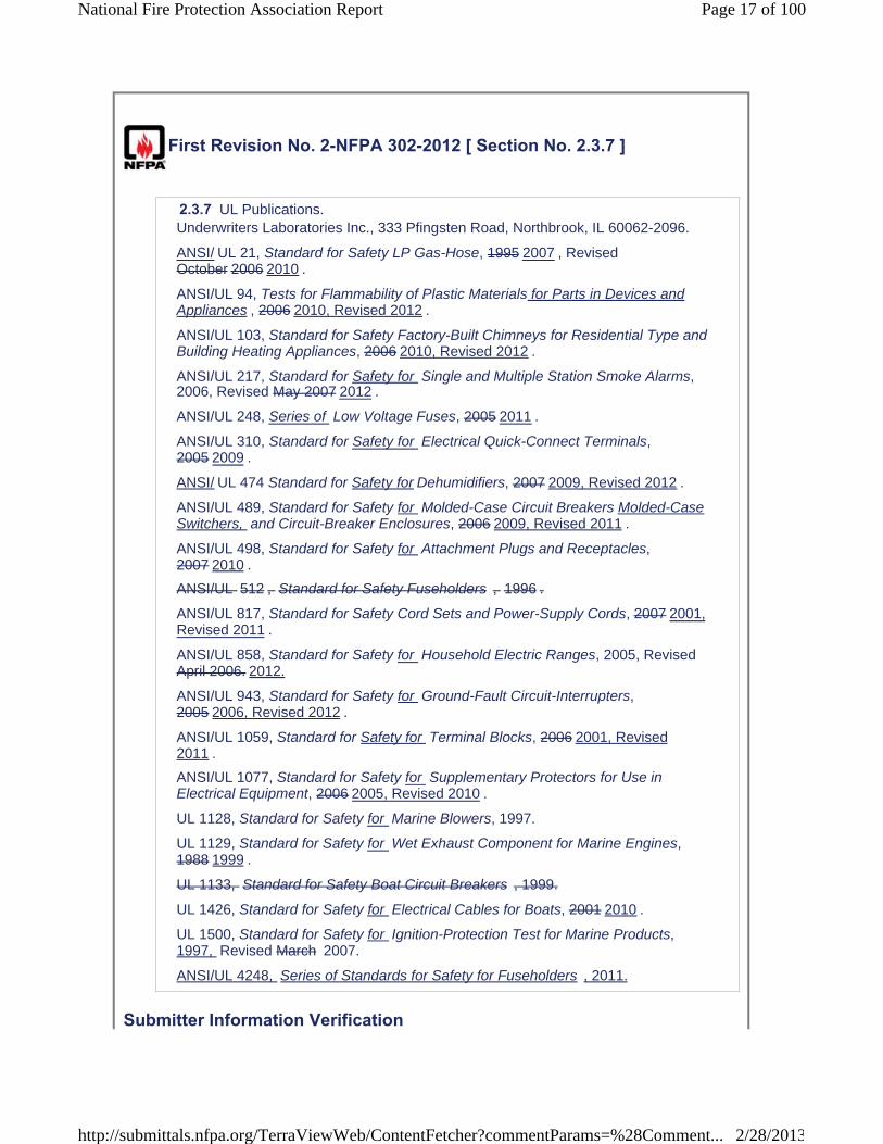
First Revision No. 2-NFPA 302-2012 [ Section No. 2.3.7 ]
2.3.7 UL Publications.Underwriters Laboratories Inc., 333 Pfingsten Road, Northbrook, IL 60062-2096.
ANSI/ UL 21, Standard for Safety LP Gas-Hose, 1995 2007 , RevisedOctober 2006 2010 .
ANSI/UL 94, Tests for Flammability of Plastic Materials for Parts in Devices and Appliances , 2006 2010, Revised 2012 .
ANSI/UL 103, Standard for Safety Factory-Built Chimneys for Residential Type and Building Heating Appliances, 2006 2010, Revised 2012 .
ANSI/UL 217, Standard for Safety for Single and Multiple Station Smoke Alarms, 2006, Revised May 2007 2012 .
ANSI/UL 248, Series of Low Voltage Fuses, 2005 2011 .
ANSI/UL 310, Standard for Safety for Electrical Quick-Connect Terminals,2005 2009 .
ANSI/ UL 474 Standard for Safety for Dehumidifiers, 2007 2009, Revised 2012 .
ANSI/UL 489, Standard for Safety for Molded-Case Circuit Breakers Molded-Case Switchers, and Circuit-Breaker Enclosures, 2006 2009, Revised 2011 .
ANSI/UL 498, Standard for Safety for Attachment Plugs and Receptacles,2007 2010 .
ANSI/UL 512 , Standard for Safety Fuseholders , 1996 .
ANSI/UL 817, Standard for Safety Cord Sets and Power-Supply Cords, 2007 2001, Revised 2011 .
ANSI/UL 858, Standard for Safety for Household Electric Ranges, 2005, Revised April 2006. 2012.
ANSI/UL 943, Standard for Safety for Ground-Fault Circuit-Interrupters, 2005 2006, Revised 2012 .
ANSI/UL 1059, Standard for Safety for Terminal Blocks, 2006 2001, Revised 2011 .
ANSI/UL 1077, Standard for Safety for Supplementary Protectors for Use in Electrical Equipment, 2006 2005, Revised 2010 .
UL 1128, Standard for Safety for Marine Blowers, 1997.
UL 1129, Standard for Safety for Wet Exhaust Component for Marine Engines, 1988 1999 .
UL 1133, Standard for Safety Boat Circuit Breakers , 1999.
UL 1426, Standard for Safety for Electrical Cables for Boats, 2001 2010 .
UL 1500, Standard for Safety for Ignition-Protection Test for Marine Products, 1997, Revised March 2007.
ANSI/UL 4248, Series of Standards for Safety for Fuseholders , 2011.
Submitter Information Verification
Page 17 of 100National Fire Protection Association Report
2/28/2013http://submittals.nfpa.org/TerraViewWeb/ContentFetcher?commentParams=%28Comment...
Submitter Full Name: [ Not Specified ]
Organization: [ Not Specified ]
Submittal Date: Tue Aug 28 10:30:05 EDT 2012
Committee Statement and Meeting Notes
CommitteeStatement:
Update title of ANSI/UL 94 as indicated and update other referenced standards to most recent edition as indicated.
ResponseMessage:Public Input No. 1-NFPA 302-2012 [Section No. 2.3.7]
Ballot Results
This item has passed ballot
24 Eligible Voters
5 Not Returned
17 Affirmative All
2 Affirmative with Comments
0 Negative with Comments
0 Abstention
Not ReturnedChiasson, RussellColavecchio, William A. Game, E. C.LeBlanc, David J. Montgomery, Larry
Affirmative All, , , , , , , , , , , , , , , , ,
Affirmative with Comment
Page 18 of 100National Fire Protection Association Report
2/28/2013http://submittals.nfpa.org/TerraViewWeb/ContentFetcher?commentParams=%28Comment...

Adey, John AffirmMcFarlin, David Although voting affirmative, I think more study needs to be done relative to the new edition standards and how they may have an affect on 302.
Page 19 of 100National Fire Protection Association Report
2/28/2013http://submittals.nfpa.org/TerraViewWeb/ContentFetcher?commentParams=%28Comment...

First Revision No. 17-NFPA 302-2012 [ Section No. 2.4 ]
2.4 References for Extracts in Mandatory Sections.
NFPA 70®, National Electrical Code®, 2008 2011 edition.
NFPA 2001, Standard on Clean Agent Fire Extinguishing Systems, 2008 2012edition.
Submitter Information Verification
Submitter Full Name: [ Not Specified ]
Organization: [ Not Specified ]
Submittal Date: Tue Aug 28 12:21:26 EDT 2012
Committee Statement and Meeting Notes
Committee Statement: Updated revision dates of referenced documents.
Response Message:
Ballot Results
This item has passed ballot
24 Eligible Voters
5 Not Returned
17 Affirmative All
2 Affirmative with Comments
0 Negative with Comments
0 Abstention
Not ReturnedChiasson, RussellColavecchio, William A. Game, E. C.LeBlanc, David J. Montgomery, Larry
Affirmative All, , , , , , , , ,
Page 20 of 100National Fire Protection Association Report
2/28/2013http://submittals.nfpa.org/TerraViewWeb/ContentFetcher?commentParams=%28Comment...

, , , , , , , ,
Affirmative with CommentAdey, John AffirmMcFarlin, David Although voting affirmative, I think more study needs to be done relative to the new edition standards and how they may have an affect on 302.
Page 21 of 100National Fire Protection Association Report
2/28/2013http://submittals.nfpa.org/TerraViewWeb/ContentFetcher?commentParams=%28Comment...
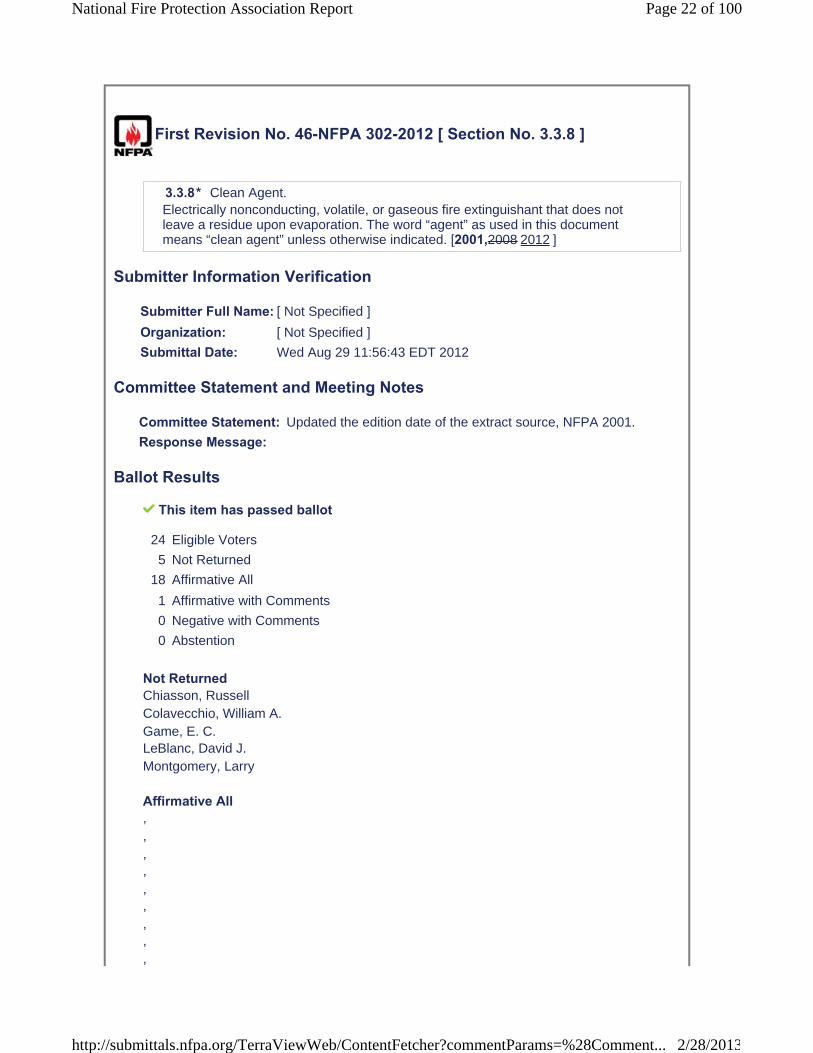
First Revision No. 46-NFPA 302-2012 [ Section No. 3.3.8 ]
3.3.8* Clean Agent.Electrically nonconducting, volatile, or gaseous fire extinguishant that does not leave a residue upon evaporation. The word “agent” as used in this document means “clean agent” unless otherwise indicated. [2001,2008 2012 ]
Submitter Information Verification
Submitter Full Name: [ Not Specified ]
Organization: [ Not Specified ]
Submittal Date: Wed Aug 29 11:56:43 EDT 2012
Committee Statement and Meeting Notes
Committee Statement: Updated the edition date of the extract source, NFPA 2001.
Response Message:
Ballot Results
This item has passed ballot
24 Eligible Voters
5 Not Returned
18 Affirmative All
1 Affirmative with Comments
0 Negative with Comments
0 Abstention
Not ReturnedChiasson, RussellColavecchio, William A. Game, E. C.LeBlanc, David J. Montgomery, Larry
Affirmative All, , , , , , , , ,
Page 22 of 100National Fire Protection Association Report
2/28/2013http://submittals.nfpa.org/TerraViewWeb/ContentFetcher?commentParams=%28Comment...

, , , , , , , , ,
Affirmative with CommentAdey, John Affirm
Page 23 of 100National Fire Protection Association Report
2/28/2013http://submittals.nfpa.org/TerraViewWeb/ContentFetcher?commentParams=%28Comment...
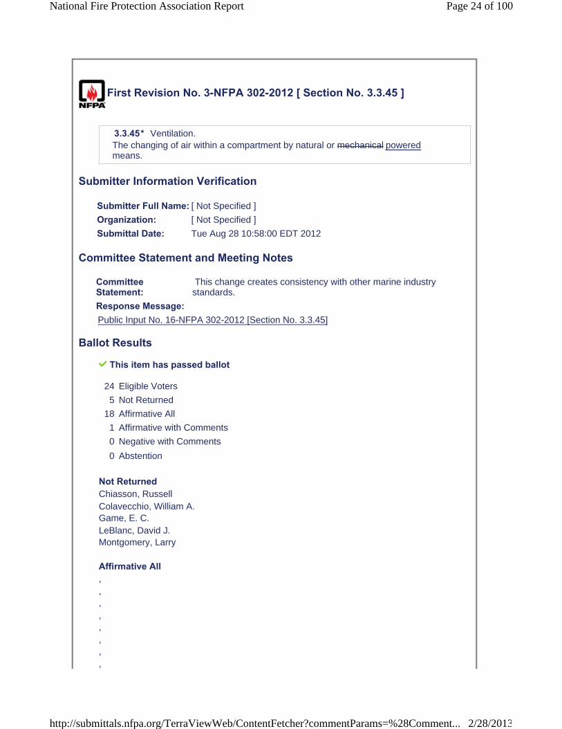
First Revision No. 3-NFPA 302-2012 [ Section No. 3.3.45 ]
3.3.45* Ventilation.The changing of air within a compartment by natural or mechanical poweredmeans.
Submitter Information Verification
Submitter Full Name: [ Not Specified ]
Organization: [ Not Specified ]
Submittal Date: Tue Aug 28 10:58:00 EDT 2012
Committee Statement and Meeting Notes
CommitteeStatement:
This change creates consistency with other marine industry standards.
Response Message:Public Input No. 16-NFPA 302-2012 [Section No. 3.3.45]
Ballot Results
This item has passed ballot
24 Eligible Voters
5 Not Returned
18 Affirmative All
1 Affirmative with Comments
0 Negative with Comments
0 Abstention
Not ReturnedChiasson, RussellColavecchio, William A. Game, E. C.LeBlanc, David J. Montgomery, Larry
Affirmative All, , , , , , , ,
Page 24 of 100National Fire Protection Association Report
2/28/2013http://submittals.nfpa.org/TerraViewWeb/ContentFetcher?commentParams=%28Comment...

, , , , , , , , , ,
Affirmative with CommentAdey, John Affirm
Page 25 of 100National Fire Protection Association Report
2/28/2013http://submittals.nfpa.org/TerraViewWeb/ContentFetcher?commentParams=%28Comment...
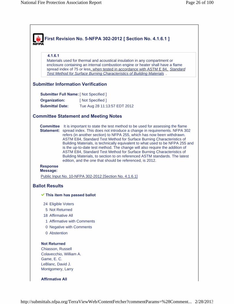
First Revision No. 5-NFPA 302-2012 [ Section No. 4.1.6.1 ]
4.1.6.1Materials used for thermal and acoustical insulation in any compartment or enclosure containing an internal combustion engine or heater shall have a flame spread index of 75 or less, when tested in accordance with ASTM E 84, Standard Test Method for Surface Burning Characteristics of Building Materials .
Submitter Information Verification
Submitter Full Name: [ Not Specified ]
Organization: [ Not Specified ]
Submittal Date: Tue Aug 28 11:13:57 EDT 2012
Committee Statement and Meeting Notes
CommitteeStatement:
It is important to state the test method to be used for assessing the flame spread index. This does not introduce a change in requirements. NFPA 302 refers (in another section) to NFPA 255, which has now been withdrawn. ASTM E84, Standard Test Method for Surface Burning Characteristics of Building Materials, is technically equivalent to what used to be NFPA 255 and is the up-to-date test method. The change will also require the addition of ASTM E84, Standard Test Method for Surface Burning Characteristics of Building Materials, to section to on referenced ASTM standards. The latest edition, and the one that should be referenced, is 2012.
ResponseMessage:Public Input No. 10-NFPA 302-2012 [Section No. 4.1.6.1]
Ballot Results
This item has passed ballot
24 Eligible Voters
5 Not Returned
18 Affirmative All
1 Affirmative with Comments
0 Negative with Comments
0 Abstention
Not ReturnedChiasson, RussellColavecchio, William A. Game, E. C.LeBlanc, David J. Montgomery, Larry
Affirmative All
Page 26 of 100National Fire Protection Association Report
2/28/2013http://submittals.nfpa.org/TerraViewWeb/ContentFetcher?commentParams=%28Comment...

, , , , , , , , , , , , , , , , , ,
Affirmative with CommentAdey, John Affirm
Page 27 of 100National Fire Protection Association Report
2/28/2013http://submittals.nfpa.org/TerraViewWeb/ContentFetcher?commentParams=%28Comment...
First Revision No. 6-NFPA 302-2012 [ Section No. 4.1.6.2 ]
4.1.6.2Material shall be labeled or listed as having been tested to meet the requirements of NFPA 255 , Standard Method of Test of Surface Burning Characteristics of Building Materials ASTM E 84, Standard Test Method for Surface Burning Characteristics of Building Materials .
Submitter Information Verification
Submitter Full Name: [ Not Specified ]
Organization: [ Not Specified ]
Submittal Date: Tue Aug 28 11:14:33 EDT 2012
Committee Statement and Meeting Notes
CommitteeStatement:
NFPA 255 was withdrawn in 2009. The requirements are found in ASTM E84.
Response Message:
Ballot Results
This item has passed ballot
24 Eligible Voters
5 Not Returned
18 Affirmative All
1 Affirmative with Comments
0 Negative with Comments
0 Abstention
Not Returned, Russell Chiasson, William A. ColavecchioGame, E. C.LeBlanc, David J. Montgomery, Larry
Affirmative All, , , , , , , ,
Page 28 of 100National Fire Protection Association Report
2/28/2013http://submittals.nfpa.org/TerraViewWeb/ContentFetcher?commentParams=%28Comment...

, , , , , , , , , ,
Affirmative with CommentAdey, John Affirm
Page 29 of 100National Fire Protection Association Report
2/28/2013http://submittals.nfpa.org/TerraViewWeb/ContentFetcher?commentParams=%28Comment...
First Revision No. 7-NFPA 302-2012 [ New Section after 4.5.1 ]
Global FR-7 Hide Deleted
4.5.1.1Each compartment not open to the atmosphere that has a permanently installed internal combustion engine with a cranking motor and a fixed fire extinguishing system shall be ventilated by an exhaust blower to remove any by-products of combustion or remaining extinguishing agent after the discharge of a fixed fire extinguishing system..
Submitter Information Verification
Submitter Full Name: [ Not Specified ]
Organization: [ Not Specified ]
Submittal Date: Tue Aug 28 11:19:12 EDT 2012
Committee Statement and Meeting Notes
Committee Statement: This material was moved from Public Input 6
Response Message:
Ballot Results
This item has passed ballot
24 Eligible Voters
5 Not Returned
18 Affirmative All
1 Affirmative with Comments
0 Negative with Comments
0 Abstention
Not ReturnedChiasson, RussellColavecchio, William A. Game, E. C.LeBlanc, David J. Montgomery, Larry
Affirmative All, , , , , ,
Page 30 of 100National Fire Protection Association Report
2/28/2013http://submittals.nfpa.org/TerraViewWeb/ContentFetcher?commentParams=%28Comment...

, , , , , , , , , , , ,
Affirmative with CommentAdey, John Affirm
Page 31 of 100National Fire Protection Association Report
2/28/2013http://submittals.nfpa.org/TerraViewWeb/ContentFetcher?commentParams=%28Comment...

First Revision No. 48-NFPA 302-2012 [ Section No. 4.5.2.2 ]
4.5.2.2*Blowers shall meet the external ignition protection requirements of UL 1128, Standard for Safety for Marine Blowers, or UL 1500, Standard for Safety for Ignition-Protection Test for Marine Products.
Submitter Information Verification
Submitter Full Name: [ Not Specified ]
Organization: [ Not Specified ]
Submittal Date: Wed Aug 29 12:59:38 EDT 2012
Committee Statement and Meeting Notes
CommitteeStatement:
The title of the referenced UL document in this requirement is revised in accord with FR-2-NFPA 302-2012
Response Message:
Ballot Results
This item has passed ballot
24 Eligible Voters
5 Not Returned
18 Affirmative All
1 Affirmative with Comments
0 Negative with Comments
0 Abstention
Not ReturnedChiasson, RussellColavecchio, William A. Game, E. C.LeBlanc, David J. Montgomery, Larry
Affirmative All, , , , , , , ,
Page 32 of 100National Fire Protection Association Report
2/28/2013http://submittals.nfpa.org/TerraViewWeb/ContentFetcher?commentParams=%28Comment...
, , , , , , , , , ,
Affirmative with CommentAdey, John Affirm
Page 33 of 100National Fire Protection Association Report
2/28/2013http://submittals.nfpa.org/TerraViewWeb/ContentFetcher?commentParams=%28Comment...
First Revision No. 8-NFPA 302-2012 [ New Section after 4.5.3.2 ]
Global FR-8 Hide Deleted
4.5.3.2.1Each blower shall be separately circuited and protected internally at the equipment or by branch-circuit overcurrent devices suitable for motor current.
Submitter Information Verification
Submitter Full Name: [ Not Specified ]
Organization: [ Not Specified ]
Submittal Date: Tue Aug 28 11:42:44 EDT 2012
Committee Statement and Meeting Notes
CommitteeStatement:
Committee determined that an additional level of safety was needed for blowers.
Response Message:
Ballot Results
This item has passed ballot
24 Eligible Voters
5 Not Returned
18 Affirmative All
1 Affirmative with Comments
0 Negative with Comments
0 Abstention
Not ReturnedChiasson, RussellColavecchio, William A. Game, E. C.LeBlanc, David J. Montgomery, Larry
Affirmative All, , , , , , , ,
Page 34 of 100National Fire Protection Association Report
2/28/2013http://submittals.nfpa.org/TerraViewWeb/ContentFetcher?commentParams=%28Comment...

, , , , , , , , , ,
Affirmative with CommentAdey, John Affirm
Page 35 of 100National Fire Protection Association Report
2/28/2013http://submittals.nfpa.org/TerraViewWeb/ContentFetcher?commentParams=%28Comment...
First Revision No. 10-NFPA 302-2012 [ Section No. 5.5.3.2.1 ]
5.5.3.2.1Ducts for engine-cooling air shall have a flame spread index of 75 or less, when tested in accordance with ASTM E 84, Standard Test Method for Surface BurningCharacteristics of Building Materials .
Submitter Information Verification
Submitter Full Name: [ Not Specified ]
Organization: [ Not Specified ]
Submittal Date: Tue Aug 28 11:50:09 EDT 2012
Committee Statement and Meeting Notes
CommitteeStatement:
It is important to state the test method to be used for assessing the flame spread index. This does not introduce a change in requirements. NFPA 302 refers (in another section) to NFPA 255, which has now been withdrawn. ASTM E84, Standard Test Method for Surface Burning Characteristics of Building Materials, is technically equivalent to what used to be NFPA 255 and is the up-to-date test method. The change will also require the addition of ASTM E84, Standard Test Method for Surface Burning Characteristics of Building Materials, to section to on referenced ASTM standards. The latest edition, and the one that should be referenced, is 2012.
ResponseMessage:Public Input No. 11-NFPA 302-2012 [Section No. 5.5.3.2.1]
Ballot Results
This item has passed ballot
24 Eligible Voters
5 Not Returned
18 Affirmative All
1 Affirmative with Comments
0 Negative with Comments
0 Abstention
Not ReturnedChiasson, RussellColavecchio, William A. Game, E. C.LeBlanc, David J. Montgomery, Larry
Affirmative All,
Page 36 of 100National Fire Protection Association Report
2/28/2013http://submittals.nfpa.org/TerraViewWeb/ContentFetcher?commentParams=%28Comment...
, , , , , , , , , , , , , , , , ,
Affirmative with CommentAdey, John Affirm
Page 37 of 100National Fire Protection Association Report
2/28/2013http://submittals.nfpa.org/TerraViewWeb/ContentFetcher?commentParams=%28Comment...

First Revision No. 11-NFPA 302-2012 [ Section No. 5.5.3.2.2 ]
5.5.3.2.2Material used for ducts for engine-cooling air shall be labeled or listed as having been tested to meet the requirements of NFPA 255 , Standard Method of Test of Surface Burning Characteristics of Building Materials ASTM E 84, Standard Test Method of Test of for Surface Burning Characteristics of Building Materials . .
Submitter Information Verification
Submitter Full Name: [ Not Specified ]
Organization: [ Not Specified ]
Submittal Date: Tue Aug 28 11:52:16 EDT 2012
Committee Statement and Meeting Notes
CommitteeStatement:
NFPA 255 was withdrawn in 2009. The requirements are now found in ASTM E84.
Response Message:
Ballot Results
This item has passed ballot
24 Eligible Voters
5 Not Returned
18 Affirmative All
1 Affirmative with Comments
0 Negative with Comments
0 Abstention
Not ReturnedChiasson, RussellColavecchio, William A. Game, E. C.LeBlanc, David J. Montgomery, Larry
Affirmative All, , , , , , ,
Page 38 of 100National Fire Protection Association Report
2/28/2013http://submittals.nfpa.org/TerraViewWeb/ContentFetcher?commentParams=%28Comment...
, , , , , , , , , , ,
Affirmative with CommentAdey, John Affirm
Page 39 of 100National Fire Protection Association Report
2/28/2013http://submittals.nfpa.org/TerraViewWeb/ContentFetcher?commentParams=%28Comment...
First Revision No. 19-NFPA 302-2012 [ Section No. 6.1.1 ]
6.1.1Exhaust systems shall comply with the following:
(1) They shall be gastight to hull interiors.
(2) All connections shall be accessible.
(3) They shall be supported to minimize failure from vibration, shock, expansion, and contraction.
(4) They shall have no threaded fittings into nonmetallic exhaust system components.
(5) They shall have no discharge from other devices into the exhaust other than from engine-cooling water.
Global FR-19 Hide Deleted
6.1.1.1In addition to the requirements of 6.1.1 , exhaust systems on gasoline engines shall be designed and installed to reduce the production of carbon monoxide by providing the minimum restrictions to exhaust gas flow practicable.
Submitter Information Verification
Submitter Full Name: [ Not Specified ]
Organization: [ Not Specified ]
Submittal Date: Tue Aug 28 12:36:33 EDT 2012
Committee Statement and Meeting Notes
CommitteeStatement:
Bob Loeser did extensive testing on this subject and found that by reducing the number of elbows and other restriction to exhaust gas flow the level of CO production could be reduced by several magnitudes. This reduction also lead to increased fuel economy.
ResponseMessage:Public Input No. 7-NFPA 302-2012 [Section No. 6.1.1]
Ballot Results
This item has passed ballot
24 Eligible Voters
5 Not Returned
17 Affirmative All
1 Affirmative with Comments
1 Negative with Comments
0 Abstention
Page 40 of 100National Fire Protection Association Report
2/28/2013http://submittals.nfpa.org/TerraViewWeb/ContentFetcher?commentParams=%28Comment...
Not ReturnedChiasson, RussellColavecchio, William A. Game, E. C.LeBlanc, David J. Montgomery, Larry
Affirmative All, , , , , , , , , , , , , , , , ,
Affirmative with CommentNewsome, Robert E. Add "as" before practicable, as follows: In addition to the requirements of 6.1.1, exhaustsystems on gasoline engines shall be designed and installed to reduce the production of carbon monoxide by providing the minimum restrictions to exhaust gas flow as practicable.
Negative with CommentAdey, John There is no method of compliance with this statement. It is written as a requirement but clearly has the language of a NOTE. Recommend changing to a NOTE.
Page 41 of 100National Fire Protection Association Report
2/28/2013http://submittals.nfpa.org/TerraViewWeb/ContentFetcher?commentParams=%28Comment...

First Revision No. 37-NFPA 302-2012 [ Section No. 7.2.2.2 ]
7.2.2.2Materials shall meet the specifications of Table 7.2.2.2.Table 7.2.2.2 Metallic Fuel Tank Material and Fabrication Requirements for Corrosion Resistance
Materiala SpecificationMinimum Nominal Sheet
Thickness Gauge
Nickel-copper ASTM B127, Class A 0.031 in. (0.79 mm) 22 U.S. Std.
Copper-nickel ASTM B122 0.045 in. (1.14 mm) 17 AWG
Copper ASTM B152, Type E.T.P. 0.057 in. (1.45 mm) 15 AWG
Copper-silicon
ASTM B97 B96/B96M , Types A, B, and G 0.050 in. (1.27 mm) 16 AWG
Steel sheet ASTM A653/A653M 0.0747 in. (1.90 mm) 14 Mfrs.
Aluminized steel
ASTM A463 0.0478 in. (1.21 mm) 18 Mfrs.
Aluminum Alloy 5052, 5083, or 5086 0.090 in. (2.29 mm) —
Stainless steel 316L or 317L
0.0747 in. (1.90 mm) 0.031 in. (0.79 mm)b
14 Mfrs.
22 U.S. Std.b
aSee American Welding Society recommendations for welding processes.
bOnly cylindrical stainless steel tanks with domed heads and a capacity of less than 20 gal (76 L) are permitted.
Submitter Information Verification
Submitter Full Name: [ Not Specified ]
Organization: [ Not Specified ]
Submittal Date: Tue Aug 28 15:59:36 EDT 2012
Committee Statement and Meeting Notes
CommitteeStatement:
Change made to incorporate a revision of the document, from ASTM B97 to ASTM B96/B96 M.
Response Message:
Ballot Results
This item has passed ballot
Page 42 of 100National Fire Protection Association Report
2/28/2013http://submittals.nfpa.org/TerraViewWeb/ContentFetcher?commentParams=%28Comment...

24 Eligible Voters
5 Not Returned
18 Affirmative All
1 Affirmative with Comments
0 Negative with Comments
0 Abstention
Not ReturnedChiasson, RussellColavecchio, William A. Game, E. C.LeBlanc, David J. Montgomery, Larry
Affirmative All, , , , , , , , , , , , , , , , , ,
Affirmative with CommentAdey, John Affirm
Page 43 of 100National Fire Protection Association Report
2/28/2013http://submittals.nfpa.org/TerraViewWeb/ContentFetcher?commentParams=%28Comment...
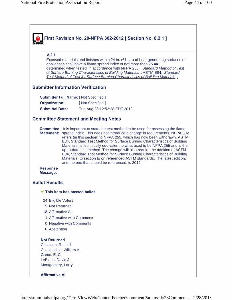
First Revision No. 20-NFPA 302-2012 [ Section No. 8.2.1 ]
8.2.1Exposed materials and finishes within 24 in. (61 cm) of heat-generating surfaces of appliances shall have a flame spread index of not more than 75 as determined when tested in accordance with NFPA 255 , Standard Method of Test of Surface Burning Characteristics of Building Materials . ASTM E84, StandardTest Method of Test for Surface Burning Characteristics of Building Materials .
Submitter Information Verification
Submitter Full Name: [ Not Specified ]
Organization: [ Not Specified ]
Submittal Date: Tue Aug 28 12:52:28 EDT 2012
Committee Statement and Meeting Notes
CommitteeStatement:
It is important to state the test method to be used for assessing the flame spread index. This does not introduce a change in requirements. NFPA 302 refers (in this section) to NFPA 255, which has now been withdrawn. ASTM E84, Standard Test Method for Surface Burning Characteristics of Building Materials, is technically equivalent to what used to be NFPA 255 and is the up-to-date test method. The change will also require the addition of ASTM E84, Standard Test Method for Surface Burning Characteristics of Building Materials, to section to on referenced ASTM standards. The latest edition, and the one that should be referenced, is 2012.
ResponseMessage:
Ballot Results
This item has passed ballot
24 Eligible Voters
5 Not Returned
18 Affirmative All
1 Affirmative with Comments
0 Negative with Comments
0 Abstention
Not ReturnedChiasson, RussellColavecchio, William A. Game, E. C.LeBlanc, David J. Montgomery, Larry
Affirmative All
Page 44 of 100National Fire Protection Association Report
2/28/2013http://submittals.nfpa.org/TerraViewWeb/ContentFetcher?commentParams=%28Comment...
, , , , , , , , , , , , , , , , , ,
Affirmative with CommentAdey, John Affirm
Page 45 of 100National Fire Protection Association Report
2/28/2013http://submittals.nfpa.org/TerraViewWeb/ContentFetcher?commentParams=%28Comment...

First Revision No. 22-NFPA 302-2012 [ Section No. 8.2.2 ]
8.2.2Fabrics located above and within 39 in. (1 m) of a galley stove top, used for decorative or other purposes, shall be flame resistant in accordance with shall meet the flame propagation performance criteria contained in Test Method 1 or Test Method 2, as appropriate, of NFPA 701, Standard Methods of Fire Tests forFlame Propagation of Textiles and Films.
Submitter Information Verification
Submitter Full Name: [ Not Specified ]
Organization: [ Not Specified ]
Submittal Date: Tue Aug 28 13:01:53 EDT 2012
Committee Statement and Meeting Notes
Page 46 of 100National Fire Protection Association Report
2/28/2013http://submittals.nfpa.org/TerraViewWeb/ContentFetcher?commentParams=%28Comment...

CommitteeStatement:
The term "flame resistant" has been changed in most NFPA and ICC codes by the phrase "meet the flame propagation performance criteria" because it is more accurate and because the term flame resistant is vague and unenforceable. The remainder of the proposed change is explained below and is being implemented in other codes and standards also. In 1989 the NFPA Technical Committee on Fire Tests eliminated the so-called “small-scale test” from NFPA 701 because the results had been shown not to represent a fire performance that corresponded to what happened in real scale. Instead of the “small-scale test” NFPA 701 now (and for over 20 years) contains two tests (Test 1 and Test 2), which apply to materials as indicated by the text of NFPA 701 (2010) that is shown at the bottom of this public input. However, a largenumber of manufacturers continue stating that the materials or products that they sell have been tested to NFPA 701, when they really mean the pre-1989 small-scale test in NFPA 701. That test no longer exists and materials or products meeting that test do not exhibit acceptable fire performance. Text of NFPA 701 (2010): 1.1.1.1 Test Method 1 shall apply to fabrics or other materials used in curtains, draperies, or other window treatments. Vinyl-coated fabric blackout linings shall be tested according to Test Method 2. 1.1.1.2 Test Method 1 shall apply to single-layer fabrics and to multilayer curtain and drapery assemblies in which the layers are fastened together by sewing or other means. Vinyl-coated fabric blackout linings shall be tested according to Test Method 2. 1.1.1.3 Test Method 1 shall apply to specimens having an areal density less than or equal to 700 g/m2 (21 oz/yd2), except where Test Method 2 is required to be used by 1.1.2. 1.1.2.1 Test Method 2 (flat specimen configuration) shall be used for fabrics, including multilayered fabrics, films, and plastic blinds, with or without reinforcement or backing, with arealdensities greater than 700 g/m2 (21 oz/yd2). 1.1.2.2 Test Method 2 shall be used for testing vinyl-coated fabric blackout linings and lined draperies using a vinyl-coated fabric blackout lining. 1.1.2.3 Test Method 2 shall be used for testing plastic films, with or without reinforcement or backing, when used for decorative or other purposes inside a building or as temporary or permanent enclosures for buildings under construction. 1.1.2.4 Test Method 2 shall apply to fabrics used in the assembly of awnings, tents, tarps, and similar architectural fabric structures and banners. Note also the following from the text of NFPA 701 (2010): 1.2* Purpose. 1.2.1 The purpose of Test Methods 1 and 2 shall be to assess the propagation of flame beyond the area exposed to the ignition source. A.1.1 A small-scale test method appeared in NFPA 701 until the 1989 edition. It was eliminated from the test method because it has been shown that materials that “pass” the test do not necessarily exhibit a fireperformance that is acceptable. The test was not reproducible for many types of fabrics and could not predict actual full-scale performance. It should not, therefore, be used. A.1.1.1 For the purposes of Test Method 1, the terms curtains, draperies, or other types of window treatments, where used, should include, but not be limited to, the following items: (1) Window curtains (2) Stage or theater curtains (3) Vertical folding shades (4) Roll-type window shades (5) Hospital privacy curtains (6) Window draperies (7) Fabric shades or blinds (8) Polyvinyl chloride blinds (9) Horizontal folding shades (10) Swags Examples of textile items other than window treatments to which Test Method 1 applies include: (1) Table skirts (2) Table linens (3) Display booth separators (4) Textile wall hangings (5) Decorative event tent linings not used in the assembly of a tent
ResponseMessage:Public Input No. 9-NFPA 302-2012 [Section No. 8.2.2]
Ballot Results
This item has passed ballot
Page 47 of 100National Fire Protection Association Report
2/28/2013http://submittals.nfpa.org/TerraViewWeb/ContentFetcher?commentParams=%28Comment...

24 Eligible Voters
5 Not Returned
18 Affirmative All
1 Affirmative with Comments
0 Negative with Comments
0 Abstention
Not ReturnedChiasson, RussellColavecchio, William A. Game, E. C.LeBlanc, David J. Montgomery, Larry
Affirmative All, , , , , , , , , , , , , , , , , ,
Affirmative with CommentAdey, John This is a new requirement and may or may not meet the criteria in ABYC A-3 Galley Stoves OR ISO 9094 Fire Protection. These documents are harmonized when it comes to zones and testing. Time is needed to research the compatibility of this newer standard with existing industry standards.
Page 48 of 100National Fire Protection Association Report
2/28/2013http://submittals.nfpa.org/TerraViewWeb/ContentFetcher?commentParams=%28Comment...

First Revision No. 54-NFPA 302-2012 [ Section No. 9.9.8 ]
9.9.8 Circuit Breakers.The following shall apply to circuit breakers:
(1) They shall have a dc voltage rating of not less than the nominal system voltage.
(2) They shall be of the trip-free type.
(3) They shall be capable of an interrupting capacity in accordance with Table 9.9.8(a).
(4)
(5)
Table 9.9.8(a) Circuit Breaker Minimum Amperage Interrupting Capacity
Ampere Interrupting Capacity (AIC) (Amperage available at circuit breaker
terminals)Cold Cranking Current Rating at 0°F (-18°C) of Total Connected
Battery CapacityMain Circuit
Breaker (Amperes)Branch Circuit
Breaker (Amperes)12 volts and 24 volts
650 or less 1500 750
651–1100 3000 1500
Over 1100 5000 2500
32 volts
1250 or less 3000 1500
Over 1250 5000 2500
Notes:
(1) The main circuit breaker is considered to be the first breaker(s) in a circuit connected in series with the battery. All subsequent breakers connected in series with a main circuit breaker are considered to be branch circuit breakers.
(2) Under Battery Council International conversion factors, the following approximate correlations are used for 0°F (-18°C):
(a) ANSI/UL 489, Standard for Safety for Molded-Case Circuit Breakers and Circuit-Breaker Enclosures
(b) ANSI/UL 1077, Standard for Safety for Supplementary Protectors for Use in Electrical Equipment, if used as a branch circuit breaker and able to interrupt the current specified for branch circuit breakers in Table 9.9.8(a) alone or in combination with the main circuit breaker
UL 1133, Standard for Safety Boat Circuit Breakers
* They shall meet the marine requirements of one of the following:
* If located in a space that requires ignition protection, they shall meet the requirements of UL 1500, Standard for Safety for Ignition-Protection Test for Marine Products, at four times their rated current.
Page 49 of 100National Fire Protection Association Report
2/28/2013http://submittals.nfpa.org/TerraViewWeb/ContentFetcher?commentParams=%28Comment...
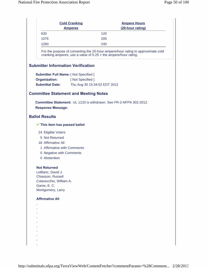
Cold Cranking Amperes
Ampere Hours (20-hour rating)
630 120
1076 205
1260 240
For the purpose of converting the 20-hour ampere/hour rating to approximate cold cranking amperes, use a value of 5.25 × the ampere/hour rating.
Submitter Information Verification
Submitter Full Name: [ Not Specified ]
Organization: [ Not Specified ]
Submittal Date: Thu Aug 30 15:34:52 EDT 2012
Committee Statement and Meeting Notes
Committee Statement: UL 1133 is withdrawn. See FR-2-NFPA 302-2012.
Response Message:
Ballot Results
This item has passed ballot
24 Eligible Voters
5 Not Returned
18 Affirmative All
1 Affirmative with Comments
0 Negative with Comments
0 Abstention
Not ReturnedLeBlanc, David J.Chiasson, Russell Colavecchio, William A.Game, E. C. Montgomery, Larry
Affirmative All, , , , , , , , , ,
Page 50 of 100National Fire Protection Association Report
2/28/2013http://submittals.nfpa.org/TerraViewWeb/ContentFetcher?commentParams=%28Comment...
, , , , , , , ,
Affirmative with CommentAdey, John Affirm
Page 51 of 100National Fire Protection Association Report
2/28/2013http://submittals.nfpa.org/TerraViewWeb/ContentFetcher?commentParams=%28Comment...
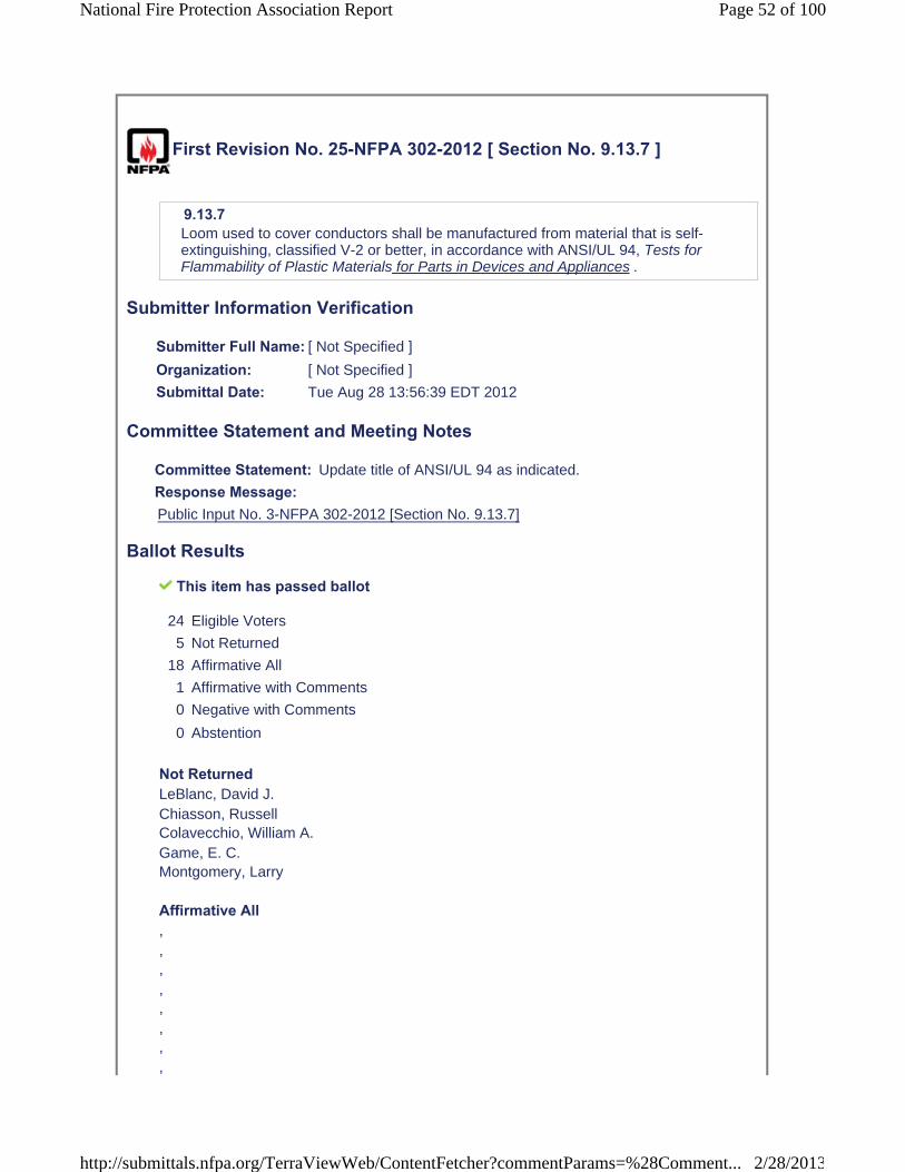
First Revision No. 25-NFPA 302-2012 [ Section No. 9.13.7 ]
9.13.7Loom used to cover conductors shall be manufactured from material that is self-extinguishing, classified V-2 or better, in accordance with ANSI/UL 94, Tests for Flammability of Plastic Materials for Parts in Devices and Appliances .
Submitter Information Verification
Submitter Full Name: [ Not Specified ]
Organization: [ Not Specified ]
Submittal Date: Tue Aug 28 13:56:39 EDT 2012
Committee Statement and Meeting Notes
Committee Statement: Update title of ANSI/UL 94 as indicated.
Response Message:Public Input No. 3-NFPA 302-2012 [Section No. 9.13.7]
Ballot Results
This item has passed ballot
24 Eligible Voters
5 Not Returned
18 Affirmative All
1 Affirmative with Comments
0 Negative with Comments
0 Abstention
Not ReturnedLeBlanc, David J.Chiasson, Russell Colavecchio, William A.Game, E. C. Montgomery, Larry
Affirmative All, , , , , , , ,
Page 52 of 100National Fire Protection Association Report
2/28/2013http://submittals.nfpa.org/TerraViewWeb/ContentFetcher?commentParams=%28Comment...

, , , , , , , , , ,
Affirmative with CommentAdey, John Affirm
Page 53 of 100National Fire Protection Association Report
2/28/2013http://submittals.nfpa.org/TerraViewWeb/ContentFetcher?commentParams=%28Comment...

First Revision No. 55-NFPA 302-2012 [ Section No. 10.8.2 ]
10.8.2 Circuit Breakers.The following shall apply to circuit breakers:
(1) They shall have an ac voltage rating of not less than the nominal system voltage.
(2) They shall be of the trip-free type.
(3) They shall be capable of an interrupting capacity in accordance with Table 10.8.2.
(4)
(5)
Table 10.8.2 Circuit-Breaker Interrupting Capacity (Amperes)
Main Shore Power
Shore Power Source Disconnect Circuit Breaker Branch Breaker120V–30A 3000 3000
120V–50A 3000 3000
120/240V–50A 5000 3000
240V–50 A 5000 3000
120/208V–3-phase/wye 30A 5000 3000
120/240V–100A 5000 3000
120/208V–3-phase/wye 100A 5000 3000
Notes:
(1) The main circuit breaker shall be considered the first circuit breaker(s) connected to a source of ac power. All subsequent breakers, including submain breakers connected in series with a main circuit breaker, are considered to be branch circuit breakers.
(2) A fuse in series with, and ahead of, a circuit breaker shall be permitted to be required by the circuit-breaker manufacturer to achieve the interrupting capacity specified in Table 10.8.2.
Submitter Information Verification
(a) ANSI/UL 489, Standard for Safety for Molded-Case Circuit Breakers and Circuit-Breaker Enclosures
(b) ANSI/UL 1077, Standard for Safety for Supplementary Protectors for Use in Electrical Equipment, if used as a branch circuit breaker and able to interrupt the current specified for branch circuit breakers in Table 10.8.2 alone or in combination with the main circuit breaker
UL 1133, Standard for Safety Boat Circuit Breakers
* They shall meet the marine requirements of one of the following:
* If located in a space that requires ignition protection, they shall meet the requirements of UL 1500, Standard for Safety for Ignition-Protection Test for Marine Products, at four times their rated current.
Page 54 of 100National Fire Protection Association Report
2/28/2013http://submittals.nfpa.org/TerraViewWeb/ContentFetcher?commentParams=%28Comment...
Submitter Full Name: [ Not Specified ]
Organization: [ Not Specified ]
Submittal Date: Thu Aug 30 15:39:25 EDT 2012
Committee Statement and Meeting Notes
Committee Statement: UL 1133 is withdrawn. See FR-2-NFPA 302 2012.
Response Message:
Ballot Results
Page 55 of 100National Fire Protection Association Report
2/28/2013http://submittals.nfpa.org/TerraViewWeb/ContentFetcher?commentParams=%28Comment...

This item has passed ballot
24 Eligible Voters
5 Not Returned
18 Affirmative All
1 Affirmative with Comments
0 Negative with Comments
0 Abstention
Not ReturnedLeBlanc, David J.Chiasson, Russell Colavecchio, William A.Game, E. C. Montgomery, Larry
Affirmative All, , , , , , , , , , , , , , , , , ,
Affirmative with CommentAdey, John Affirm
Page 56 of 100National Fire Protection Association Report
2/28/2013http://submittals.nfpa.org/TerraViewWeb/ContentFetcher?commentParams=%28Comment...

First Revision No. 51-NFPA 302-2012 [ Section No. 10.14.1 ]
10.14.1All connections normally carrying current shall be made in enclosures with interior surfaces having a flame spread rating of not more than 25 as tested in accordance with NFPA 255 , Standard Method of Test of Surface Burning Characteristics of Building Materials ASTM E84, Standard Test Method for Surface Burning Characteristics of Building Materials .
Submitter Information Verification
Submitter Full Name: [ Not Specified ]
Organization: [ Not Specified ]
Submittal Date: Wed Aug 29 13:21:02 EDT 2012
Committee Statement and Meeting Notes
Committee Statement: NFPA 255 is withdrawn and replaced by ASTM E84.
Response Message:
Ballot Results
This item has passed ballot
24 Eligible Voters
5 Not Returned
18 Affirmative All
1 Affirmative with Comments
0 Negative with Comments
0 Abstention
Not ReturnedChiasson, RussellColavecchio, William A. Game, E. C.LeBlanc, David J. Montgomery, Larry
Affirmative All, , , , , , , ,
Page 57 of 100National Fire Protection Association Report
2/28/2013http://submittals.nfpa.org/TerraViewWeb/ContentFetcher?commentParams=%28Comment...

, , , , , , , , , ,
Affirmative with CommentAdey, John Affirm
Page 58 of 100National Fire Protection Association Report
2/28/2013http://submittals.nfpa.org/TerraViewWeb/ContentFetcher?commentParams=%28Comment...

First Revision No. 27-NFPA 302-2012 [ New Section after 10.19.2 ]
10.19.2.1Shore power cable shall be listed or labeled by a qualified testing agency and shall be installed and connected in accordance with listing requirements and/or manufacturer's instructions.
Submitter Information Verification
Submitter Full Name: [ Not Specified ]
Organization: [ Not Specified ]
Submittal Date: Tue Aug 28 14:19:09 EDT 2012
Committee Statement and Meeting Notes
CommitteeStatement:
There has been a tremendous advance in the safety of shore power cable connectors that do not meet current NFPA 70 designs for shore power cables. We tried to address the issue of fires in these inlet connectors at the last re-write of NFPA 302 but there are still a significant number of boat fires resulting from the decades old terminal connections. The newer pin and plug smart plugs will prevent these fires.
ResponseMessage:Public Input No. 4-NFPA 302-2012 [New Section after 10.19.2]
Ballot Results
This item has passed ballot
24 Eligible Voters
5 Not Returned
18 Affirmative All
0 Affirmative with Comments
0 Negative with Comments
1 Abstention
Not ReturnedChiasson, RussellColavecchio, William A. Game, E. C.LeBlanc, David J. Montgomery, Larry
Affirmative All, , ,
Page 59 of 100National Fire Protection Association Report
2/28/2013http://submittals.nfpa.org/TerraViewWeb/ContentFetcher?commentParams=%28Comment...

, , , , , , , , , , , , , , ,
AbstentionAdey, John Cannot see the change, just the proposed comment.
Page 60 of 100National Fire Protection Association Report
2/28/2013http://submittals.nfpa.org/TerraViewWeb/ContentFetcher?commentParams=%28Comment...

First Revision No. 26-NFPA 302-2012 [ New Section after 10.20.8.4 ]
Global FR-26 Hide Deleted
10.20.8.5Ground-fault protection equipment shall be installed in the main shore power conductors with or in addtiion to the main shore power disconnect circuit breaker(s) aboard the vessel.10.20.8.5.1The device trip level shall be a maximum of 30mA and the trip time shall be a maximum of 100mS. The device shall be readily accessible.
Submitter Information Verification
Submitter Full Name: [ Not Specified ]
Organization: [ Not Specified ]
Submittal Date: Tue Aug 28 14:00:42 EDT 2012
Committee Statement and Meeting Notes
CommitteeStatement:
There have been a number of fatal Electric Shock Drowning incidents that are caused by AC faults aboard boats. A Coast Guard study has investigated these incidents and states that these ELCI/RCD devices will reduce the causes of ESD.
Response Message:Public Input No. 26-NFPA 302-2012 [New Section after 10.20.8.4]
Ballot Results
This item has passed ballot
24 Eligible Voters
5 Not Returned
16 Affirmative All
0 Affirmative with Comments
3 Negative with Comments
0 Abstention
Not ReturnedChiasson, RussellColavecchio, William A. Game, E. C.LeBlanc, David J. Montgomery, Larry
Affirmative All,
Page 61 of 100National Fire Protection Association Report
2/28/2013http://submittals.nfpa.org/TerraViewWeb/ContentFetcher?commentParams=%28Comment...
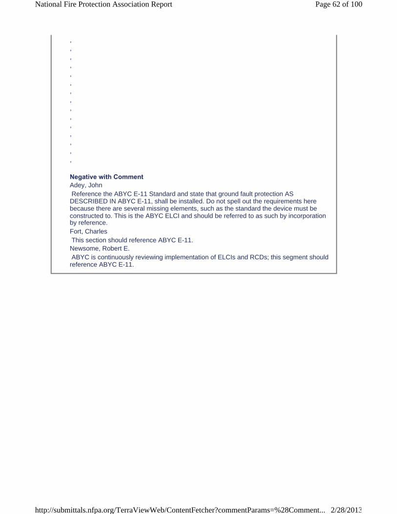
, , , , , , , , , , , , , , ,
Negative with CommentAdey, John Reference the ABYC E-11 Standard and state that ground fault protection AS DESCRIBED IN ABYC E-11, shall be installed. Do not spell out the requirements here because there are several missing elements, such as the standard the device must be constructed to. This is the ABYC ELCI and should be referred to as such by incorporation by reference.Fort, Charles This section should reference ABYC E-11.Newsome, Robert E. ABYC is continuously reviewing implementation of ELCIs and RCDs; this segment shouldreference ABYC E-11.
Page 62 of 100National Fire Protection Association Report
2/28/2013http://submittals.nfpa.org/TerraViewWeb/ContentFetcher?commentParams=%28Comment...

First Revision No. 30-NFPA 302-2012 [ New Section after 12.1.3.6.1 ]
Global FR-30 Hide Deleted
12.1.3.6.2Fixed fire-extinguishing systems shall be installed as high as practical in the engine space and as far from natural and powered ventilation as possible.
Submitter Information Verification
Submitter Full Name: [ Not Specified ]
Organization: [ Not Specified ]
Submittal Date: Tue Aug 28 14:33:34 EDT 2012
Committee Statement and Meeting Notes
CommitteeStatement:
Moved the recommended change from PI 27 to this section of the Standard.
Response Message:
Ballot Results
This item has passed ballot
24 Eligible Voters
5 Not Returned
18 Affirmative All
0 Affirmative with Comments
1 Negative with Comments
0 Abstention
Not ReturnedChiasson, RussellColavecchio, William A. Game, E. C.LeBlanc, David J. Montgomery, Larry
Affirmative All, , , , , , , ,
Page 63 of 100National Fire Protection Association Report
2/28/2013http://submittals.nfpa.org/TerraViewWeb/ContentFetcher?commentParams=%28Comment...

, , , , , , , , , ,
Negative with CommentMcFarlin, David No scientific study was done to support this change.
Page 64 of 100National Fire Protection Association Report
2/28/2013http://submittals.nfpa.org/TerraViewWeb/ContentFetcher?commentParams=%28Comment...

First Revision No. 29-NFPA 302-2012 [ Section No. 12.1.3.6.2 ]
12.1.3.6.3*Manual controls shall be located to be readily accessible from outside the spaces served by the systems.
Submitter Information Verification
Submitter Full Name: [ Not Specified ]
Organization: [ Not Specified ]
Submittal Date: Tue Aug 28 14:32:40 EDT 2012
Committee Statement and Meeting Notes
Committee Statement: Reorganization of requirement.
Response Message:
Ballot Results
This item has passed ballot
24 Eligible Voters
5 Not Returned
19 Affirmative All
0 Affirmative with Comments
0 Negative with Comments
0 Abstention
Not ReturnedChiasson, RussellColavecchio, William A. Game, E. C.LeBlanc, David J. Montgomery, Larry
Affirmative All, , , , , , , , , ,
Page 65 of 100National Fire Protection Association Report
2/28/2013http://submittals.nfpa.org/TerraViewWeb/ContentFetcher?commentParams=%28Comment...

, , , , , , , , ,
Page 66 of 100National Fire Protection Association Report
2/28/2013http://submittals.nfpa.org/TerraViewWeb/ContentFetcher?commentParams=%28Comment...
First Revision No. 28-NFPA 302-2012 [ Section No. 12.1.3.6.3 ]
12.1.3.6.4Systems shall be designed for one of the following modes of application:
(1) An independent system installed to cover one of various unconnected protected spaces
(2) A single system of sufficient capacity to flood all protected spaces simultaneously
(3) A single system of sufficient capacity for the largest protected space, distributed to the selected space by valves at the controls
Submitter Information Verification
Submitter Full Name: [ Not Specified ]
Organization: [ Not Specified ]
Submittal Date: Tue Aug 28 14:31:50 EDT 2012
Committee Statement and Meeting Notes
Committee Statement: Reorganization of requirement.
Response Message:
Ballot Results
This item has passed ballot
24 Eligible Voters
5 Not Returned
19 Affirmative All
0 Affirmative with Comments
0 Negative with Comments
0 Abstention
Not ReturnedChiasson, RussellColavecchio, William A. Game, E. C.LeBlanc, David J. Montgomery, Larry
Affirmative All, , , ,
Page 67 of 100National Fire Protection Association Report
2/28/2013http://submittals.nfpa.org/TerraViewWeb/ContentFetcher?commentParams=%28Comment...
, , , , , , , , , , , , , , ,
Page 68 of 100National Fire Protection Association Report
2/28/2013http://submittals.nfpa.org/TerraViewWeb/ContentFetcher?commentParams=%28Comment...
First Revision No. 34-NFPA 302-2012 [ Section No. 12.2 ]
12.2* Smoke Detection.All vessels 26 ft (8 m) or more in length with accommodation spaces intended for sleeping shall be equipped with a single-station smoke alarm that is listed to ANSI/UL 217, Standard for Single and Multiple Station Smoke Alarms , for marine or recreational vehicle use and is installed and maintained according to the device manufacturer's instructions.
Submitter Information Verification
Submitter Full Name: [ Not Specified ]
Organization: [ Not Specified ]
Submittal Date: Tue Aug 28 15:04:26 EDT 2012
Committee Statement and Meeting Notes
CommitteeStatement:
This requirement is moved to new section 13.3 in its entirety. See revision related to PI 8.
Response Message:
Ballot Results
This item has passed ballot
24 Eligible Voters
5 Not Returned
19 Affirmative All
0 Affirmative with Comments
0 Negative with Comments
0 Abstention
Not ReturnedChiasson, RussellColavecchio, William A. Game, E. C.LeBlanc, David J. Montgomery, Larry
Affirmative All, , , , , ,
Page 69 of 100National Fire Protection Association Report
2/28/2013http://submittals.nfpa.org/TerraViewWeb/ContentFetcher?commentParams=%28Comment...

, , , , , , , , , , , , ,
Page 70 of 100National Fire Protection Association Report
2/28/2013http://submittals.nfpa.org/TerraViewWeb/ContentFetcher?commentParams=%28Comment...

First Revision No. 33-NFPA 302-2012 [ Section No. 13.1 ]
13.1* Carbon Monoxide and Smoke Detection Systems.A carbon monoxide detection system shall be installed on all boats with an enclosed accommodation compartment(s) and a gasoline generator set, or an inboard gasoline propulsion engine.
Submitter Information Verification
Submitter Full Name: [ Not Specified ]
Organization: [ Not Specified ]
Submittal Date: Tue Aug 28 15:01:44 EDT 2012
Committee Statement and Meeting Notes
CommitteeStatement:
The Committee took the public input from PI 8 and made a separate FR.
Response Message:
Ballot Results
This item has passed ballot
24 Eligible Voters
5 Not Returned
19 Affirmative All
0 Affirmative with Comments
0 Negative with Comments
0 Abstention
Not ReturnedChiasson, RussellColavecchio, William A. Game, E. C.LeBlanc, David J. Montgomery, Larry
Affirmative All, , , , , , , , ,
Page 71 of 100National Fire Protection Association Report
2/28/2013http://submittals.nfpa.org/TerraViewWeb/ContentFetcher?commentParams=%28Comment...

, , , , , , , , , ,
Page 72 of 100National Fire Protection Association Report
2/28/2013http://submittals.nfpa.org/TerraViewWeb/ContentFetcher?commentParams=%28Comment...
First Revision No. 35-NFPA 302-2012 [ New Section after 13.2 ]
13.3* Smoke Detection. All vessels with accommodation spaces intended for sleeping shall be equipped with a single-station smoke alarm that is listed to ANSI/UL 217, Standard for Single and Multiple Station Smoke Alarms , for marine or recreational vehicle use and is installed and maintained according to the device manufacturer'sinstructions.
Submitter Information Verification
Submitter Full Name: [ Not Specified ]
Organization: [ Not Specified ]
Submittal Date: Tue Aug 28 15:05:24 EDT 2012
Committee Statement and Meeting Notes
CommitteeStatement:
Moved requirement from 12.2 to this chapter in accord with PI 8. The Committee removed the requirement for vessels 26 ft or more in length because there are smaller vessels that have accommodation spaces and need to be included in the requirement.
Response Message:
Ballot Results
This item has passed ballot
24 Eligible Voters
5 Not Returned
19 Affirmative All
0 Affirmative with Comments
0 Negative with Comments
0 Abstention
Not ReturnedChiasson, RussellColavecchio, William A. Game, E. C.LeBlanc, David J. Montgomery, Larry
Affirmative All, , , ,
Page 73 of 100National Fire Protection Association Report
2/28/2013http://submittals.nfpa.org/TerraViewWeb/ContentFetcher?commentParams=%28Comment...

, , , , , , , , , , , , , , ,
Page 74 of 100National Fire Protection Association Report
2/28/2013http://submittals.nfpa.org/TerraViewWeb/ContentFetcher?commentParams=%28Comment...

First Revision No. 41-NFPA 302-2012 [ Section No. A.1.6 ]
A.1.6For additional conversion information, see ASTM SI 10, Standard for Use of the International System of Units (SI): The Modern Metric System IEEE/ASTM SI 10, American National Standard for Use of the International System of Units (SI): The Modern Metric SystemMetric Practice , 2010 edition .
Submitter Information Verification
Submitter Full Name: [ Not Specified ]
Organization: [ Not Specified ]
Submittal Date: Wed Aug 29 10:48:40 EDT 2012
Committee Statement and Meeting Notes
Committee Statement: Title and revision date of the referenced document is updated.
Response Message:
Ballot Results
This item has passed ballot
24 Eligible Voters
5 Not Returned
19 Affirmative All
0 Affirmative with Comments
0 Negative with Comments
0 Abstention
Not ReturnedChiasson, RussellColavecchio, William A. Game, E. C.LeBlanc, David J. Montgomery, Larry
Affirmative All, , , , , , , , ,
Page 75 of 100National Fire Protection Association Report
2/28/2013http://submittals.nfpa.org/TerraViewWeb/ContentFetcher?commentParams=%28Comment...

, , , , , , , , , ,
Page 76 of 100National Fire Protection Association Report
2/28/2013http://submittals.nfpa.org/TerraViewWeb/ContentFetcher?commentParams=%28Comment...

First Revision No. 52-NFPA 302-2012 [ Section No. A.5.8 ]
A.5.8See SAE J1191, Recommended Practice for High Tension Ignition Cable Assemblies—Marine.
Submitter Information Verification
Submitter Full Name: [ Not Specified ]
Organization: [ Not Specified ]
Submittal Date: Wed Aug 29 13:25:53 EDT 2012
Committee Statement and Meeting Notes
Committee Statement: Updated title of referenced document.
Response Message:
Ballot Results
This item has passed ballot
24 Eligible Voters
5 Not Returned
19 Affirmative All
0 Affirmative with Comments
0 Negative with Comments
0 Abstention
Not ReturnedChiasson, RussellColavecchio, William A. Game, E. C. GameLeBlanc, David J.Montgomery, Larry
Affirmative All, , , , , , , , , ,
Page 77 of 100National Fire Protection Association Report
2/28/2013http://submittals.nfpa.org/TerraViewWeb/ContentFetcher?commentParams=%28Comment...
, , , , , , , , ,
Page 78 of 100National Fire Protection Association Report
2/28/2013http://submittals.nfpa.org/TerraViewWeb/ContentFetcher?commentParams=%28Comment...

First Revision No. 23-NFPA 302-2012 [ New Section after A.8.5.15.6 ]
A.9ABYC E-11, AC & DC Electrical Systems on Boats , can be used to meet the requirements of this chapter.
Submitter Information Verification
Submitter Full Name: [ Not Specified ]
Organization: [ Not Specified ]
Submittal Date: Tue Aug 28 13:46:19 EDT 2012
Committee Statement and Meeting Notes
CommitteeStatement:
The Committee recognizes that ABYC E-11 is updated frequently. The Committee added a reference to ABYC E-11 to allow the user to have access to additional information on electrical system standards.
ResponseMessage:
Ballot Results
This item has passed ballot
24 Eligible Voters
5 Not Returned
19 Affirmative All
0 Affirmative with Comments
0 Negative with Comments
0 Abstention
Not ReturnedChiasson, RussellColavecchio, William A. Game, E. C.LeBlanc, David J. Montgomery, Larry
Affirmative All, , , , , , , ,
Page 79 of 100National Fire Protection Association Report
2/28/2013http://submittals.nfpa.org/TerraViewWeb/ContentFetcher?commentParams=%28Comment...

, , , , , , , , , , ,
Page 80 of 100National Fire Protection Association Report
2/28/2013http://submittals.nfpa.org/TerraViewWeb/ContentFetcher?commentParams=%28Comment...
First Revision No. 53-NFPA 302-2012 [ Section No. A.9.12.2 ]
A.9.12.2For information on marine engine wiring, see SAE J378, Recommended Practice for Marine Engine Propulsion System Wiring.
Submitter Information Verification
Submitter Full Name: [ Not Specified ]
Organization: [ Not Specified ]
Submittal Date: Wed Aug 29 13:29:06 EDT 2012
Committee Statement and Meeting Notes
Committee Statement: Updated title of the referenced document.
Response Message:
Ballot Results
This item has passed ballot
24 Eligible Voters
5 Not Returned
19 Affirmative All
0 Affirmative with Comments
0 Negative with Comments
0 Abstention
Not ReturnedChiasson, RussellColavecchio, William A. Game, E. C.LeBlanc, David J. Montgomery, Larry
Affirmative All, , , , , , , , , ,
Page 81 of 100National Fire Protection Association Report
2/28/2013http://submittals.nfpa.org/TerraViewWeb/ContentFetcher?commentParams=%28Comment...

, , , , , , , , ,
Page 82 of 100National Fire Protection Association Report
2/28/2013http://submittals.nfpa.org/TerraViewWeb/ContentFetcher?commentParams=%28Comment...
First Revision No. 24-NFPA 302-2012 [ New Section after A.9.14.7 ]
A.10ABYC E-11, AC & DC Electrical Systems on Boats , can be used to meet the requirements of this chapter.
Submitter Information Verification
Submitter Full Name: [ Not Specified ]
Organization: [ Not Specified ]
Submittal Date: Tue Aug 28 13:52:59 EDT 2012
Committee Statement and Meeting Notes
CommitteeStatement:
The Committee recognizes that ABYC E-11 is updated frequently. The Committee added a reference to ABYC E-11 to allow the user to have access to additional information on electrical system standards.
ResponseMessage:
Ballot Results
This item has passed ballot
24 Eligible Voters
5 Not Returned
19 Affirmative All
0 Affirmative with Comments
0 Negative with Comments
0 Abstention
Not ReturnedChiasson, RussellColavecchio, William A. Game, E. C.LeBlanc, David J. Montgomery, Larry
Affirmative All, , , , , , , ,
Page 83 of 100National Fire Protection Association Report
2/28/2013http://submittals.nfpa.org/TerraViewWeb/ContentFetcher?commentParams=%28Comment...

, , , , , , , , , , ,
Page 84 of 100National Fire Protection Association Report
2/28/2013http://submittals.nfpa.org/TerraViewWeb/ContentFetcher?commentParams=%28Comment...
First Revision No. 42-NFPA 302-2012 [ Section No. A.10.15.7 ]
A.10.15.7See NFPA 70® , National Electrical Code® ; , E-8.12 of ABYC E-8 , AlternatingCurrent (AC) Electrical Systems on Boats ABYC E-11, AC & DC Electrical Systems on Boats ; , and applicable UL standards, for additional information.
Submitter Information Verification
Submitter Full Name: [ Not Specified ]
Organization: [ Not Specified ]
Submittal Date: Wed Aug 29 11:09:49 EDT 2012
Committee Statement and Meeting Notes
CommitteeStatement:
ABYC E-8 was Alternating Current (AC) Electrical Systems on Boats was incorporated into ABYC E-11 in July 2003.
Response Message:
Ballot Results
This item has passed ballot
24 Eligible Voters
5 Not Returned
19 Affirmative All
0 Affirmative with Comments
0 Negative with Comments
0 Abstention
Not ReturnedChiasson, RussellColavecchio, William A. Game, E. C.LeBlanc, David J. Montgomery, Larry
Affirmative All, , , , , , ,
Page 85 of 100National Fire Protection Association Report
2/28/2013http://submittals.nfpa.org/TerraViewWeb/ContentFetcher?commentParams=%28Comment...
, , , , , , , , , , , ,
Page 86 of 100National Fire Protection Association Report
2/28/2013http://submittals.nfpa.org/TerraViewWeb/ContentFetcher?commentParams=%28Comment...

First Revision No. 36-NFPA 302-2012 [ Section No. A.12.2 ]
A.13.3It is recommended on commercial vessels 12 m and larger that engine room firedetection equipment be installed with notification capability at the helm.
Engine room fire suppression is not a substitute for engine room fire detection. Occupants of most vessels 12 m and larger are typically too far from the engine room to detect a fire without the assistance of properly installed detection equipment. The occupants of the vessel can be placed in further peril when it becomes necessary to escape the fire by entering the water. Engine room fires need to be detected early in order to reduce the dangers to the vessel's occupants and damage to the vessel. Heat and/or smoke alarms should be listed to appropriate standards for the device and installed according to the device manufacturer’s instructions.
Submitter Information Verification
Submitter Full Name: [ Not Specified ]
Organization: [ Not Specified ]
Submittal Date: Tue Aug 28 15:11:54 EDT 2012
Committee Statement and Meeting Notes
CommitteeStatement:
Changed designation of requirement in accord with the change made in FR 35 for new requirement 13.3.
Response Message:
Ballot Results
This item has passed ballot
24 Eligible Voters
5 Not Returned
19 Affirmative All
0 Affirmative with Comments
0 Negative with Comments
0 Abstention
Not ReturnedChiasson, RussellColavecchio, William A. Game, E. C.LeBlanc, David J. Montgomery, Larry
Affirmative All
Page 87 of 100National Fire Protection Association Report
2/28/2013http://submittals.nfpa.org/TerraViewWeb/ContentFetcher?commentParams=%28Comment...

, , , , , , , , , , , , , , , , , , ,
Page 88 of 100National Fire Protection Association Report
2/28/2013http://submittals.nfpa.org/TerraViewWeb/ContentFetcher?commentParams=%28Comment...
First Revision No. 39-NFPA 302-2012 [ Section No. F.1.1 ]
F.1.1 NFPA Publications.National Fire Protection Association, 1 Batterymarch Park, Quincy, MA 02169-7471.
NFPA 10, Standard for Portable Fire Extinguishers, 2007 2010 edition.
NFPA 58, Liquefied Petroleum Gas Code, 2008 2011 edition.
NFPA 70®, National Electrical Code®, 2008 2011 edition.
NFPA 72®, National Fire Alarm and Signaling Code, 2010 edition.
NFPA 2001, Standard on Clean Agent Fire Extinguishing Systems, 2008 2012edition.
Submitter Information Verification
Submitter Full Name: [ Not Specified ]
Organization: [ Not Specified ]
Submittal Date: Wed Aug 29 10:37:38 EDT 2012
Committee Statement and Meeting Notes
Committee Statement: The revision dates of these documents are updated.
Response Message:
Ballot Results
This item has passed ballot
24 Eligible Voters
5 Not Returned
18 Affirmative All
1 Affirmative with Comments
0 Negative with Comments
0 Abstention
Not ReturnedChiasson, RussellColavecchio, William A. Game, E. C.LeBlanc, David J. Montgomery, Larry
Affirmative All, ,
Page 89 of 100National Fire Protection Association Report
2/28/2013http://submittals.nfpa.org/TerraViewWeb/ContentFetcher?commentParams=%28Comment...
, , , , , , , , , , , , , , , ,
Affirmative with CommentMcFarlin, David Although voting affirmative, I think more study needs to be done relative to the new edition standards and how they may have an affect on 302.
Page 90 of 100National Fire Protection Association Report
2/28/2013http://submittals.nfpa.org/TerraViewWeb/ContentFetcher?commentParams=%28Comment...
First Revision No. 38-NFPA 302-2012 [ Section No. F.1.2.1 ]
F.1.2.1 ABYC Publications.American Boat & Yacht Council, Inc., 613 Third Street, Suite 10, Annapolis, MD 21403.
ABYC A-4, Fire Fighting Equipment, 2002 2008 .
ABYC E-11, AC & DC Electrical Systems on Boats , 2012 .
ABYC TH-22, Educational Information About Carbon Monoxide, 2002 2012 .
ABYC TH-23, Design, Construction, and Testing of Boats in Consideration of Carbon Monoxide, 2004 2012 .
Submitter Information Verification
Submitter Full Name: [ Not Specified ]
Organization: [ Not Specified ]
Submittal Date: Wed Aug 29 10:33:32 EDT 2012
Committee Statement and Meeting Notes
CommitteeStatement:
The Committee has updated the referenced standards to most recent edition and added missing referenced documents as indicated.
ResponseMessage:Public Input No. 25-NFPA 302-2012 [Section No. F.1.2.1]
Ballot Results
This item has passed ballot
24 Eligible Voters
5 Not Returned
18 Affirmative All
1 Affirmative with Comments
0 Negative with Comments
0 Abstention
Not ReturnedChiasson, RussellColavecchio, William A. Game, E. C.LeBlanc, David J. Montgomery, Larry
Affirmative All,
Page 91 of 100National Fire Protection Association Report
2/28/2013http://submittals.nfpa.org/TerraViewWeb/ContentFetcher?commentParams=%28Comment...
, , , , , , , , , , , , , , , , ,
Affirmative with CommentMcFarlin, David Although voting affirmative, I think more study needs to be done relative to the new edition standards and how they may have an affect on 302.
Page 92 of 100National Fire Protection Association Report
2/28/2013http://submittals.nfpa.org/TerraViewWeb/ContentFetcher?commentParams=%28Comment...
First Revision No. 40-NFPA 302-2012 [ Section No. F.1.2.2 ]
F.1.2.2 ASTM Publication.ASTM International, 100 Barr Harbor Drive, P.O. Box C700, West Conshohocken, PA 19428-2959.
IEEE/ASTM SI 10, Standard for Use of the International System of Units (SI): The Modern Metric System American National Standard for Metric Practice , 2002 2010edition.
Submitter Information Verification
Submitter Full Name: [ Not Specified ]
Organization: [ Not Specified ]
Submittal Date: Wed Aug 29 10:41:59 EDT 2012
Committee Statement and Meeting Notes
Committee Statement: The title and revision date of the document is updated.
Response Message:
Ballot Results
This item has passed ballot
24 Eligible Voters
5 Not Returned
18 Affirmative All
1 Affirmative with Comments
0 Negative with Comments
0 Abstention
Not ReturnedChiasson, RussellColavecchio, William A. Game, E. C.LeBlanc, David J.Montgomery, Larry
Affirmative All, , , , , , ,
Page 93 of 100National Fire Protection Association Report
2/28/2013http://submittals.nfpa.org/TerraViewWeb/ContentFetcher?commentParams=%28Comment...

, , , , , , , , , , ,
Affirmative with CommentMcFarlin, David Although voting affirmative, I think more study needs to be done relative to the new edition standards and how they may have an affect on 302.
Page 94 of 100National Fire Protection Association Report
2/28/2013http://submittals.nfpa.org/TerraViewWeb/ContentFetcher?commentParams=%28Comment...

First Revision No. 43-NFPA 302-2012 [ Section No. F.1.2.4 ]
F.1.2.4 SAE Publications.Society of Automotive Engineers, 400 Commonwealth Drive, Warrendale, PA 15096.
SAE J378, Recommended Practice for Marine Engine Propulsion System Wiring, 2004 2011 .
SAE J1171, Recommended Practice for External Ignition Protection of Marine Electrical Devices, 2004 2011 .
SAE J1191, Recommended Practice for High Tension Ignition Cable Assemblies—Marine, 2005 2011 .
SAE J1223, Recommended Practice for Marine Carburetors and Fuel Injection Throttle Bodies, 2006.
SAE J1294, Recommended Practice for Ignition Distributors—Marine, 2004 2010 .
SAE J1428, Recommended Practice for Marine Circuit Breakers, 2006.
Submitter Information Verification
Submitter Full Name: [ Not Specified ]
Organization: [ Not Specified ]
Submittal Date: Wed Aug 29 11:16:22 EDT 2012
Committee Statement and Meeting Notes
Committee Statement: Revision dates and titles of referenced publications are updated.
Response Message:
Ballot Results
This item has passed ballot
24 Eligible Voters
5 Not Returned
18 Affirmative All
1 Affirmative with Comments
0 Negative with Comments
0 Abstention
Not ReturnedChiasson, RussellColavecchio, William A. Game, E. C.LeBlanc, David J. Montgomery, Larry
Page 95 of 100National Fire Protection Association Report
2/28/2013http://submittals.nfpa.org/TerraViewWeb/ContentFetcher?commentParams=%28Comment...

Affirmative All, , , , , , , , , , , , , , , , , ,
Affirmative with CommentMcFarlin, David Although voting affirmative, I think more study needs to be done relative to the new edition standards and how they may have an affect on 302.
Page 96 of 100National Fire Protection Association Report
2/28/2013http://submittals.nfpa.org/TerraViewWeb/ContentFetcher?commentParams=%28Comment...

First Revision No. 45-NFPA 302-2012 [ Section No. F.1.2.5 ]
F.1.2.5 UL Publications.Underwriters Laboratories Inc., 333 Pfingsten Road, Northbrook, IL 60062-2096.
ANSI/UL 217, Standard for Single and Multiple Station Smoke Alarms, 2006, Revised May 2007 2011 .
ANSI/UL 268, Smoke Detectors for Fire Protective Signaling Systems, 2006 2009 .
ANSI/UL 1971, Standard for Signaling Devices for Hearing Impaired, 2002, Revised May 2006 2008 .
Submitter Information Verification
Submitter Full Name: [ Not Specified ]
Organization: [ Not Specified ]
Submittal Date: Wed Aug 29 11:36:04 EDT 2012
Committee Statement and Meeting Notes
CommitteeStatement:
The Committee has updated the referenced standards to most recent edition as indicated.
Response Message:Public Input No. 2-NFPA 302-2012 [Section No. F.1.2.5]
Ballot Results
This item has passed ballot
24 Eligible Voters
5 Not Returned
18 Affirmative All
1 Affirmative with Comments
0 Negative with Comments
0 Abstention
Not ReturnedChiasson, RussellColavecchio, William A. Game, E. C.LeBlanc, David J. Montgomery, Larry
Affirmative All, , ,
Page 97 of 100National Fire Protection Association Report
2/28/2013http://submittals.nfpa.org/TerraViewWeb/ContentFetcher?commentParams=%28Comment...

, , , , , , , , , , , , , , ,
Affirmative with CommentMcFarlin, David Although voting affirmative, I think more study needs to be done relative to the new edition standards and how they may have an affect on 302.
Page 98 of 100National Fire Protection Association Report
2/28/2013http://submittals.nfpa.org/TerraViewWeb/ContentFetcher?commentParams=%28Comment...
First Revision No. 44-NFPA 302-2012 [ Section No. F.3 ]
F.3 References for Extracts in Informational Sections. NFPA 10, Standard for Portable Fire Extinguishers,2002 2010 edition.
NFPA 12, Standard on Carbon Dioxide Extinguishing Systems,2000 2011 edition.
NFPA 12A, Standard on Halon 1301 Fire Extinguishing Systems,2001 2009edition.
NFPA 2001, Standard on Clean Agent Fire Extinguishing Systems,2000 2012edition.
Submitter Information Verification
Submitter Full Name: [ Not Specified ]
Organization: [ Not Specified ]
Submittal Date: Wed Aug 29 11:33:28 EDT 2012
Committee Statement and Meeting Notes
Committee Statement: Updated the edition dates of NFPA documents used for extracts.
Response Message:
Ballot Results
This item has passed ballot
24 Eligible Voters
5 Not Returned
19 Affirmative All
0 Affirmative with Comments
0 Negative with Comments
0 Abstention
Not ReturnedChiasson, RussellColavecchio, William A. Game, E. C.LeBlanc, David J.Montgomery, Larry
Affirmative All, , , , ,
Page 99 of 100National Fire Protection Association Report
2/28/2013http://submittals.nfpa.org/TerraViewWeb/ContentFetcher?commentParams=%28Comment...

, , , , , , , , , , , , , ,
Page 100 of 100National Fire Protection Association Report
2/28/2013http://submittals.nfpa.org/TerraViewWeb/ContentFetcher?commentParams=%28Comment...
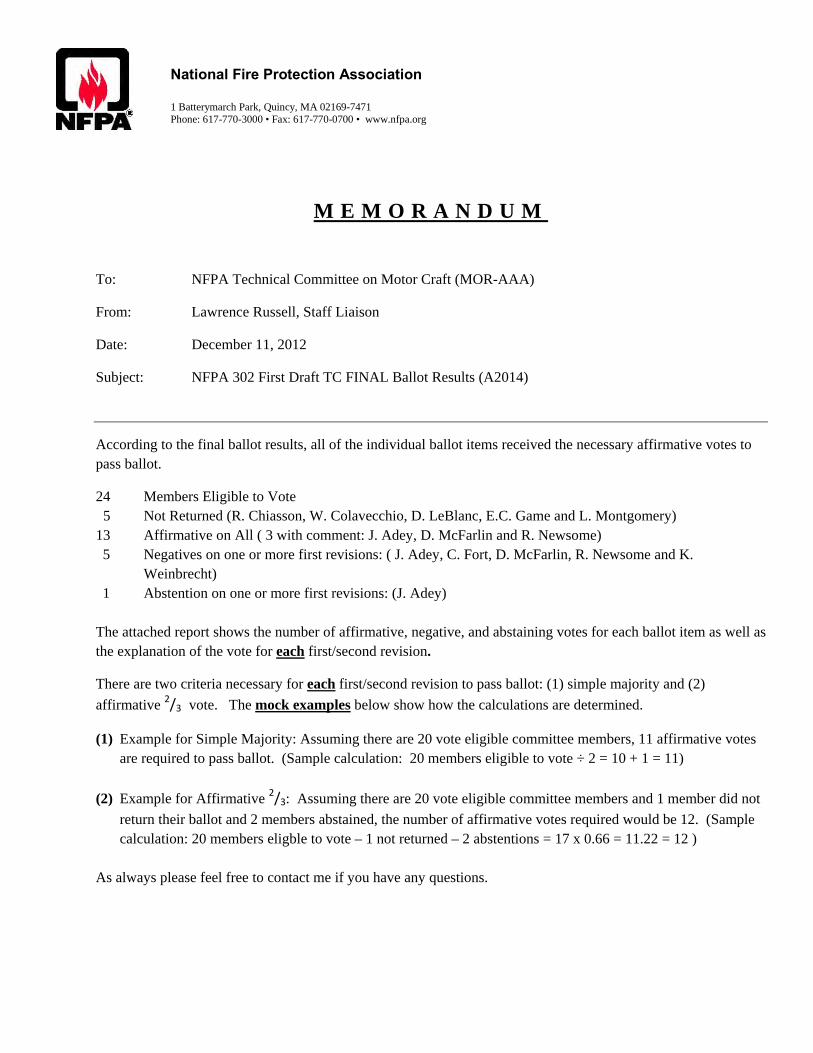
National Fire Protection Association 1 Batterymarch Park, Quincy, MA 02169-7471 Phone: 617-770-3000 • Fax: 617-770-0700 • www.nfpa.org
M E M O R A N D U M
To: NFPA Technical Committee on Motor Craft (MOR-AAA)
From: Lawrence Russell, Staff Liaison
Date: December 11, 2012
Subject: NFPA 302 First Draft TC FINAL Ballot Results (A2014)
According to the final ballot results, all of the individual ballot items received the necessary affirmative votes to pass ballot.
24 Members Eligible to Vote 5 Not Returned (R. Chiasson, W. Colavecchio, D. LeBlanc, E.C. Game and L. Montgomery) 13 Affirmative on All ( 3 with comment: J. Adey, D. McFarlin and R. Newsome) 5 Negatives on one or more first revisions: ( J. Adey, C. Fort, D. McFarlin, R. Newsome and K.
Weinbrecht) 1 Abstention on one or more first revisions: (J. Adey) The attached report shows the number of affirmative, negative, and abstaining votes for each ballot item as well as the explanation of the vote for each first/second revision.
There are two criteria necessary for each first/second revision to pass ballot: (1) simple majority and (2)
affirmative 2/3 vote. The mock examples below show how the calculations are determined.
(1) Example for Simple Majority: Assuming there are 20 vote eligible committee members, 11 affirmative votes are required to pass ballot. (Sample calculation: 20 members eligible to vote ÷ 2 = 10 + 1 = 11)
(2) Example for Affirmative 2/3: Assuming there are 20 vote eligible committee members and 1 member did not
return their ballot and 2 members abstained, the number of affirmative votes required would be 12. (Sample calculation: 20 members eligble to vote – 1 not returned – 2 abstentions = 17 x 0.66 = 11.22 = 12 )
As always please feel free to contact me if you have any questions.

Results by Question
FR-56, Global Input, See FR-56Total Voters: 24 Ballots Not Returned: 5
Choice Votes CommentsAffirmative with Comment 1John Adey AffirmNegative 0Abstain 0Affirmative 18For two-third majority election, the affirmative votes needed are 13
For Simple majority, the affirmative votes needed are 13
FR-18, Section No. 2.2, See FR-18Total Voters: 24 Ballots Not Returned: 5
Choice Votes CommentsAffirmative with Comment 2John Adey AffirmDavid McFarlin Although voting affirmative I think more study
needs to be done relative to the new edition standards and how they may have an affect on 302.
Negative 0Abstain 0Affirmative 17For two-third majority election, the affirmative votes needed are 13
For Simple majority, the affirmative votes needed are 13
NFPA 302 First Draft Ballot Results
Page 1 of 23
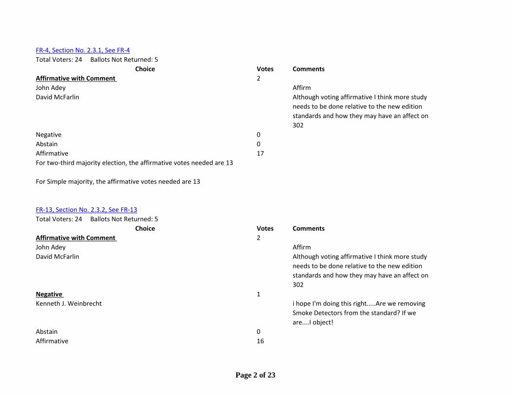
FR-4, Section No. 2.3.1, See FR-4Total Voters: 24 Ballots Not Returned: 5
Choice Votes CommentsAffirmative with Comment 2John Adey AffirmDavid McFarlin Although voting affirmative I think more study
needs to be done relative to the new edition standards and how they may have an affect on 302
Negative 0Abstain 0Affirmative 17For two-third majority election, the affirmative votes needed are 13
For Simple majority, the affirmative votes needed are 13
FR-13, Section No. 2.3.2, See FR-13Total Voters: 24 Ballots Not Returned: 5
Choice Votes CommentsAffirmative with Comment 2John Adey AffirmDavid McFarlin Although voting affirmative I think more study
needs to be done relative to the new edition standards and how they may have an affect on 302
Negative 1Kenneth J. Weinbrecht i hope I'm doing this right.....Are we removing
Smoke Detectors from the standard? If we are....I object!
Abstain 0Affirmative 16
Page 2 of 23
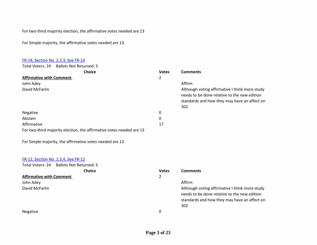
For two-third majority election, the affirmative votes needed are 13
For Simple majority, the affirmative votes needed are 13
FR-14, Section No. 2.3.3, See FR-14Total Voters: 24 Ballots Not Returned: 5
Choice Votes CommentsAffirmative with Comment 2John Adey AffirmDavid McFarlin Although voting affirmative I think more study
needs to be done relative to the new edition standards and how they may have an affect on 302
Negative 0Abstain 0Affirmative 17For two-third majority election, the affirmative votes needed are 13
For Simple majority, the affirmative votes needed are 13
FR-12, Section No. 2.3.4, See FR-12Total Voters: 24 Ballots Not Returned: 5
Choice Votes CommentsAffirmative with Comment 2John Adey AffirmDavid McFarlin Although voting affirmative I think more study
needs to be done relative to the new edition standards and how they may have an affect on 302
Negative 0
Page 3 of 23

Abstain 0Affirmative 17For two-third majority election, the affirmative votes needed are 13
For Simple majority, the affirmative votes needed are 13
FR-15, Section No. 2.3.5, See FR-15Total Voters: 24 Ballots Not Returned: 5
Choice Votes CommentsAffirmative with Comment 2John Adey AffirmDavid McFarlin Although voting affirmative I think more study
needs to be done relative to the new edition standards and how they may have an affect on 302
Negative 0Abstain 0Affirmative 17For two-third majority election, the affirmative votes needed are 13
For Simple majority, the affirmative votes needed are 13
FR-16, Section No. 2.3.6, See FR-16Total Voters: 24 Ballots Not Returned: 5
Choice Votes CommentsAffirmative with Comment 2John Adey Affirm
Page 4 of 23

David McFarlin Although voting affirmative I think more study needs to be done relative to the new edition standards and how they may have an affect on 302
Negative 0Abstain 0Affirmative 17For two-third majority election, the affirmative votes needed are 13
For Simple majority, the affirmative votes needed are 13
FR-2, Section No. 2.3.7, See FR-2Total Voters: 24 Ballots Not Returned: 5
Choice Votes CommentsAffirmative with Comment 2John Adey AffirmDavid McFarlin Although voting affirmative I think more study
needs to be done relative to the new edition standards and how they may have an affect on 302
Negative 0Abstain 0Affirmative 17For two-third majority election, the affirmative votes needed are 13
For Simple majority, the affirmative votes needed are 13
Page 5 of 23
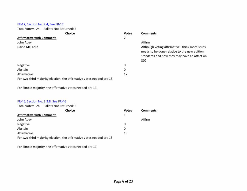
FR-17, Section No. 2.4, See FR-17Total Voters: 24 Ballots Not Returned: 5
Choice Votes CommentsAffirmative with Comment 2John Adey AffirmDavid McFarlin Although voting affirmative I think more study
needs to be done relative to the new edition standards and how they may have an affect on 302
Negative 0Abstain 0Affirmative 17For two-third majority election, the affirmative votes needed are 13
For Simple majority, the affirmative votes needed are 13
FR-46, Section No. 3.3.8, See FR-46Total Voters: 24 Ballots Not Returned: 5
Choice Votes CommentsAffirmative with Comment 1John Adey AffirmNegative 0Abstain 0Affirmative 18For two-third majority election, the affirmative votes needed are 13
For Simple majority, the affirmative votes needed are 13
Page 6 of 23

FR-3, Section No. 3.3.45, See FR-3Total Voters: 24 Ballots Not Returned: 5
Choice Votes CommentsAffirmative with Comment 1John Adey AffirmNegative 0Abstain 0Affirmative 18For two-third majority election, the affirmative votes needed are 13
For Simple majority, the affirmative votes needed are 13
FR-5, Section No. 4.1.6.1, See FR-5Total Voters: 24 Ballots Not Returned: 5
Choice Votes CommentsAffirmative with Comment 1John Adey AffirmNegative 0Abstain 0Affirmative 18For two-third majority election, the affirmative votes needed are 13
For Simple majority, the affirmative votes needed are 13
FR-6, Section No. 4.1.6.2, See FR-6Total Voters: 24 Ballots Not Returned: 5
Choice Votes CommentsAffirmative with Comment 1John Adey AffirmNegative 0
Page 7 of 23

Abstain 0Affirmative 18For two-third majority election, the affirmative votes needed are 13
For Simple majority, the affirmative votes needed are 13
FR-7, New Section after 4.5.1, See FR-7Total Voters: 24 Ballots Not Returned: 5
Choice Votes CommentsAffirmative with Comment 1John Adey AffirmNegative 0Abstain 0Affirmative 18For two-third majority election, the affirmative votes needed are 13
For Simple majority, the affirmative votes needed are 13
FR-48, Section No. 4.5.2.2, See FR-48Total Voters: 24 Ballots Not Returned: 5
Choice Votes CommentsAffirmative with Comment 1John Adey AffirmNegative 0Abstain 0Affirmative 18For two-third majority election, the affirmative votes needed are 13
For Simple majority, the affirmative votes needed are 13
Page 8 of 23
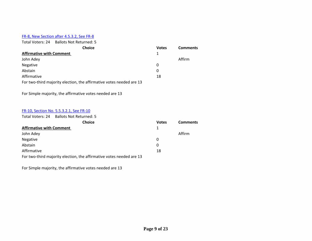
FR-8, New Section after 4.5.3.2, See FR-8Total Voters: 24 Ballots Not Returned: 5
Choice Votes CommentsAffirmative with Comment 1John Adey AffirmNegative 0Abstain 0Affirmative 18For two-third majority election, the affirmative votes needed are 13
For Simple majority, the affirmative votes needed are 13
FR-10, Section No. 5.5.3.2.1, See FR-10Total Voters: 24 Ballots Not Returned: 5
Choice Votes CommentsAffirmative with Comment 1John Adey AffirmNegative 0Abstain 0Affirmative 18For two-third majority election, the affirmative votes needed are 13
For Simple majority, the affirmative votes needed are 13
Page 9 of 23
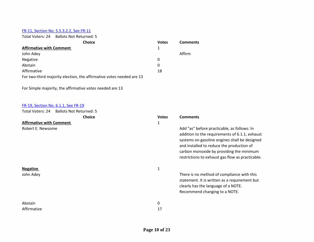
FR-11, Section No. 5.5.3.2.2, See FR-11Total Voters: 24 Ballots Not Returned: 5
Choice Votes CommentsAffirmative with Comment 1John Adey AffirmNegative 0Abstain 0Affirmative 18For two-third majority election, the affirmative votes needed are 13
For Simple majority, the affirmative votes needed are 13
FR-19, Section No. 6.1.1, See FR-19Total Voters: 24 Ballots Not Returned: 5
Choice Votes CommentsAffirmative with Comment 1Robert E. Newsome Add "as" before practicable, as follows: In
addition to the requirements of 6.1.1, exhaust systems on gasoline engines shall be designed and installed to reduce the production of carbon monoxide by providing the minimum restrictions to exhaust gas flow as practicable.
Negative 1John Adey There is no method of compliance with this
statement. It is written as a requirement but clearly has the language of a NOTE. Recommend changing to a NOTE.
Abstain 0Affirmative 17
Page 10 of 23
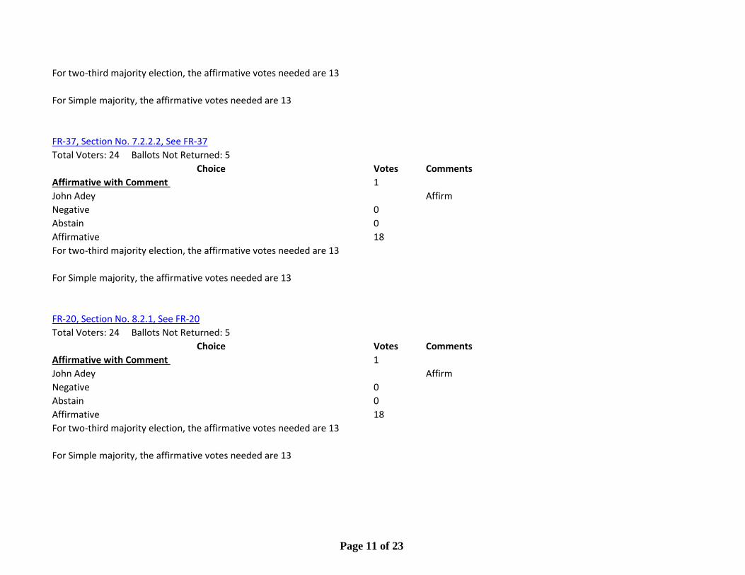
For two-third majority election, the affirmative votes needed are 13
For Simple majority, the affirmative votes needed are 13
FR-37, Section No. 7.2.2.2, See FR-37Total Voters: 24 Ballots Not Returned: 5
Choice Votes CommentsAffirmative with Comment 1John Adey AffirmNegative 0Abstain 0Affirmative 18For two-third majority election, the affirmative votes needed are 13
For Simple majority, the affirmative votes needed are 13
FR-20, Section No. 8.2.1, See FR-20Total Voters: 24 Ballots Not Returned: 5
Choice Votes CommentsAffirmative with Comment 1John Adey AffirmNegative 0Abstain 0Affirmative 18For two-third majority election, the affirmative votes needed are 13
For Simple majority, the affirmative votes needed are 13
Page 11 of 23

FR-22, Section No. 8.2.2, See FR-22Total Voters: 24 Ballots Not Returned: 5
Choice Votes CommentsAffirmative with Comment 0Negative 1John Adey This is a new requirement and may or may not
meet the criteria in ABYC A-3 Galley Stoves OR ISO 9094 Fire Protection. These documents are harmonized when it comes to zones and testing. Time is needed to research the compatibility of this newer standard with existing industry standards.
Abstain 0Affirmative 18For two-third majority election, the affirmative votes needed are 13
For Simple majority, the affirmative votes needed are 13
FR-54, Section No. 9.9.8, See FR-54Total Voters: 24 Ballots Not Returned: 5
Choice Votes CommentsAffirmative with Comment 1John Adey AffirmNegative 0Abstain 0Affirmative 18For two-third majority election, the affirmative votes needed are 13
For Simple majority, the affirmative votes needed are 13
Page 12 of 23
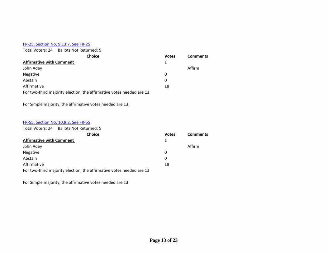
FR-25, Section No. 9.13.7, See FR-25Total Voters: 24 Ballots Not Returned: 5
Choice Votes CommentsAffirmative with Comment 1John Adey AffirmNegative 0Abstain 0Affirmative 18For two-third majority election, the affirmative votes needed are 13
For Simple majority, the affirmative votes needed are 13
FR-55, Section No. 10.8.2, See FR-55Total Voters: 24 Ballots Not Returned: 5
Choice Votes CommentsAffirmative with Comment 1John Adey AffirmNegative 0Abstain 0Affirmative 18For two-third majority election, the affirmative votes needed are 13
For Simple majority, the affirmative votes needed are 13
Page 13 of 23
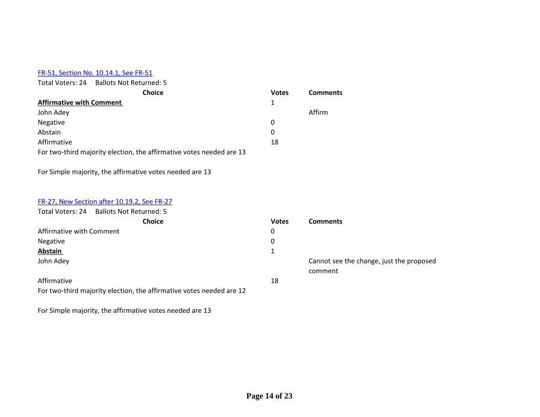
FR-51, Section No. 10.14.1, See FR-51Total Voters: 24 Ballots Not Returned: 5
Choice Votes CommentsAffirmative with Comment 1John Adey AffirmNegative 0Abstain 0Affirmative 18For two-third majority election, the affirmative votes needed are 13
For Simple majority, the affirmative votes needed are 13
FR-27, New Section after 10.19.2, See FR-27Total Voters: 24 Ballots Not Returned: 5
Choice Votes CommentsAffirmative with Comment 0Negative 0Abstain 1John Adey Cannot see the change, just the proposed
commentAffirmative 18For two-third majority election, the affirmative votes needed are 12
For Simple majority, the affirmative votes needed are 13
Page 14 of 23
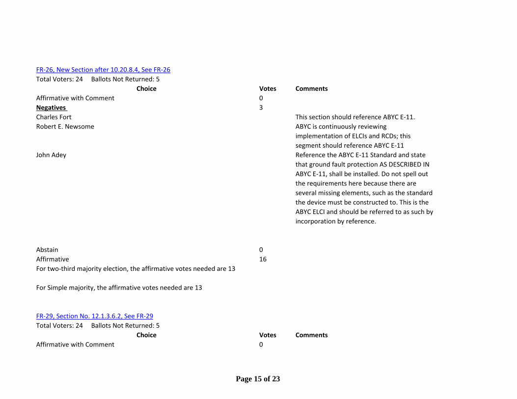
FR-26, New Section after 10.20.8.4, See FR-26Total Voters: 24 Ballots Not Returned: 5
Choice Votes CommentsAffirmative with Comment 0Negatives 3Charles Fort This section should reference ABYC E-11.Robert E. Newsome ABYC is continuously reviewing
implementation of ELCIs and RCDs; this segment should reference ABYC E-11
John Adey Reference the ABYC E-11 Standard and state that ground fault protection AS DESCRIBED IN ABYC E-11, shall be installed. Do not spell out the requirements here because there are several missing elements, such as the standard the device must be constructed to. This is the ABYC ELCI and should be referred to as such by incorporation by reference.
Abstain 0Affirmative 16For two-third majority election, the affirmative votes needed are 13
For Simple majority, the affirmative votes needed are 13
FR-29, Section No. 12.1.3.6.2, See FR-29Total Voters: 24 Ballots Not Returned: 5
Choice Votes CommentsAffirmative with Comment 0
Page 15 of 23
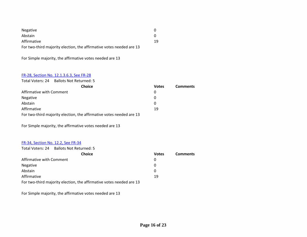
Negative 0Abstain 0Affirmative 19For two-third majority election, the affirmative votes needed are 13
For Simple majority, the affirmative votes needed are 13
FR-28, Section No. 12.1.3.6.3, See FR-28Total Voters: 24 Ballots Not Returned: 5
Choice Votes CommentsAffirmative with Comment 0Negative 0Abstain 0Affirmative 19For two-third majority election, the affirmative votes needed are 13
For Simple majority, the affirmative votes needed are 13
FR-34, Section No. 12.2, See FR-34Total Voters: 24 Ballots Not Returned: 5
Choice Votes CommentsAffirmative with Comment 0Negative 0Abstain 0Affirmative 19For two-third majority election, the affirmative votes needed are 13
For Simple majority, the affirmative votes needed are 13
Page 16 of 23
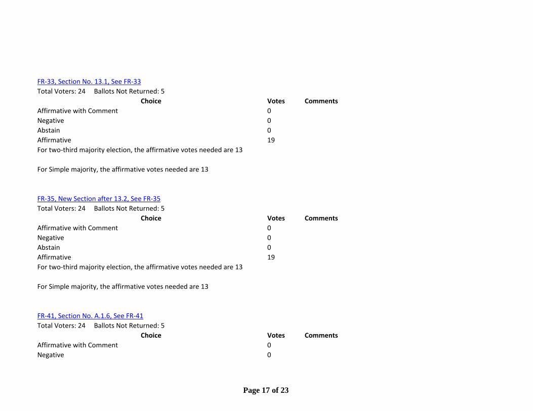
FR-33, Section No. 13.1, See FR-33Total Voters: 24 Ballots Not Returned: 5
Choice Votes CommentsAffirmative with Comment 0Negative 0Abstain 0Affirmative 19For two-third majority election, the affirmative votes needed are 13
For Simple majority, the affirmative votes needed are 13
FR-35, New Section after 13.2, See FR-35Total Voters: 24 Ballots Not Returned: 5
Choice Votes CommentsAffirmative with Comment 0Negative 0Abstain 0Affirmative 19For two-third majority election, the affirmative votes needed are 13
For Simple majority, the affirmative votes needed are 13
FR-41, Section No. A.1.6, See FR-41Total Voters: 24 Ballots Not Returned: 5
Choice Votes CommentsAffirmative with Comment 0Negative 0
Page 17 of 23

Abstain 0Affirmative 19For two-third majority election, the affirmative votes needed are 13
For Simple majority, the affirmative votes needed are 13
FR-52, Section No. A.5.8, See FR-52Total Voters: 24 Ballots Not Returned: 5
Choice Votes CommentsAffirmative with Comment 0Negative 0Abstain 0Affirmative 19For two-third majority election, the affirmative votes needed are 13
For Simple majority, the affirmative votes needed are 13
FR-23, New Section after A.8.5.15.6, See FR-23Total Voters: 24 Ballots Not Returned: 5
Choice Votes CommentsAffirmative with Comment 0Negative 0Abstain 0Affirmative 19For two-third majority election, the affirmative votes needed are 13
For Simple majority, the affirmative votes needed are 13
Page 18 of 23

FR-53, Section No. A.9.12.2, See FR-53Total Voters: 24 Ballots Not Returned: 5
Choice Votes CommentsAffirmative with Comment 0Negative 0Abstain 0Affirmative 19For two-third majority election, the affirmative votes needed are 13
For Simple majority, the affirmative votes needed are 13
FR-24, New Section after A.9.14.7, See FR-24Total Voters: 24 Ballots Not Returned: 5
Choice Votes CommentsAffirmative with Comment 0Negative 0Abstain 0Affirmative 19For two-third majority election, the affirmative votes needed are 13
For Simple majority, the affirmative votes needed are 13
FR-42, Section No. A.10.15.7, See FR-42Total Voters: 24 Ballots Not Returned: 5
Choice Votes CommentsAffirmative with Comment 0Negative 0
Page 19 of 23

Abstain 0Affirmative 19For two-third majority election, the affirmative votes needed are 13
For Simple majority, the affirmative votes needed are 13
FR-36, Section No. A.12.2, See FR-36Total Voters: 24 Ballots Not Returned: 5
Choice Votes CommentsAffirmative with Comment 0Negative 0Abstain 0Affirmative 19For two-third majority election, the affirmative votes needed are 13
For Simple majority, the affirmative votes needed are 13
FR-39, Section No. F.1.1, See FR-39Total Voters: 24 Ballots Not Returned: 5
Choice Votes CommentsAffirmative with Comment 1David McFarlin Although voting affirmative I think more study
needs to be done relative to the new edition standards and how they may have an affect on 302
Negative 0Abstain 0Affirmative 18For two-third majority election, the affirmative votes needed are 13
Page 20 of 23

For Simple majority, the affirmative votes needed are 13
FR-38, Section No. F.1.2.1, See FR-38Total Voters: 24 Ballots Not Returned: 5
Choice Votes CommentsAffirmative with Comment 1David McFarlin Although voting affirmative I think more study
needs to be done relative to the new edition standards and how they may have an affect on 302
Negative 0Abstain 0Affirmative 18For two-third majority election, the affirmative votes needed are 13
For Simple majority, the affirmative votes needed are 13
FR-40, Section No. F.1.2.2, See FR-40Total Voters: 24 Ballots Not Returned: 5
Choice Votes CommentsAffirmative with Comment 1David McFarlin Although voting affirmative I think more study
needs to be done relative to the new edition standards and how they may have an affect on 302
Negative 0Abstain 0Affirmative 18For two-third majority election, the affirmative votes needed are 13
Page 21 of 23
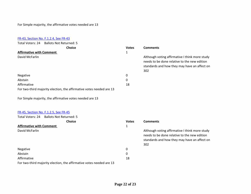
For Simple majority, the affirmative votes needed are 13
FR-43, Section No. F.1.2.4, See FR-43Total Voters: 24 Ballots Not Returned: 5
Choice Votes CommentsAffirmative with Comment 1David McFarlin Although voting affirmative I think more study
needs to be done relative to the new edition standards and how they may have an affect on 302
Negative 0Abstain 0Affirmative 18For two-third majority election, the affirmative votes needed are 13
For Simple majority, the affirmative votes needed are 13
FR-45, Section No. F.1.2.5, See FR-45Total Voters: 24 Ballots Not Returned: 5
Choice Votes CommentsAffirmative with Comment 1David McFarlin Although voting affirmative I think more study
needs to be done relative to the new edition standards and how they may have an affect on 302
Negative 0Abstain 0Affirmative 18For two-third majority election, the affirmative votes needed are 13
Page 22 of 23

For Simple majority, the affirmative votes needed are 13
FR-44, Section No. F.3, See FR-44Total Voters: 24 Ballots Not Returned: 5
Choice Votes CommentsAffirmative with Comment 0Negative 0Abstain 0Affirmative 19For two-third majority election, the affirmative votes needed are 13
For Simple majority, the affirmative votes needed are 13
FR-30, New Section after 12.1.3.6.1, See FR-30Total Voters: 24 Ballots Not Returned: 5
Choice Votes CommentsAffirmative with Comment 0Negative 1David McFarlin No scientific study was done to support this
change.Abstain 0Affirmative 18For two-third majority election, the affirmative votes needed are 13
For Simple majority, the affirmative votes needed are 13
Page 23 of 23
Committee Input No. 32-NFPA 302-2012 [ Section No. 12.1.2.4 ]
12.1.2.4 Portable fire extinguishers, other than those addressed in 12.1.2.6, shall be U.S. Coast Guard–approved.
Submitter Information Verification
Submitter Full Name: [ Not Specified ]
Organization: [ Not Specified ]
Submittal Date: Tue Aug 28 14:50:24 EDT 2012
Committee Statement and Meeting Notes
CommitteeStatement:
The Committee wants to make the requirement compliant with NFPA 2001 and is interested in getting feedback from affected stakeholders and the US Coast Guard on this change to the requirement.
ResponseMessage:
CI-32-NFPA 302-2012
Page 1 of 11National Fire Protection Association Report
11/1/2012http://submittals.nfpa.org/TerraViewWeb/ContentFetcher?commentParams=%28Comment...

Committee Input No. 31-NFPA 302-2012 [ Section No. 12.1.3.4 ]
12.1.3.4*Fixed systems shall comply with the following criteria:
(1) They shall meet the requirements of the manufacturer's instructions.
(2) They shall meet the requirements of NFPA 12, Standard on Carbon Dioxide Extinguishing Systems; NFPA 12A, Standard on Halon 1301 Fire Extinguishing Systems; NFPA 2001, Standard on Clean Agent Fire Extinguishing Systems; or NFPA 2010, Standard for Fixed Aerosol Fire-Extinguishing Systems, as appropriate, and shall be listed to theapplicable ANSI/UL marine standard.
(3) For installation on pleasure craft, they shall be U.S. Coast Guard–approved.
Submitter Information Verification
Submitter Full Name: [ Not Specified ]
Organization: [ Not Specified ]
Submittal Date: Tue Aug 28 14:45:20 EDT 2012
Committee Statement and Meeting Notes
CommitteeStatement:
The Committee wants to make the requirement compliant with NFPA 2001 and is interested in getting feedback from affected stakeholders and the US Coast Guard on this change to the requirement.
ResponseMessage:
CI-31-NFPA 302-2012
Page 2 of 11National Fire Protection Association Report
11/1/2012http://submittals.nfpa.org/TerraViewWeb/ContentFetcher?commentParams=%28Comment...
Committee Input No. 57-NFPA 302-2012 [ Sections E.1, E.2, E.3, E.4,
E.5, E.6 ]
E.1 Introduction.This annex is provided as an aid to the user of NFPA 302 by identifying those portions of NFPA standards that pertain to inspection and frequency of maintenance of fixed extinguishing systems and portable fire extinguishers. It is not intended that this annex provide complete information regarding all aspects of servicing fire protection equipment. It is important to note that this information was not copied using NFPA's extract policy and is not intended to be a part of the requirements of NFPA 302 unless specified in Chapter 1through Chapter 12. While the 2002 edition of NFPA 10, the 2000 edition ofNFPA 12, the 2001 edition of NFPA 12A, and the 2000 edition of NFPA 2001were the most current at the time of the publication of the 2004 edition ofNFPA 302, more recent editions might have been issued.E.2 Definitions.See NFPA 10, Standard for Portable Fire Extinguishers, NFPA 12, Standard on Carbon Dioxide Extinguishing Systems, NFPA 12A, Standard on Halon 1301 Fire Extinguishing Systems, and NFPA 2001, Standard on Clean Agent Fire Extinguishing Systems, for definition of terms used in this annex.E.3 Inspection, Maintenance, and Recharging Portable Fire Extinguishers.E.3.1 General.E.3.1.1 This section is concerned with the rules governing inspection, maintenance, and recharging of fire extinguishers. These factors are of prime importance in ensuring operation at the time of a fire. [10:6.1.1]E.3.1.2 The procedure for inspection and maintenance of fire extinguishers varies considerably. Minimal knowledge is necessary to perform a monthly “quick check” or inspection in order to follow the inspection procedure as outlined in E.3.2. A trained person who has undergone the instructions necessary to reliably perform maintenance and has the manufacturer's service manual shall service the fire extinguishers not more than 1 year apart. [10:6.1.2]E.3.1.3 The owner or designated agent or occupant of a property in which fire extinguishers are located shall be responsible for such inspection, maintenance, and recharging. (See E.3.1.2 and E.3.1.4.) [10:6.1.3]E.3.1.4 Maintenance, servicing, and recharging shall be performed by trained persons having available the appropriate servicing manual(s), the proper types of tools, recharge materials, lubricants, and manufacturer's recommended replacement parts or parts specifically listed for use in the fire extinguisher. [10:6.1.4]E.3.1.5 Tags or labels shall not be placed on the front of the fire extinguisher.[10:6.1.5]E.3.1.6 Labels indicating fire extinguisher use or classification or both shall be permitted to be placed on the front of the fire extinguisher. [10:6.1.6]E.3.2 Inspection.
Page 3 of 11National Fire Protection Association Report
11/1/2012http://submittals.nfpa.org/TerraViewWeb/ContentFetcher?commentParams=%28Comment...
E.3.2.1 Frequency.Fire extinguishers shall be inspected when initially placed in service and thereafter at approximately 30-day intervals. Fire extinguishers shall be inspected, manually or by electronic monitoring, at more frequent intervals when circumstances require. [10:6.2.1]E.3.2.2 Procedures.Periodic inspection of fire extinguishers shall include a check of at least the following items:
(1) Location in designated place
(2) No obstruction to access or visibility
(3) Operating instructions on nameplate legible and facing outward
(4) Safety seals and tamper indicators not broken or missing
(5) Fullness determined by weighing or “hefting”
(6) Examination for obvious physical damage, corrosion, leakage, or clogged nozzle
(7) Pressure gauge reading or indicator in the operable range or position
(8) Condition of tires, wheels, carriage, hose, and nozzle checked (for wheeled units)
(9) HMIS label in place [10:6.2.2]
E.3.2.3 Corrective Action.When an inspection of any fire extinguisher reveals a deficiency in any of theconditions listed in E.3.2.2, immediate corrective action shall be taken.[10:6.2.3]E.3.2.3.1 Rechargeable Fire Extinguishers.When an inspection of any rechargeable fire extinguisher reveals a deficiency in any of the conditions listed in E.3.2.2(3), E.3.2.2(4), E.3.2.2(5), E.3.2.2(6), E.3.2.2(7), and E.3.2.2(8), it shall be subjected to applicable maintenance procedures. [10:6.2.3.1]E.3.2.3.2 Nonrechargeable Dry Chemical Fire Extinguisher.When an inspection of any nonrechargeable dry chemical fire extinguisher reveals a deficiency in any of the conditions listed in E.3.2.2(3), E.3.2.2(5),E.3.2.2(6), and E.3.2.2(7), it shall be removed from further use, discharged, and destroyed at the direction of the owner or returned to the manufacturer.[10:6.2.3.2]E.3.2.3.3 Nonrechargeable Halon Agent Fire Extinguisher.When an inspection of any nonrechargeable fire extinguisher containing a halon agent reveals a deficiency in any of the conditions listed in E.3.2.2(3),E.3.2.2(5), E.3.2.2(6), and E.3.2.2(7), it shall be removed from service, not discharged, and returned to the manufacturer. If the fire extinguisher is not returned to the manufacturer, it shall be returned to a fire equipment dealer or distributor to permit recovery of the halon. [10:6.2.3.3]E.3.2.4 Inspection Recordkeeping.E.3.2.4.1 Personnel making inspections shall keep records of all fire extinguishers inspected, including those found to require corrective action. [10:6.2.4.1]E.3.2.4.2 At least monthly, the date the inspection was performed and the initials of the person performing the inspection shall be recorded. [10:6.2.4.2]E.3.2.4.3
Page 4 of 11National Fire Protection Association Report
11/1/2012http://submittals.nfpa.org/TerraViewWeb/ContentFetcher?commentParams=%28Comment...
Records shall be kept on a tag or label attached to the fire extinguisher, on an inspection checklist maintained on file or by an electronic method that provides a permanent record. [10:6.2.4.3]E.4 Inspection and Maintenance of Fixed CO2 Systems.E.4.1 General.E.4.1.1 Persons who inspect, test, maintain, or operate carbon dioxide fire-extinguishing systems shall be thoroughly trained in the functions they perform. [12:1.11.4]E.4.1.2 Prior to testing or maintenance of a fixed carbon dioxide system, all personnel shall be evacuated from the protected space (See Section 1.6 of NFPA 12). [12:6.3.1]E.4.2 Inspection.E.4.2.1 At least every 30 days, an inspection shall be conducted to assess the system's operational condition. [12:1.11.1]E.4.2.2 An inspection is a “quick check” to give reasonable assurance that the extinguishing system is fully charged and operable and is done by seeing that the system is in place, that it has not been activated or tampered with, and that there is no obvious physical damage or condition to prevent operation. As a minimum, the inspection should determine the following:
(1) High-pressure cylinders are in place and properly secured.
(2) For low-pressure storage unit, that pressure gauge shows normal pressure, that tank shutoff valve is open, and that pilot pressure supply valve is open. Liquid level gauge should be observed. If at any time a container shows a loss of more than 10 percent, it should be refilled, unless the minimum gas requirements are still provided.
(3) Carbon dioxide storage is connected to discharge piping and actuators.
(4) All manual actuators are in place and tamper seals are intact.
(5) Nozzles are connected, properly aligned, and free from obstructions and foreign matter.
(6) Detectors are in place and free from foreign matter and obstructions.
(7) System control panel is connected and showing “normal-ready” condition. [12: A.1.11.1]
E.4.2.3 All system hose including those used as flexible connectors shall be tested every 5 years in accordance with 1.11.2 of NFPA 12. [12:1.11.2.1]E.4.3 Maintenance.E.4.3.1 A manufacturer's test and maintenance procedure shall be provided to the owner for testing and maintenance of the system. This procedure shall provide for the initial testing of the equipment as well as for periodic test inspection and maintenance of the system. [12:1.11.3.1]E.4.3.2 The following shall be verified by competent personnel at least annually usingavailable documentation required in 1.7.2.6 of NFPA 12.
(1) Check and test the carbon dioxide system for proper operation.
Page 5 of 11National Fire Protection Association Report
11/1/2012http://submittals.nfpa.org/TerraViewWeb/ContentFetcher?commentParams=%28Comment...
(2) Check that there have been no changes to the size, type, and configuration of the hazard and system. [12:1.11.3.2]
E.4.3.2.1 The goal of this maintenance and testing shall be not only to ensure that the system is in full operating condition, but shall indicate the probable continuance of that condition until the next inspection. [12:1.11.3.2.1]E.4.3.2.2 Suitable discharge tests shall be made when any maintenance indicates their advisability. Prior to testing, proper safety procedures shall be reviewed. (See Section 1.6 and A.1.6 of NFPA 12.) [12:1.11.3.2.2]E.4.3.3 A maintenance report with recommendations shall be filed with the owner.[12:1.11.3.3]E.4.3.4 Between the regular service contract maintenance or tests, the system shall be inspected visually or otherwise by approved or competent personnel who follow an approved schedule. [12:1.11.3.4]E.4.3.5 At least semiannually, all high-pressure cylinders shall be weighed and the date of the last hydrostatic test noted (see 1.9.5.1 of NFPA 12). If, at any time, a container shows a loss in net content of more than 10 percent, it shall be refilled or replaced. [12:1.11.3.5]E.4.3.6 At least weekly, the liquid level gauges of low-pressure containers shall be observed. If at any time a container shows a loss of more than 10 percent, it shall be refilled, unless the minimum gas requirements are still provided.[12:1.11.3.6]E.4.3.7 Testing of heat, smoke, and flame detectors shall be in accordance with Chapter 7 of NFPA 72. [12:1.11.3.7]E.4.3.8 These systems shall be kept in full operating condition at all times. Use, impairment, and restoration of this protection shall be reported promptly to the authority having jurisdiction. Any troubles or impairments shall be corrected at once by competent personnel. [12:1.11.3.8]E.5 Inspection and Tests of Fixed Halogenated Agent Systems.E.5.1 General.E.5.1.1 All persons who could be expected to inspect, test, maintain, operate, or decommission and remove fire extinguishing systems shall be thoroughly trained and kept thoroughly trained in the functions they are expected to perform. [12A:4.6]E.5.1.2 Personnel working in a halon-protected enclosure shall receive training regarding halon safety issues. [12A:4.6.1]E.5.2 Inspection.E.5.2.1 At least semiannually, all systems shall be thoroughly inspected, tested, and documented for proper operation by trained competent personnel. Tests shall be in accordance with the appropriate NFPA or Canadian standards.[12A:4.1.1]E.5.2.2
Page 6 of 11National Fire Protection Association Report
11/1/2012http://submittals.nfpa.org/TerraViewWeb/ContentFetcher?commentParams=%28Comment...

Some protected area conditions could require inspections more frequent than semiannually. A service contract with an approved fire protection contractor is recommended. The inspection and test is to be conducted in accordance with the manufacturer's recommendations and procedures and appropriate NFPA standards and guides. Inspection criteria include but are not limited to the following:
(1) Detection. All detectors are to be checked for proper alarm, supervision, and trouble functions.
(2) Actuation.
(a) Remove automatic actuation controls from agent containers. Test detection system to operate the necessary circuit(s) to simulate agent release.
(b) Operate all manual devices to simulate agent release.
(c) After testing, reset and reinstall all actuation controls.
(3) Containers.
(a) Examine all containers for evidence of corrosion or mechanical damage.
(b) Check container bracketing and supports to determine that their condition is satisfactory.
(4) Piping and Nozzles.
(a) Examine piping for any evidence of corrosion.
(b) Examine pipe hangers and straps to see that the piping is securely supported.
(c) Check nozzles for proper position and alignment and determine that the orifices are clear and unobstructed.
(d) Check nozzle seals, if applicable, for signs of deterioration and replace if necessary.
(5) Auxiliary Equipment.
(a) Operate all auxiliary and supplementary components such as switches, door and window releases, interconnected valves, damper releases, air handling equipment shutdown, and supplementary alarms to ensure that they are in proper operating condition.
(b) Return all devices to normal “operating” condition after testing. [12A: A.4.1]
E.5.2.3 The documented report with recommendations shall be filed with the owner.[12A:4.1.2]E.5.2.4 The agent quantity and pressure of refillable containers shall be checked. If a container shows a loss in net weight of more than 5 percent or a loss in pressure (adjusted for temperature) of more than 10 percent, it shall be refilled or replaced. When the amount of agent in the container is determined by special measuring devices in lieu of weighing, these devices shall be listed. [12A:4.1.3]E.5.2.5 All halon removed from refillable containers during service or maintenance procedures shall be collected for recycling. [12A:4.1.4]
Page 7 of 11National Fire Protection Association Report
11/1/2012http://submittals.nfpa.org/TerraViewWeb/ContentFetcher?commentParams=%28Comment...

E.5.2.6 Factory-charged nonrefillable containers that do not have a means of pressure indication shall be weighed at least semiannually. If a container shows a loss in net weight of more than 5 percent, it shall be replaced. All factory-charged nonrefillable containers removed from useful service shall be returned for recycling of the agent. [12A:4.1.5]E.5.2.7 The weight and pressure of the container shall be recorded on a tag attached to the container. [12A:4.1.6]E.5.3 Containers.E.5.3.1 DOT, CTC, or similar design Halon 1301 cylinders shall not be recharged without a retest if more than 5 years have elapsed since the date of the last test and inspection. The retest shall be permitted to consist of a complete visual inspection as described in the Code of Federal Regulations, Title 49,“Transportation,” Parts 170–190 and Subpart C, Section 173.34(e)(10), andSection 178.36 through 178.68. In Canada, the corresponding information is set forth in the Canadian Transport Commission's Regulations for the Transportation of Dangerous Commodities by Rail. [12A: 4.2.1]E.5.3.2 Cylinders continuously in service without discharging shall be given a complete external visual inspection every 5 years, in accordance with Compressed Gas Association pamphlet C-6, Section 3, except that the cylinders need not be emptied or stamped while under pressure. [12A:4.2.2]E.5.3.3 Where external visual inspection indicates that the container has been damaged, additional strength tests shall be required. CAUTION: If additional tests used include hydrostatic testing, containers should be thoroughly dried before refilling. [12A:4.2.3]E.5.4 Hoses.E.5.4.1 All system hoses shall be examined annually for damage. If visual examination shows any deficiency, the hose shall be immediately replaced or tested as specified in 4-3.1 of NFPA 12A. [12A:4.3]E.5.4.2 All hoses shall be tested every 5 years in accordance with 4-3.1 of NFPA 12A. [12A:4.3.2]E.5.5 Enclosure Inspection.At least every 6 months the halon-protected enclosure shall be thoroughly inspected to determine if penetrations or other changes have occurred that could adversely affect halon leakage.
Where the inspection indicates that conditions that could result in inability to maintain the halon concentration, they shall be corrected. If uncertainty still exists, the enclosures shall be retested for integrity. [12A:4.4]
E.5.6 Maintenance.E.5.6.1 These systems shall be maintained in full operating condition at all times. Use, impairment, and restoration of this protection shall be reported promptly to the authority having jurisdiction. [12A:4.5.1]E.5.6.2 Any troubles or impairments shall be corrected at once by competent personnel. [12A:4.5.2]E.5.6.3
Page 8 of 11National Fire Protection Association Report
11/1/2012http://submittals.nfpa.org/TerraViewWeb/ContentFetcher?commentParams=%28Comment...

Any penetrations made through the halon-protected enclosure shall be sealed immediately. The method of sealing shall restore the original fire resistance rating and tightness of the enclosure. [12A:4.5.3]E.6 Inspection and Tests of Clean Agent Systems.E.6.1 Training.E.6.1.1 All persons who could be expected to inspect, test, maintain, or operate fire extinguishing systems shall be thoroughly trained and kept thoroughly trained in the functions they are expected to perform. [2001:4.6.1]E.6.1.2 Personnel working in an enclosure protected by a clean agent shall receive training regarding agent safety issues. [2001:4.6.2]E.6.2 Safety.Safe procedures shall be observed during installation, servicing, maintenance, testing, handling, and recharging of clean agent systems and agent containers. [2001:4.8]E.6.3 Inspection and Testing.E.6.3.1 The installing contractor shall provide instructions for the operational features and inspection procedures specific to the clean agent system installed on the vessel. [2001:5.11.4]E.6.3.2 At least annually, all systems shall be thoroughly inspected and tested for proper operation by competent personnel. Discharge tests are not required.[2001:5.11]E.6.3.3 An inspection report with recommendations shall be filed with the vessel's master and the owner's agent. The report shall be available for inspection by the authority having jurisdiction. [2001:5.11.1]E.6.3.4 At least annually, the agent quantity of refillable containers shall be checked by competent personnel. The container pressure shall be verified and logged at least monthly by the vessel's crew. [2001:5.11.2]E.6.3.5 For halocarbon clean agents, if a container shows a loss in agent of more than 5 percent or a loss in pressure, adjusted for temperature, of more than 10 percent, it shall be refilled or replaced. [2001:5.11.3]E.6.3.6 For inert gas clean agents that are not liquefied, pressure is an indication of agent quantity. If an inert gas clean agent container shows a loss in pressure, adjusted for temperature, of more than 5 percent, it shall be refilled or replaced. Where container pressure gauges are used for this purpose, they shall be compared to a separate calibrated device at least annually.[2001:5.11.3.1]E.6.3.7 Where the amount of agent in the container is determined by special measuring devices, these devices shall be listed. [2001:4.1.3.3]E.6.3.8 All halocarbon clean agent removed from refillable containers during service or maintenance procedures shall be collected and recycled or disposed of in an environmentally sound manner and in accordance with existing laws and regulations. [2001:4.1.4]E.6.3.9
Page 9 of 11National Fire Protection Association Report
11/1/2012http://submittals.nfpa.org/TerraViewWeb/ContentFetcher?commentParams=%28Comment...
Factory-charged, nonrefillable containers that do not have a means of pressure indication shall have the agent quantity checked at least semiannually. If a container shows a loss in agent quantity of more than 5 percent, it shall be replaced. All factory-charged, nonrefillable containers removed from useful service shall be returned for recycling of the agent or disposed of in an environmentally sound manner and in accordance with existing laws and regulations. [2001:4.1.5]E.6.3.10 For halocarbon clean agents, the date of inspection, gross weight of cylinder plus agent or net weight of agent, type of agent, person performing the inspection, and, where applicable, the pressure at a recorded temperature shall be recorded on a tag attached to the container. For inert gas clean agents, the date of inspection, type of agent, person performing the inspection, and the pressure at a recorded temperature shall be recorded on a tag attached to the container. [2001:4.1.6]E.6.3.11 Containers.E.6.3.11.1 U.S. Department of Transportation (DOT), Canadian Transport Commission (CTC), or similar design clean agent containers shall not be recharged without retesting if more than 5 years have elapsed since the date of the last test and inspection. For halocarbon agent storage containers, the retest shall be permitted to consist of a complete visual inspection as described in 49 CFR 173.34(e)(10).
Transporting charged containers that have not been tested within 5 years could be illegal. Federal and local regulations should be consulted.[2001:4.2.1]
E.6.3.11.2 Cylinders continuously in service without discharging shall be given a complete external visual inspection every 5 years or more frequently if required. The visual inspection shall be in accordance with Section 3 of CGAC-6, Standard for Visual Inspection of Steel Compressed Gas Cylinders, except that the cylinders need not be emptied or stamped while under pressure. Inspections shall be made only by competent personnel and the results recorded on both of the following:
(1) A record tag permanently attached to each cylinder
(2) A suitable inspection report
A completed copy of the inspection report shall be furnished to the owner of the system or an authorized representative. These records shall be retained by the owner for the life of the system. [2001:4.2.2]
E.6.3.11.3 Where external visual inspection indicates that the container has been damaged, additional strength tests shall be required. [2001:4.2.3]E.6.3.12 Hoses.E.6.3.12.1 All system hose shall be examined annually for damage. If visual examination shows any deficiency, the hose shall be immediately replaced or tested as specified in 4-3.2 of NFPA 2001. [2001:4.3.1]E.6.3.12.2 All hose shall be tested every 5 years in accordance with 4.3.2.2 of NFPA 2001. [2001:4.3.2.1]E.6.4 Enclosure Inspection.
Page 10 of 11National Fire Protection Association Report
11/1/2012http://submittals.nfpa.org/TerraViewWeb/ContentFetcher?commentParams=%28Comment...

At least every 12 months, the enclosure protected by the clean agent shall be thoroughly inspected to determine if penetrations or other changes have occurred that could adversely affect agent leakage or change volume of hazard or both. Where the inspection indicates conditions that could result in inability to maintain the clean agent concentration, they shall be corrected. If uncertainty still exists, the enclosures shall be retested for integrity in accordance with 4.7.2.3 of NFPA 2001.
An enclosure inspection is not required every 12 months if a documentedadministrative control program exists that addresses barrier integrity.[2001:4.4]
E.6.5 Maintenance.E.6.5.1 These systems shall be maintained in full operating condition at all times. Actuation, impairment, and restoration of this protection shall be reported promptly to the authority having jurisdiction. [2001:4.5.1]E.6.5.2 Any troubles or impairments shall be corrected in a timely manner consistent with the hazard protected. [2001:4.5.2]E.6.5.3 Any penetrations made through the enclosure protected by the clean agent shall be sealed immediately. The method of sealing shall restore the original fire resistance rating of the enclosure. [2001:4.5.3]
Submitter Information Verification
Submitter Full Name: Larry Russell
Organization: National Fire Protection Assoc
Submittal Date: Fri Aug 31 14:58:21 EDT 2012
Committee Statement and Meeting Notes
Committee Statement:
The Committee has revised Annex E with extracts from the current editions of: NFPA 10, Standard for Portable Fire Extinguishers, NFPA 12, Standard on Carbon Dioxide Extinguishing Systems, NFPA 12A, Standard on Halon 1301 Fire Extinguishing Systems, and NFPA 2001, Standard on Clean Agent Fire Extinguishing Systems. This section was last revised in the 2004 edition of the Standard.
ResponseMessage:
CI-57-NFPA 302-2012
Page 11 of 11National Fire Protection Association Report
11/1/2012http://submittals.nfpa.org/TerraViewWeb/ContentFetcher?commentParams=%28Comment...