nextmove bx installation manual · nextmove bx installation manual for mint™ v4 2 mn1258v4...
TRANSCRIPT
MN1258V4 08/2000
NextMove BXInstallation Manual for Mint v4
Issue 4.0

NextMove BX Installation Manual for Mint™ v4
ii MN1258V4 08/2000
Copyright
MN1258V4 08/2000 iii
Copyright Baldor UK Ltd © 2000. All rights reserved.
This manual is copyrighted and all rights are reserved. This document or attached software may not, in whole or in part, becopied or reproduced in any form without the prior written consent of Baldor UK.Baldor Optimised Control makes no representations or warranties with respect to the contents hereof and specificallydisclaims any implied warranties of fitness for any particular purpose. The information in this document is subject to changewithout notice. Baldor UK assumes no responsibility for any errors that may appear in this document.
MINT™ is a registered trademark of Baldor UK Ltd.Windows 95, Windows 98 and Windows NT are registered trademarks of the Microsoft Corporation.
Limited WarrantyFor a period of one (1) year from the date of original purchase, BALDOR will repair or replace without charge controlswhich our examination proves to be defective in material or workmanship. This warranty is valid if the unit has not beentampered with by unauthorized persons, misused, abused, or improperly installed and has been used in accordance with theinstructions and/or ratings supplied. This warranty is in lieu of any other warranty or guarantee expressed or implied.BALDOR shall not be held responsible for any expense (including installation and removal), inconvenience, orconsequential damage, including injury to any person or property caused by items of our manufacture or sale. (Some statesdo not allow exclusion or limitation of incidental or consequential damages, so the above exclusion may not apply.) In anyevent, BALDOR’s total liability, under all circumstances, shall not exceed the full purchase price of the control. Claims forpurchase price refunds, repairs, or replacements must be referred to BALDOR with all pertinent data as to the defect, the datepurchased, the task performed by the control, and the problem encountered. No liability is assumed for expendable itemssuch as fuses.Goods may be returned only with written notification including a BALDOR Return Authorization Number and any returnshipments must be prepaid.
Baldor UK LtdMint Motion Centre6 Bristol Distribution ParkHawkley DriveBristolBS32 0BFU.K.Telephone: +44 (0) 1454 850 000Fax: +44 (0) 1454 859 001Web site: www.baldor.co.ukSales email: [email protected] email: [email protected]
Baldor Electric CompanyTelephone: +1 501 646 4711Fax: +1 501 648 5792email: [email protected] site: www.baldor.com
Baldor ASR GmbHTelephone: +49 (0) 89 90508-0Fax: +49 (0) 89 90508-492
Baldor ASR AGTelephone: +41 (0) 52 647 4700Fax: +41 (0) 52 659 2394
Australian Baldor Pty LtdTelephone: +61 2 9674 5455Fax: +61 2 9674 2495
Baldor Electric (F.E.) Pte LtdTelephone: +65 744 2572Fax: +65 747 1708

NextMove BX Installation Manual for Mint™ v4
iv MN1258V4 08/2000
Copyright
MN1258V4 08/2000 v
Safety Notice: Only qualified personnel should attempt the start-up procedureor troubleshoot this equipment.
This equipment may be connected to other machines that have rotating parts or parts that arecontrolled by this equipment. Improper use can cause serious or fatal injury. Only qualifiedpersonnel should attempt to start-up, program or troubleshoot this equipment.
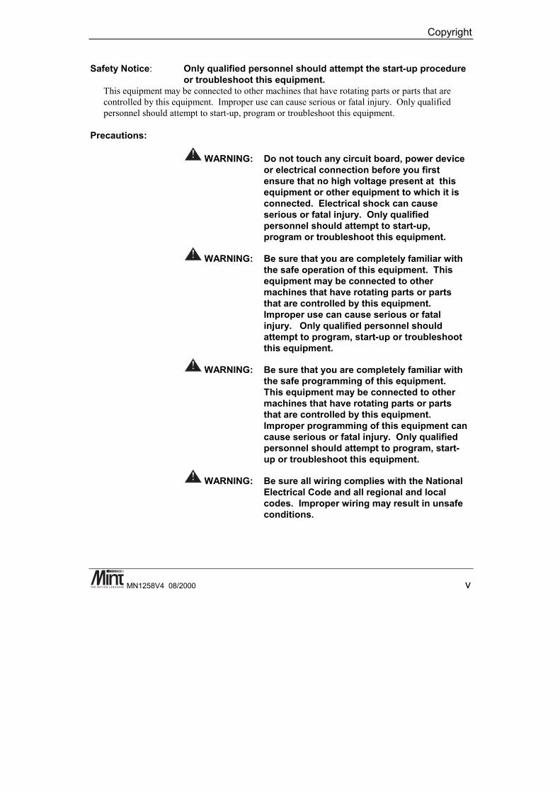
Precautions:
WARNING: Do not touch any circuit board, power deviceor electrical connection before you firstensure that no high voltage present at thisequipment or other equipment to which it isconnected. Electrical shock can causeserious or fatal injury. Only qualifiedpersonnel should attempt to start-up,program or troubleshoot this equipment.
WARNING: Be sure that you are completely familiar withthe safe operation of this equipment. Thisequipment may be connected to othermachines that have rotating parts or partsthat are controlled by this equipment.Improper use can cause serious or fatalinjury. Only qualified personnel shouldattempt to program, start-up or troubleshootthis equipment.
WARNING: Be sure that you are completely familiar withthe safe programming of this equipment.This equipment may be connected to othermachines that have rotating parts or partsthat are controlled by this equipment.Improper programming of this equipment cancause serious or fatal injury. Only qualifiedpersonnel should attempt to program, start-up or troubleshoot this equipment.
WARNING: Be sure all wiring complies with the NationalElectrical Code and all regional and localcodes. Improper wiring may result in unsafeconditions.
NextMove BX Installation Manual for Mint™ v4
vi MN1258V4 08/2000
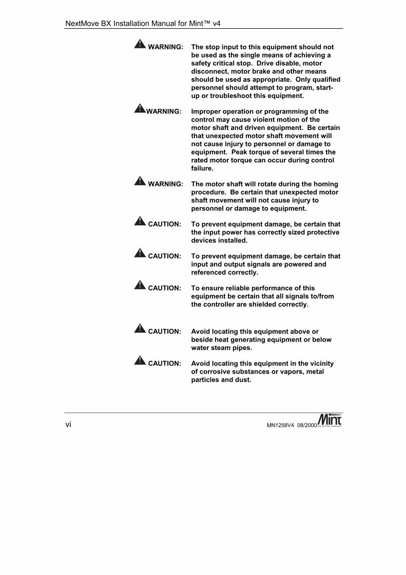
WARNING: The stop input to this equipment should notbe used as the single means of achieving asafety critical stop. Drive disable, motordisconnect, motor brake and other meansshould be used as appropriate. Only qualifiedpersonnel should attempt to program, start-up or troubleshoot this equipment.
WARNING: Improper operation or programming of thecontrol may cause violent motion of themotor shaft and driven equipment. Be certainthat unexpected motor shaft movement willnot cause injury to personnel or damage toequipment. Peak torque of several times therated motor torque can occur during controlfailure.
WARNING: The motor shaft will rotate during the homingprocedure. Be certain that unexpected motorshaft movement will not cause injury topersonnel or damage to equipment.
CAUTION: To prevent equipment damage, be certain thatthe input power has correctly sized protectivedevices installed.
CAUTION: To prevent equipment damage, be certain thatinput and output signals are powered andreferenced correctly.
CAUTION: To ensure reliable performance of thisequipment be certain that all signals to/fromthe controller are shielded correctly.
CAUTION: Avoid locating this equipment above orbeside heat generating equipment or belowwater steam pipes.
CAUTION: Avoid locating this equipment in the vicinityof corrosive substances or vapors, metalparticles and dust.
Manual Revision History
MN1258V4 08/2000 vii
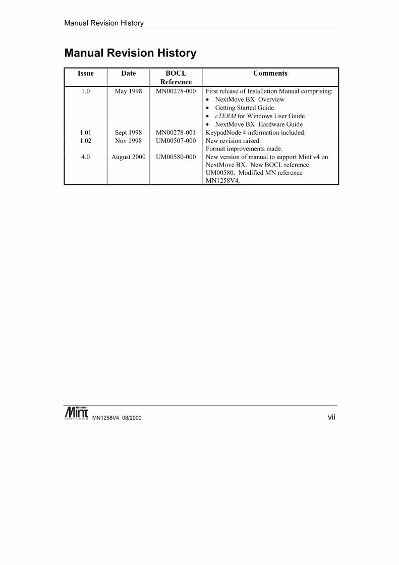
Manual Revision HistoryIssue Date BOCL
ReferenceComments
1.0 May 1998 MN00278-000 First release of Installation Manual comprising:• NextMove BX Overview• Getting Started Guide• cTERM for Windows User Guide• NextMove BX Hardware Guide
1.01 Sept 1998 MN00278-001 KeypadNode 4 information included.1.02 Nov 1998 UM00507-000 New revision raised.
Format improvements made.4.0 August 2000 UM00580-000 New version of manual to support Mint v4 on
NextMove BX. New BOCL referenceUM00580. Modified MN referenceMN1258V4.

NextMove BX Installation Manual for Mint™ v4
viii MN1258V4 08/2000

Manual Revision History
MN1258V4 08/2000 ix
Read Me First ............................................................................. 11.1 Key to Symbols Used in this Manual.........................................................2
Product Overview ...................................................................... 3
Hardware Guide ......................................................................... 73.1 Operating Environment.............................................................................93.2 NextMove BX PCB Settings.....................................................................93.3 Power Connection ..................................................................................11
3.3.1 Front Panel Power Connection: J8.....................................................123.4 Digital I/O................................................................................................13
3.4.1 Digital Inputs: J1 and J2.....................................................................133.4.2 Fast Interrupts: J6 ..............................................................................153.4.3 Digital Outputs: J4..............................................................................16
3.5 Analog I/O ..............................................................................................193.5.1 Analog Inputs: J3 ...............................................................................193.5.2 Analog Outputs (Drive Command: J7)................................................20
3.6 Encoder Interface ...................................................................................213.7 Relay: J5.................................................................................................243.8 Serial Ports .............................................................................................24
3.8.1 RS232................................................................................................253.8.2 RS485................................................................................................263.8.3 RS485 Multi-Drop...............................................................................273.8.4 CAN Bus ............................................................................................28
3.9 Reset State.............................................................................................303.10 Battery Backup of Memory......................................................................31
3.10.1 Changing the Battery .........................................................................313.10.2 Charging the Battery ..........................................................................32
NextMove BX Installation Manual for Mint™ v4
x MN1258V4 08/2000
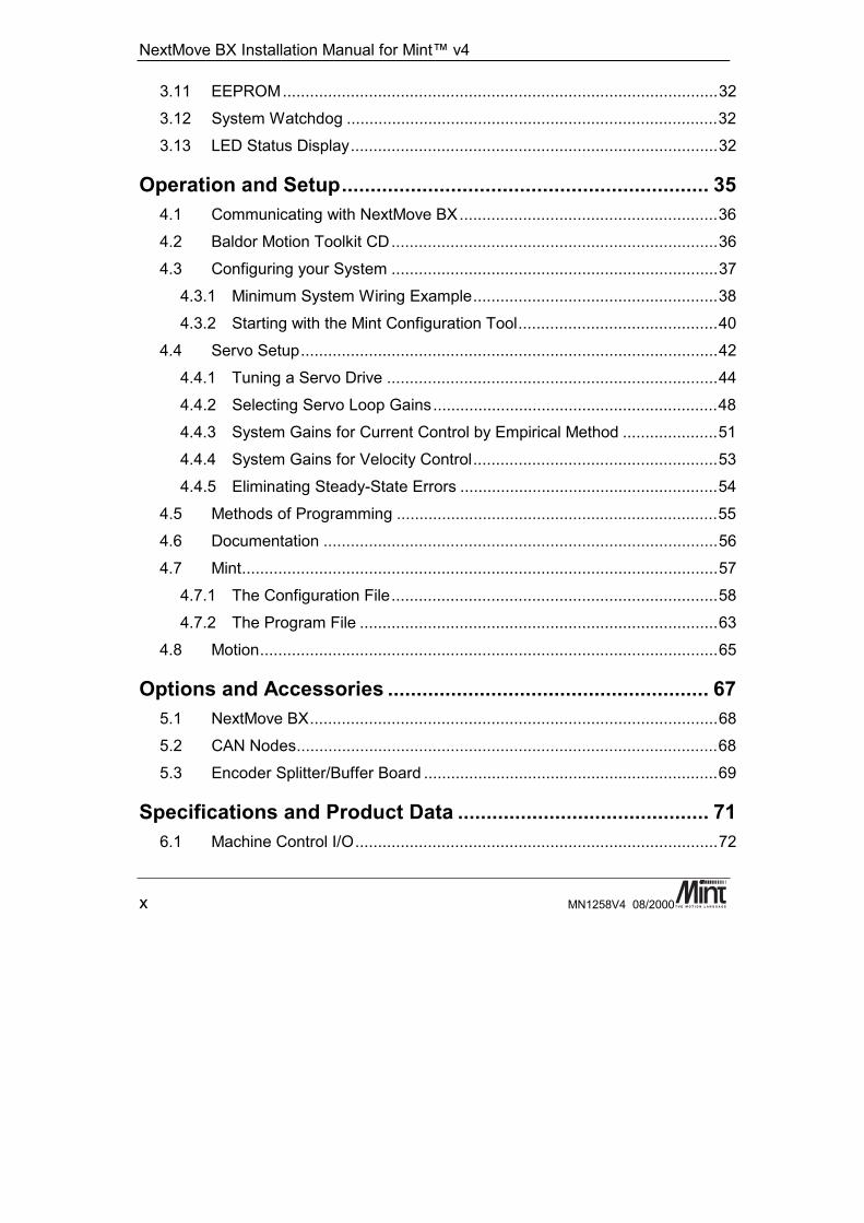
3.11 EEPROM................................................................................................323.12 System Watchdog ..................................................................................323.13 LED Status Display.................................................................................32
Operation and Setup................................................................ 354.1 Communicating with NextMove BX.........................................................364.2 Baldor Motion Toolkit CD........................................................................364.3 Configuring your System ........................................................................37
4.3.1 Minimum System Wiring Example......................................................384.3.2 Starting with the Mint Configuration Tool............................................40
4.4 Servo Setup............................................................................................424.4.1 Tuning a Servo Drive .........................................................................444.4.2 Selecting Servo Loop Gains...............................................................484.4.3 System Gains for Current Control by Empirical Method .....................514.4.4 System Gains for Velocity Control......................................................534.4.5 Eliminating Steady-State Errors .........................................................54
4.5 Methods of Programming .......................................................................554.6 Documentation .......................................................................................564.7 Mint.........................................................................................................57
4.7.1 The Configuration File........................................................................584.7.2 The Program File ...............................................................................63
4.8 Motion.....................................................................................................65
Options and Accessories ........................................................ 675.1 NextMove BX..........................................................................................685.2 CAN Nodes.............................................................................................685.3 Encoder Splitter/Buffer Board .................................................................69
Specifications and Product Data ............................................ 716.1 Machine Control I/O................................................................................72
Contents
MN1258V4 08/2000 xi
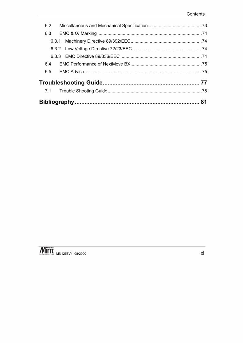
6.2 Miscellaneous and Mechanical Specification ..........................................73
6.3 EMC & CE Marking ..................................................................................74
6.3.1 Machinery Directive 89/392/EEC........................................................746.3.2 Low Voltage Directive 72/23/EEC ......................................................746.3.3 EMC Directive 89/336/EEC ................................................................74
6.4 EMC Performance of NextMove BX........................................................756.5 EMC Advice............................................................................................75
Troubleshooting Guide............................................................ 777.1 Trouble Shooting Guide..........................................................................78
Bibliography............................................................................. 81

NextMove BX Installation Manual for Mint™ v4
xii MN1258V4 08/2000

Read Me First
MN1258V4 08/2000 1
1. Read Me First
1This chapter provides an overview of the manual and symbols usedthroughout this document.
NextMove BX Installation Manual for Mint™ v4
2 MN1258V4 08/2000
This manual is intended for use with NextMove BX running Mint v4. If Mint v3 is being used, thenthe NextMove BX installation manual MN1258 should be used in preference. The hardware detailsare common between these manuals but the software references are different.
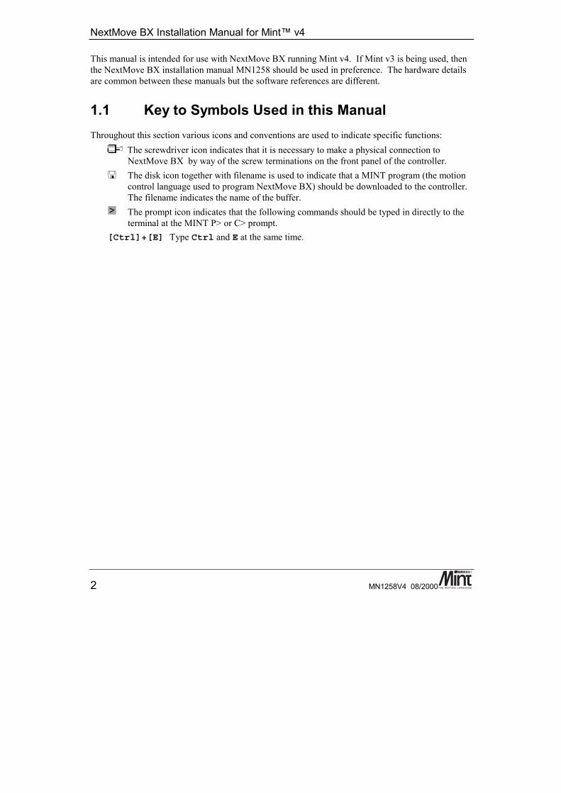
1.1 Key to Symbols Used in this ManualThroughout this section various icons and conventions are used to indicate specific functions:
The screwdriver icon indicates that it is necessary to make a physical connection toNextMove BX by way of the screw terminations on the front panel of the controller.The disk icon together with filename is used to indicate that a MINT program (the motioncontrol language used to program NextMove BX) should be downloaded to the controller.The filename indicates the name of the buffer.The prompt icon indicates that the following commands should be typed in directly to theterminal at the MINT P> or C> prompt.
[Ctrl]+[E] Type Ctrl and E at the same time.

Hardware Features
MN1258V4 08/2000 3
2. Product Overview
2A brief overview of NextMove BX and the software tools available on theBaldor Motion Toolkit.
NextMove BX Installation Manual for Mint™ v4
4 MN1258V4 08/2000
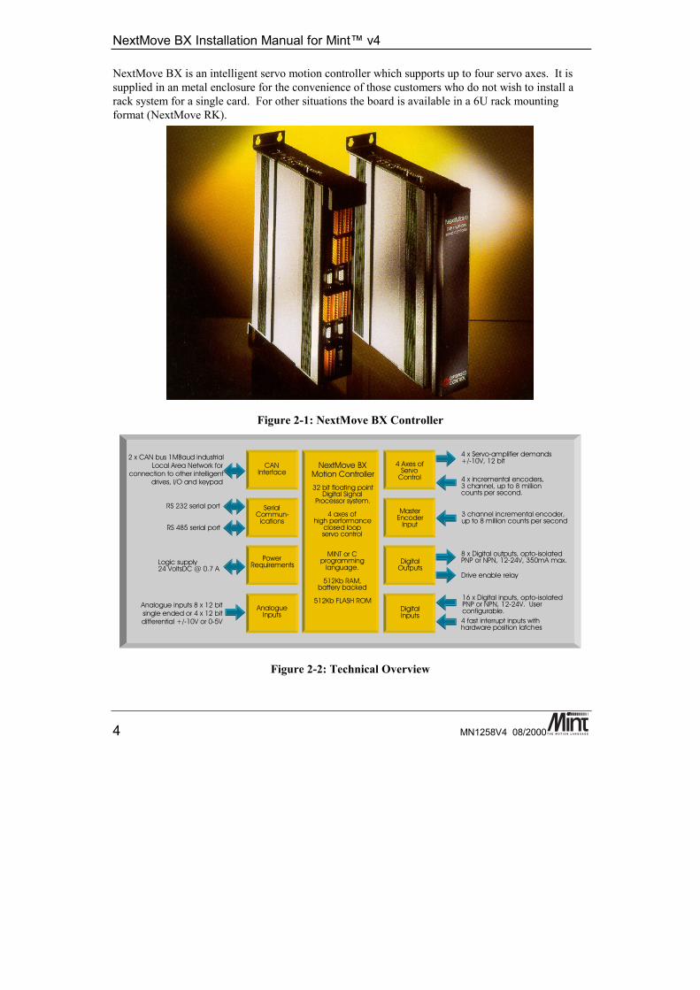
NextMove BX is an intelligent servo motion controller which supports up to four servo axes. It issupplied in an metal enclosure for the convenience of those customers who do not wish to install arack system for a single card. For other situations the board is available in a 6U rack mountingformat (NextMove RK).
Figure 2-1: NextMove BX Controller
RS 485 serial port
SerialCommun-
ications
Analogue inputs 8 x 12 bitsingle ended or 4 x 12 bitdifferential +/-10V or 0-5V
Drive enable relay
4 x Servo-amplifier demands+/-10V, 12 bit
4 x incremental encoders,3 channel, up to 8 millioncounts per second.
4 Axes ofServo
Control
NextMove BXMotion Controller
4 fast interrupt inputs withhardware position latches
CANInterface
2 x CAN bus 1MBaud industrialLocal Area Network for
connection to other intelligentdrives, I/O and keypad
MasterEncoder
Input3 channel incremental encoder,up to 8 million counts per second
DigitalOutputs
8 x Digital outputs, opto-isolatedPNP or NPN, 12-24V, 350mA max.
DigitalInputs
16 x Digital inputs, opto-isolatedPNP or NPN, 12-24V. Userconfigurable.
PowerRequirementsLogic supply
24 VoltsDC @ 0.7 A
AnalogueInputs
32 bit floating pointDigital Signal
Processor system.
4 axes ofhigh performance
closed loopservo control
MINT or Cprogramming
language.
512Kb RAM,battery backed
512Kb FLASH ROM
RS 232 serial port
Figure 2-2: Technical Overview

Hardware Features
MN1258V4 08/2000 5
NextMove BX features the MintTM v4 motion control language. Mint is a structured form of Basic,custom designed for motion control applications, either stepper or servo. It allows users to quicklyget up and running with simple motion control programs. In addition, Mint includes a wide range ofpowerful commands for complex applications.
Included with NextMove BX is the Baldor Motion Toolkit CD. This contains a number of utilitiesand useful resources to get the most from you Mint controller. These include:
Mint Configuration Tool is a rapid getting started and configuration utility designed for use with anumber of Mint v4 controllers. See the ‘Mint Configuration Tool Users Guide’ for details.
Mint WorkBench is the IDE and user interface for communicating with a Mint controller. See the‘Mint WorkBench Users Guide’ for details.
PC Developer Libraries allow PC applications to be written that communicate with Mintcontrollers. This includes C++ source and ActiveX interface. See the ‘Mint v4 PC ProgrammingGuide’ for details.
Embedded Developer Libraries allow embedded C31 applications to be developed using the TexasInstruments TMS320C3x compiler. See the ‘Mint v4 Embedded Programming Guide’ for details.
Mint Code Analyzer Tool is a utility designed to help in the process of upgrading to Mint v4. Theutility will scan existing Mint and C application files and highlight the keywords and functions thathave been changed from older firmware versions. See the ‘Mint v4 Code Analyzer Tool’ manual fordetails.

NextMove BX Installation Manual for Mint™ v4
6 MN1258V4 08/2000

Hardware Features
MN1258V4 08/2000 7
3. Hardware Guide
3This chapter describes in detail the hardware interface to the NextMoveBX controller.
NextMove BX Installation Manual for Mint™ v4
8 MN1258V4 08/2000
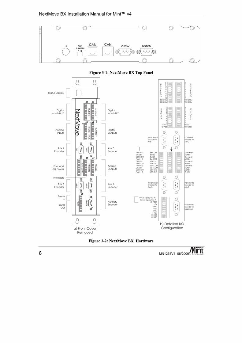
Figure 3-1: NextMove BX Top Panel
Figure 3-2: NextMove BX Hardware
Hardware Features
MN1258V4 08/2000 9
3.1 Operating EnvironmentThe safe operation of this equipment depends upon its use in the appropriate environment:
• At an altitude of ≤ 2000m (6560ft) above sea level• In an ambient temperature of 0°C to 40°C (32°F to 104°F)• In relative humidity levels of 80% for temperatures up to 31°C (87°F) decreasingly linearly
to 50% relative humidity at 40°C (104°F), non-condensing• The pollution degree according to IEC664 shall not exceed 2• The 24V dc supplied to the unit to power the control circuit shall be isolated from the mains
using double or reinforced insulation so as to constitute a safety extra low voltage supply.The inputs and outputs of control circuit shall also be confined to SELV circuits
• The atmosphere shall not contain flammable gases or vapors• There shall not be abnormal levels of nuclear radiation or X-rays• The product shall be secured by the slots in the flange, the protective earth/ground stud
shall be bonded to a safety earth/ground by a 25A conductor.
3.2 NextMove BX PCB Settings
Anti-static pre-cautions must be taken before handling the printedcircuit board (PCB).
Access to jumpers, EEPROM and other components can be achieved via a slide-down cover on theright hand side of the box. The cover is held in place by a set screw which should first be removed.A screwdriver may then be required to ease the cover free.
NextMove BX Installation Manual for Mint™ v4
10 MN1258V4 08/2000
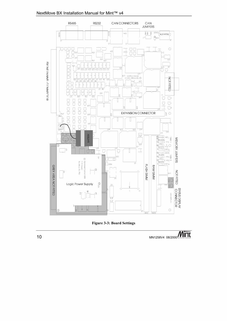
Figure 3-3: Board Settings
Hardware Features
MN1258V4 08/2000 11
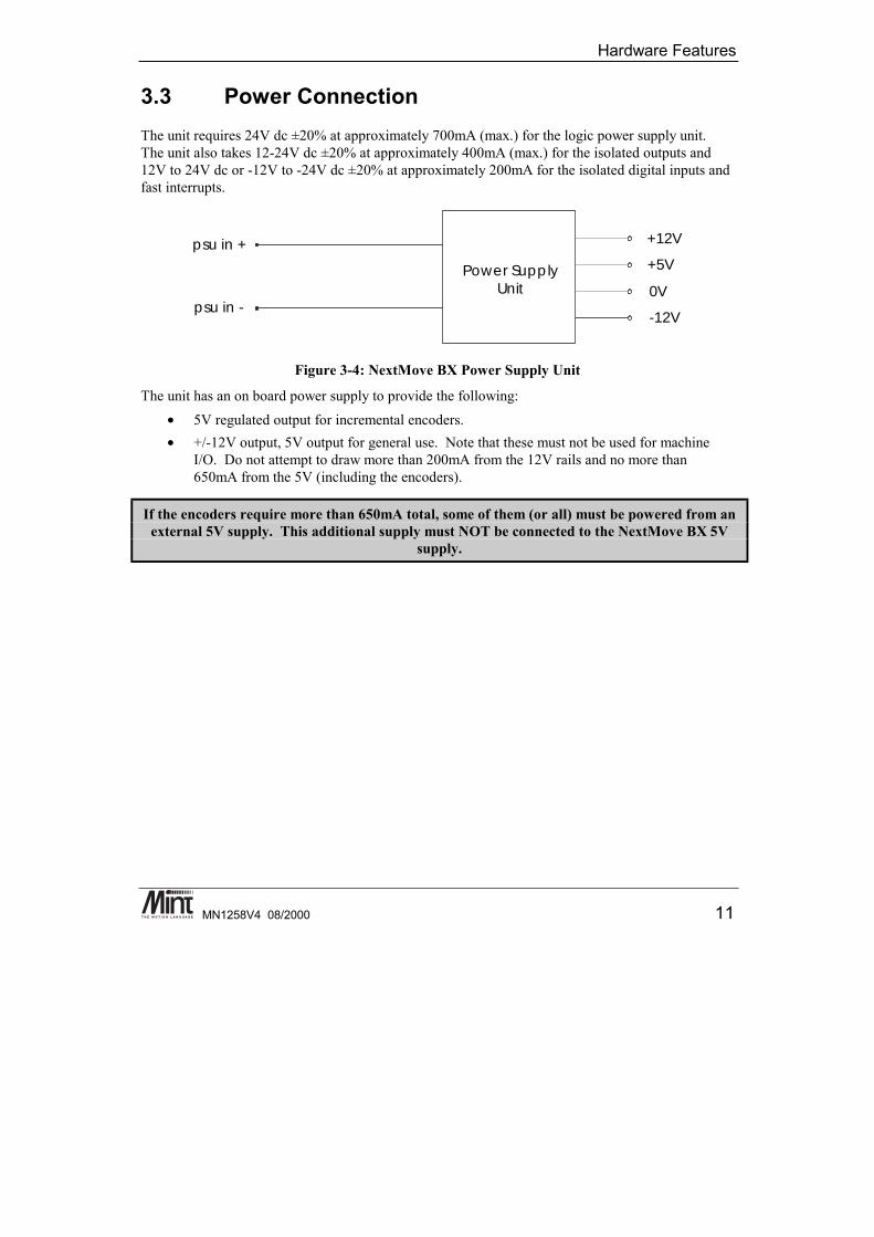
3.3 Power ConnectionThe unit requires 24V dc ±20% at approximately 700mA (max.) for the logic power supply unit.The unit also takes 12-24V dc ±20% at approximately 400mA (max.) for the isolated outputs and12V to 24V dc or -12V to -24V dc ±20% at approximately 200mA for the isolated digital inputs andfast interrupts.
psu in +
Power SupplyUnit
+12V
+5V
0V
-12Vpsu in -
Figure 3-4: NextMove BX Power Supply Unit
The unit has an on board power supply to provide the following:• 5V regulated output for incremental encoders.• +/-12V output, 5V output for general use. Note that these must not be used for machine
I/O. Do not attempt to draw more than 200mA from the 12V rails and no more than650mA from the 5V (including the encoders).
If the encoders require more than 650mA total, some of them (or all) must be powered from anexternal 5V supply. This additional supply must NOT be connected to the NextMove BX 5V
supply.

NextMove BX Installation Manual for Mint™ v4
12 MN1258V4 08/2000
3.3.1 Front Panel Power Connection: J8
Pin No Signal Function1 psu in + Power Input 24V dc (18-30V)2 psu in - Power Input 0V3 chassis Chassis ground for cable screen4 +5V Voltage output for analog circuitry @
100mA5 gnd Ground6 +12V Voltage output for analog circuitry @
50mA7 gnd Ground8 -12V Voltage output for analog circuitry @
50mA9 chassis Chassis ground for cable screen
10 chassis Chassis ground for cable screen
Two dc-dc converters are used to generate the internal logic voltages from a dc input of 24V ±20%.The logic power rails are brought out on the front panel for analog sensors and associated circuitry.These rails should not be used for machine I/O, usr-V+ and usr-gnd should be used instead.The controller has opto-isolation between the microprocessor controller and the inputs and outputs toprovide noise immunity required for industrial environments. The power supply unit inputs (24V dc)include isolated grounds.Using a power supply of 24V dc at 2A is sufficient to drive all the outputs at 50mA and with all theinputs on.
- WARNING -
Applying mains voltages to NextMove BX (110V/220V) will damage the unit. Ensure that thepower input voltages comply.

Hardware Features
MN1258V4 08/2000 13
3.4 Digital I/OThere are a total of 16 general purpose digital inputs and 8 general purpose digital outputs. Thedigital inputs are software configurable for any one of the following functions:
• Forward limit (end of travel) input on axis of the axes.• Reverse limit input on any of the axes.• home input on any of the axes.• drive error input on any of the axes.• stop input (controlled) on any of the axes.
The inputs can be programmed such that any of the axes can share the same input if necessary.The inputs are also programmable in software for being edge triggered (positive and negative) orlevel triggered (active high or low).The digital outputs can be programmed as a drive enable output for any axis or general erroroutput. Again, axes can share the same output. The active level of the output is also softwareprogrammable.As well as the general purpose I/O, NextMove BX also supports four fast position latch inputs(described in section 3.4.2).
3.4.1 Digital Inputs: J1 and J2
Connector J2:
Pin No Signal Function1 din 0 Digital input bit 02 din 1 Digital input bit 13 din 2 Digital input bit 24 din 3 Digital input bit 35 din 4 Digital input bit 46 din 5 Digital input bit 57 din 6 Digital input bit 68 din 7 Digital input bit 79 usr-com Common reference for Inputs
10 usr-com Common reference for Inputs
NextMove BX Installation Manual for Mint™ v4
14 MN1258V4 08/2000
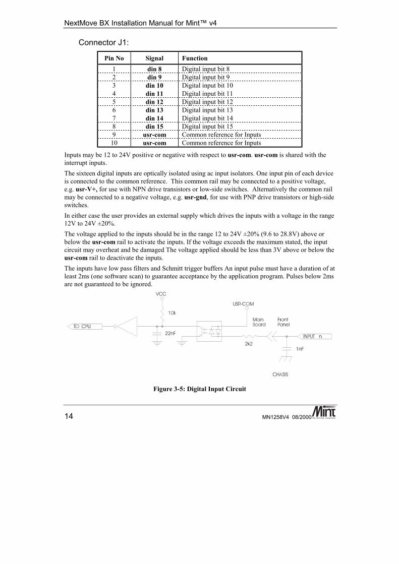
Connector J1:
Pin No Signal Function1 din 8 Digital input bit 82 din 9 Digital input bit 93 din 10 Digital input bit 104 din 11 Digital input bit 115 din 12 Digital input bit 126 din 13 Digital input bit 137 din 14 Digital input bit 148 din 15 Digital input bit 159 usr-com Common reference for Inputs
10 usr-com Common reference for Inputs
Inputs may be 12 to 24V positive or negative with respect to usr-com. usr-com is shared with theinterrupt inputs.The sixteen digital inputs are optically isolated using ac input isolators. One input pin of each deviceis connected to the common reference. This common rail may be connected to a positive voltage,e.g. usr-V+, for use with NPN drive transistors or low-side switches. Alternatively the common railmay be connected to a negative voltage, e.g. usr-gnd, for use with PNP drive transistors or high-sideswitches.In either case the user provides an external supply which drives the inputs with a voltage in the range12V to 24V ±20%.The voltage applied to the inputs should be in the range 12 to 24V ±20% (9.6 to 28.8V) above orbelow the usr-com rail to activate the inputs. If the voltage exceeds the maximum stated, the inputcircuit may overheat and be damaged The voltage applied should be less than 3V above or below theusr-com rail to deactivate the inputs.The inputs have low pass filters and Schmitt trigger buffers An input pulse must have a duration of atleast 2ms (one software scan) to guarantee acceptance by the application program. Pulses below 2msare not guaranteed to be ignored.
Figure 3-5: Digital Input Circuit
Hardware Features
MN1258V4 08/2000 15
Associated MINT keywords are:#INx, INPUTACTIVELEVEL, IN, INx, INPUTMODE, INPUTNEGTRIGGER,INPUTPOSTRIGGER, INSTATE
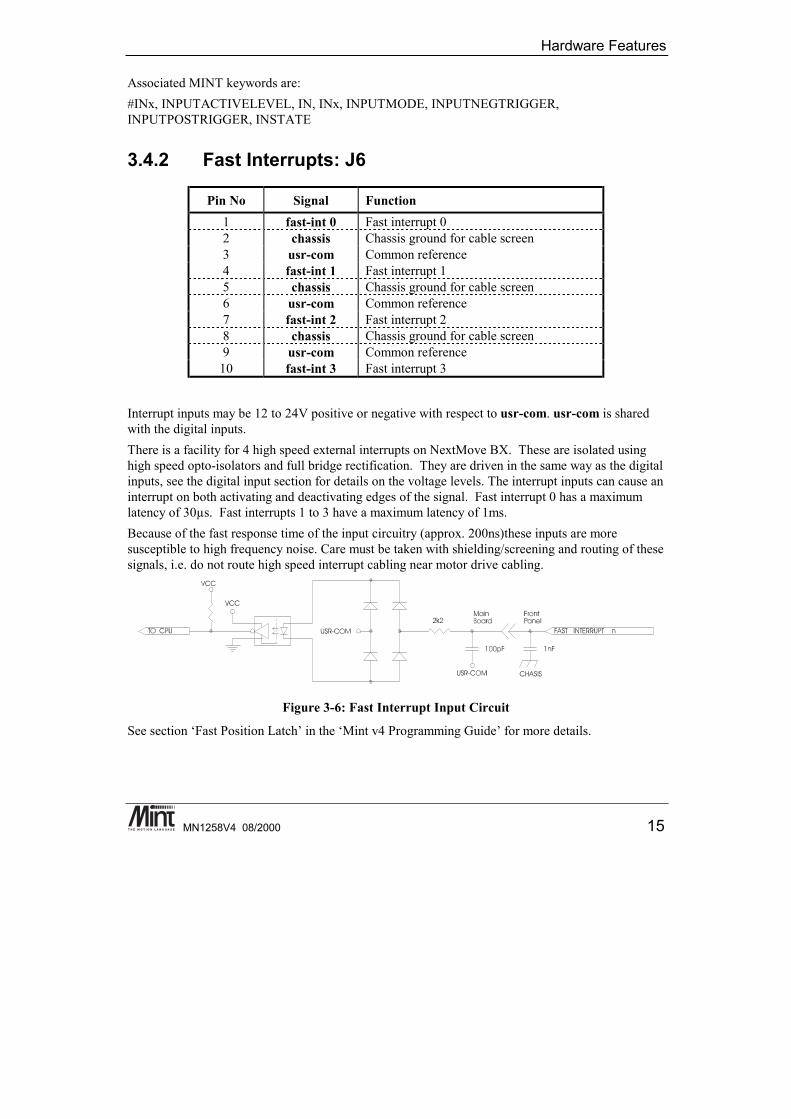
3.4.2 Fast Interrupts: J6
Pin No Signal Function1 fast-int 0 Fast interrupt 02 chassis Chassis ground for cable screen3 usr-com Common reference4 fast-int 1 Fast interrupt 15 chassis Chassis ground for cable screen6 usr-com Common reference7 fast-int 2 Fast interrupt 28 chassis Chassis ground for cable screen9 usr-com Common reference
10 fast-int 3 Fast interrupt 3
Interrupt inputs may be 12 to 24V positive or negative with respect to usr-com. usr-com is sharedwith the digital inputs.There is a facility for 4 high speed external interrupts on NextMove BX. These are isolated usinghigh speed opto-isolators and full bridge rectification. They are driven in the same way as the digitalinputs, see the digital input section for details on the voltage levels. The interrupt inputs can cause aninterrupt on both activating and deactivating edges of the signal. Fast interrupt 0 has a maximumlatency of 30µs. Fast interrupts 1 to 3 have a maximum latency of 1ms.Because of the fast response time of the input circuitry (approx. 200ns)these inputs are moresusceptible to high frequency noise. Care must be taken with shielding/screening and routing of thesesignals, i.e. do not route high speed interrupt cabling near motor drive cabling.
Figure 3-6: Fast Interrupt Input Circuit
See section ‘Fast Position Latch’ in the ‘Mint v4 Programming Guide’ for more details.
NextMove BX Installation Manual for Mint™ v4
16 MN1258V4 08/2000
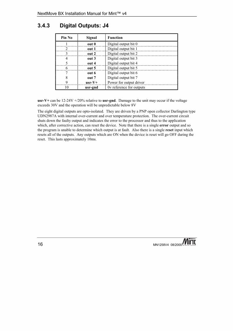
3.4.3 Digital Outputs: J4
Pin No Signal Function1 out 0 Digital output bit 02 out 1 Digital output bit 13 out 2 Digital output bit 24 out 3 Digital output bit 35 out 4 Digital output bit 46 out 5 Digital output bit 57 out 6 Digital output bit 68 out 7 Digital output bit 79 usr-V+ Power for output driver
10 usr-gnd 0v reference for outputs
usr-V+ can be 12-24V +/20% relative to usr-gnd. Damage to the unit may occur if the voltageexceeds 30V and the operation will be unpredictable below 8VThe eight digital outputs are opto-isolated. They are driven by a PNP open collector Darlington typeUDN2987A with internal over-current and over temperature protection. The over-current circuitshuts down the faulty output and indicates the error to the processor and thus to the applicationwhich, after corrective action, can reset the device. Note that there is a single error output and sothe program is unable to determine which output is at fault. Also there is a single reset input whichresets all of the outputs. Any outputs which are ON when the device is reset will go OFF during thereset. This lasts approximately 10ms.
Hardware Features
MN1258V4 08/2000 17
USR-V+
CURRENTSENSE
OUTPUT n
OUT-5V
OUT-5V
10k
10k
CONTROLLOGIC
RESET ANDERROR LOGIC
COMMON
ONEOFEIGHT
1nF
CHASIS
USR-GND MainBoard
FrontPanel
VCC1k
OUTPUT RESET
FROMCPU1k
OUTPUT ERROR1k
OUT-5V
USR-GND
USR-GND
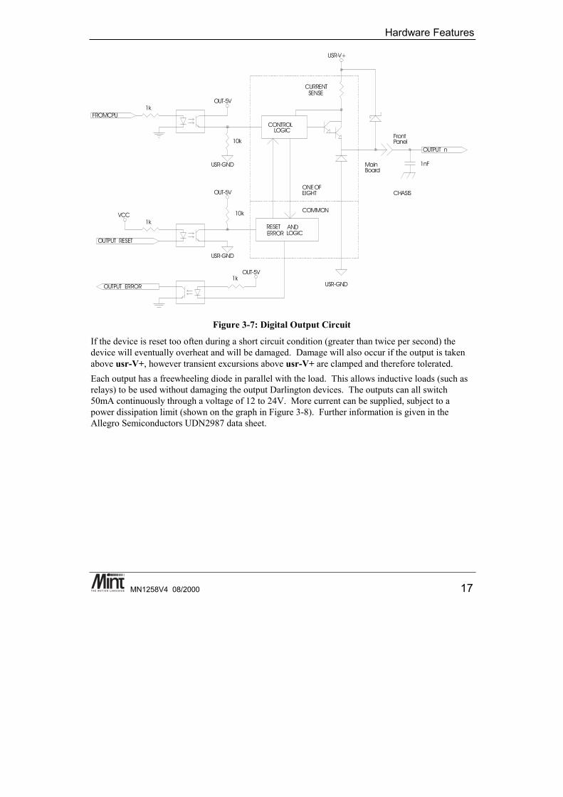
Figure 3-7: Digital Output Circuit
If the device is reset too often during a short circuit condition (greater than twice per second) thedevice will eventually overheat and will be damaged. Damage will also occur if the output is takenabove usr-V+, however transient excursions above usr-V+ are clamped and therefore tolerated.Each output has a freewheeling diode in parallel with the load. This allows inductive loads (such asrelays) to be used without damaging the output Darlington devices. The outputs can all switch50mA continuously through a voltage of 12 to 24V. More current can be supplied, subject to apower dissipation limit (shown on the graph in Figure 3-8). Further information is given in theAllegro Semiconductors UDN2987 data sheet.
NextMove BX Installation Manual for Mint™ v4
18 MN1258V4 08/2000
Number Of Outputs On Simultaneously
0
50
100
150
200
250
300
350
0 10 20 30 40 50 60 70 80 90 100
%DtCl
8765432
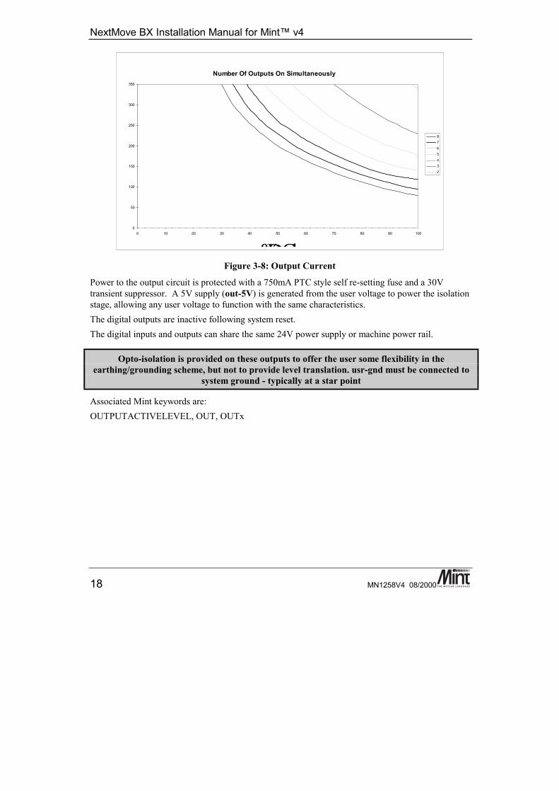
Figure 3-8: Output Current
Power to the output circuit is protected with a 750mA PTC style self re-setting fuse and a 30Vtransient suppressor. A 5V supply (out-5V) is generated from the user voltage to power the isolationstage, allowing any user voltage to function with the same characteristics.The digital outputs are inactive following system reset.The digital inputs and outputs can share the same 24V power supply or machine power rail.
Opto-isolation is provided on these outputs to offer the user some flexibility in theearthing/grounding scheme, but not to provide level translation. usr-gnd must be connected to
system ground - typically at a star point
Associated Mint keywords are:OUTPUTACTIVELEVEL, OUT, OUTx
Hardware Features
MN1258V4 08/2000 19
3.5 Analog I/O
3.5.1 Analog Inputs: J3
Pin No Signal Function1 ain 0 Analog Input 0 (differential input 0-)2 ain 1 Analog Input 1 (differential input 0+)3 ain 2 Analog Input 2 (differential input 1-)4 ain 3 Analog Input 3 (differential input 1+)5 ain 4 Analog Input 4 (differential input 2-)6 ain 5 Analog Input 5 (differential input 2+)7 ain 6 Analog Input 6 (differential input 3-)8 ain 7 Analog Input 7 (differential input 3+)9 agnd 0v reference for analog circuit
10 chassis Chassis ground for cable screen
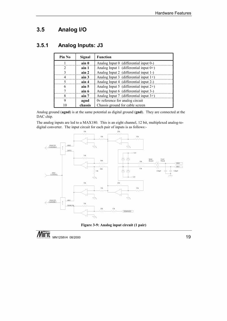
Analog ground (agnd) is at the same potential as digital ground (gnd). They are connected at theDAC chip.The analog inputs are led to a MAX180. This is an eight channel, 12 bit, multiplexed analog-to-digital converter. The input circuit for each pair of inputs is as follows:-
Figure 3-9: Analog input circuit (1 pair)
NextMove BX Installation Manual for Mint™ v4
20 MN1258V4 08/2000
NextMove BX uses a Data Acquisition Chip (Maxim MAX180). This device has:• 12 bit resolution with ½ LSB linearity• Built in track and hold• A 2us sample window.
The chip can operate with either bipolar or unipolar input voltages, the selection of which is madeunder software control.Input buffers with an impedance of 20k and clamping diodes protect the device from voltageextremes, and analog switches allow true differential measurement. The voltage range of the inputswhen used in single-ended mode is ±2.5V (bipolar) or 0-5V (unipolar), and when used in differentialmode is ±10V (bipolar only).The input buffers do not have any filtering. Therefore any noise on the inputs will be reflected in thevalue read.When analog channel 0 (2, 4, 6) is switched to differential mode, channel 1(3, 5, 7) is switched tofeed back of analog output 0 (1, 2, 3).Associated MINT keywords are:ADCMODE, ADC
3.5.2 Analog Outputs (Drive Command: J7)The controller provides up to four ±10V (±0.1%) analog outputs for motor command – one for eachservo axis. A 14 bit DAC is used which gives a resolution of 1.2mV/bit. The optimum cablingarrangement is to use a separate shielded twisted pair cable, twist command+ with command- andconnect the screen/shield to screen/shield at the controller end only.
Pin No Signal Function1 demand 0 Demand/Command output for axis 02 agnd Analog ground3 demand 1 Demand/Command output for axis 14 agnd Analog ground5 demand 2 Demand/Command output for axis 26 agnd Analog ground7 demand 3 Demand/Command output for axis 38 agnd Analog ground9 agnd Analog ground
10 chassis Chassis ground for cable screen
Analog ground (agnd) is at the same potential as digital ground (gnd). They are connected at theDAC chip.There are four 14 bit resolution analog outputs implemented in an MP7611. The outputs have arange of ± 10V, and revert to 0V during system reset. The outputs are referred to the system ground(not opto-isolated) via a separate but connected analog ground plane.
Hardware Features
MN1258V4 08/2000 21
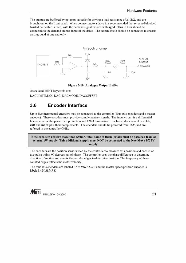
The outputs are buffered by op-amps suitable for driving a load resistance of ≥10kΩ, and arebrought out on the front panel. When connecting to a drive it is recommended that screened/shieldedtwisted pair cable is used, with the demand signal twisted with agnd. This in turn should beconnected to the demand 'minus' input of the drive. The screen/shield should be connected to chassisearth/ground at one end only.
Figure 3-10: Analogue Output Buffer
Associated MINT keywords are:DACLIMITMAX, DAC, DACMODE, DACOFFSET
3.6 Encoder InterfaceUp to five incremental encoders may be connected to the controller (four axis encoders and a masterencoder). These encoders must provide complementary signals. The input circuit is a differentialline receiver with open circuit protection and 120Ω termination. Each encoder channel has chA,chB and index plus their complements. The encoders should be powered from +5V, and arereferred to the controller GND.
If the encoders require more than 650mA total, some of them (or all) must be powered from anexternal 5V supply. This additional supply must NOT be connected to the NextMove BX 5V
supply.
The encoders are the position sensors used by the controller to measure axis position and consist oftwo pulse trains, 90 degrees out of phase. The controller uses the phase difference to determinedirection of motion and counts the encoder edges to determine position. The frequency of thesecounted edges reflects the motor velocity.The four axis encoders are labeled AXIS 0 to AXIS 3 and the master speed/position encoder islabeled AUXILIARY.
NextMove BX Installation Manual for Mint™ v4
22 MN1258V4 08/2000
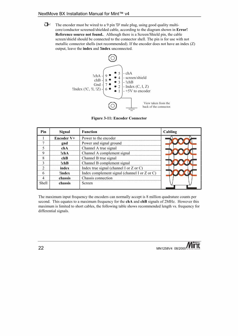
The encoder must be wired to a 9 pin 'D' male plug, using good quality multi-core/conductor screened/shielded cable, according to the diagram shown in Error!Reference source not found.. Although there is a Screen/Shield pin, the cablescreen/shield should be connected to the connector shell. The pin is for use with notmetallic connector shells (not recommended). If the encoder does not have an index (Z)output, leave the index and !index unconnected.
Figure 3-11: Encoder Connector
Pin Signal Function Cabling1 Encoder V+ Power to the encoder7 gnd Power and signal ground5 chA Channel A true signal9 !chA Channel A complement signal8 chB Channel B true signal3 !chB Channel B complement signal2 index Index true signal (channel I or Z or C)6 !index Index complement signal (channel I or Z or C)4 chassis Chassis connection
Shell chassis Screen
The maximum input frequency the encoders can normally accept is 8 million quadrature counts persecond. This equates to a maximum frequency for the chA and chB signals of 2MHz. However thismaximum is limited to short cables, the following table shows recommended length vs. frequency fordifferential signals.
Hardware Features
MN1258V4 08/2000 23
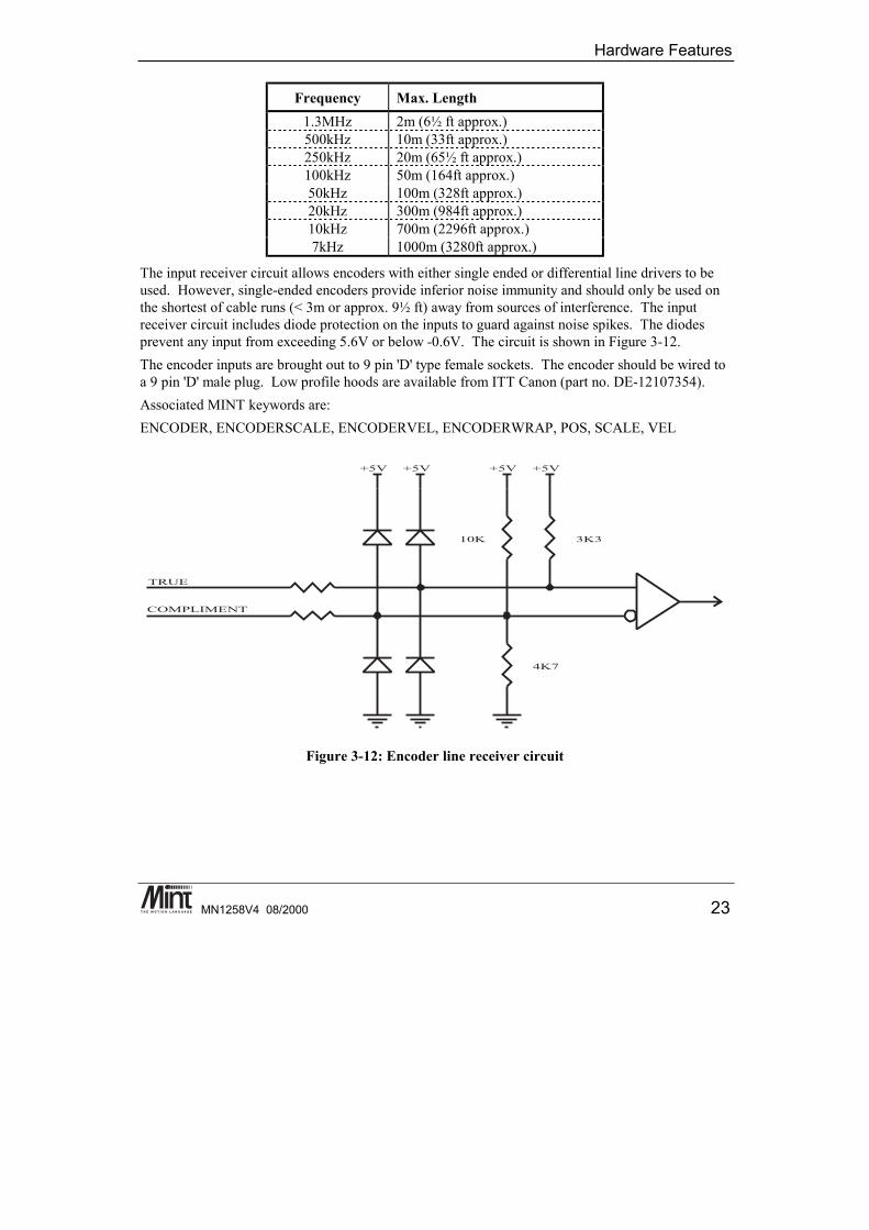
Frequency Max. Length1.3MHz 2m (6½ ft approx.)500kHz 10m (33ft approx.)250kHz 20m (65½ ft approx.)100kHz 50m (164ft approx.)50kHz 100m (328ft approx.)20kHz 300m (984ft approx.)10kHz 700m (2296ft approx.)7kHz 1000m (3280ft approx.)
The input receiver circuit allows encoders with either single ended or differential line drivers to beused. However, single-ended encoders provide inferior noise immunity and should only be used onthe shortest of cable runs (< 3m or approx. 9½ ft) away from sources of interference. The inputreceiver circuit includes diode protection on the inputs to guard against noise spikes. The diodesprevent any input from exceeding 5.6V or below -0.6V. The circuit is shown in Figure 3-12.The encoder inputs are brought out to 9 pin 'D' type female sockets. The encoder should be wired toa 9 pin 'D' male plug. Low profile hoods are available from ITT Canon (part no. DE-12107354).Associated MINT keywords are:ENCODER, ENCODERSCALE, ENCODERVEL, ENCODERWRAP, POS, SCALE, VEL
Figure 3-12: Encoder line receiver circuit
NextMove BX Installation Manual for Mint™ v4
24 MN1258V4 08/2000
3.7 Relay: J5The relay connections on the connector are shown as the shaded boxes.
Pin No Signal Function1 err-com Relay common contact2 err-nc Relay normally closed contact3 err-no Relay normally open contact4 err-com Relay common contact5 usr-V+ Power rail for digital output driver6 usr-V+ Power rail for digital output driver7 usr-com Common reference for digital inputs8 usr-com Common reference for digital inputs9 usr-com 0v reference for digital output driver
10 usr-com 0v reference for digital output driver
A single pole, change-over relay is included on the card to provide a volt-free contact for theenabling of other parts of the system, such as drives. The relay is controlled by a latch which iscleared during reset of the unit. Reset occurs on power up or power down, watchdog error and 5Vunder-voltage. The relay is energized only by software control. The relay is the default global erroroutput channel.
Because of the track rating on the PCB, the relay is limited to a rating of 500mA at 24V dc.For this reason, the relay should be used for voltage free signal switching and should not be
used for power.
Associated MINT keywords are:RELAY, DRIVEENABLEOUTPUT, GLOBALERROROUTPUT
3.8 Serial PortsThe unit is fitted with a DUART providing one RS232 port and one RS485 port. The serial ports areset up for the following configuration by default:
• 9600 Baud• 1 start bit• 8 data bits• 1 stop bit• No parity• RTS/CTS Hardware handshaking disabled (RS232 port only)
Hardware Features
MN1258V4 08/2000 25
The baud rate of both ports is user-configurable with the RS232 capable of 19,200 and the RS485 upto 9,600. Hardware handshaking (RTS / CTS) is permanently enabled. Both serial ports are broughtout on the top of the unit on 9 pin 'D'-type connectors.
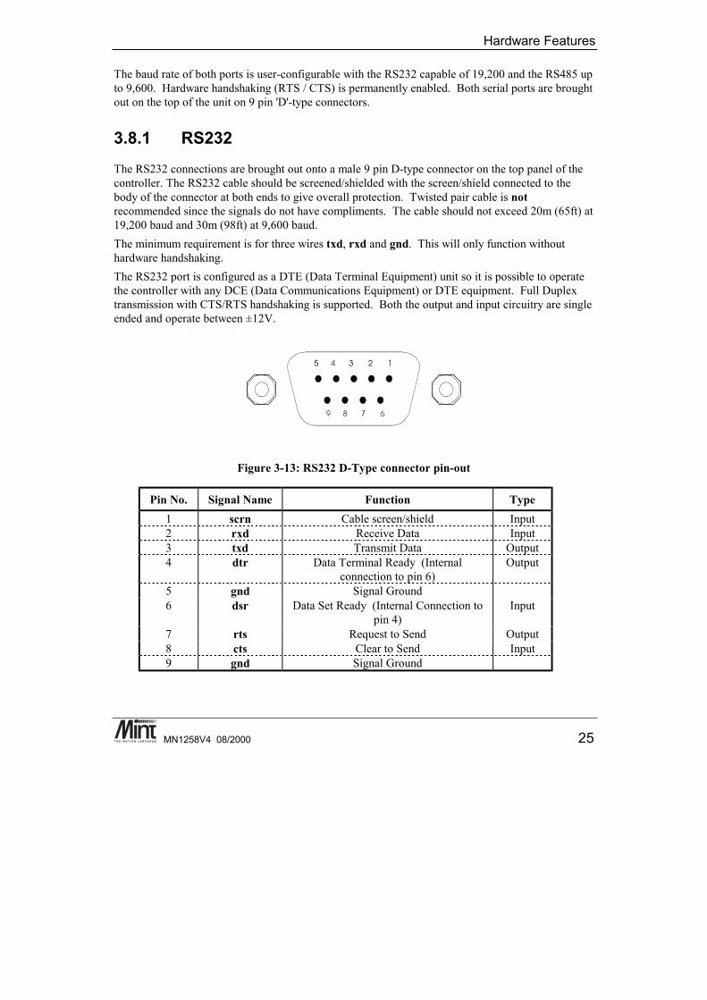
3.8.1 RS232The RS232 connections are brought out onto a male 9 pin D-type connector on the top panel of thecontroller. The RS232 cable should be screened/shielded with the screen/shield connected to thebody of the connector at both ends to give overall protection. Twisted pair cable is notrecommended since the signals do not have compliments. The cable should not exceed 20m (65ft) at19,200 baud and 30m (98ft) at 9,600 baud.The minimum requirement is for three wires txd, rxd and gnd. This will only function withouthardware handshaking.The RS232 port is configured as a DTE (Data Terminal Equipment) unit so it is possible to operatethe controller with any DCE (Data Communications Equipment) or DTE equipment. Full Duplextransmission with CTS/RTS handshaking is supported. Both the output and input circuitry are singleended and operate between ±12V.
Figure 3-13: RS232 D-Type connector pin-out
Pin No. Signal Name Function Type1 scrn Cable screen/shield Input2 rxd Receive Data Input3 txd Transmit Data Output4 dtr Data Terminal Ready (Internal
connection to pin 6)Output
5 gnd Signal Ground6 dsr Data Set Ready (Internal Connection to
pin 4)Input
7 rts Request to Send Output8 cts Clear to Send Input9 gnd Signal Ground
NextMove BX Installation Manual for Mint™ v4
26 MN1258V4 08/2000
The following table shows the wiring required for a standard PC 25 pin or 9 pin connector:
ControllerPin No.
Signal Name Function Wire to:25 Pin
Wire to:9 Pin
1 scrn Cable screen/shield - -2 rxd Receive Data 2 33 txd Transmit Data 3 24 dtr Data Terminal Ready (Internal
connection to pin 6)6 6
5 gnd Signal Ground 7 56 dsr Data Set Ready (Internal
Connection to pin 4)20 4
7 rts Request to Send 5 88 cts Clear to Send 4 79 gnd Signal Ground 7 9
Associated MINT keywords are:SERIALBAUD
3.8.2 RS485The RS485 connections are brought out onto a male 9-way D-type connector on the top of the unit.These signals are not isolated. The RS485 cable should be a screened/shielded twisted pair with atleast two pairs and ground. The screen should be connected to the body of the connector at bothends to give overall protection. The maximum cable length is 1000m (3280ft) at 9,600 baud un-terminated or 1200m (3937ft) with terminators.The RS485 supports a full multi-drop protocol. Both the output and input signals are differential andoperate between 0 and 5V.
Hardware Features
MN1258V4 08/2000 27
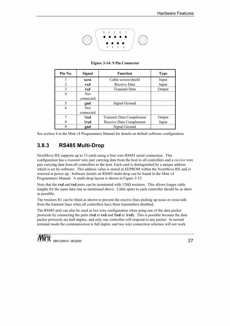
Figure 3-14: 9 Pin Connector
Pin No. Signal Function Type1 scrn Cable screen/shield Input2 rxd Receive Data Input3 txd Transmit Data Output4 Not
connected5 gnd Signal Ground6 Not
connected7 !txd Transmit Data Complement Output8 !rxd Receive Data Complement Input9 gnd Signal Ground
See section 4 in the Mint v4 Programmers Manual for details on default software configuration.
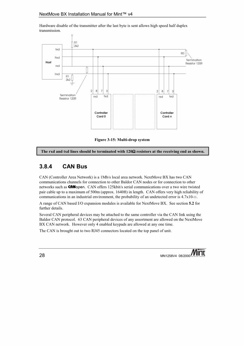
3.8.3 RS485 Multi-DropNextMove BX supports up to 15 cards using a four wire RS485 serial connection. Thisconfiguration has a transmit wire pair carrying data from the host to all controllers and a receive wirepair carrying data from all controllers to the host. Each card is distinguished by a unique addresswhich is set by software. This address value is stored in EEPROM within the NextMove BX and isrestored at power up. Software details on RS485 multi-drop can be found in the Mint v4Programmers Manual. A multi-drop layout is shown in Figure 3-15.Note that the rxd and txd pairs can be terminated with 120Ω resistors. This allows longer cablelengths for the same data rate as mentioned above. Cable spurs to each controller should be as shortas possible.The resisters R1 can be fitted as shown to prevent the receive lines picking up noise or cross-talkfrom the transmit lines when all controllers have there transmitters disabled.The RS485 port can also be used in two wire configuration when using one of the data packetprotocols by connecting the pairs (txd to rxd and !txd to !rxd). This is possible because the datapacket protocols are half duplex, and only one controller will respond to any packet. In normalterminal mode the communication is full duplex and two wire connection schemes will not work.
NextMove BX Installation Manual for Mint™ v4
28 MN1258V4 08/2000
Hardware disable of the transmitter after the last byte is sent allows high speed half duplextransmission.
Figure 3-15: Multi-drop system
The rxd and txd lines should be terminated with 120ΩΩΩΩ resistors at the receiving end as shown.
3.8.4 CAN BusCAN (Controller Area Network) is a 1Mb/s local area network. NextMove BX has two CANcommunications channels for connection to other Baldor CAN nodes or for connection to othernetworks such as CANopen. CAN offers 125kbit/s serial communications over a two wire twistedpair cable up to a maximum of 500m (approx. 1640ft) in length. CAN offers very high reliability ofcommunications in an industrial environment, the probability of an undetected error is 4.7x10-11.A range of CAN based I/O expansion modules is available for NextMove BX. See section 5.2 forfurther details.Several CAN peripheral devices may be attached to the same controller via the CAN link using theBaldor CAN protocol. 63 CAN peripheral devices of any assortment are allowed on the NextMoveBX CAN network. However only 4 enabled keypads are allowed at any one time.The CAN is brought out to two RJ45 connectors located on the top panel of unit.
Hardware Features
MN1258V4 08/2000 29
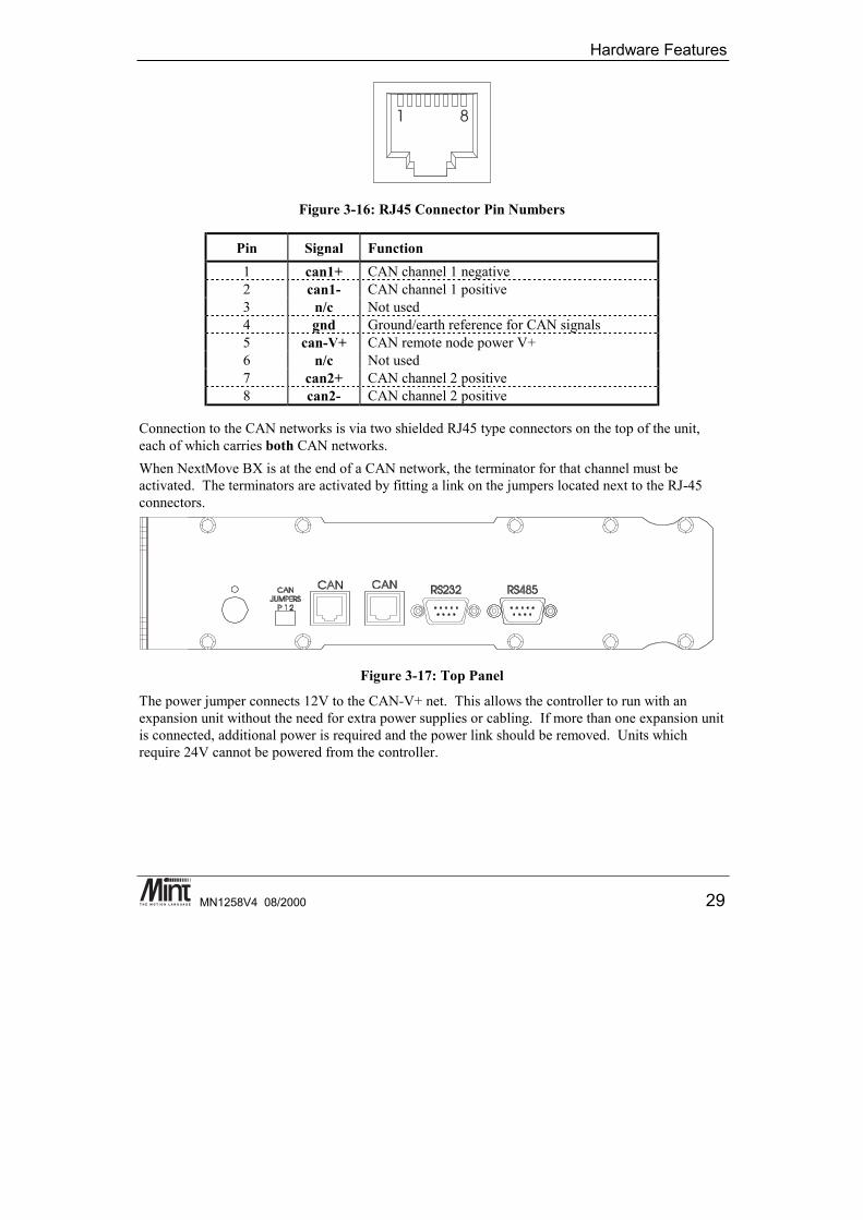
Figure 3-16: RJ45 Connector Pin Numbers
Pin Signal Function1 can1+ CAN channel 1 negative2 can1- CAN channel 1 positive3 n/c Not used4 gnd Ground/earth reference for CAN signals5 can-V+ CAN remote node power V+6 n/c Not used7 can2+ CAN channel 2 positive8 can2- CAN channel 2 positive
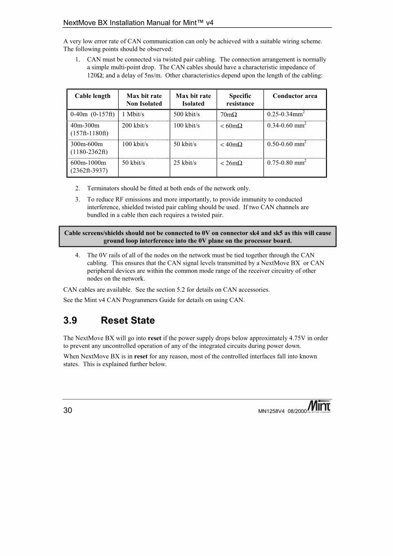
Connection to the CAN networks is via two shielded RJ45 type connectors on the top of the unit,each of which carries both CAN networks.When NextMove BX is at the end of a CAN network, the terminator for that channel must beactivated. The terminators are activated by fitting a link on the jumpers located next to the RJ-45connectors.
Figure 3-17: Top Panel
The power jumper connects 12V to the CAN-V+ net. This allows the controller to run with anexpansion unit without the need for extra power supplies or cabling. If more than one expansion unitis connected, additional power is required and the power link should be removed. Units whichrequire 24V cannot be powered from the controller.
NextMove BX Installation Manual for Mint™ v4
30 MN1258V4 08/2000
A very low error rate of CAN communication can only be achieved with a suitable wiring scheme.The following points should be observed:
1. CAN must be connected via twisted pair cabling. The connection arrangement is normallya simple multi-point drop. The CAN cables should have a characteristic impedance of120Ω; and a delay of 5ns/m. Other characteristics depend upon the length of the cabling:
Cable length Max bit rateNon Isolated
Max bit rateIsolated
Specificresistance
Conductor area
0-40m (0-157ft) 1 Mbit/s 500 kbit/s 70mΩ 0.25-0.34mm2
40m-300m(157ft-1180ft)
200 kbit/s 100 kbit/s < 60mΩ 0.34-0.60 mm2
300m-600m(1180-2362ft)
100 kbit/s 50 kbit/s < 40mΩ 0.50-0.60 mm2
600m-1000m(2362ft-3937)
50 kbit/s 25 kbit/s < 26mΩ 0.75-0.80 mm2
2. Terminators should be fitted at both ends of the network only.
3. To reduce RF emissions and more importantly, to provide immunity to conductedinterference, shielded twisted pair cabling should be used. If two CAN channels arebundled in a cable then each requires a twisted pair.
Cable screens/shields should not be connected to 0V on connector sk4 and sk5 as this will causeground loop interference into the 0V plane on the processor board.
4. The 0V rails of all of the nodes on the network must be tied together through the CANcabling. This ensures that the CAN signal levels transmitted by a NextMove BX or CANperipheral devices are within the common mode range of the receiver circuitry of othernodes on the network.
CAN cables are available. See the section 5.2 for details on CAN accessories.See the Mint v4 CAN Programmers Guide for details on using CAN.
3.9 Reset StateThe NextMove BX will go into reset if the power supply drops below approximately 4.75V in orderto prevent any uncontrolled operation of any of the integrated circuits during power down.When NextMove BX is in reset for any reason, most of the controlled interfaces fall into knownstates. This is explained further below.
Hardware Features
MN1258V4 08/2000 31
CommunicationsDuring reset CAN controller will have no effect on the CAN bus. If a reset occurs during thetransmission of a message CAN errors are likely to occur.When the controller goes into a reset state all serial communications will be terminated immediately,this may result in incomplete or corrupted messages.Digital OutputsAll of the digital outputs are inactive on power up regardless of their polarity. They will return to theinactive state whenever reset occurs.Analog OutputsAll analog outputs are set to 0V by hardware during power-up and will return to 0V on a reset.However the output buffer circuit may have a small offset and so the actual voltage seen at the outputmay not be zero.
3.10 Battery Backup of MemoryThe RAM is backed up with a battery to prevent loss of data when the main power is removed.Switching from the main power (VCC) to the battery power (VBAT) is done by the reset chip whenVCC falls below VBAT. The power consumption of this switch is 1µA maximum at roomtemperature.The backup battery is a 3 cell nickel metal hydride (NiMH) with a nominal voltage of 3.6V(1.2V/cell) and a capacity of 280mAh. A standard low power 0.5Mbyte SIMM requiresapproximately 1.2µA at 3.0V for data retention. This, coupled with the consumption of the batteryswitch, gives a total consumption of 2.2µA. Theoretically this would give a data retention time of14 years. However, the self discharge characteristics of the battery mean that it will drop to 60%charge in 6 months at 20°C. Memory contents will be retained down to 95% discharge which takesapproximately 3 years. This self discharge is faster at higher temperatures, at 45°C the battery willdrop to approximately 45% charge in 1 month giving a data retention time of only 4 months. Shouldthe battery become very discharged, it is recommended that it be removed and fully rechargedoutside the unit since its maximum capacity will have been reduced to about 80% of nominal.
3.10.1 Changing the BatteryAccess to the battery is gained by removing the 2 screws at the bottom of the rear vertical extrusionand the opposing screws at the top of the extrusion. The extrusion and the side plate can then beremoved giving access to the PCB. Once the PCB is exposed the battery can be removed by cuttingthe restraining cable tie and disconnecting it from the main board. Replacement batteries and cableties can be obtained from.When the battery is disconnected the program and other data held in RAM may be corrupted or lost.It is therefore advisable to back up all data on the controller before changing the battery.
Never attempt to open the unit while it is powered.

NextMove BX Installation Manual for Mint™ v4
32 MN1258V4 08/2000
3.10.2 Charging the BatteryThe charge state of the backup battery will not be known when the unit is first delivered. To fullyrecharge the battery using the built in trickle charge will take a maximum of approximately 80 hours.
3.11 EEPROMNextMove BX has 8k bytes of EEPROM, most of which is used for the processor boot code. Theremaining space (about 2k bytes) is used for non-volatile storage of other parameters such as thebaud rate of the two serial ports, the card number in multi-card systems and the product count.Access to this memory is via specific keywords within Mint and is not available for generalvariables.
3.12 System WatchdogThe system watchdog is a hardware protection method so that in the event of a firmware or ‘C’program malfunction, the controller is put into software reset.
3.13 LED Status DisplayThe LED display on the front panel of the NextMove BX provides an indication of the status of thecontroller. The following symbols will be seen during normal operation:
Display Meaning1-F Running MINT, serial node number of the
controller is displayed in hex. (1 – 15).M Running MINT, serial node number of the
controller is 0 or greater than 15.
When the controller is turned on, the following sequence will be seen:
Display Meaningall segments Board in reset.
B Booting.J Starting Mint firmware.
M or 1-F Firmware is running.

Hardware Features
MN1258V4 08/2000 33
When updating firmware on the controller, the following sequence will be seen. When update iscomplete, the boot sequence above should be seen.
Display MeaningR Performing RAM test.F Erasing FLASH memory.L Updating firmware.
The following symbols are error conditions. Errors are denoted by the flashing of the ‘dot’ on thedisplay at approximately 10Hz. If the following conditions are seen, please contact technicalsupport.
Display MeaningD DUART (serial driver) failure.C CAN failure.S Memory not detected correctly.R Memory failed test.F Failed to erase FLASH.E Firmware update was not successful.U Cannot detect firmware. Try updating firmware again.

NextMove BX Installation Manual for Mint™ v4
34 MN1258V4 08/2000
Getting Started
MN1258V4 08/2000 35
4. Operation and Setup
4This chapter is step by step guide to setting up a NextMove BX servocontrol system. Basic familiarity with PC’s and the Windows environmentis assumed.
Introduction to servo systems and tuning. Determining system gains andfine-tuning.
NextMove BX Installation Manual
36 MN1258V4 08/2000
4.1 Communicating with NextMove BXIn order to communicate with NextMove BX, a RS232 or RS485 connection must be made to an ATstyle personal computer. The Baldor Motion Toolkit CD supports the following operating systemsonly: Windows 95, Windows 98 and Windows NT version 4.The RS232 or RS485 cable is used to connect the controller to a computer for programming andsystem commissioning. A computer is not essential for operation of the controller, but is requiredfor programming. A standard serial cable should be used or built according to the wiring diagram insection 3.8. An RS232 cable is available (order code CBL001-501).
Please note that the RS232 specification is a 'standard' that varies from manufacturer tomanufacturer and therefore not all RS232 cables will work with the controller.
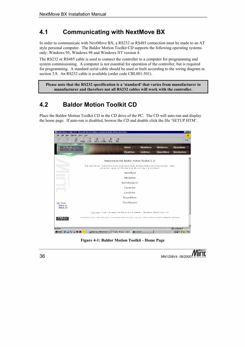
4.2 Baldor Motion Toolkit CDPlace the Baldor Motion Toolkit CD in the CD drive of the PC. The CD will auto-run and displaythe home page. If auto-run is disabled, browse the CD and double click the file ‘SETUP.HTM’.
Figure 4-1: Baldor Motion Toolkit - Home Page
Getting Started
MN1258V4 08/2000 37
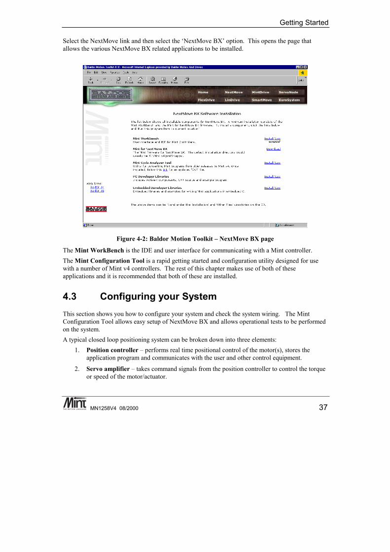
Select the NextMove link and then select the ‘NextMove BX’ option. This opens the page thatallows the various NextMove BX related applications to be installed.
Figure 4-2: Baldor Motion Toolkit – NextMove BX page
The Mint WorkBench is the IDE and user interface for communicating with a Mint controller.The Mint Configuration Tool is a rapid getting started and configuration utility designed for usewith a number of Mint v4 controllers. The rest of this chapter makes use of both of theseapplications and it is recommended that both of these are installed.
4.3 Configuring your SystemThis section shows you how to configure your system and check the system wiring. The MintConfiguration Tool allows easy setup of NextMove BX and allows operational tests to be performedon the system.A typical closed loop positioning system can be broken down into three elements:
1. Position controller – performs real time positional control of the motor(s), stores theapplication program and communicates with the user and other control equipment.
2. Servo amplifier – takes command signals from the position controller to control the torqueor speed of the motor/actuator.

NextMove BX Installation Manual
38 MN1258V4 08/2000
3. Motor/actuator – translates electrical power from the servo amplifier into rotary or linearmovement. The motor is fitted with a position sensor that feeds the output position back tothe controller.
The controller works by sampling the position of the motor at regular intervals and comparing thisposition with its target position. It then instructs the amplifier to drive the motor to correct anypositional error. This process is repeated typically 1000 times per second to ensure that the motor isalways in the correct position.
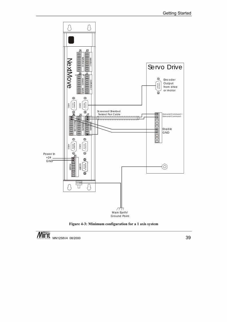
4.3.1 Minimum System Wiring ExampleThe following section is a guide to setting up a minimum system. A minimum system is one wherethe controller and drives are configured to work with as little external wiring as possible. It isrecommended that motors are tested and set up ‘on the bench’ and not within the machine.This step-by-step example covers setting-up a system with one servo axis. Figure 4-3 is a simplifiedwiring diagram for the system mentioned above. It should be noted that this is not the only possibleconfiguration. It is important to read the associated text before attempting the set-up. For detailedwiring information, see section Error! Reference source not found..
Getting Started
MN1258V4 08/2000 39
sss
INPUTS 0-7
INPUTS 8-15
OUTPUTS 0-7
ANALO
G
INPUTS
AXIS 0
AXIS 1
DEM
AND
S
INTERRUPTS
RELAY &
CAN
AXIS 2
AXIS 3
MA
STER
POW
ER
ss
sN
extM
ove
Servo Drive
Encoder Outputfrom drive or motor
Demand/Command Demand/Command -
+
EnableGND
Screened/Shielded Twisted Pair Cable
Power In+24GND
Main Earth/Ground Point
J1
J3
J5
Figure 4-3: Minimum configuration for a 1 axis system
NextMove BX Installation Manual
40 MN1258V4 08/2000
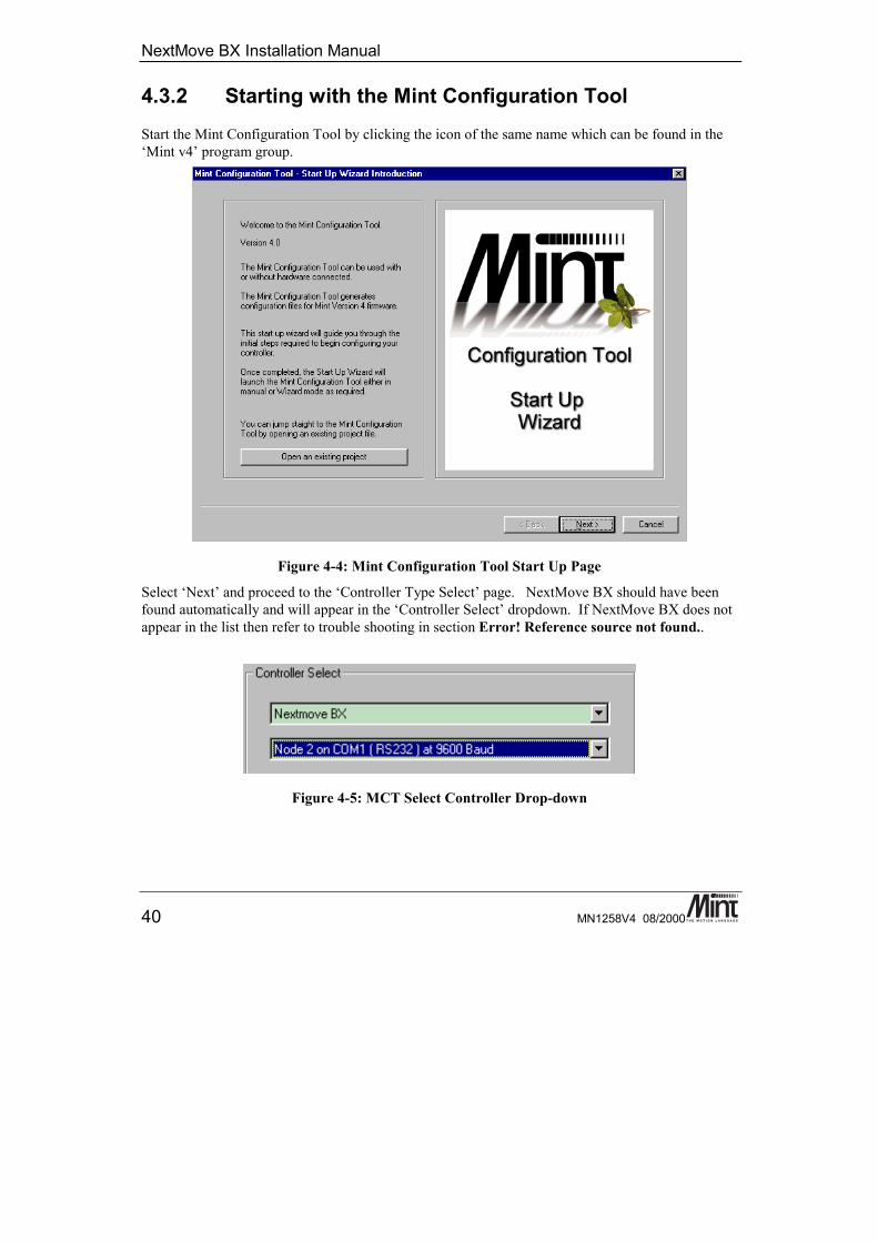
4.3.2 Starting with the Mint Configuration ToolStart the Mint Configuration Tool by clicking the icon of the same name which can be found in the‘Mint v4’ program group.
Figure 4-4: Mint Configuration Tool Start Up Page
Select ‘Next’ and proceed to the ‘Controller Type Select’ page. NextMove BX should have beenfound automatically and will appear in the ‘Controller Select’ dropdown. If NextMove BX does notappear in the list then refer to trouble shooting in section Error! Reference source not found..
Figure 4-5: MCT Select Controller Drop-down
Getting Started
MN1258V4 08/2000 41
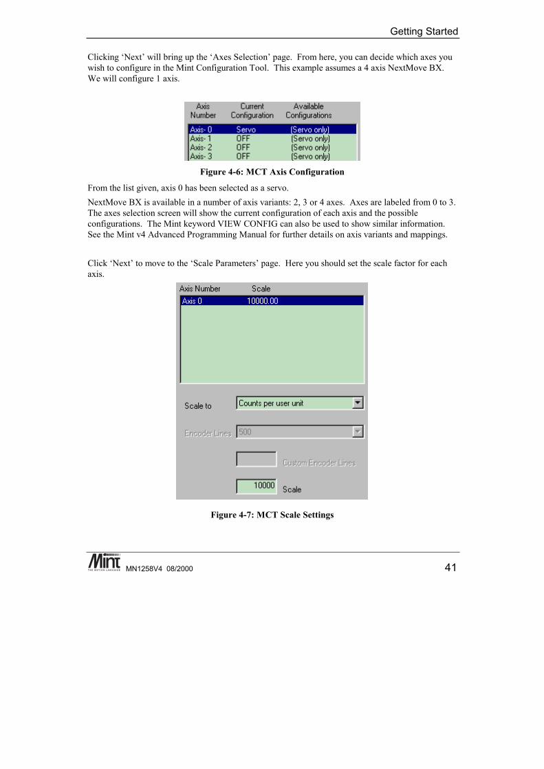
Clicking ‘Next’ will bring up the ‘Axes Selection’ page. From here, you can decide which axes youwish to configure in the Mint Configuration Tool. This example assumes a 4 axis NextMove BX.We will configure 1 axis.
Figure 4-6: MCT Axis Configuration
From the list given, axis 0 has been selected as a servo.NextMove BX is available in a number of axis variants: 2, 3 or 4 axes. Axes are labeled from 0 to 3.The axes selection screen will show the current configuration of each axis and the possibleconfigurations. The Mint keyword VIEW CONFIG can also be used to show similar information.See the Mint v4 Advanced Programming Manual for further details on axis variants and mappings.
Click ‘Next’ to move to the ‘Scale Parameters’ page. Here you should set the scale factor for eachaxis.
Figure 4-7: MCT Scale Settings
NextMove BX Installation Manual
42 MN1258V4 08/2000
Mint defines all positional and speed related motion keywords in terms of encoder quadrature countsfor servo motors or steps for stepper motors. The scale factor allows the system to be scaled to yourown units to suit your application. The diagram below shows the effect of scaling on positionalinformation:
Figure 4-8: The Effect of Scaling on Positional Information
In an XY application, for example, you may want to define all positions in millimeters or inches.For each servo axis, either manually enter a scale factor for ‘Counts per user unit’ or select ‘Countsper revolution’ and select the number of lines on the encoder.
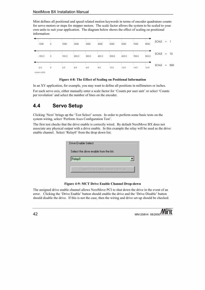
4.4 Servo SetupClicking ‘Next’ brings up the ‘Test Select’ screen. In order to perform some basic tests on thesystem wiring, select ‘Perform Axes Configuration Test’.The first test checks that the drive enable is correctly wired. By default NextMove BX does notassociate any physical output with a drive enable. In this example the relay will be used as the driveenable channel. Select ‘Relay0’ from the drop down list.
Figure 4-9: MCT Drive Enable Channel Drop-down
The assigned drive enable channel allows NextMove PCI to shut down the drive in the event of anerror. Clicking the ‘Drive Enable’ button should enable the drive and the ‘Drive Disable’ buttonshould disable the drive. If this is not the case, then the wiring and drive set-up should be checked.
Getting Started
MN1258V4 08/2000 43
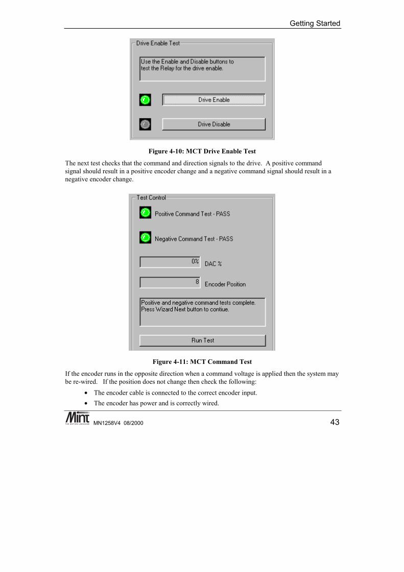
Figure 4-10: MCT Drive Enable Test
The next test checks that the command and direction signals to the drive. A positive commandsignal should result in a positive encoder change and a negative command signal should result in anegative encoder change.
Figure 4-11: MCT Command Test
If the encoder runs in the opposite direction when a command voltage is applied then the system maybe re-wired. If the position does not change then check the following:
• The encoder cable is connected to the correct encoder input.• The encoder has power and is correctly wired.
NextMove BX Installation Manual
44 MN1258V4 08/2000
If the motor does not move, check the following:• The amplifier is enabled.• There is a voltage output from the command+ output.
4.4.1 Tuning a Servo DriveAt the lowest level of control software, instantaneous axis position demands produced by thecontroller software must be translated into motor demands. This is achieved by closed loop controlof the motor. The motor is controlled to minimize the error between demand and actual positionmeasured with an incremental encoder.Every 1ms (or optionally 500us or 250us using the LOOPTIME keyword) the controller comparesdesired and actual positions and calculates the correct demand for the motor. The corrective signalis calculated by a PIDVFA (Proportional, Integral, Derivative, Velocity Feedback, Velocity Feedforward and Acceleration Feed forward) algorithm.Control could be achieved by applying a signal proportional to the error alone, but this is a rathersimplistic approach. Imagine that there is a small error between demanded and actual position. Aproportional controller will simply multiply the error by some constant and apply the result to themotor via an amplifier. If the gain is too low, then the motor will not hold positional. As the gain isincreased, the motor will present more resistance to positional error, but oscillations will increase inmagnitude until the system becomes unstable.
Getting Started
MN1258V4 08/2000 45
time
velocity
acceleration/deceleration rateACCEL
0
axis speed during moveSPEED
units ofmeasureset bySCALE
Ideal trapezoidal velocity profile
time
velocity
0
Typical actual velocity profile
Overshoot
Following error (positional lag)
UnderdampedGoodIdeal
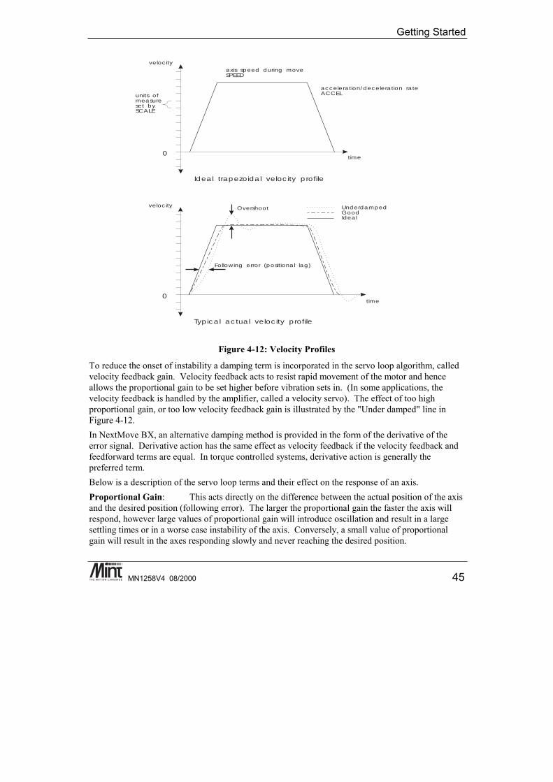
Figure 4-12: Velocity Profiles
To reduce the onset of instability a damping term is incorporated in the servo loop algorithm, calledvelocity feedback gain. Velocity feedback acts to resist rapid movement of the motor and henceallows the proportional gain to be set higher before vibration sets in. (In some applications, thevelocity feedback is handled by the amplifier, called a velocity servo). The effect of too highproportional gain, or too low velocity feedback gain is illustrated by the "Under damped" line inFigure 4-12.In NextMove BX, an alternative damping method is provided in the form of the derivative of theerror signal. Derivative action has the same effect as velocity feedback if the velocity feedback andfeedforward terms are equal. In torque controlled systems, derivative action is generally thepreferred term.Below is a description of the servo loop terms and their effect on the response of an axis.Proportional Gain: This acts directly on the difference between the actual position of the axisand the desired position (following error). The larger the proportional gain the faster the axis willrespond, however large values of proportional gain will introduce oscillation and result in a largesettling times or in a worse case instability of the axis. Conversely, a small value of proportionalgain will result in the axes responding slowly and never reaching the desired position.
NextMove BX Installation Manual
46 MN1258V4 08/2000
Derivative Gain: This acts on the rate of change of following error. This term will speedup the response of an axis to the initial change in demand and reduce overshoot. As this term acts onthe rate of change of following error when the axis is stationary the control effort generated by thederivative term should be zero. However in reality as servo axes are never truly at rest a large valueof derivative gain will cause the axis to oscillate. In a worse case, the derivative term can introduceoscillation during motion which can lead to instability in the axis.Integral Gain: This acts on the accumulated following error so that the steady state followingerror of an axis may be reduced to zero. This term is generally slow to respond as accumulatedfollowing error takes time to become large enough to be significant in the servo loop. Using a largevalue of integral gain will cause oscillation and instability in the axis. Most servo axes are verysensitive to integral gain and generally can only cope with a very small value. Because of this, thesize of the demand caused by the integral term can be limited which allows a larger value to be usedwithout fear of introducing instability during motion.Velocity Feedback: This acts on the actual velocity of the axis. This term provides dampingand will slug the response of the axis. This helps in reducing overshoot. If the effect of the velocityfeedback term is dominant in the control law this will lead to instability in the axis.Velocity Feedforward: This acts on the demand velocity as generated by the profiler. As suchthis term cannot introduce steady state instability. This term can be used to pull in any followingerror when the axis is moving at a constant velocity.Acceleration Feedforward: This acts on the demand acceleration as generated by theprofiler. As with velocity feedforward this term cannot introduce steady state instability. This termcan be used to pull in any following error when the axis is moving at a constant acceleration.Two types of servo amplifiers may be used with the controller:1. Current or torque amplifiers use the demand signal to control the current flowing in the motor
armature and hence the torque of the motor.2. Velocity controlled amplifiers (velocity servo) use the demand signal as a servo speed reference.For general purpose applications, the torque amplifier is cheaper and simpler to set up, but thevelocity servo gives better control, especially in high performance applications. For torqueamplifiers, velocity feedback must be used to stabilize the system, but this is not normally requiredfor a velocity servo since it incorporates its own internal velocity feedback.A block diagram of the complete control loop, showing controller, amplifier, motor and gearbox ispresented below. The amplifier / servo may be a simple current amplifier, or incorporate internalvelocity feedback via a tachometer.
Getting Started
MN1258V4 08/2000 47
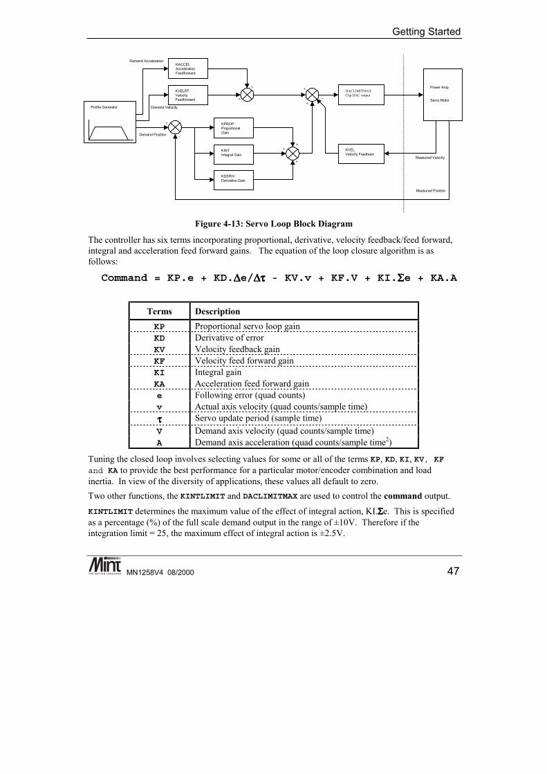
Figure 4-13: Servo Loop Block Diagram
The controller has six terms incorporating proportional, derivative, velocity feedback/feed forward,integral and acceleration feed forward gains. The equation of the loop closure algorithm is asfollows:
Command = KP.e + KD.∆∆∆∆e/∆∆∆∆ττττ - KV.v + KF.V + KI.ΣΣΣΣe + KA.A
Terms DescriptionKP Proportional servo loop gainKD Derivative of errorKV Velocity feedback gainKF Velocity feed forward gainKI Integral gainKA Acceleration feed forward gaine Following error (quad counts)v Actual axis velocity (quad counts/sample time)ττττ Servo update period (sample time)V Demand axis velocity (quad counts/sample time)A Demand axis acceleration (quad counts/sample time2)
Tuning the closed loop involves selecting values for some or all of the terms KP, KD, KI, KV, KFand KA to provide the best performance for a particular motor/encoder combination and loadinertia. In view of the diversity of applications, these values all default to zero.Two other functions, the KINTLIMIT and DACLIMITMAX are used to control the command output.
KINTLIMIT determines the maximum value of the effect of integral action, KI.ΣΣΣΣe. This is specifiedas a percentage (%) of the full scale demand output in the range of ±10V. Therefore if theintegration limit = 25, the maximum effect of integral action is ±2.5V.
KVELFFVelocityFeedforward
Profile Generator
KACCELAccelerationFeedforward
KPROPProportionalGain
KINTIntegral Gain
KDERIVDerivative Gain
DACLIMITMAXClip DAC output
+
Power Amp
Servo Motor
KVELVelocity Feedback
-
-
+
+ +
+
+
+
+
Measured Velocity
Demand Position
Demand Velocity
Demand Acceleration
Measured Position
NextMove BX Installation Manual
48 MN1258V4 08/2000
DACLIMITMAX determines the maximum value of the demand output as a percentage of the full scaledemand. Therefore if DACLIMITMAX = 50, the maximum demand output will be ±5V.Tuning terms can be controlled in Mint using the following keywords:
Keyword Abbreviation DescriptionDACLIMITMAX DCX Limit maximum DAC output
KPROP KP Proportional gainKDERIV KD Derivative gainKINT KI Integral servo loop gain
KINTMODE KIM Integration mode during motionKINTLIMIT KIL Range limit for integrator % of max DAC output
KVEL KV Velocity feedback gainKVELFF KF Velocity feedforward gainKACCEL KA Acceleration feedforward gain
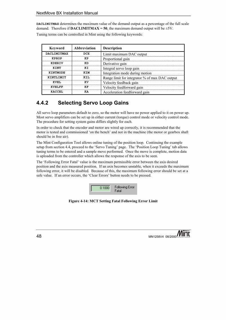
4.4.2 Selecting Servo Loop GainsAll servo loop parameters default to zero, so the motor will have no power applied to it on power up.Most servo amplifiers can be set up in either current (torque) control mode or velocity control mode.The procedure for setting system gains differs slightly for each.In order to check that the encoder and motor are wired up correctly, it is recommended that themotor is tested and commissioned ‘on the bench’ and not in the machine (the motor or gearbox shaftshould be in free air).The Mint Configuration Tool allows online tuning of the position loop. Continuing the examplesetup from section 4.4, proceed to the ‘Servo Tuning’ page. The ‘Position Loop Tuning’ tab allowstuning terms to be entered and a sample move performed. Once the move is complete, motion datais uploaded from the controller which allows the response of the axis to be seen.The ‘Following Error Fatal’ value is the maximum permissible error between the axis desiredposition and the axis measured position. If an axis becomes unstable, when it exceeds the maximumfollowing error, it will be disabled. Because of this, the maximum following error should be set at asafe value. If an error occurs, the ‘Clear Errors’ button needs to be pressed.
Figure 4-14: MCT Setting Fatal Following Error Limit
Getting Started
MN1258V4 08/2000 49
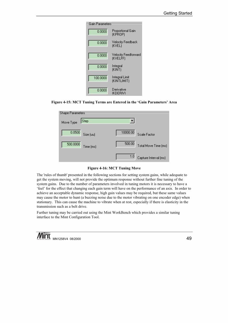
Figure 4-15: MCT Tuning Terms are Entered in the ‘Gain Parameters’ Area
Figure 4-16: MCT Tuning Move
The 'rules of thumb' presented in the following sections for setting system gains, while adequate toget the system moving, will not provide the optimum response without further fine tuning of thesystem gains. Due to the number of parameters involved in tuning motors it is necessary to have a‘feel’ for the effect that changing each gain term will have on the performance of an axis. In order toachieve an acceptable dynamic response, high gain values may be required, but these same valuesmay cause the motor to hunt (a buzzing noise due to the motor vibrating on one encoder edge) whenstationary. This can cause the machine to vibrate when at rest, especially if there is elasticity in thetransmission such as a belt drive.Further tuning may be carried out using the Mint WorkBench which provides a similar tuninginterface to the Mint Configuration Tool.
NextMove BX Installation Manual
50 MN1258V4 08/2000
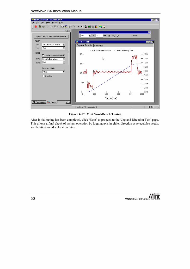
Figure 4-17: Mint WorkBench Tuning
After initial tuning has been completed, click ‘Next’ to proceed to the ‘Jog and Direction Test’ page.This allows a final check of system operation by jogging axis in either direction at selectable speeds,acceleration and deceleration rates.
Getting Started
MN1258V4 08/2000 51
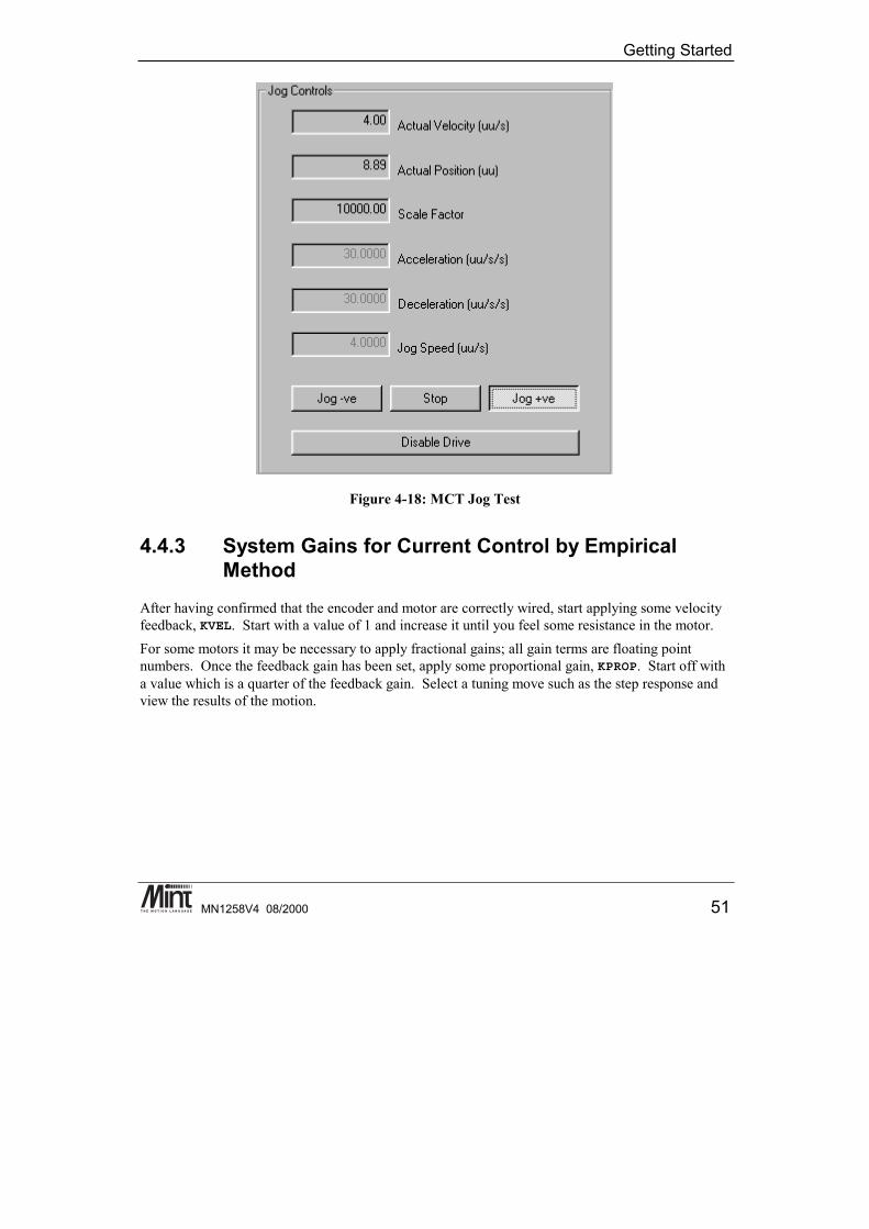
Figure 4-18: MCT Jog Test
4.4.3 System Gains for Current Control by EmpiricalMethod
After having confirmed that the encoder and motor are correctly wired, start applying some velocityfeedback, KVEL. Start with a value of 1 and increase it until you feel some resistance in the motor.For some motors it may be necessary to apply fractional gains; all gain terms are floating pointnumbers. Once the feedback gain has been set, apply some proportional gain, KPROP. Start off witha value which is a quarter of the feedback gain. Select a tuning move such as the step response andview the results of the motion.
NextMove BX Installation Manual
52 MN1258V4 08/2000
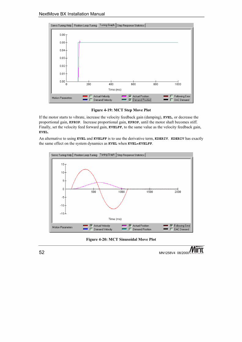
Figure 4-19: MCT Step Move Plot
If the motor starts to vibrate, increase the velocity feedback gain (damping), KVEL, or decrease theproportional gain, KPROP. Increase proportional gain, KPROP, until the motor shaft becomes stiff.Finally, set the velocity feed forward gain, KVELFF, to the same value as the velocity feedback gain,KVEL.An alternative to using KVEL and KVELFF is to use the derivative term, KDERIV. KDERIV has exactlythe same effect on the system dynamics as KVEL when KVEL=KVELFF.
Figure 4-20: MCT Sinusoidal Move Plot

Getting Started
MN1258V4 08/2000 53
4.4.4 System Gains for Velocity ControlVelocity controlled drives incorporate the velocity feedback term in the amplifier which providessystem damping and therefore it is usually sufficient to have KVEL = KDERIV = 0 on thecontroller. Usually, the value of the proportional gain, KPROP, will be less than with an equivalentcurrent controlled system. Often a fractional value of proportional gain gives the best response. Forexample KPROP=0.1 compared with 2 for current controlled drives.Correct setting of the velocity feed forward gain, KVELFF, is important to get maximum responsefrom the system. This is best performed using a storage oscilloscope (or the NextMove WorkBench)to record the tachometer output for fast point-to-point moves. This enables velocity/time profile forthe motor to be seen in order to monitor actual acceleration and overshoot.Referring to the servo loop block diagram, the velocity feed forward term is a block, which takes theinstantaneous speed demand from the profile generator and adds this to the output block. BecauseKVELFF is a feed forward term, a very important difference between this and the other terms exists.KVELFF is outside the closed loop and therefore does not have an effect on system stability. Thismeans that the term can be increased to maximum without causing the motor to oscillate, providedthat the other terms are set-up correctly.In practice however, a very high value of KVELFF is of no benefit to system performance. Instead, itshould be set such that a demand of x RPM from the profile generator results in a demand output tothe velocity drive, which gives x RPM on the motor shaft (a 1:1 relationship).When set-up correctly, KVELFF will cause the motor to move at the demand speed from the profilegenerator. This is true without the PID terms in the closed loop doing anything except compensatingfor small errors in the position of the motor due to analog drift. This gives faster response tochanges in demand speed, with lower following errors.
Example calculation of KVELFF:In order to calculate the correct value for KVELFF, you need to consider the workings of the servoloop closure algorithms. In the servo loop, speeds are expressed in quadrature counts/servo loopclosure time. For instance, a speed of 100 is 100 counts every 1ms with NextMove PCI (note thatthe default loop closure time is 1ms).In this example the velocity of the servo is 3000RPM with a +10V input, and the encoder has 1000counts per revolution.At 3000RPM we require an analog voltage of +10V. 3000RPM relates to:
300060
50= revs per second
NextMove BX Installation Manual
54 MN1258V4 08/2000
Now the number of quadrature counts per loop closure time can be calculated by using theexpression:
speed in rev per sec * encoder line count * 4number of loop closures per second
The factor of 4 is included since the controller counts every edge of the pulse train coming from theencoder A and B channels, which gives four times better resolution than the number of lines.
50 1000 4 1000 200* * / = quadrature counts per servo lop closure time
The DAC output has a resolution of 12 bits over the range -10V to +10V, therefore +10V = 2048counts.The feed forward term is therefore given by:
KVELFF = =2048200
10 24.
Increasing KVELFF above the calculated value will cause the controller to have a following errorahead of the desired position. Decreasing KVELFF below this value will cause the controller to havea more normal following error behind the desired position. The calculated value above should givezero following error in normal running.It is possible to investigate the effect of velocity feed forward gain by jogging the motor at constantspeed and monitoring the axis following error for different values of KVELFF. When attempting this,make sure that there is zero integral gain since this will cause the following error to tend to zerounder steady state conditions, thereby negating the effect of changes in KVELFF.
4.4.5 Eliminating Steady-State ErrorsIn systems where precise positioning accuracy is required, it is often necessary to position to withinone encoder count. Proportional gain, KPROP, is not normally able to achieve this because a verysmall following error will only produce a small demand for the amplifier which may not be enoughto overcome mechanical friction (this is particularly so for current controlled systems). This errorcan be overcome by applying some integral gain.The integral gain, KINT, works by accumulating following error over time to produce a demandsufficient to move the motor into the zero following error position. KINT can therefore alsoovercome errors caused by gravitational effects, such as vertically moving linear tables, where withcurrent controlled drives, a non-zero command output is required to achieve zero following error.Particular care is required when setting KINT since a high value can cause instability during moves.The effect of KINT should be limited by setting the maximum range of the integration (KINTLIMIT)to the minimum value that is sufficient to overcome friction or static loads.

Getting Started
MN1258V4 08/2000 55
Typical values are:KINTLIMIT = 5KINT = 0.1
where KINTLIMIT limits the integral term to 5% of the full DAC output range. KINT is usually afactor of 10 less than proportional gain, KPROP. With NextMove PCI, the integrator can be set tooperate in various modes:1. The integrator is always applied.2. The integrator is only applied during periods of constant velocity.3. The integrator is only applied when the axis is at rest.This functionality is set using the KINTMODE keyword.
4.5 Methods of ProgrammingNextMove BX can be programmed using several different languages. These are:
Language Location of Program DescriptionMint On Controller Basic style language supplied with
controller.Embedded C On Controller ANSI C compiled and linked using the
Texas Instruments C31 compiler tolibraries supplied by Baldor.
Visual C/C++ On Host PC Microsoft Visual C/C++ compiled inconjunction with source code or COMserver supplied by Baldor.
Visual Basic On Host PC Microsoft Visual Basic using COMserver supplied by Baldor.
Delphi On Host PC Inprise Delphi using COM serversupplied by Baldor.
All methods of programming are based around the same command set. In general all commands maybe called from any language, thus giving the user maximum programming flexibility.For example, to load a move of 10 user units on axis zero:
Language CommandMint MOVEA.0 = 10
Embedded C setMoveA (0,10);
Visual C/C++ myPCI.setMoveA (0, 10);
Visual Basic myPCI.setMoveA 0, 10
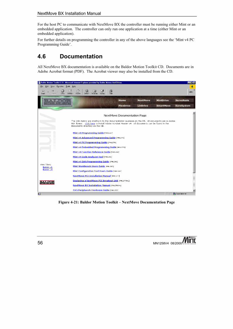
NextMove BX Installation Manual
56 MN1258V4 08/2000
For the host PC to communicate with NextMove BX the controller must be running either Mint or anembedded application. The controller can only run one application at a time (either Mint or anembedded application).For further details on programming the controller in any of the above languages see the ‘Mint v4 PCProgramming Guide’.
4.6 DocumentationAll NextMove BX documentation is available on the Baldor Motion Toolkit CD. Documents are inAdobe Acrobat format (PDF). The Acrobat viewer may also be installed from the CD.
Figure 4-21: Baldor Motion Toolkit – NextMove Documentation Page
Getting Started
MN1258V4 08/2000 57
4.7 MintMint is a structured form of Basic which has been custom designed for motion control applications.The Mint language has been written to allow users to get started quickly with simple motionprograms and also provides a wide range of more powerful commands for complex applications.Mint is used in thousands of applications worldwide, servicing many high demand industries such astextiles and packaging. Applications range from simple single axis applications to complex multi-axis, multi-controller applications via a host-controlled link. It is Mint's flexible and powerfulcommand set that is able to provide a solution to the vast number of industrial motion controlapplications.In addition to usual Basic type commands such as PRINT, FOR..NEXT and IF..THEN, Minthas a number of keywords dedicated to motion control and input/output.Mint also provides full control over basic motor control parameters such as servo loop gains inaddition to all the digital and analog I/O on the controller.Mint splits motion keywords into 2 categories; motion variables and motion commands. Motionvariables are keywords that set axis parameters. These can be read or written (although notnecessarily both). Motion commands initiate motion. For example:
SPEED[0,1] = 10,20 : REM Set slew speed on axes 0 and 1ACCEL[0,1] = 100,200 : REM Set acceleration on axes 0 and 1MOVER[0,1] = 50,100 : REM Load positional movesGO[0,1] : REM Start motion
The use of the square brackets controls 2 axes in the system, where axis 0 is the first axis followedby axis 1 and so on. The use of the square brackets is optional as Mint is very flexible in its multi-axis syntax. In this example, axis 0 is set up with a speed of 10 units/s, acceleration of 100 units/s2
and a relative move of 50 units. Axis 1 is set up with a speed of 20 units/s, acceleration of 200units/s2 and a relative move of 100 units. SPEED, ACCEL and MOVER are all motion variables. Themotion command GO is used to initiate motion. Most motion keywords can be abbreviated to 2 or 3letters, for example, SPEED can be replaced with SP and MOVER replaced with MR. This saves bothon code space and typing. The example above could be abbreviated to:
SP[0,1]=10,20 : REM Set slew speed on axes 0 and 1AC[0,1]=100,200 : REM Set acceleration on axes 0 and 1MR[0,1]=50,100 : REM Load positional movesGO[0,1] : REM Start motion
The utility called Squash within Mint WorkBench enables programs to be compressed by replacingkeywords with their abbreviated counterparts.At any time during motion, the position of the motor can be printed using:
PRINT POS.0 : REM Print position of axis 0
Position can also be monitored using the WatchWindow in the Mint WorkBench.
See the Mint v4 Programming Guide for more details on Mint syntax.
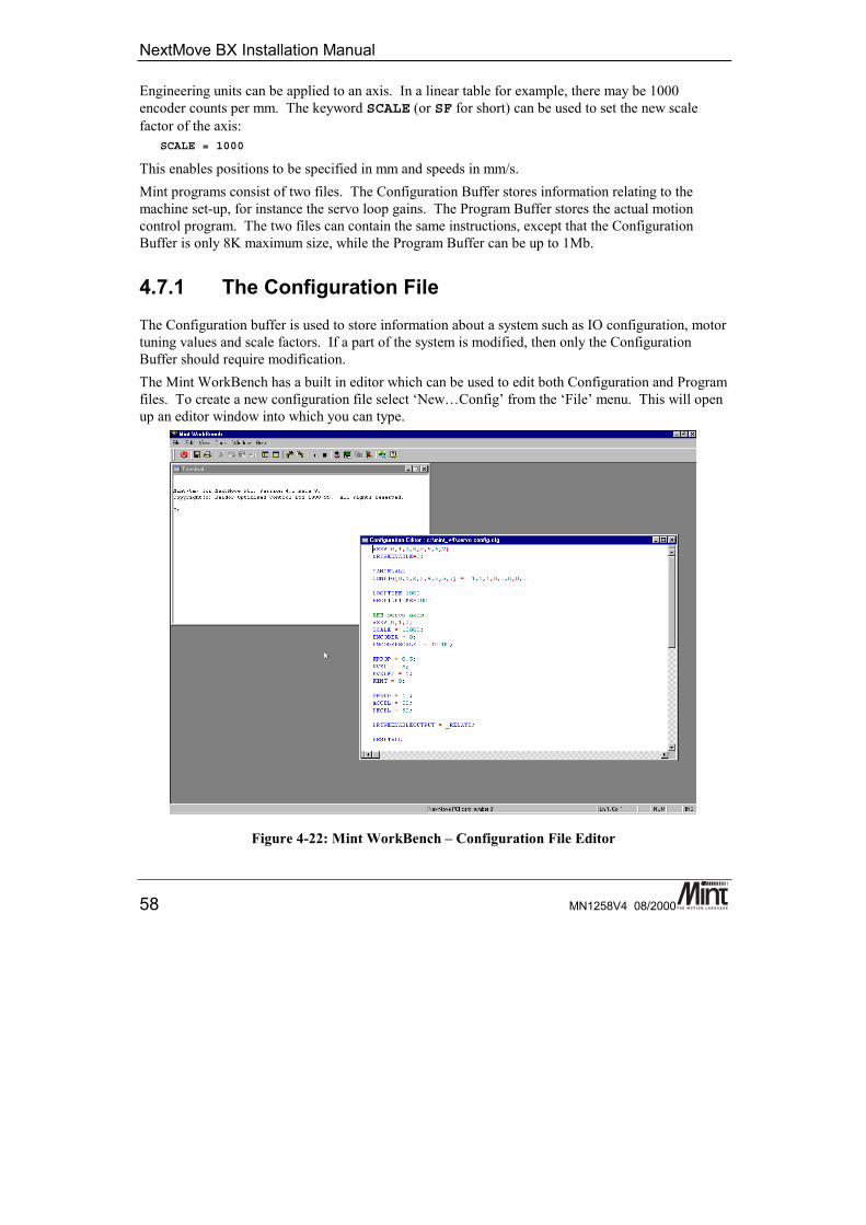
NextMove BX Installation Manual
58 MN1258V4 08/2000
Engineering units can be applied to an axis. In a linear table for example, there may be 1000encoder counts per mm. The keyword SCALE (or SF for short) can be used to set the new scalefactor of the axis:
SCALE = 1000
This enables positions to be specified in mm and speeds in mm/s.Mint programs consist of two files. The Configuration Buffer stores information relating to themachine set-up, for instance the servo loop gains. The Program Buffer stores the actual motioncontrol program. The two files can contain the same instructions, except that the ConfigurationBuffer is only 8K maximum size, while the Program Buffer can be up to 1Mb.
4.7.1 The Configuration FileThe Configuration buffer is used to store information about a system such as IO configuration, motortuning values and scale factors. If a part of the system is modified, then only the ConfigurationBuffer should require modification.The Mint WorkBench has a built in editor which can be used to edit both Configuration and Programfiles. To create a new configuration file select ‘New…Config’ from the ‘File’ menu. This will openup an editor window into which you can type.
Figure 4-22: Mint WorkBench – Configuration File Editor
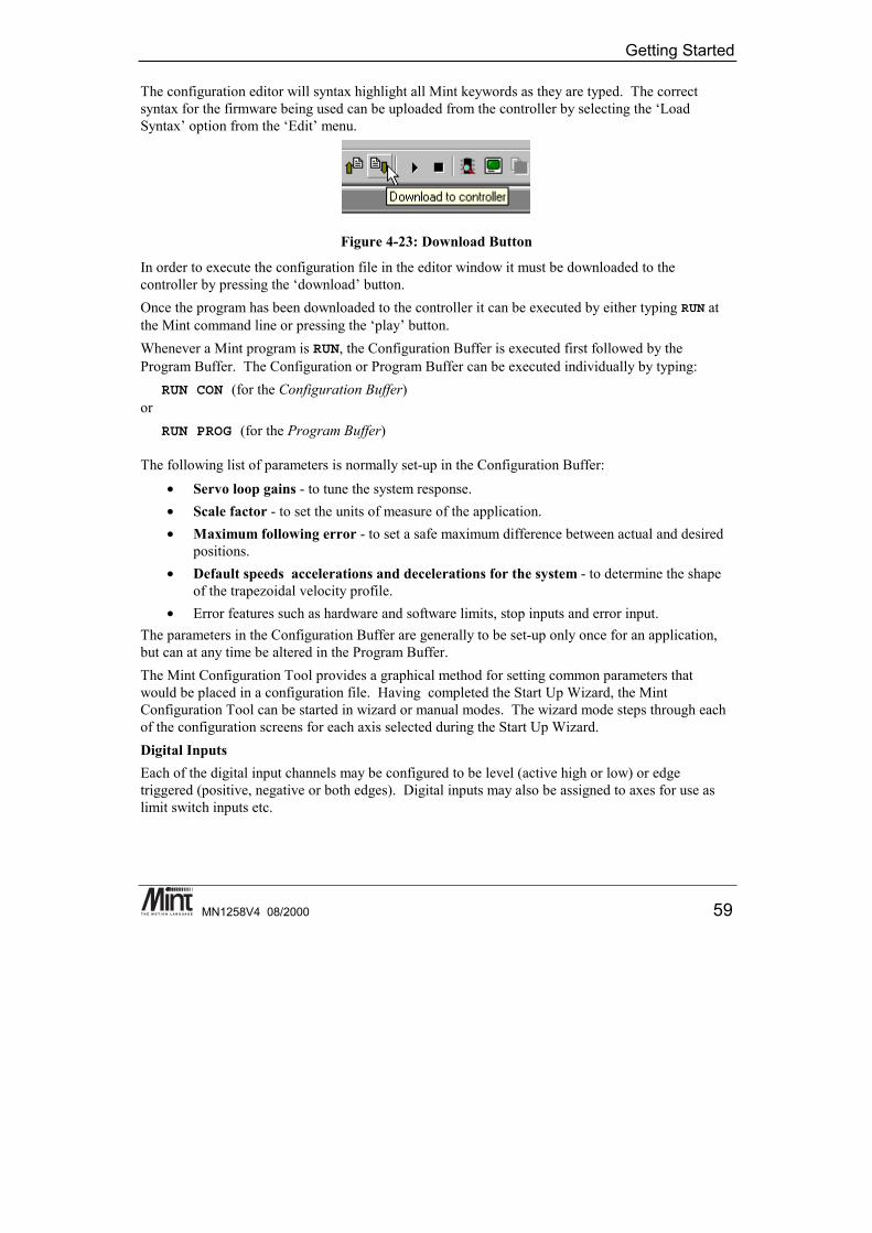
Getting Started
MN1258V4 08/2000 59
The configuration editor will syntax highlight all Mint keywords as they are typed. The correctsyntax for the firmware being used can be uploaded from the controller by selecting the ‘LoadSyntax’ option from the ‘Edit’ menu.
Figure 4-23: Download Button
In order to execute the configuration file in the editor window it must be downloaded to thecontroller by pressing the ‘download’ button.Once the program has been downloaded to the controller it can be executed by either typing RUN atthe Mint command line or pressing the ‘play’ button.Whenever a Mint program is RUN, the Configuration Buffer is executed first followed by theProgram Buffer. The Configuration or Program Buffer can be executed individually by typing:
RUN CON (for the Configuration Buffer)or
RUN PROG (for the Program Buffer)
The following list of parameters is normally set-up in the Configuration Buffer:• Servo loop gains - to tune the system response.• Scale factor - to set the units of measure of the application.• Maximum following error - to set a safe maximum difference between actual and desired
positions.• Default speeds accelerations and decelerations for the system - to determine the shape
of the trapezoidal velocity profile.• Error features such as hardware and software limits, stop inputs and error input.
The parameters in the Configuration Buffer are generally to be set-up only once for an application,but can at any time be altered in the Program Buffer.The Mint Configuration Tool provides a graphical method for setting common parameters thatwould be placed in a configuration file. Having completed the Start Up Wizard, the MintConfiguration Tool can be started in wizard or manual modes. The wizard mode steps through eachof the configuration screens for each axis selected during the Start Up Wizard.Digital InputsEach of the digital input channels may be configured to be level (active high or low) or edgetriggered (positive, negative or both edges). Digital inputs may also be assigned to axes for use aslimit switch inputs etc.
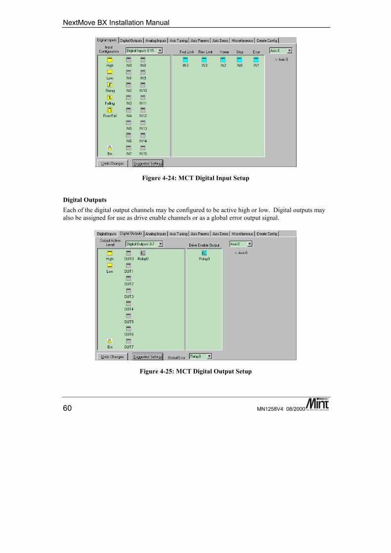
NextMove BX Installation Manual
60 MN1258V4 08/2000
Figure 4-24: MCT Digital Input Setup
Digital OutputsEach of the digital output channels may be configured to be active high or low. Digital outputs mayalso be assigned for use as drive enable channels or as a global error output signal.
Figure 4-25: MCT Digital Output Setup
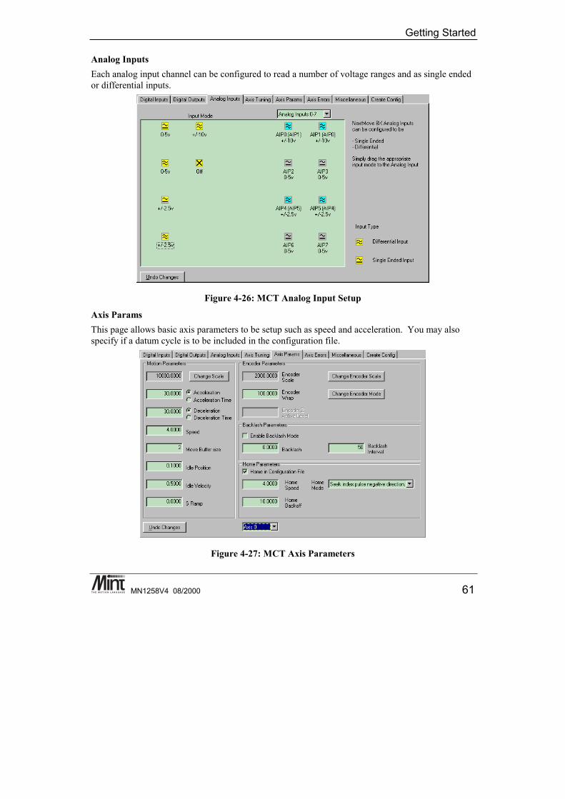
Getting Started
MN1258V4 08/2000 61
Analog InputsEach analog input channel can be configured to read a number of voltage ranges and as single endedor differential inputs.
Figure 4-26: MCT Analog Input Setup
Axis ParamsThis page allows basic axis parameters to be setup such as speed and acceleration. You may alsospecify if a datum cycle is to be included in the configuration file.
Figure 4-27: MCT Axis Parameters
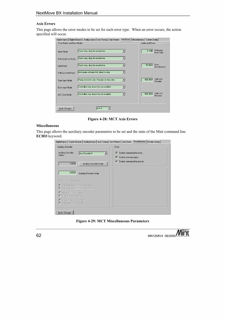
NextMove BX Installation Manual
62 MN1258V4 08/2000
Axis ErrorsThis page allows the error modes to be set for each error type. When an error occurs, the actionspecified will occur.
Figure 4-28: MCT Axis Errors
MiscellaneousThis page allows the auxiliary encoder parameters to be set and the state of the Mint command lineECHO keyword.
Figure 4-29: MCT Miscellaneous Parameters
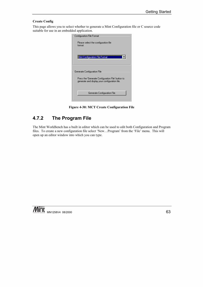
Getting Started
MN1258V4 08/2000 63
Create ConfigThis page allows you to select whether to generate a Mint Configuration file or C source codesuitable for use in an embedded application.
Figure 4-30: MCT Create Configuration File
4.7.2 The Program FileThe Mint WorkBench has a built in editor which can be used to edit both Configuration and Programfiles. To create a new configuration file select ‘New…Program’ from the ‘File’ menu. This willopen up an editor window into which you can type.
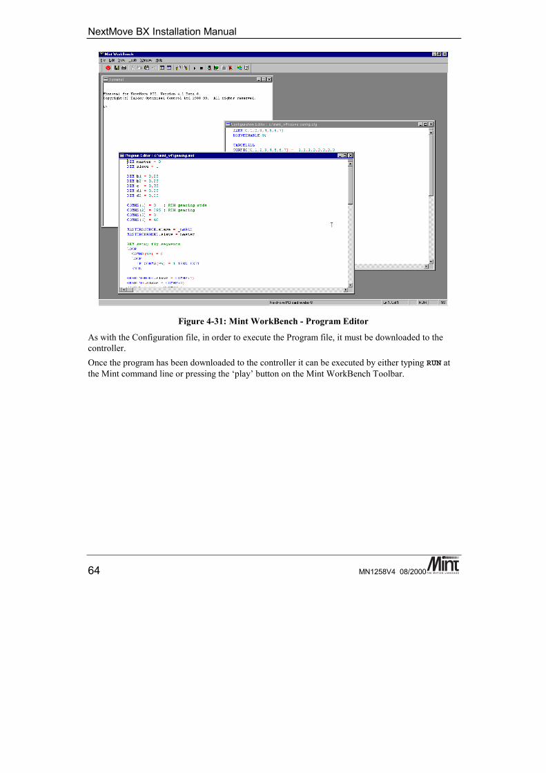
NextMove BX Installation Manual
64 MN1258V4 08/2000
Figure 4-31: Mint WorkBench - Program Editor
As with the Configuration file, in order to execute the Program file, it must be downloaded to thecontroller.Once the program has been downloaded to the controller it can be executed by either typing RUN atthe Mint command line or pressing the ‘play’ button on the Mint WorkBench Toolbar.
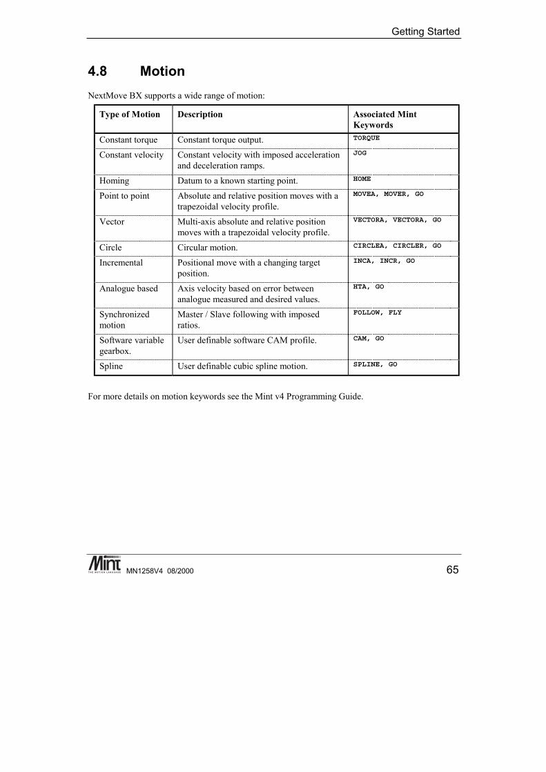
Getting Started
MN1258V4 08/2000 65
4.8 MotionNextMove BX supports a wide range of motion:
Type of Motion Description Associated MintKeywords
Constant torque Constant torque output. TORQUE
Constant velocity Constant velocity with imposed accelerationand deceleration ramps.
JOG
Homing Datum to a known starting point. HOME
Point to point Absolute and relative position moves with atrapezoidal velocity profile.
MOVEA, MOVER, GO
Vector Multi-axis absolute and relative positionmoves with a trapezoidal velocity profile.
VECTORA, VECTORA, GO
Circle Circular motion. CIRCLEA, CIRCLER, GO
Incremental Positional move with a changing targetposition.
INCA, INCR, GO
Analogue based Axis velocity based on error betweenanalogue measured and desired values.
HTA, GO
Synchronizedmotion
Master / Slave following with imposedratios.
FOLLOW, FLY
Software variablegearbox.
User definable software CAM profile. CAM, GO
Spline User definable cubic spline motion. SPLINE, GO
For more details on motion keywords see the Mint v4 Programming Guide.

NextMove BX Installation Manual
66 MN1258V4 08/2000

Options and Accessories
MN1258V4 08/2000 67
5. Options and Accessories
5This chapter describes the option and accessories for NextMove BX.
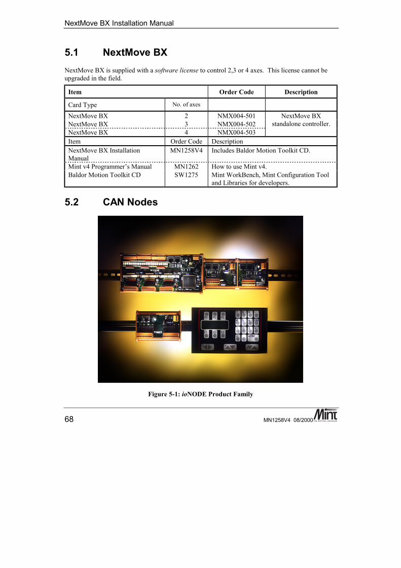
NextMove BX Installation Manual
68 MN1258V4 08/2000
5.1 NextMove BXNextMove BX is supplied with a software license to control 2,3 or 4 axes. This license cannot beupgraded in the field.
Item Order Code Description
Card Type No. of axes
NextMove BX 2 NMX004-501NextMove BX 3 NMX004-502NextMove BX 4 NMX004-503
NextMove BXstandalone controller.
Item Order Code DescriptionNextMove BX InstallationManual
MN1258V4 Includes Baldor Motion Toolkit CD.
Mint v4 Programmer’s Manual MN1262 How to use Mint v4.Baldor Motion Toolkit CD SW1275 Mint WorkBench, Mint Configuration Tool
and Libraries for developers.
5.2 CAN Nodes
Figure 5-1: ioNODE Product Family
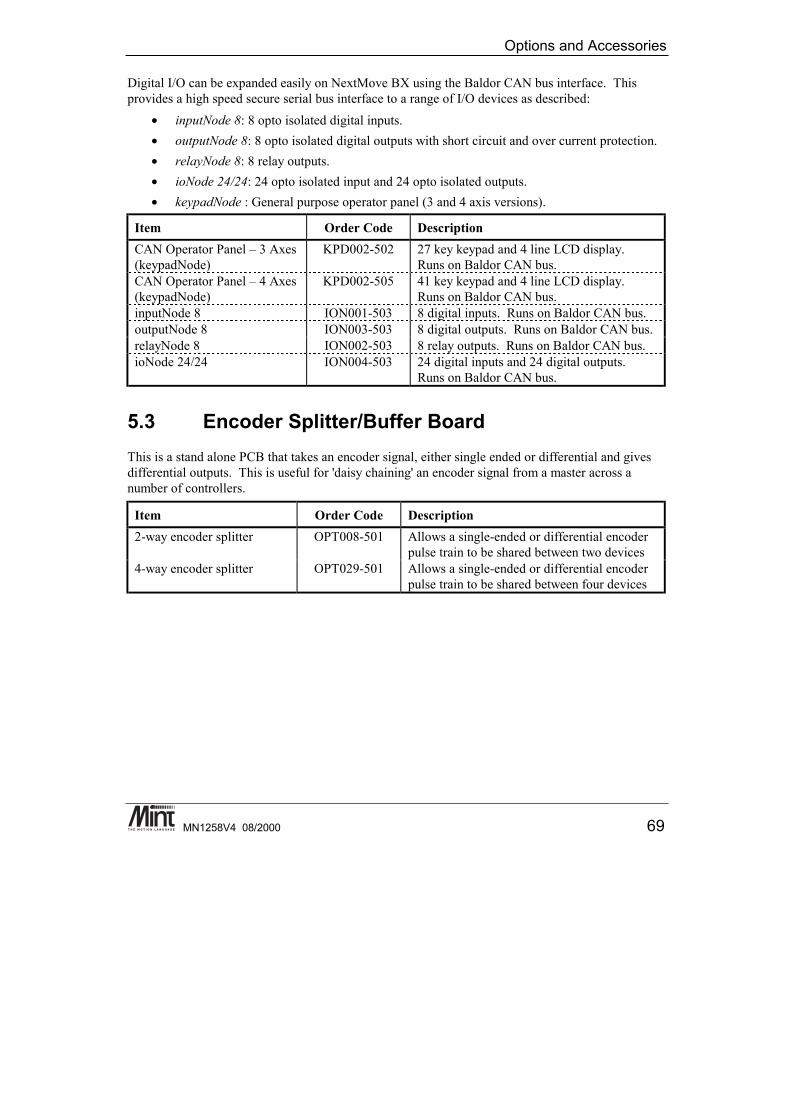
Options and Accessories
MN1258V4 08/2000 69
Digital I/O can be expanded easily on NextMove BX using the Baldor CAN bus interface. Thisprovides a high speed secure serial bus interface to a range of I/O devices as described:
• inputNode 8: 8 opto isolated digital inputs.• outputNode 8: 8 opto isolated digital outputs with short circuit and over current protection.• relayNode 8: 8 relay outputs.• ioNode 24/24: 24 opto isolated input and 24 opto isolated outputs.• keypadNode : General purpose operator panel (3 and 4 axis versions).
Item Order Code DescriptionCAN Operator Panel – 3 Axes(keypadNode)
KPD002-502 27 key keypad and 4 line LCD display.Runs on Baldor CAN bus.
CAN Operator Panel – 4 Axes(keypadNode)
KPD002-505 41 key keypad and 4 line LCD display.Runs on Baldor CAN bus.
inputNode 8 ION001-503 8 digital inputs. Runs on Baldor CAN bus.outputNode 8 ION003-503 8 digital outputs. Runs on Baldor CAN bus.relayNode 8 ION002-503 8 relay outputs. Runs on Baldor CAN bus.ioNode 24/24 ION004-503 24 digital inputs and 24 digital outputs.
Runs on Baldor CAN bus.
5.3 Encoder Splitter/Buffer BoardThis is a stand alone PCB that takes an encoder signal, either single ended or differential and givesdifferential outputs. This is useful for 'daisy chaining' an encoder signal from a master across anumber of controllers.
Item Order Code Description2-way encoder splitter OPT008-501 Allows a single-ended or differential encoder
pulse train to be shared between two devices4-way encoder splitter OPT029-501 Allows a single-ended or differential encoder
pulse train to be shared between four devices

NextMove BX Installation Manual
70 MN1258V4 08/2000

Options and Accessories
MN1258V4 08/2000 71
6. Specifications and Product Data
6This chapter provides a product summary and describes the basis for CEmarking and describes how to avoid common EMC problems when usingNextMove BX.

NextMove BX Installation Manual
72 MN1258V4 08/2000
6.1 Machine Control I/OUser Digital
Inputs:• 16 input lines.• PNP or NPN opto-isolated relative to common.• 12 to 24V ±20% on, 3V max off.• Software programmable as limit, home, stop or error inputs for any axis.
User DigitalOutputs:
• 8 digital outputs driven through a Darlington array.• Software programmable as drive enable output for any axis.• 50mA continuous source on all channels.• Max. 350mA on any channel 750mA total @ 25°C.
FastInterrupt:
• One fast plus three ‘slow’ fast inputs per controller.• Latches position of programmed axes within 30 microseconds / 1 millisecond
on a falling edge.Relay
Output:• Voltage free change over relay rated at 500mA @ 24V dc.• Contact sensitivity 10µA @ 10mV DC• 1 output per controller, software programmable.• Fail safe operation: relay de-energized on loss of power.• Software programmable to de-energize on an error.
AnalogInputs:
• 8 independent analog channels. Configurable as 8 single ended or 4differential pairs.
• 12 bit resolution.• Software selectable for ±10V (differential) or 0-5/±2.5V single ended
operation.Analog
Outputs:• 1 output per axis for motor command signal (software configurable).• ±10V output (±0.1%).• 14 bit resolution (1.21mV per bit).
EncoderInputs:
• Encoder input per axis for positional feedback via incremental encoder.• Operates with differential (TTL or RS422) output type.• Accepts three channel incremental encoders (A, B and Z). A and B channels
are quadrature decoded.• Minimum requirement: Channel A and B .• Maximum encoder frequency: 7.3MHz quadrature count.

Options and Accessories
MN1258V4 08/2000 73
6.2 Miscellaneous and Mechanical SpecificationPower Input • +24V DC (±20%) @ 700mA.
• User Power: +12V to 24V ±20% at 850mA.InternalBattery
• 3.6V 3 cell nickel metal hydride (NiMH) with 280mAh capacity & 5 year life.• Non-volatile RAM contents retained for 12 months when fully charged.
Dimensions • 280mm (316mm including flanges) x 236mm x 59mm.• 11 in (12.45 including flanges) x 9.3 in x 2.32 in.
Weight • Approximately 1.86kg / 4.1lbOperating
Temperature• 0 - 40°C / 32° - 104°F Ambient.
Humidity • 10% to 90% non condensing at sea level to 2000m/6560ft.
Bookcase Format Motion Controller Overall Dimensions
NextMove
Baldor
DSP multi-axisservo controller
315
mm
12.4
"
302m
m11
.9"
59 mm2.3"
40mm1.5"
236mm9.3"
Figure 6-1: NextMove BX Bookcase Format Overall Dimensions
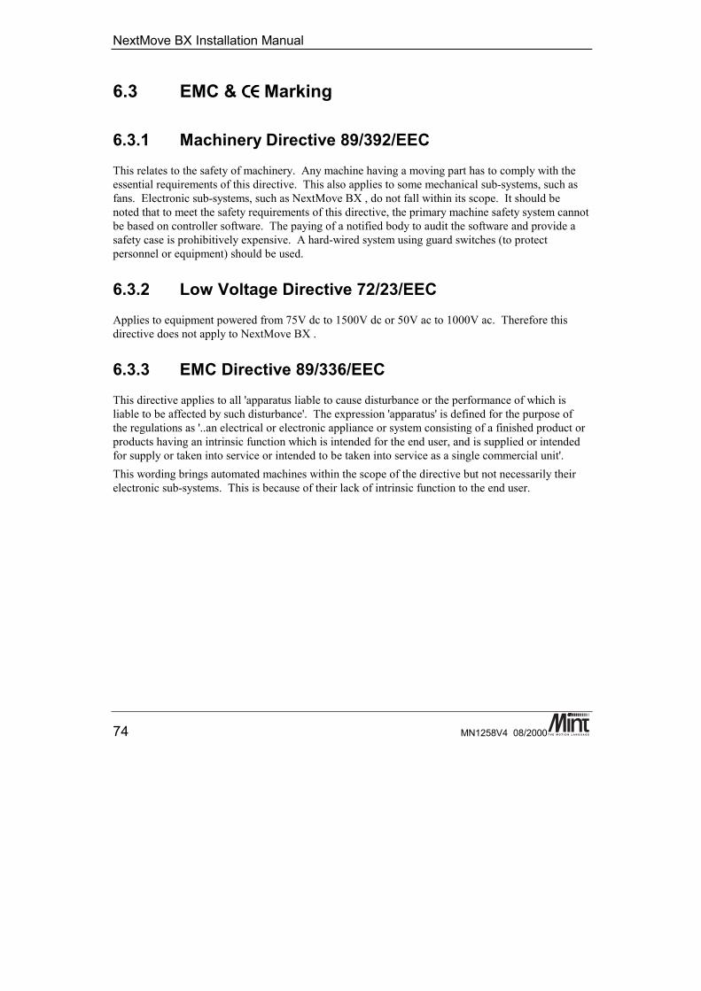
NextMove BX Installation Manual
74 MN1258V4 08/2000
6.3 EMC & CECECECE Marking
6.3.1 Machinery Directive 89/392/EECThis relates to the safety of machinery. Any machine having a moving part has to comply with theessential requirements of this directive. This also applies to some mechanical sub-systems, such asfans. Electronic sub-systems, such as NextMove BX , do not fall within its scope. It should benoted that to meet the safety requirements of this directive, the primary machine safety system cannotbe based on controller software. The paying of a notified body to audit the software and provide asafety case is prohibitively expensive. A hard-wired system using guard switches (to protectpersonnel or equipment) should be used.
6.3.2 Low Voltage Directive 72/23/EECApplies to equipment powered from 75V dc to 1500V dc or 50V ac to 1000V ac. Therefore thisdirective does not apply to NextMove BX .
6.3.3 EMC Directive 89/336/EECThis directive applies to all 'apparatus liable to cause disturbance or the performance of which isliable to be affected by such disturbance'. The expression 'apparatus' is defined for the purpose ofthe regulations as '..an electrical or electronic appliance or system consisting of a finished product orproducts having an intrinsic function which is intended for the end user, and is supplied or intendedfor supply or taken into service or intended to be taken into service as a single commercial unit'.This wording brings automated machines within the scope of the directive but not necessarily theirelectronic sub-systems. This is because of their lack of intrinsic function to the end user.
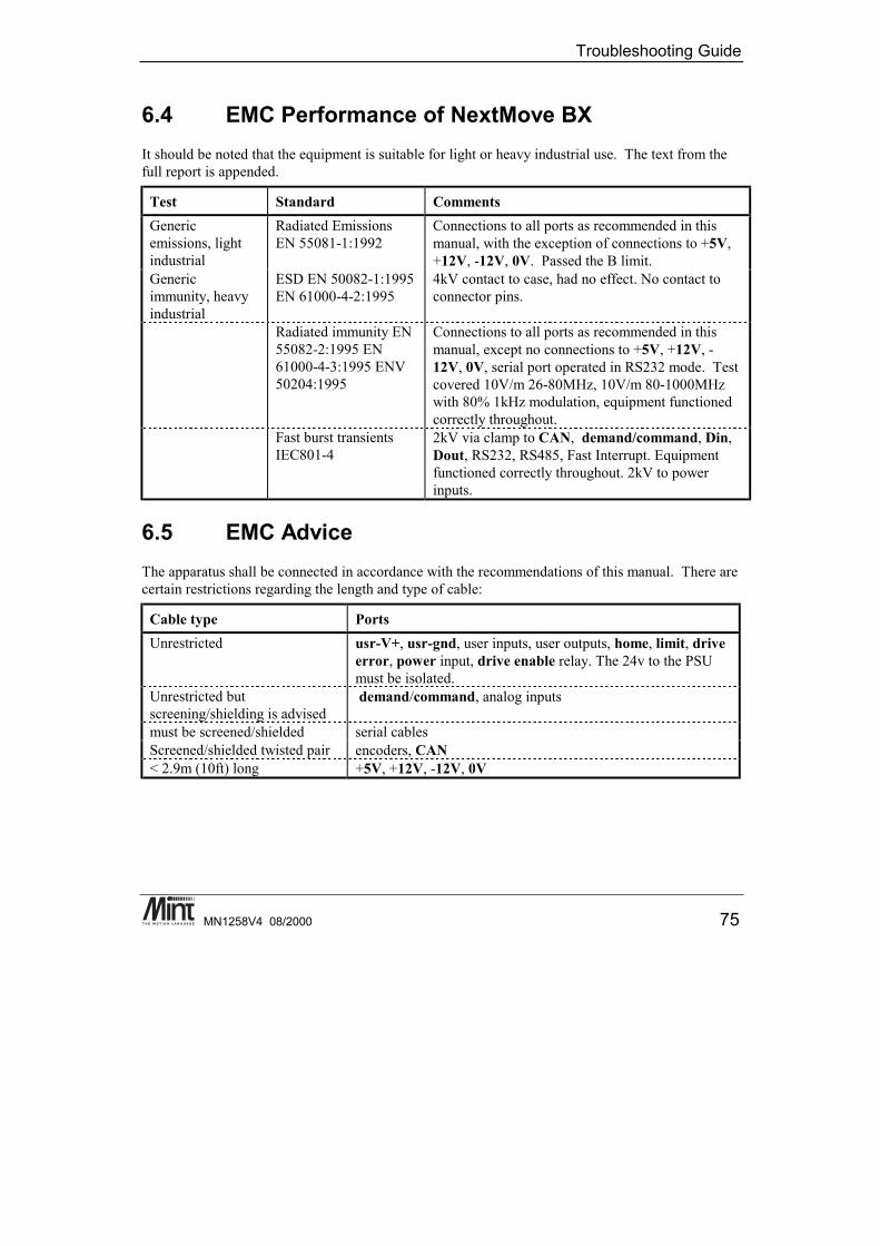
Troubleshooting Guide
MN1258V4 08/2000 75
6.4 EMC Performance of NextMove BXIt should be noted that the equipment is suitable for light or heavy industrial use. The text from thefull report is appended.
Test Standard CommentsGenericemissions, lightindustrial
Radiated EmissionsEN 55081-1:1992
Connections to all ports as recommended in thismanual, with the exception of connections to +5V,+12V, -12V, 0V. Passed the B limit.
Genericimmunity, heavyindustrial
ESD EN 50082-1:1995EN 61000-4-2:1995
4kV contact to case, had no effect. No contact toconnector pins.
Radiated immunity EN55082-2:1995 EN61000-4-3:1995 ENV50204:1995
Connections to all ports as recommended in thismanual, except no connections to +5V, +12V, -12V, 0V, serial port operated in RS232 mode. Testcovered 10V/m 26-80MHz, 10V/m 80-1000MHzwith 80% 1kHz modulation, equipment functionedcorrectly throughout.
Fast burst transientsIEC801-4
2kV via clamp to CAN, demand/command, Din,Dout, RS232, RS485, Fast Interrupt. Equipmentfunctioned correctly throughout. 2kV to powerinputs.
6.5 EMC AdviceThe apparatus shall be connected in accordance with the recommendations of this manual. There arecertain restrictions regarding the length and type of cable:
Cable type PortsUnrestricted usr-V+, usr-gnd, user inputs, user outputs, home, limit, drive
error, power input, drive enable relay. The 24v to the PSUmust be isolated.
Unrestricted butscreening/shielding is advised
demand/command, analog inputs
must be screened/shielded serial cablesScreened/shielded twisted pair encoders, CAN< 2.9m (10ft) long +5V, +12V, -12V, 0V

NextMove BX Installation Manual
76 MN1258V4 08/2000

Troubleshooting Guide
MN1258V4 08/2000 77
7. Troubleshooting Guide
7This chapter covers common problems found when using the NextMove BXcontroller.

NextMove BX Installation Manual
78 MN1258V4 08/2000
7.1 Trouble Shooting Guide
Symptom CheckCannot detect NextMove BX inthe Mint WorkBench of the MintConfiguration Tool.
• The NextMove BX must be running a version of Mint v4to be detected. If upgrading from Mint v3 firmware thenthe select ‘controller with no firmware’ from the MintWorkBench and ‘update firmware’ to Mint v4.
• Check that the correct serial port is in use and that thelead is plugged in at both ends.
• Check wiring for the RS232 lead.Status display blank andcontroller not functioning
• Check the power supply (24V dc) is connected andswitched on.
Cannot communicate withcontroller. (cannot get P> or C>prompt by pressing return).
• Check that there is not a program already running on thecontroller (type [Ctrl] + [E] to abort the program).
• Check that the terminal mode. Select ‘Tools’ and‘Terminal Mode’ from the Mint WorkBench.
Controller appears to be powered-up and working but will not causemotors to turn over.
• Check that the connections between motor and controllerare correct. Use the Mint Configuration Tool to performthe basic system wiring tests described in section 4.4.
• Ensure that the amplifier is enabled and working when thecontroller is not in error. (When the controller is firstpowered up the amplifiers should be disabled if there isno program running (there is often an LED on the front ofthe amplifier to indicate status).
• Check that the Configuration file is loaded into controllerand has been RUN, or that the servo loop gains arecorrectly set-up. (Check the Gains window or typePRINT KP to verify that the controller proportional gainKP is not zero and refer to servo-system set-up).
Motor runs off uncontrollablywhen controller is switched on.
• Check that the encoders are connected to controller, havepower through encoder V+ and are functioning correctly.(Use a dual trace oscilloscope to display both channels ofthe encoder and/or the complements simultaneously).
• Check that the amplifiers are connected correctly to thecontroller and that with zero demand there is 0V at theamplifier demand input.
• Verify that the controller and amplifier are correctlygrounded to a common earth point.

Troubleshooting Guide
MN1258V4 08/2000 79
Motor runs off uncontrollablywhen controller is switched onand servo loop gains are appliedor when a move is set in progress.Motor then stops after a shorttime.
• Check that encoder 0 and demand 0 are connected to thesame axes of motion; repeat for axis 1 and 2. Checkamplifier connection is correct with respect to polarity ofamplifier demand.
• Check that for a positive command signal, a positiveincrease in axis position is seen. The DACMODE keywordcan be used to reverse DAC output polarity.
• Check that the maximum following error is set to areasonable value. For setting up purposes, following errordetection may be disabled by setting FOLERRORMODE =0.
Motor is under control, butvibrates or overshoots during amove.
• Servo loop gains may be set too high. (Go through theservo system set-up procedure to establish correct gains.)
Motor is under control, but whenmoved to a position and then backto the start it does not return to thesame position.
• Check that all encoder channels are clear signals and thatthey are correctly wired to the controller. (Use a dualtrace oscilloscope to display channels A and B of theencoder at the controller Breakout Unit. Verify that whenthe motor turns, the two square wave signals are 90degrees out of phase. Also check the complement signals.)
• Check that the encoder signals are free from electricalnoise. (Use the oscilloscope as above).
• Ensure that the encoder leads uses screened twisted paircable and that the screen is attached to the screenconnection on the encoder plug at the controller endonly.)
• Verify that the controller and amplifier are correctlygrounded to a common earth point.

NextMove BX Installation Manual
80 MN1258V4 08/2000
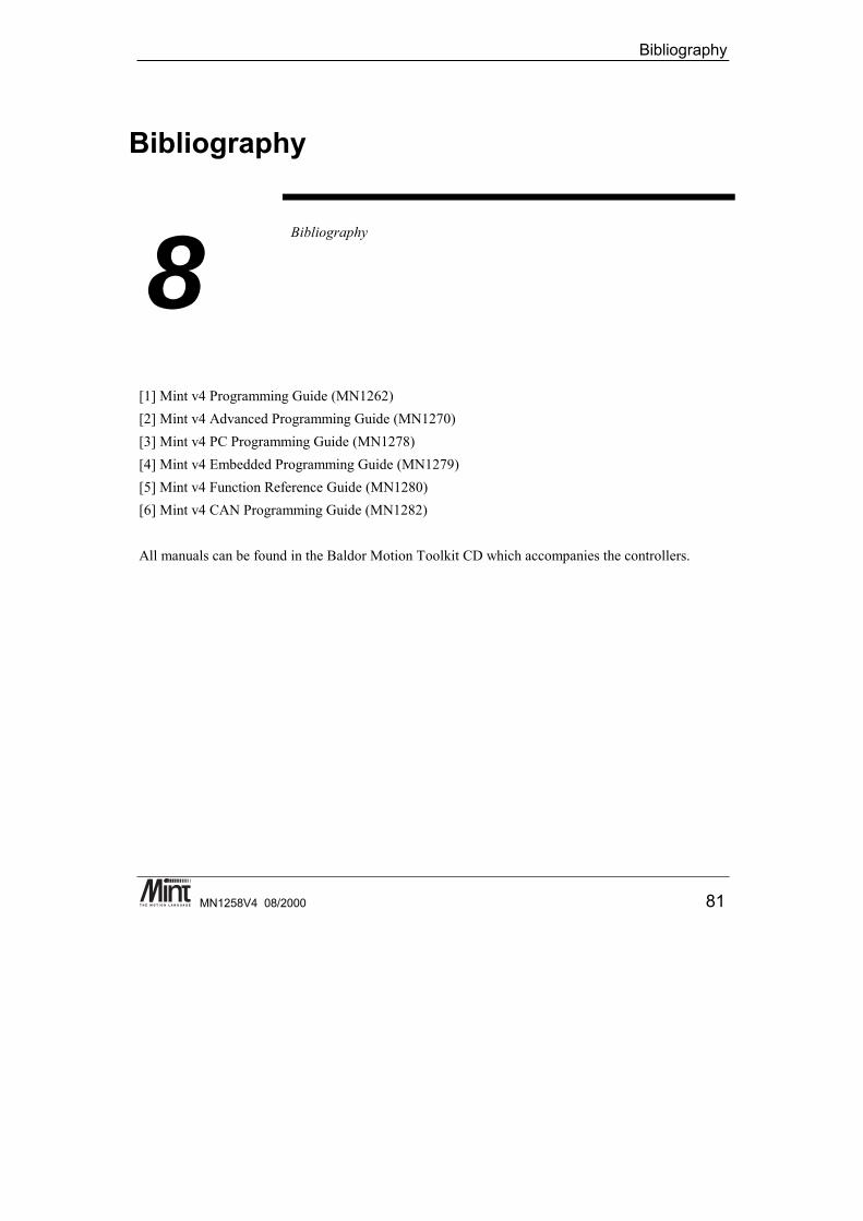
Bibliography
MN1258V4 08/2000 81
8. Bibliography
8Bibliography
[1] Mint v4 Programming Guide (MN1262)[2] Mint v4 Advanced Programming Guide (MN1270)[3] Mint v4 PC Programming Guide (MN1278)[4] Mint v4 Embedded Programming Guide (MN1279)[5] Mint v4 Function Reference Guide (MN1280)[6] Mint v4 CAN Programming Guide (MN1282)
All manuals can be found in the Baldor Motion Toolkit CD which accompanies the controllers.

NextMove BX Installation Manual
82 MN1258V4 08/2000