next generation wireless requirements for automotive
TRANSCRIPT

Standards
Certification
Education & Training
Publishing
Conferences & Exhibits
Next Generation Wireless Requirements for Automotive ManufacturingUnique Requirements for Discrete Parts Manufacturing

2
Presenter
• Mike Read– Senior Technical Specialist – IT - Ford Motor Company– Former Controls Engineer and Instrumentation Engineer– Controls/IT Liaison– Focus area: Programmable Device Interface and Networking– Member: USCAR Programmable Controls Committee

3
What is USCAR?
The United States Council for Automotive Research (USCAR) is the umbrella organization for collaborative research among Chrysler LLC, Ford Motor Company and General Motors Corporation. Founded in 1992, the goal of USCAR is to further strengthen the technology base of the domestic auto industry through cooperative research and development.
4
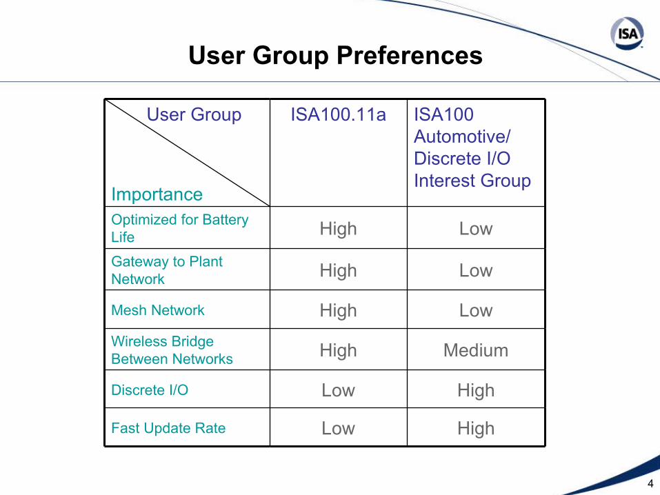
MediumHighWireless Bridge Between Networks
HighLowFast Update Rate
HighLowDiscrete I/O
LowHighMesh Network
LowHighGateway to Plant Network
LowHighOptimized for Battery Life
ISA100 Automotive/ Discrete I/O Interest Group
ISA100.11a User Group
Importance
User Group Preferences

5
Why Wireless?
• Wireless I/O is desired for equipment where wiring is either high maintenance, not physically possible or cost prohibitive
• Wireless is NOT intended to be the replacement for all currently wired networks

6
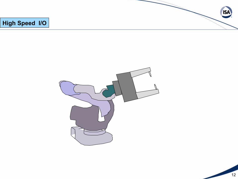
High Speed I/O Typical examples
• Robot end effector • Wiring is routed through the robot
and is high maintenance due to continuous cable flex and tight radius joints.
High Speed I/O

7
High Speed I/O

8
High Speed I/O

9
High Speed I/O

10
High Speed I/O

11
High Speed I/O
12
High Speed I/O

13
High Speed I/O
14
Additional High Speed I/O Typical examples
• Places where hard wiring is not an option and bus communications are high maintenance • Carriers on electrified monorail systems• Track mounted and rotary equipment
• Wireless Emergency Stop for wireless teach pendants
High Speed I/O
15
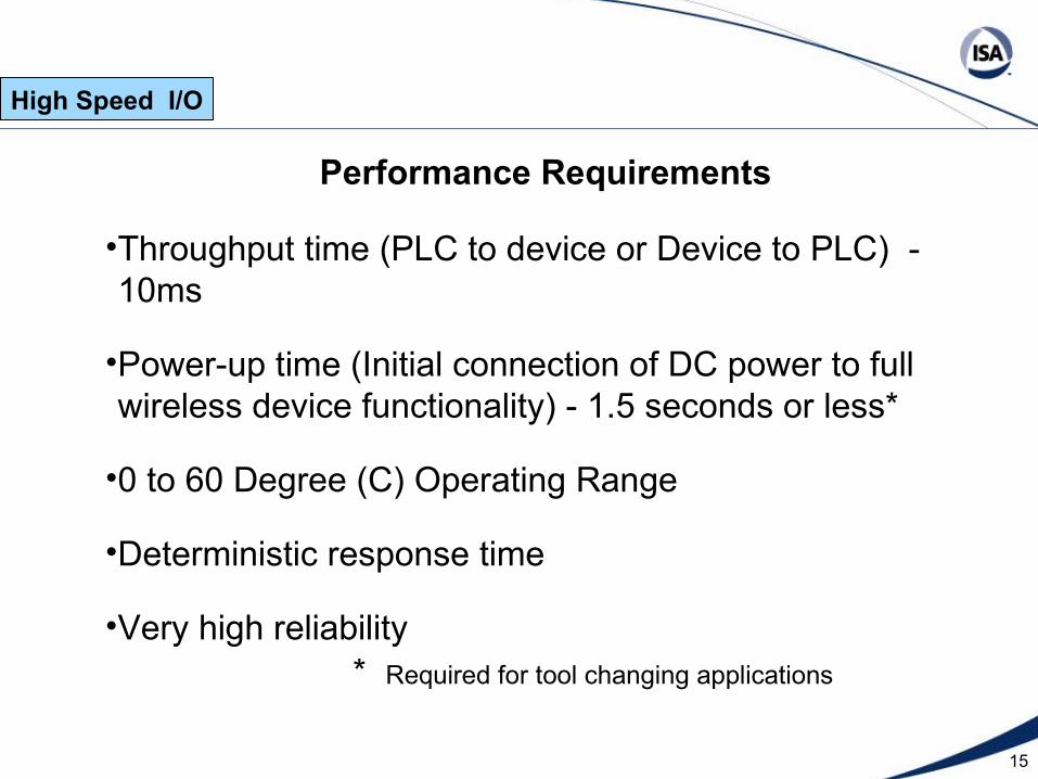
Performance Requirements
•Throughput time (PLC to device or Device to PLC) - 10ms
•Power-up time (Initial connection of DC power to full wireless device functionality) - 1.5 seconds or less*
•0 to 60 Degree (C) Operating Range
•Deterministic response time
•Very high reliability
High Speed I/O
* Required for tool changing applications

16
Performance Requirements
•High density - approximately 50 instances of devices with 16 I/O points each within a 10M radius
•High EMF/RFI tolerance - Capable of operation in close proximity to welding and other RF devices
•Must not interfere with existing 802.11 b/g/a/n infrastructure
High Speed I/O

17
Form Factor
• Many unique switches placed in difficult locations
• Tightly clustered
• 8-16 I/O points per group
• Independently powered outputs
High Speed I/O

18
Device Connection
•Discrete Wired•8-16 I/O devices independently wired per RF device
OR
•DeviceNet Wired•8-16 I/O DeviceNet devices per RF device
High Speed I/O

19
Power Supply
•24 Volt DC power is locally available for field power in most applications
•Daily battery change is acceptable if required for wireless Emergency stop applications.
High Speed I/O

20
PLC Interface
•EtherNet/IP•DeviceNet – alternative
Range
•Wireless I/O to PLC typically 10M or less
High Speed I/O

21
Secure Wireless Controls - Ethernet Applications
• Mobile PLC applications• AGV systems• Track mounted systems• Rotary test stand applications
Medium Speed I/O

22
Secure Wireless Controls Ethernet Requirements
• Isolated, secure controls networks• Connection to a secure wireless access point • Access point must manage security, not the PLC
Medium Speed I/O

23
Performance Requirements
• 2Mbps data rate • Must not interfere with existing
802.11 b/g/a/n infrastructure• Low Power 802.11A UNI 1 and UNI 2
band preferred. Adjustable power required for distance limiting.
Medium Speed I/O
24
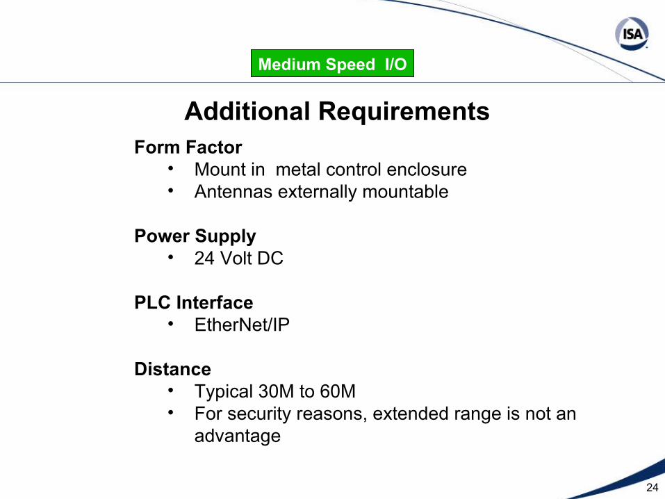
Form Factor • Mount in metal control enclosure• Antennas externally mountable
Power Supply • 24 Volt DC
PLC Interface • EtherNet/IP
Distance • Typical 30M to 60M • For security reasons, extended range is not an
advantage
Medium Speed I/O
Additional Requirements

25
Low Speed Applications
• Useful for applications that are cost prohibitive to wire back to a central location
• Remote temperature sensors and setpoints for energy management applications
• Machine mounted vibration signature devices
• Utility meters for power, gas, steam, compressed air, etc.
Low Speed I/O
26
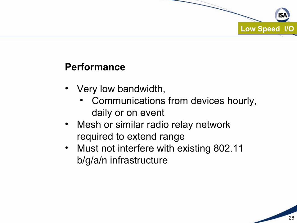
Performance
• Very low bandwidth, • Communications from devices hourly,
daily or on event• Mesh or similar radio relay network
required to extend range• Must not interfere with existing 802.11
b/g/a/n infrastructure
Low Speed I/O

27
Form Factor
• Typical installations are in a metal control enclosure• Externally mountable antenna
Low Speed I/O
28
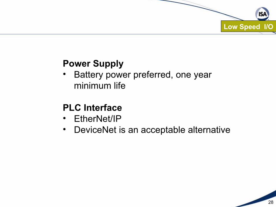
Power Supply• Battery power preferred, one year
minimum life
PLC Interface • EtherNet/IP• DeviceNet is an acceptable alternative
Low Speed I/O
29
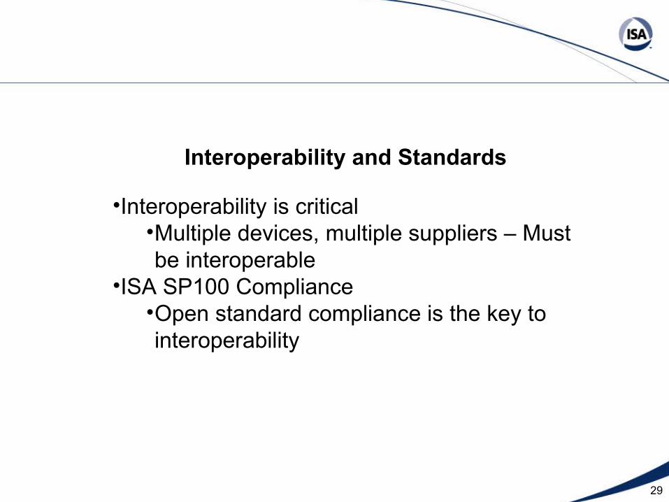
Interoperability and Standards
•Interoperability is critical•Multiple devices, multiple suppliers – Must be interoperable
•ISA SP100 Compliance•Open standard compliance is the key to interoperability

30
Requirements for a safe and secure wireless controls network:
• Prevent on-line programming from remote locations
• Prevent unauthorized access to programmable controls devices
• Prevent malicious tampering • Prevent inadvertent tampering

31
Network Segmentation
Isolated network segments serve several important functions:
• Limit the group-to-group exposure
• Limit the ability to make remote changes from beyond safe working distance from the equipment

32
Component “B” Machining Area
Component “A” Machining Area
ComponentAssembly Area
Isolated Segment 3
Isolated Segment 1
Isolated Segment 2
Flow
Flow
Flow
PLANT LAYOUT
Component “B” Machining Area
Component “A” Machining Area
ComponentAssembly Area
Isolated Segment 3
Isolated Segment 1
Isolated Segment 2
FlowFlow
FlowFlow
FlowFlow
PLANT LAYOUT

33
Machine Tool Machine Tool
Machine Tool Machine Tool
Machine Tool Machine Tool
Machine Tool Machine ToolControls Wireless
Access PointLine of Sight 3
OA Wireless Access Point
Controls Wireless Access Point
Line of Sight 2
Controls Wireless Access Point
Line of Sight 4
Controls Wireless Access Point
Line of Sight 1
OA Wireless Access Point Desired Wireless Office Environment

34
Machine Tool Machine Tool
Machine Tool Machine Tool
Machine Tool Machine Tool
Machine Tool Machine ToolControls Wireless
Access PointLine of Sight 3
OA Wireless Access Point
Controls Wireless Access Point
Line of Sight 2
Controls Wireless Access Point
Line of Sight 4
Controls Wireless Access Point
Line of Sight 1
OA Wireless Access Point Desired Wireless Controls Environment
