newscope-5 operating manual - ipagesimmconnlabscom.ipage.com/tech/newscope-5_om.pdf · 1...
TRANSCRIPT

©2013-2014 SIMMCONN Labs, LLC All rights reserved
March 29, 2015
NewScope-5 Operating Manual For Kits with Main Board Serial Number NS51000 and above

NewScope-5 Operating Manual
1 Introduction .......................................................................................................................................... 3
2 Installation ............................................................................................................................................ 4
2.1 Initial Inspection ............................................................................................................................ 4
2.2 Installation of the NewScope-5 Kit ............................................................................................... 5
2.2.1 Read before installation ........................................................................................................ 5
2.2.2 Prepare the unit for installation ............................................................................................ 6
2.2.3 Installation on a 3577A/B or 3562A/3563A unit ................................................................... 6
2.2.4 Installation on a 4145A/B unit .............................................................................................. 9
2.2.5 Installation on an 8756A unit .............................................................................................. 13
2.2.6 Finishing installation ........................................................................................................... 16
3 Operations .......................................................................................................................................... 17
3.1 Intensity control .......................................................................................................................... 17
3.2 Focus control ............................................................................................................................... 17
3.3 LEDs ............................................................................................................................................. 18
3.4 Jumpers ....................................................................................................................................... 18
3.5 Other Onboard Connectors ........................................................................................................ 19

1 Introduction The NewScope-5 Color LCD replacement Kit is designed to replace the HP® 1345A monochrome CRT displays used in 3577A/B, 3562A, 3563A, 8756A, 4145A/B and other test equipment1. The Kit supports 5.7” or 6.5” TFT color LCD with VGA (640 x 480) resolution. The key features of the Kit include:
• Bitmap font with hand-optimized glyphs gives better clarity over the original vector font when rendered on a raster LCD panel
• Display items are differentiated by colors, similar to later models of the same test equipment family
• Four display schemes selectable by the Focus adjustment • The 1345A vector memory option (option 704) can be enabled by a jumper • Analog VGA output option to drive external VGA monitor (available on 3562A, 3563A, 8756A
and 4145A) • The LCD backlight is powered from the regulated +15V that was used for the 1345A display in
the system
Figure 1 NewScope-5 5.7” SVGA Kit shown with default (NewScope) display scheme
1 NewScope-5 is not compatible with units that use the analog X-Y-Z input of the 1345A display, such as 8980A and 8981A/B Vector Modulation Analyzers

2 Installation
2.1 Initial Inspection The kits for different units may have different contents. Please check and make sure the kit you ordered match with the unit you are installing the kit into. Verify that all parts listed in the table corresponding to your kit are present.
Table 1 NewScope-5 Kit Content for 3577A/B, 3562A and 3563A units
Item Qty Reference Description Note 1 1 NewScope-5 Main board, NewScope LCD Kit 2 2 1 LVDS_ADP Display Board, NewScope LCD Kit 1 3 1 18-0002-001 FFC cable, 33 conductor, 0.5mm pitch, 50mm 1 4 1 18-0001-006 Display Link Cable, LVDS, 20 Conductor, Shielded 1 5 1 18-0001-010 LCD Back Light Cable, 5 Conductor 1 6 1 19-0001-001 Main board bracket 2 7 1 LCD Panel, 5.7 Inch 1 8 1 19-0001-002 LCD Panel Bracket with PCB mounting posts 1 9 1 19-0001-002A LCD Panel Bracket w/o PCB mounting posts 1 10 4 #2 x ¼” Pan-head screw, self-tapping 1 11 4 M3 x 6 Pan-head Philips screw 2 12 2 M3 x 4 Pan-head Philips screw 1 13 1 Foam strip for 5.7” LCD panel Note: 1. Shipped pre-assembled as LCD panel assembly. 2. Shipped pre-assembled as Main board assembly.
Table 2 NewScope-5 Kit Content for 4145A/B
Item Qty Reference Description Note 1 1 NewScope-5 Main board, NewScope LCD Kit 2 2 2 18-0001-012 Control Pot Cable Extender, 3 Conductor 3 1 18-0001-006 Display Link Cable, LVDS, 20 Conductor, Shielded 1 4 1 18-0001-007 LCD Back Light Cable, 5 Conductor 1, for AUO panels 1 18-0001-014 LCD Back Light Cable, 2 Conductor 1, for KOE panels 5 1 19-0001-001 Main board bracket 2 6 1 LCD Panel, 6.5 Inch 1 7 1 19-0001-003 LCD Panel Bracket for 4145A/B 1 8 4 M3 x 4 Flat-head Philips screw 9 4 M2 x 3 Pan-head T-6 screw 1 10 5 M3 x 6 Pan-head Philips screw 2 11 3 6-32 x ¼” Flat-head Philips screw

Note: 1. Shipped pre-assembled as LCD panel assembly. 2. Shipped pre-assembled as Main board assembly.
Table 3 NewScope-5 Kit Content for 8756A
Item Qty Reference Description Note 1 1 NewScope-5 Main board, NewScope LCD Kit 2 3 1 18-0001-006 Display Link Cable, LVDS, 20 Conductor, Shielded 1 4 1 18-0001-007 LCD Back Light Cable, 5 Conductor 1, for AUO panels 1 18-0001-014 LCD Back Light Cable, 2 Conductor 1, for KOE panels 5 1 18-0001-012 Power Extension Cable, 6 conductor 6 1 19-0001-001 Main board bracket 2 7 1 LCD Panel, 6.5 Inch 1 8 1 19-0001-003A LCD Panel Bracket for 8756A 1 9 4 M3 x 4 Flat-head Philips screw 10 4 M2 x 3 Pan-head T-6 screw 1 11 3 M3 x 6 Pan-head Philips screw 2 12 2 M3 x 4 Pan-head Philips screw 2 Note: 1. Shipped pre-assembled as LCD panel assembly. 2. Shipped pre-assembled as Main board assembly.
2.2 Installation of the NewScope-5 Kit Installation should be performed by a qualified technical person who is familiar with the host test equipment.
The Kit installation time is approximately 30 minutes. Please refer to test equipment service manuals for location of the assemblies.
Caution: CRT could have up to 9 KV potential on the anode. Use proper precautions when handling CRT Assembly.
Note: Dispose of display within your state’s hazardous materials guidelines for CRT’s and electronics.
2.2.1 Read before installation Please treat the parts and assemblies with care during installation. Take the following guidelines when installing the kit:
1) Do not use power tools to fasten screws. Use a manual screwdriver so that you can see and feel if something is not well aligned. If you meet considerable resistance when fastening a screw, back off and try again.
2) The connectors are fragile. If you meet resistance when trying to make a connection, wiggle the connector gently left and right, let it find its way and then gradually plug in. Do the same when disconnecting a cable.

3) Do not force anything into position. If something doesn't seem to fit, give it a little wiggle room and it will likely correct itself.
4) Before you try to modify some part that doesn’t seem to fit, take a short break and read the manual one more time. Chances are some steps in the manual may not be very clear or well understood. Ask questions and we'll get back to you as soon as we can.
2.2.2 Prepare the unit for installation Disconnect AC power cord. Remove the top cover from the equipment. Follow the manufacturer’s ESD precaution guidelines in the unit’s service manual.
2.2.3 Installation on a 3577A/B or 3562A/3563A unit
2.2.3.1 Remove the CRT display unit Refer to the test equipment service manuals for procedures to remove the display unit:
Remove the sheet metal cover of the display unit.
Remove the adhesive trim strip from left side of instrument front frame. Remove two M3.5 flat-head screws located under the trim strip securing the front trim bezel. Save the screws for later installation. Remove the plastic trim strip on top of the unit by inserting a small flat screwdriver into the slot and lifting upwards. Remove two M3.5 flat-head screws located under trim strip securing the front trim bezel. Save the screws for later installation.
Remove the display trim pot assembly from the rear subpanel.

Remove 2 screws on the rear side of the display unit. On the 3577A/B, there is one additional screw at the rear bottom of the display unit that needs to be removed.
Slowly remove the display unit out of the instrument about 25 % of the way.
Disconnect all cables to the display unit. Remove the display. To remove the trim pot cables from the display unit PCBs, you may need to loosen the rear panel of the display unit in order to get the cables out.
2.2.3.2 Remove the front trim bezel
Remove the screw securing the solder lug on the intensity pot ground wire to the display unit. Remove four M3 flat-head screws securing the front trim bezel to the display unit. Carefully remove the front trim bezel from the display unit. Save the screws for later installation.
Clean the inside of the front trim bezel and inspect the foam gasket. If the gasket has deteriorated, it should be removed so as not to contaminate the LCD panel.
2.2.3.3 Install the LCD panel Most panels give better contrast when viewed from 12 o’clock direction. Others perform better from 6 o’clock direction. If the image gray scale is reversed when the viewing angle changes from head-on to the most often used viewing angle, the panel can be turned 180 degrees for better results. To invert the image accordingly, move resistors R3/R6 on the display board to R4/R5 locations.
If the LCD panel is shipped pre-assembled with the brackets, display board and cables, skip the following 4 steps.
1) Install the 33-pin FFC ribbon cable to the LCD panel. The metal contact on the cable should face downward. Install the backlight cable to the LCD panel.

2) Install the LCD brackets on the back of LCD panel. The one with PCB mounting posts should be installed on the connector side. When deciding which two mounting holes to use, align the LCD panel data connector in the middle of the PCB mounting posts. Route the cables thru the cutout of the LCD bracket.
3) Fasten the brackets to the LCD panel using #2 self-tapping screws. The screw next to the intensity pot should be used to secure the intensity pot ground wire.
4) Install the display board on the PCB mounting posts using two M3 x 6 pan-head screws. Connect the 33-pin FFC cable and the display link cable to the display board.
Remove the protective plastic shipping film from the front of the LCD screen. Be careful not to touch the LCD screen.
(Optional) Cut the dark foam tape to the width and length of the LCD panel. Apply the tape to the front side left and top edges of the LCD panel metal frame such that the reflections from the metal frame will not be distracting when viewed through the front trim bezel. The foam tapes may cover the display area a little bit since there is a 2.4mm wide margin between the active pixel area and the metal frame opening.
Put the LCD panel assembly into the front trim bezel with the FFC cable connector on the soft menu keys side (optimized for viewing from above the unit). Secure the LCD panel assembly to the front trim bezel using four M3 flat-head screws removed from step 2.2.2.2.
Re-install the front trim bezel to the unit.
2.2.3.4 Install the NewScope-5 main board Remove the main board assembly from the ESD bag. Install jumpers according to section 3.4 for the target test equipment. Install the main board to the main board bracket using supplied M3 x 6 pan-head screws.

Connect the display link cable to P2 of the main board. Pin-1 locations are indicated with a white triangle on the PCB and with a white dot on the cable-end connector. For kit serial number NS51100 and above, the cable shielding drain wire is on the LCD panel side. On 3577A/B, the bottom support bracket shares a threaded standoff with the main board. Shorter (M3 x 4) screws should be used on the shared standoff.
Connect the unit’s display unit power and digital bus cables to P9 and P6 of the main board, respectively. On 3562A/3563A units, connect the rear panel X-Y-Z output cables to P13 (R), P15 (G), P14 (B) respectively.
Connect the LCD backlight cable to P19 of the main board.
Connect the Focus control connector from the unit to P4 on the main board, Intensity control connector to P5 on the main board.
Install the main board bracket to the unit using the screws saved from the display unit removal process. On 3577A/B, mount the display bottom support bracket to the main board bracket, then to the unit.
2.2.4 Installation on a 4145A/B unit
2.2.4.1 Remove the display unit on a 4145A/B unit Refer to the test equipment service manuals for procedures to remove the display unit:
Remove the large shield plate covering the display unit and internal circuit boards.
Remove the screw from each corner of the front panel. Remove the Marker Control dial using a 0.062” Hex driver. Remove the front panel.

Remove the adhesive-backed trim strip from the left side of the instrument. Remove two screws located under the trim strip. Save them for installation. Remove the plastic trim strip on top of the unit by inserting a small flat screwdriver into the slot and lifting upwards. Remove two screws located near the top corners of the display (not the screws securing the front panel stopper).
Remove 4 screws on the rear side of the display unit. This will let loose the upper display bracket (the one with an array of round holes). Save the screws for installation.
Slowly remove the display unit out of the instrument about 25 % of the way. Disconnect all cables to the display unit. When removing the power connector, Squeeze the locking tabs then pull back. Remove the display.
Clean the inside subpanels of the CRT cavity with Isopropyl Alcohol and cloth of the high voltage dust residue.

2.2.4.2 Remove the front trim bezel on a 4145A/B unit
Remove four screws on the front trim bezel. Carefully remove the front trim bezel from the display unit. Discard the screws.
Remove the two screws holding the plastic strip on the top of the front trim bezel. Carefully remove the glass. Clean the glass with glass cleaner.
2.2.4.3 Install the LCD panel on a 4145A/B unit Most panels give better contrast when viewed from 12 o’clock direction. Others perform better from 6 o’clock direction. If the image gray scale is reversed when the viewing angle changes from head-on to the most often used viewing angle, the panel can be turned 180 degrees for better results. To invert the image accordingly, change the main board jumper P17 setting (correct setting may vary from LCD panel to panel).
If the LCD panel is shipped pre-assembled with the bracket and cables, skip the following 2 steps.
1) Install the display link cable and back light cable to the LCD panel. 2) Install the LCD panel to the bracket using four M2 screws. The backlight connector should be on
the right (soft menu keys) side.
Remove the protective plastic shipping film from the front of the LCD screen. Be careful not to touch the LCD screen.
Fasten the front trim bezel to the bracket using M3 x 4 screws (do not use the ones saved from the bezel removal process as they are too long and will damage the LCD panel).

Note that top of the front trim bezel should have a long, thin slot that was for the camera mount. Install the front trim bezel-LCD panel assembly to the unit using supplied 6-32 flat-head screws.
2.2.4.4 Install the NewScope-5 main board Remove the main board assembly from the ESD bag. Install jumpers according to section 3.4 for the 4145A/B unit. Install the main board to the main board bracket using supplied M3 x 6 pan-head screws.
Connect the display link cable to P2 of the main board. Pin-1 locations are indicated with a white triangle on the PCB and with a white dot on the cable-end connector.
Connect the unit’s display unit power and digital bus cables to P9 and P6 of the main board, respectively. Connect the rear panel X-Y-Z output cables to P13 (R), P15 (G), P14 (B) respectively.
Connect the LCD backlight cable to P19 of the main board.
Connect the Focus control connector from the unit to P4 on the main board, Intensity control connector to P5 on the main board using extension cables (shown in the picture with only one cable using extension).

Use screws saved from CRT display removal process to mount the main board bracket to the upper display bracket then to the unit, where the rear side of the CRT display used to be.
2.2.5 Installation on an 8756A unit
2.2.5.1 Remove the display unit on an 8756A unit Remove the bottom cover of the unit.
Disconnect the X-Y-Z output cables. Remove screws on the rear subpanel behind the display unit. Remove the subpanel. Remove the data cable from the display unit. Make note of pin 1 location of the data cable connector as some of them are not keyed. Remove the external focus and intensity cable from the display assembly.
Remove the four screws on the bottom of the unit securing the display unit to the frame. Slowly move the CRT out of the instrument from the rear side. Disconnect CRT assembly power cable from the main board. Remove the display.
Clean the inside subpanels of the CRT cavity with isopropyl alcohol and cloth of the high voltage dust residue.

2.2.5.2 Remove the front trim bezel on an 8756A unit
Remove four screws on the side of the display unit securing the bottom brackets. Save the screws and brackets for later installation. Remove four screws on the front trim bezel. Carefully remove the front trim bezel from the display unit. Discard the screws.
Remove the two screws holding the plastic strip on the top of the front trim bezel. Carefully remove the glass. Clean the glass with glass cleaner.
2.2.5.3 Install the LCD panel on an 8756A unit Most panels give better contrast when viewed from 12 o’clock direction. Others perform better from 6 o’clock direction. If the image gray scale is reversed when the viewing angle changes from head-on to the most often used viewing angle, the panel can be turned 180 degrees for better results. To invert the image accordingly, change the main board jumper P17 setting (correct setting may vary from LCD panel to panel).
If the LCD panel is shipped pre-assembled with the bracket and cables, skip the following 2 steps.
1) Install the display link cable and back light cable to the LCD panel. 2) Install the LCD panel to the bracket using four M2 screws. The backlight connector should be on
the right (soft menu keys) side.
Remove the protective plastic shipping film from the front of the LCD screen. Be careful not to touch the LCD screen.
Fasten the front trim bezel to the bracket using M3 x 4 screws (do not use the ones saved from the bezel removal process as they are too long and will damage the LCD panel). Install the display unit bottom brackets to the LCD bracket using screws saved from the removal process.

Install the front trim bezel-LCD panel assembly to the unit.
2.2.5.4 Install the NewScope-5 main board Remove the main board assembly from the ESD bag. Install jumper according to section 3.4 for the 8756A unit.
Install the main board to the main board bracket using supplied M3 pan-head screws. The rear subpanel shares two threaded standoffs with the main board. Shorter (M3 x 4) screws should be used on the shared standoffs. Connect the display link cable to P2 of the main board. Pin-1 locations are indicated with a white triangle on the PCB and with a white dot on the cable-end connector.
Connect the unit’s display unit digital bus cables to P6 of the main board. Connect the power to P7 of the main board using the power extension cable. Connect the rear panel X-Y-Z output cables to P13 (R), P15 (G), P14 (B) respectively.
Connect the LCD backlight cable to P19 of the main board. Connect the Focus control connector from the unit to P4 on the main board, Intensity control connector to P5 on the main board. Use metric screws saved from CRT display removal process to mount the main board bracket to the rear subpanel, then to the unit.

2.2.6 Finishing installation Reinstall the sheet metal cover of the display unit if removed.
Re-install the adhesive trim strip on the left side of the unit and the plastic trim strip on the front top of the unit. Re-install the top covers on unit.

3 Operations
3.1 Intensity control The intensity control works as before.
A noisy intensity pot may cause surges in the backlight operating current. It should be cleaned or replaced.
3.2 Focus control The Focus control is used by the NewScope-5 display to switch between display schemes. There are four preset, user configurable display schemes. Turning the pot clockwise with a screw driver will change the display scheme from 1 to 4. The preset display schemes are listed in Table 4.
Table 4 Default Display Schemes for 1345A Kit in 3577A/B
Display Items NewScope NewScope Original Mono Original Mono Sample picture See Figure 1 See Figure 2 See Figure 3 See Figure 4 Background Black Black Black Black Label of active channel White White Green Green Label of inactive channel Cyan Cyan 50% Green 50% Green Soft menu labels, active White White Green Green Soft menu labels, inactive 50% Yellow 50% Yellow 50% Green 50% Green Reference Line, active Red Red White White Reference Line, inactive 60% Green 60% Green 60% Green 60% Green Active channel markers White White Green Green Inactive channel markers Cyan Cyan 50% Green 50% Green Smith Chart Curve Red Red White White 1st trace in graph mode Yellow Yellow Green Green 2nd trace in graph mode Magenta Magenta 75% Green 75% Green Graticule Lines 50% Green 50% Green 50% Green 50% Green Small Font (1.0x) Vector Bitmap+Vector2 Bitmap+Vector Vector Medium Font (1.5x) Vector Vector Vector Vector Large Font (2.0x) Vector Vector Vector Vector Large Font (2.5x) Vector Vector Vector Vector
2 Most ASCII characters use bitmap font, special characters use vector font.

Figure 2 NewScope with vector font Figure 3 Original Mono with bitmap font Figure 4 Original Mono with vector font Please don’t turn the focus pot fully CW or CCW. Instead, keep the pot in the middle of the range that selects desired display scheme. Otherwise the main board may have difficulty “remembering” the setting.
3.3 LEDs There are two LEDs on the main board, D1 and D2. D1 serves as ‘activity’ LED. Its duty ratio roughly indicates the display CPU utilization. The longer it stays on, the lower the utilization. D2 serves as ‘FPGA configuration done’, indicating a successful FPGA configuration.
3.4 Jumpers The usage for jumpers on NewScope-5 main board is explained in the following tables.
Table 5 Jumper Settings
Jumper Position Install Jumper Block Remove Jumper Block Note P1 1-3 Enable Vector Memory
(Option 704) Disable Vector Memory Option
Memory option is used on 3577A/B and 8756A
2-4 Analog VGA output with Sync-on-Green
Analog VGA output with Separate Sync (reserved, by special order only)
Available for 3562A/3563A and 4145A/B units
P3 1-3 Alternate configuration #1
Alternate configuration #0
Set the target equipment configuration in conjunction with P1 1-3, see Table 6
2-4 Return to factory setting
Normal operation Used for recovery from unsuccessful firmware update only
P17 1-3 LCD image scan direction line #1 High
LCD image scan direction line #1 Low
Change LCD image scan direction. Some LCD panels require installing both jumpers to rotate image 180°. Other LCD panels require only one jumper. If image rotation is desired, try both jumpers until display image is satisfactory.
2-4 LCD image scan direction line #2 High
LCD image scan direction line #2 Low
P20 1-2 Jumper installed on the right side Use Digital (PWM) dimming. 2-3 Jumper installed on the left side Use Analog dimming. Type of
dimming (PWM or Analog) is set at the factory to the LCD panel requirement.
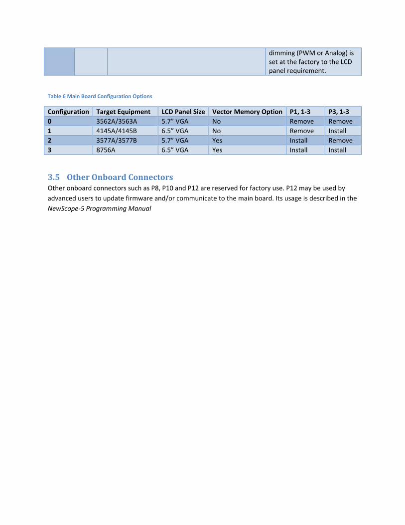
Table 6 Main Board Configuration Options
Configuration Target Equipment LCD Panel Size Vector Memory Option P1, 1-3 P3, 1-3 0 3562A/3563A 5.7” VGA No Remove Remove 1 4145A/4145B 6.5” VGA No Remove Install 2 3577A/3577B 5.7” VGA Yes Install Remove 3 8756A 6.5” VGA Yes Install Install
3.5 Other Onboard Connectors Other onboard connectors such as P8, P10 and P12 are reserved for factory use. P12 may be used by advanced users to update firmware and/or communicate to the main board. Its usage is described in the NewScope-5 Programming Manual

Revision History
Revision Date Notes 1.0 7/30/2014 Initial revision for serial numbers NS51000 and above 1.1 10/25/2014 Added 4145A and 8756A installation pictures. Updated Table 5 Jumper
Settings. Added Table 6 Main Board Configuration Options. 1.2 3/29/2015 Updated kit content table with pre-assembly information. Added
section 2.2.1 Read before installation. Updated jumper P17 pin positions in Table 5 Jumper Settings.