new york city transit authority (nycta) wire and …
TRANSCRIPT

NEW YORK CITY TRANSIT AUTHORITY (NYCTA)
WIRE AND CABLE SPECIFICATIONS
Specification RG Coaxial and Antenna Cables
February 4, 2011

New York City Transit Authority (NYCTA) Specification RG Coaxial and Antenna Cables Issue No. 5
February 4, 2011
2
TABLE OF CONTENTS 1 INTRODUCTION5
1.1 SCOPE ............................................................................................................................................ 5 1.2 ORGANIZATION.............................................................................................................................. 6
2 GENERAL INFORMATION 7 2.1 NYCTA TGN SPECIFICATIONS .................................................................................................... 7 2.2 SAFETY.......................................................................................................................................... 7 2.3 QUALITY ASSURANCE PROGRAM .................................................................................................. 7 2.4 WIRE AND CABLE PRODUCT QUALIFICATION ................................................................................ 9 2.5 PRODUCT TEST PROCEDURES AND TEST CONDITIONS ................................................................... 9
3 TECHNICAL REQUIREMENTS 10 3.1 CONDUCTOR REQUIREMENTS ...................................................................................................... 10
3.1.1 Conductor Materials ....................................................................................................................... 10 3.1.2 Copper Adhesion ............................................................................................................................. 10 3.1.3 Copper Ductility .............................................................................................................................. 10 3.1.4 Conductor Dimensions .................................................................................................................... 11 3.1.5 Conductor Joints ............................................................................................................................. 11
3.2 DIELECTRIC INSULATION REQUIREMENTS ................................................................................... 11 3.2.1 Dielectric Material Requirements .................................................................................................. 11 3.2.2 Dielectric Shrinkback ..................................................................................................................... 11 3.2.3 Thermal Stability - Oxidative Induction Time (OIT) ....................................................................... 12 3.2.4 Shear Adhesion................................................................................................................................ 12 3.2.5 Insulation Imperfections.................................................................................................................. 12
3.3 OVERALL SHIELD – OUTER CONDUCTOR..................................................................................... 13 3.3.1 Shields for Flexible Coaxial Cables ................................................................................................ 13 3.3.2 Laminating Shielding Tape ............................................................................................................. 13 3.3.3 Braid Wire ....................................................................................................................................... 13
3.4 JACKET ........................................................................................................................................ 13 3.4.1 Jacket Materials .............................................................................................................................. 13 3.4.2 Jacket Thickness and Eccentricity................................................................................................... 18 3.4.3 Diameter Over Jacket - Coaxial Cables.......................................................................................... 18 3.4.4 Light Absorption Test – UV Resistance........................................................................................... 20 3.4.5 Jacket Shrinkback Test .................................................................................................................... 20 3.4.6 Rodent Protection............................................................................................................................ 20 3.4.7 Flooding Compound under Jacket .................................................................................................. 20
3.5 COMPLETED CABLE - ELECTRICAL REQUIREMENTS .................................................................... 20 3.5.1 Continuity and Shorts...................................................................................................................... 20 3.5.2 DC Loop Resistance ........................................................................................................................ 20 3.5.3 Impedance - Coaxial Cables ........................................................................................................... 21 3.5.4 Capacitance – Coaxial Cables ........................................................................................................ 21 3.5.5 Structural Return Loss (SRL) - Coaxial Cables .............................................................................. 22 3.5.6 Attenuation – Coaxial Cables.......................................................................................................... 22 3.5.7 Impedance – Antenna Cable............................................................................................................ 23 3.5.8 Capacitance – Antenna Cable ......................................................................................................... 23 3.5.9 Attenuation – Antenna Cable........................................................................................................... 23 3.5.10 Coupling Loss – Radiating Antenna Cables ............................................................................... 24 3.5.11 Velocity of Propagation .............................................................................................................. 24 3.5.12 Shield Heating Test ..................................................................................................................... 24 3.5.13 Dielectric Strength Between Conductors .................................................................................... 24 3.5.14 Jacket Leakage Test - Coaxial Cables ........................................................................................ 25

New York City Transit Authority (NYCTA) Specification RG Coaxial and Antenna Cables Issue No. 5
February 4, 2011
3
3.5.15 Insulation Resistance .................................................................................................................. 25 3.6 COMPLETE CABLE - MECHANICAL REQUIREMENTS..................................................................... 26
3.6.1 Cold Bend........................................................................................................................................ 26 3.6.2 Cable Impact ................................................................................................................................... 26 3.6.3 Heat Aging Test ............................................................................................................................... 26 3.6.4 Water Absorption Test..................................................................................................................... 26
3.7 FLAMMABILITY REQUIREMENTS.................................................................................................. 26 3.8 COMPATIBILITY WITH HARDWARE .............................................................................................. 27 3.9 SHIPPING, PACKING AND MARKING ............................................................................................. 27
3.9.1 Cable Marking................................................................................................................................. 27 3.9.2 Reel Label........................................................................................................................................ 27 4 SPECIFIC CABLE PRODUCT REQUIREMENTS 28
4.1 FLEXIBLE AND SEMIRIGID COAXIAL CABLES............................................................................... 28 4.2 SLOTTED COAXIAL ANTENNA CABLES ........................................................................................ 29 4.3 TRIAXIAL ANTENNA CABLES....................................................................................................... 30 4.4 COAXIAL TRANSMISSION OR ANTENNA (NON-RADIATING) CABLES ........................................... 31 4.5 INTRABUILDING COAXIAL CABLES .............................................................................................. 31 4.6 ELEVATOR TRAVELING CABLES .................................................................................................. 33
5 REFERENCES 34

New York City Transit Authority (NYCTA) Specification RG Coaxial and Antenna Cables Issue No. 5
February 4, 2011
4
LIST OF TABLES Table 2-1. Qualification Tests for Coaxial and Antenna Cable ..................................................................... 7 Table 3-1. Center Conductor Elongation and Nominal Diameters .............................................................. 11 Table 3-2. Shear Adhesion of Dielectric....................................................................................................... 12 Table 3-3. Spark Test Requirements............................................................................................................. 12 Table 3-4. Jacket Material Requirements for Inside Cable.......................................................................... 14 Table 3-5. Polyethylene Cable Jacket Requirements.................................................................................... 15 Table 3-6. Non-Halogen Thermoset Cable Jacket Requirements................................................................. 16 Table 3-7. Non-Halogen Thermoplastic Cable Jacket Requirements........................................................... 17 Table 3-8. Jacket Thickness.......................................................................................................................... 18 Table 3-9. Cable Overall Diameters (Diameter over Jacket)....................................................................... 19 Table 3-10. Maximum DC Loop Resistance at 20oC .................................................................................... 21 Table 3-11. Capacitance .............................................................................................................................. 21 Table 3-12. Minimum Structural Return Loss (SRL).................................................................................... 22 Table 3-13. Flexible Coaxial Cables - Maximum Attenuation in dB/100ft at 20oC...................................... 22 Table 3-14. RG-735 Coaxial Cable - Maximum Attenuation in dB/100ft at 20oC........................................ 22 Table 3-15. Semirigid Coaxial Cables - Maximum Attenuation in dB/100ft at 20oC ................................... 23 Table 3-16. Radiating Antenna Cables (*) - Maximum Attenuation @ 20oC............................................... 23 Table 3-17. Non-Radiating Antenna Cables (*) – Maximum Attenuation @ 20oC ...................................... 24 Table 3-18. Radiating Antenna Cables – Nominal Coupling Loss @ 20oC ................................................. 24 Table 4-1a. Flexible Coaxial Cable Product Table...................................................................................... 28 Table 4-1b. Semirigid Coaxial Cable Product Table ................................................................................... 29 Table 4-2. Slotted Coaxial Antenna Cable Product Table ........................................................................... 30 Table 4-3. Triaxial Antenna Cable Product Table ....................................................................................... 30 Table 4-4. Coaxial Transmission or Antenna (Non-Radiating) Cable Product Table ................................. 32 Table 4-5a. Intrabuilding Coaxial Cable Product Table.............................................................................. 31 Table 4-5b. Intrabuilding Plenum Coaxial Cable Product Table ................................................................ 32 Table 4-5c. Intrabuilding Plenum Flexible Coaxial Cable Product Table…………………………………….33 Table 4-5d. Application Matrix .................................................................................................................... 32 Table 4-6. Elevator Traveling Cable Product Table ................................................................................... 33

New York City Transit Authority (NYCTA) Specification RG Coaxial and Antenna Cables Issue No. 5
February 4, 2011
5
1 Introduction 1.1 Scope This specification stipulates the minimum requirements for coaxial cables and antenna wires operating at radio frequencies. This specification applies to flexible and semirigid coaxial cables for low-loss, stable operation at radio frequencies and to antenna cables. These cable products are used for closed circuit television, radio communication and antenna cable connections to facilitate general communications services and surveillance throughout the NYCTA transit system. These cables are used in various outside and tunnel applications, placed in conduits, closets and other enclosures. These cables run along tunnel walls, between floors of stations and connect antenna dishes to receiving stations. They supply communications to numerous token booths and switch control locations across the system. This specification covers mechanical, electrical, insulation, and other properties that are required of these coaxial and antenna cables used by New York City Transit Authority (NYCTA) and is intended to stipulate the minimum requirements for the following cable products.
• Flexible and Semirigid Coaxial Cable - These Coaxial Cable products are used for closed circuit television (CCTV) and video communications. These cables are used in various outside and tunnel applications, placed in conduits, closets and other enclosures.
• Slotted Coaxial Antenna Cable - This radiating cable product is used to facilitate radio communications (transmission/reception) in the tunnels. The basic cable design consists of a coaxial cable with a slot in the outer conductor to allow for control release and reception of the signal (RF energy).
• Triaxial Antenna Cable - This radiating cable product is a product that uses a non-continuous outer conductor to facilitate radio communications (transmission/reception) in tunnels. The basic cable design consists of a coaxial cable with an outer conductor divided into non-contiguous segments. The RF signal can then be broadcast or be received through the gap between outer conductor semi-circular segments.
• Coaxial Transmission Line or Non-Radiating Antenna Cable - This non-radiating transmission line is utilized for transmission of RF energy between transmitting/receiving components of radio communications systems in buildings/tunnels and outdoors.
• Intrabuilding Coaxial Cable - These coaxial cables are designed for inside building applications. These cables would be placed inside building, along walls, between floors (risers), in plenums, inside closets and in ducts/conduits.
• Elevator Traveling Cables – These elevator traveling cables are equipped with video and provide signal and communications for CCTV video camera, passenger assistance intercom, and sound powered telephone for elevator maintenance. These cables consist of two coaxial units plus twisted pairs of shielded 20 AWG conductors under a single jacket sheath. The cables travel with the elevator and require flexural strength and endurance.

New York City Transit Authority (NYCTA) Specification RG Coaxial and Antenna Cables Issue No. 5
February 4, 2011
6
1.2 Organization The information contained in this document is divided into five principal sections.
Section 1. Introduction covering scope and organization of document Section 2. General Information on product, applications and quality assurance. Section 3. Technical Product Qualification Requirements - covering mechanical,
electrical, materials, flammability and marking requirements for cables. Section 4. Individual Cable Product Specifications and Product Tables Section 5. List of References
New York City Transit Authority (NYCTA) Specification RG Coaxial and Antenna Cables Issue No. 5
February 4, 2011
7
2 General Information This RG Specification provides product manufacturers a view of generic requirements for wire and cables intended for use by the NYCTA in their distribution and premises environments.
2.1 NYCTA TGN Specifications The latest edition and latest addendum of NYCTA Specification TGN, “New York City Transit Authority Wire and Cable Specifications - General Provisions and Definitions” is considered a part of this specification. If there is a conflict or difference between the criteria of this specification and other specifications mentioned herein, the requirements of this specification shall apply, unless otherwise stated herein. Some relevant segments of the TGN specification, “General Provisions and Definitions” of the NYCTA have been incorporated into this document.
2.2 Safety Cable and wire materials and all materials recommended by the manufacturer for use in splicing, placing, and maintenance shall be dermatologically safe and present no environmental hazards. In addition, all recommended materials and procedures shall comply with OSHA, EPA and FCC standards or applicable federal laws and regulations. Some test procedures specified in this document may be potentially hazardous to personnel. Safety procedures and precautions shall be followed to prevent damage to life and property.
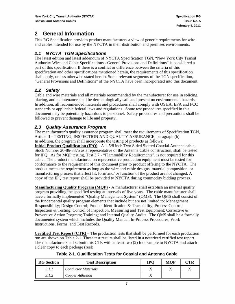
2.3 Quality Assurance Program The manufacturer’s quality assurance program shall meet the requirements of Specification TGN, Article II - TESTING, INSPECTION AND QUALITY ASSURANCE, paragraph (b). In addition, the program shall incorporate the testing of products as follows: Initial Product Qualification (IPQ) - A 1-5/8 inch Two Sided Slotted Coaxial Antenna cable, Stock Number 20-86-3375 as a representative of the Antenna Cable construction, shall be tested for IPQ. As for MQP testing, Test 3.7 - “Flammability Requirements”, is not required for this cable. The product manufactured on representative production equipment must be tested for conformance to the requirement of this document prior to product offering to the NYCTA. The product meets the requirement as long as the wire and cable designs, material composition, or manufacturing process that affect fit, form and/ or function of the product are not changed. A copy of the IPQ test report shall be provided to NYCTA during commodity bidding process. Manufacturing Quality Program (MQP) - A manufacturer shall establish an internal quality program providing the specified testing at intervals of five years. The cable manufacturer shall have a formally implemented "Quality Management System" (QMS). The QMS shall consist of the fundamental quality program elements that include but are not limited to: Management Responsibility; Design Control; Product Identification & Traceability; Process Control; Inspection & Testing; Control of Inspection, Measuring and Test Equipment; Corrective & Preventive Action Program; Training; and Internal Quality Audits. The QMS shall be a formally documented system which includes the Quality Manual, In-Process Procedures, Work Instructions, Forms, and Test Records. Certified Test Report (CTR) – The production tests that shall be performed for each production run are shown on Table 2-1. These test results shall be listed in a notarized certified test report. The manufacturer shall submit this CTR with at least two (2) foot sample to NYCTA and attach a clear copy to each package (reel).
Table 2-1. Qualification Tests for Coaxial and Antenna Cable
RG Section Test Description IPQ MQP CTR 3.1.1 Conductor Materials X X X 3.1.2 Copper Adhesion X

New York City Transit Authority (NYCTA) Specification RG Coaxial and Antenna Cables Issue No. 5
February 4, 2011
8
RG Section Test Description IPQ MQP CTR 3.1.3 Copper Ductility X 3.1.4 Conductor Dimensions X X X 3.1.5 Conductor Joints X 3.2.1 Dielectric Material Requirements X X X 3.2.2 Dielectric Shrinkback X X 3.2.3 Thermal Stability - Oxidative Induction Time X X 3.2.4 Shear Adhesion X X 3.2.5 Insulation Imperfections X 3.3.1 Shields For Flexible Coaxial Cables X 3.3.2 Laminating Shielding Tape X 3.3.3 Braid Wire X 3.4.1 Jacket Materials X X 3.4.2 Jacket Thickness And Eccentricity X X X 3.4.3 Diameter Over Jacket - Coaxial Cables X X X 3.4.4 Light Absorption Test – UV Resistance X 3.4.5 Jacket Shrinkback Test X X 3.4.6 Rodent Protection X 3.4.7 Flooding Compound Under Jacket X 3.5.1 Continuity And Shorts X X 3.5.2 DC Loop Resistance X X X 3.5.3 Impedance - Coaxial Cables X X 3.5.4 Capacitance – Coaxial Cables X X 3.5.5 Structural Return Loss (SRL) - Coaxial Cables X X 3.5.6 Attenuation – Coaxial Cables X X 3.5.7 Impedance – Antenna Cable X X X 3.5.8 Capacitance – Antenna Cable X X 3.5.9 Attenuation – Antenna Cable X X X
3.5.10 Coupling Loss – Antenna Cables X X 3.5.12 Shield Heating Test X 3.5.13 Dielectric Strength Between Conductors X X 3.5.14 Jacket Leakage Test - Coaxial Cables X X 3.5.15 Insulation Resistance X 3.6.1 Cold Bend X X 3.6.2 Cable Impact X X 3.6.3 Heat Aging Test X X 3.6.4 Water Absorption Test X X 3.7 Flammability Requirements X

New York City Transit Authority (NYCTA) Specification RG Coaxial and Antenna Cables Issue No. 5
February 4, 2011
9
RG Section Test Description IPQ MQP CTR 3.8 Compatibility with Hardware X
3.9.1 Cable Marking X X 3.9.2 Reel Label X X
4 Specific Cable Product Requirements X X
2.4 Wire and Cable Product Qualification The manufacturer shall qualify the product prior to product offering and re-qualify thereafter to assess the product’s ability to meet the requirements in this document. If changes are made in the design, material composition, or manufacturing process that affect fit, form and/or function of the product, the manufacturer shall re-perform IPQ on the product. The cable or wire manufacturer shall qualify the product prior to product offering as indicated in Table 2-1 under the IPQ column. The product shall be qualified periodically thereafter (MPQ) every 5 years to assess its ability to meet the requirements in this document. A cable product consists of copper conductor, wire insulation, core wrapping materials and cable outer sheath or jacket materials, depending on the specific qualification test.
2.5 Product Test Procedures and Test Conditions For all test procedures described in this document, the test conditions shall be the standard atmospheric conditions 23 ± 5°C, and 20 - 70% relative humidity, unless otherwise stated. All measured and computed values are to be rounded to the number of decimal places given in the corresponding requirement using the procedures of ASTM E29-06B. All units are English, except for temperature, which is given in Centigrade. Where useful or for reasons of conventional usage, conditions or criteria will be specified in both international standard of units (SI) format often referred to as metric units as well as English units, e.g., 1 lbf (4.45 N).

New York City Transit Authority (NYCTA) Specification RG Coaxial and Antenna Cables Issue No. 5
February 4, 2011
10
3 Technical Requirements 3.1 Conductor Requirements
3.1.1 Conductor Materials The center conductor shall be smoothly drawn, circular in cross section, uniform in quality, and free from defects and shall meet the mechanical and electrical requirements of this document. The center conductor shall be one of the following.
(1) Solid pure annealed copper meeting the requirements of ASTM B3-07 and/or ASTM B152M-09.
(2) Solid copper-clad aluminum meeting the requirements of ASTM B566-04a, Class 10A.
(3) Solid copper clad steel - meeting the requirements of ASTM B452-09 with a composite resistivity measured as per ASTM B193-02 (2008) at 20oC not to exceed 9.58 microohm-centimeters.
(4) Copper tube meeting the requirements of ASTM B3-07 and/or ASTM B188-09.
The outer conductor(s) or shields shall meet the electrical and mechanical requirements of this document and shall be one of the following constructions.
(1) Welded seam copper tube (corrugated)
(2) Aluminum cylindrical tube - Alloys 1060, 1100, 1145 or 1350
(3) Copper braid with 90% coverage
(4) Combination of Laminated Aluminum foil tape and Aluminum Braid (34AWG wires)
(5) Combination of Bonded Aluminum/Polyester/Aluminum tape and Tinned Copper Braid
(6) Slotted Conductor Radiating Antenna Cables - Overlapping copper strip with pre-punched apertures or slots
(7) Triaxial Antenna Cables - Two isolated overlapping shields of polyester-coated aluminum separated by a polyolefin interlayer
Conductors shall meet the quality requirements of ASTM B3-07 except that requirements for dimension, elongation, and permissible variations are superseded by this document.
3.1.2 Copper Adhesion Copper clad steel and aluminum conductors shall be constructed so as to form a metallurgical bond between the copper and the underlying substrate. The cable shall be twisted so that twenty 360-degree twists are made in length of cable equal to 100 times the outer diameter (OD) of the cable. After twisting the adhesion of copper to the steel and aluminum conductor shall be visually examined and no cracks or separation of the copper coating from the substrate is allowed.
3.1.3 Copper Ductility The copper coating shall be applied to the steel and aluminum conductors so as to form a ductile metallic layer. The cable shall be wound 5 turns around a mandrel with a diameter 1.5 times the outer diameter (OD) of the cable, at 1 turn per second. If no surface cracks are observed after this stress, the copper is considered to have the required ductility.

New York City Transit Authority (NYCTA) Specification RG Coaxial and Antenna Cables Issue No. 5
February 4, 2011
11
3.1.4 Conductor Dimensions The conductor shall be solid or tubular as indicated in Section 4 of this specification and where applicable shall meet the following dimensional requirements.
Table 3-1. Center Conductor Nominal Diameters
Center Conductor Cable Nominal Conductor Diameter Inches (mm)
Copper Clad Steel RG-59 (22AWG) 0.025 (0.64)
Copper Clad Steel RG-59 (20AWG) 0.032 (0.81)
Copper Clad Steel RG-6 0.040 (1.02)
Copper Clad Steel RG-7 0.051 (1.29)
Copper Clad Steel RG-11 0.064 (1.63)
Silver Plated Solid Copper RG-735 0.016 (0.40)
Copper Clad Aluminum RG-336 0.166 (4.22)
Copper Tube RG-323 0.309 (7.85)
Copper Clad Aluminum 500 Series 0.109 (2.77)
Copper Clad Aluminum 750 Series 0.166 (4.22)
Copper Clad Aluminum 875 Series 0.194 (4.93)
3.1.5 Conductor Joints No factory joints are allowed after the final draw to size, and conductors shall be uniform, clean, free from kinks, scales and other flaws.
3.2 Dielectric Insulation Requirements
3.2.1 Dielectric Material Requirements The dielectric shall be a foamed or solid polyolefin insulation grade containing no regrind, recycle or reprocessed material. The dielectric material is typically foamed from a blend of polyolefins that meet the requirements of Type I, III and IV materials listed in ASTM D1248-05. For plenum rated intrabuilding cables, fluoro-ethylene-polymers (FEP) materials that meet the requirements of ASTM D-2116-07 (before foaming) or tetrafluoroethylene (TFE) materials that meet the requirements of ASTM D4894-07, D4895-04 shall be used to meet the flammability requirements of these cables. The dielectric material shall be a suitable plastic dielectric material such that the mechanical and electrical requirements of this specification can be met. The exact choice of insulation material is determined by the cable application environment, desired flammability rating and or other performance criteria specified of this document.
3.2.2 Dielectric Shrinkback As per ASTM D4565-04, six-inch cable samples shall be conditioned (aged)
• at 85 oC (185 oF) for 4 hours - foamed or solid polyolefin dielectric • at 120 oC (248 oF) for 4 hours - foamed FEP or TFE dielectric
After cooling to room temperature, the cables will have less than 3/8" total shrinkback of dielectric along center conductor. Total shrinkback equals the sum of shrinkback from both cable ends.
New York City Transit Authority (NYCTA) Specification RG Coaxial and Antenna Cables Issue No. 5
February 4, 2011
12
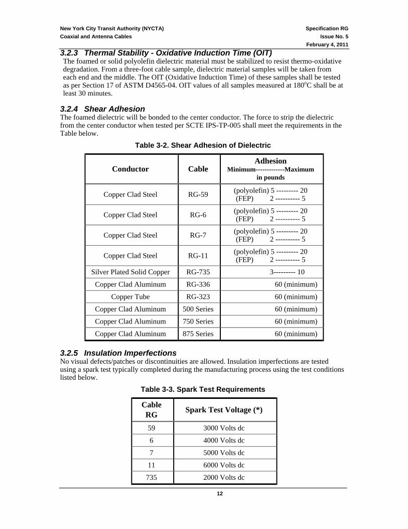
3.2.3 Thermal Stability - Oxidative Induction Time (OIT) The foamed or solid polyolefin dielectric material must be stabilized to resist thermo-oxidative degradation. From a three-foot cable sample, dielectric material samples will be taken from each end and the middle. The OIT (Oxidative Induction Time) of these samples shall be tested as per Section 17 of ASTM D4565-04. OIT values of all samples measured at 180oC shall be at least 30 minutes.
3.2.4 Shear Adhesion The foamed dielectric will be bonded to the center conductor. The force to strip the dielectric from the center conductor when tested per SCTE IPS-TP-005 shall meet the requirements in the Table below.
Table 3-2. Shear Adhesion of Dielectric
Conductor Cable Adhesion
Minimum-------------Maximum in pounds
Copper Clad Steel RG-59 (polyolefin) 5 --------- 20 (FEP) 2 ---------- 5
Copper Clad Steel RG-6 (polyolefin) 5 --------- 20 (FEP) 2 ---------- 5
Copper Clad Steel RG-7 (polyolefin) 5 --------- 20 (FEP) 2 ---------- 5
Copper Clad Steel RG-11 (polyolefin) 5 --------- 20 (FEP) 2 ---------- 5
Silver Plated Solid Copper RG-735 3--------- 10
Copper Clad Aluminum RG-336 60 (minimum)
Copper Tube RG-323 60 (minimum)
Copper Clad Aluminum 500 Series 60 (minimum)
Copper Clad Aluminum 750 Series 60 (minimum)
Copper Clad Aluminum 875 Series 60 (minimum)
3.2.5 Insulation Imperfections No visual defects/patches or discontinuities are allowed. Insulation imperfections are tested using a spark test typically completed during the manufacturing process using the test conditions listed below.
Table 3-3. Spark Test Requirements
Cable RG Spark Test Voltage (*)
59 3000 Volts dc
6 4000 Volts dc
7 5000 Volts dc
11 6000 Volts dc
735 2000 Volts dc

New York City Transit Authority (NYCTA) Specification RG Coaxial and Antenna Cables Issue No. 5
February 4, 2011
13
(*) or equivalent ac voltage
3.3 Overall Shield – Outer Conductor The outer conductor(s) or shields shall meet the mechanical requirements of this document and shall be one of the constructions listed in Section 3.1.1 of this specification. Quad and Tri-shield designs provides enhanced electrical and mechanical protection which is required for applications in transit systems where power cables and communications cables are often close together.
3.3.1 Shields for Flexible Coaxial Cables The basic shielding for RG-59, RG-6, RG-7 and RG-11 cables are as follows - Standard has an 18% min overlap on aluminum tape layer plus 34 AWG braid wires with 59% minimum coverage, all bonded to dielectric material. Tri-shield consists of the Standard Shield listed above plus an outer laminated shielding tape same as inner shield except the tape will not be bonded. Quad Shield consists of the Tri-Shield described above plus another outer shielding braid. To minimize interference currents, EMI/EMF ingress from the high voltage track and signaling lines, the RG-59, RG-6, RG-7 and RG-11 coaxial cables for NYCTA applications shall use Quad-Shielding as basic design with Tri-Shielding used in locations where exposure to electromagnetic fields is low. RG-735 cables will have outer conductor or shield of an aluminum-laminated foil and a tinned copper braid.
3.3.2 Laminating Shielding Tape Laminating shield tapes will consist of aluminum foil or laminated aluminum with bonding resin. The bare aluminum tape shall be Alloy 1100, 1145, 1200 or 1235 in accordance with ASTM B-736-02, Type I, Class 2. The total thickness of the laminated tape (without adhesive) shall be 0.0016 to 0.0020 inch thick.
3.3.3 Braid Wire Braid wires used in shielding shall be either (a) solid aluminum wires meeting requirements of ASTM B211-03 or B398-02. Allowable
alloys include Alloy 5056, Alloy 5201, Alloy 5154, Alcad 5056 or Alcad 6201 with a tensile strength of 43,000psi and tensile elongation of 3 % (ASTM B557-06), or
(b) copper braid wires meeting all the requirements of ASTM E37-05 for tinned copper conductors.
3.4 Jacket For outdoor applications, UV resistance is required. A low-smoke, low-toxicity, non-halogen outer jacket is for most applications and is required for cables placed in tunnels and stations. In addition, the cable jacket shall meet the mechanical requirements of Section 3.7 and product specific criteria in Section 4 of this specification.
3.4.1 Jacket Materials Jackets shall be applied to the cable core consistent with good commercial practice and shall be free from defects. Jacketing materials shall have a thickness of 0.025-inch minimum and an eccentricity less than 43%. The jacket materials may include, but are not limited to, the following:
1. Low-Smoke, Low-Toxicity Non-Halogen Material (e.g., Metal-Hydroxide Filled Polyolefins)
2. Polyethylene (polyolefin) Thermoplastic per ASTM D1248-05. 3. Fluorinated ethylene/propylene copolymer (FEP), Type I per ASTM D2116-07.

New York City Transit Authority (NYCTA) Specification RG Coaxial and Antenna Cables Issue No. 5
February 4, 2011
14
4. Polytetrafluoroethylene (PTFE) fluorocarbon per ASTM D4894-07, D4895-04, D1535-08.
5. Vinyl Thermoplastic per ASTM D2287-01. 6. UV resistance (outdoor applications).
Table 3-4. Jacket Material Requirements for Inside Cable
Minimum Requirements Property (Measured as
per ASTM D-4565)
Polyethylene or Vinyl
Thermoplastics
Non-Halogen Thermosets &
Thermoplastics
FEP Plastics
PTFE Plastics
Tensile Strength Unaged
2,000 psi (13.8 MPa)
1,500 psi (10.4 MPa)
2,500 psi (17.2 MPa)
4,000 psi (27.6 MPa)
Ultimate Elongation (% Minimum)
150 % 150% 200% 200%
Aging Requirements
10 days 100 ± 2°C
10 days 100 ± 2°C
10 days 100 ± 2°C
10 days 100 ± 2°C
Tensile Strength Aged (% of original)
> 85% > 75% > 75% > 85%
Ultimate Elongation (% of original)
> 50% > 75% > 75% > 85%
Table 3-4 provides property requirements for a selection of the jacket materials typically used for intra-building and premises cable applications. Tables 3-5, 3-6 and 3-7 contain detailed requirements for cable jacket materials used in NYCTA outside plant applications (e.g., tunnel and outdoor locations). Specific requirements are based on the particular outside cable application and use environment with two basic jacket designations for outside plant applications.
A. Polyethylene type jackets for outside plant applications where fire risk is low such as outdoor stations and similar locations (Table 3-5).
B. Low-smoke, non-halogen type jackets for applications inside subway tunnels or station spaces where human exposure to combustion products is a significant risk (Table 3-6 and 3-7).

New York City Transit Authority (NYCTA) Specification RG Coaxial and Antenna Cables Issue No. 5
February 4, 2011
15
Table 3-5. Polyethylene Cable Jacket Requirements
Requirement Test Method Jacket Property
MDPE HDPE ASTM
Material Description Type II, Class C Category 3, 4, or
5, Grade J4 Type III, Class C Category 5
D1248-05
Ultimate Elongation Unaged
≥ 400 % ≥ 400 % D4565-04
Ultimate Elongation Aged
≥ 375 % ≥ 375 % D4565-04
Yield Strength Minimum ≥ 11.0 MPa (1600 psi)
≥ 16.5 MPa (2400 psi) D4565-04
Carbon Black 20 nm or less average particle size 2.60 ± 0.25% 2.60 ± 0.25% ----
Light Absorption Coefficient 400 400 D349-06
Minimum Oxidative Induction Time at 199°±1°C (390°±2°F)
20 min
20 min
D3895-07
Environmental Stress Crack Resistance
0/1(Failures Allowed)
0/1(Failures Allowed) D45651-04
Jacket Shrinkback Oven Temp. °C Conditioning Shrinkback (Maximum %)
115 ±2 4 hours
5 %
115 ±2 4 hours
5 %
D4565-04
Water Absorption, Gravimetric Method 168 hours at 70°C (max)mg./in.2
< 35 < 35 ASTM D470-05
_________________________ 1 The complete cable may be substituted for a jacket specimen by wrapping the sample round a mandrel (10X diameter of cable) and immersing the sample as required in ASTM D 4565.

New York City Transit Authority (NYCTA) Specification RG Coaxial and Antenna Cables Issue No. 5
February 4, 2011
16
Table 3-6. Non-Halogen Thermoset Cable Jacket Requirements
Jacket Property Requirement Test Method
Tensile Strength (Unaged) Elongation (minimum %)
≥ 1500 psi ≥ 150 %
ASTM D4565-04
Aged samples for 168 hrs. at 100°C. Tensile Strength (min % of Unaged) Elongation (min % of Unaged)
≥ 60 % ≥ 60 %
ASTM D573-04
Creep Test Test temperature 200 oC ICEA T-28-562 Hot creep elongation < 50 % Hot creep set < 10 % Water Absorption, Gravimetric Method 168 hours at 70°C (max) mg./in.2
< 35 ASTM D470-05
Tensile Strength and Elongation after Fluid Immersion in
Retain ≥ 60 % of original strength and elongation
after
ASTM D471-06
Lubricating Oil (Mil-L-23699) 8 hrs @ 68-70°C Hydraulic Fluid (Mil-H-5606) 8 hrs @ 48-50°C Gasoline 8 hrs @ 20-22°C Water 8 hrs @ 68-70°C
Durometer - Shore A ≥ 80 ASTM D2240-05
Limiting Oxygen Index ≥ 32 ASTM D2863-06
Tear Resistance (min) lbf/in ≥ 35 ≥ 35
ASTM D624-00 ASTM D470-05
Smoke Generation Flaming Avg. Ds after 4 min. Flaming Avg. Dm Non-flaming Avg. Ds after 4 min. Non-flaming Avg. Dm
< 50
< 250 < 50
< 300
ASTM E662-06
Smoke Index ≤ 25 NES 711, Issue 2
Toxicity Index ≤ 5 NES 713, Issue 3
Acid Gas Equivalent Halogen Content
≤ 0.5 % ≤ 0.2 %
MIL-C24643, 1996

New York City Transit Authority (NYCTA) Specification RG Coaxial and Antenna Cables Issue No. 5
February 4, 2011
17
Table 3-7. Non-Halogen Thermoplastic Cable Jacket Requirements
Jacket Property Requirement Test Method Tensile Strength (Unaged) Elongation (minimum %)
≥ 1500 psi ≥ 150 %
ASTM D4565-04, OR EN 50290-2-27
Aged samples for 168 hrs. at 100°C. Tensile Strength (min. % of Unaged) Elongation (min. % of Unaged)
≥ 60 % ≥ 60 %
ASTM D573-04, OR EN 60811-1-1 Part
9
Heat Distortion Max Deformation
1000 gm weight at 90oC < 25 % ICEA T-27-581, IEC 60811-3-1
Water Absorption, Gravimetric Method 168 hours at 70°C (max) mg./in.2
< 35 ASTM D470-05, OR 60811-1-3 Part 9.2
Tensile Strength and Elongation after Fluid Immersion in
Retain ≥ 60 % of original strength and
elongation after
ASTM D471-06, OR
Lubricating Oil (Mil-L-23699) 8 hrs @ 68-70°C EN 60811-2-1 Hydraulic Fluid (Mil-H-5606) 8 hrs @ 20-22°C Gasoline 8 hrs @ 20-22°C Water 8 hrs @ 68-70°C
Durometer - Shore A ≥ 80 ASTM D2240-05
Limiting Oxygen Index ≥ 32 ASTM D2863-06
Tear Resistance (min) lbf/in ≥ 35 ≥ 35
ASTM D624-00 ASTM D470-05
Smoke Generation Flaming Avg. Ds after 4 min. Flaming Avg. Dm Non-flaming Avg. Ds after 4 min. Non-flaming Avg. Dm
< 50
< 320 < 50
< 300
ASTM E662-06, OR IEC 61034-1/-2 (for
the whole cable)
Smoke Index ≤ 25 NES 711, Issue 2, OR IEC 61034
Toxicity Index ≤ 5 NES 713, Issue 3
Acid Gas Equivalent Halogen Content
≤ 0.5 % ≤ 0.2 %
MIL-C24643, 1996, OR IEC 60754-1, IEC
60754-2
New York City Transit Authority (NYCTA) Specification RG Coaxial and Antenna Cables Issue No. 5
February 4, 2011
18
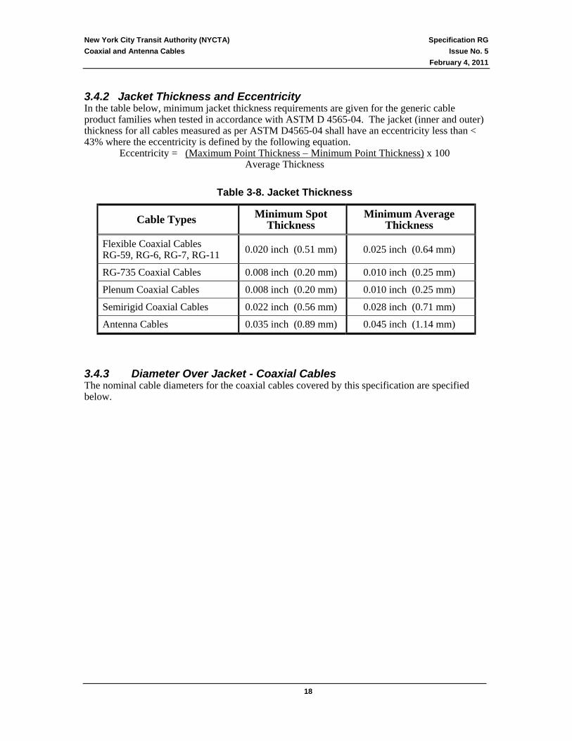
3.4.2 Jacket Thickness and Eccentricity In the table below, minimum jacket thickness requirements are given for the generic cable product families when tested in accordance with ASTM D 4565-04. The jacket (inner and outer) thickness for all cables measured as per ASTM D4565-04 shall have an eccentricity less than < 43% where the eccentricity is defined by the following equation.
Eccentricity = (Maximum Point Thickness − Minimum Point Thickness) x 100 Average Thickness
Table 3-8. Jacket Thickness
Cable Types Minimum Spot Thickness
Minimum Average Thickness
Flexible Coaxial Cables RG-59, RG-6, RG-7, RG-11 0.020 inch (0.51 mm) 0.025 inch (0.64 mm)
RG-735 Coaxial Cables 0.008 inch (0.20 mm) 0.010 inch (0.25 mm)
Plenum Coaxial Cables 0.008 inch (0.20 mm) 0.010 inch (0.25 mm)
Semirigid Coaxial Cables 0.022 inch (0.56 mm) 0.028 inch (0.71 mm)
Antenna Cables 0.035 inch (0.89 mm) 0.045 inch (1.14 mm)
3.4.3 Diameter Over Jacket - Coaxial Cables The nominal cable diameters for the coaxial cables covered by this specification are specified below.

New York City Transit Authority (NYCTA) Specification RG Coaxial and Antenna Cables Issue No. 5
February 4, 2011
19
Table 3-9. Cable Overall Diameters (Diameter over Jacket)
Cable Type Shielding Nominal Diameter over Jacket
RG-59 (22AWG) Copper Braid (100% coverage) 0.265 ± 0.01 inch (6.73 ± 0.25 mm)
RG-59 Tri-Shield 0.244 ± 0.01 inch (6.20 ± 0.25 mm)
Quad-Shield 0.265 ± 0.01 inch (6.73 ± 0.25 mm)
Quad Shield - Plenum (**) 0.235 ± 0.01 inch (5.97 ± 0.25 mm)
RG-6 Tri-Shield 0.278 ± 0.01 inch (7.06 ± 0.25 mm)
Quad-Shield 0.297 ± 0.01 inch (7.54 ± 0.25 mm)
Quad Shield - Plenum (**) 0.273 ± 0.01 inch (6.93 ± 0.25 mm)
RG-7 Tri-Shield 0.323 ± 0.01 inch (8.20 ± 0.25 mm)
Quad-Shield 0.340 ± 0.01 inch (8.64 ± 0.25 mm)
RG-11 Tri-Shield 0.400 ± 0.01 inch (10.16 ± 0.25 mm)
Quad-Shield 0.407 ± 0.01 inch (10.34 ± 0.25 mm)
Quad Shield - Plenum (**) 0.380 ± 0.01 inch (9.65 ± 0.25 mm)
RG-735 0.133 ± 0.01 inch (3.38 ± 0.2 mm)
500 Series (*) 0.560 to 0.600 inch (14.2 to 15.2 mm)
750 Series (*) 0.830 to 0.855 inch (21.1 to 21.7 mm)
875 Series (*) 0.945 to 0.955 inch (24.0 to 24.3 mm)
RG-366 0.60 ± 0.05 inch (15.0 ± 0.2 mm)
RG-323 1.10 ± 0.05 inch (27.9 ± 0.2 mm)
Antenna Cables (***) 1/2 inch
Corrugated Conductor Triaxial Conductor
0.73 inch (18.5 mm) - maximum 0.73 inch (18.5 mm) - maximum
Antenna Cables (***) 7/8 inch
Corrugated Conductor Triaxial Conductor
1.15 inch (29 mm) - maximum 1.20 inch (30 mm) - maximum
Antenna Cables (***) 1-1/4 inch
Corrugated Conductor Triaxial Conductor
1.60 inch (40 mm) - maximum 1.67 inch (42 mm) - maximum
Antenna Cables (***) 1-5/8 inch Corrugated Conductor 2.02 inch (51 mm) - maximum
(*) By definition, the diameter over the outer conductor is 1/2 inch, 3/4 inch and 7/8 inch
for the 500 Series, 750 Series and 875 Series coaxial cables, respectively. (**) Plenum cables constructed with fluoropolymer materials for fire resistance. (***) Antenna cable nominal sizes are diameter over foam dielectric.

New York City Transit Authority (NYCTA) Specification RG Coaxial and Antenna Cables Issue No. 5
February 4, 2011
20
3.4.4 Light Absorption Test – UV Resistance Cable jackets with outdoor applications with exposure to direct sunlight (UV radiation) shall be tested for UV resistance as per ASTM D3349-06 and have a minimum absorption coefficient of 400 for polyethylene jackets and 280 for all other jacket materials.
3.4.5 Jacket Shrinkback Test A six-inch cable section shall be conditioned for 4 hours (as per ASTM D4565-04) at
• 115 oC (239 oF) for non-halogen materials, polyolefins or vinyl thermoplastics • 150 oC (302 oF) for fluoropolymer materials
The cable sample will show no more than 5% shrinkback of jacket from cable core components.
3.4.6 Rodent Protection If additional rodent protection armor is needed for specific applications, the coaxial cable should be covered with a 0.006 inch thick corrugated armor tape (with 23 % overlap) made of either
(a) copper clad stainless steel tape meeting requirements of ASTM B694-03, or (b) copper clad alloy steel meeting requirements of ASTM B224-04 for Cu and ASTM
A505-05 for the steel.
3.4.7 Flooding Compound under Jacket If flooding compound is present under outer jacket to help provide enhanced corrosion shielding and moisture barrier, the flooding compound should have a drip point greater than 80oC.
3.5 Completed Cable - Electrical Requirements
3.5.1 Continuity and Shorts All conductors, metallic screens and shields shall be electrically continuous when tested in accordance with Sections 11, 12 and 30 of ASTM D4566-05.
3.5.2 DC Loop Resistance The DC loop resistance of coaxial cable with an overall shield shall be measured as per SCTE-IPS-TP-008. The maximum DC loop resistance shall be as follows:

New York City Transit Authority (NYCTA) Specification RG Coaxial and Antenna Cables Issue No. 5
February 4, 2011
21
Table 3-10. Maximum DC Loop Resistance at 20oC
Cable Type Shielding DC Loop Resistance in Ohms per Kft (ohm/Km)
RG-59 Tri-Shield 63.7 (209)
Quad-Shield 62.0 (203)
RG-6 Tri-Shield 43.0 (141)
Quad-Shield 41.4 (136)
RG-7 Tri-Shield 28.6 ( 94)
Quad-Shield 27.4 (90)
RG-11 Tri-Shield 18.8 (62)
Quad-Shield 17.8 (58)
500 Series 1.35 (4.4)
750 Series 1.0 (3.3)
875 Series 0.93 (3.0)
RG-366 1.2 (3.9)
RG-366 0.78 (2.5)
3.5.3 Impedance - Coaxial Cables The impedance of the coaxial cables shall be measured as per SCTE IPS-TP-006 or equivalent measurement method using a network analyzer equipped with appropriate reflection measurement device. The impedance value for the cables will be either 75±3 ohms or 50±2 ohms as prescribed in the product tables of Section 4 of this specification.
3.5.4 Capacitance – Coaxial Cables To meet the impedance and attenuation requirements of this specification, it is expected that the nominal capacitance of these cables shall be as follows –
Table 3-11. Capacitance
Cable Types Capacitance
Flexible Coaxial Cables RG-735, RG-59, RG-6, RG-7 and RG-11
16 to 18 picoFarads per foot (pF/ft) 52 to 59 picoFarads per meter (pF/m)
Semirigid Coaxial Cables - 500, 750 and 875 Series
15 to 17 picoFarads per foot (pF/ft) 49 to 56 picoFarads per meter (pF/m)

New York City Transit Authority (NYCTA) Specification RG Coaxial and Antenna Cables Issue No. 5
February 4, 2011
22
3.5.5 Structural Return Loss (SRL) - Coaxial Cables Structural return loss shall be measured as per SCTE-IPS-TP-007 or equivalent measurement method. The minimum SRL of the cable shall be as follows:
Table 3-12. Minimum Structural Return Loss (SRL)
Cable Types Minimum SRL (5-to-1000MHz)
Flexible Coaxial Cables - RG-59, RG-6, RG-7, RG-11 20dB requirement @ 5-1000 MHz
RG-735 Coaxial Cables 30dB requirement @ 15-90 MHz
Semirigid Coaxial Cables - 500, 750 and 875 Series
RG-366 and RG-323 30dB requirement @ 5-1000 MHz
3.5.6 Attenuation – Coaxial Cables The signal loss due to conductor and dielectric losses is defined as attenuation and is a function of frequency. The attenuation of the coaxial cables shall be measured as per SCTE-IPS-TP-009 or equivalent measurement method. The maximum attenuation values for coaxial cables are listed in the Tables below.
Table 3-13. Flexible Coaxial Cables - Maximum Attenuation in dB/100ft at 20oC
Frequency RG-59 Series RG-6 Series RG-7 Series RG-11 Series
5 MHz 1.22 0.81 0.57 0.38
55 MHz 2.06 1.60 1.27 1.03
211 MHz 3.94 3.08 2.45 2.01
330 MHz 4.96 3.89 3.10 2.55
550 MHz 6.47 5.09 4.07 3.36
750 MHz 7.62 6.00 4.81 3.99
1000 MHz 8.87 7.00 5.62 4.67
Table 3-14. RG-735 Coaxial Cable - Maximum Attenuation in dB/100ft at 20oC
Frequency Maximum Attenuation
1 MHz 0.6
5 MHz 1.2
10 MHz 1.7
50 MHz 3.8
100 MHz 5.5
200 MHz 7.8

New York City Transit Authority (NYCTA) Specification RG Coaxial and Antenna Cables Issue No. 5
February 4, 2011
23
Table 3-15. Semirigid Coaxial Cables - Maximum Attenuation in dB/100ft at 20oC
Frequency 500 Series 750 Series 875 Series
5 MHz 0.16 0.11 0.09
55 MHz 0.54 0.37 0.32
215 MHz 1.09 0.75 0.65
300 MHz 1.31 0.89 0.78
500 MHz 1.73 1.18 1.03
750 MHz 2.17 1.48 1.29
1000 MHz 2.53 1.74 1.53
3.5.7 Impedance – Antenna Cable The impedance of the antenna coaxial cables shall be measured as per SCTE IPS-TP-006 or equivalent measurement method using a network analyzer equipped with appropriate reflection measurement device. The impedance value for the antenna cables will be 50±2 ohms.
3.5.8 Capacitance – Antenna Cable To meet the impedance and attenuation requirements of this specification, it is expected that the nominal capacitance of these cables shall be 23 ± 0.5 pF/ft [75.5 ± 1.6 pF/m].
3.5.9 Attenuation – Antenna Cable The signal loss due to conductor and dielectric losses is defined as attenuation and is a function of frequency. The maximum attenuation values for antenna cables are listed below.
Table 3-16. Radiating Antenna Cables - Maximum Attenuation @ 20oC
Cable Size (*)
1/2 inch 1/2 inch 7/8 inch 1-1/4 inch 1-5/8 inch Frequency
Triaxial Conductor Slotted Conductor Triaxial / Slotted Conductor Slotted Cond.
150 MHz 1.5 dB/100ft 2.0 dB/100ft 0.55 dB/100ft 0.45 dB/100ft 0.40 dB/100ft
450 MHz 2.7 dB/100ft 5.0 dB/100ft 1.1 dB/100ft 0.90 dB/100ft 0.76 dB/100ft
900 MHz 4.0 dB/100ft 6.0 dB/100ft 1.65 dB/100ft 1.25 dB/100ft 1.21 dB/100ft.

New York City Transit Authority (NYCTA) Specification RG Coaxial and Antenna Cables Issue No. 5
February 4, 2011
24
Table 3-17. Non-Radiating Antenna Cables – Maximum Attenuation @ 20oC in (dB/100 Ft)
Cable Size(*) Frequency
1/2 inch 7/8 inch 1-1/4 inch 1-5/8 inch 2-1/4 inch
150 MHz 0.81 0.448 0.344 0.260 0.228
450 MHz 1.44 0.805 0.628 0.475 0.424
900 MHz 2.10 1.18 0.94 0.711 0.64
3.5.10 Coupling Loss – Radiating Antenna Cables Coupling loss is measured as referenced to a dipole at 20 ft (6m) perpendicular to the cable. The nominal coupling losses for antenna cables are listed below. Performance will vary depending on location and surrounding environments.
Table 3-18 Radiating Antenna Cables – Nominal Coupling Loss @ 20oC for 50% Reliability (**)
Median Coupling Loss Value
Slotted Conductor Cables (*) Frequency Triaxial Conductor Cables 1/2 inch 7/8 inch 1-1/4 inch 1-5/8 inch
150 MHz 75dB 70 dB 66 dB 70 dB 70 dB
450 MHz 75 dB 72 dB 75 dB 81 dB 83 dB
900 MHz 75 dB 75 dB 75 dB 80dB 82 dB
(*) Nominal sizes are of diameters over foam dielectric (**) For 95% reliability add 12 dB
3.5.11 Velocity of Propagation To meet the impedance and attenuation requirements of this specification, it is expected that the Velocity of Propagation (Vp) for these cables shall be as follows - Vp = 80 ± 2% for RG-735, RG-59, RG-6, RG-7 and RG-11 Flexible Coaxial cables Vp = 87 ± 2% for 500, 750 and 875 Series Semirigid Coaxial cables Vp = 88 ± 2% for Antenna Coaxial cables
3.5.12 Shield Heating Test The shield of the coaxial cable will be able to carry 60 Amp RMS for 15 minutes without going open or creating risk of fire.
3.5.13 Dielectric Strength Between Conductors When tested as per SCTE-IPS-TP-012, the dielectric strength between the center and outer conductors of the coaxial cable shall withstand 1000 volts at 60Hz ac (or 1500 volts DC) for one minute.

New York City Transit Authority (NYCTA) Specification RG Coaxial and Antenna Cables Issue No. 5
February 4, 2011
25
3.5.14 Jacket Leakage Test - Coaxial Cables The center 6-inches (150 mm) of a 12-inch (300mm) length of completed cable shall be completely covered in conductive foil. A 60-Hz AC potential shall be applied between the foil and the shield, gradually increasing the potential to 1500 volts AC over a period of 30 seconds and maintain the potential for 60 seconds. During the test period of 90 seconds, the current flowing (jacket leakage) shall not exceed 10 milli-amp (mA).
3.5.15 Insulation Resistance As per ASTM D4566-05, the insulation resistance between the center and outer conductors of the coaxial cable shall be minimum of 5000 megaohm-kft when measured with a DC potential of between 100 and 550 volts applied for 60 seconds insulation resistance.

New York City Transit Authority (NYCTA) Specification RG Coaxial and Antenna Cables Issue No. 5
February 4, 2011
26
3.6 Complete Cable - Mechanical Requirements This section covers mechanical requirements for communication cables for outdoor use and intended to be installed aerially, directly buried, or placed in the underground. Although the cable design requirements identified in this section apply to all cable structures, some individual jacketing requirements and National Electrical Code (NEC) requirements are listed for cables designated for specific applications. Cables used in the outside plant will be subjected to a wide range of temperatures. The cables covered by this document are expected to function within the following temperature limitations.
Operation: −40°C (−40°F) to +70°C (+158°F) Installation: −25°C (−13°F) to +60°C (+140°F)
Storage/Shipping:−40°C (−40°F) to +75°C (+167°F)
3.6.1 Cold Bend The completed cable shall be capable of meeting the bend test requirements of ASTM D 4565-04 when tested at −30±2°C after being conditioned at that temperature for 4 hours. Prior to visual inspection, any tested shielded-cable sample shall pass the attenuation requirement in this document. The cable may be allowed to come to room temperature before inspection. No evidence of cracking of the inner shields or outer cable jacket is allowed when viewed under normal or corrected-to-normal vision.
3.6.2 Cable Impact A suitable length of completed cable shall be conditioned at −30 ± 2°C for 4 hours. In accordance with ASTM D4565-04 (or per SCTE IPS-TP-003 or SCTE IPS-TP-001), this cable sample will be subjected to an impact force of a 1-pound weight (0.45kg) dropped from a height of 3 feet (0.9 m). After testing, the cable shall be allowed to stabilize at room temperature prior to inspection of the impacted area. No evidence of cracking of the inner shields or outer jackets is allowed when viewed under normal or corrected-to-normal vision.
3.6.3 Heat Aging Test Cables shall be aged for 14 days at 75oC and no more than 5% deviation in attenuation values as measured for attenuation requirements in this specification.
3.6.4 Water Absorption Test Cables shall be immersed in 70oC water for 168 hours as per ASTM D470-05 and show an absorption result of no more than 35 mg. / in.2.
3.7 Flammability Requirements The flammability and smoke requirements of cables can be greatly affected by the installation methods and procedures. The flammability requirements for a given product will depend upon the intended installation site and local environment for that product. Cables installed within buildings must comply with the requirements of the National Electrical Code (NEC) Article 800. The requirements in this section are for cables classified in accordance with NEC rating and the UL Listings for cables and do not apply to cables that are installed in accordance with the exceptions permitted in NEC Article 800. The basic performance for coaxial cables and non-radiating antenna cables will be riser rated fire resistance as defined below – • Intrabuilding, Riser - Cables intended for intrabuilding riser shall be Type MPR or CMR,
and NRTL Listed and meet the requirements of UL 1666 test. Coaxial cables specified designed for plenum applications will meet the following fire resistance standards -

New York City Transit Authority (NYCTA) Specification RG Coaxial and Antenna Cables Issue No. 5
February 4, 2011
27
• Plenum Cable - Cables intended for installations in environmental air handling spaces (plenums) shall be Type CMP, and NRTL Listed and meet the requirements of NFPA-262-07 “Standard Method of Test for Flame Travel and Smoke of Wires and Cables for use in Air-Handling Spaces” 2007 edition..
3.8 Compatibility with Hardware To help, ensure that the cables are properly installable, the cables shall be compatible with typical connecting interface and terminating hardware equipment. New sizes and types of hardware may be required for certain cable designs and it is desirable and expected that the cable manufacturer will work with NYCTA to resolve any installation hardware compatibility issues. It is especially noted that matching cables and connectors need to be identified and used so as to help ensure reliable efficient communications network.
3.9 Shipping, Packing and Marking All identification and marking shall be per the latest edition and addendum of NYCTA Specification TGN.
3.9.1 Cable Marking The cable marking shall be printed, with white characters on dark jackets and with black characters on light colored jackets, on the outer jacket at intervals of not more than two feet. Cable remarking must be approved by NYCT. If approved, remarking shall be printed with yellow characters on dark jackets and dark purple on light jackets. Each length of cable shall be marked with the following.
1. Name of manufacturer 2. Month/Year (e.g., 01/00) of manufacture 3. Type of cable / conductor and size (e.g., RG-11), stock number. 4. Characteristic Impedance (e.g. 75 Ohm, 50 Ohm). 5. Flammability resistance rating – CMR, CMP, etc. (if applicable). 6. Sequential footage numbers.
3.9.2 Reel Label Each reel of cable shall have a cable data sheet(s) and the certified test report (CTR). The data sheet(s) and the CTR shall be legible and packaged in a waterproof wrapping for protection against the elements. As a minimum, the data sheet(s) shall contain the following information.
1. Manufacturer's name and plant location. 2. Customer order number or factory order number. 3. NYCTA stock number. 4. Unique cable identifier (cable serial number: date of manufacture). 5. Length of cable. 6. Type of cable
• Central Conductor - size and material • Outer Conductor and Shields- size and material • Attenuation versus Frequency Data • Maximum voltage at which cable/wire can be used
7. Beginning and ending length markings 8. Weight of cable and reel – total weight and weight per foot of cable. 9. NYCTA Specification Version for the Cable.

New York City Transit Authority (NYCTA) Specification RG Coaxial and Antenna Cables Issue No. 5
February 4, 2011
28
4 Specific Cable Product Requirements The requirements of Section 3 provide the baseline mechanical and electrical performance for coaxial and antenna cable products supplied to NYCTA. This section lists the individual NYCTA Stock numbers for the various cable families and distinctive cable products and singular customized requirements for cable product families. All applicable requirements in Section 3 apply to all cable product families unless specifically excluded in the following product descriptions.
• Flexible and Semirigid Coaxial Cable • Slotted Coaxial Antenna Cable • Triaxial Antenna Cable • Coaxial Transmission or Antenna (Non-Radiating ) Cable • Intrabuilding Coaxial Cable • Elevator Traveling Cables
4.1 Flexible and Semirigid Coaxial Cables These Semirigid and Flexible Coaxial Cable products are used for closed circuit television (CCTV), video communications, radio communication and DS-3/DS-4 communications services. The cables are used in various outside and tunnel applications, placed in conduits, closets and other enclosures. Coaxial cables for intrabuilding and plenum applications are listed in section 4.5 below. The flexible cables have an inner conductor of solid copper or copper-clad steel surrounded by a solid or foam polyethylene dielectric, a copper braided outer conductor and an outer non-halogen black jacket material.
Table 4-1a. Flexible Coaxial Cable Product Table
NYCTA Stock Number
Cable Description
Nominal Diameter over Jacket Performance Details
20-86-1222 RG-59 (22AWG) with Quad Shield
0.265 inch (6.6 mm)
Impedance = 75-ohm Capacitance = 20.5pF/ft
Vp = 66%
20-86-1320 RG-59 (20AWG) with Quad Shield 0.315 inch Impedance = 75-ohm
20-86-1622 RG-6 Quad Shield 0.297 inch Impedance = 75-ohm
20-86-1722 RG-7 Quad Shield 0.340 inch Impedance = 75-ohm
20-86-1314 RG-11 Quad Shield 0.407 inch Impedance = 75-ohm
20-86-1735 RG-735 0.133 inch DS-3 / DS-4 Applications
New York City Transit Authority (NYCTA) Specification RG Coaxial and Antenna Cables Issue No. 5
February 4, 2011
29
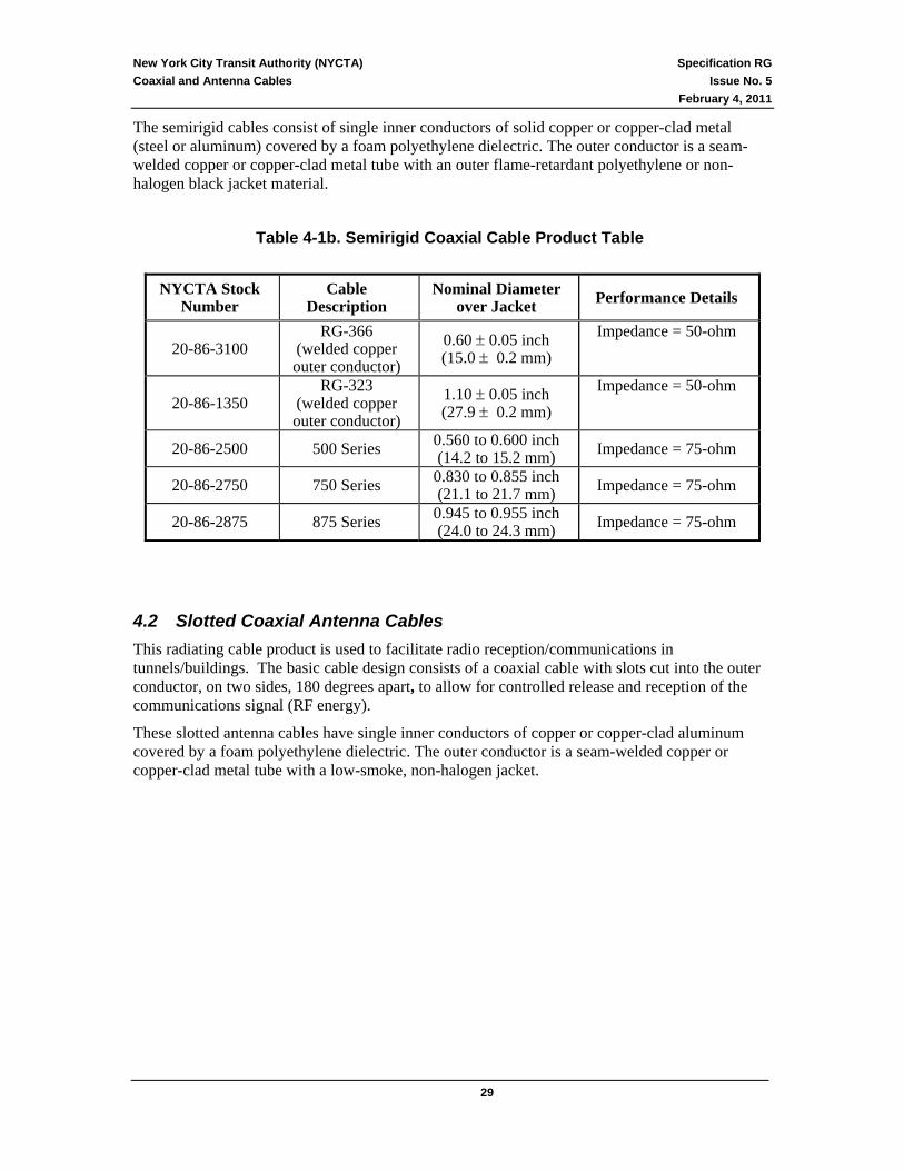
The semirigid cables consist of single inner conductors of solid copper or copper-clad metal (steel or aluminum) covered by a foam polyethylene dielectric. The outer conductor is a seam-welded copper or copper-clad metal tube with an outer flame-retardant polyethylene or non-halogen black jacket material.
Table 4-1b. Semirigid Coaxial Cable Product Table
NYCTA Stock Number
Cable Description
Nominal Diameter over Jacket Performance Details
20-86-3100 RG-366
(welded copper outer conductor)
0.60 ± 0.05 inch (15.0 ± 0.2 mm)
Impedance = 50-ohm
20-86-1350 RG-323
(welded copper outer conductor)
1.10 ± 0.05 inch (27.9 ± 0.2 mm)
Impedance = 50-ohm
20-86-2500 500 Series 0.560 to 0.600 inch (14.2 to 15.2 mm) Impedance = 75-ohm
20-86-2750 750 Series 0.830 to 0.855 inch (21.1 to 21.7 mm) Impedance = 75-ohm
20-86-2875 875 Series 0.945 to 0.955 inch (24.0 to 24.3 mm) Impedance = 75-ohm
4.2 Slotted Coaxial Antenna Cables This radiating cable product is used to facilitate radio reception/communications in tunnels/buildings. The basic cable design consists of a coaxial cable with slots cut into the outer conductor, on two sides, 180 degrees apart, to allow for controlled release and reception of the communications signal (RF energy).
These slotted antenna cables have single inner conductors of copper or copper-clad aluminum covered by a foam polyethylene dielectric. The outer conductor is a seam-welded copper or copper-clad metal tube with a low-smoke, non-halogen jacket.

New York City Transit Authority (NYCTA) Specification RG Coaxial and Antenna Cables Issue No. 5
February 4, 2011
30
Table 4-2. Slotted Coaxial Antenna Cable Product Table
NYCTA Stock Number Cable Description Maximum Diameter
over Jacket Performance Details
20-86-3200 Nominal 1/2 inch 0.73 inch Impedance = 50-ohm
20-86-3250 Nominal 7/8 inch 1.15 inch Impedance = 50-ohm Inner Conductor = Copper
20-86-3252 Nominal 7/8 inch 1.15 inch Impedance = 50-ohm
Inner Conductor = Copper-Clad Aluminum
20-86-3325 Nominal 1-1/4 inch 1.60 inch Impedance = 50-ohm
20-86-3375 Nominal 1-5/8 inch 2.02 inch Impedance = 50-ohm Inner Conductor = Copper
4.3 Triaxial Antenna Cables This radiating cable product is a product that uses a non-continuous outer conductor to facilitate radio reception/ communications in tunnels. The basic cable design consists of a coaxial cable with the outer conductor divided into overlapping, isolated segments. The RF signal can then be broadcast or be received through the gap between outer conductor circular segments.
These antenna cables have inner conductors of solid copper or copper-clad aluminum covered by a foam polyethylene dielectric. The outer conductors are copper or copper-clad aluminum materials with an outer jacket of low-smoke, non-halogen material. Dielectric interlayers between outer conductors are polyethylene.
Table 4-3. Triaxial Antenna Cable Product Table
NYCTA Stock Number Cable Description Maximum Diameter
over Jacket Performance Details
20-86-4300 Nominal 1/2 inch 0.73 inch Impedance = 50-ohm
20-86-4350 Nominal 7/8 inch 1.20 inch Impedance = 50-ohm
20-86-4127 Nominal 1-1/4 inch 1.67 inch Impedance = 50-ohm
New York City Transit Authority (NYCTA) Specification RG Coaxial and Antenna Cables Issue No. 5
February 4, 2011
31
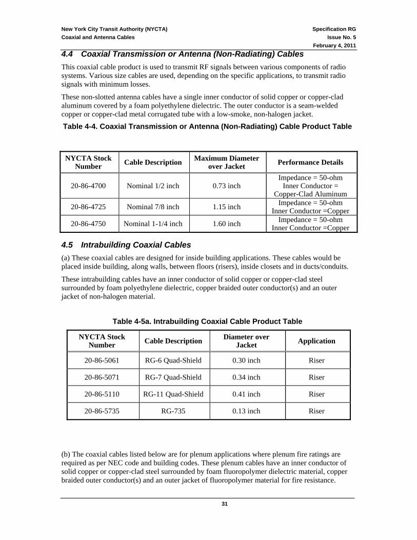
4.4 Coaxial Transmission or Antenna (Non-Radiating) Cables This coaxial cable product is used to transmit RF signals between various components of radio systems. Various size cables are used, depending on the specific applications, to transmit radio signals with minimum losses.
These non-slotted antenna cables have a single inner conductor of solid copper or copper-clad aluminum covered by a foam polyethylene dielectric. The outer conductor is a seam-welded copper or copper-clad metal corrugated tube with a low-smoke, non-halogen jacket.
Table 4-4. Coaxial Transmission or Antenna (Non-Radiating) Cable Product Table NYCTA Stock
Number Cable Description Maximum Diameter over Jacket Performance Details
20-86-4700 Nominal 1/2 inch 0.73 inch Impedance = 50-ohm
Inner Conductor = Copper-Clad Aluminum
20-86-4725 Nominal 7/8 inch 1.15 inch Impedance = 50-ohm Inner Conductor =Copper
20-86-4750 Nominal 1-1/4 inch 1.60 inch Impedance = 50-ohm Inner Conductor =Copper
4.5 Intrabuilding Coaxial Cables (a) These coaxial cables are designed for inside building applications. These cables would be placed inside building, along walls, between floors (risers), inside closets and in ducts/conduits.
These intrabuilding cables have an inner conductor of solid copper or copper-clad steel surrounded by foam polyethylene dielectric, copper braided outer conductor(s) and an outer jacket of non-halogen material.
Table 4-5a. Intrabuilding Coaxial Cable Product Table
NYCTA Stock Number Cable Description Diameter over
Jacket Application
20-86-5061 RG-6 Quad-Shield 0.30 inch Riser
20-86-5071 RG-7 Quad-Shield 0.34 inch Riser
20-86-5110 RG-11 Quad-Shield 0.41 inch Riser
20-86-5735 RG-735 0.13 inch Riser
(b) The coaxial cables listed below are for plenum applications where plenum fire ratings are required as per NEC code and building codes. These plenum cables have an inner conductor of solid copper or copper-clad steel surrounded by foam fluoropolymer dielectric material, copper braided outer conductor(s) and an outer jacket of fluoropolymer material for fire resistance.

New York City Transit Authority (NYCTA) Specification RG Coaxial and Antenna Cables Issue No. 5
February 4, 2011
32
Table 4-5b. Intrabuilding Plenum Coaxial Cable Product Table
NYCTA Stock Number Cable Description Nominal Diameter
over Jacket Application
20-86-6222 RG-59/U Quad Shield 0.26 inch Plenum
20-86-6320 RG-59/U Quad Shield 0.26 inch Plenum
20-86-6060 RG-6 Quad Shield 0.27 inch Plenum
20-86-6110 RG-11 Quad Shield 0.38 inch Plenum
(c) Flexible Coaxial Plenum cable - RG-59/U - one conductor, solid, Teflon FEP, HALAR, ECTFE, KYNAR FLEX or approved equivalent insulation and outer jacket, type RG-59/u flexible Coaxial cable, (2500 ft. Wooden reels).
Table 4-5c. Intrabuilding Plenum Flexible Coaxial Cable Product Table
NYCTA Stock Number
Cable Description
Size of Conductors,
AWG NEC
20-86-1225 RG-59/U 22 Article 800
20-86-1325 RG-59/U 20 Article 800
(d) These coaxial cables can support Ethernet and DS-3 /DS-4 type services. Table 4-5d below summaries the typical services for which these coaxial cables can be used.
Table 4-5d. Application Matrix
Application Description and Cabling Requirements
10 MHz Ethernet 10Base5 Service
10 MHz Ethernet service over 50-ohm coaxial cable with a typical reach of less than 500 meters
10 MHz Ethernet 10Broad 36 Service
10 MHz Ethernet service over 75-ohm coaxial cable with a typical reach of less than 3600 meters
Thin Ethernet 10Base2 Service
10 MHz Ethernet service over (RG-59 or RG-6) 50-ohm coaxial cable with a reach of less than 180 meters unless repeaters are used

New York City Transit Authority (NYCTA) Specification RG Coaxial and Antenna Cables Issue No. 5
February 4, 2011
33
4.6 Elevator Traveling Cables At stations, and other transit facilities, elevator traveling-cables carry signals and communications for CCTV video camera, passenger assistance intercom, and sound powered telephone for elevator maintenance. These cables consist of 2 RG-6 coaxial units and 13 pairs of individually shielded 20 AWG conductors under a single flame retardant jacket sheath with a riser fire rating. The cables travel with the elevator and need to be physically robust and have a long flex life. It consists of the following:
1. Thirteen pairs of individually shielded #20 AWG wire stranded conductor, as per signal code cable described in Section 4.1 of NYCTA Specification TSC used for signal switching; i.e., they carry low frequency signaling information. Stranded conductors with 7 strands per conductor that are insulated with polyethylene. These cables have an inner jacket of polyethylene or non-halogen material (50 mil nominal thickness) with a 5-mil copper shield for protection and isolation from electrical noise and interference, plus a final outer jacket of low-smoke low-toxicity no halogen material.
2. Two RG-6 coaxial units meeting the applicable requirements of this specification.
The above cable shall have an operating temperature range of -15oC to +60oC. For locations outside these operating conditions, other elevator cables can be used at the discretion of the NYCTA Engineer. For example, a cable with two RG-6 coaxial units and thirteen #20AWG twisted pairs jacketed with neoprene and rubbers can be used down to -40oC.
Table 4-6. Elevator Traveling Cable Product Table
NYCTA Stock Number Cable Description Application
20-78-7160 Two - RG-6
plus 13-pair 20 AWG
-15oC to +60oC Riser Fire Rating (CMR)
The elevator traveling cable shall comply with all applicable standards of the Underwriters Laboratories and shall be rated for use in low temperature environments.
Note: This Elevator Traveling Cable is mentioned also in TC #7 with the same stock number.
___________________________________________________

New York City Transit Authority (NYCTA) Specification RG Coaxial and Antenna Cables Issue No. 5
February 4, 2011
34
5 References NYCTA TGN Issue #7, November 1999
New York City Transit Authority Wire and Cable Specifications – General Provisions and Definitions
NYCTA Specification TC Issue #7, and TSC Issue #1 December 2009
New York City Transit Authority Wire and Cable Specification TC and TSC
ISO 9001: 2000 Quality Management System ASTM A505-05 Standard Classification Of Steel ASTM B3-07 Standard Specification for Soft or Annealed Copper Wire
ASTM B152M-09 Standard Specification for Copper Sheet, Strip, Plate, and Rolled Bar.
ASTM B188-09 Standard Specification for Seamless Copper Bus Pipe and Tube
ASTM B193-02 (2008) Standard Test Method for Resistivity of Electrical Conductor Materials
ASTM B211-03 Standard Specification for Aluminum and Aluminum-Alloy Bar, Rod, and Wire
ASTM B224-04 Standard Classification Of Coppers (10/10/98)
ASTM B398-02 (2007) Standard Specification for Aluminum-Alloy 6201-T81 Wire for Electrical Purposes
ASTM B452-09 Standard Specification for Copper-Clad Steel Wire for Electronic Application
ASTM B557-10 Standard Test Methods for Tension Testing Wrought and Cast Aluminum- and Magnesium-Alloy Products
ASTM B566-04a Standard Specification for Copper-Clad Aluminum Wire
ASTM B694-03 Copper, Copper Alloy, And Copper-Clad Stainless Steel (CCS), and Copper-Clad Alloy Steel (CAS) Sheet and Strip For Electrical Cable Shielding (2/15/95)
ASTM B736-02 Specification For Aluminum, Aluminum Alloy And Aluminum-Clad Steel Cable Shielding Stock (5/15/95)
ASTM D470-05 Standard Test Methods for Crosslinked Insulations and Jackets for Wire and Cable
ASTM D471-06 Standard Test Method for Rubber Property-Effect of Liquids ASTM D573-04 Test Method for Rubber – Deterioration in an Air Oven
ASTM D624-00 Standard Test Method for Tear Strength of Conventional Vulcanized Rubber and Thermoplastic Elastomers
ASTM D1248-05 Standard Specification for Polyethylene Plastics Molding and Extrusion Materials
ASTM D1535-08 Standard Practice for Specifying Color by the Munsell System

New York City Transit Authority (NYCTA) Specification RG Coaxial and Antenna Cables Issue No. 5
February 4, 2011
35
ASTM D2116-07 Standard Specification for FEP-Fluorocarbon Molding and Extrusion Materials
ASTM D2240-05 Standard Test Method for Rubber Durometer Hardness
ASTM D2287-01 Standard Specification for Nonrigid Vinyl Chloride Polymer and Copolymer Molding/Extrusion Compounds
ASTM D2863-08 Rev. A Standard Test Method for Measuring the Minimum Oxygen Concentration to Support Candle-Like Combustion of Plastics (Oxygen Index)
ASTM D3349-06 Standard Test Method for Absorption Coefficient of Carbon Black Pigmented Ethylene Plastic
ASTM D3895-07 Standard Test Method for Oxidative-Induction Time of Polyolefins by Differential Scanning Calorimetry
ASTM D4101-10 Standard Specification for Propylene Plastic Injection and Extrusion Materials
ASTM D4565-04 Standard Test Methods for Physical and Environmental Performance Properties of Insulations and Jackets for Telecommunications Wire and Cable
ASTM D4566-05 Standard Test Methods for Electrical Performance Properties of Insulations and Jackets for Telecommunications Wire and Cable
ASTM D4894-07,
Standard Specification for Polytetrafluoroethylene (PTFE) Granular Molding and RAM Extrusion Materials, Standard
ASTM D4895-04 Specification for Polytetrafluoroethylene (PTFE) Resin Produced from Dispersion
ASTM E8/E8M-08 Standard Test Methods for Tension Testing of Metallic Materials
ASTM E29-06b Rev B Standard Practice for Using Significant Digits in Test Data to Determine Conformance with Specifications
ASTM E37-05 Standard Test Methods for Chemical Analysis of Pig Lead
ASTM E662-06 Standard Test Method for Specific Optical Density of Smoke Generated by Solid Materials
ANSI/IEEE Std 383-2003 IEEE Standard for Type Test of Class IE Electric Cables, Field Splices, and Connections for Nuclear Power Generating Stations
NFPA-262-2007 Standard Method of Test for Fire and Smoke Characteristics of Wires and Cables
UL 1581 Fourth Edition 10/31/2001
Reference Standard For Electrical Wires, Cables, And Flexible Cords
UL 1666 Fourth Edition 10/28/2000
Test For Flame Propagation Height Of Electrical Cables Vertically In Shafts
UL 83 Fourteenth Edition 2/15/2008 Including UL2556 Thermoplastic-Insulated Wires and Cables NEMA WC70/ICEA S-95-658-1999 Standard for Non-shielded Power Cables Rated 2000 Volts or Less for Distribution of

New York City Transit Authority (NYCTA) Specification RG Coaxial and Antenna Cables Issue No. 5
February 4, 2011
36
Electric Energy
NEMA WC71/ICEA S-96-659-1999 Standard for Non-shielded Cables Rated for 2001-5000 Volts for use in the Distribution of Electric Energy
NEMA WC74/ICEA S-93-639 5-46KV Shielded Power Cable for Use in Transmission and Distribution of Electric Energy
ICEA S-56-434 - 1991 Polyolefin Insulated Communications Cables ICEA S-69-530 Coaxial Communication Cable NEMA WC 41 Document
ICEA S-91-674 Standard for Coaxial and Coaxial/Twisted Pair Composite Buried Service Wires (Revised 1997)
ICEA S-92-675 Standard for Coaxial and Coaxial/Twisted Pair Composite Aerial Service Wires (Revised 1997)
ICEA T-27-581 Standard Test Methods for Extruded Dielectric Power, Control, Instrumentation and Portable Cables for Test
ICEA T-28-562 Test Method for Measurement of Hot Creep of Polymeric Insulations
EIA/TIA-359 Colors For Color Identification And Coding Same As ANSI C83.1
IEEE C2-2007 (NFPA) NEC-1999 : National Electrical Safety Code
MIL-C-24643 - 1996 General Specification For Low Smoke Electrical Cable and Cords for Shipboard Use
NES 711, Issue 2, 1981 Determination of the Smoke Index of the Products of Combustion from Small Specimens of Materials
NES 713, Issue 3, 1985 Determination of the Toxicity Index of the Products of Combustion from Small Specimens of Materials
GR-421-CORE - Issue 1, Telcordia Technologies, December 1998
Generic Requirements For Metallic Telecommunications Cables
GR-492-CORE - Issue 1, Telcordia Technologies, August 1994
Generic Requirements For Metallic Telecommunications Wire
TR-NWT-000131, Issue 1, Telcordia Technologies, December 1992
Network Plenum Cable/Wire Requirements
MIL-C-17G - 1990 General Specification for Flexible and Semirigid, Radio Frequency Cables
GR-139-CORE - Issue 1, Telcordia Technologies, December 1996
Generic Requirements For Central Office Coaxial Cable
GR-1398-CORE - Issue 1, Telcordia Technologies, July 1994
Generic Requirements For Coaxial Drop Cables
GR-1399-CORE - Issue 1, Telcordia Technologies, December 1993
Generic Requirements For Coaxial Distribution Cables

New York City Transit Authority (NYCTA) Specification RG Coaxial and Antenna Cables Issue No. 5
February 4, 2011
37
GR-2880-CORE - Issue 1, Telcordia Technologies, November 1995
Generic Requirements For Plenum Coaxial Cables
GR-2881-CORE - Issue 1, Telcordia Technologies, November 1995
Generic Requirements For Indoor Coaxial Cables
SCTE - IPS-SP-001 Drop Cable Specifications - Flexible RF Coaxial Drop Cable (June 2000 - Status Adopted)
SCTE IPS-SP-002 Premise Cable - Premise Cable Installation and Performance (June 2000 - Status: Preliminary).
SCTE IPS-SP-100 Specification for Trunk, Feeder and Distribution Coaxial Cable
SCTE IPS-TP-001 Cold Bend
SCTE IPS-TP-002 Flexible Coaxial Cable Impact Test SCTE IPS-TP-003 Polyethylene Jacket Longitudinal Shrinkage SCTE IPS-TP-004 Insertion Force
SCTE IPS-TP-005 Center Conductor Bond to Dielectric Bond
SCTE IPS-TP-006 Coaxial Cable Impedance
SCTE IPS-TP-007 Coaxial Cable Structural Return Loss
SCTE IPS-TP-008 DC Loop Resistance
SCTE IPS-TP-009 Coaxial Cable Attenuation SCTE IPS-TP-010 Ampacity SCTE IPS-TP-011 Transfer Impedance
SCTE IPS-TP-012 Dielectric Withstand
SCTE IPS-TP-013 Interface Moisture Migration
SCTE IPS-TP-015 Diameter of Drop Cable
SCTE IPS-TP-018 Measuring Diameter Over Core
SCTE IPS-TP-102 Center Conductor Bond to Dielectric for Trunk, Feeder and Distr. Coaxial Cables
SCTE IPS-TP-103 Air Leakage Test Method for Trunk, Feeder, and Distribution Coaxial Cable
SCTE IPS-TP-108 Static Minimum Bending Radius for Coaxial Trunk, Feeder and Distribution Cables
SCTE IPS-TP-202 Return Loss
SCTE IPS-TP-203 Isolation
SCTE IPS-TP-403 Shielding Effectiveness
EN 50290-2-27 Communication cables. Common design rules and construction. Halogen free flame retardant thermoplastic sheathing compounds
EN 60811-1-1 Part 9 Common test methods for insulating and sheathing materials of electric cables and optical cables - Part 1-1: Methods for general application - Measurement of thickness and overall dimensions - Tests for determining

New York City Transit Authority (NYCTA) Specification RG Coaxial and Antenna Cables Issue No. 5
February 4, 2011
38
the mechanical properties
EN 60811-1-3 Part 9.2 Common Test Methods for Insulating and Sheathing Materials of Electric and Optical Cables - Part 1-3: General Application - Section 3: Methods for Determining the Density - Water Absorption Tests - Shrinkage Test
EN 60811-2-1 Common Test Methods for Insulating and Sheathing Materials of Electric and Optical Cables - Part 2-1: Methods Specific to Elastomeric Compounds - Ozone Resistance, Hot Set and Mineral Oil Immersion Tests
IEC 61034-1/-2
Measurement of Smoke Density of Cables Burning Under Defined Conditions - Part 1: Test Apparatus, Measurement of smoke density of cables burning under defined conditions - Part 2: Test procedure and requirements
IEC 60754-1 Test on gases evolved during combustion of materials from cables - Part 1: Determination of the amount of halogen acid gas
IEC 60754-2
Test on gases evolved during combustion of electric cables - Part 2: Determination of degree of acidity of gases evolved during the combustion of materials taken from electric cables by measuring pH and conductivity
Copies of Telcordia Technologies documents may be ordered from:
Telcordia Customer Service 8 Corporate Place - Room 3A-184 Piscataway, NJ 08854-4156 1-800-521-CORE
Copies of EIA/TIA engineering standards may be ordered from: Telecommunications Industry Association or Global Engineering Documents 2500 Wilson Boulevard Suite 300 15 Inverness Way East Englewood, CO 80112-5704 Englewood, CO 80112-5704 Ph. (703) 907-7700 Ph. (800) 854-7179 Web: http//global.ihs.com
Copies of ASTM documents may be ordered from: American Society for Testing and Materials 1916 Race Street Philadelphia, PA 19103 (215) 299-5400
Copies of SCTE documents may be ordered from: Society of Telecommunications Engineers 669 Exton Commons Exton, PA 19341 Web Address – www.scte.org
Copies of ITU-T and other standard documents may be ordered from: Global Engineering Documents 15 Inverness Way East Englewood, CO 80112-5704 (800) 854-7179

New York City Transit Authority (NYCTA) Specification RG Coaxial and Antenna Cables Issue No. 5
February 4, 2011
39
Copies of IEEE Standards documents may be ordered from: Institute of Electrical and Electronic Engineers 345 East 47th. Street New York, N.Y. 10017
Copies of NFPA Standards documents may be ordered from: National Fire Protection Association (NFPA) 1 Batterymarch Park P.O. Box 9101 Quincy, MA 02269-9101 Ph (617) 770-3000 NFPA Customer Sales/Member Services @ Ph (800) 344-3555 or (617) 770-3000 Web address - www.nfpa.org

NEW YORK CITY TRANSIT AUTHORITY (NYCTA)
WIRE AND CABLE SPECIFICATIONS
General Provisions and Definitions
TGN #8
April 15, 2011

New York City Transit Authority (NYCTA) Specification TGN Wire and Cable Specifications Issue No. 8 General Provisions and Definitions April 15, 2011
_______________________________________________________________________________ 2
TABLE OF CONTENTS:
GENERAL PROVISIONS AND DEFINITIONS .................................................................3
Article I - DEFINITIONS ............................................................................................................................................. 3
Article II - TESTING, INSPECTION AND QUALITY ASSURANCE................................................................... 4
Article III - SHIPMENT ............................................................................................................................................... 5
REELS............................................................................................................................................................................ 6
MARKING..................................................................................................................................................................... 6
MANUFACTURER'S REEL NUMBER..................................................................................................................... 7
STORAGE AND MAXIMUM AGE OF PURCHASED WIRE OR CABLE.......................................................... 8
ARTICLE IV - PATENT PROTECTION AND GUARANTEE PATENT............................................................. 8
PROTECTION .............................................................................................................................................................. 8
GUARANTEE................................................................................................................................................................ 9

New York City Transit Authority (NYCTA) Specification TGN Wire and Cable Specifications Issue No. 8 General Provisions and Definitions April 15, 2011
_______________________________________________________________________________ 3
NEW YORK CITY TRANSIT AUTHORITY
WIRE AND CABLE SPECIFICATIONS
GENERAL PROVISIONS AND DEFINITIONS The following are general provisions and definitions which apply to all New York City Transit Authority Wire and Cable Specifications. The articles covering “Testing and Inspecting,” “Shipment” and “Patent and Guarantee” shall supersede any and all such provisions which may be listed in the adopted industry standards.
Article I - DEFINITIONS (a) The word "Authority" to mean the New York City Transit Authority, a public benefit corporation
existing by virtue of the Public Authorities Law - Title 9 of Article 5 - and any other authority, board, body, commission, official or officials in which or to whom the powers now belonging to the said Authority in respect of the location, equipment, maintenance and operation of transit facilities shall by virtue of any act or acts hereafter pass or be held to appertain.
(b) The word “Engineer” to mean the Senior Vice President and Chief Engineer (Capital Program
Management) or the Vice President and Chief Mechanical Officer (Department of Subways) of the Authority or their duly authorized representative and any successor or successors duly appointed or any deputy or substitute who shall be appointed by the Authority.
(c) The word “wire” to mean a single solid or stranded conductor smaller than No. 6 AWG with or
without insulation. (d) The word “cable” to mean a single conductor No. 6 AWG or larger, two or more conductors of
any size under the same covering. (e) The word “cord” to mean a single, two, three or four conductor portable assemblies with
conductor sizes from No.18 to No.10 AWG inclusive. (f) The word “continuous” to mean continuous in all respects including conductor(s), insulation,
jacket and armor.

New York City Transit Authority (NYCTA) Specification TGN Wire and Cable Specifications Issue No. 8 General Provisions and Definitions April 15, 2011
_______________________________________________________________________________ 4
Article II - TESTING, INSPECTION AND QUALITY ASSURANCE (a) Each bidder shall state in his proposal the location of the plant or plants where the wire, cord or
cable will be manufactured and tested. (b) The manufacturer shall have the necessary cable testing facilities and personnel available on the
premises. The manufacturer shall have a documented quality assurance program which is acceptable to the Authority. Although registration is not a requirement, the quality assurance plan shall meet, but not be limited by, the requirements of the International Standards for Quality Management Systems, (ISO 9001 Series), or the technical equivalent National ANSI/ASQC Q90 Series of Quality Standards.
(c) The Engineer reserves the right to witness all tests conducted upon wire, cord or cable covered by
these specifications and to duplicate any or all factory tests after delivery. When duplicating the voltage tests, due regard will be given to any requirements in the industry standard for a reduction of the test voltage. When the Engineer so elects to witness these tests, they shall be given adequate notice, provided with access to all necessary facilities and afforded the fullest cooperation. In any event, the Contractor or manufacturer (if purchased directly) shall forward to the Engineer, a sample of wire, cord or cable, per manufacturing lot/production run, that has at least two (2) sequential footage markings on it, if applicable, and three (3) notarized certified test reports for approval prior to delivery. The notarized certification will be a part of, or attached to, the test report.
The notarized certification shall also contain a statement by the manufacturer that the wire and cable meet all the requirements of the appropriate NYCTA Wire and Cable Specifications; or, if the manufacturer proposes deviations from the NYCTA specifications, the notarized certification shall contain a statement that the wire and cable meet all the requirements of the appropriate NYCTA Wire and Cable Specifications with the exception of the specific deviations, with each deviation itemized on the certification.
(d) Witnessing or the waiving of witnessing of the factory tests by the Engineer or their
representative, or the acceptance of the certified test data, shall not relieve the Contractor and/or manufacturer from furnishing the wire, cord or cable in accordance with these specifications.
(e) If, in the opinion of the Engineer, the wire, cord or cable fails to meet any of the requirements of
these specifications, the wire, cord or cable will be rejected.

New York City Transit Authority (NYCTA) Specification TGN Wire and Cable Specifications Issue No. 8 General Provisions and Definitions April 15, 2011
_______________________________________________________________________________ 5
Article III - SHIPMENT
GENERAL (a) All wire, cord or cable shall be shipped on reels unless otherwise specified in the order. All wire,
cord or cable whether shipped on reels or otherwise, shall consist of only one continuous length. The minimum footage of wire, cord or cable is to be one thousand (1,000) feet, unless otherwise specified in the order.
(b) After passing factory tests, wire, cord or cable shall be effectively sealed against the entrance of
moisture. Both ends of each length of wire or cable shall be protected by wrappings of rubber tape and plastic tape, numerous layers of plastic tape, a heat shrinkable end cap or other suitable means approved by the Engineer. The use of friction tape will not be accepted.
(c) Wire, cord and cable shipped on reels shall be protected from injury, each end being firmly
secured to the reel and if projecting through the flange of the reel, the inner end shall be protected by a suitable cover of galvanized or painted sheet iron having rounded ends and sides. The reels shall be securely blocked while in transit and the manufacturer shall be responsible for any chafing of cable sheath or other damage to the wire or cable during transit as a result of improper sealing, packing, fastening or blocking. The manufacturer shall also be responsible for any change in the shape of the wire, cord or cable occurring in transit which results in an increase in the maximum diameter beyond that specified.
(d) The actual length of wire, cord or cable in each reel, on delivery, shall not be less than that
specified in the order or contract.

New York City Transit Authority (NYCTA) Specification TGN Wire and Cable Specifications Issue No. 8 General Provisions and Definitions April 15, 2011
_______________________________________________________________________________ 6
REELS (a) The reels shall be in good condition, of heavy construction and capable of withstanding stresses
and strains usually incurred in transit and in the installation of the cable. The diameter of the drum shall be large enough to prevent damage to the cable from reeling. The maximum width of reels shall be forty eight (48) inches.
(b) Wood reels shall be lagged by securely fastening the lags to the reel, after which reinforcing
metal, if used, shall be applied and separately fastened. Cable ordered for any specific installation, and which is to be delivered to the installation location, may be machine lagged. Reels which are machine lagged shall have the side of each lag recessed to fit the rims in a manner preventing displacement of the lags by lateral thrusts, and at least two (2) steel bands shall be applied over the lagging, drawn tight, the ends securely fastened, and each band fastened to the lagging at intervals of not more than ten (10) inches.
(c) Steel reels shall have the lagging placed on the reels in such a manner as to prevent displacement
by lateral thrusts and at least two (2) steel bands shall be applied over the lagging, drawn tight and the ends securely fastened.
(d) Lagging for cables furnished in accordance with specifications TS-1 and TS-LS shall conform to
N.E.M.A. Standard WC-26, Class 3, heavy duty physical protection, wire bound lagging.
MARKING (a) When the Engineer elects to witness the testing of wires, cords or cables, each length shall bear the
Authority's seal (Inspector's Seal) in a place where it can be easily seen, and any length shipped without this mark of identification will be rejected. When inspection by the Authority's representative has been waived, a tag attached to the outside of the reel shall state that notarized certified test reports have been forwarded.
(b) Tags on reels shall be indelibly marked with the following information:
(1) Name of manufacturer; (2) Authority's order number or contract number; (3) Authority's requisition number or supply order number if any; (4) Authority’s stock number; (5) Manufacturers reel number; (6) Length of wire, cord or cable on reel; (7) Description of wire, cord or cable on reel; (8) Maximum voltage rating if any; (9) Date of manufacture.

New York City Transit Authority (NYCTA) Specification TGN Wire and Cable Specifications Issue No. 8 General Provisions and Definitions April 15, 2011
_______________________________________________________________________________ 7
MARKING (Continued) (c) The tag bearing the above information shall be so located that both it and the Authority's seal may
be seen when one tag is removed. The information given on the tag, together with the gross and net weights and the name and address of the consignee, shall be stenciled or lettered on the outside of both reel heads. In place of lettering directly on the head, there may be substituted a label with the information indelibly marked thereon, securely attached to each head and sealed for protection from the weather. The lettering or labels shall be located diametrically opposite points near the circumference with the top of the letters towards the center of the reel.
(d) All single conductor, multi-conductor and fiber optic cable, 0.375 inches in diameter and larger,
shall have sequential footage markings printed with an accuracy of 1%, in a durable and legible manner, on the outer surface of the wire or cable. In order to ensure that the sample submitted for approval prior to delivery is from that manufacturing lot/production run, the vendor may not duplicate sequential footage markings in that manufacturing lot/production run for that particular stock number for the same NYCTA order. The sequential footage markings, along with their associated cable reel numbers, shall be listed in the certified test report. This requirement supersedes any and all other wire and cable specifications with regards to sequential footage markings. (This requirement is not applicable to NYCTA Wire and Cable Specification TU).
(e) If the center strand of a single conductor cable #2 AWG and larger and all conductors of a multi-
conductor cable is (*) 0.0900 inches in diameter and larger, then the center strand shall be stamped with the statement “Property of NYCTA” at approximately one (1) foot intervals. (This requirement is not applicable to NYCTA Wire and Cable Specifications TU and RG).
MANUFACTURER'S REEL NUMBER Both heads of each wooden or steel reel shall bear a strong weather resistant label, on which the manufacturer's reel number shall be plainly stamped in figures as large as practicable. Each strong weather resistant label shall be securely fastened to the surface of the reel head no more than six (6) inches from the outer edge of the head with rust-resistant nails, screws or staples without causing any damage to the cable. The two strong weather resistant labels of each reel shall be located at diametrically opposite points. For steel reels, this requirement may be waived, but each steel reel shall bear, in readily distinguishable figures, the manufacturer's number on each head, near the outer edge. (*) – Corrected typographical error from 0.900 inches to 0.0900 inches on September 15, 2011
in MARKING (e) of this specification.

New York City Transit Authority (NYCTA) Specification TGN Wire and Cable Specifications Issue No. 8 General Provisions and Definitions April 15, 2011
_______________________________________________________________________________ 8
STORAGE AND MAXIMUM AGE OF PURCHASED WIRE OR CABLE Specific types of wire and cable may be designated by the Authority for purchase by a distributor for future resale to contractors performing work for the Authority. Such wire, cord or cable shall meet all of the criteria set forth in the "New York City Transit Authority Wire and Cable Specifications". The Authority reserves the right to inspect the distributor's storage facilities at any time. If the distributor fails to handle or store the wire or cable in a proper manner, as determined by the Authority, such wire or cable may be disapproved for use on the Authority's property. Only such wire or cable as is specifically designated by the Authority for storage and resale shall be approved for same. Notwithstanding the above provisions, no wire or cable shall be accepted by the Authority if more than 36 months has elapsed since the date of its manufacture. No part of any wire or cable may exceed this 36 month limit since its manufacture e.g. conductors of the insulated wire or the individual insulated conductors of multiconductor cable, etc.
ARTICLE IV - PATENT PROTECTION AND GUARANTEE PATENT
PROTECTION (a) The manufacturer shall, at his own expense, defend any and all suits or proceedings that may be
instituted against the Authority or the City of New York for the infringement or alleged infringement of any patent or copyright by use of any wire, cord or cable covered by these specifications and sold to the Authority by the manufacturer, in so far as such suits or proceedings are based on the claim that the use of such wire, cord or cable or any tool, article or process used in the manufacture thereof constitutes an infringement of any patent or copyright of the United States, provided that the Authority gives to the manufacturer prompt notice in writing of the institution of the suit or proceeding and permits the manufacturer, through his counsel, to defend the same, and gives the manufacturer all needed information, assistance and authority to do so.
(b) In case of an award of damages, the manufacturer shall pay such award, and in case of an
injunction against the Authority, the manufacturer shall, upon the return of such wire, cord or cable, the use of which as been enjoined, refund to the Authority the sum paid therefore, and shall reimburse the Authority for all transportation and installation cost of such cable.

New York City Transit Authority (NYCTA) Specification TGN Wire and Cable Specifications Issue No. 8 General Provisions and Definitions April 15, 2011
_______________________________________________________________________________ 9
GUARANTEE (a) The manufacturer shall guarantee that the wire, cord or cable furnished under these specifications
are of first class materials and workmanship throughout, and in lieu of any other claims against it, shall agree to replace without additional cost to the Authority:
(1) Any length of wire, cord or cable which fails under the tests herein specified, or which is
found to be defective in material or workmanship during inspection at the factory or during installation, or which fails during normal and proper use within one year from date of installation (the commencement of such year to be not more than six (6) months from the date of receipt);
(2) Any length of wire, cord or cable failing within two (2) years from date of installation (with the same limitation as above as to the commencement of the two (2) year period) which shows defects in materials or workmanship, provided in each case that immediate written notice of such failure is given to the manufacturer.
(b) All replacement by the manufacturer under the provisions of this guarantee shall be made free of
charge at the delivery point called for in the original order. (c) Any length of wire, cord or cable which has been replaced under the provisions of this guarantee
shall become the property of the manufacturer and shall be returned to the manufacturer by the Authority at the manufacturer's expense.