new vessel fuel efficient design and medium and … vessel considerations.pdf · ocean engineering...
TRANSCRIPT

New Vessel Fuel Efficient Design and
Construction Considerations
Medium and Long-Term Options
By
Dag Friis
Christian Knapp
Bob McGrath
Ocean Engineering Research Centre
MUN Engineering

Overview : Introduction
Design Cycle Statement of Requirements Design Operational Considerations
Vessel Design Considerations Base Efficiency Considerations in Design Ongoing Simulations & Testing What to Look for going forward
Conclusions

Introduction: The changes in the fishery since the moratorium in ’92
have significantly changed the demands on fishing vessels and crew
One has a need for the ability to fish multiple species & Areas This has put undue pressure on vessel design without a
corresponding change in vessel size restrictions Harvesters are Steaming farther from Shore and thus subject to
significantly increased sea states The time for Steaming to and from grounds has increased
This means that there is a need for Naval Architectural & Engineering expertise in order to ensure that Vessels are designed to be: Safe, stable and economically advantageous platforms for
executing the fishery of today and the future
This should lead to a return to more reasonable & proportional vessel dimensions.

Statement of Requirements
This is what the Naval Architect/Designer uses as a framework for the design of your boat
It should state the performance objectives that the design should achieve in order to make the boat a viable business proposition as well as a safe workplace for you and your crew
Preliminary Economic Considerations

Basic Design CycleStatement of Requirements:
Hold Space – Quota Requirements
Principal Dimensions (Parametric Study)
Expected Lifetime
Operational Considerations
Preliminary Design Calculations
• Resistance
• Powering
• Weight Estimate
• Propellers
General Arrangement
• Preliminary Shape
• Outfit
• Auxiliary Power
• Gear
Cost Estimate
• Economic Analysis
• Life Cycle
• Payback Period/Rates of Return
Performance Predictions
• Seakeeping
• Seaway Powering
• Simulations/Modelling/Tank Testing
• Noise/Vibration Issues
• Fish & Crew Disruption

WEATHER CONSIDERATIONS:NEWFOUNDLAND AND LABRADOR HAS A
LARGE AND DIVERSE COASTLINE WITH
SIGNIFICANT VARIATION IN OFFSHORE
CONDITIONS:
1. Where do you fish
2. What do you fish
3. What Gear is Required
4. How long do you intend to keep fishing

Overview of Considerations: Vessel Handling and other characteristics Directional Stability Noise and Vibration Considerations Moment induced Interrupts (MII’s)
Fish Harvesting is a business Efficiency in harvesting Energy Efficiency Decisions Based on Return on Investment
Catch handling/stowage methods, for example: On Deck Chill Tank Boxing (with desired capacity) RSW (with desired capacity)
DFO vessel size restriction applicable criterion

8
Design Considerations:
**THE LARGER THE WAVE SYSTEMS AND
THE MORE WATER PULLED IN THE WAKE
THE MORE FUEL SEND UP THE STACK FOR
LITTLE INCREASE IN PERFORMANCE**

EFFECT OF BOW TYPE ON RESULTANT WAVE SYSTEM
Standard Bow ~ 15 Knots Full Scale Equivalent (L/B = 3)
Bulb A ~15 Knots Full Scale Equivalent (L/B = 3)
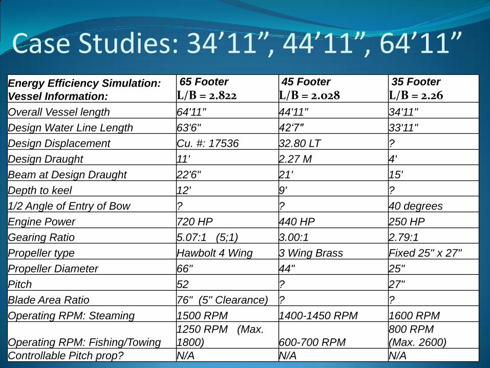
Case Studies: 34’11”, 44’11”, 64’11”Energy Efficiency Simulation:
Vessel Information:
65 Footer
L/B = 2.82245 Footer
L/B = 2.02835 Footer
L/B = 2.26
Overall Vessel length 64'11" 44'11" 34'11"
Design Water Line Length 63'6" 42‘7" 33'11"
Design Displacement Cu. #: 17536 32.80 LT ?
Design Draught 11' 2.27 M 4'
Beam at Design Draught 22'6" 21' 15'
Depth to keel 12' 9' ?
1/2 Angle of Entry of Bow ? ? 40 degrees
Engine Power 720 HP 440 HP 250 HP
Gearing Ratio 5.07:1 (5;1) 3.00:1 2.79:1
Propeller type Hawbolt 4 Wing 3 Wing Brass Fixed 25" x 27"
Propeller Diameter 66" 44" 25"
Pitch 52 ? 27"
Blade Area Ratio 76" (5" Clearance) ? ?
Operating RPM: Steaming 1500 RPM 1400-1450 RPM 1600 RPM
Operating RPM: Fishing/Towing
1250 RPM (Max.
1800) 600-700 RPM
800 RPM
(Max. 2600)
Controllable Pitch prop? N/A N/A N/A

11
Case Studies: Simulations & Analysis Appendage Drag: Best and Worst Case
Hull Surface Fouling: Drag Clean vs. Fouled
Effect of ½ Angle of Entry : varied from 110% of As-Built to 70% As-Built Change in Displacement with bow ½ Angle
All other parameters constant
Effect of Immersed Transom: Varied as 100% of Midship Draught to 10% of Midship Draught (A box to a Wedge!) Change in Displacement with transom draught
All other Parameters Constant
Estimated Power Requirements in a Seaway: Calm to SS6
Estimated Powerw in a Seaway for Ideal Hull:
10% of Midship Draught Transom Immersion
70% of As-Built ½ Angle
Overall increase in length by 5 ft or 10ft for the 65’
Lengthened Skeg to achieve greater propeller clearance
Change in Displacement with length increase
Propeller Simulations: (Overall Propulsive & Required Engine RPM & Power)
As-Built Efficiency
Optimised Propeller, As-Built Hull, Efficiency:
Idealised Hull and Propeller

12
•Generate Test Series & Design Envelope
•Three bulbous bows designed & Tested in:Seakeeping (Zero speed)
Resistance
Self-Propulsion
•Vessel Lengths Tested to date:45’
65’
110’
100
90’
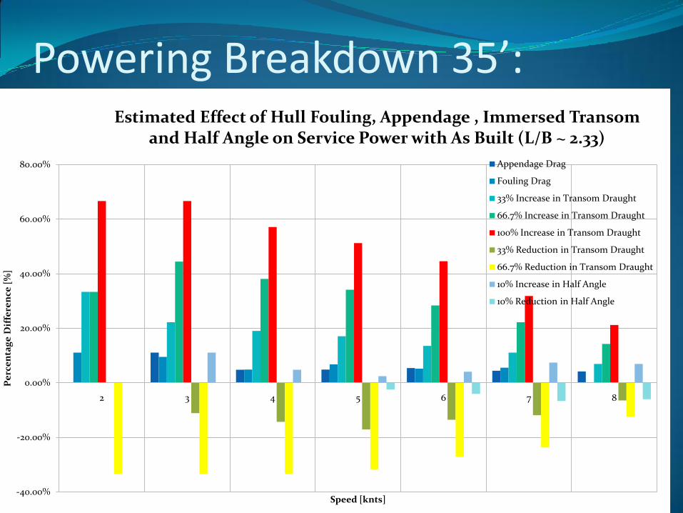
Powering Breakdown 35’:
-40.00%
-20.00%
0.00%
20.00%
40.00%
60.00%
80.00%
2 3 4 5 6 7 8
Pe
rce
nta
ge
Dif
fere
nce
[%
]
Speed [knts]
Estimated Effect of Hull Fouling, Appendage , Immersed Transom and Half Angle on Service Power with As Built (L/B ~ 2.33)
Appendage Drag
Fouling Drag
33% Increase in Transom Draught
66.7% Increase in Transom Draught
100% Increase in Transom Draught
33% Reduction in Transom Draught
66.7% Reduction in Transom Draught
10% Increase in Half Angle
10% Reduction in Half Angle

Simulated ‘Idealised’ Vessel:
Lengthened Bow – Finer & Gradual Shape
Reduced Shoulder - Reduced Flow Separation
Lengthened Bow – Finer & Gradual Shape
15
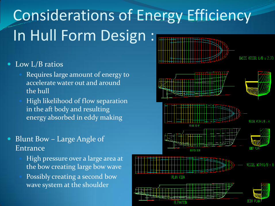
Considerations of Energy Efficiency In Hull Form Design :
Low L/B ratios
Requires large amount of energy to accelerate water out and around the hull
High likelihood of flow separation in the aft body and resulting energy absorbed in eddy making
Blunt Bow – Large Angle of Entrance
High pressure over a large area at the bow creating large bow wave
Possibly creating a second bow wave system at the shoulder

EFFECT OF BOW & L/B RATIO ON RESULTANT WAVE SYSTEM L/B = 4.074 (Bulb A) L/B =2.407 (Standard Bow)
L/B 2.4

17
The Influence of Vessel Length on Seakeeping:
• Investigated Seakeepingperformance and Influence on the number of days available for fishing.
• Seakeeping done on all bows for 90’ at ahead, ahead quartering, beam and stern seas.
• One Test Included a basically modelled anti-roll tankVessel
Length
Critical Wave
Height
Threshold,
MII/minute
65 feet 3.0 m 0.955
85 feet 3.75 m 1.06
90 feet 4.0 m 0.992
110 feet 4.25 m 0.856
150 feet 5.0 m 1.08
Critical Wave Height
y = -0.0002x2 + 0.059x - 0.0718
R2 = 0.983
0
1
2
3
4
5
6
0 20 40 60 80 100 120 140 160
Vessel length in feet
Cri
tical W
ave H
eig
ht
in m
etr
es
Critical Wave Height (m)
Poly. (Critical Wave Height
(m))

The influence of Vessel Length on Fuel Consumption:
Investigated Energy Efficiency as a function of vessel length
Estimated the Fuel Consumption per Pound of Catch over a variety of Lengths
% fuel rate per lb
0.00%
20.00%
40.00%
60.00%
80.00%
100.00%
120.00%
0 20 40 60 80 100 120 140 160
Vessel length in ft
fue
l c
on
su
mp
tio
n r
ate
re
lati
ve
to
65
' v
es
se
l
% fuel rate per lb

Influence of Vessel Beam on Fuel Consumption:
10 knots
Pservice
Difference
B/L Beam (ft) Pservice (kW) % Relative to 27'
0.278 25 486.46 -9.02%
0.300 27 534.68 0.00%
0.311 28 557.52 4.27%
0.322 29 581.41 8.74%
0.333 30 605.79 13.30%
0.356 32 654.43 22.40%
0.378 34 702.95 31.47%
0.400 36 752.50 40.74%
0.422 38 802.34 50.06%
0.444 40 852.87 59.51%
Difference
Relative to 27’
B/L Beam L/24hrs litres/24hrs
0.278 25 600.00 -48.0000
0.300 27 648.00 0.0000
0.311 28 672.00 24.0000
0.322 29 696.00 48.0000
0.333 30 720.00 72.0000
0.356 32 768.00 120.0000
0.378 34 816.00 168.0000
0.400 36 864.00 216.0000
0.422 38 912.00 264.0000
0.444 40 960.00 312.0000

20
The Effect of Stern Shape and Immersed Transom on Design:
Submerged Transom Creates a very low pressure at the stern resulting in
a large mass of water being dragged along with the boat
Poor flow of water to the propeller Resulting from flow separation due to the high rate
of change in stern lines
Further aggravated by the presence of a large amount of submerged transom area
Stern Rise = Low Transom immersion
High Prop Clearance
NO Stern Rise = High
Transom immersion =
Inefficient

Overview of Considerations:
0
50
100
150
200
250
300
350
400
450
0 1 2 3 4 5 6 7 8 9
Se
rvic
e P
ow
er
[kW
]
Speed [knts]
Comparison of Estimated Service Power in a Seaway for an As-Built 35' (L/B = 2.33) with an Optimised & Lengthened 39‘11”
Version (L/B = 2.66)
As-Built Calm
As-Built ss4
As-Built ss5
Modified Calm
Modified ss4
Modified ss5

Overview of Considerations:
0
500
1000
1500
2000
2500
3000
3500
4000
4500
1 3 5 7 9 11 13
Se
rvic
e P
ow
er
[kW
]
Speed [knts]
Comparison of Estimated Service Power Required in a Seaway for an As-Built 65' (L/B = 2.89) with an Optimised & Lengthened
74‘11” Version (L/B = 3.33)
As-Built Calm
As-Built ss4
As-Built ss5
As-Built SS6
Modified Calm
Modified ss4
Modified ss5
Modified ss6

Potential Design Aids/Tools: Tank Testing & Simulation:

Design Predictions – What it Can Do:
Tank Testing, Simulations & Data Analysis :
• Performance & Powering
• Propeller, Gearing and Powering Design Envelopes
• Dynamic Stability
• Induced Motions/Seaworthiness
• Effects of Appendages and Bulbous bows
• Effect of Roll Dampening Devices

Testing Example: Effect Of Speed On Wave System & Powering
Standard Bow~ 8.5 Knots Full Scale Equivalent (L/B = 2.407)
Standard Bow~ 10.5 Knots Full Scale Equivalent (L/B = 2.407)
VIDEO 8.5 VIDEO 10.5

Design Tools: FUEL RATE COMPARISON:
0
500
1000
1500
2000
2500
3000
3500
4000
0 500 1000 1500 2000 2500 3000
To
tal
Fu
el
Co
nsu
me
d [
l]
Engine RPM
Fuel Consumption Over 100 Nautical Miles with Hull and Prop Variation (Maximum RPM ~ 12 Knots Speed)
As Built Prop
Optimised Prop
Ideal Hull Prop

EX :Reasonable Vessel Parameters 75’ x 22’:Fewer Decks – Less Windage & Iceing Surface
~ Lower Centre of Gravity

Material Considerations: Fibreglass:
Weight Savings
Moulded Design Facilitates:
Clean, Fair Surface Finish
Great variation in Possible Geometric Shapes
Chemically Inert (doesn’t rust!)
Potential Cost savings for smaller vessels and series builds
Caution: Cost of Resins can vary with cost of Fuel
Can have water ingress and de-lamination/blistering issues
Steel: Strong and Durable (Large margin of safety especially against impact)
Easier to repair large structural damage
Can build Any size, not mould dependent
Chemically Sensitive Corrosion
Higher maintenance costs

It may challenge some of our pre-conceptions of how an efficient, safe, reliable and economically viable vessel looks:
Expect:
Research of Alternative Equipment, Materials, Fuel Systems and Machinery and Associated Economic Costs& Payback Periods
Clear Documentation on Vessel Trim and Stability (DFO & Transport Canada Requirements/Regulations)
Comprehensive Design Drawings and Documentation
Vessel Incline Tests
Sea Trials
Documentation of As-Built Vessel Performance
What Proper Vessel Design Can Provide:

Proportional Vessel Parameters (Closer to our Ideal):
•High L/B Ratio
•Gradual Changes
in Hull Shape
•Fine Bow = Low
Half Angle of
Entrance
•Stern Rise
•Needs to be
Cleaned and Faired

•Length to Beam is very significant (Higher L/B more efficient)
•Increased Length overall is more efficient
•Lowest Transom Immersion as possible
•Smallest Bow Half Angle Possible without creating an unnecessary abrupt change at the Shoulder
•Stern tube and Submerged Stern Shape should maximise space for Propeller (ensuring min. Clearance) & Ensure Clean Flow
•Propellers should be optimised for cruising (in most cases) in at the most efficient speed and engine RPM while ensuring sufficient Bollard Pull
•Lower Superstructure for reduced Windage and Iceing Areas
•Fewer Above water Decks = lower centre of gravity (NO NEED for permanent Ballast in proper design only Ballast Tanks )

•CPP, different Nozzles, alternate Rudders, etc. Should be considered
•Properly Designed Bulbs are very useful at minimising required Power (and hence RPM) at Intended Design speed
•Properly Designed bulbs reduce motions in a seaway
•Properly Designed and Tuned Anti-Roll tanks are the most cost effective at reducing roll motions in a range of sea states
•Fuel Efficient Engines and Monitoring Systems
•Modular Gear Installation for Easy conversion to different Species
•Material Selection: Fibreglass vs. Steel
•AS GRADUAL CHANGES IN HULL SHAPE AS POSSIBLE! Fine Bow and Faired, Rising Stern!

CONCLUDING SLIDE