new variants to theoretical investigations of …cdn.intechweb.org/pdfs/20825.pdfnew variants to...
TRANSCRIPT

16
New Variants to Theoretical Investigations of Thermosyphon Loop
Henryk Bieliński The Szewalski Institute of Fluid-Flow Machinery, Polish Academy of Sciences, Gdańsk
Poland
1. Introduction
The purpose of this chapter is to present three variants of the generalized model of thermosyphon loop, using a detailed analysis of heat transfer and fluid flow (Bieliński & Mikielewicz, 2011). This theoretical investigation of thermosyphon loop is based on analytical and numerical calculations. The first variant of thermosyphon loop (HHVCHV) is composed of two heated sides: the lower horizontal and vertical sides and two cooled sides: the upper horizontal and vertical opposite sides. This variant is made for conventional tubes and has a one-phase fluid as the working substance. The second variant of thermosyphon loop (2H2C) is consisted of two lower evaporators: horizontal and vertical and two upper condensers: horizontal and vertical and is made for minichannels. The third variant of thermosyphon loop has an evaporator on the lower horizontal section and a condenser on the upper vertical section. This variant contains minichannels and a supporting minipump (HHCV+P). A two-phase fluid is used as the working substance in the second and third variants. The new variants reported in the present study is a continuation and an extension of earlier work “Natural Circulation in Single and Two Phase Thermosyphon Loop with Conventional Tubes and Minichannels.” published by InTech (ISBN 978-953-307-550-1) in book “Heat Transfer. Mathematical Modelling, Numerical Methods and Information Technology”, Edited by A. Belmiloudi, pp. 475-496, (2011). This previous work starts a discussion of the generalized model for the thermosyphon loop and describes three variants. In the first variant (HHCH) the lower horizontal side of the thermosyphon loop was heated and its upper horizontal side was cooled. In the second variant (HVCV) the lower part of vertical side of the thermosyphon loop was heated and its upper part at opposite vertical side was cooled. In the third variant (HHCV) a section of the lower horizontal side of the thermosyphon loop was heated and its upper section of vertical side was cooled. A one- and two-phase fluid were used as a working substance in the first and in both second and third variants of the thermosyphon loop, respectively. Additionally, the first variant was made for conventional tubes and the second and third variants were made for minichannels. It was necessary in case of the thermosyphon loop with minichannels to apply some new correlations for the void fraction and the local two-phase friction coefficient in both two-phase regions: adiabatic and diabatic, and the local heat transfer coefficient in flow boiling and condensation. Some other variants to theoretical investigations of the generalized model for thermosyphon loop are demonstrated in (Bieliński & Mikielewicz, 2004, 2005, 2010).
www.intechopen.com

Two Phase Flow, Phase Change and Numerical Modeling
366
Fluid flow of thermosyphon loop is created by the buoyancy forces that evolve from the density gradients induced by temperature differences in the heating and cooling sections of the loop. An advanced thermosyphon loop is composed of an evaporator and a condenser; a riser and a downcomer connect these parts. A liquid boils into its vapour phase in the evaporator and the vapour condenses back to a liquid in the condenser. The thermosyphon loop is a simple passive heat transfer device, which relies on gravity for returning the liquid to the evaporator. The thermosyphon loops are a far better solution than other cooling systems because they are pumpless. In such cases, when mass flow rate is not high enough to circulate the necessary fluid to transport heat from evaporator to condenser, the use of a pump is necessary. The presented study considers the case where the buoyancy term and the pump term in the momentum equation are of the same order. The following applications for thermosyphon loops are well-known, such as solar water heaters, thermosyphon reboilers, geothermal systems, emergency cooling systems in nuclear reactor cores, thermal diodes and electronic device cooling. The thermal diode is based on natural circulation of the fluid around the closed-loop thermosyphon (Bieliński & Mikielewicz, 1995, 2001), (Chen, 1998). The closed-loop thermosyphon is also known as a “liquid fin” (Madejski & Mikielewicz, 1971). Numerous investigations, both theoretical and experimental have been conducted to study of the fluid behaviour in thermosyphon loops. Zvirin (Zvirin, 1981) presented results of theoretical and experimental studies concerned with natural circulation loops, and modelling methods describing steady state flows, transient and stability characteristics. Ramos (Ramos et al., 1985) performed the theoretical study of the steady state flow in the two-phase thermosyphon loop with conventional tube. Greif (Greif, 1988) reviewed basic experimental and theoretical work on natural circulation loops. Vijayan (Vijayan et al., 2005) compared the dynamic behaviour of the single- and two-phase thermosyphon loop with conventional tube and the different displacement of heater and cooler. Misale (Misale et al., 2007) reports an experimental investigations related to rectangular single-phase natural circulation mini-loop. The present study provides in-depth analysis of heat transfer and fluid flow using three new variants of the generalized model of thermosyphon loop. Each individual variant can be analyzed in terms of single- and two-phase flow in the thermosyphon loop with conventional tubes and minichannels. In order to analyse the numerical results of simulation for the two-phase flow and heat transfer in the thermosyphon loop, the empirical correlations for the heat transfer coefficient in flow boiling and condensation, and two-phase friction factor in diabatic and adiabatic sectors in minichannels, are used. The analysis of the thermosyphon loop is based on the one-dimensional model, which includes mass, momentum and energy balances. The separate two-phase flow model is used in calculations. A numerical investigation for the analysis of the mass flux and heat transfer coefficient in the steady state has been done. The effect of thermal and geometrical parameters of the loop on the mass flux in the steady state is examined numerically. The El-Hajal correlation for void fraction (El-Hajal et al., 2003), the Zhang-Webb correlation for the friction pressure drop of two-phase flow in adiabatic region (Zhang & Webb, 2001), the Tran correlation for the friction pressure drop of two-phase flow in diabatic region (Tran et al. 2000), the Mikielewicz (Mikielewicz et al., 2007) and the Saitoh (Saitoh et al., 2007) correlations for the flow boiling heat transfer coefficient in minichannels, the Mikielewicz (Mikielewicz et al., 2007) and the Tang (Tang et al., 2000) correlations for condensation heat transfer coefficient in minichannels has been used to evaluate the thermosyphon loop with minichannels.
www.intechopen.com
New Variants to Theoretical Investigations of Thermosyphon Loop
367
Finally, theoretical investigations of the variants associated with the generalized model of thermosyphon loop can offer practical advice for technical and research purposes.
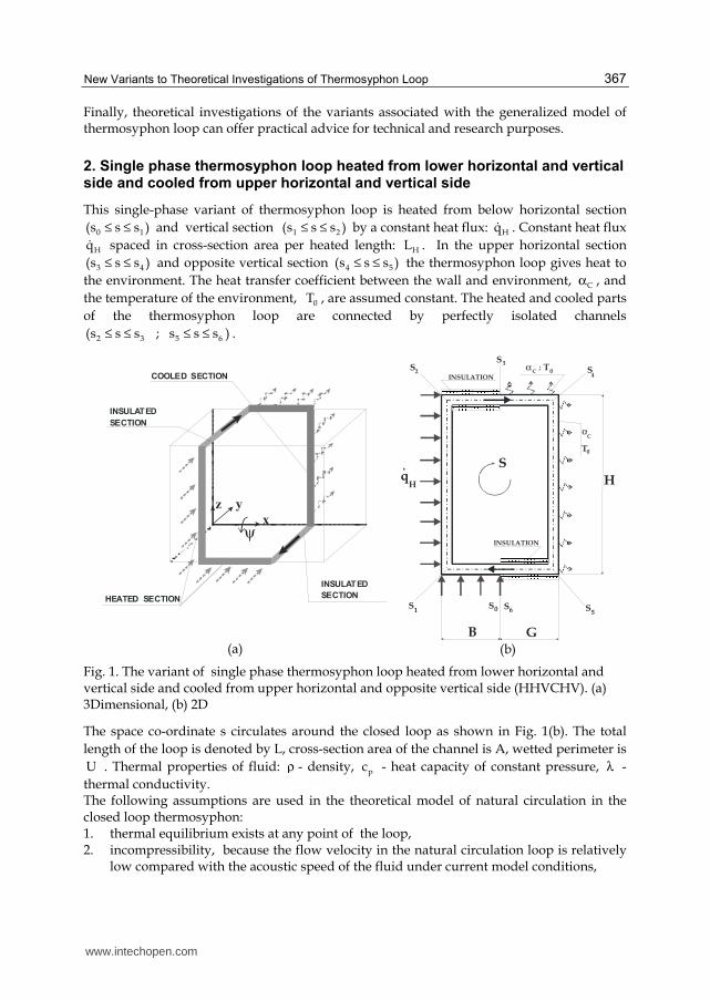
2. Single phase thermosyphon loop heated from lower horizontal and vertical side and cooled from upper horizontal and vertical side
This single-phase variant of thermosyphon loop is heated from below horizontal section
0 1(s s s )≤ ≤ and vertical section 1 2(s s s )≤ ≤ by a constant heat flux: Hq . Constant heat flux
Hq spaced in cross-section area per heated length: HL . In the upper horizontal section
3 4(s s s )≤ ≤ and opposite vertical section 4 5(s s s )≤ ≤ the thermosyphon loop gives heat to
the environment. The heat transfer coefficient between the wall and environment, Cα , and
the temperature of the environment, 0T , are assumed constant. The heated and cooled parts
of the thermosyphon loop are connected by perfectly isolated channels
2 3 5 6(s s s ; s s s )≤ ≤ ≤ ≤ .
HEATED SECTION
INSULATED
COOLED SECTION
z y
x
SECTION
INSULATED
SECTION
ψ
(a)
INSULATION
INSULATION
H
S
α
α
C
C
T
T
0
0;
GB
SS
q
SS
S
H
2
3
4
01 6 5S S
(b)
Fig. 1. The variant of single phase thermosyphon loop heated from lower horizontal and vertical side and cooled from upper horizontal and opposite vertical side (HHVCHV). (a) 3Dimensional, (b) 2D
The space co-ordinate s circulates around the closed loop as shown in Fig. 1(b). The total
length of the loop is denoted by L, cross-section area of the channel is A, wetted perimeter is
U . Thermal properties of fluid: ρ - density, pc - heat capacity of constant pressure, λ -
thermal conductivity. The following assumptions are used in the theoretical model of natural circulation in the closed loop thermosyphon: 1. thermal equilibrium exists at any point of the loop, 2. incompressibility, because the flow velocity in the natural circulation loop is relatively
low compared with the acoustic speed of the fluid under current model conditions,
www.intechopen.com

Two Phase Flow, Phase Change and Numerical Modeling
368
3. viscous dissipation in fluid is neglected in the energy equations, 4. heat losses in the thermosyphon loop are negligible,
5. ( )D L 1 ;<< one-dimensional models are used and the flow is fully mixed. The velocity
and temperature variation at any cross section is therefore neglected. The flow is fully
developed and the temperature is uniform at the steady state, 6. single-phase fluid can be selected as the working fluid, 7. curvature effects and associated form losses are negligible, 8. fluid properties are constants, except density in the gravity term. The Boussinsq
approximation is valid for a single-phase system, then density is assumed to vary as
( )0 01 T Tρ = ρ ⋅ − β ⋅ − in the gravity term where p0
1
T
∂υ β = ⋅ υ ∂ ( υ - specific volume,
“0” is the reference of steady state), 9. the effect of superheating and subcooling are neglected. Under the above assumptions, the governing equations for natural circulation systems can be written as follows: - conservation of mass:
( )w 0 ;s
∂ρ ∂+ ρ ⋅ =
∂τ ∂ (1)
where τ - time, w - velocity.
- conservation of momentum:
w
w w p Uw g ;
s s A
∂ ∂ ∂ ρ ⋅ + ⋅ = − + ε ⋅ρ ⋅ − τ ⋅ ∂τ ∂ ∂ (2)
where ( ) ( )0 for e g ; 1 for e g ; 1 for e g ;ε = ⊥ ε = + ↑ ∧ ↓ ε = − ↓ ∧ ↓
g e g 1 g cos(e,g);= = ⋅ ⋅
g g; e 1= =
; e
is a versor of the coordinate around the loop, and wτ - wall shear
stress. - conservation of energy:
0
0
2C C
0 2p 0
H H
p 0
0 for adiabatic section
T T T q Uw a for cooled section
s s c A
q Ufor heated section
c A
+∂ ∂ ∂ ⋅
+ ⋅ = ⋅ −∂τ ∂ ∂ ⋅ρ ⋅
⋅+ ⋅ ρ ⋅
(3)
where 0
00
0 p
ac
λ=
ρ ⋅ - thermal diffusivity,
In order to eliminate the pressure gradient and the acceleration term, the momentum
equation in Eq. (2) is integrated around the loop p
ds 0s
∂ = ∂ .
www.intechopen.com

New Variants to Theoretical Investigations of Thermosyphon Loop
369
The flow in natural circulation systems which is driven by density distribution is also known as a gravity driven flow or thermosyphonic flow. The momentum and the energy equations in such flows are coupled and for this reason they must be solved simultaneously (Mikielewicz, 1995). The above governing equations can be transformed to their dimensionless forms by the following scaling:
2 0 H 00 0 0 2
H
(A /U ) (T T )(a ) /L ; s s /L ; m (m L) (a A) ; T ;
(q L )+ + + + λ ⋅ ⋅ −
τ = ⋅ τ = = ⋅ ⋅ρ ⋅ =⋅
(4)
The dimensionless momentum equation and the energy equation at the steady state for the thermosyphon loop heated from below can be written as follows:
- momentum equation (with: j jK s L ;= ) and 1 for lamin ar flow
7 4 for turbulent flow
θ = ;
( ) ( ) ( )1
**
0
m (Ra) 1 T cos e,g ds ;θ+ + +
= − ⋅ ⋅ (5)
- energy equation
2
**
2
0 insulated sections
dT d Tm (Bi) T for cooling section
ds ds
1 heater sec tion
+ ++ +
+ +
+= − ⋅ +
(6)
with boundary conditions
2 2 3 3
5 5
A1 2 H 2 A1 3 C 3 C 5 A2 5 A2 H
A1 H A1 C
s K s K s K s K
C A2 A2 H
s K s K s 1 s 0
T ( K ) T ( K ) ; T (K ) T (K ) ; T (K ) T (K ) ; T (1) T (0) ;
dT dT dT dT; ;
ds ds ds ds
dT dT dT dT; ;
ds ds ds ds
+ + + +
+ + + +
+ + + + + + + +
+ + + +
+ + + += = = =
+ + + +
+ + + += = = =
= = = =
= =
= =
(7)
The parameters appearing in the momentum and the energy equations are the modified Biot, Rayleigh and Prandtl numbers.
2
** C C
0
U L(Bi) ;
A
α ⋅= ⋅
λ (8)
for laminar flow: ( )1θ =
23
** ** 20 H 0 H 0l l2
0 0 0
g L (q / ) A U U(Ra) ; (Pr) 2 L ;
a 2 U A a
⋅β ⋅ ⋅ λ ⋅ ν = ⋅ = ⋅ ⋅ ⋅ ν ⋅ ⋅
(9)
www.intechopen.com

Two Phase Flow, Phase Change and Numerical Modeling
370
for turbulent flow: ( )7 4θ =
( )
( ) ( )( )
( )
1 415 4 1 4 5 4
0 H 0 H** ** 0t t1 4 7 4 5 4
00 0
g L (q / ) A U128 0.3164 L U(Ra) ; (Pr) ;
0.3164 A a128a U
⋅β ⋅ ⋅ λ ⋅ ⋅ ν = ⋅ ⋅ = ⋅ ⋅ ν ⋅
(10)
In the case of the laminar and turbulent steady-state flow, the dimensionless distributions of temperature around the loop can be obtained analytically from Eq. (6). The distilled water was used as the working fluid. It has been found that the Biot number has an influence on temperature in the laminar and turbulent flow. The results are shown in Figs. 2 and 3.
0,0 0,2 0,4 0,6 0,8 1,0
00
5x10⁻⁵
5x10⁻⁵
1x10⁻⁴
1x10⁻⁴
T+
A1
T+
A2
T+
C
T+
H
(Bi)**
= 5*105
(Bi)**
=1*104
DIM
EN
SIO
NL
ES
S
TE
MP
ER
AT
UR
E
T +
DIMENSIONLESS COORDINATE s +
Fig. 2. The effect of Biot number on temperatures in the laminar steady-state flow (HHVCHV)
0,0 0,2 0,4 0,6 0,8 1,0
1,98x10⁻⁶
2,00x10⁻⁶
1,00x10⁻⁴
T+
A1
T+
A2
T+
C
T+
H
(Bi)**
= 5*105
(Bi)**=1*10
4
DIM
EN
SIO
NL
ES
S
TE
MP
ER
AT
UR
E
T+
DIMENSIONLESS COORDINATE s +
Fig. 3. The effect of Biot number on temperatures in the turbulent steady-state flow (HHVCHV)
www.intechopen.com

New Variants to Theoretical Investigations of Thermosyphon Loop
371
The effect of the loop’s aspect ratio (breadth B to height H) on the mass flow rate found numerically in the case of laminar flow at the steady state is presented in Fig. 4 .
0 4x10⁹
8x10⁹
0
4x10³
8x10³
B/H = 1*10-3
B/H = 1*10-2
B/H = 1,1
B/H = 1*102
B/H = 1*103
MA
SS
FL
OW
RA
TE
m
l+
MODIFIED RAYLEIGH NUMBER (Ra)l
**
Fig. 4. Mass flow rate for laminar flow at the steady state versus modified Rayleigh number at different B/H ratios (HHVCHV)
For this variant of the thermosyphon loop it has been found that the maximum of the mass flow rate appears for B/H=1,1 . The effect of geometrical parameter of the loop (length of insulation section G to height H) on the mass flow rate found numerically in the case of laminar flow at the steady state is presented in Fig. 5. The mass flow rate increases with decreasing G/H aspect ratio, due to the decreasing frictional pressure term.
1x10⁶
1x10⁸
1x10¹⁰
1x10¹²
1x10¹⁴
1x10²
1x10³
1x10⁴
G/H = 0,001
G/H = 1
G/H = 1000
MA
SS
FL
OW
RA
TE
m
l+
MODIFIED RAYLEIGH NUMBER (Ra)l
**
Fig. 5. Mass flow rate for laminar flow at the steady state versus modified Rayleigh number at different G/H ratios (HHVCHV)
www.intechopen.com

Two Phase Flow, Phase Change and Numerical Modeling
372
This paper presents the case of the onset of motion of the single-phase fluid from a rest state
if the loop rotates 90 degrees around the x-axis. The heated sections can be presented in the
horizontal plane below the cooled sections. The presented numerical calculations are based
on a new method for solution of the problem for the onset of motion in the fluid from the
rest (Bieliński & Mikielewicz, 2005). Conditions for the onset of motion in the thermosyphon
can be determined by considering the steady solutions with circulation for the limiting case
of lm 0+ → .
0 1x10³
2x10³
3x10³
00
22
44
66
ψ = 0o
ψ = 60o
ψ = 90o
MA
SS
FL
OW
RA
TE
m
l +
MODIFIED RAYLEIGH NUMBER (Ra)l
**
Fig. 6. The case of the onset of motion of the single-phase fluid from a rest state if the loop
rotates 90 degrees around the x-axis (HHVCHV+ o90ψ )
The analysis was based on the equations of motion and energy for the steady-state
conditions. The heat conduction term has to be taken into account in this approach because
the heat transfer due to conduction is becoming an increasingly important factor for
decreasing mass flow rates. The fluid starts circulation around the loop, when the Rayleigh
number exceeds a critical value, which can be found using the method lm 0+ → for the o90ψ = angle. The critical Rayleigh number for angles o90ψ < is zero. This means that the
circulation of the fluid around the loop begins after the start up of the heating (Fig. 6).
3. Two-phase thermosyphon loop with heated from lower horizontal and vertical parts and cooled from upper horizontal and vertical parts
The variant of the two-phase closed thermosyphon loop consists of two heaters and two
coolers connected by channels. A schematic diagram of a one-dimensional model of the
thermosyphon loop is shown in Fig. 7. The thermosyphon loop is heated from lower
horizontal section 0 1(s s s )≤ ≤ and lower vertical section 3 4(s s s )≤ ≤ by a constant heat flux:
H1q and H2q , respectively and cooled in the upper horizontal section 6 7(s s s )≤ ≤ and
upper vertical section 9 10(s s s )≤ ≤ by a constant heat flux: C1q and C2q , respectively.
www.intechopen.com

New Variants to Theoretical Investigations of Thermosyphon Loop
373
4
C2
C1
L
L
C2
H2
65
1
7
2
3
L
L
L
L
L
8
10
0
9
1112H1
H2
S
S
SS S
S
S
S
SSSS
0H2
0H1
H1
0C1
C1
0C2L
Fig. 7. A schematic diagram of a one-dimensional model of the thermosyphon loop (2H2C)
The constant heat fluxes H1q , H2q and C1q , C2q are applied in the cross-section area per
heated and cooled length: H1L , H2L and C1L , C2L ,respectively. The heated and cooled parts
of the thermosyphon loop are connected by perfectly insulated channels
1 3(s s s )≤ ≤ , 4 6(s s s )≤ ≤ , 7 9(s s s )≤ ≤ , 10 12(s s s )≤ ≤ .
The coordinate s along the loop and the characteristic geometrical points on the loop are
marked with sj , as shown in Fig. 7. The total length of the loop is denoted by L, the cross-
section area of the channel by A and the wetted perimeter by U . Thermal properties of
fluid: ρ - density, pc - heat capacity of constant pressure, λ - thermal conductivity. The following additional assumptions are made in this study: 1. heat exchangers in the thermosyphon loop can be equipped by minichannels, 2. two-phase fluid can be selected as the working fluid,
3. friction coefficient is constant in each region of the loop, separate two-phase flow model
can be used in calculations for the frictional pressure loss in the heated, cooled and
adiabatic two-phase sections; the two-phase friction factor multiplier 2L0R = φ is used;
the density in the gravity term can be approximated as follows: ( )V L1ρ = α ⋅ρ + − α ⋅ρ ,
where α is a void fraction, 4. quality of vapour in the two-phase regions is assumed to be a linear function of the
coordinate around the loop, 5. effect of superheating and subcooling are neglected. In order to eliminate the pressure gradient and the acceleration term, the momentum
equation in Eq. (2) is integrated around the loop p
ds 0s
∂ = ∂ .
After integrating the gravitational term in the momentum equation (2) around the loop, we obtain
www.intechopen.com

Two Phase Flow, Phase Change and Numerical Modeling
374
{ } ( ) ( ) ( ) ( ){
( ) ( ) }1 3 3 4 4 6
7 9 9 10
V L 3 2 4 3 5 4s ;s s ;s s ;s
9 8 10 9s ;s s ;s
g ds g s s s s s s
s s s s 0 ;
ε ⋅ ⋅ ρ = ⋅ ρ − ρ ⋅ − ⋅ α + − ⋅ α + − ⋅ α +
− − ⋅ α − − ⋅ α =
(11)
where ( )
( )K
P K P K
P
s
s ;s s ;sK P s
1s ds
s sα = ⋅ α
− .
Due to the friction of fluid, the pressure losses in two-phase regions can be calculated as
w
2p L0
U dp dpR
A ds ds
− − ⋅ τ = = ⋅ (12)
where: ( )2
ChurL0
L0 L
2 f Gdp
ds D
⋅ ⋅ = ⋅ ρ
is the liquid only frictional pressure gradient calculated for
the total liquid mass velocity, G w= ρ ⋅ , ChurL0f is friction factor of the fluid (Churchill, 1977).
After integrating the friction term in Eq. (2) around the loop, the solution is obtained as follows
( ) ( ) ( ){
( ) ( ) ( ) ( ) ( )}0 1 1 3 3 4
4 6 6 7 7 9 9 10
w 1 0 3 1 4 3s ;s s ;s s ;sL0
6 4 7 6 9 7 10 9 12 10s ;s s ;s s ;s s ;s
U dpds s s R s s R s s R
A ds
s s R s s R s s R s s R s s ;
⋅ τ = ⋅ − ⋅ + − ⋅ + − ⋅ + + − ⋅ + − ⋅ + − ⋅ + − ⋅ + −
(13)
3.1 Minichannels. Distribution of the mass flux
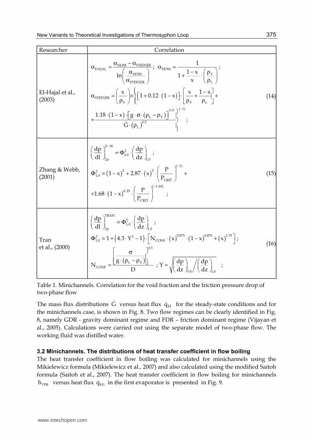
The following correlations have been used in calculation of the thermosyphon loop with minichannels (Table 1): the El-Hajal correlation for void fraction (El-Hajal et al., 2003), the Zhang-Webb correlation for the friction pressure drop of two-phase flow in adiabatic region (Zhang & Webb, 2001), the Tran correlation for the friction pressure drop of two-phase flow in diabatic region (Tran et al. 2000).
Fig. 8. Minichannels. Mass flux G as a function of Hq for the steady state (2H2C), (L=0.2
[m], D=0.002 [m], H=0.07 [m], B=0.03 [m], LH1= LH2=LC1= LC2=0.02 [m],
LH1P= LH2P =LC1P= LC2P =0.005 [m] )
www.intechopen.com
New Variants to Theoretical Investigations of Thermosyphon Loop
375
Researcher Correlation
El-Hajal et al., (2003)
HOM STEINERHAJAL HOM
VHOM
LSTEINER
1; ;
1 x1ln
x
α − αα = α = − ρα
+ ⋅ ρα
( )
( ) ( )( )
0.25
STEINER
V V L
( 1)
L V
0.5
L
x x 1 x1 0.12 1 x
1.18 1 x g;
G
−
−α = × + ⋅ − ⋅ + + ρ ρ ρ
⋅ − ⋅ ⋅ σ ⋅ ρ − ρ + ⋅ ρ
(14)
Zhang & Webb, (2001)
( ) ( )( )
( )( )
Z W
2L0
2p L0
1
2 22L0
CRIT
1.64
0.25
CRIT
dp dp;
dl dz
P1 x 2.87 x
P
P1.68 1 x ;
P
−
−
−
= Φ ⋅
Φ = − + ⋅ ⋅ +
+ ⋅ − ⋅
(15)
Tran et al., (2000)
( ) ( ) ( ) ( )
( )
TRAN
2L0
2p L0
0.875 0.875 1.752 2L0 CONF
0.5
L V
CONFV0 L0
dp dp;
dl dz
1 4.3 Y 1 N x 1 x x ;
g dp dpN ; Y ;
dz dzD
= Φ ⋅ Φ = + ⋅ − ⋅ ⋅ ⋅ − +
σ ⋅ ρ − ρ = =
(16)
Table 1. Minichannels. Correlation for the void fraction and the friction pressure drop of two-phase flow
The mass flux distributions G versus heat flux Hq for the steady-state conditions and for
the minichannels case, is shown in Fig. 8. Two flow regimes can be clearly identified in Fig.
8, namely GDR - gravity dominant regime and FDR – friction dominant regime (Vijayan et
al., 2005). Calculations were carried out using the separate model of two-phase flow. The
working fluid was distilled water.
3.2 Minichannels. The distributions of heat transfer coefficient in flow boiling
The heat transfer coefficient in flow boiling was calculated for minichannels using the
Mikielewicz formula (Mikielewicz et al., 2007) and also calculated using the modified Saitoh
formula (Saitoh et al., 2007). The heat transfer coefficient in flow boiling for minichannels
TPBh versus heat flux H1q in the first evaporator is presented in Fig. 9.
www.intechopen.com

Two Phase Flow, Phase Change and Numerical Modeling
376
Researcher Correlation
Mikielewicz et al., (2007)
( )2JM
nTPB PB
M S
REF REF
h 1 hR ;
h 1 P h−
= + ⋅
+
( )( ) ( )1
1 33
M S CONF
1 1z
1 1R 1 2 1 x N 1 x x ;
f f
−−
= + ⋅ − ⋅ ⋅ ⋅ − + ⋅
LAM LAM LAML L V LREF 1 1z
V L V
LAM n 2 ; 4.36 ; f ; f ;D
λ µ ρ λ = α = ⋅ = ⋅ = µ ρ λ ( ) ( )
10.8L 3
REF L0 L
1 370.25
3 215pLTUR TURL V V L
1 1z
V L L pV V
TUR n 0.76 ; h 0.023 Re Pr ;D
cf ; f ;
c
λ = = ⋅ ⋅ ⋅
µ ρ µ λ= ⋅ = ⋅ ⋅ µ ρ µ λ
( ) ( ) ( ) ( )( ) ( ) ( )1.17 0.6 0.653L0 M S L0
L
q G dP 2.53 10 Re Bo R 1 ; Bo ; Re ;
G r
−−−
⋅= × ⋅ ⋅ ⋅ − = =
µ⋅
( )( )0.550.12
0.50.67 n nPB 10
CRIT CRIT
P Ph 55 q M log ;
P P
−
− = ⋅ ⋅ ⋅ ⋅ −
(17)
Saitoh et al., (2007)
SAITOHTPB REF POOLh E h S h ;= ⋅ + ⋅
( )0.745 0.581
0.533L b GPOOL L
b L SAT L
q dh 207 Pr ;
d T
λ ⋅ ρ= ⋅ ⋅ ⋅ ⋅
λ ⋅ ρ ( )
( ) ( )
L
LAM
REF 40.4 L5
L L
Nu ; LAMD
h
0.023 Re Pr ; TURD
λ ⋅ = λ ⋅ ⋅ ⋅
( )( ) ( ) ( )
1.05
G LG L0.4
G LG
1
G D G DXE 1 ; Re ; Re ;
1 We−
⋅ ⋅ = + = =µ µ+
( )( ) ( ) ( )b1.44 L G
TP
1 2S ;d 0.51 0.5 ;
g1 0.4 10 Re−
⋅ σ= = ⋅ ⋅ ρ − ρ + ⋅ ⋅
( ) ( ) ( ) ( ) ( )1.25GG TP L G L
G
G DWe ; Re Re F ; G G x ; G G 1 x ;
⋅= = ⋅ = ⋅ = ⋅ −
σ ⋅ρ
( )( )
( )( ) ( )( )
0.10.50.9
LG L
GL G
G L0.5 0.5 0.50.5
0.4 LL L G LG
GG G L G
Re 10001 xX for ;
Re 1000x
C 0.046 ; C 16 ;
Re 1000C GX Re for ;
Re 1000C G
−
> − ρ µ = ⋅ ⋅ >ρ µ = =
< ρ µ = × × ⋅ ⋅ >ρ µ
(18)
Table 2. Minichannels. Correlation for the heat transfer coefficient in flow boiling
www.intechopen.com

New Variants to Theoretical Investigations of Thermosyphon Loop
377
5x10²
1x10³
1x10³
2x10³
MIKIELEWICZ (2007)
SAITOH (2007)
hT
PB [
W /
m2 *K
]
qH1
[ W / m2 ]
Fig. 9. Minichannels. Heat transfer coefficient in flow boiling TPBh as a function of H1q in the
first evaporator. (L=0.2 [m], D=0.002 [m], H=0.07 [m], B=0.03 [m], LH1= LH2=LC1= LC2=0.02 [m], LH1P= LH2P =LC1P= LC2P =0.005 [m])
3.3 Minichannels. The heat transfer coefficient in condensation
The condensation heat transfer coefficient for minichannels was calculated using the Mikielewicz formula Eq. (17). The term which describes nucleation process in this formula was neglected. The heat transfer coefficient for condensation in minichannels was also calculated using the modified Tang formula (Tang et al., 2000).
5x10²
1x10³
1,5x10³
2,0x10³
MIKIELEWICZ (2007)
TANG (2000)
hT
PC [
W /
m2 *K
]
qC1
[ W / m2 ]
Fig. 10. Minichannels. Heat transfer coefficient TPCh as a function of C1q in the first
condenser. (L=0.2 [m], D=0.002 [m], H=0.07 [m], B=0.03 [m], LH1= LH2=LC1= LC2=0.02 [m], LH1P= LH2P =LC1P= LC2P =0.005 [m] )
The condensation heat transfer coefficient for minichannels TPCh versus heat flux C1q in the
first condenser is presented in Fig. 10.
www.intechopen.com

Two Phase Flow, Phase Change and Numerical Modeling
378
Researcher Correlation
Mikielewicz et al., (2007)
( )JM
nTPB
M S
REF
hR
h−= ; (19)
Tang et al., (2000)
( )( )
( )
0.836
SAT
CRITTANG LTPC
px ln
ph Nu 1 4.863 ;
D 1 x
− ⋅ λ = ⋅ ⋅ + ⋅ − (20)
Table 3. Minichannels. Correlation for the condensation heat transfer coefficient
3.4 The effect of geometrical and thermal parameters on the mass flux distributions
The effect of the internal diameter tube D on the mass flux for the steady-state conditions is presented in Fig. 11. The mass flux rapidly increases with increasing internal diameter tube D. The GDR (Gravity Dominant Region) decreases with decreasing internal diameter tube D.
Fig. 11. Mass flux G as a function of Hq with internal diameter tube D as the parameter
(2H2C). (L=0.2 [m], H=0.07 [m], B=0.03 [m], LH1= LH2=LC1= LC2=0.02 [m], LH1P= LH2P =LC1P= LC2P =0.005 [m] )
The effect of length of the heated section LH2 on the mass flux is demonstrated in Fig. 13. If the length of horizontal section B is constant, the mass flux increases with increasing length of vertical section H due to the increasing gravitational pressure drop. The increase in length of the vertical section H induces an increase in both the gravitational and frictional pressure drop. However, the gravitational pressure drop grows more in comparison to frictional pressure drop. The effect of length of the heated section LH2 on the mass flux is demonstrated in Fig. 12. The mass flux increases with increasing length of the heated section LH2 in gravity dominant region (GDR) but in friction dominant region (FDR) the mass flux decreases with increasing length of the heated section LH2 .
www.intechopen.com

New Variants to Theoretical Investigations of Thermosyphon Loop
379
Fig. 12. Mass flux G as a function of Hq with parameter H (2H2C).
(D=0.002 [m], B=0.03 [m], LH1= LH2=LC1= LC2=0.02 [m], LH1P= LH2P =LC1P= LC2P =0.005 [m] )
Fig. 13. Mass flux G as a function of Hq with parameter LH2 (2H2C).
(L=0.2 [m], D=0.002 [m], H=0.07 [m], B=0.03 [m], LH1= LC1= LC2=0.02 [m],
LH1P= LH2P =LC1P= LC2P =0.005 [m] )
The effect of length of the preheated section LH2P on the mass flux is shown in Fig. 14. The mass flux increases with decreasing length of the preheated section LH2P, in gravity dominant region (GDR) due to the increasing of the gravitational driving force.
The effect of length of the cooled section LC2 on the mass flux is given in Fig. 15. The mass
flux decreases with increasing length of cooled section LC2 due to the increasing length of
two-phase friction section 109 s;s and the increasing frictional pressure drop. The effect of length of the precooled section LC2P on the mass flux is presented in Fig. 16. The mass flux increases with decreasing length of the precooled section LC2P due to the increasing gravitational driving force.
www.intechopen.com

Two Phase Flow, Phase Change and Numerical Modeling
380
Fig. 14. Mass flux G as a function of Hq with parameter LH2P (2H2C).
(L=0.2 [m], D=0.002 [m], H=0.07 [m], B=0.03 [m], LH1= LH2=LC1= LC2=0.02 [m], LH1P= LC1P= LC2P =0.005 [m] )
Fig. 15. Mass flux G as a function of Hq with LC2 as a parameter (2H2C).
(L=0.2 [m], D=0.002 [m], H=0.07 [m], B=0.03 [m], LH1= LH2=LC1= 0.02 [m], LH1P= LH2P =LC1P= LC2P =0.005 [m] )
The effect of width B of the loop on the mass flux is given in Fig. 17. If the height H of the loop is constant the mass flux decreases with the increasing width B of the loop, due to the increasing frictional pressure drop. No change of the gravitational pressure drop is observed because the height H of the loop is constant.
The effect of heat flux ratio H1 H2q q on the mass flux G versus Hq for the steady-state
conditions is presented in Fig. 18. The mass flux increases with increasing of heat flux ratio
H1 H2q q .
www.intechopen.com

New Variants to Theoretical Investigations of Thermosyphon Loop
381
Fig. 16. Mass flux G as a function of Hq with LC2P as a parameter (2H2C).
(L=0.2 [m], D=0.002 [m], H=0.07 [m], B=0.03 [m], LH1= LH2=LC1= LC2=0.02 [m], LH1P= LH2P =LC1P= 0.005 [m] )
Fig. 17. Mass flux G as a function of Hq with parameter B ( width of the loop) (2H2C).
(D=0.002 [m], H=0.07 [m], LH1= LH2=LC1= LC2=0.02 [m], LH1P= LH2P =LC1P= LC2P =0.005 [m])
The effect of heat flux ratio C1 C2q q on the mass flux G versus Hq for the steady-state
conditions is presented in Fig. 19. The mass flux increases with increasing of heat flux ratio
C1 C2q q .
www.intechopen.com

Two Phase Flow, Phase Change and Numerical Modeling
382
Fig. 18. Mass flux G as a function of Hq with parameter H1 H2q q (2H2C).
(L=0.2 [m], D=0.002 [m], H=0.07 [m], B=0.03 [m], LH1= LH2=LC1= LC2=0.02 [m], LH1P= LH2P =LC1P= LC2P =0.005 [m] )
Fig. 19. Mass flux G as a function of Hq with parameter C1 C2q q (2H2C).
(L=0.2 [m], D=0.002 [m], H=0.07 [m], B=0.03 [m], LH1= LH2=LC1= LC2=0.02 [m], LH1P= LH2P =LC1P= LC2P =0.005 [m] )
4. Two-phase thermosyphon loop with minichannels and minipump heated from lower horizontal section and cooled from upper vertical section
A schematic diagram of thermosyphon loop heated from horizontal side and cooled from vertical side with minipump is shown in Fig. 20 . The minipump can be used if the mass flux is not high enough to transport heat from evaporator to condenser. Therefore, the
www.intechopen.com

New Variants to Theoretical Investigations of Thermosyphon Loop
383
minipump promotes natural circulation. In the equation of motion of the thermosyphon loop with natural circulation, the pressure term of integration around the loop is zero
dpds 0
ds
= . For the thermosyphon loop with minipump the pressure term is
PUMP L PUMP
dpds p g H
ds
= Δ = ρ ⋅ ⋅ ;
2
PUMP MAX
MAX
VH H 1
V
= ⋅ −
, with MAX MAXH ,V from
minipump curve ( V - volumetric flow rate).
A schematic diagram of a one-dimensional model of the thermosyphon loop with minipump is shown in Fig. 20.
5
L
L
C
CP
4
8 0
7
6P
7P
PK
6
L
L
3
2
1H
C
S
S
S S
S
SS S
S
S
S
L
HK
H
S H
B
Fig. 20. A schematic diagram of a one-dimensional model of the thermosyphon loop with minipump (HHCV+P)
The mass flux distributions G versus heat flux Hq for the steady-state conditions and for
minichannels, is shown in Fig. 21. Calculations were carried out using the separate model of
two-phase flow. The following correlations have been used in the calculation: the El-Hajal
correlation (Eq. 21) for void fraction (El-Hajal et al., 2003), the Zhang-Webb correlation (Eq.
22) for the friction pressure drop of two-phase flow in adiabatic region (Zhang & Webb,
2001), the Tran correlation (Eq. 23) for the friction pressure drop of two-phase flow in
www.intechopen.com

Two Phase Flow, Phase Change and Numerical Modeling
384
diabatic region (Tran et al. 2000). The working fluid was distilled water. A miniature pump
curve from (Blanchard et. al., 2004) was included in the calculation. The Fig. 21 shows the
mass flux G decreases with increasing heat flux Hq for minichannels with minipump
(HHCV+P) for the steady-state condition.
Fig. 21. Distributions of the mass flux G versus heat flux Hq , for the steady-state conditions
for minichannels with minipump (HHCV+P). (L=0.2 [m], D=0.002 [m], H=0.09 [m], B=0.01
[m], LH=LC=0.008 [m], LHP= LCP =0.0001 [m], LPK=0.0001 [m] )
5. Conclusions
The presented new variants (HHVCHV, 2H2C, HHCV+P) and the previous variants (HHCH, HVCV, HHCV) described in the chapter (Bieliński & Mikielewicz, 2011) can be analyzed using the conservation equations of mass, momentum and energy based on the generalized model of the thermosyphon loop. This study shows that the new effective numerical method proposed for solving the problem of the onset of motion in a fluid from
the rest can be applied for the following variants: (HHVCHV+ o90ψ ) and (HHCH).
The results of this study indicate that the properties of the variants associated with the generalized model of thermosyphon loop depend strongly on their specific technical conditions. For this reasons, the theoretical analysis of the presented variants can be applied, for example, to support the development of an alternative cooling technology for electronic systems. The progress in electronic equipment is due to the increased power levels and miniaturization of devices. The traditional cooling techniques are not able to cool effectively at high heat fluxes. The application of mini-loops can be successful by employing complex geometries, in order to maximize the heat transferred by the systems under condition of single- and two phase flows. The obtained results show that the one-dimensional two-phase separate flow model can be used to describe heat transfer and fluid flow in the thermosyphon loop for minichannels. The evaluation of the thermosyphon loop with minichannels can be done in calculations using correlations such as the El-Hajal correlation (El-Hajal et al., 2003) for void fraction, the
www.intechopen.com

New Variants to Theoretical Investigations of Thermosyphon Loop
385
Zhang-Webb correlation (Zhang & Webb, 2001) for the friction pressure drop of two-phase flow in adiabatic region, the Tran correlation (Tran et al., 2000) for the friction pressure drop of two-phase flow in diabatic region and the Mikielewicz correlation (Mikielewicz et al., 2007) for the heat transfer coefficient in evaporator and condenser.
Two flow regimes such as GDR- gravity dominant regime and FDR – friction dominant
regime can be clearly identified (Fig. 8). The distribution of the mass flux against the heat
flux approaches a maximum and then slowly decreases for minichannels. The effect of
geometrical and thermal parameters on the mass flux distributions was obtained
numerically for the steady-state conditions as presented in Figs. 11-19. The mass flux
strongly increases with the following parameters: (a) increasing of the internal tube
diameter, (b) increasing length of the vertical section H, (c) decreasing length of the
precooled section LC2P . The mass flux decreases with the parameters, such as (d) increasing
length of the cooled section LC2 , (e) increasing length of the horizontal section B, (f)
decreasing of the heat flux ratio: H1 H2q q and C1 C2q q . If the mass flow rate is not high
enough to circulate the necessary fluid to transport heat from evaporator to condenser, the
minipump can be used to promotes natural circulation. For the steady-state condition as is
demonstrated in Fig. 21, the mass flux G decreases with increasing heat flux Hq for
minichannels with minipump (HHCV+P). Each variant of thermosyphon loop requires an individual analysis of the effect of geometrical and thermal parameters on the mass flux. Two of the reasons are that the variants include the heated and cooled sections in different places on the loop and may have different quantity of heaters and coolers. In future the transient analysis should be developed in order to characterize the dynamic behaviour of single- and two phase flow for different combination of boundary conditions. Attempts should be made to verify the presented variants based on numerical calculations for the theoretical model of thermosyphon loops with experimental data.
6. References
Bieliński, H.; Mikielewicz, J. (1995). Natural Convection of Thermal Diode., Archives of Thermodynamics, Vol. 16, No. 3-4.
Bieliński, H.; Mikielewicz, J. (2001). New solutions of thermal diode with natural laminar circulation., Archives of Thermodynamics, Vol. 22, pp. 89-106.
Bieliński, H.; Mikielewicz J. (2004). The effect of geometrical parameters on the mass flux in a two phase thermosyphon loop heated from one side., Archives of Thermodynamics, Vol. 29, No. 1, pp. 59-68.
Bieliński, H.; Mikielewicz J. (2004). Natural circulation in two-phase thermosyphon loop heated from below., Archives of Thermodynamics, Vol. 25, No. 3, pp. 15-26.
Bieliński, H.; Mikielewicz, J. (2005). A two-phase thermosyphon loop with side heating, Inżynieria Chemiczna i Procesowa., Vol. 26, pp. 339-351 (in Polish).
Bieliński, H.; Mikielewicz, J. (2010). Energetic analysis of natural circulation in the closed loop thermosyphon with minichannels,. Archiwum Energetyki, Tom. XL, No 3, pp.3-10,
Bieliński, H.; Mikielewicz, J. (2010). Computer cooling using a two phase minichannel thermosyphon loop heated from horizontal and vertical sides and cooled from vertical side., Archives of Thermodynamics, Vol. 31(2010), No. 4, pp. 51-59.
www.intechopen.com

Two Phase Flow, Phase Change and Numerical Modeling
386
Bieliński, H.; Mikielewicz, J. (2010). A Two Phase Thermosyphon Loop With Minichannels Heated From Vertical Side And Cooled From Horizontal Side, Inżynieria Chemiczna i Procesowa., Vol. 31, pp. 535-551 .
Bieliński, H.; Mikielewicz, J. (2011). Natural Circulation in Single and Two Phase Thermosyphon Loop with Conventional Tubes and Minichannels,. published by InTech (ISBN 978-953-307-550-1) in book Heat Transfer. Mathematical Modeling, Numerical Methods and Information Technology, Edited by A. Belmiloudi, pp. 475-496,
Blanchard, D.B., Ligrani, P.M., Gale, B.K. (2004). Performance and Development of a Miniature Rotary Shaft Pump (RSP)., 2004 ASME International Mechanical Engineering Congress and RD&D Expo, November 13-20, 2004, Anaheim, California USA.
Chen, K. (1988). Design of Plane-Type Bi-directional Thermal Diode., ASME J. of Solar Energy Engineering, Vol. 110.
Churchill, S.W. (1977). Friction-Factor Equation Spans all Fluid Flow Regimes., Chem. Eng., pp. 91-92.
El-Hajal, J.; Thome, J.R. & Cavalini A. (2003). Condensation in horizontal tubes, part 1; two-phase flow pattern map., Int. J. Heat Mass Transfer, Vol. 46, No. 18, pp. 3349-3363.
Greif, R. (1988). Natural Circulation Loops., Journal of Heat Transfer, Vol. 110, pp. 1243-1257. Madejski, J.; Mikielewicz, J. (1971). Liquid Fin - a New Device for Heat Transfer Equipment,
Int. J. Heat Mass Transfer, Vol. 14, pp. 357-363. Mikielewicz, D.; Mikielewicz, J. & Tesmar J. (2007). Improved semi-empirical method for
determination of heat transfer coefficient in flow boiling in conventional and small diameter tubes., Inter. J. Heat Mass Transfe , Vol. 50, pp. 3949-3956.
Mikielewicz J. (1995). Modelling of the heat-flow processes., Polska Akademia Nauk Instytut Maszyn Przepływowych, Seria Cieplne Maszyny Przepływowe, Vol. 17, Ossolineum.
Misale, M.; Garibaldi, P.; Passos, J.C.; Ghisi de Bitencourt, G. (2007). Experiments in a Single-Phase Natural Circulation Mini-Loop., Experimental Thermal and Fluid Science, Vol. 31, pp. 1111-1120.
Ramos, E.; Sen, M. & Trevino, C. (1985). A steady-state analysis for variable area one- and two-phase thermosyphon loops, Int. J. Heat Mass Transfer, Vol. 28, No. 9, pp. 1711-1719.
Saitoh, S.; Daiguji, H. & Hihara, E. (2007). Correlation for Boiling Heat Transfer of R-134a in Horizontal Tubes Including Effect of Tube Diameter., Int. J. Heat Mass Tr., Vol. 50, pp. 5215-5225.
Tang, L.; Ohadi, M.M. & Johnson, A.T. (2000). Flow condensation in smooth and microfin tubes with HCFC-22, HFC-134a, and HFC-410 refrigerants, Part II: Design equations. Journal of Enhanced Heat Transfer, Vol. 7, pp. 311-325.
Tran, T.N.; Chyu, M.C.; Wambsganss, M.W.; & France D.M. (2000). Two –phase pressure drop of refrigerants during flow boiling in small channels: an experimental investigations and correlation development., Int. J. Multiphase Flow, Vol. 26, No. 11, pp. 1739-1754.
Vijayan, P.K.; Gartia, M.R.; Pilkhwal, D.S.; Rao, G.S.S.P. & Saha D. (2005). Steady State Behaviour Of Single-Phase And Two-Phase Natural Circulation Loops. 2nd RCM on the IAEA CRP ,Corvallis, Oregon State University, USA.
Zhang, M.; Webb, R.L. (2001). Correlation of two-phase friction for refrigerants in small-diameter tubes. Experimental Thermal and Fluid Science, Vol. 25, pp. 131-139.
Zvirin, Y. (1981). A Review of Natural Circulation Loops in PWR and Other Systems., Nuclear Engineering Design, Vol. 67, pp. 203-225.
www.intechopen.com

Two Phase Flow, Phase Change and Numerical ModelingEdited by Dr. Amimul Ahsan
ISBN 978-953-307-584-6Hard cover, 584 pagesPublisher InTechPublished online 26, September, 2011Published in print edition September, 2011
InTech EuropeUniversity Campus STeP Ri Slavka Krautzeka 83/A 51000 Rijeka, Croatia Phone: +385 (51) 770 447 Fax: +385 (51) 686 166www.intechopen.com
InTech ChinaUnit 405, Office Block, Hotel Equatorial Shanghai No.65, Yan An Road (West), Shanghai, 200040, China
Phone: +86-21-62489820 Fax: +86-21-62489821
The heat transfer and analysis on laser beam, evaporator coils, shell-and-tube condenser, two phase flow,nanofluids, complex fluids, and on phase change are significant issues in a design of wide range of industrialprocesses and devices. This book includes 25 advanced and revised contributions, and it covers mainly (1)numerical modeling of heat transfer, (2) two phase flow, (3) nanofluids, and (4) phase change. The firstsection introduces numerical modeling of heat transfer on particles in binary gas-solid fluidization bed,solidification phenomena, thermal approaches to laser damage, and temperature and velocity distribution. Thesecond section covers density wave instability phenomena, gas and spray-water quenching, spray cooling,wettability effect, liquid film thickness, and thermosyphon loop. The third section includes nanofluids for heattransfer, nanofluids in minichannels, potential and engineering strategies on nanofluids, and heat transfer atnanoscale. The forth section presents time-dependent melting and deformation processes of phase changematerial (PCM), thermal energy storage tanks using PCM, phase change in deep CO2 injector, and thermalstorage device of solar hot water system. The advanced idea and information described here will be fruitful forthe readers to find a sustainable solution in an industrialized society.
How to referenceIn order to correctly reference this scholarly work, feel free to copy and paste the following:
Henryk Bielin ́ski (2011). New Variants to Theoretical Investigations of Thermosyphon Loop, Two Phase Flow,Phase Change and Numerical Modeling, Dr. Amimul Ahsan (Ed.), ISBN: 978-953-307-584-6, InTech, Availablefrom: http://www.intechopen.com/books/two-phase-flow-phase-change-and-numerical-modeling/new-variants-to-theoretical-investigations-of-thermosyphon-loop