new support roller prole design for railway wheel re
TRANSCRIPT
New Support Roller Pro�le Design for RailwayWheel Re-pro�ling Process by Under-�oor LathesWith a Single Cutting ToolEduardo Corral ( [email protected] )
UC3M: Universidad Carlos III de Madrid https://orcid.org/0000-0003-1636-6093Jesús Meneses
UC3M: Universidad Carlos III de MadridM.J. Gómez García
UC3M: Universidad Carlos III de MadridCristina Castejón
UC3M: Universidad Carlos III de MadridJuan Carlos García-Prada
UC3M: Universidad Carlos III de Madrid
Research Article
Keywords: pro�le design, railway wheel, re-pro�ling, under-�oor lathes, Design engineering
Posted Date: June 3rd, 2021
DOI: https://doi.org/10.21203/rs.3.rs-519543/v1
License: This work is licensed under a Creative Commons Attribution 4.0 International License. Read Full License
Version of Record: A version of this preprint was published at Scienti�c Reports on January 7th, 2022.See the published version at https://doi.org/10.1038/s41598-021-04190-y.
New support roller profile design for railway wheel re-profiling
process by under-floor lathes with a single cutting tool
* Eduardo Corral 0000-0003-1636-6093; Jesús Meneses; M.J. Gómez García 0000-0001-
9922-2313, Cristina Castejón, Juan Carlos García-Prada
MaqLab research group, Universidad Carlos III de Madrid,
{ ecorral, meneses, mjggarci, castejon }@ing.uc3m.es
Abstract
The wheel re-profiling is an important part of railway wheelset maintenance.
Researchers and railway operators have been very concerned about how to minimize the loss of time
during wheel re-profiling without decreasing safety. Avoiding wheelset disassembly means
considerable time savings, while reducing wheel damage during operation. Underfloor wheel lathes
are the most appropriate tool to achieve this double objective, and therefore the most used nowadays.
Multi-cut tool lathes have the disadvantage of being extremely expensive. On the other hand, with
single tool lathes, re-profiling is not smooth or safe enough when current convex profile support
rollers are used.
In this article, a methodology to optimize the profile of the support rollers used in underfloor single
tool lathes for railway wheel re-profiling is proposed. This novel profile design will minimize damage
and increase the safety of such lathes, since it proposes a greater smoothness in the process.
Simulations of re-profiling process have been carried out by the finite element method showing that
the designed roller profile reduces drastically the impact/damage during the operation.
Profile-optimized support rollers have been used in a real underfloor wheel lathe, showing good
results.
Keywords: profile design, railway wheel, re-profiling, under-floor lathes, Design engineering
1. Introduction
Improving the safety and security of transport has been a major objective in the last decades.
Especially, the railway industry requires careful consideration for the problems related to the contact
between wheel and rail.
Predictive maintenance and inspections of each rolling element of the wheelset have become vitally
important. Non-traditional techniques that have been developed for general rotating machinery are
starting to be applied for wheelsets condition monitoring [ 1]. The rolling elements are the most critical
due to vibrations [ 2][ 3]
Wheels are the most important moving parts of a train that have a crucial impact on driving safety.
Due to the spreading and complexity of the contact force between the wheelset and the rails, the wheel
tread and flange may lose their original shape due to the damage after certain kilometers of travel.
This wheel wear causes many inconveniences, including the famous “railway wheel flats”. Railway wheel flats are induced by unintentional sliding between the wheel and rail at breaking [ 4][ 5]. The
impact load caused by wheel flats, depends on the depth and length of flats, as well as on the train
speed and load. This impact load can be several times higher than the wheel static load [ 6][ 7][ 8][ 9].
Wheel flats are the main causes of wheel bearing damage, axle temperature rise, axle fracture, as well
as rail and concrete sleeper fracture [ 10][ 11]
The wheel wear immediately affects the quality of the train's operation (stability, safety and passenger
comfort) and the life of the rails [ 12][ 13][ 14]
For these reasons, the wheels have to be re-profiled to restore its geometry tread for purpose of
maintenance. The re-profiling process is considered an important part of the maintenance of trains in
service, both corrective maintenance (keeping the safety limits according to standards; removing the
wheel defects and wear) and conditional maintenance (optimization the re-profiling interval
determined by research; removing wheel defects at the beginning; minimization of the components
stress; noise reduction; improve the wheel time life)
Nowadays, every year tens of millions of railway wheel are re-profiled.
The profiling and re-profiling is a subject of current research with several methods, like the roller
burnishing[ 15]. These methods are being optimized more and more[ 16]. These methods are complex
and depend on many factors, such as the position of the cutting tool[ 17], of the verification of its
curvature [ 18], or the importance of the surface quality [ 19]. Hoon Hun applied an optimization of a
roller levelling with finite element analysis [ 20]. Yanglin Peng developed a method to control the tool
deflection error [ 21
Currently, the re-profiling process is commonly carried out by turning and mold-milling. For
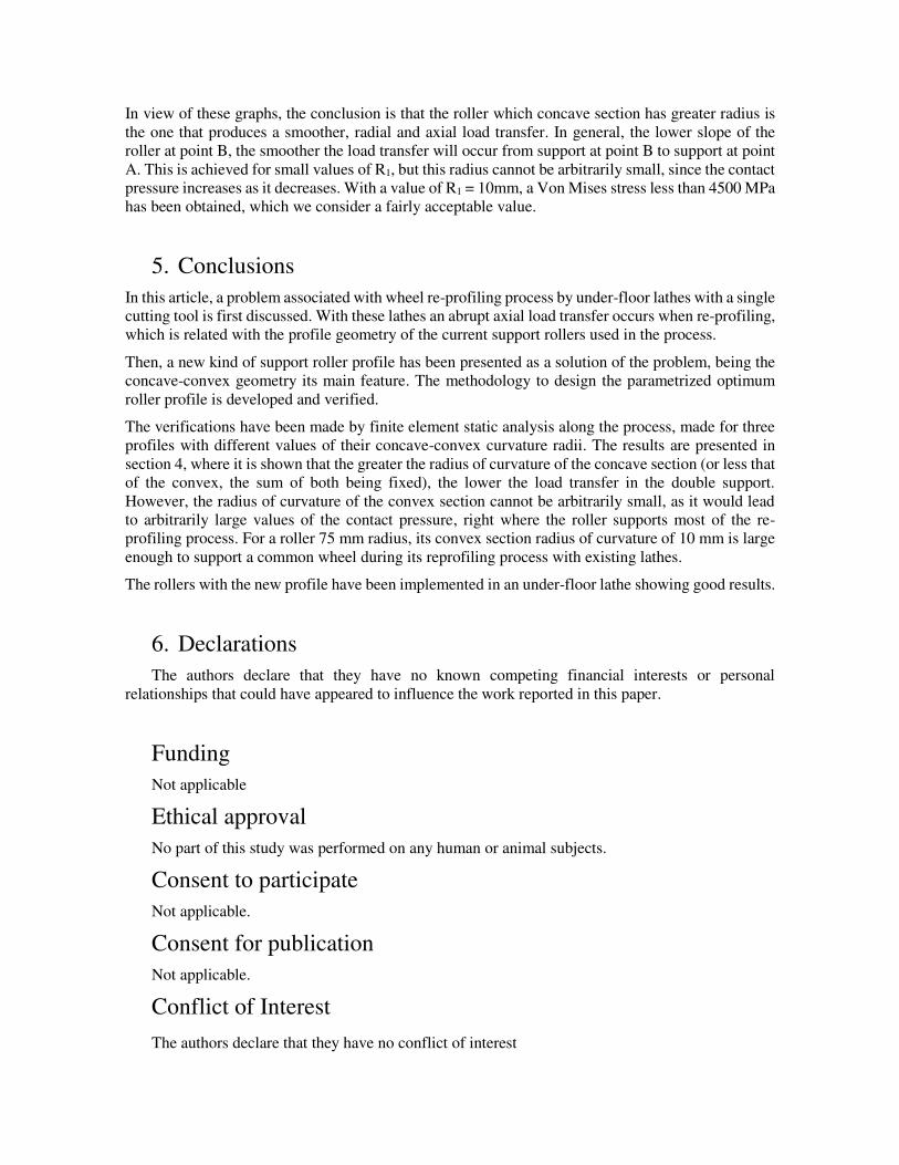
example, the Danobat under wheel lathe (see Image 1) is a specific machine tool for the corrective
maintenance of railway rolling surfaces. It can perform the re-profiling without the need for
dismounting the train axle and is equipped with the latest technology. The Stanray TM Underfloor
Wheel Truing Machine (TN-84C) [ 22] is an underfloor pit-mounted milling machine capable of
simultaneously re-profiling both wheels of a railway wheel set using the axle centers as the machining
reference point.
At the moment, there are not many studies on re-profiling in the literature. Some scholars carried out
studies on wheel re-profiling strategy and profile optimization design; Zhang et al. proposed a
multiobjective optimized re-profiling model that helped to reduce re-profiling quantity and made it
possible for wheels with abrasion loss to attain comprehensive performance of master profile thereby
extending their service life [ 23]. Chien et al. studied wheel wear statistical data processing method
based on mathematical statistics and built a wheel re-profiling period prediction model [ 24]. With
respect to wheel tread re-profiling process, many scholars have carried out research. Seo et al. studied
effects of metal removal and residual stress on the contact fatigue life of railway wheels by applying

finite element analyses and conducting corresponding fatigue test. [ 25]. Resilient wheels are made to
reduce noise and improve comfort of travelling with lightweight railways. This solution may be a
problem during turning of such wheelset on axle turning lathes. The biggest problem in turning
resilient wheelsets on wheel-turning lathes with friction drive appears to be axial deformation of
wheel during the machining process. Filipowicz et al. used a FEM model to check if turning of
resilient wheelsets on friction drive lathe is possible. The results showed that although cutting forces
are very high, values of radial displacement are not big, and they do not have influence on geometry
of machined type, especially while turning [ 26]. There are many different types of milling cutters for
wheel tread re-profiling. Sometimes choosing a reasonable milling cutter to reduce processing costs
at wheel tread re-profiling is quite difficult. Based on the experimental research, Tian analyzed the
difference of the total using cost of different milling cutters and provided the theoretical basis for the
economic selection of milling cutters [ 27]. Cioboata et al. presented some considerations on the
development of a technological system for profiling/re-profiling and measurement of the profile of
the railway wheel sets in order to improve maintenance of railway transport [ 28]. Andrade and Stow
assessed the technical efficiency of different operators turning railway wheelsets on an underfloor
wheel lathe, using a stochastic frontier analysis, and taking into account other explaining variables
such as the flange thickness and the occurrence of rolling contact fatigue defects, wheel flats, and
cavities[ 29]
In summary, researchers have so far made a great deal of research and got lots of achievements
regarding wheel profile optimization, machined surface, cutting heat and cutting force, and so forth
during metal cutting. However, after extensive consultation, the authors have not found literature on
the optimal shape of the support rollers used in underfloor lathes for railway wheel re-profiling.
Locomotive researchers and railway operators should always bear in mind the way to reduce residual
stress at wheel tread, surface roughness and wheel damage during wheel tread re-profiling and avoid
impacts, thereby extending the life cycle of wheelsets and minimizing the wheelset maintenance cost.
This paper proposes a method to find the optimal shape of the support rollers of a single tool
underfloor wheel lathe, to avoid sudden load transfers during the process. The new shape of the roller
profile has been analyzed through the dynamic simulation analysis of the wheel re-profiling process
by means of a finite element method.
Figure 1. Single tool underfloor wheel lathe for railway wheel re-profiling
2. Description of the problem associated with a single tool under-
floor lathe for railway wheel re-profiling
In this section, the problem associated with a single tool underfloor lathe equipped with support rollers
(two rollers for each wheel, at least one of them motorized) is described.
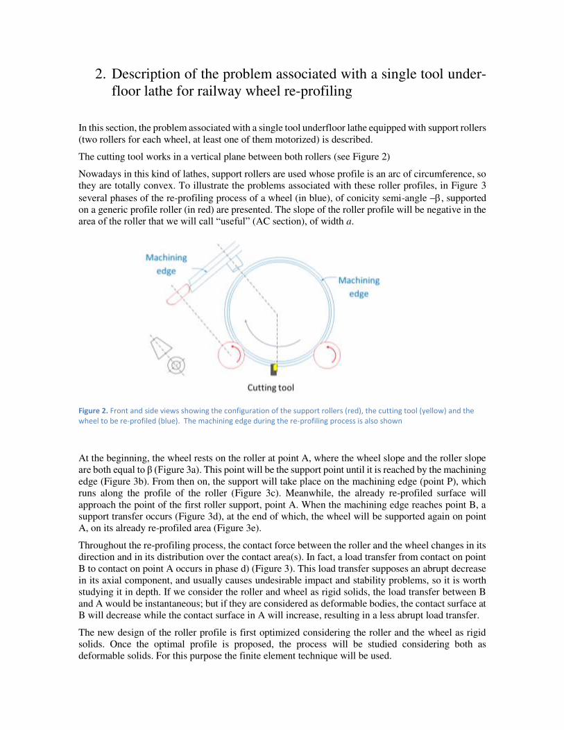
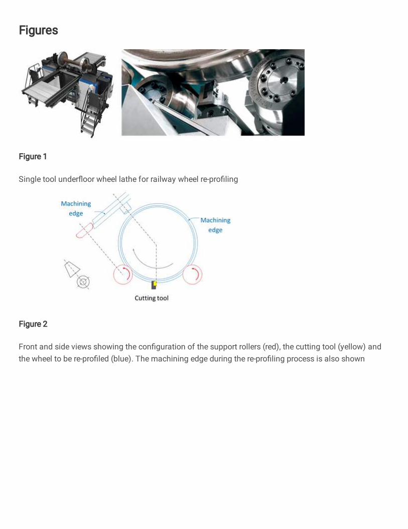
The cutting tool works in a vertical plane between both rollers (see Figure 2)
Nowadays in this kind of lathes, support rollers are used whose profile is an arc of circumference, so
they are totally convex. To illustrate the problems associated with these roller profiles, in Figure 3
several phases of the re-profiling process of a wheel (in blue), of conicity semi-angle , supported
on a generic profile roller (in red) are presented. The slope of the roller profile will be negative in the
area of the roller that we will call “useful” (AC section), of width a.
Figure 2. Front and side views showing the configuration of the support rollers (red), the cutting tool (yellow) and the
wheel to be re-profiled (blue). The machining edge during the re-profiling process is also shown
At the beginning, the wheel rests on the roller at point A, where the wheel slope and the roller slope
are both equal to β (Figure 3a). This point will be the support point until it is reached by the machining
edge (Figure 3b). From then on, the support will take place on the machining edge (point P), which
runs along the profile of the roller (Figure 3c). Meanwhile, the already re-profiled surface will
approach the point of the first roller support, point A. When the machining edge reaches point B, a
support transfer occurs (Figure 3d), at the end of which, the wheel will be supported again on point
A, on its already re-profiled area (Figure 3e).
Throughout the re-profiling process, the contact force between the roller and the wheel changes in its
direction and in its distribution over the contact area(s). In fact, a load transfer from contact on point
B to contact on point A occurs in phase d) (Figure 3). This load transfer supposes an abrupt decrease
in its axial component, and usually causes undesirable impact and stability problems, so it is worth
studying it in depth. If we consider the roller and wheel as rigid solids, the load transfer between B
and A would be instantaneous; but if they are considered as deformable bodies, the contact surface at
B will decrease while the contact surface in A will increase, resulting in a less abrupt load transfer.
The new design of the roller profile is first optimized considering the roller and the wheel as rigid
solids. Once the optimal profile is proposed, the process will be studied considering both as
deformable solids. For this purpose the finite element technique will be used.

Figure 2. Cross section of roller and wheel at different re-profiling phases (the cutting tool drawn in a) is out of section)
3. Roller profile design
In the intermediate phase of the re-profiling process, when the roller-wheel contact occurs on the
machining edge, point P (figure 1c), the already re-profiled surface of the wheel approaches towards
point A of the roller, where it will eventually be supported again.
In Figure 4 two moments of the re-profiling process separated by a small time interval, t (in blue
and purple, respectively) have been represented. Va and Vm are the approach and machining speeds
respectively, s is the distance between contact points at t and t+t. It can be seen that the greater the
difference between the inclination of the wheel, and the slope of the roller profile in the contact, , the greater the speed with which the re-profiled surface approaches to point A.

Figure 3 a) Two succesive positions (separated by the time Interval t) of the wheel being re-profiling (in blue and
purple, respectively) supported on the roller (in red). b) detail of the shaded area showing the involved velocities
(machining velocity, Vm ; and approach velocity, Va) and angles (slope of the wheel, ; and that of the roller profile at the
contact, ).
In fact, from Figure 4 we have:
Va = Vm sin(γ−β)cosγ (1)
In rollers whose useful profile is totally convex, as those used at present, the slope of the roller is a
monotonous diminishing function, reason why it goes away of the value of the inclination of the
wheel as the machining edge moves away from point A. Therefore, the approach speed increases as
the re-profiling process progresses, and can become considerably high at the time just before the
double support (phase d in Figure 3), producing a more abrupt load transfer than desired.
Note that for rollers with a totally convex profile, the load transfer between points A and B is
accompanied by a discontinuity in the axial component of the roller-wheel contact force: in B it is
much larger than in A (see Figure 3)
For the load transfer to be smooth enough, the slope of the roller profile at point B should be only
slightly higher than the wheel inclination (which coincides with the slope of the roller at point A, the
flank of the wheel considered linear). Thus, the curve proposed as the roller useful profile has an
inflection point, where it becomes from convex to concave. The designed profile must also ensure
that the second support is made actually at point A, before:
i) the machining edge leaves the useful area of the profile, and
ii) the support is produced at a point other than A, on a not yet re-profiled area (undesirable
support).
These two undesirable circumstances, represented in Figure 5, would both imply impulsive support
at point A.
Figure 5. Situations that lead to a second impulsive support of the wheel in the re-profiling process: i) the re-profiling
edge leaves the area of useful width prematurely (left); ii) there is prior undesirable support (right).
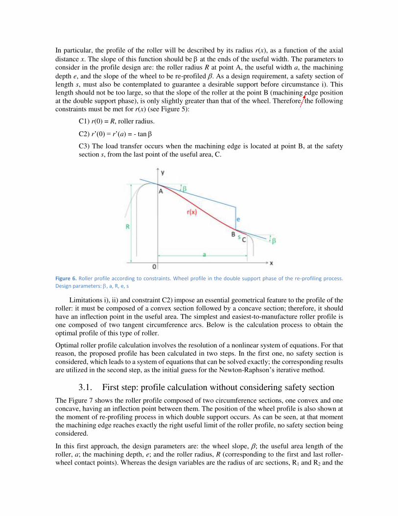
In particular, the profile of the roller will be described by its radius r(x), as a function of the axial
distance x. The slope of this function should be at the ends of the useful width. The parameters to
consider in the profile design are: the roller radius R at point A, the useful width a, the machining
depth e, and the slope of the wheel to be re-profiled . As a design requirement, a safety section of
length s, must also be contemplated to guarantee a desirable support before circumstance i). This
length should not be too large, so that the slope of the roller at the point B (machining edge position
at the double support phase), is only slightly greater than that of the wheel. Therefore, the following
constraints must be met for r(x) (see Figure 5):
C1) r(0) = R, roller radius.
C2) r’(0) = r’(a) = - tan
C3) The load transfer occurs when the machining edge is located at point B, at the safety
section s, from the last point of the useful area, C.
Figure 6. Roller profile according to constraints. Wheel profile in the double support phase of the re-profiling process.
Design parameters: , a, R, e, s
Limitations i), ii) and constraint C2) impose an essential geometrical feature to the profile of the
roller: it must be composed of a convex section followed by a concave section; therefore, it should
have an inflection point in the useful area. The simplest and easiest-to-manufacture roller profile is
one composed of two tangent circumference arcs. Below is the calculation process to obtain the
optimal profile of this type of roller.
Optimal roller profile calculation involves the resolution of a nonlinear system of equations. For that
reason, the proposed profile has been calculated in two steps. In the first one, no safety section is
considered, which leads to a system of equations that can be solved exactly; the corresponding results
are utilized in the second step, as the initial guess for the Newton-Raphson’s iterative method.
3.1. First step: profile calculation without considering safety section
The Figure 7 shows the roller profile composed of two circumference sections, one convex and one
concave, having an inflection point between them. The position of the wheel profile is also shown at
the moment of re-profiling process in which double support occurs. As can be seen, at that moment
the machining edge reaches exactly the right useful limit of the roller profile, no safety section being
considered.
In this first approach, the design parameters are: the wheel slope, ; the useful area length of the
roller, a; the machining depth, e; and the roller radius, R (corresponding to the first and last roller-
wheel contact points). Whereas the design variables are the radius of arc sections, R1 and R2 and the

position coordinates for the corresponding centres (X1,Y1) and (X2,Y2). These variables must fulfil
the following system of equations (see Figure 7):
{ X1 = −R1 sinβY1 = R − R1 cosβX2 = a + R2 sin βY2 = R + R2 cos β − a · tan β − e(X2 − X1)2 + (Y2 − Y1)2 = (R1 + R2)2 (2)
Figure 7. Roller profile composed of two circumference sections. Positions of the circumference centres and radios. First
approach design without considering safety distance.
There are 5 equations for 6 variables, so just one variable is independent. The radius of one of the arc
sections (R1, for example) can be taken as the independent variable, the rest of variables being
expressed as function of R1. The system is not linear but it can be solved exactly. Actually, replacing
the first 4 equations in the last one and operating, we get:
R2 = a2+(a·tanβ+e)22e − R1 (3)
The value for the rest of the variables is then obtained immediately.
If the profile is required to have one convex section followed by a concave one (as in Figure 7), the
value chosen for 𝑅1 cannot be arbitrarily large, since the sum of radii 𝑅1 + 𝑅2 has a fixed value for
a set of parameters , a, e. This implies the following limit for 𝑅1: R1 < a2+(a·tanβ+e)22e (4)
Otherwise, the value of 𝑅2 would be negative and the useful profile area would no longer have a
concave section. Of course, a negative value of 𝑅1 implies that the entire useful profile is concave.
In theory, it is desirable a large value of the concave arc section, so that the double support occurs
more smoothly. However, the convex arc section should be sufficiently large to ensure a sturdy and
stable support, since the wheel will rest on that area during most of the re-profiling process.
Furthermore, the smaller the radius of a section, the greater the variation of the axial component of
the roller-wheel force during the passage of the machining edge through that section.
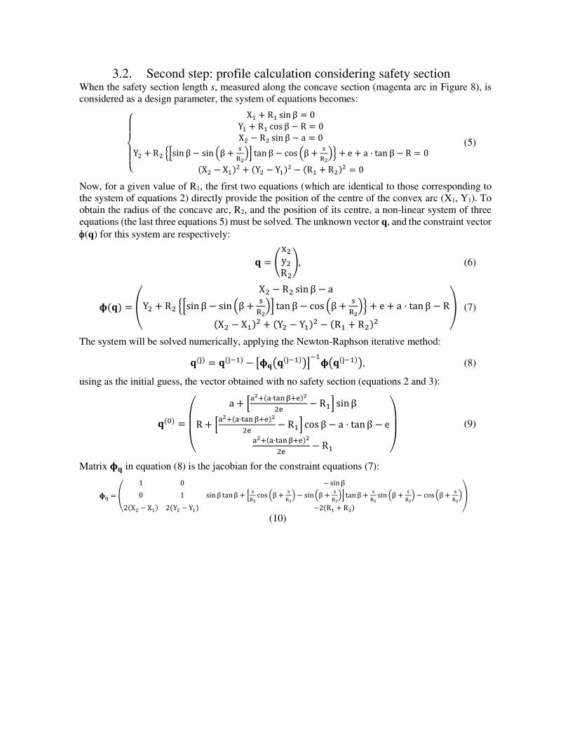
3.2. Second step: profile calculation considering safety section When the safety section length s, measured along the concave section (magenta arc in Figure 8), is
considered as a design parameter, the system of equations becomes:
{ X1 + R1 sin β = 0Y1 + R1 cos β − R = 0X2 − R2 sin β − a = 0Y2 + R2 {[sin β − sin (β + sR2)] tan β − cos (β + sR2)} + e + a · tan β − R = 0(X2 − X1)2 + (Y2 − Y1)2 − (R1 + R2)2 = 0
(5)
Now, for a given value of R1, the first two equations (which are identical to those corresponding to
the system of equations 2) directly provide the position of the centre of the convex arc (X1, Y1). To
obtain the radius of the concave arc, R2, and the position of its centre, a non-linear system of three
equations (the last three equations 5) must be solved. The unknown vector q, and the constraint vector
(q) for this system are respectively:
𝐪 = (x2y2R2), (6)
𝛟(𝐪) = ( X2 − R2 sinβ − aY2 + R2 {[sin β − sin (β + sR2)] tan β − cos (β + sR2)} + e + a · tan β − R(X2 − X1)2 + (Y2 − Y1)2 − (R1 + R2)2 ) (7)
The system will be solved numerically, applying the Newton-Raphson iterative method:
𝐪(j) = 𝐪(j−1) − [𝛟𝐪(𝐪(j−1))]−1𝛟(𝐪(j−1)), (8)
using as the initial guess, the vector obtained with no safety section (equations 2 and 3):
𝐪(0) = ( a + [a2+(a·tanβ+e)22e − R1] sinβR + [a2+(a·tanβ+e)22e − R1] cos β − a · tan β − ea2+(a·tanβ+e)22e − R1 )
(9)
Matrix 𝛟𝐪 in equation (8) is the jacobian for the constraint equations (7):
𝛟q = ( 1 0 −sinβ0 1 sin β tanβ + [ sR2 cos (β + sR2) − sin(β + sR2)] tanβ + sR2 sin (β + sR2) − cos (β + sR2)2(X2 − X1) 2(Y2 − Y1) −2(R1 + R2) )
(10)
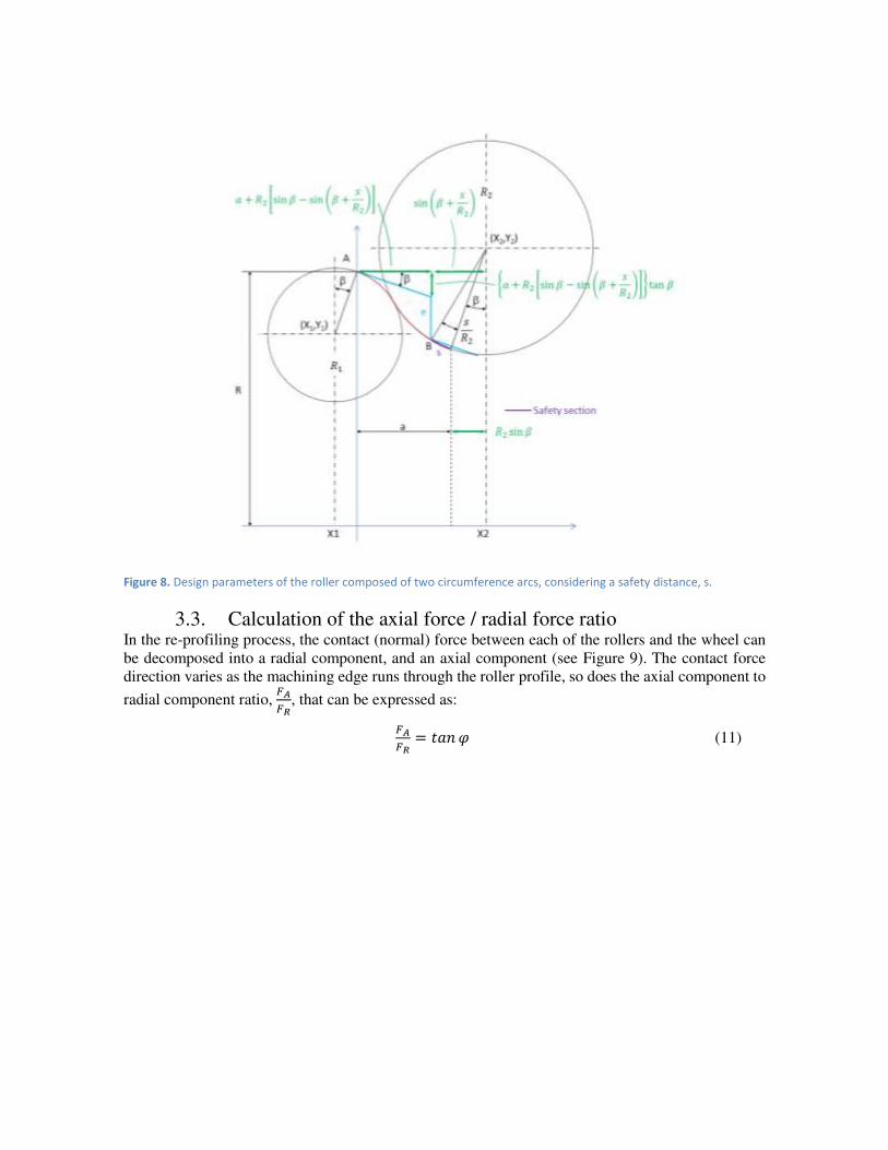
Figure 8. Design parameters of the roller composed of two circumference arcs, considering a safety distance, s.
3.3. Calculation of the axial force / radial force ratio In the re-profiling process, the contact (normal) force between each of the rollers and the wheel can
be decomposed into a radial component, and an axial component (see Figure 9). The contact force
direction varies as the machining edge runs through the roller profile, so does the axial component to
radial component ratio, 𝐹𝐴𝐹𝑅, that can be expressed as:
𝐹𝐴𝐹𝑅 = 𝑡𝑎𝑛𝜑 (11)
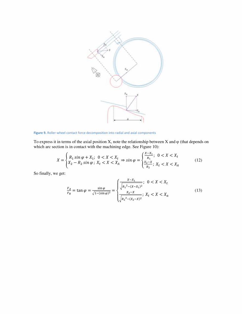
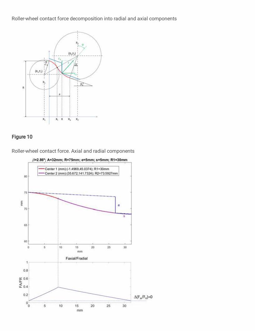
Figure 9. Roller-wheel contact force decomposition into radial and axial components
To express it in terms of the axial position X, note the relationship between X and (that depends on
which arc section is in contact with the machining edge. See Figure 10):
𝑋 = { 𝑅1 𝑠𝑖𝑛 𝜑 + 𝑋1; 0 < 𝑋 < 𝑋𝑡𝑋2 − 𝑅2 𝑠𝑖𝑛 𝜑 ; 𝑋𝑡 < 𝑋 < 𝑋𝐴 ⇒ 𝑠𝑖𝑛𝜑 = { 𝑋−𝑋1𝑅1 ; 0 < 𝑋 < 𝑋𝑡𝑋2−𝑋𝑅2 ; 𝑋𝑡 < 𝑋 < 𝑋𝐴 (12)
So finally, we get:
𝐹𝐴𝐹𝑅 = tan𝜑 = sin𝜑√1−(sin𝜑)2 = {
𝑋−𝑋1√𝑅12−(𝑋−𝑋1)2 ; 0 < 𝑋 < 𝑋𝑡𝑋2−𝑋√𝑅22−(𝑋2−𝑋)2 ; 𝑋𝑡 < 𝑋 < 𝑋𝑎 (13)

Figure 10. Roller-wheel contact force. Axial and radial components
A MATLAB® code has been developed to perform the described iterative calculation and the
calculations necessary to obtain the output results: X1, Y1, R2, X2, Y2 and FA/FR from the input
parameters: , a, R, e, s, R1. The program also provides the graph of the roller profile together with
the wheel profile in the double support position, and that of the roller-wheel contact force axial to
radial components ratio. As an example, in Figure 11 these graphics are shown for the following
parameters: = 2.86º, a = 32 mm, R = 75 mm, e = 5 mm, s = 5 mm, R1 = 30 mm. The output results
are also shown.
Note that no practical axial load transfer occurs, as the final FA/FR value (support at point B)
practically coincides with the initial one (support at point A). On the contrary, with conventional
convex rollers, the FA/FR curve is monotonous increasing up to the point of load transfer, causing an
abrupt decrease in the axial load component (see Figure 12).

Figure 11. Top: optimal roller profile for the indicated design parameters. Bottom: ratio between the axial and radial
components of the contact force, throughout the re-profiling process. the axial component grows to a maximum just at
the inflection point of the profile. From that point on, it decreases to the same value as in the first support. As a
consequence, there is no axial load transfer.

Figure 12. Top: Convex roller profile for the indicated design parameters. Bottom: ratio between the axial and radial
components of the contact force, throughout the re-profiling process. In this case, an abrupt load transfer occurs in the
second support.
4. Finite element simulation of the load transfer in the double
support phase
In this section, finite element results for the quasi-static load transfer process (phase d in Figure 3)
are shown. The objective is to provide a criterion for choosing the convex arc radius, R1.
To this end, 3 rollers of parameters β = 2.86 °, a = 32mm, e = 5mm, R = 75mm, s = 4mm, were simulated for 3 different values of the radius of curvature of the convex arc, R1 = {10mm, 50mm,
80mm}. The corresponding profiles are shown in Figure 13, together with the calculated values of
the second radius of curvature (concave arc), and the positions of the two centres of curvature, in
Cartesian coordinates (x, y).

Figure 13. Roller profiles used in load transfer simulations at the double support phase
Figure 14. FEM graphs corresponding to the beginning (top) and end (bottom) of the double support phase
R1=10mm; R2=95.1mm
Centre positions (mm):
C1=(-0.5,65.0); C2=(36.7,163.3)
R1=50mm; R2=53.9mm
Centre positions (mm):
C1=(-2.5,25.1); C2=(34.7,122.1)
R1=80mm; R2=19.8mm
Centre positions (mm):
C1=(-4.0,-4.9); C2=(33.0,87.8)
RA
DIA
L D
IST
AN
CE
(m
m)
RA
DIA
L D
IST
AN
CE
(m
m)
RA
DIA
L D
IST
AN
CE
(m
m)
RADIAL DISTANCE (mm)

In Figure 14 the beginning and the end of the double contact phase are shown for the first roller
(R1=10mm, R2=95.1mm), as obtained with a finite element software. Several static simulations have
been performed between these two positions for each of the three profiles mentioned above.
The most relevant results of the simulations are condensed in the graphs of Figure 15. The green
curves correspond to the roller with R1 = 10mm; the curves in orange, to the roller with R1 = 50mm;
and the curves in red, to the roller with R1 = 80mm. Solid lines are for (decreasing) contact forces at
point B, whereas dashed lines are for (increasing) contact forces at point A (for identification of points
A and B, see figures 2, 5, 7 or 12).
Figure 15. Radial and axial roller-wheel contact force transfer in the double-contact phase.
Green: R1 = 10mm; orange: R1 = 50mm; Red: R1 = 80mm.
Dashed line: contact force in the convex zone of the roller (point A). Solid line: contact force between the machining
edge and the concave zone of the roller (point B).
0
5
10
15
20
25
30
35
34 36 38 40 42
Fo
rce
(k
N)
Axial tool progress (mm)
Radial load transfer
0
2
4
6
8
10
12
14
16
34 36 38 40 42
Fo
rce
(k
N)
Axial tool progress (mm)
Axial load transfer
A
B
In view of these graphs, the conclusion is that the roller which concave section has greater radius is
the one that produces a smoother, radial and axial load transfer. In general, the lower slope of the
roller at point B, the smoother the load transfer will occur from support at point B to support at point
A. This is achieved for small values of R1, but this radius cannot be arbitrarily small, since the contact
pressure increases as it decreases. With a value of R1 = 10mm, a Von Mises stress less than 4500 MPa
has been obtained, which we consider a fairly acceptable value.
5. Conclusions
In this article, a problem associated with wheel re-profiling process by under-floor lathes with a single
cutting tool is first discussed. With these lathes an abrupt axial load transfer occurs when re-profiling,
which is related with the profile geometry of the current support rollers used in the process.
Then, a new kind of support roller profile has been presented as a solution of the problem, being the
concave-convex geometry its main feature. The methodology to design the parametrized optimum
roller profile is developed and verified.
The verifications have been made by finite element static analysis along the process, made for three
profiles with different values of their concave-convex curvature radii. The results are presented in
section 4, where it is shown that the greater the radius of curvature of the concave section (or less that
of the convex, the sum of both being fixed), the lower the load transfer in the double support.
However, the radius of curvature of the convex section cannot be arbitrarily small, as it would lead
to arbitrarily large values of the contact pressure, right where the roller supports most of the re-
profiling process. For a roller 75 mm radius, its convex section radius of curvature of 10 mm is large
enough to support a common wheel during its reprofiling process with existing lathes.
The rollers with the new profile have been implemented in an under-floor lathe showing good results.
6. Declarations
The authors declare that they have no known competing financial interests or personal
relationships that could have appeared to influence the work reported in this paper.
Funding
Not applicable
Ethical approval
No part of this study was performed on any human or animal subjects.
Consent to participate
Not applicable.
Consent for publication
Not applicable.
Conflict of Interest
The authors declare that they have no conflict of interest

Contributions
All the authors designed research, performed research, analyzed data, and wrote the paper.
Acknowledgement
This work was financially supported by the Spanish Government through the MCYT project 395
“RETOS2015: sistema de monitorización integral de conjuntos mecánicos críticos para la mejora del mantenimiento en el transporte-maqstatus.”
7. References
[ 1] M.J. Gómez, C. Castejón, E. Corral, J.C. García-Prada. Analysis of the influence of crack location for diagnosis in rotating
shafts based on 3 x energy. Mechanism and Machine Theory. Volume 103, 2016, Pages 167-173,ISSN 0094-114X,
https://doi.org/10.1016/j.mechmachtheory.2016.05.006.
[ 2] Gómez, M.J.; Corral, E.; Castejón, C.; García-Prada, J.C. Effective Crack Detection in Railway Axles Using Vibration
Signals and WPT Energy. Sensors 2018, 18, 1603.
[ 3 ]Gómez, M.J.; Castejón, C.; Corral, E.; García-Prada, J.C. Railway Axle Condition Monitoring Technique Based on Wavelet
Packet Transform Features and Support Vector Machines. Sensors 2020, 20, 3575.
[ 4] Li, Y.F.; Liu, J.X.;Wang, Y. Railway Wheel Flat Detection Based on Improved Empirical Mode Decomposition. Shock Vib.
2016, 2016. [CrossRef]
[ 5] Ling, L.; Cao, Y.B.; Xiao, X.B.; Wen, Z.F.; Jin, X.S. Efect of Wheel Flats on the High-speed Wheel-Rail Contact Behavior.
J. China Railw. Soc. 2015, 37, 32–39.
[ 6] Bogdevicius, M.; Zygiene, R.; Subacius, R. Employment of Two New Methods for the Research of Interaction of Wheel
with a Flat and Rail. Solid State Phenom. 2017, 260, 289–294. [CrossRef]
[ 7] Uzzal, R.U.A.; Ahmed, W.; Bhat, R.B. Impact analysis due to multiple wheel flats in three-dimensional railway vehicle-
track system model and development of a smart wheelset. Proc. Inst. Mech. Eng. Part F J. Rail Rapid Transit 2016, 230,
450–471. [CrossRef]
[ 8] Yang, J.; Thompson, D.J.; Takano, Y. Characterizing Wheel Flat Impact Noise with an E_cient Time Domain Model.
Notes Numer. Fluid Mech. Multidiscip. Des. 2015, 126, 109–116.
[ 9] Bogdevicius, M.; Zygiene, R.; Bureika, G.; Dailydka, S. An analytical mathematical method for calculation of the dynamic
wheel–rail impact force caused by wheel flat. Veh. Syst. Dyn. 2016, 54, 689–705. [CrossRef]
[ 10] Kaewunruen, S.; Remennikov, A.M. Impact responses of prestressing tendons in railway concrete sleepers in high
speed rail environments. In Proceedings of the 5th International Conference on Computational Methods in Structural
Dynamics and Earthquake Engineering, Crete Island, Greece, 25–27 May 2015.
[ 11] Zhang, Z.; Wei, S.; Andrawes, B.; Kuchma, D.A.; Edwards, J.R. Numerical and experimental study on dynamic
behaviour of concrete sleeper track caused by wheel flat. Int. J. Rail Transp. 2016, 4, 1–19.
[ 12] G. W. Yang, Y. J. Wei, G. L. Zhao et al., “Current research progress in the mechanics of high speed rails,” Advances in Mechanics, vol. 45, pp. 217–460, 2015.
[ 13] F. Braghin, S. Bruni, and F. Resta, “Wear of railway wheel profiles: A comparison between experimental results and a mathematical model,” Vehicle System Dynamics, vol. 37,pp. 478–489, 2003.
[ 14] W. J. Ren, D. B. Cui, L. Li, and J. Su, “Influence of wheel reprofiling on wheel-rail profile matching performance,” Lubrication Engineering, vol. 40, no. 5, pp. 16–21, 2015.
[ 15] M.H El-Axir. An investigation into roller burnishing. International Journal of Machine Tools and Manufacture, Volume
40, Issue 11, 2000, Pages 1603-1617, ISSN 0890-6955, https://doi.org/10.1016/S0890-6955(00)00019-5.

[ 16] Pascale Balland, Laurent Tabourot, Fabien Degre, Vincent Moreau, An investigation of the mechanics of roller
burnishing through finite element simulation and experiments, International Journal of Machine Tools and Manufacture,
Volume 65, 2013, Pages 29-36, ISSN 0890-6955, https://doi.org/10.1016/j.ijmachtools.2012.09.002.
[ 17] Koji Utsumi, Shoki Shichiri, Hiroyuki Sasahara, Determining the effect of tool posture on cutting force in a turn milling
process using an analytical prediction model, International Journal of Machine Tools and Manufacture, Volume 150, 2020,
103511, ISSN 0890-6955, https://doi.org/10.1016/j.ijmachtools.2019.103511.
[ 18] Bugra Kilic, Juan A. Aguirre-Cruz, Shivakumar Raman, Inspection of the cylindrical surface feature after turning using
coordinate metrology, International Journal of Machine Tools and Manufacture, Volume 47, Issues 12–13, 2007, Pages
1893-1903, ISSN 0890-6955, https://doi.org/10.1016/j.ijmachtools.2007.03.007.
[ 19] Ding, WF, Dai, CW , Yu, TY , Xu, JH , Fu, YC . Grinding performance of textured monolayer CBN wheels: Undeformed
chip thickness nonuniformity modeling and ground surface topography prediction International Journal of Machine Tools
and Manufacture, Volume122 Páginas: 52-66. DOI: 10.1016/j.ijmachtools.2017.05.006
[ 20] Hoon Huh, Jin Hyuck Heo, Hyoung Wook Lee. Optimization of a roller levelling process for Al7001T9 pipes with finite
element analysis and Taguchi method, International Journal of Machine Tools and Manufacture, Volume 43, Issue 4, 2003,
Pages 345-350, ISSN 0890-6955, https://doi.org/10.1016/S0890-6955(02)00269-9.
[ 21] Yanglin Peng, Yifan Dai, Ci Song, Feng Shi, Tool deflection model and profile error control in helix path contour
grinding, International Journal of Machine Tools and Manufacture, Volume 111, 2016, Pages 1-8, ISSN 0890-6955,
https://doi.org/10.1016/j.ijmachtools.2016.08.005.
[ 22] Simmons Machine Tool Corporation. Available at: http://smtgroup.com/products/underfloortechnology/underfloor-
wheel-truing-machine-stanray.
[ 23] B. Zhang, Z. Lu, and C. Tang, “Wheel reprofiling of high-speed EMU based on multi-objective optimization strategy,” Tongji Daxue Xuebao/Journal of Tongji University, vol. 41, no. 3, pp. 437–442, 2013.
[ 24] T. V. Chien, F. Li, Z. Qi, and J. J. Ding, “Processing method of locomotive wheel wear statistical data and prediction model of turning period,” Tiedao Xuebao/Journal of the China Railway Society, vol. 37, no. 12, pp. 14–19, 2015.
[ 25] J. W. Seo, B. C. Goo, J. B. Choi, and Y. J. Kim, “Effects of metal removal and residual stress on the contact fatigue life of railway wheels,” International Journal of Fatigue, vol. 30, no. 10-11, pp. 2021–2029, 2008.
[ 26] K. Filipowicz, W. Biedunkiewicz, M. Krolikowski, and D. Grzesiak, “Machining of resilient wheelsets on wheel-turning
lathes,” in DAAAM International Scientific Book 2010, 2010. [ 27] Z. Tian, “Economic selection of milling cutters for wheel tread reprofiling ofCRH2 type EMU,” ChinaHigh-tech
Enterprise, vol.no.18, pp. 102-103, 2014.
[ 28] D. Cioboata, A. Abalaru, D. Stanciu, L. Cristian, I. Ghionea, and S. Szekely, “Technological system for profiling/re-
profiling railway wheel sets,” Optics & Mechatronics, no. 47, pp. 79–85, 2015.
[ 29] A. R. Andrade and J. Stow, “Assessing the efficiency of maintenance operators: a case study of turning railway wheelsets on an under-floor wheel lathe,” Proceedings of the Institution of Mechanical Engineers, Part O: Journal of Risk and Reliability, vol. 231, no. 2, pp. 155–163, 2017.
Figures
Figure 1
Single tool under�oor wheel lathe for railway wheel re-pro�ling
Figure 2
Front and side views showing the con�guration of the support rollers (red), the cutting tool (yellow) andthe wheel to be re-pro�led (blue). The machining edge during the re-pro�ling process is also shown

Figure 3
Cross section of roller and wheel at different re-pro�ling phases (the cutting tool drawn in a) is out ofsection)
Figure 4
a) Two succesive positions (separated by the time Interval t) of the wheel being re-pro�ling (in blue andpurple, respectively) supported on the roller (in red). b) detail of the shaded area showing the involved

velocities (machining velocity, Vm ; and approach velocity, Va) and angles (slope of the wheel, ; and thatof the roller pro�le at the contact, ).
Figure 5
Situations that lead to a second impulsive support of the wheel in the re-pro�ling process: i) the re-pro�ling edge leaves the area of useful width prematurely (left); ii) there is prior undesirable support(right).
Figure 6
Roller pro�le according to constraints. Wheel pro�le in the double support phase of the re-pro�lingprocess. Design parameters: b, a, R, e, s
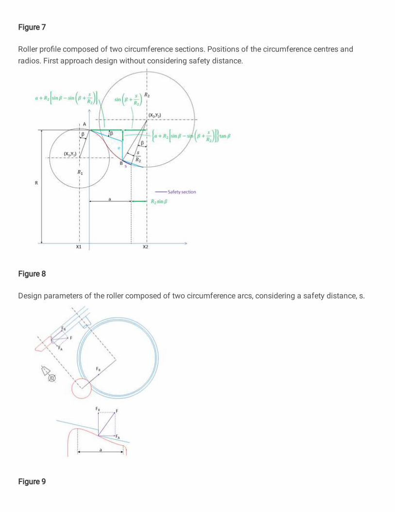
Figure 7
Roller pro�le composed of two circumference sections. Positions of the circumference centres andradios. First approach design without considering safety distance.
Figure 8
Design parameters of the roller composed of two circumference arcs, considering a safety distance, s.
Figure 9
Roller-wheel contact force decomposition into radial and axial components
Figure 10
Roller-wheel contact force. Axial and radial components

Figure 11
Top: optimal roller pro�le for the indicated design parameters. Bottom: ratio between the axial and radialcomponents of the contact force, throughout the re-pro�ling process. the axial component grows to amaximum just at the in�ection point of the pro�le. From that point on, it decreases to the same value asin the �rst support. As a consequence, there is no axial load transfer.
Figure 12
Top: Convex roller pro�le for the indicated design parameters. Bottom: ratio between the axial and radialcomponents of the contact force, throughout the re-pro�ling process. In this case, an abrupt load transferoccurs in the second support.

Figure 13
Roller pro�les used in load transfer simulations at the double support phase
Figure 14
FEM graphs corresponding to the beginning (top) and end (bottom) of the double support phase
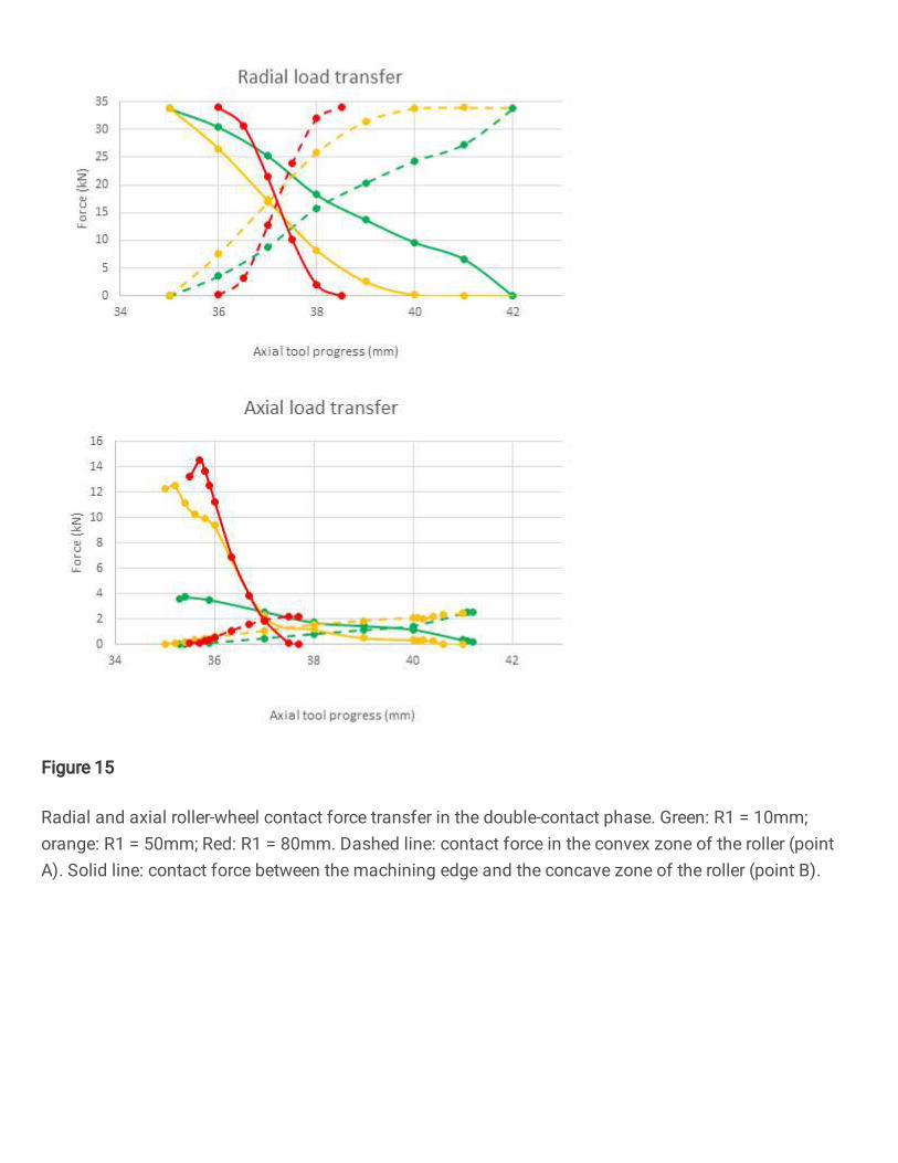
Figure 15
Radial and axial roller-wheel contact force transfer in the double-contact phase. Green: R1 = 10mm;orange: R1 = 50mm; Red: R1 = 80mm. Dashed line: contact force in the convex zone of the roller (pointA). Solid line: contact force between the machining edge and the concave zone of the roller (point B).