new products - omron industrial automation singapore products system expansion is time-consuming....
TRANSCRIPT

Co
mp
oB
us/S
Cat. N
o. Q
103-E
1-7
• Programmable Slaves • SYSMAC CPM2C CPU Units with CompoBus/S Master Functions • Waterproof Terminals• Sensor Terminals• Remote I/O Modules
New ProductsNew Products

System expansion
is time-consuming.
Complicated wiring between
the PC and repeater terminal
block.
Transmission of ON/OFF
signals is time-consuming.
Complicated sensor wiring.
Large wiring effort
required for dis-tributed devices han-
dling only a small number of I/O
points.
2
Table of contents2468
121418222527303234354245
51
59667280939699
102105107
FeaturesMaintenanceProgrammable SlavesCompoBus/S ProductsConnections to a Wider Range of Slaves Ensured by Upgraded ModelsCPM2C-S1 0C CPU Units with CompoBus/S MasterCPM2C-S1 0C-DRT Programmable SlavesSRM1-C01-V2/C02-V2 Master Control Units (S-Controllers)C200HW-SRM21-V1 Master UnitCQM1-SRM21-V1 Master UnitC200PC-ISA 3-SRM SYSMAC Boards with CompoBus/S MasterCPM2C-SRT21 I/O Link UnitCPM1A-SRT21 I/O Link UnitSRT2-ID/OD(-1) Transistor Remote I/O TerminalsSRT2- D16T(-1) Transistor Remote I/O Terminals with 3-tier Terminal BlockSRT2-R Relay-mounted Remote I/O TerminalsSRT2- D32ML(-1) Transistor Remote I/O Terminals with Connectors (32 Points)SRT2-VID/VOD(-1) Transistor Remote I/O Terminals with Connectors (8/16 Points)SRT2- D0 CL(-1) Waterproof TerminalsSRT2- D08S Sensor Terminals SRT1- D04S CompoBus/S Sensor Amplifier TerminalsSRT2-AD04 Analog Input TerminalSRT2-DA02 Analog Output TerminalSRT2-ID16P/OD16P Remote I/O ModulesFND-X -SRT Position DriversPeripheral DevicesOrdering Information
Dedi-cated cable
saves wiring ef-fort without re-peater termi-
nal block.
Distributed processing of a small number of
I/O points.
A cycle time of 1 ms
max. for up to 32 Slaves, 256
I/O points.
Sensor Amplifiers snap on to connect.
Easily connects
sensors and Slave Units.
T-branches
allow easy system
expansion.
3
Maximum Communications Cycle Time of Only 1 ms(High-speed Communications Mode)Exchanges 256 I/O points of data with a maximum of 32 Slaves at a maximum communications cycle time of only 1 ms per point.
Connects through a single dedicated cable, thus greatly saving wiring effort.Cabtire or flat cable is selectable.
Cabtire cable is available for multi-drop, T-branch, or multi-branch lines.Flat cable connects to T-branch connectors, thus ensuring ease of system expansion.Note: Cabtire and flat cables cannot be used together.
Long-distance Communications ModeWith a trunk line length of 500 m and a total branch line length of 100 m (2-conductor VCTF cable), you can branch in any way required using a special flat cable or a 4-conductor VCTF cable as long as the total wiring length is 200 m or less. Communicate at a cycle time of only 6 ms.*The Long-distance Communications Mode is not supported by the SRT1 Series.
An Analog Input Terminal with four points and an Analog Output Terminal with two points are available.

5
Repeater terminal blocks must be added and wired for I/O expansion.
1
2
Flat cable can be used with T-branch connectors which allow an increase in the number of Slaves.
2-conductor VCTF cable allows multi-branching, thus easily allowing an increase in the number of Slaves.
1
Individual wires must be replaced when using repeater terminal blocks.
Sensor Amplifier Terminals allow easy replacement of sensors through a snap-on attachment.
2CompoBus/S connector models allow snap-on attachment.
Maintenance
Expansion
4
Power supply
CompoBus/S
Terminatingresistance
Terminating resistance
Branch line length: 3 m max.
Main line length: 30 m max.Branch line length: 3 m max.
SYSMAC CS1
A
DC Branch line length: 3 m max.
B
Power supply
Main line
SYSMAC CS1
CompoBus/S
System Design
Using CompoBus/S Long-distance Communications Mode (with a Special Flat Cable or a 4-conductor VCTF cable) removes restrictions on main and branch line lengths. Branch freely up to a total cable length of 200 m.
* Baud rate: 750 kbps (in High-speed Communications Mode)* With 2-conductor VCTF cable (in High-speed Communications Mode), main line length: 100 m max.
* Baud rate: 93.75 kbps* Connect a terminating resistance at the end of the cable furthest from the Master.* With 2-conductor VCTF cable (in Long-distance Communications Mode), main line length: 500 m max.
One-touch expan-
sion with T-branching and branching of
branch lines.
With conventional High-speed Communications Mode, the following restrictions on the number of branching points and cable length had to be considered when designing the system.
With a Special Flat Cable or a 4-conductor VCTF cable:Main line length A: 30 m max. Branch line lengths B, C, and D: 3 m max. Total branch line length B + C + D: 30 m max.

CompoBus/S
76
Programmable Slaves combine devices, such as sensors and actuators, into one functional unit that is treated as a DeviceNet slave.
Programmable Slaves greatly facilitate device distribution and functional organization. They help standardize programming between units and reduce the amount of programming required at the master. I/O and operational checks can be performed for each functional unit, rather than waiting for final system assembly, as with conventional distributed I/O systems.
1,024-point I/O Links
ExplicitMessages
DeviceNet-CompoBus/S
Gateway
Multiword I/O links and explicit messages are used to control slaves from the master. Log data for communications can be sent in one operation whenever necessary using explicit messages.
FunctionsOMRON Programmable Slaves function as DeviceNet slaves, yet they provide PLC functionality to enable easy system expansion and create new potential.
2-ms Cycle Time(for 500 Steps)
High-speedCounter
No-protocolCommunications
Discrete I/O Relay Output Analog I/O Temperature Control
256-point(128/128) Expansion
High-speed Mode(0.8 ms, 100 m)
Long-distanceMode
(6 ms, 500 m)VCTF or Special
Flat CablesComplete
Product Line
Power Supply Unit
NT Links Host Links
InterruptInputs
256Timers/
Counters
Calendar/ClockPulse Output
Connected to bar code readers, Programmable Terminals, and other devices, the Programmable Slave processes data locally to reduce the load on the master.
Expansion Units
RS-232C
(3 max.)Just one Unit is required for each distributed block, reducing the number of interfaces for multipoint communications to, in turn, reduce costs.
Less wiring is required for terminal block expansions, connections to remote devices (such as signal lights or pushbutton switches), and connections to pneumatic valves and other non-OMRON products.

Master Units Slave Units
CompoBus/S Master Units
CompoBus/S Master Control Units
98
Transistor Remote I/O Terminals with 3-tier Terminal Block Relay-mounted Remote I/O Terminals
Transistor Remote I/O Terminals with Connectors
I/O Link Units
Note: SRT2- indicates NPN models and SRT2- -1 indicates PNP models.
SYSMAC Board with CompoBus/S Master Functions
CPU Units with CompoBus/S Master
Programmable Slaves
Transistor Remote I/O Terminals (NPN/PNP Output)
CPM2C-S100CCPM2C-S110C
SRM1-C01-V2
C200HW-SRM21-V1 CQM1-SRM21-V1
CPM2C-S100C-DRTCPM2C-S110C-DRT
SRT2-ID04(-1)4 inputs
SRT2-OD04(-1)4 outputs
SRM1-C02-V2CPM2C-SRT21 CPM1A-SRT21
C200PC-ISA 3-SRM
Without RS-232C port With RS-232C port
SRT2-ID08(-1)8 inputs
SRT2-OD08(-1)8 outputs
SRT2-ID16(-1)16 inputs
SRT2-OD16(-1)16 outputs
SRT2-ID16T(-1)
SRT2-ROC088 relay outputs
SRT2-ROC1616 relay outputs
SRT2-ROF088 power MOS FET relay outputs
SRT2- D32ML(-1)32 I/O points
SRT2-ROF1616 power MOS FET relay outputs
SRT2-V D08S(-1)8 I/O points
SRT2-V D16ML(-1)16 I/O points
Master Unit with 256 points Master Unit with 128 points
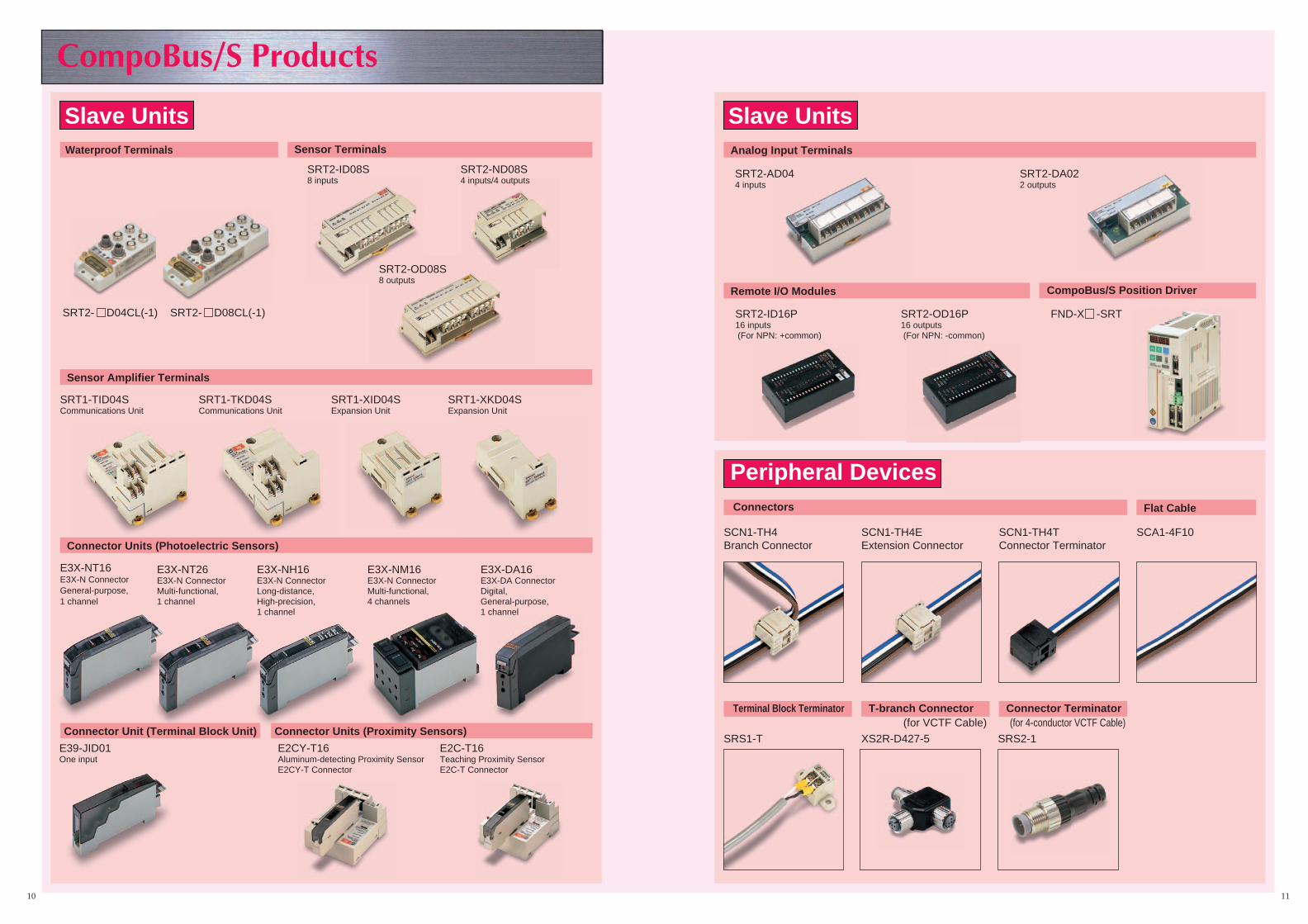
Peripheral Devices
SCN1-TH4 Branch Connector
Connectors
SCN1-TH4E Extension Connector
SCN1-TH4T Connector Terminator
XS2R-D427-5SRS1-T SRS2-1
Terminal Block Terminator T-branch Connector Connector Terminator
SCA1-4F10
Flat Cable
SRT2-ID16P 16 inputs (For NPN: +common)
SRT2-OD16P 16 outputs (For NPN: -common)
Slave Units
Remote I/O Modules CompoBus/S Position Driver
1110
Analog Input Terminals
FND-X -SRT
SRT1-TID04S Communications Unit
SRT1-TKD04S Communications Unit
SRT1-XID04S Expansion Unit
SRT1-XKD04S Expansion Unit
Slave UnitsWaterproof Terminals
E39-JID01 One input
Connector Unit (Terminal Block Unit) Connector Units (Proximity Sensors)
Sensor Terminals
SRT2- D04CL(-1) SRT2- D08CL(-1)
E3X-NT16 E3X-N Connector General-purpose, 1 channel
E3X-NT26 E3X-N Connector Multi-functional, 1 channel
E3X-NM16 E3X-N Connector Multi-functional, 4 channels
E3X-DA16E3X-DA ConnectorDigital, General-purpose,1 channel
E3X-NH16 E3X-N Connector Long-distance, High-precision, 1 channel
E2CY-T16Aluminum-detecting Proximity SensorE2CY-T Connector
E2C-T16Teaching Proximity SensorE2C-T Connector
(for VCTF Cable) (for 4-conductor VCTF Cable)
Connector Units (Photoelectric Sensors)
Sensor Amplifier Terminals
SRT2-AD04 4 inputs
SRT2-DA02 2 outputs
SRT2-ND08S4 inputs/4 outputs
SRT2-ID08S8 inputs
SRT2-OD08S8 outputs

12
Connections to a Wider Range of Slaves Ensured by Upgraded ModelsMaster Conventional
modelsNew models
C200HW-SRM21CQM1-SRM21
SRM1-C01SRM1-C02
SRM1-C01-V1SRM1-C02-V1
C200PC-ISA02-SRMC200PC-ISA12-SRM
C200HW-SRM21-V1CQM1-SRM21-V1
SRM1-C01-V2SRM1-C02-V2
C200PC-ISA03-SRMC200PC-ISA13-SRM
CPM2C-S100C (NEW)CPM2C-S110C (NEW)
CPM2C-S100C-DRT (NEW)CPM2C-S110C-DRT (NEW)
NKE-made UniwireC B /S S d
Communications mode
Slave
CompoBus/S SendUnit SDD-CS1
High-speedcommunica-tions mode
Long-distancecommunica-tions mode
SRT1 SeriesFND-X-SRT
YesYes
YesYes
NoNo
Existing product SRT2-AD04SRT2-DA02
YesYes
YesYes
YesYes
SRT2-V08S(-1)SRT2-D08S(-1)SRT2-D16ML(-1)SRT2-RO16
YesYesYesYes
YesYesYesYes
YesYesYesYes
SRT2-V08S(-1)SRT2-D16(-1)SRT2-RO08
YesYesYes
YesYesYes
YesYesYes
CPM2C-SRT21 Yes Yes Yes
SRT2-D32ML(-1) Yes Yes Yes
CPM1A-SRT21 Yes Yes Yes
New product SRT2-ID04CL(-1)SRT2-OD04CL(-1)SRT2-ID08CL(-1)SRT2-OD08CL(-1)
YesYesYesYes
YesYesYesYes
YesYesYesYes
SRT2-ID08SSRT2-ND08SSRT2-OD08S
YesYesYes
YesYesYes
YesYesYes
SRT2-ID16PSRT2-OD16P
YesYes
YesYes
YesYes
Note: 1. In high-speed communications mode, the maximum transmission distance is 100 m at a baud rate of 750 kbps. In long-distancecommunications mode (i.e., a newly available mode), the maximum transmission distance is 500 m at a baud rate of 93.75 kbps.
2. The SRT2-AD04 and SRT2-DA02 are available for 16-bit synchronous communications.
Company Product Model number Communications modep y
High-speedcommunications
mode
Long-distancecommunications
mode
CKD Solenoid valve for saving wiringff t
4TB1/2/3/4 Series Yes Yes (See note.)g geffort 4G Series Yes Yes (See note.)
MN4SO Series Yes Yes (See note.)
Parect regulator SDA-C Yes Yes
SMC Solenoid valve for SI manifold use VQ, SY, SX, SQ, SZ Series Yes Yes (See note.)
Koganei F-series solenoid valve YS2A1, YS2A2 Yes Yesg
X80M/X88M Series YS1A1, YS1A2 Yes Yes
JA-series solenoid valve YS5A1, YS5A2 Yes Yes
PA, PB-series solenoid valve YS4A1, YS4A2 Yes Yes
Note: Refer to the maker for information on long-distance communications mode.

CompoBus/S Connection Examples
13
High-speed ON/OFF Bus Communications in Remote I/O SystemsCabtire Cable Connections
CPM2C-S10C CPU Units withCompoBus/S Master (with 256 Points)CPM2C-S10C-DRT ProgrammableSlaves (with 256 I/O Points)
Masters
SRM1-C01-V2/SRM1-C02-V2Master Controllers(with 256 I/O Points)
CQM1-SRM21-V1Master Unit (with128 I/O Points)
C200HW-SRM21-V1Master Unit (with 256I/O Points)
C200PC-ISA3-SRM SYSMACBoards (with 256 I/O Points)3G8B3-SRM00/3G8B3-SRM01VME Boards (with 256 I/OPoints)
SYSMAC CPM2CSYSMAC CS1, α C200HX/HG/HE,C200HS
SYSMAC CQM1/H
SRT2-ID04(-1)/SRT2-ID08(-1)/SRT2-ID16(-1)SRT2-OD04(-1)/SRT2-OD08(-1)/SRT2-OD16(-1)Remote I/O Terminals (with4/8/16 Inputs or 4/8/16 Outputs)
SRT2-D08SSensor Terminals(with 4 Sensor Inputs,4 Sensor Outputs, or8 Sensor Inputs)
SRT2-D16T(-1)Transistor Remote I/OTerminals (3-tier TerminalBlock with 16 TransistorI/O Points)
SRT2-AD04Analog InputTerminal (with1 to 4 Inputs)
SRT2-DA02Analog OutputTerminal (with1 to 2 Outputs)
SRT2-ROC08/SRT2-ROC16SRT2-ROF08/SRT2-ROF16Relay-mounted Remote I/OTerminal (with 8 or 16outputs)
Slaves
Multi-branch-ing connec-tion
T-branchingconnection
Multidrop connectionCPM2CCPU Unit
CPM2C-SRT21I/O Link Unit(with 8 Inputsand 8 Outputs) CPM2A
CPU Unit
CPM1A-SRT21I/O Link Unit(with 8 Inputsand 8 Outputs)
SRT2-VID(-1)/VOD(-1)SRT2-D32ML(-1)Remote I/O Terminal(with Connector and 8,16, or 32 I/O Points)
FND-X--SRTPosition Drivers
SRS1-TTerminal-blockTerminator
Special Flat Cable Connection
CPM2C-S10C CPU Units withCompoBus/S Master (with 156 I/O Points)CPM2C-S10C-DRT ProgrammableSlaves (with 256 I/O Points)
Master SYSMAC CPM2C
SRM1-C01-V2/SRM1-C02-V2Master Controllers(with 256 I/O Points)
CQM1-SRM21-V1Master Unit (with128 I/O Points)
C200HW-SRM21-V1Master Unit (with 256I/O Points)
C200PC-ISA3-SRM SYSMACBoards (with 256 I/O Points)3G8B3-SRM00/3G8B3-SRM01VME Boards (with 256 I/O Points)
SYSMAC CS1, α C200HX/HG/HE,C200HS
SYSMAC CQM1/H
SlavesSRT2-ROC08/SRT2-ROC16SRT2-ROF08/SRT2-ROF16Relay-mounted RemoteTerminals (with 8 or 16 outputs)
SRT1-D04S SensorAmplifier Terminal forCompoBus/S (with 4 Inputsor 4 Outputs)
SRT2-DO8SSensor Terminal(with 4 SensorInputs, 4 SensorOutputs, or 8Sensor Inputs)
SRT2-ID04(-1)/SRT2-ID08(-1)/SRT2-ID16(-1)SRT2-OD04(-1)/SRT2-OD08(-1)/SRT2-OD16(-1)Remote I/O Terminals (with 4/8/16Inputs or 4/8/16 Outputs)
SCA1-4F10Special Flat CableSCN1-TH4T
Connector Terminator
Note: Cabtire cable and flat cable cannot be used together.

14
CPU Units with CompoBus/S Master CPM2C-S10C
Ultra-compact, Thin-profile CPM2C CPUUnit with CompoBus/S Master OfferingHigh-speed Bus Communications withNo Complicated Wiring
Ultra-compact, thin-profile design ideal for on-siteapplicationsUltra-compact at 40 x 90 x 65 mm (W x H x D) with10 I/O points and CompoBus/S Master offersversatile expandability to construct systemsmeeting on-site needs.
A large number of expansion I/O points reducessystem construction cost.Up to three Expansion Terminals can beconnected. Furthermore, CompoBus/S RemoteTerminals can be used for expansion I/O points.Not only in-panel wiring but also external wiring issimplified. Furthermore, the miniaturization of thecontrol panel reduces cable, terminal block, andwiring costs.
Easy System Designing, Modification, and Expan-sionCompoBus/S Remote Terminals with high-speedbus communications and no complicated wiringcan be used as expansion terminal blocks withminimal modifications as long as room forexpansion is reserved at the designing stage.
A calendar/clock ensures easy machinery control,including data collection and error logs with dateand time stamps. This functionality can be used asa weekly timer as well.
Terminal Block
PT
Master
Valves
CompoBus/S
Master I/O Link Unit
Machine
Machine
Control Panel

CPM2C-S10C CPM2C-S10C
15
Ordering InformationUnit Inputs Outputs Clock Model
10 points (6 inputs/4t t )
Connector model 6 points at 24 VDC 4 transistor sinking outputs Yes CPM2C-S100C(outputs) 4 transistor sourcing outputs Yes CPM2C-S110C
Specifications General Specifications
Item Specification
Control method Stored program method
I/O control method Cyclic scan method(Immediate refreshing can be performed with IORF(97).)
Programming language Ladder diagram
Instruction length 1 step per instruction1 to 5 words per instruction
Instructions Basic instructions 14
Specialinstructions
105 instructions, 185 variations
Execution time Basic instructions 0.64 µs (LD instruction)
Specialinstructions
7.8 µs (MOV instruction)
Program capacity 4,096 words
Max. I/O capacity CPU Unit only: 10 pointsExpansion I/O Unit: 96 points (32-point Expansion I/O Unit x 3)(Up to 3 Expansion Units can be connected.)CompoBus/S: 256 points (362 points in total)
Input bits IR 00000 to IR 00915(Bits not used for input bits can be used for work bits.)
Output bits IR 01000 to IR 01915(Bits not used for output bits can be used for work bits.)
CompoBus/S input bits 128 bits: IR 02000 to IR 02715 (words IR 020 to IR 027)
CompoBus/S output bits 128 bits: IR 03000 to IR 03715 (words IR 030 to IR 037)
Work bits 672 bits: IR 02800 to IR 02915 (words IR 028 to IR 029)IR 03800 to IR 03915 (words IR 038 to IR 039)IR 04000 to IR 04915 (words IR 040 to IR 049)IR 20000 to IR 22715 (words IR 200 to IR 227)
Special bits (SR area) 440 bits: SR 22800 to SR 25507 (words SR 228 to SR 255)
Temporary bits (TR area) 8 bits: (TR 0 to TR 7)
Holding bits (HR area) 320 bits: HR 0000 to HR 1915 (words HR 00 to HR 19)
Auxiliary bits (AR area) 384 bits: AR 0000 to AR 2315 (words AR 00 to AR 23)These include CompoBus/S slave status flags (words AR 04 to AR 07).
Link bits (LR area) 256 points: LR 0000 to LR 1515 (words LR 00 to LR 15)
Timers/Counters 256 timers/counters: TIM/CNT 000 to TIM/CNT 2551-ms timers: TMHH (--)10-ms timers: TIMH (15)100-ms timers TIM 1-s/10-s timers: TIML (--)Decrementing counters: CNTReversible counters: CNTR (12)
Data memory Read/Write 2,048 words (DM 0000 to DM 2047)The Error Log is contained in DM 2000 to DM 2021.
Read only 456 words (DM 6144 to DM 6599)
PC Setup 56 words (DM 6600 to DM 6655)
Basic interruptf ti
Interrupt inputs 2 interrupts (Used for both counter mode interrupts inputs and quick-response inputs.functions Scheduled
interrupts1 interrupt

CPM2C-S10C CPM2C-S10C
16
Item Specification
High-speedcounterf ti
High-speedcounters
1 counter (single phase at 20 kHz or 2 phases at 5 kHz)
functionsCounterinterrupts
1 interrupt (set value comparison or set-value range comparison)
Interrupt inputs(counter mode)
2 interrupts (Used for both external interrupts inputs and quick-response inputs.)
Count-upinterrupts
2 interrupts (Used for both external interrupts inputs and quick-response inputs.)
Quick-response inputs 2 points (Used for both external interrupts inputs and counter mode interrupt inputs.)Min. input pulse width: 50 µs max.
Pulse output 2 points with no acceleration/deceleration,10 Hz to 10 kHz each, and no direction control: 1 point with trapezoidacceleration/deceleration,10 Hz to 10 kHz with direction control: or 2 points with variable duty-ratio outputs
Synchronized pulse control 1 point
Input time constant(ON response time = OFF responsetime)
Can be set for CPU Unit inputs and Expansion Unit inputs only(1, 2, 3, 5, 10, 20, 40, or 80 ms)
Clock Equipped with clock (built-in RTC)
Communications functions Peripheral port: Supports Host Link, peripheral bus, no-protocol communications, andProgramming Console connections.RS-232C port: Supports Host Link, no-protocol communications, 1-to-1 Link, or 1-to-1 NT Linkconnections.
Power failure backup function Data in HR, AR, Counter (CNT), and Data Memory (DM) areas is held.
Memory backup Non-volatile (flash) memory: Program, read-only DM area, and PC Setupy
Memory backup (lithium battery: 2 years lifetime): DM area, HR area, AR area, and countervalues
Self-diagnostic functions CPU error (watchdog timer), memory errors, communications errors, setting errors, batteryerrors, and expansion I/O bus errors
Program check No END instruction, programming errors (checked when operation is started)
Programmingdevices
ProgrammingConsole
C200H-PRO27, CQM1-PRO01, or CQM1H-PRO01
SSS IBM PC/AT or compatible (SYSMAC Support Software version 1.1 or higher)
CPT Windows
CX-P Windows
Note: Connecting Cable (CPM2C-CN111, CS1W-CN114, or CS1W-CN118) is required to connect to the communications peripheral/RS-232C port.
CPM2C-S10C CPM2C-S10C
17
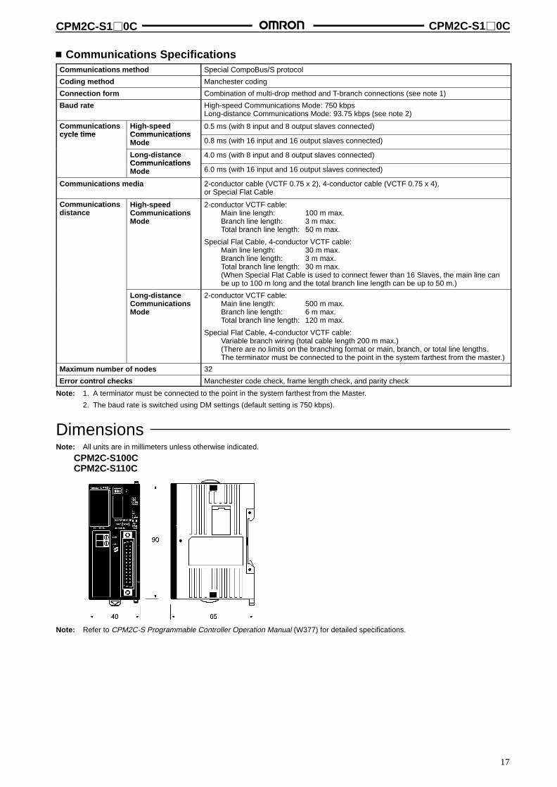
Communications SpecificationsCommunications method Special CompoBus/S protocol
Coding method Manchester coding
Connection form Combination of multi-drop method and T-branch connections (see note 1)
Baud rate High-speed Communications Mode: 750 kbpsLong-distance Communications Mode: 93.75 kbps (see note 2)
Communicationscycle time
High-speedComm nications
0.5 ms (with 8 input and 8 output slaves connected)cycle time Communications
Mode 0.8 ms (with 16 input and 16 output slaves connected)
Long-distanceComm nications
4.0 ms (with 8 input and 8 output slaves connected)CommunicationsMode 6.0 ms (with 16 input and 16 output slaves connected)
Communications media 2-conductor cable (VCTF 0.75 x 2), 4-conductor cable (VCTF 0.75 x 4),or Special Flat Cable
Communicationsdistance
High-speedCommunicationsMode
2-conductor VCTF cable:Main line length: 100 m max.Branch line length: 3 m max.Total branch line length: 50 m max.
Special Flat Cable, 4-conductor VCTF cable:Main line length: 30 m max.Branch line length: 3 m max.Total branch line length: 30 m max.(When Special Flat Cable is used to connect fewer than 16 Slaves, the main line canbe up to 100 m long and the total branch line length can be up to 50 m.)
Long-distanceCommunicationsMode
2-conductor VCTF cable:Main line length: 500 m max.Branch line length: 6 m max.Total branch line length: 120 m max.
Special Flat Cable, 4-conductor VCTF cable:Variable branch wiring (total cable length 200 m max.)(There are no limits on the branching format or main, branch, or total line lengths.The terminator must be connected to the point in the system farthest from the master.)
Maximum number of nodes 32
Error control checks Manchester code check, frame length check, and parity check
Note: 1. A terminator must be connected to the point in the system farthest from the Master.
2. The baud rate is switched using DM settings (default setting is 750 kbps).
DimensionsNote: All units are in millimeters unless otherwise indicated.
CPM2C-S100CCPM2C-S110C
Note: Refer to CPM2C-S Programmable Controller Operation Manual (W377) for detailed specifications.
18
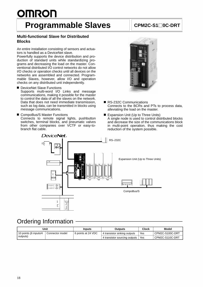
Programmable Slaves CPM2C-S10C-DRT
Multi-functional Slave for DistributedBlocks
An entire installation consisting of sensors and actua-tors is handled as a DeviceNet slave.Powerfully supports the device distribution and pro-duction of standard units while standardizing pro-grams and decreasing the load on the master. Con-ventional distributed I/O control networks do not allowI/O checks or operation checks until all devices on thenetworks are assembled and connected. Program-mable Slaves, however, allow I/O and operationchecks on any distributed unit independently.
DeviceNet Slave FunctionsSupports multi-word I/O Links and messagecommunications, making it possible for the masterto control the data of all the slaves on the network.Data that does not need immediate transmission,such as log data, can be transmitted in blocks usingmessage communications.
CompoBus/S Master FunctionsConnects to remote signal lights, pushbuttonswitches, terminal blocks, and pneumatic valvesfrom other companies over VCTF or easy-to-branch flat cable.
RS-232C CommunicationsConnects to the BCRs and PTs to process data,alleviating the load on the master.
Expansion Unit (Up to Three Units)A single node is used to control distributed blocksand decrease the size of the communications blockin multi-point operation, thus making the costreduction of the system possible.
RS–232C
Expansion Unit (Up to Three Units)
CompoBus/S
Ordering InformationUnit Inputs Outputs Clock Model
10 points (6 inputs/4t t )
Connector model 6 points at 24 VDC 4 transistor sinking outputs Yes CPM2C-S100C-DRT(outputs) 4 transistor sourcing outputs Yes CPM2C-S110C-DRT
CPM2C-S10C-DRT CPM2C-S10C-DRT
19
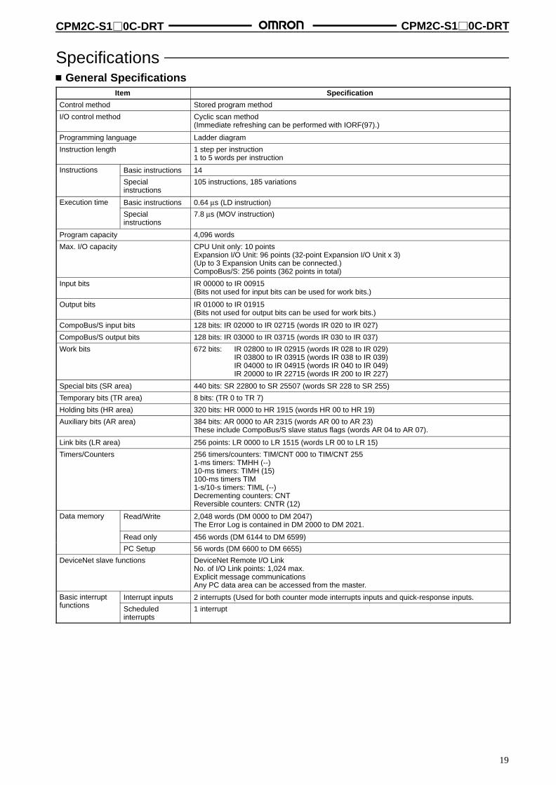
Specifications General Specifications
Item Specification
Control method Stored program method
I/O control method Cyclic scan method(Immediate refreshing can be performed with IORF(97).)
Programming language Ladder diagram
Instruction length 1 step per instruction1 to 5 words per instruction
Instructions Basic instructions 14
Specialinstructions
105 instructions, 185 variations
Execution time Basic instructions 0.64 µs (LD instruction)
Specialinstructions
7.8 µs (MOV instruction)
Program capacity 4,096 words
Max. I/O capacity CPU Unit only: 10 pointsExpansion I/O Unit: 96 points (32-point Expansion I/O Unit x 3)(Up to 3 Expansion Units can be connected.)CompoBus/S: 256 points (362 points in total)
Input bits IR 00000 to IR 00915(Bits not used for input bits can be used for work bits.)
Output bits IR 01000 to IR 01915(Bits not used for output bits can be used for work bits.)
CompoBus/S input bits 128 bits: IR 02000 to IR 02715 (words IR 020 to IR 027)
CompoBus/S output bits 128 bits: IR 03000 to IR 03715 (words IR 030 to IR 037)
Work bits 672 bits: IR 02800 to IR 02915 (words IR 028 to IR 029)IR 03800 to IR 03915 (words IR 038 to IR 039)IR 04000 to IR 04915 (words IR 040 to IR 049)IR 20000 to IR 22715 (words IR 200 to IR 227)
Special bits (SR area) 440 bits: SR 22800 to SR 25507 (words SR 228 to SR 255)
Temporary bits (TR area) 8 bits: (TR 0 to TR 7)
Holding bits (HR area) 320 bits: HR 0000 to HR 1915 (words HR 00 to HR 19)
Auxiliary bits (AR area) 384 bits: AR 0000 to AR 2315 (words AR 00 to AR 23)These include CompoBus/S slave status flags (words AR 04 to AR 07).
Link bits (LR area) 256 points: LR 0000 to LR 1515 (words LR 00 to LR 15)
Timers/Counters 256 timers/counters: TIM/CNT 000 to TIM/CNT 2551-ms timers: TMHH (--)10-ms timers: TIMH (15)100-ms timers TIM 1-s/10-s timers: TIML (--)Decrementing counters: CNTReversible counters: CNTR (12)
Data memory Read/Write 2,048 words (DM 0000 to DM 2047)The Error Log is contained in DM 2000 to DM 2021.
Read only 456 words (DM 6144 to DM 6599)
PC Setup 56 words (DM 6600 to DM 6655)
DeviceNet slave functions DeviceNet Remote I/O LinkNo. of I/O Link points: 1,024 max.Explicit message communicationsAny PC data area can be accessed from the master.
Basic interruptf ti
Interrupt inputs 2 interrupts (Used for both counter mode interrupts inputs and quick-response inputs.functions Scheduled
interrupts1 interrupt

CPM2C-S10C-DRT CPM2C-S10C-DRT
20
Item Specification
High-speedcounterf ti
High-speedcounters
1 counter (single phase at 20 kHz or 2 phases at 5 kHz)
functionsCount erinterrupts
1 interrupt (set value comparison or set-value range comparison)
Interrupt inputs(counter mode)
2 interrupts (Used for both external interrupts inputs and quick-response inputs.)
Count-upinterrupts
2 interrupts (Used for both external interrupts inputs and quick-response inputs.)
Quick-response inputs 2 points (Used for both external interrupts inputs and counter mode interrupt inputs.)Min. input pulse width: 50 µs max.
Pulse output 2 points with no acceleration/deceleration,10 Hz to 10 kHz each, and no direction control: 1 point with trapezoidacceleration/deceleration,10 Hz and 10 kHz with no direction control: or 2 points with variable duty-ratio outputs
Synchronized pulse control 1 point
Input time constant(ON response time = OFF responsetime)
Can be set for CPU Unit inputs and Expansion Unit inputs only(1, 2, 3, 5, 10, 20, 40, or 80 ms)
Clock Equipped with clock (built-in RTC)
Communications functions Peripheral port: Supports Host Link, peripheral bus, no-protocol communications, andProgramming Console connections.RS-232C port: Supports Host Link, no-protocol communications, 1-to-1 Link, or 1-to-1 NT Linkconnections.
Power failure backup function Data in HR, AR, Counter (CNT), and Data Memory (DM) areas is held.
Memory backup Non-volatile (flash) memory: Program, read-only DM area, and PC Setupy
Memory backup (lithium battery: 2 years lifetime): DM area, HR area, AR area, and countervalues
Self-diagnostic functions CPU error (watchdog timer), memory errors, communications errors, setting errors, batteryerrors, and expansion I/O bus errors
Program check No END instruction, programming errors (checked when operation is started)
Programmingdevices
ProgrammingConsole
C200H-PRO27, CQM1-PRO01, or CQM1H-PRO01
SSS IBM PC/AT or compatible (SYSMAC Support Software version 1.1 or higher)
CPT Windows
CX-P Windows
Note: Connecting Cable (CPM2C-CN111, CS1W-CN114, or CS1W-CN118) is required to connect to the communications peripheral/RS-232C port.
Communications SpecificationsDeviceNetCommunications protocol DeviceNet
Connection form Combination of multi-drop and T-branch connections (see note 1)
Baud rate 500, 250, or 125 kbps (switchable)
Communications media Special 5-conductor cable (2 signal lines, 2 power supply lines, and 1 shield line)
Communicationsdistance
Baud rate 500 kbps:Max. network length (see note 2): 100 m max. (see note 3)Main line length: 6 m max.Total branch line length: 39 m max.
250 kbps:Max. network length (see note 2): 250 m max. (see note 3)Main line length: 6 m max.Total branch line length: 78 m max.
125 kbps:Max. network length (see note 2): 500 m max. (see note 3)Main line length: 6 m max.Total branch line length: 156 m max.
Max. number of connecting nodes 64 (63 slaves and 1 master)
Error control checks CRC error, node address duplication check, and scan list verification
Note: 1. A terminator must be connected to the point in the system farthest from the Master.
2. The maximum network length is the distance from the master to the farthest node.

CPM2C-S10C-DRT CPM2C-S10C-DRT
21
3. When Thin Cable is used for the main line, the main line must be 100 m or less in length.
CompoBus/SCommunications method Special CompoBus/S protocol
Coding method Manchester coding
Connection form Combination of multi-drop method and T-branch connections (see note 1)
Baud rate High-speed Communications Mode: 750 kbpsLong-distance Communications Mode: 93.75 kbps (see note 2)
Communicationscycle time
High-speedComm nications
0.5 ms (with 8 input and 8 output slaves connected)cycle time Communications
Mode 0.8 ms (with 16 input and 16 output slaves connected)
Long-distanceComm nications
4.0 ms (with 8 input and 8 output slaves connected)CommunicationsMode 6.0 ms (with 16 input and 16 output slaves connected)
Communications media 2-conductor cable (VCTF 0.75 x 2), 4-conductor cable (VCTF 0.75 x 4),or Special Flat Cable
Communicationsdistance
High-speedCommunicationsMode
2-conductor VCTF cable:Main line length: 100 m max.Branch line length: 3 m max.Total branch line length: 50 m max.
Special Flat Cable, 4-conductor VCTF cable:Main line length: 30 m max.Branch line length: 3 m max.Total branch line length: 30 m max.(When Special Flat Cable is used to connect fewer than 16 Slaves, the main line canbe up to 100 m long and the total branch line length can be up to 50 m.)
Long-distanceCommunicationsMode
2-conductor VCTF cable:Main line length: 500 m max.Branch line length: 6 m max.Total branch line length: 120 m max.
Special Flat Cable, 4-conductor VCTF cable:Variable branch wiring (total cable length 200 m max.)(There are no limits on the branching format or main, branch, or total line lengths.The terminator must be connected to the point in the system farthest from the master.)
Maximum number of nodes 32
Error control checks Manchester code check, frame length check, and parity check
Note: 1. A terminator must be connected to the point in the system farthest from the Master.
2. The baud rate is switched using DM settings (default setting is 750 kbps).
DimensionsNote: All units are in millimeters unless otherwise indicated.
CPM2C-S100C-DRTCPM2C-S110C-DRT
Note: Refer to CPM2C-S Programmable Controller Operation Manual (W377) for detailed specifications.

22
Master Control Units (S-Controllers) SRM1-C01-V2/C02-V2
Subminiature, Stand-alone Model withCompoBus/S Master and SYSMACController Functions
Maximum number of Remote I/O points per Master:256
Maximum number of Slaves per Master: 32
Communications cycle time: 0.5 ms max. (at baudrate 750 kbps).
Communications distance: Extended to 500 mmax. (at baud rate 93.75 kbps).
Additional instructions (PID, SCL, NEG, ZCP)ensure analog compatibility.
RS-232C port incorporated (SRM1-C02-V2).
Ordering InformationSpecifications Model
Built-in stand-alone controller functions Without RS-232C SRM1-C01-V2
With RS-232C SRM1-C02-V2
Specifications Master Specifications
Number of I/O points 256 points (128 inputs/128 outputs)128 points (64 inputs/64 outputs)Selectable by DM setting. The default setting is 256 points.
Max. number of Slaves per Master 256 points: 32128 points: 16
I/O words Input words: 000 to 007Output words: 010 to 017
Programming language Ladder diagram
Types of instruction 14 basic and 81 special instructions (125 instructions in total)
Execution time LD instruction: 0.97 µsMOV instruction: 9.1 µs
Program capacity 4,096 words
Data memory 2,022 + 512 (read-only) words
Timers/Counters 128 timers/counters
Work bits 640 bits
Memory backup Flash memory (without battery): User programsLithium battery: Data memory etc. (Battery life: 10 years min. at an ambient temperature of25°C.)
Peripheral port 1 point
RS-232C port 1 point (SRM1-C02 only)Host Link, NT Link, 1:1 Link, or no protocol
Programming tool Programming Consoles: CQM1-PRO01-E, C200H-PRO27-ECX-Programmer (Supported for versions 2 or later.)
WS02-CXP1-ESYSMAC Support Software (MS-DOS version): C500-ZL3AT1-E

SRM1-C01-V2/C02-V2 SRM1-C01-V2/C02-V2
23
Communications SpecificationsCommunications method CompoBus/S protocol
Coding method Manchester coding method
Connection method Multi-drop method and T-branch method (see note 1)
Communications baud rate 750,000 bps/93,750 bps (see note 2)
Communicationscycle time
High-speedcomm nications
0.5 ms with 8 Slaves for inputs and 8 Slaves for outputscycle time communications
mode 0.8 ms with 16 Slaves for inputs and 16 Slaves for outputs
Long-distancecomm nications
4.0 ms with 8 Slaves for inputs and 8 Slaves for outputscommunicationsmode 6.0 ms with 16 Slaves for inputs and 16 Slaves for outputs
Communications cable 2-conductor VCTF cable (0.75 x 2), 4-conductor VCTF cable (0.75 x 4)Dedicated flat cable
Communicationsdistance
High-speedcommunicationsmode
2-conductor VCTF cable:Main line length: 100 m max.Branch line length: 3 m max.Total branch line length: 50 m max.
Flat cable, 4-conductor VCTF cable:Main line length: 30 m max.Branch line length: 3 m max.Total branch line length: 30 m max.(When flat cable is used to connect fewer than 16 Slaves, the main line can be up to100 m long and the total branch line length can be up to 50 m.)
Long-distancecommunicationsmode
2-conductor VCTF cable:Main line length: 500 m max.Branch line length: 6 m max.Total branch line length: 120 m max.
Flat cable, 4-conductor VCTF cable:Variable branch wiring (total cable length 200 m max.)(There are no limits on the branching format or main, branch, or total line lengths.The terminator must be connected to the point in the system farthest from the master.)
Max. number of connecting nodes 32
Error control checks Manchester code check, frame length check, and parity check
Note: 1. A terminator must be connected to the point in the system farthest from the Master.
2. The communications baud rate is switched using DM settings (default setting is 750,000 bps).
General SpecificationsSupply voltage 24 VDC
Allowable supply voltage 20.4 to 26.4 VDC
Power consumption 3.5 W max.
Inrush current 12.0 A max.
Noise immunity Conforms to IEC61000-4-4, 2 kV (power lines)
Vibration resistance 10 to 57 Hz, 0.075-mm amplitude, 57 to 150 Hz, acceleration: 9.8 m/s2 in X, Y, and Z directionsfor 80 minutes each (Time coefficient; 8 minutes × coefficient factor 10 = total time 80 minutes)
Shock resistance 147 m/s2 three times each in X, Y, and Z directions
Ambient temperature Operating: 0°C to 55°CStorage: –20°C to 75°C
Humidity 10% to 90% (with no condensation)
Atmosphere Must be free from corrosive gas.
Terminal screw size M3
Power interrupt time DC type: 2 ms min.
Weight 150 g max.

SRM1-C01-V2/C02-V2 SRM1-C01-V2/C02-V2
24
NomenclatureSRM1-C01-V2 SRM1-C02-V2
CPU Unit status indicator
CompoBus/Scommunications status indicatorIndicates the status of the Compo-Bus/S in operation and in commu-nication with Slaves.
Peripheral port communications status indicatorFlashes when the peripheral port orRS-232C port is in communication.
Connector cover
Peripheral portConnect this port to programmingtools through dedicated cables.
Terminal block
Connector cover
RS-232C portConnect this port to theRS-232C interfaces of personalcomputers and ProgrammableController.
DimensionsNote: All units are in millimeters unless otherwise indicated.
SRM1-C01/C02-V2
The above dimensions apply to the SRM1-C02-V2. The SRM1-C01-V2 has no RS-232C port.
PrecautionsFor details on safety precautions, refer to the CompoBus/S Master Control Units Operation Manual (W318).
25
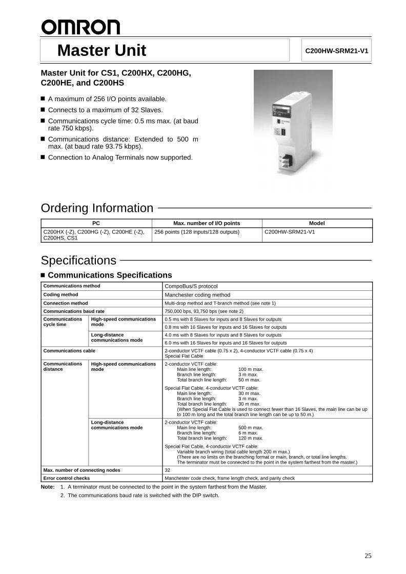
Master Unit C200HW-SRM21-V1
Master Unit for CS1, C200HX, C200HG,C200HE, and C200HS
A maximum of 256 I/O points available.
Connects to a maximum of 32 Slaves.
Communications cycle time: 0.5 ms max. (at baudrate 750 kbps).
Communications distance: Extended to 500 mmax. (at baud rate 93.75 kbps).
Connection to Analog Terminals now supported.
Ordering InformationPC Max. number of I/O points Model
C200HX (-Z), C200HG (-Z), C200HE (-Z),C200HS, CS1
256 points (128 inputs/128 outputs) C200HW-SRM21-V1
Specifications Communications Specifications
Communications method CompoBus/S protocol
Coding method Manchester coding method
Connection method Multi-drop method and T-branch method (see note 1)
Communications baud rate 750,000 bps, 93,750 bps (see note 2)
Communicationsl ti
High-speed communicationsd
0.5 ms with 8 Slaves for inputs and 8 Slaves for outputsCommunicationscycle time
High speed communicationsmode 0.8 ms with 16 Slaves for inputs and 16 Slaves for outputs
Long-distancei ti d
4.0 ms with 8 Slaves for inputs and 8 Slaves for outputsLong distancecommunications mode 6.0 ms with 16 Slaves for inputs and 16 Slaves for outputs
Communications cable 2-conductor VCTF cable (0.75 x 2), 4-conductor VCTF cable (0.75 x 4)Special Flat Cable
Communicationsdistance
High-speed communicationsmode
2-conductor VCTF cable:Main line length: 100 m max.Branch line length: 3 m max.Total branch line length: 50 m max.
Special Flat Cable, 4-conductor VCTF cable:Main line length: 30 m max.Branch line length: 3 m max.Total branch line length: 30 m max.(When Special Flat Cable is used to connect fewer than 16 Slaves, the main line can be upto 100 m long and the total branch line length can be up to 50 m.)
Long-distancecommunications mode
2-conductor VCTF cable:Main line length: 500 m max.Branch line length: 6 m max.Total branch line length: 120 m max.
Special Flat Cable, 4-conductor VCTF cable:Variable branch wiring (total cable length 200 m max.)(There are no limits on the branching format or main, branch, or total line lengths.The terminator must be connected to the point in the system farthest from the master.)
Max. number of connecting nodes 32
Error control checks Manchester code check, frame length check, and parity check
Note: 1. A terminator must be connected to the point in the system farthest from the Master.
2. The communications baud rate is switched with the DIP switch.
C200HW-SRM21-V1 C200HW-SRM21-V1
26
Unit SpecificationsCurrent consumption 150 mA max. at 5 VDC
Number of I/O points 256 points (128 inputs/128 outputs), 128 points (64 inputs/64 outputs) (switchable)
Number of occupied words 256 points: 20 words (8 input words/8 output words, 4 status data)128 points: 10 words (4 input words/4 output words, 2 status data)
PLC CS1, C200HX (-ZE), C200HG (-ZE), C200HE (-ZE), C200HS
Number ofM t U it
C200HE 128 points: 10, 256 points: 5Number ofMaster Unitsmountable C200HG-CPU33/43 128 points: 10, 256 points: 5mountable
C200HG-CPU53/63 128 points: 16, 256 points: 8
C200HX-CPU34/44 128 points: 10, 256 points: 5
C200HX-CPU54/64 128 points: 16, 256 points: 8
C200HS 128 points: 10, 256 points: 5
CS1 128 points: 16, 256 points: 8
Number of points per node number 8 points
Max. number of Slaves per Master 32
Status data Communications Error Flag and Active Slave Node (see note)
Weight 200 g max.
Approved standards UL 508 (E95399), CSA C22.2 No. 142 (LR51460)
Note: These flags use the AR area.
RatingsThe ratings of the Unit are the same as those of the CS1, C200HX, C200HG, C200HE, and C200HS.
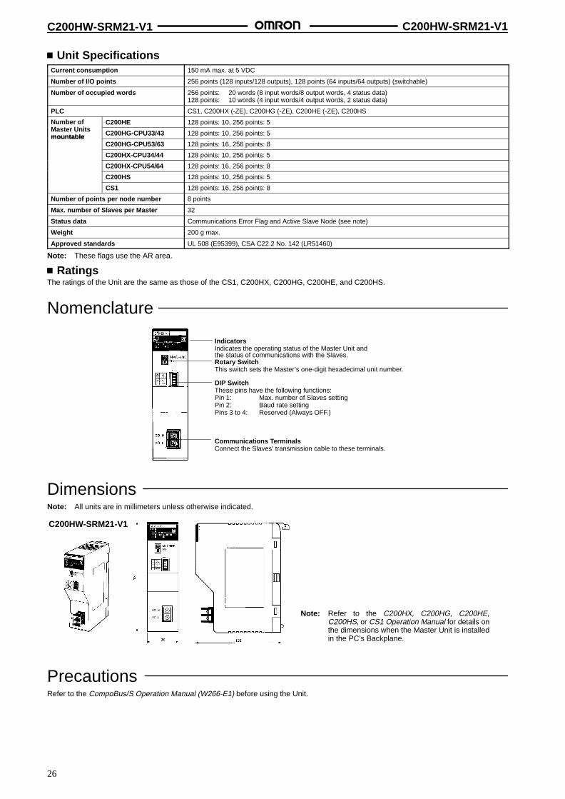
Nomenclature
IndicatorsIndicates the operating status of the Master Unit andthe status of communications with the Slaves.Rotary SwitchThis switch sets the Master’s one-digit hexadecimal unit number.
DIP SwitchThese pins have the following functions:Pin 1: Max. number of Slaves settingPin 2: Baud rate settingPins 3 to 4: Reserved (Always OFF.)
Communications TerminalsConnect the Slaves’ transmission cable to these terminals.
DimensionsNote: All units are in millimeters unless otherwise indicated.
C200HW-SRM21-V1
Note: Refer to the C200HX, C200HG, C200HE,C200HS, or CS1 Operation Manual for details onthe dimensions when the Master Unit is installedin the PC’s Backplane.
PrecautionsRefer to the CompoBus/S Operation Manual (W266-E1) before using the Unit.

27
Master Unit CQM1-SRM21-V1
Master Unit for CQM1/CQM1H
A maximum of 128 I/O points available (Possible toset 32, 64, or 128 I/O points).
Connects to a maximum of 16/32 Slaves.
Communications cycle time: 0.5 ms max. (at baudrate 750 kbps).
Communications distance: Extended to 500 mmax. (at baud rate 93.75 kbps).
Connection to Analog Terminals now supported.
Ordering InformationPLC Max. number of I/O points Model
CQM1-series PLC 128 points (64 inputs/64 outputs) CQM1-SRM21-V1
Specifications Communications Specifications
Communications method CompoBus/S protocol
Coding method Manchester coding method
Connection method Multi-drop method and T-branch method (see note 1)
Communications baud rate 750,000 bps, 93,750 bps (see note 2)
Communicationscycle time
High-speedcomm nications
0.5 ms with 8 Slaves for inputs and 8 Slaves for outputscycle time communications
mode 0.8 ms with 16 Slaves for inputs and 16 Slaves for outputs
Long-distancecomm nications
4.0 ms with 8 Slaves for inputs and 8 Slaves for outputscommunicationsmode 6.0 ms with 16 Slaves for inputs and 16 Slaves for outputs
Communications cable 2-conductor VCTF cable (0.75 x 2), 4-conductor VCTF cable (0.75 x 4)Special Flat Cable
Communicationsdistance
High-speedcommunicationsmode
2-conductor VCTF cable:Main line length: 100 m max.Branch line length: 3 m max.Total branch line length: 50 m max.
Special Flat Cable, 4-conductor VCTF cable:Main line length: 30 m max.Branch line length: 3 m max.Total branch line length: 30 m max.(When Special Flat Cable is used to connect fewer than 16 Slaves, the main line can be up to 100 mlong and the total branch line length can be up to 50 m.)
Long-distancecommunicationsmode
2-conductor VCTF cable:Main line length: 500 m max.Branch line length: 6 m max.Total branch line length: 120 m max.
Special Flat Cable, 4-conductor VCTF cable:Variable branch wiring (total cable length 200 m max.)(There are no limits on the branching format or main, branch, or total line lengths.The terminator must be connected to the point in the system farthest from the master.)
Max. number of connecting nodes 32
Error control checks Manchester code check, frame length check, and parity check
Note: 1. A terminator must be connected to the point in the system farthest from the Master.
2. The communications baud rate is switched with the DIP switch.
CQM1-SRM21-V1 CQM1-SRM21-V1
28
Unit SpecificationsCurrent consumption 180 mA max. at 5 VDC
Number of I/O points 128 points (64 inputs/64 outputs), 64 points (32 inputs/32 outputs),32 points (16 inputs/16 outputs) (switchable)
Number of occupied words 128 points: 4 input words/4 output words64 points: 2 input words/2 output words32 points: 1 input word/1 output word
PC 128 points: CQM1-CPU41-EV1/CPU42-EV1/CPU43-EV1/CPU44-EV164 points: CQM1-CPU11-E/CPU21-E/CPU41-EV1/CPU42-EV1/CPU43-EV1/CPU44-EV132 points: CQM1-CPU11-E/CPU21-E/CPU41-EV1/CPU42-EV1/CPU43-EV1/CPU44-EV1
Number of points per node number 4/8 points (switchable)
Max. number of Slaves per Master 32 (4 points per node number)
Status data Alarm terminal output
Weight 200 g max.
Approved standards UL 508 (E95399), CSA C22.2 No. 142 (LR51460)
Alarm Output SpecificationsMaximum switching capacity 2 A at 24 VDC
Minimum switching capacity 10 mA at 5 VDC
Relay G6D-1A
Minimum ON time 100 ms
Circuit configuration
2 A at 24 VDC max.
Internalcircuit
CQM1-SRM21-V1
RatingsThe ratings of the Unit are the same as those for the CQM1.
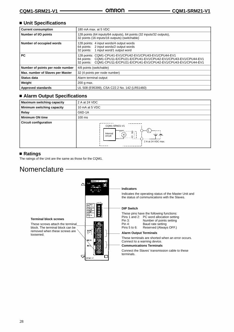
Nomenclature
Indicators
Indicates the operating status of the Master Unit andthe status of communications with the Slaves.
DIP Switch
These pins have the following functions:Pins 1 and 2: PC word allocation settingPin 3: Number of points settingPin 4: Baud rate settingPins 5 to 6: Reserved (Always OFF.)
Alarm Output Terminals
These terminals are shorted when an error occurs.Connect to a warning device.Communications Terminals
Connect the Slaves’ transmission cable to theseterminals.
Terminal block screws
These screws attach the terminalblock. The terminal block can beremoved when these screws areloosened.
CQM1-SRM21-V1 CQM1-SRM21-V1
29
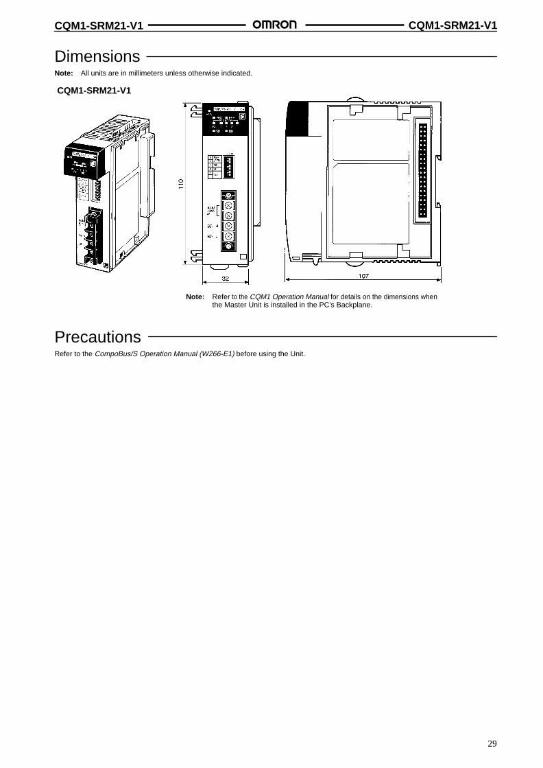
DimensionsNote: All units are in millimeters unless otherwise indicated.
CQM1-SRM21-V1
Note: Refer to the CQM1 Operation Manual for details on the dimensions whenthe Master Unit is installed in the PC’s Backplane.
PrecautionsRefer to the CompoBus/S Operation Manual (W266-E1) before using the Unit.

30
SYSMAC Boards with CompoBus/S Master C200PC-ISA3-SRM
Intelligent Computer Board thatIntegrates SYSMAC C200HX/HG/HE andCompoBus/S Master FunctionsEquipped with Backup Power SupplySystem
Can be mounted to an ISA bus, the standard bus forIBM compatible computers, thus contributing to thedownsizing of installations using computers.
Communications between the SYSMAC Board andthe computer are performed via an ISA bus,enabling a communications speed much higherthan with RS-232C communications.
Incorporates CompoBus/S communications func-tions. Simply connect a CompoBus/S Slave toenable distributed control of I/O in remote locations.
A power supply sub-board is also available. Thismakes it possible to provide power externally, andallows control to be continued even when thecomputer power supply is interrupted.
Data settings at CompoBus/S Slaves are reflectedautomatically.
Enables communications at a maximum distanceof 500 m (at a baud rate of 93.75 kbps).
Conforms to EC Directives.
Ordering InformationPLC Max. number of I/O points Model
C200HG-CPU43 256 points (128 inputs/128 outputs) C200PC-ISA03-SRM
C200HX-CPU64
( )
C200PC-ISA13-SRM

C200PC-ISA3-SRM C200PC-ISA3-SRM
31
Specifications Communications Specifications
Communications method CompoBus/S protocol
Coding method Manchester coding method
Connection method Multi-drop method and T-branch method (see note)
Communications baud rate 750,000 bps, 93,750 bps
Communications cycle time 0.5 ms with 8 Slaves for inputs and 8 Slaves for outputs0.8 ms with 16 Slaves for inputs and 16 Slaves for outputs
Communications cable 2-conductor VCTF cable (0.75 x 2), 4-conductor VCTF cable (0.75 x 4)Special Flat Cable
Communicationsdistance
High-speedcommunicationsmode
2-conductor VCTF cable:Main line length: 100 m max.Branch line length: 3 m max.Total branch line length: 50 m max.
Special Flat Cable, 4-conductor VCTF cable:Main line length: 30 m max.Branch line length: 3 m max.Total branch line length: 30 m max.(When Special Flat Cable is used to connect fewer than 16 Slaves, the main line can beup to 100 m long and the total branch line length can be up to 50 m.)
Long-distancecommunicationsmode
2-conductor VCTF cable:Main line length: 500 m max.Branch line length: 6 m max.Total branch line length: 120 m max.
Special Flat Cable, 4-conductor VCTF cable:Variable branch wiring (total cable length 200 m max.)(There are no limits on the branching format or main, branch, or total line lengths.The terminator must be connected to the point in the system farthest from the master.)
Max. number of connecting nodes 32
Error control checks Manchester code check, frame length check, and parity check
Note: A terminator must be connected to the point in the system farthest from the Master.
Unit SpecificationsPower supply voltage 4.875 to 5.25 VDC
Current consumption 0.5 A max. (see note 1)
Number of I/O points 256 points (128 inputs/128 outputs), 128 points (64 inputs/64 outputs), (switchable)
Number of occupied words 256 points: 20 words (8 input words, 8 output words, and 4 status data words) (see note 2)128 points: 10 words (4 input words, 4 output words, and 2 status data words)
Number of points per node number 8 points
Max. number of Slaves per Master 32
Status data Communications Error Flag and Active Slave Node (see note 2)
Weight 350 g max.
Note: 1. The current consumption will be 0.8 A max. if the Programming Console is connected through the optional Expansion Board.
2. The occupied words are in the IR area.

32
I/O Link Unit CPM2C-SRT21
I/O Link Unit for CPM2C
Operates as a Slave of the CompoBus/S MasterUnit.
Exchanges eight inputs and eight outputs with theMaster.
Bears the CE marking.
Ordering InformationCompoBus I/O Link Unit
Name Specifications Model
CompoBus/S I/O Link Unit Number of points for I/O links:8 inputs and 8 outputs
CPM2C-SRT21
Application Examples Conveyor Line
Processing speed can be increased and system setup labor reduced by creating a distributed system with a CPM2C at each conveyor.
CompoBus/S Master Unit(or SRM1 CompoBus/SMaster Control Unit)
CS1C200CQM1(H)CPM2C-SSRM1
CPM2CCPU Unit
Connectable to 16 Units max.(Eight CQM1-SRM21-V1 Units max.)
CompoBus/SI/O LInk Unit(CPM2C-SRT21)
Special Flat Cable or VCTF cable
SpecificationsItem CPM2C-SRT21
Master/Slave CompoBus/S Slave
Number of I/O points 8 inputs and 8 outputs
Number of words occupied inCPM2C’s I/O memory
1 input word and 1 output word (allocated in the same way as for other Expansion Units)
Node address setting DIP switch
Power consumption 1 W
Weight 150 g
Note: For details of CPM2C PLCs, refer to the CPM2C catalog (Cat. No. P049).

CPM2C-SRT21 CPM2C-SRT21
33
DimensionsCPM2C-SRT21
Installation Number of I/O Units Connectable
Up to 5 Expansion Units can be connected to CPM2C PLCs. There are, however, only 9 input words and 9 output words that can be allocated toExpansion I/O Units: words IR 001 to IR 009 for inputs (the CPU Unit’s inputs are allocated to IR 001) and words IR 011 to IR 019 for outputs (theCPU Unit’s outputs are allocated to IR 010). Use Expansion I/O Units within these ranges. I/O words are allocated from the leftmost Unit.
Example
5 Units max.
CPU Unit

34
I/O Link Unit CPM1A-SRT21
I/O Link Unit for CPM2A/CPM1A
Operates as a Slave of the CompoBus/S MasterUnit.
Exchanges eight inputs and eight outputs with theMaster.
Approved by UL and CSA standards, and bears theCE marking.
SpecificationsMaster/Slave CompoBus/S Slave
Number of I/O points 8 inputs and 8 outputs
Number of words occupied in CPM2A’sI/O memory
1 input word and 1 output word (allocated in the same way as for other Expansion Units)
Node address setting DIP switch
Note: For details of CPM1A PLCs, refer to the CPM1A catalog (Cat. No. P039). For details of CPM2A PLCs, refer to the CPM2A catalog (Cat. No. P049).
DimensionsNote: All units are in millimeters unless otherwise indicated.
CPM1A-SRT21
Installation Connection Examples
CompoBus/S Master Unit or SRM1CompoBus/S Master Control Unit CPM1A or CPM2A CPU Unit
CPM1A-SRT21CompoBus/S I/O Link Unit
CS1C200H
CQM1SRM1CPM2C-S Special Flat Cable or VCTF cable Connectable to 16 Units max.
(Eight CQM1-SRM21-V1 Units max.)
Note: A single CompoBus/S I/O Link Unit together with a maximum of two other Expansion I/O Units can be connected to the CPM1A or CPM2A CPU Unit.

35
Transistor Remote I/O Terminals SRT2-ID/OD(-1)
Long-distance CommunicationsSupported by SRT2 Models(Long-distance/High-speedCommunications Selection)
Ultra-compact at 80 x 48 x 50 (W x H x D) mm for4-point and 8-point terminals and 105 x 48 x 50 (W xH x D) mm for 16-point terminals.
Two independent power supplies can be usedbecause the I/O terminals are insulated from theinternal circuits.
DIN track mounting and screw mounting are bothsupported.
Ordering InformationI/O classification Internal I/O circuit
commonI/O points Rated voltage I/O rated voltage Model
Input NPN (+ common) 4 24 VDC 24 VDC SRT2-ID04
PNP (– common) SRT2-ID04-1Output NPN (– common) SRT2-OD04
PNP (+ common) SRT2-OD04-1
Input NPN (+ common) 8 SRT2-ID08
PNP (– common) SRT2-ID08-1
Output NPN (– common) SRT2-OD08
PNP (+ common) SRT2-OD08-1
Input NPN (+ common) 16 SRT2-ID16
PNP (– common) SRT2-ID16-1
Output NPN (– common) SRT2-OD16
PNP (+ common) SRT2-OD16-1
Note: For more details about connections supported by the Master Unit, refer to page 25.
SpecificationsRatings
Inputs
Input current 6 mA max./point
ON delay time 1.5 ms max.
OFF delay time 1.5 ms max.
ON voltage 15 VDC min. between each input terminal and V
OFF voltage 5 VDC max. between each input terminal and V
OFF current 1 mA max.
Insulation method Photocoupler
Input indicators LED (yellow)

SRT2-ID/OD(-1) SRT2-ID/OD(-1)
36
Outputs
Rated output current 0.3 A/point
Residual voltage 0.6 V max.
Leakage current 0.1 mA max.
Insulation method Photocoupler
Output indicators LED (yellow)
CharacteristicsCommunications power supply voltage 14 to 26.4 VDC
I/O power supply voltage 24 VDC +10%/–15%
I/O power supply current 1 A max.
Current consumption (see note) 50 mA max. at 24 VDC
Connection method Multi-drop method and T-branch method
Connecting Units 4-point and 8-point Terminals: 16 Input Terminals and 16 Output Terminals per Master
16-point Terminals: 8 Input Terminals and 8 Output Terminals per Master
Dielectric strength 500 VAC for 1 min (1-mA sensing current between insulated circuits)
Noise immunity Conforms to IEC61000-4-4, 2 kV (power lines)
Vibration resistance 10 to 55 Hz, 1.5-mm double amplitude
Shock resistance Malfunction: 200 m/s2
Destruction: 300 m/s2
Mounting strength No damage when 50 N pull load was applied for 10 s in all directions
Terminal strength No damage when 50 N pull load was applied for 10 s
Screw tightening torque 0.6 to 1.18 N m
Ambient temperature Operating: 0°C to 55°C (with no icing or condensation)Storage: –20°C to 65°C (with no icing or condensation)
Ambient humidity Operating: 35% to 85%
Weight 4-point and 8-point Terminals: 80 g max.16-point Terminals: 110 g max.
Approved standards (4/8 points) UL 508, CSA C22.2 No. 14
Note: The above current consumption is the value with all 4 and 8 and 16 points turned ON excluding the current consumption of the externalsensor connected to the input Remote Terminal and the current consumption of the load connected to the output Remote Terminal.
Nomenclature
I/O TerminalsI/O Power Supply TerminalsConnect 24-VDC power supplyCommunications Power Supply TerminalsConnect 14- to 26.4-VDC power supply.CompoBus/S TerminalConnect the CompoBus/S communications cable.DIP Switch
Used for node number setting and holding or clearing outputs for communications error.Refer to the Compobus/S Operation Manual (W266-E1) for details on DIP switch settings.
Baud rate setting
0 to 7ERRCOMMPWR
Node Number Settings
Output HOLD/CLEAR settings (Output Terminals only)
Screw mounting hole
SRT2-ID/OD(-1) SRT2-ID/OD(-1)
37
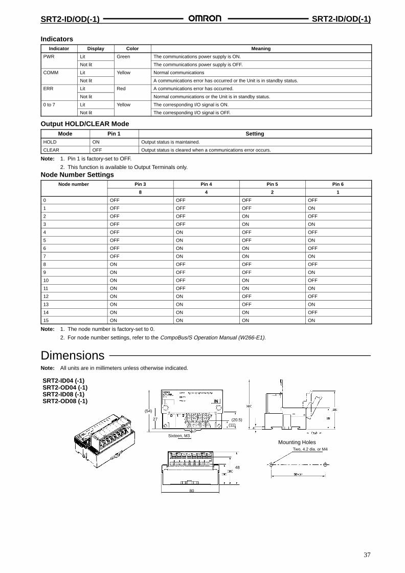
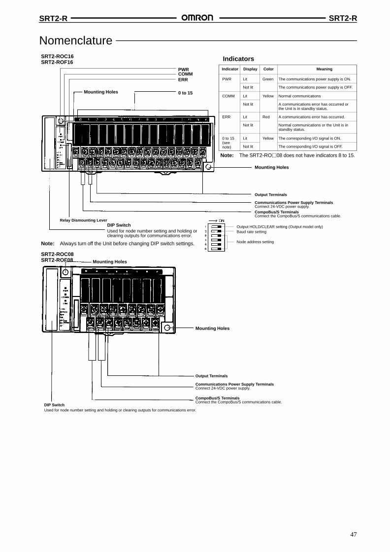
IndicatorsIndicator Display Color Meaning
PWR Lit Green The communications power supply is ON.
Not lit The communications power supply is OFF.
COMM Lit Yellow Normal communications
Not lit A communications error has occurred or the Unit is in standby status.
ERR Lit Red A communications error has occurred.
Not lit Normal communications or the Unit is in standby status.
0 to 7 Lit Yellow The corresponding I/O signal is ON.
Not lit The corresponding I/O signal is OFF.
Output HOLD/CLEAR ModeMode Pin 1 Setting
HOLD ON Output status is maintained.
CLEAR OFF Output status is cleared when a communications error occurs.
Note: 1. Pin 1 is factory-set to OFF.
2. This function is available to Output Terminals only.
Node Number SettingsNode number Pin 3 Pin 4 Pin 5 Pin 6
8 4 2 1
0 OFF OFF OFF OFF
1 OFF OFF OFF ON
2 OFF OFF ON OFF
3 OFF OFF ON ON
4 OFF ON OFF OFF
5 OFF ON OFF ON
6 OFF ON ON OFF
7 OFF ON ON ON
8 ON OFF OFF OFF
9 ON OFF OFF ON
10 ON OFF ON OFF
11 ON OFF ON ON
12 ON ON OFF OFF
13 ON ON OFF ON
14 ON ON ON OFF
15 ON ON ON ON
Note: 1. The node number is factory-set to 0.
2. For node number settings, refer to the CompoBus/S Operation Manual (W266-E1).
DimensionsNote: All units are in millimeters unless otherwise indicated.
SRT2-ID04 (-1)SRT2-OD04 (-1)SRT2-ID08 (-1)SRT2-OD08 (-1)
(54)
27
80
48
Two, 4.2 dia. or M4
Sixteen, M3
Mounting Holes
(20.5)(11)

SRT2-ID/OD(-1) SRT2-ID/OD(-1)
38
SRT2-ID16 (-1)SRT2-OD16 (-1)
48
Two, 4.2 dia. or M4
(50)
Mounting Holes
(54)
27
50
(20.5)(11)
105
Twenty-two, M3
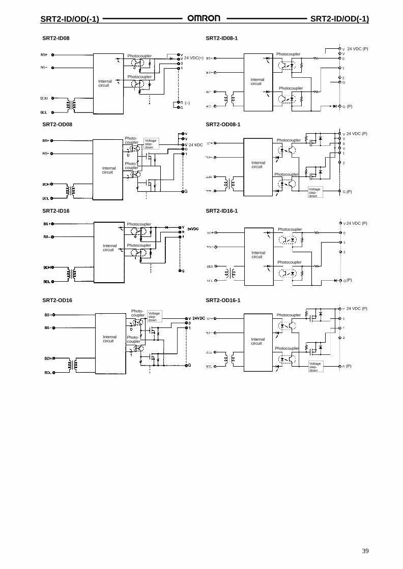
Installation Internal Circuit Configuration
SRT2-ID04 SRT2-ID04-1
Photocoupler
PhotocouplerInternalcircuit
Internalcircuit
24 VDC(+)Photocoupler
Photocoupler(–)
SRT2-OD04
Internalcircuit
24 VDC
Photo-coupler
Photo-coupler
Voltagestep-down
SRT2-OD04-1
Internalcircuit
Photocoupler
Photocoup-ler
24 VDC (P)
(P)
24 VDC (P)
(P)Voltagestep-down
VV
V1G0
2G
G
VV
V1V0
2
G
SRT2-ID/OD(-1) SRT2-ID/OD(-1)
39
SRT2-OD08-1
Internalcircuit
Photocoupler
Photocoupler
SRT2-ID08 SRT2-ID08-1
Photocoupler
Photocoupler
Internalcircuit
24 VDC(+)
Internalcircuit
Photocoupler
Photocoupler
(–)
SRT2-OD08
Internalcircuit
24 VDC
Photo-coupler
Photo-coupler Voltage
step-down
SRT2-ID16
Photocoupler
PhotocouplerInternalcircuit
SRT2-ID16-1
Internalcircuit
Photocoupler
Photocoupler
Internalcircuit
SRT2-OD16
Photo-coupler
Photo-coupler
Voltagestep-down
SRT2-OD16-1
Internalcircuit
Photocoupler
Photocoupler
Voltagestep-down
24 VDC (P)
24 VDC (P)
(P)Voltagestep-down
(P)
24 VDC (P)
(P)
24 VDC (P)
(P)
VV
1
0
2G
G
VV
1
0
2
G
V
V
1
0
2
G
SRT2-ID/OD(-1) SRT2-ID/OD(-1)
40
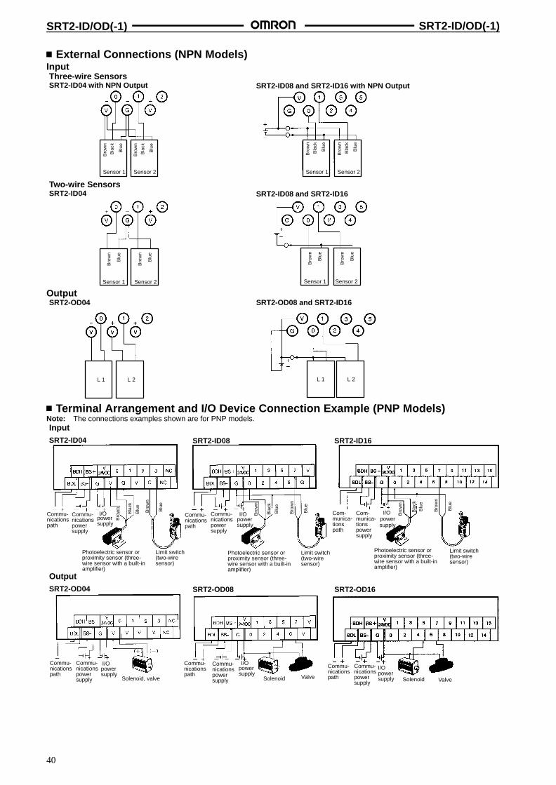
External Connections (NPN Models)Input
Sensor 1
Blu
e
Bro
wn
Bla
ck
Sensor 2
Blu
e
Bro
wn
Bla
ck
Sensor 1
Blu
e
Bro
wn
Bla
ck
Sensor 2
Blu
e
Bro
wn
Bla
ck
Three-wire SensorsSRT2-ID04 with NPN Output SRT2-ID08 and SRT2-ID16 with NPN Output
Two-wire SensorsSRT2-ID04 SRT2-ID08 and SRT2-ID16
Sensor 1
Blu
e
Bro
wn
Sensor 2
Blu
e
Bro
wn
Sensor 1
Blu
e
Bro
wn
Sensor 2
Blu
e
Bro
wn
OutputSRT2-OD04 SRT2-OD08 and SRT2-ID16
L 1 L 2L 1 L 2
Terminal Arrangement and I/O Device Connection Example (PNP Models)Note: The connections examples shown are for PNP models.InputSRT2-ID04 SRT2-ID08
OutputSRT2-OD04 SRT2-OD08
Blu
e
Bro
wn
Blu
e
Bro
wn
Blu
e
Bro
wn
Bro
wn
Blu
e
Commu-nicationspath
Commu-nicationspowersupply
powersupply
powersupply
Commu-nicationspath
Commu-nicationspowersupply
Commu-nicationspath
Commu-nicationspowersupply
powersupply
Photoelectric sensor orproximity sensor (three-wire sensor with a built-inamplifier)
Limit switch(two-wiresensor)
Solenoid, valve Solenoid
I/O Commu-nicationspath
Commu-nicationspowersupply
Photoelectric sensor orproximity sensor (three-wire sensor with a built-inamplifier)
Limit switch(two-wiresensor)
Bla
ck
Bla
ck
SRT2-ID16
SRT2-OD16
Com-munica-tionspath
Com-munica-tionspowersupply
I/Opowersupply
Photoelectric sensor orproximity sensor (three-wire sensor with a built-inamplifier)
Limit switch(two-wiresensor)
I/Opowersupply
Commu-nicationspath
Commu-nicationspowersupply
SolenoidValve Valve
powersupply
I/O
Blu
e
Bro
wn
Blu
e
Bro
wn
Bla
ck
I/O I/O

SRT2-ID/OD(-1) SRT2-ID/OD(-1)
41
External Connections (PNP Models)InputThree-wire SensorsSRT2-ID04-1 with NPN Output SRT2-ID08-1 and SRT2-ID16-1 with NPN Output
Two-wire SensorsSRT2-ID04-1 SRT2-ID08-1 and SRT2-ID16-1
Sensor 1
Blu
e
Bro
wn
Bla
ck
Sensor 2
Blu
e
Bro
wn
Bla
ck
Sensor 1
Blu
e
Bro
wn
Bla
ck
Sensor 2
Blu
e
Bro
wn
Bla
ck
Sensor 1
Blu
e
Bro
wn
Sensor 2
Blu
e
Bro
wn
Sensor 1
Blu
e
Bro
wn
Sensor 2
Blu
e
Bro
wn
OutputSRT2-OD04-1 SRT2-OD08-1 and SRT2-ID16-1
L 1 L 2L 1 L 2
Terminal Arrangement and I/O Device Connection Example (PNP Models)Note: The connections examples shown are for NPN models.InputSRT2-ID04-1 SRT2-ID08-1
OutputSRT2-OD04-1 SRT2-OD08-1
Blu
e
Bro
wn B
lue
Bro
wn
Blu
e
Bro
wn
Bro
wn
Blu
e
Commu-nicationspath
Commu-nicationspowersupply
powersupply
powersupply
Commu-nicationspath
Commu-nicationspowersupply
Commu-nicationspath
Commu-nicationspowersupply
powersupply
Photoelectric sensor or prox-imity sensor (three-wire sensorwith a built-in amplifier)
Limit switch (two-wire sensor)
Solenoid, valve Solenoid
I/O Commu-nicationspath
Commu-nicationspowersupply
Photoelectric sensor or prox-imity sensor (three-wire sen-sor with a built-in amplifier)
Limit switch (two-wire sensor)
Bla
ck
Bla
ck
SRT2-ID16-1
SRT2-OD16-1
Com-munica-tionspath
Com-munica-tionspowersupply
I/Opowersupply
Photoelectric sensor or prox-imity sensor (three-wire sen-sor with a built-in amplifier)
Limit switch (two-wire sensor)
I/Opowersupply
Commu-nicationspath
Commu-nicationspowersupply SolenoidValve Valve
powersupply
I/O
Blu
e
Bro
wn
Blu
e
Bro
wn
Bla
ck
I/O I/O
PrecautionsRefer to the CompoBus/S Operation Manual (W266-E1) before using the Unit.
42
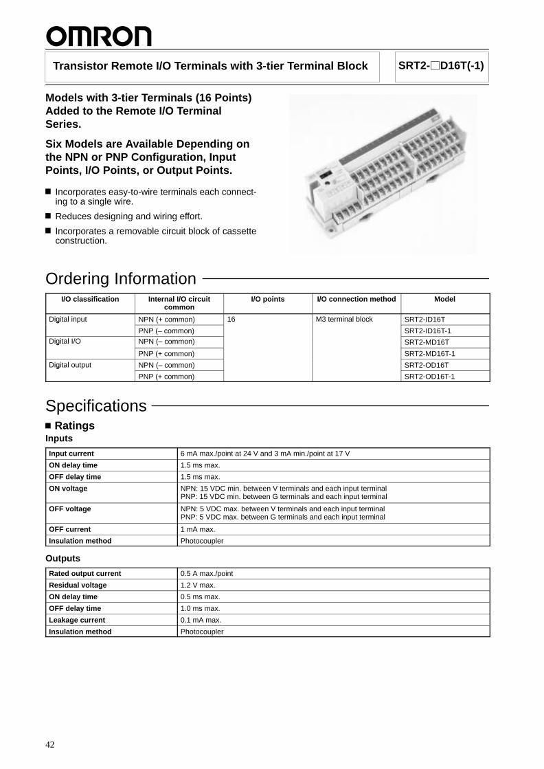
Transistor Remote I/O Terminals with 3-tier Terminal Block SRT2-D16T(-1)
Models with 3-tier Terminals (16 Points)Added to the Remote I/O TerminalSeries.
Six Models are Available Depending onthe NPN or PNP Configuration, InputPoints, I/O Points, or Output Points.
Incorporates easy-to-wire terminals each connect-ing to a single wire.
Reduces designing and wiring effort.
Incorporates a removable circuit block of cassetteconstruction.
Ordering InformationI/O classification Internal I/O circuit
commonI/O points I/O connection method Model
Digital input NPN (+ common) 16 M3 terminal block SRT2-ID16Tg
PNP (– common) SRT2-ID16T-1Digital I/O NPN (– common) SRT2-MD16Tg
PNP (+ common) SRT2-MD16T-1
Digital output NPN (– common) SRT2-OD16Tg
PNP (+ common) SRT2-OD16T-1
SpecificationsRatings
Inputs
Input current 6 mA max./point at 24 V and 3 mA min./point at 17 V
ON delay time 1.5 ms max.
OFF delay time 1.5 ms max.
ON voltage NPN: 15 VDC min. between V terminals and each input terminalPNP: 15 VDC min. between G terminals and each input terminal
OFF voltage NPN: 5 VDC max. between V terminals and each input terminalPNP: 5 VDC max. between G terminals and each input terminal
OFF current 1 mA max.
Insulation method Photocoupler
Outputs
Rated output current 0.5 A max./point
Residual voltage 1.2 V max.
ON delay time 0.5 ms max.
OFF delay time 1.0 ms max.
Leakage current 0.1 mA max.
Insulation method Photocoupler
SRT2-D16T(-1) SRT2-D16T(-1)
43
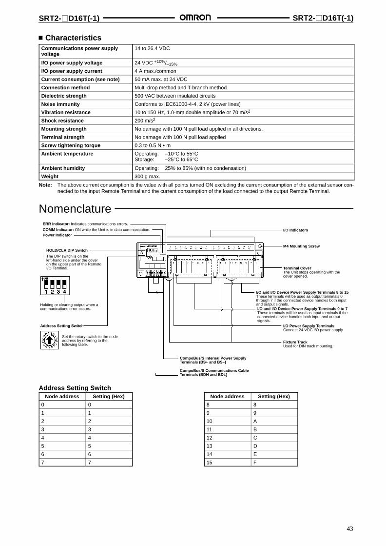
CharacteristicsCommunications power supplyvoltage
14 to 26.4 VDC
I/O power supply voltage 24 VDC +10%/–15%
I/O power supply current 4 A max./common
Current consumption (see note) 50 mA max. at 24 VDC
Connection method Multi-drop method and T-branch method
Dielectric strength 500 VAC between insulated circuits
Noise immunity Conforms to IEC61000-4-4, 2 kV (power lines)
Vibration resistance 10 to 150 Hz, 1.0-mm double amplitude or 70 m/s2
Shock resistance 200 m/s2
Mounting strength No damage with 100 N pull load applied in all directions.
Terminal strength No damage with 100 N pull load applied
Screw tightening torque 0.3 to 0.5 N m
Ambient temperature Operating: –10°C to 55°CStorage: –25°C to 65°C
Ambient humidity Operating: 25% to 85% (with no condensation)
Weight 300 g max.
Note: The above current consumption is the value with all points turned ON excluding the current consumption of the external sensor con-nected to the input Remote Terminal and the current consumption of the load connected to the output Remote Terminal.
NomenclatureERR Indicator: Indicates communications errors.
COMM Indicator: ON while the Unit is in data communication.Power Indicator
HOLD/CLR DIP Switch
The DIP switch is on theleft-hand side under the coveron the upper part of the RemoteI/O Terminal.
Holding or clearing output when acommunications error occurs.
Address Setting Switch
Set the rotary switch to the nodeaddress by referring to thefollowing table.
I/O Indicators
M4 Mounting Screw
Terminal CoverThe Unit stops operating with thecover opened.
I/O and I/O Device Power Supply Terminals 8 to 15These terminals will be used as output terminals 0through 7 if the connected device handles both inputand output signals.I/O and I/O Device Power Supply Terminals 0 to 7These terminals will be used as input terminals if theconnected device handles both input and outputsignals.
I/O Power Supply TerminalsConnect 24-VDC I/O power supply
Fixture TrackUsed for DIN track mounting.
CompoBus/S Internal Power SupplyTerminals (BS+ and BS–)
CompoBus/S Communications CableTerminals (BDH and BDL)
Address Setting SwitchNode address Setting (Hex)
0 0
1 1
2 2
3 3
4 4
5 5
6 6
7 7
Node address Setting (Hex)
8 8
9 9
10 A
11 B
12 C
13 D
14 E
15 F
SRT2-D16T(-1) SRT2-D16T(-1)
44
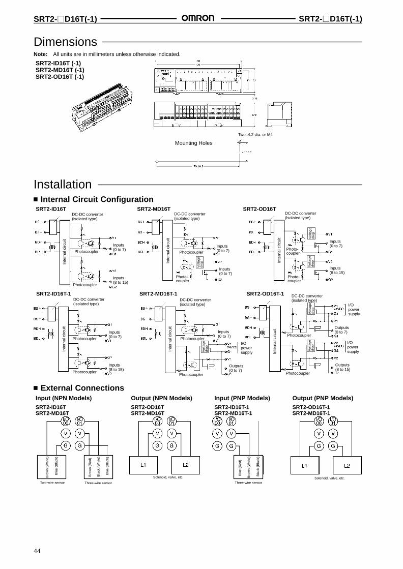
DimensionsNote: All units are in millimeters unless otherwise indicated.
SRT2-ID16T (-1)SRT2-MD16T (-1)SRT2-OD16T (-1)
Mounting Holes
Two, 4.2 dia. or M4
Installation Internal Circuit Configuration
SRT2-ID16T SRT2-MD16T
SRT2-ID16T-1 SRT2-MD16T-1
SRT2-OD16T
SRT2-OD16T-1
DC-DC converter(isolated type)
Photocoupler
Photocoupler
Inputs(0 to 7)
Inputs(8 to 15)
DC-DC converter(isolated type)
Photocoupler
Photo-coupler
Inputs(0 to 7)
Inputs(0 to 7)
DC-DC converter(isolated type)
Photo-coupler
Photo-coupler
Inputs(0 to 7)
Inputs(8 to 15)
DC-DC converter(isolated type)
Photocoupler
Photocoupler
Inputs(0 to 7)
Inputs(8 to 15)
DC-DC converter(isolated type)
Photocoupler
Photocoupler
Inputs(0 to 7)
Outputs(0 to 7)
DC-DC converter(isolated type)
Photocoupler
Photocoupler
Outputs(0 to 7)
Outputs(8 to 15)
I/Opowersupply
I/Opowersupply
I/Opowersupply
Inte
rnal
circ
uit
Inte
rnal
circ
uit
Inte
rnal
circ
uit
Inte
rnal
circ
uit
Inte
rnal
circ
uit
Inte
rnal
circ
uit
Vol
tage
drop
Vol
tage
drop
Vol
tage
drop
Vol
tage
drop
Vol
tage
drop
Vol
tage
drop
External ConnectionsInput (NPN Models)SRT2-ID16TSRT2-MD16T
Output (NPN Models)SRT2-OD16TSRT2-MD16T
Input (PNP Models)SRT2-ID16T-1SRT2-MD16T-1
Output (PNP Models)SRT2-OD16T-1SRT2-MD16T-1
Two-wire sensor Three-wire sensor Three-wire sensor
Solenoid, valve, etc. Solenoid, valve, etc.
Blu
e (B
lack
)
Bro
wn
(Whi
te)
Blu
e (B
lack
)
Bro
wn
(Red
)
Bla
ck (
Whi
te)
Bla
ck (
Bla
ck)
Blu
e (R
ed)
Bro
wn
(Whi
te)
45
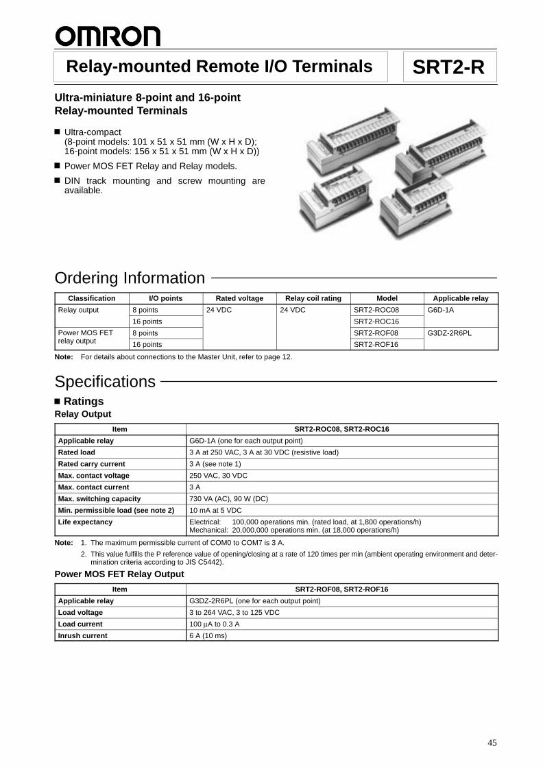
Relay-mounted Remote I/O Terminals SRT2-RUltra-miniature 8-point and 16-pointRelay-mounted Terminals
Ultra-compact(8-point models: 101 x 51 x 51 mm (W x H x D);16-point models: 156 x 51 x 51 mm (W x H x D))
Power MOS FET Relay and Relay models.
DIN track mounting and screw mounting areavailable.
Ordering InformationClassification I/O points Rated voltage Relay coil rating Model Applicable relay
Relay output 8 points 24 VDC 24 VDC SRT2-ROC08 G6D-1A
16 points SRT2-ROC16
Power MOS FETl t t
8 points SRT2-ROF08 G3DZ-2R6PLrelay output 16 points SRT2-ROF16
Note: For details about connections to the Master Unit, refer to page 12.
SpecificationsRatings
Relay Output
Item SRT2-ROC08, SRT2-ROC16
Applicable relay G6D-1A (one for each output point)
Rated load 3 A at 250 VAC, 3 A at 30 VDC (resistive load)
Rated carry current 3 A (see note 1)
Max. contact voltage 250 VAC, 30 VDC
Max. contact current 3 A
Max. switching capacity 730 VA (AC), 90 W (DC)
Min. permissible load (see note 2) 10 mA at 5 VDC
Life expectancy Electrical: 100,000 operations min. (rated load, at 1,800 operations/h)Mechanical: 20,000,000 operations min. (at 18,000 operations/h)
Note: 1. The maximum permissible current of COM0 to COM7 is 3 A.
2. This value fulfills the P reference value of opening/closing at a rate of 120 times per min (ambient operating environment and deter-mination criteria according to JIS C5442).
Power MOS FET Relay Output
Item SRT2-ROF08, SRT2-ROF16
Applicable relay G3DZ-2R6PL (one for each output point)
Load voltage 3 to 264 VAC, 3 to 125 VDC
Load current 100 µA to 0.3 A
Inrush current 6 A (10 ms)
SRT2-R SRT2-R
46
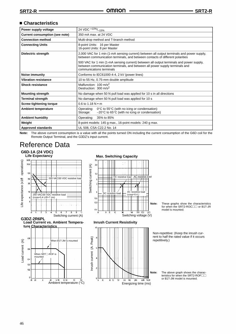
CharacteristicsPower supply voltage 24 VDC +10%/–15%
Current consumption (see note) 350 mA max. at 24 VDC
Connection method Multi-drop method and T-branch method
Connecting Units 8-point Units: 16 per Master16-point Units: 8 per Master
Dielectric strength 2,000 VAC for 1 min (1-mA sensing current) between all output terminals and power supply,between communication terminals, and between contacts of different polarities
500 VAC for 1 min (1-mA sensing current) between all output terminals and power supply,between communication terminals, and between all power supply terminals andcommunications terminals
Noise immunity Conforms to IEC61000-4-4, 2 kV (power lines)
Vibration resistance 10 to 55 Hz, 0.75-mm double amplitude
Shock resistance Malfunction: 100 m/s2
Destruction: 300 m/s2
Mounting strength No damage when 50 N pull load was applied for 10 s in all directions
Terminal strength No damage when 50 N pull load was applied for 10 s
Screw tightening torque 0.6 to 1.18 N m
Ambient temperature Operating: 0°C to 55°C (with no icing or condensation)Storage: –20°C to 65°C (with no icing or condensation)
Ambient humidity Operating: 35% to 85%
Weight 8-point models: 145 g max., 16-point models: 240 g max.
Approved standards UL 508, CSA C22.2 No. 14
Note: The above current consumption is a value with all the points turned ON including the current consumption of the G6D coil for theRemote Output Terminal, and the G3DZ’s input current.
Reference Data
Max. Switching CapacityLife Expectancy
Sw
itchi
ng c
urre
nt (
A)
Life
exp
ecta
nce
(x10
op
erat
ions
)
Switching voltage (V)Switching current (A)
DC resistive load
250 VAC/30 VDC resistive load4
250 VAC/30 VDC resistive load(cosφ=0.4 L/R=7 ms)
Note: These graphs show the characteristicsfor when the SRT2-ROC or B1T-JRmodel is mounted.
G6D-1A (24 VDC)
DC resistive load AC resistive load
AC resistive load(cosφ=0.4 )
Load Current vs. Ambient Tempera-ture Characteristics
Inrush Current Resistivity
Load
cur
rent
(A
)
Inru
sh c
urre
nt (
A. P
eak)
Ambient temperature (°C) Energizing time (ms)
Note: The above graph shows the charac-teristics for when the SRT2-ROF
or B1T-JM model is mounted.
When B1T-JM is mounted
When SRT-ROF ismounted
G3DZ-2R6PL
Non-repetitive: (Keep the inrush cur-rent to half the rated value if it occursrepetitively.)
SRT2-R SRT2-R
47
NomenclatureSRT2-ROC16SRT2-ROF16
SRT2-ROC08SRT2-ROF08
Mounting Holes
Output Terminals
Communications Power Supply TerminalsConnect 24-VDC power supply.CompoBus/S TerminalsConnect the CompoBus/S communications cable.
Mounting Holes
DIP SwitchUsed for node number setting and holding orclearing outputs for communications error.
Note: Always turn off the Unit before changing DIP switch settings.
Mounting Holes
Output Terminals
Communications Power Supply TerminalsConnect 24-VDC power supply.
CompoBus/S TerminalsConnect the CompoBus/S communications cable.
Mounting Holes
DIP SwitchUsed for node number setting and holding or clearing outputs for communications error.
0 to 15
ERRCOMMPWR
Output HOLD/CLEAR setting (Output model only)Baud rate setting
Node address setting
IndicatorsIndicator Display Color Meaning
PWR Lit Green The communications power supply is ON.
Not lit The communications power supply is OFF.
COMM Lit Yellow Normal communications
Not lit A communications error has occurred orthe Unit is in standby status.
ERR Lit Red A communications error has occurred.
Not lit Normal communications or the Unit is instandby status.
0 to 15(seenote)
Lit Yellow The corresponding I/O signal is ON.
Not lit The corresponding I/O signal is OFF.
Note: The SRT2-RO08 does not have indicators 8 to 15.
Relay Dismounting Lever
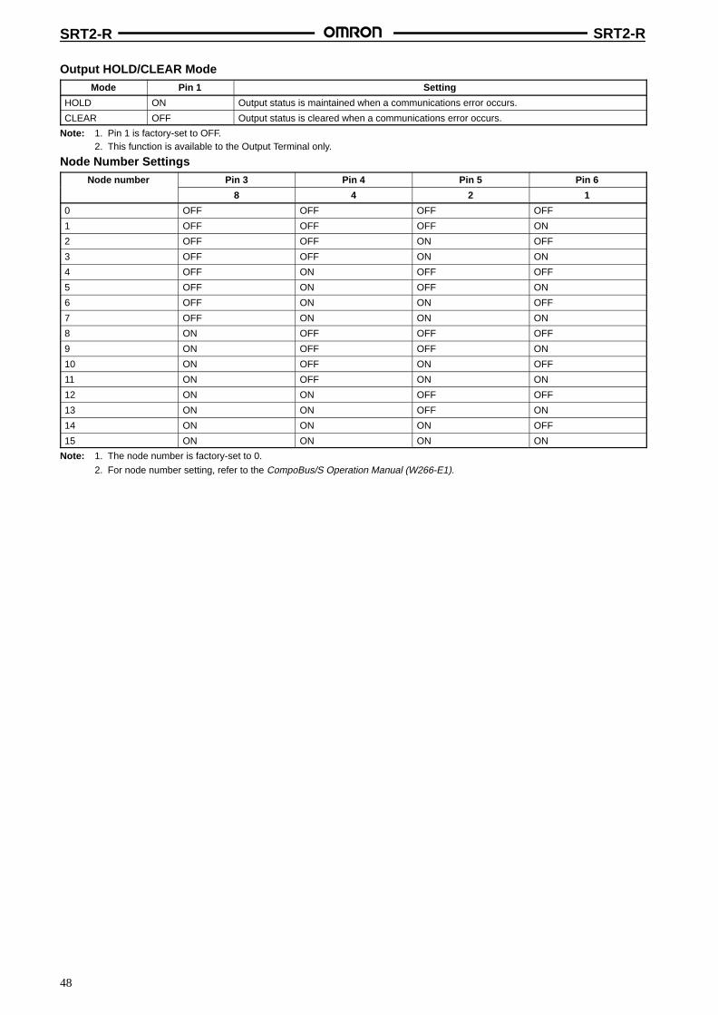
SRT2-R SRT2-R
48
Output HOLD/CLEAR ModeMode Pin 1 Setting
HOLD ON Output status is maintained when a communications error occurs.
CLEAR OFF Output status is cleared when a communications error occurs.
Note: 1. Pin 1 is factory-set to OFF.2. This function is available to the Output Terminal only.
Node Number SettingsNode number Pin 3 Pin 4 Pin 5 Pin 6
8 4 2 1
0 OFF OFF OFF OFF
1 OFF OFF OFF ON
2 OFF OFF ON OFF
3 OFF OFF ON ON
4 OFF ON OFF OFF
5 OFF ON OFF ON
6 OFF ON ON OFF
7 OFF ON ON ON
8 ON OFF OFF OFF
9 ON OFF OFF ON
10 ON OFF ON OFF
11 ON OFF ON ON
12 ON ON OFF OFF
13 ON ON OFF ON
14 ON ON ON OFF
15 ON ON ON ON
Note: 1. The node number is factory-set to 0.
2. For node number setting, refer to the CompoBus/S Operation Manual (W266-E1).

SRT2-R SRT2-R
49
DimensionsNote: All units are in millimeters unless otherwise indicated.
SRT2-ROC08SRT2-ROF08
Mounting Holes
SRT2-ROC16SRT2-ROF16
Mounting Holes
100
50
Two, 4.2 dia. or M4
Two, 4.2 dia. or M4
5050
155
Thirty-two, M3
Sixteen, M3
50 50
50
80
40
135
40
21.511.5
21.511.5

SRT2-R SRT2-R
50
Installation Internal Circuit Configuration
SRT2-ROC08SRT2-ROC16
Note: The G3DZ-2R6PL Power MOS FET Relay is inserted intothis portion of the SRT2-ROF08 and SRT2-ROF16.
Relay drivercircuit
Internalcircuit
Laterblocks
(Seenote)*
Relay drivercircuit
Relay drivercircuit
Relay drivercircuit
External Connections
Lam
p
Lam
p
Lam
p
Lam
p Loadpowersupply
Terminal Arrangement and I/O Device Connection ExampleOutputSRT2-ROC16SRT2-ROF16
Note: 1. Dotted lines indicate internal connections.SRT2-ROC08 and SRT2-ROF08 have the 0 to 7 and COM0 to COM3 terminals only.
2. The above is a connection example of the SRT2-ROC16 with G6D Relays mounted.G3DZ Power MOS FET Relays are mounted to the SRT2-ROF08 and SRT2-ROF16.
24-VDCpower supply
Communicationspath
Load
Pow
ersu
pply
Load
Pow
ersu
pply
Load
Load
Load
Pow
ersu
pply
Load
Pow
ersu
pply
Load
Load
Load
Pow
ersu
pply
Load
Pow
ersu
pply
Load
Load
Load
Pow
ersu
pply
Load
Pow
ersu
pply
Load
Load
*(see note 2)
PrecautionsRefer to the CompoBus/S Operation Manual (W266-E1) before using the Unit.
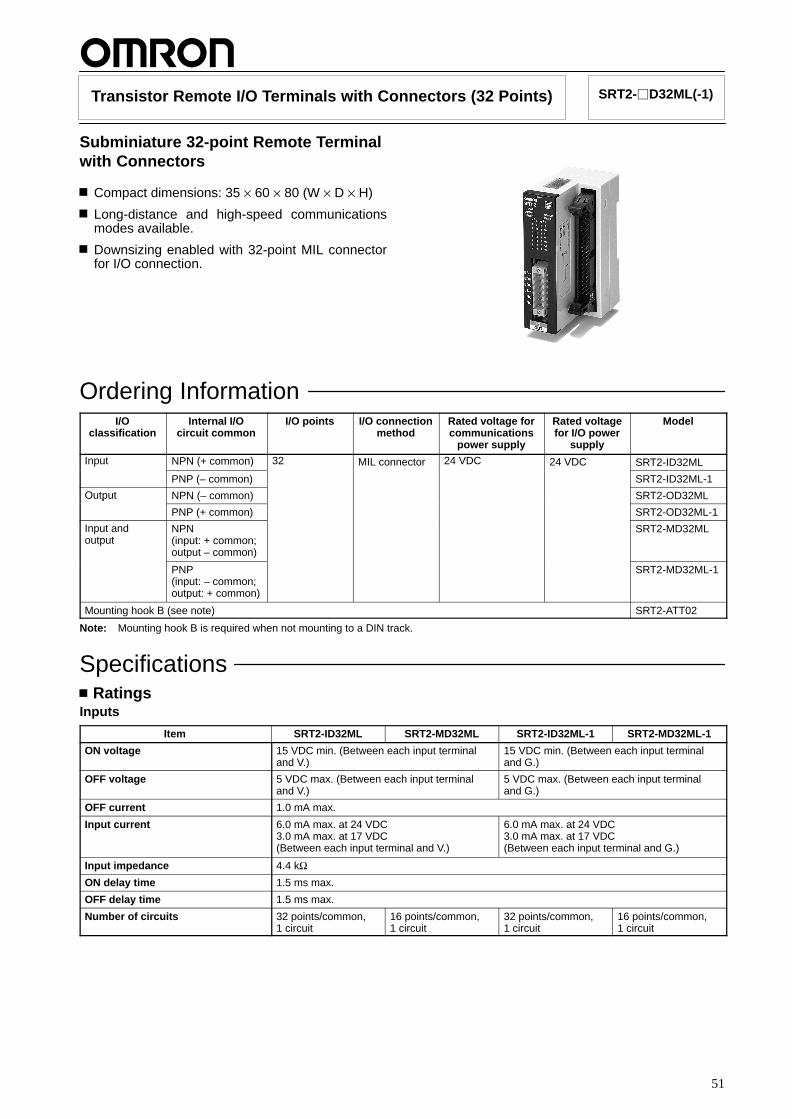
51
Transistor Remote I/O Terminals with Connectors (32 Points) SRT2-D32ML(-1)
Subminiature 32-point Remote Terminalwith Connectors
Compact dimensions: 35 × 60 × 80 (W × D × H)
Long-distance and high-speed communicationsmodes available.
Downsizing enabled with 32-point MIL connectorfor I/O connection.
Ordering InformationI/O
classificationInternal I/O
circuit commonI/O points I/O connection
methodRated voltage forcommunications
power supply
Rated voltagefor I/O power
supply
Model
Input NPN (+ common) 32 MIL connector 24 VDC 24 VDC SRT2-ID32MLp
PNP (– common) SRT2-ID32ML-1
Output NPN (– common) SRT2-OD32MLp
PNP (+ common) SRT2-OD32ML-1
Input andoutput
NPN(input: + common;output – common)
SRT2-MD32ML
PNP(input: – common;output: + common)
SRT2-MD32ML-1
Mounting hook B (see note) SRT2-ATT02
Note: Mounting hook B is required when not mounting to a DIN track.
SpecificationsRatings
Inputs
Item SRT2-ID32ML SRT2-MD32ML SRT2-ID32ML-1 SRT2-MD32ML-1
ON voltage 15 VDC min. (Between each input terminaland V.)
15 VDC min. (Between each input terminaland G.)
OFF voltage 5 VDC max. (Between each input terminaland V.)
5 VDC max. (Between each input terminaland G.)
OFF current 1.0 mA max.
Input current 6.0 mA max. at 24 VDC3.0 mA max. at 17 VDC(Between each input terminal and V.)
6.0 mA max. at 24 VDC3.0 mA max. at 17 VDC(Between each input terminal and G.)
Input impedance 4.4 kΩON delay time 1.5 ms max.
OFF delay time 1.5 ms max.
Number of circuits 32 points/common,1 circuit
16 points/common,1 circuit
32 points/common,1 circuit
16 points/common,1 circuit

SRT2-D32ML(-1) SRT2-D32ML(-1)
52
Outputs
Item SRT2-OD32ML SRT2-MD32ML SRT2-OD32ML-1 SRT2-MD32ML-1
Output current 0.3 A/point4-A common(See notes 1 and 3.)
0.3 A/point 2-A common(See notes 2 and 3.)
0.3 A/point4-A common(See notes 1 and 3.)
0.3 A/point 2-A common(See notes 2 and 3.)
Residual voltage 1.2 V max. (Between the 0.3-A DC outputterminal and G.)
1.2 V max. (Between the 0.3-A DC outputterminal and V.)
Leakage current 0.1 mA max. (Between the 24-VDC outputterminal and G.)
0.1 mA max. (Between the 24-VDC outputterminal and V.)
ON delay time 0.5 ms max.
OFF delay time 1.5 ms max.
Insulation method Photocoupler Photocoupler
Number of circuits 32 points/common,1 circuit
16 points/common,1 circuit
32 points/common,1 circuit
16 points/common,1 circuit
Note: 1. Ensure that the total external load current does not exceed 4 A.
2. Ensure that the total external load current does not exceed 2 A.
3. Ensure that the current per terminal for the V/G terminals does not exceed 1 A.
CharacteristicsCommunications power supplyvoltage
14 to 26.4 VDC
I/O power supply voltage 20.4 to 26.4 VDC
Current consumption forcommunications power supply(also used for internal circuits; seenote)
ID32ML/ID32ML-1: 50 mAMD32ML/MD32ML-1: 60 mAOD32ML/OD32ML-1: 70 mA
Dielectric strength 500 VAC for 1 min (Detection current: 1 mA between insulated circuits.)
Vibration resistance 10 to 150 Hz, 0.7-mm double amplitude or 50 m/s2
Shock resistance 150 m/s2
Ambient temperature Operating: –10°C to 55°C (with no icing or condensation)Storage: –25°C to 65°C
Ambient humidity Operating: 25% to 85% (with no condensation)
Weight ID32ML/ID32ML-1/MD32ML/MD32ML-1: Approx. 100 g max.OD32ML/OD32ML-1: Approx. 90 g
Note: The above current consumption is the value with all points turned ON excluding the current consumption of the external sensor con-nected to the input Remote Terminal and the current consumption of the load connected to the output Remote Terminal.
Applicable ConnectorsType Model Remarks
Flat cable, pressure-welded XG4M-4030-T ---
Strandedi
Socket XG5M-4032-N For AWG 24wire,pressure-welded
XG5M-4035-N For AWG 28to 26
weldedSemi–cover XG5S-2001 ---
Hood cover XG5S-4022 ---

SRT2-D32ML(-1) SRT2-D32ML(-1)
53
NomenclatureNames of Components
Relationship betweenI/O Indicators and Connector
Communicationsconnector
I/O connector
Indicators
Setting switch(for settingcommunicationsmode etc.)
Setting switch(for settingnode address)
DIN trackmountinghook
m ch (IN)
m+1 ch (OUT)
Communicationsconnector
I/O connector

SRT2-D32ML(-1) SRT2-D32ML(-1)
54
IndicatorsDisplay Name Color Status Meaning
PWR Power supply indicator Green Lit Power is being supplied by thecommunications power supply.
Not lit Power is not being supplied by thecommunications power supply.
COMM1COMM2
Communications indicators Yellow Lit I/O is being exchanged normally.COMM2 Not lit A communications error has
occurred, or the Unit is on standby.
ERR1ERR2
Communications error indicators Red Lit A communications error hasoccurred.
Not lit I/O is being exchanged normally, orthe Unit is on standby.
0 to 15 I/O Yellow Lit The corresponding input or output isON.
Not lit The corresponding input or output isOFF, or on standby.
Operation Switch Settings
Rotary switch
Node addresssetting Reserved for
system use
DIP switch
Output HOLD/CLEAR Setting (SRT2-OD/MD32ML(-1))Reserved for system use (SRT2-ID32ML(-1))
Communications mode setting
Node AddressThe node address is set to one of the following hexadecimal values using the rotary switch.
Nodeaddress
Setting(hexadecimal)
Nodeaddress
Setting(hexadecimal)
0 0 8 8
1 1 9 9
2 2 10 A
3 3 11 B
4 4 12 C
5 5 13 D
6 6 14 E
7 7 15 F
Note: 1. Note the following points when using with the C200HW-SRM21-V1/SRM1-CO-V2:
If the maximum number of control points is 128 for inputsand 128 for outputs, node addresses 14 and 15 cannotbe used (SRT2-OD/ID32ML(-1)).If the maximum number of control points is 64 for inputsand 64 for outputs, node addresses in the range 8 to 15cannot be used.
2. Note the following points when using with the CQM1-SRM21-V1:In 8-point Mode:If 2 channels are allocated, node addresses in the range2 to 15 cannot be used.If 4 channels are allocated, node addresses in the range4 to 15 cannot be used.If 8 channels are allocated, node addresses in the range8 to 15 cannot be used.In 4-point Mode:This Unit cannot be used.
Communications Mode SettingThe communications mode is set using SW3 of the DIP switch in the way shown below.
SW3 Communications mode Communicationsdistance
Communicationsspeed
Communications cycletime
OFF High-speedcommunications mode
100 m max. 750 kbps 0.5 ms/0.8 ms
ON Long-distancecommunications mode
500 m max. 93.75 kbps 4.0 ms/6.0 ms
Output HOLD/CLEAR Setting forCommunications Errors (SRT2-OD/MD32ML (-1))The setting of SW4 of the DIP switch determines whether outputdata is held or cleared when a communications error occurs.
SW4 (HOLD) Setting
OFF Output status is cleared.
ON Output status is held.

SRT2-D32ML(-1) SRT2-D32ML(-1)
55
DimensionsNote: All units are in millimeters unless otherwise indicated.
SRT2-ID32ML(-1)SRT2-OD32ML(-1)SRT2-MD32ML(-1)
SRT2-ATT02
Installation Internal Circuit Configuration
SRT2-OD32ML-1
SRT2-ID32ML SRT2-ID32ML-1
SRT2-OD32ML
SRT2-MD32ML SRT2-MD32ML-1
Photocoupler
Photocoupler Photocoupler
Photocoupler
Photo-coupler
Photo-coupler
Photocoupler
Photocoupler
Photocoupler
Photo-coupler
Photocoupler
Photocoupler
Inte
rnal
circ
uit
Inte
rnal
circ
uit
Inte
rnal
circ
uit
Inte
rnal
circ
uit
Inte
rnal
circ
uit
Inte
rnal
circ
uit
Vol
tage
drop
Vol
tage
drop
Vol
tage
drop
Vol
tage
drop
Input
Input
Input
Input
Output
Output
Output
Output
Input
Output
Input
Output
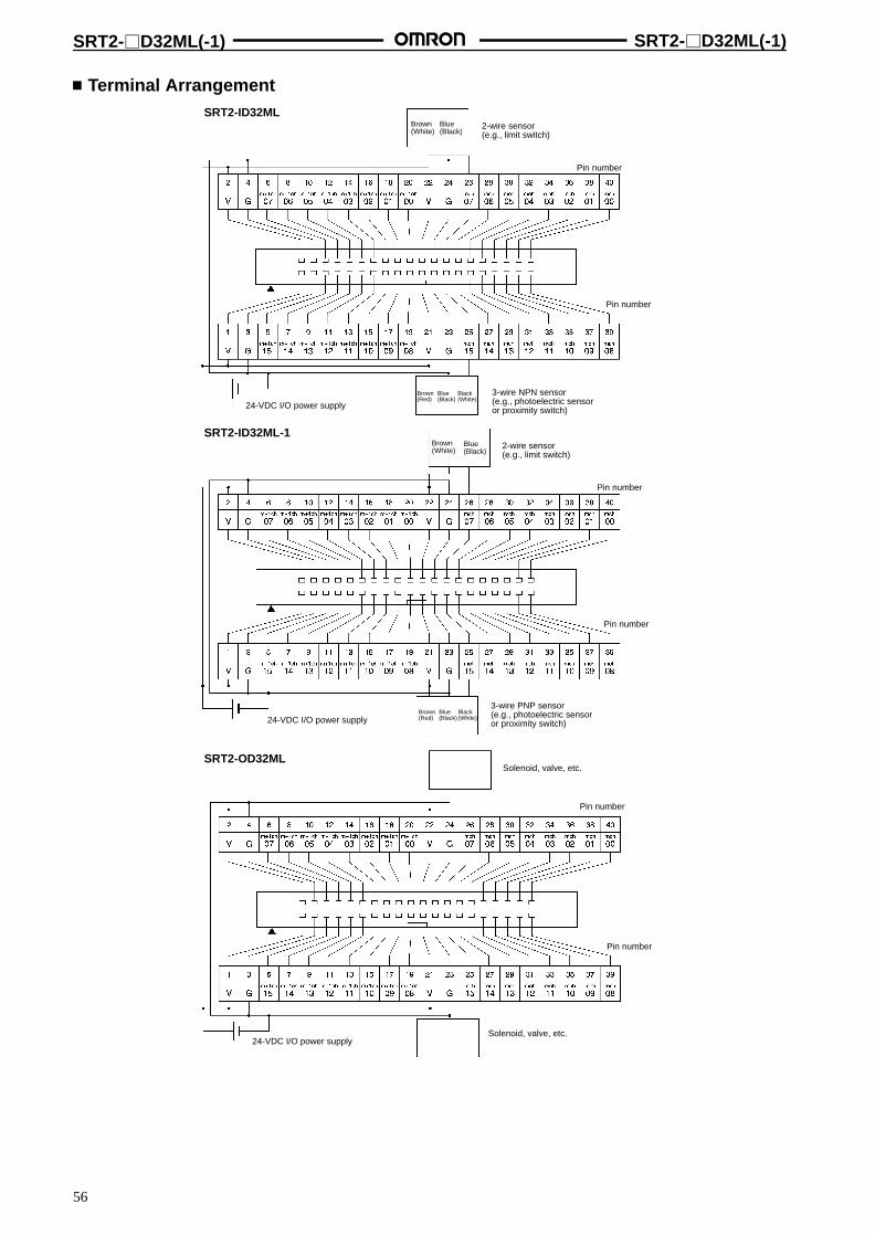
SRT2-D32ML(-1) SRT2-D32ML(-1)
56
Terminal ArrangementSRT2-ID32ML
Brown(White)
Blue(Black)
Pin number
Pin number
2-wire sensor(e.g., limit switch)
Brown(Red)
Blue(Black)
Black(White)
3-wire NPN sensor(e.g., photoelectric sensoror proximity switch)24-VDC I/O power supply
Brown(White)
Blue(Black)
Pin number
Pin number
2-wire sensor(e.g., limit switch)
Brown(Red)
Blue(Black)
Black(White)
3-wire PNP sensor(e.g., photoelectric sensoror proximity switch)24-VDC I/O power supply
SRT2-ID32ML-1
SRT2-OD32MLSolenoid, valve, etc.
Pin number
Pin number
24-VDC I/O power supplySolenoid, valve, etc.
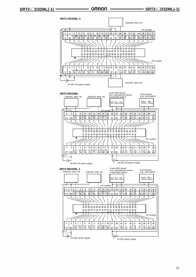
SRT2-D32ML(-1) SRT2-D32ML(-1)
57
SRT2-OD32ML-1Solenoid, valve, etc.
Pin number
Pin number
24-VDC I/O power supplySolenoid, valve, etc.
SRT2-MD32ML
SRT2-MD32ML-1
Brown(White)
Blue(Black)
Solenoid, valve, etc.
Brown(Red)
Blue(Black)
Black(White)
Solenoid, valve, etc.
3-wire NPN sensor(e.g., photoelectric sensoror proximity switch)
2-wire sensor(e.g., limit switch)
Pin number
Pin number
24-VDC I/O power supply24-VDC I/O power supply
Brown(White)
Blue(Black)
Solenoid, valve, etc.
Brown(Red)
Blue(Black)
Black(White)
Solenoid, valve, etc.
3-wire PNP sensor(e.g., photoelectric sensoror proximity switch)
2-wire sensor(e.g., limit switch)
Pin number
Pin number
24-VDC power supply24-VDC power supply

SRT2-D32ML(-1) SRT2-D32ML(-1)
58
PrecautionsFor details on available communications connectors, refer to page 105.
Communications Connector Pin Arrangement
BD H
BD L
24-VDCcommunicationspower supply
Applicable CablesCables with Connectors (2-to-1 Connection)
Model Connected product Applicable Cable Remarks
SRT2-ID32ML G7TC-ID16G7TC-IA16
G79-I50-25-D1 (50 cm)G79-I75-50-D1 (75 cm)
---
SRT2-MD32ML Input side:G7TC-ID16G7TC-IA16
Output side:G7TC-OC16/OC18G70D-SOC16/VSOC16G70A-ZOC16-3
G79-M50-25-D1 (50 cm)G79-M75-50-D1 (75 cm)
Inputs and outputs aredistinguished by color. The tubefor the input side is red and thetube for the output side isyellow.
SRT2-OD32ML G7TC-OC16/OC08G70D-SOC16/VSOC16G70A-ZOC16-3
G79-O50-25-D1 (50 cm)G79-O75-50-D1 (75 cm)
---
SRT2-ID32ML-1 G70A-ZIM16-5 G79-I50-25-D2 (50 cm)G79-I75-50-D2 (75 cm)
---
SRT2-MD32ML-1 Input side:G70A-ZIM16-5
Output side:G70A-ZOC16-4G70D-SOC16-1
G79-M50-25-D2 (50 cm)G79-M75-50-D2 (75 cm)
Inputs and outputs aredistinguished by color. The tubefor the input side is red and thetube for the output side isyellow.
SRT2-OD32ML-1 G70A-ZOC-16-4G70D-SOC16-1
G79-O50-25-D1 (50 cm)G79-O75-50-D1 (75 cm)
---
G7TC-OC16-1 G79-I50-25-D1 (50 cm)G79-I75-50-D1 (75 cm)
---
Cables with Connectors (1-to-1 Connection)
Model Connectedproduct
ApplicableCable
Remarks
Allmodels
XW2B-40GXW2B-40G5XW2D 40G6
XW2Z-C25K(25 cm)
XW2B-40G4XW2B-40G5ode s 0G5
XW2D-40G6 XW2Z-C50K(50 cm)
0G5
Cables with Stranded Wires
Model Connectedproduct
ApplicableCable
Remarks
Allmodels
--- G79-A200C-D1(2 m)
---ode s
G79-A500C-D1(5 m)
Cables with Crimp Terminals
Model Connectedproduct
ApplicableCable
Remarks
Allmodels
--- G79-Y100C-D1(1 m)
---ode s
G79-Y200C-D1(2 m)
G79-Y500C-D1(5 m)
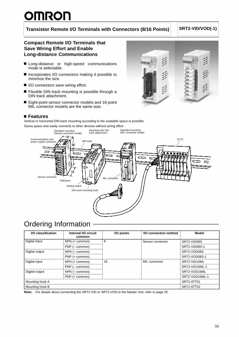
59
Transistor Remote I/O Terminals with Connectors (8/16 Points) SRT2-VID/VOD(-1)
Compact Remote I/O Terminals thatSave Wiring Effort and EnableLong-distance Communications
Long-distance or high-speed communicationsmode is selectable.
Incorporates I/O connectors making it possible tominimize the size.
I/O connectors save wiring effort.
Flexible DIN track mounting is possible through aDIN track attachment.
Eight-point sensor connector models and 16-pointMIL connector models are the same size.
FeaturesVertical or horizontal DIN track mounting according to the available space is possible.
Saves space and easily connects to other devices without wiring effort.Standard mounting(Sensor connector model)
Mounting with DINtrack attachment
Standard mounting(MIL connector model)
Communications andpower supply connector DIN track
G7TC
Sensor connector
Indicators
Setting switch
DIN track mounting hook
MIL connector
Ordering InformationI/O classification Internal I/O circuit
commonI/O points I/O connection method Model
Digital input NPN (+ common) 8 Sensor connector SRT2-VID08Sg p
PNP (– common) SRT2-VID08S-1
Digital output NPN (– common) SRT2-VOD08Sg p
PNP (+ common) SRT2-VOD08S-1
Digital input NPN (+ common) 16 MIL connector SRT2-VID16MLg p
PNP (– common) SRT2-VID16ML-1
Digital output NPN (– common) SRT2-VOD16MLg p
PNP (+ common) SRT2-VOD16ML-1
Mounting hook A SRT2-ATT01
Mounting hook B SRT2-ATT02
Note: For details about connecting the SRT2-VID or SRT2-VOD to the Master Unit, refer to page 25.

SRT2-VID/VOD(-1) SRT2-VID/VOD(-1)
60
SpecificationsRatings
Inputs
Item SRT2-VID08SSRT2-VID08S-1
SRT2-VID16MLSRT2-VID16ML-1
Input current 6 mA max./point at 24 V, 3 mA max./point at 17 V
ON delay time 1.5 ms max.
OFF delay time 1.5 ms max.
ON voltage 15 VDC min. (Between each input terminal and V: NPN. Between each input and G: PNP.)
OFF voltage 5 VDC max. (Between each input terminal and V: NPN. Between each input and G: PNP.)
OFF current 1 mA max.
Insulation method Photocoupler
Maximum number of inputs 8 12
Number of circuits 8 points/common, 1 circuit 16 points/common, 1 circuit
Outputs
Item SRT2-VID08SSRT2-VID08S-1
SRT2-VID16MLSRT2-VID16ML-1
Rated output current 0.3 A/point 0.3 A/point (2-A common) (See note.)
Residual voltage 1.2 V max.
ON delay time 0.5 ms max.
OFF delay time 1.5 ms max.
Leakage current 0.1 mA max.
Insulation method Photocoupler
Number of circuits 8 points/common, 1 circuit 16 points/common, 1 circuit
Note: When using V/G terminals in an MIL connector, ensure that the current per terminal for the V/G terminals does not exceed 1 A.
CharacteristicsCommunications power supplyvoltage
14 to 26.4 VDC
I/O power supply voltage 20.4 to 26.4 VDC (24 VDC +10%/–15%)
I/O power supply current Sensor connector: 2.4 A max., MIL connector: 2.0 A max.
Current consumption (see note) 50 mA max. at 24 VDC
Noise immunity Conforms to IEC61000-4-4, 2 kV (power lines)
Vibration resistance 10 to 150 Hz, 1.0-mm double amplitude or 70 m/s2 (50 m/s2 for SRT2-ATT02)
Shock resistance 200 m/s2
Dielectric strength 500 VAC (between insulated circuits)
Ambient temperature Operating: –10°C to 55°C (with no icing or condensation)Storage: –25°C to 65°C
Ambient humidity Operating: 25% to 85% (with no condensation)Storage: 25% to 85%
Mounting strength No damage when 100 N pull load was applied in all directions (40 N load for SRT2-ATT02)
Terminal strength No damage when the following loads were applied:Communications connector: 100 NSensor connector: 40 NMIL connector: 100 N
Screw tightening torque Communications connector: 0.25 N m
Node address setting Settings made at DIP switch (set before supplying power for Slave communications)
Weight Approx. 75 g max.
Note: The above current consumption is the value with all points turned ON excluding the current consumption of the external sensor con-nected to the input Remote Terminal and the current consumption of the load connected to the output Remote Terminal.

SRT2-VID/VOD(-1) SRT2-VID/VOD(-1)
61
NomenclatureSRT2-VID08S/SRT2-VID08S-1SRT2-VOD08S/SRT2-VOD08S-1(Sensor Connector Models)
SRT2-VID16ML/SRT2-VID16ML-1SRT2-VOD16ML/SRT2-VOD16ML-1(MIL Connector Models)
CommunicationsConnectors
I/O Connectors Indicators
DIP Switch
CommunicationsConnectors
I/O Connectors
Output HOLD/CLEAR Mode Setting
Communications Mode Setting
Node Address SettingReserved for System Use (Always OFF)
Indicators
Indicator DisplayColor Meaning
PWR LitGreen The communications powersupply is ON.
Not lit The communications powersupply is OFF.
COMM LitYellow Normal communications
Not lit A communications error hasoccurred or the Unit is instandby status.
ERR LitRed A communications errorhas occurred.
Not lit Normal communications orthe Unit is in standby status.
0 to 7 (for8-pointI/O)0 to 15 (for16-pointI/O)
LitYellow The corresponding I/Osignal is ON.
Not lit The corresponding I/Osignal is OFF.
Name
Power
Commu-nications
Commu-nicationserror
Input(output)
Output HOLD/CLEAR Mode
SW8 (HOLD) Setting
Output status is cleared.OFF
Output status is maintained.ON
Communications Mode
SW7 (DR) Setting
High-speed communications modeOFF
Long-distance communications modeON
Node Number Settings
Node number Pin 4 Pin 3 Pin 2 Pin 1
8 4 2 1
0 OFF OFF OFF OFF
1 OFF OFF OFF ON
2 OFF OFF ON OFF
3 OFF OFF ON ON
4 OFF ON OFF OFF
5 OFF ON OFF ON
6 OFF ON ON OFF
7 OFF ON ON ON
8 ON OFF OFF OFF
9 ON OFF OFF ON
10 ON OFF ON OFF
11 ON OFF ON ON
12 ON ON OFF OFF
13 ON ON OFF OFF
14 ON ON ON OFF
15 ON ON ON ON
Note: Be sure to perform settings with the Slavepower supply OFF.

SRT2-VID/VOD(-1) SRT2-VID/VOD(-1)
62
DimensionsNote: All units are in millimeters unless otherwise indicated.
SRT2-VID08SSRT2-VID08S-1SRT2-VOD08SSRT2-VOD08S-1
SRT2-VID16MLSRT2-VID16ML-1SRT2-VOD16MLSRT2-VOD16ML-1
SRT2-ATT01
SRT2-ATT02
Dimensions when Unit is mounted.

SRT2-VID/VOD(-1) SRT2-VID/VOD(-1)
63
Installation Internal Circuit Configuration
SRT2-VOD08S-1
SRT2-VID08S SRT2-VID08S-1
SRT2-VOD08S
SRT2-VID16ML SRT2-VID16ML-1
SRT2-VOD16ML SRT2-VOD16ML-1
Photocoupler
Photocoupler Photocoupler
Photocoupler
Photocoupler
Photocoupler
Photocoupler
Photocoupler
Photocoupler
Photocoupler
Photocoupler
Photocoupler
Photocoupler
Photocoupler
Photocoupler
Photocoupler
Inte
rnal
circ
uit
Inte
rnal
circ
uit
Inte
rnal
circ
uit
Inte
rnal
circ
uit
Inte
rnal
circ
uit
Inte
rnal
circ
uit
Inte
rnal
circ
uit
Inte
rnal
circ
uit
Vol
tage
drop
Vol
tage
drop
Vol
tage
drop
Vol
tage
drop

SRT2-VID/VOD(-1) SRT2-VID/VOD(-1)
64
Terminal Arrangement and I/O Device Connection ExamplesSRT2-VID08S SRT2-VID08S-1
SRT2-VID16ML SRT2-VID16ML-1
SRT2-VOD08S
SRT2-VOD16ML
SRT2-VOD08S-1
SRT2-VOD16ML-1
CompoBus/Scommunications CompoBus/S
communicationspower supply
I/O powersupply
Pin numbers
CompoBus/Scommunications CompoBus/S
communicationspower supply
I/O powersupply
Pin numbers
CompoBus/Scommunications
CompoBus/Scommunicationspower supply
I/O powersupply
Pin numbers
CompoBus/Scommunications CompoBus/S
communicationspower supply
I/O powersupply
Pin numbers
CompoBus/Scommunications CompoBus/S
communicationspower supply
I/O powersupply
Pin numbers
CompoBus/Scommunications CompoBus/S
communicationspower supply
I/O powersupply
Pin numbers
CompoBus/Scommunications CompoBus/S
communicationspower supply
I/O powersupply
Pin numbers
CompoBus/Scommunications CompoBus/S
communicationspower supply
I/O powersupply
Pin numbers
Sensor
Brown (Red)
Black (White)Blue (Black)
Three-wire sensor
Sensor
Brown (White)
Blue (Black)
Two-wire sensor
Sensor
Three-wire sensor
Sensor
Two-wire sensor
Sensor
Three-wire sensor
Sensor
Two-wire sensor
Sensor
Three-wire sensor
Sensor
Two-wire sensor
Outputdevice
Solenoid etc.
Outputdevice
Valve etc.
Outputdevice
Solenoid etc.
Outputdevice
Valve etc.
Outputdevice
Solenoid etc.
Outputdevice
Valve etc.
Outputdevice
Solenoid etc.
Outputdevice
Valve etc.
Brown (Red)
Black (White)Blue (Black)
Brown (White)
Blue (Black)
Brown (Red)
Black (White)Blue (Black)
Brown (White)
Blue (Black)
Brown (Red)
Black (White)Blue (Black)
Brown (White)
Blue (Black)
Note: 1. V terminals and G terminals are respectively connected internally.When supplying power for I/O from communications connectors, power can be supplied to the sensor output devices from V and Gterminals.
2. When using an inductive load (solenoid, valve etc.), either use one with an internal reverse electromotive force absorption diode orattach a diode externally.

SRT2-VID/VOD(-1) SRT2-VID/VOD(-1)
65
PrecautionsRefer to the CompoBus/S Operation Manual (W266-E1) beforeusing the Unit.
Communications Connector Pin Arrangement
24-VDCcommunicationspower supply
24-VDC I/Opower supply
CompoBus/S communications
The following solderless terminals are recommended.
• Manufacturer: Weidmuller
Sleeve (Part No. 046290)
Solderlessterminal
Cable
Two-wire insertion (Part No. 901851)
Solderlessterminal
Cable
The following product is a dedicated tool.
• Manufacturer: WeidmullerPZ1.5 Crimper (Part No. 900599)
Sensor Connector Pin Arrangement
SRT2-VID08S/VID08S-1 SRT2-VOD08S/VOD08S-1
Model Cable conductor size
XS8A-0441 0.3 to 0.5 mm2
XS8A-0442 0.14 to 0.2 mm2
Note: The XS8A-0441 or XS8A-0442 Connector is not providedwith the SRT2-VID or SRT2-VOD. Place an order for theconnector separately.
Calculate the cable conductor size as follows.
The following information is given on each sensor cable:
Cable dia. (Number of conductors/Conductor dia.)
Conductor size (mm2) = (Conductor dia./2)2 x π x Number of conductors
Example: E3S-A4 dia. (18/0.12)Conductor size (mm2) = (0.12/2)2 x 3.14 x 18 0.20
The conductor size is 0.2 mm2. Therefore, use the XS8A-0442.
MIL Connector Pin Arrangement
SRT2-VID16ML/VID16ML-1
Function Pin No.
Pin No.
OUT0
IN0
OUT1
IN1
OUT2
IN2
OUT3
IN3
OUT4
IN4
OUT5
IN5
OUT6
IN6
OUT7
IN7
G
G
V
V
20
20
18
18
16
16
14
14
12
12
10
10
8
8
6
6
4
4
2
2
Function
Function
Pin No.
Pin No.
OUT8
IN8
OUT9
IN9
OUT10
IN10
OUT11
IN11
OUT12
IN12
OUT13
IN13
OUT14
IN14
OUT15
IN15
G
G
V
V
19
19
17
17
15
15
13
13
11
11
9
9
7
7
5
5
3
3
1
1
SRT2-VOD16ML/VOD16ML-1
Function
Note: 1. No cable connector is provided. Order the connectorseparately.
• Applicable ConnectorXG4M-2030-T
• Applicable Connector CablesG79-O50CG79-O25CG79-I50CG79-I25C
2. Refer to the following table for ordering information onthe applicable Cables.
Applicable CablesConnectable product Model Applicable Cable
I/O Block G7TC-OC16G7TC-OC08G7TC-ID16-5G7TC-IA16-5
G79-O50C (L = 500 mm)
G7TC-IA16-5G7VC SeriesG70A SeriesG70D Series
↔ G79-O25C (L = 250 mm)
Connector-Terminal Conversion Unit XW2B Series
Digital Display Unit M7F
I/O Block G7TC-ID16G7TC-IA16 ↔
G79-I50C (L = 500 mm)G7TC-IA16G7TC-OC16-1
↔G79-I25C (L = 250 mm)

66
Waterproof Terminals SRT2-D0CL(-1)
Eight Waterproof Terminal ModelsEmphasizing Cost Efficiency
Reduced LaborConnection using connectors reduces the lead timerequired for installation. No tools are required forconnection to a variety of devices.Reduced WiringSignal line wiring has been reduced so that theTerminal can be mounted closer to sensors andother devices.Relay Box not RequiredEnvironment-resistant, dust-tight, drip-proofconstruction (IP67) enables direct on-sitemounting.Easier MaintenanceSignificant reductions not only in setup time but alsomaintenance time.Reduced Space, Improved OperabilityCompact design (160 x 54 mm (W x H)) (8-pointmodels)Settings and connections can be performed usingthe switch and connectors on the front side of theTerminal.
SRT2-D04CL(-1)
SRT2-D08CL(-1)
System ConfigurationSensor
Actuator
Programmable Controller
SRT2-OD04CL(-1)
SRT2-ID04CL(-1)
SRT2-ID08CL(-1)
SRS2-1Terminatingresistor
T-branchConnector
T-branchConnector
XS2R-D427-5T-branch Connector
CompoBus/S
VCTF cable 0.75 mm2 × 4
P/S
T-branchConnector
XS2R-D427-5T-branch Connector

SRT2-D0CL(-1) SRT2-D0CL(-1)
67
Ordering InformationInput/Output Internal I/O circuit
commonI/O points I/O connections
methodRated voltage forI/O power supply
Model
Inputs NPN (+ common) 4 points Sensor I/Ot
24 VDC SRT2-ID04CLp ( )
8 points connector SRT2-ID08CL
PNP (– common) 4 points SRT2-ID04CL-1( )
8 points SRT2-ID08CL-1
Outputs NPN (– common) 4 points SRT2-OD04CLp ( )
8 points SRT2-OD08CL
PNP (+ common) 4 points SRT2-OD04CL-1( )
8 points SRT2-OD08CL-1
SpecificationsGeneral Specifications
Item SRT2-ID04CLSRT2-ID04CL-1SRT2-OD04CL
SRT2-OD04CL-1
SRT2-ID08CLSRT2-ID08CL-1SRT2-OD08CL
SRT2-OD08CL-1
Communications power supplyvoltage
14 to 26.4 VDC (supplied via communications connectors)
I/O power supply voltage 20.4 to 26.4 VDC (24 VDC –15%/+10%)
Communications currentconsumption
15 mA max. 20 mA max.
Ambient temperature Operating: –10°C to 55°C (with no icing)Storage: –25°C to 65°C
Ambient humidity Operating: 25% to 85% (with no condensation)Storage: 25% to 85% (with no condensation)
Connector tightening torque 0.39 to 0.49 N m
Enclosure rating IEC IP67
Mounting method Mounted using M5 screws
Weight Approx. 180 g Approx. 240 g
Communications Media/DistancesCommunications medium 4-conductor cable (VCTF, 0.75 mm2 x 4)
Communicationsdistance
High-speedCommunicationsMode
4-conductor VCTF cable:Main line length: 30 m max.Branch line length: 3 m max.Total branch line length: 30 m max.(When 4-conductor VCTF cable is used to connect fewer than 16 Slaves, the main linecan be up to 100 m long and the total branch line length can be up to 50 m.)
Long-distanceCommunicationsMode
4-conductor VCTF cable:Variable branch wiring (total cable length 200 m max.)(There are no limits on the branching format or main, branch, or total line lengths.The terminator must be connected to the point in the system farthest from the master.)
Note: Use in combination with two-conductor VCTF cables and special flat cables is not possible.
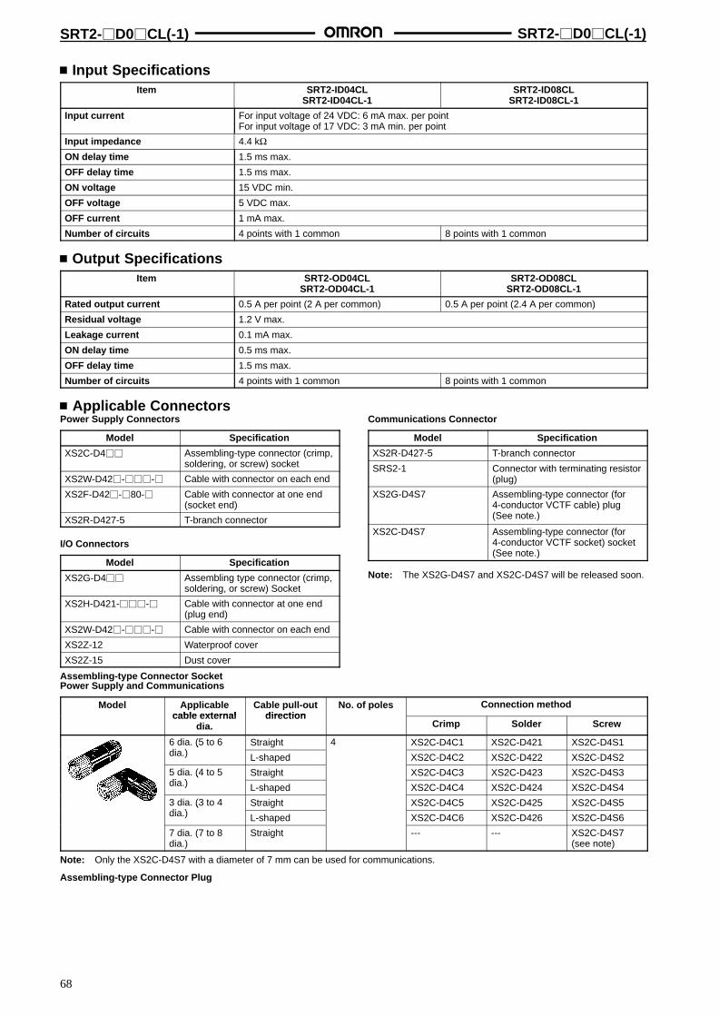
SRT2-D0CL(-1) SRT2-D0CL(-1)
68
Input SpecificationsItem SRT2-ID04CL
SRT2-ID04CL-1SRT2-ID08CL
SRT2-ID08CL-1
Input current For input voltage of 24 VDC: 6 mA max. per pointFor input voltage of 17 VDC: 3 mA min. per point
Input impedance 4.4 kΩON delay time 1.5 ms max.
OFF delay time 1.5 ms max.
ON voltage 15 VDC min.
OFF voltage 5 VDC max.
OFF current 1 mA max.
Number of circuits 4 points with 1 common 8 points with 1 common
Output SpecificationsItem SRT2-OD04CL
SRT2-OD04CL-1SRT2-OD08CL
SRT2-OD08CL-1
Rated output current 0.5 A per point (2 A per common) 0.5 A per point (2.4 A per common)
Residual voltage 1.2 V max.
Leakage current 0.1 mA max.
ON delay time 0.5 ms max.
OFF delay time 1.5 ms max.
Number of circuits 4 points with 1 common 8 points with 1 common
Applicable ConnectorsPower Supply Connectors
Model Specification
XS2C-D4 Assembling-type connector (crimp,soldering, or screw) socket
XS2W-D42-- Cable with connector on each end
XS2F-D42-80- Cable with connector at one end(socket end)
XS2R-D427-5 T-branch connector
I/O Connectors
Model Specification
XS2G-D4 Assembling type connector (crimp,soldering, or screw) Socket
XS2H-D421-- Cable with connector at one end(plug end)
XS2W-D42-- Cable with connector on each end
XS2Z-12 Waterproof cover
XS2Z-15 Dust cover
Communications Connector
Model Specification
XS2R-D427-5 T-branch connector
SRS2-1 Connector with terminating resistor(plug)
XS2G-D4S7 Assembling-type connector (for4-conductor VCTF cable) plug(See note.)
XS2C-D4S7 Assembling-type connector (for4-conductor VCTF socket) socket(See note.)
Note: The XS2G-D4S7 and XS2C-D4S7 will be released soon.
Assembling-type Connector SocketPower Supply and Communications
Model Applicablecable external
Cable pull-outdirection
No. of poles Connection methodcable external
dia.direction
Crimp Solder Screw
6 dia. (5 to 6di )
Straight 4 XS2C-D4C1 XS2C-D421 XS2C-D4S1(dia.) L-shaped XS2C-D4C2 XS2C-D422 XS2C-D4S2
5 dia. (4 to 5di )
Straight XS2C-D4C3 XS2C-D423 XS2C-D4S3(dia.) L-shaped XS2C-D4C4 XS2C-D424 XS2C-D4S4
3 dia. (3 to 4di )
Straight XS2C-D4C5 XS2C-D425 XS2C-D4S5(dia.) L-shaped XS2C-D4C6 XS2C-D426 XS2C-D4S6
7 dia. (7 to 8dia.)
Straight --- --- XS2C-D4S7(see note)
Note: Only the XS2C-D4S7 with a diameter of 7 mm can be used for communications.
Assembling-type Connector Plug
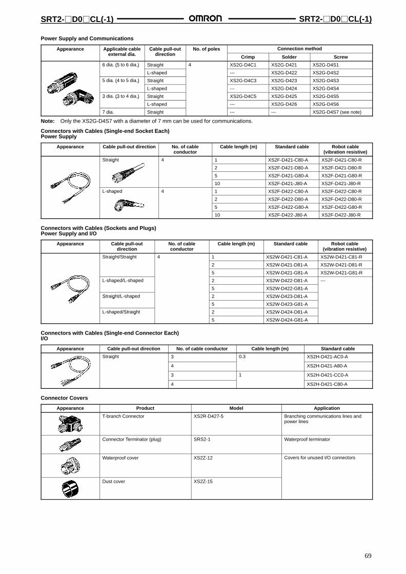
SRT2-D0CL(-1) SRT2-D0CL(-1)
69
Power Supply and Communications
Appearance Applicable cablet l di
Cable pull-outdi ti
No. of poles Connection methodpp ppexternal dia.
C pdirection
p
Crimp Solder Screw
6 dia. (5 to 6 dia.) Straight 4 XS2G-D4C1 XS2G-D421 XS2G-D4S16 (5 6 )
L-shaped --- XS2G-D422 XS2G-D4S2
5 dia. (4 to 5 dia.) Straight XS2G-D4C3 XS2G-D423 XS2G-D4S35 ( 5 )
L-shaped --- XS2G-D424 XS2G-D4S4
3 dia. (3 to 4 dia.) Straight XS2G-D4C5 XS2G-D425 XS2G-D4S53 (3 )
L-shaped --- XS2G-D426 XS2G-D4S6
7 dia. Straight --- --- XS2G-D4S7 (see note)
Note: Only the XS2G-D4S7 with a diameter of 7 mm can be used for communications.
Connectors with Cables (Single-end Socket Each)Power Supply
Appearance Cable pull-out direction No. of cableconductor
Cable length (m) Standard cable Robot cable(vibration resistive)
Straight 4 1 XS2F-D421-C80-A XS2F-D421-C80-RS g
2 XS2F-D421-D80-A XS2F-D421-D80-R
5 XS2F-D421-G80-A XS2F-D421-G80-R
10 XS2F-D421-J80-A XS2F-D421-J80-R
L-shaped 4 1 XS2F-D422-C80-A XS2F-D422-C80-Rp
2 XS2F-D422-D80-A XS2F-D422-D80-R
5 XS2F-D422-G80-A XS2F-D422-G80-R
10 XS2F-D422-J80-A XS2F-D422-J80-R
Connectors with Cables (Sockets and Plugs)Power Supply and I/O
Appearance Cable pull-outdirection
No. of cableconductor
Cable length (m) Standard cable Robot cable(vibration resistive)
Straight/Straight 4 1 XS2W-D421-C81-A XS2W-D421-C81-RS g /S g
2 XS2W-D421-D81-A XS2W-D421-D81-R
5 XS2W-D421-G81-A XS2W-D421-G81-R
L-shaped/L-shaped 2 XS2W-D422-D81-A ---p / p
5 XS2W-D422-G81-A
Straight/L-shaped 2 XS2W-D423-D81-AS g / p
5 XS2W-D423-G81-A
L-shaped/Straight 2 XS2W-D424-D81-Ap /S g
5 XS2W-D424-G81-A
Connectors with Cables (Single-end Connector Each)I/O
Appearance Cable pull-out direction No. of cable conductor Cable length (m) Standard cable
Straight 3 0.3 XS2H-D421-AC0-A
4 XS2H-D421-A80-A
3 1 XS2H-D421-CC0-A
4 XS2H-D421-C80-A
Connector Covers
Appearance Product Model Application
T-branch Connector XS2R-D427-5 Branching communications lines andpower lines
Connector Terminator (plug) SRS2-1 Waterproof terminator
Waterproof cover XS2Z-12 Covers for unused I/O connectors
Dust cover XS2Z-15

SRT2-D0CL(-1) SRT2-D0CL(-1)
70
DimensionsNote: All units are in millimeters unless otherwise indicated.
Models with 4 pointsSRT2-ID04CL/SRT2-ID04CL-1SRT2-OD04CL/SRT2-OD04CL-1
Models with 8 pointsSRT2-ID08CL/SRT2-ID08CL-1SRT2-OD08CL/SRT2-OD08CL-1
Setting SwitchNode number settingsBaud rate settingsHOLD/CLEAR settings
Communications connectorPower supply connector
I/O display
I/O connector
I/O connector
Mounting Dimensions
Three, M5 or 5.3-dia. holes
Setting SwitchNode number settingsBaud rate settingsHOLD/CLEAR settings
Power supply connectorCommunications connector
I/O display
I/O connector
I/O connector
Mounting Dimensions
Three, M5 or 5.3-dia. holes
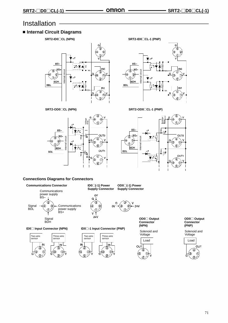
SRT2-D0CL(-1) SRT2-D0CL(-1)
71
Installation Internal Circuit Diagrams
SRT2-OD0CL-1 (PNP)
SRT2-ID0CL (NPN) SRT2-ID0CL-1 (PNP)
SRT2-OD0CL (NPN)
Inte
rnal
circ
uit
Inte
rnal
circ
uit
Inte
rnal
circ
uit
Inte
rnal
circ
uit
Vol
tage
drop Vol
tage
drop
Connections Diagrams for Connectors
Communications Connector ID0(-1) PowerSupply Connector
OD0(-1) PowerSupply Connector
ID0 Input Connector (NPN) ID0-1 Input Connector (PNP)
OD0 OutputConnector(NPN)
OD0 OutputConnector(PNP)
Communicationspower supplyBS–
SignalBDL
Communicationspower supplyBS+
SignalBDH
Two-wiresensor
Three-wiresensor
Solenoid andVoltage
Solenoid andVoltage
Load Load
Two-wiresensor
Three-wiresensor

72
Sensor Terminals SRT2-D08S
Connector Connection Models thatAllows Easy Connection to Sensors andOutput Devices
Sensors with easy-to-wire connectors are easilyattached or detached.
Connects to 2-wire sensors.
Remote teaching of the Sensor Terminal is possiblewith the PLC by using output signals of the SensorTerminal.
DIN track mounting and screw mounting areavailable.
Ordering InformationClassification Internal I/O circuit common I/O points Model
For input NPN (– common) 8 input points SRT2-ID08S
For I/O NPN (– common) 4 input/4 output points SRT2-ND08S
For output NPN (– common) 8 output points SRT2-OD08S
SpecificationsRatings
Input
Item SRT2-ID08S/-ND08S
Input current 10 mA max./point
ON delay time 1 ms max.
OFF delay time 1.5 ms max.
ON voltage 12 VDC min. between each input terminal and VCC, the external sensor power supply
OFF voltage 4 VDC max. between each input terminal and VCC, the external sensor power supply
OFF current 1 mA max.
Insulation method Photocoupler
Input indicator LED (yellow)
Output
Item SRT2-ND08S SRT2-OD08S
Rated output current 20 mA/point 300 mA/point
Residual voltage 1 V max. 0.6 V max.
ON delay time 1 ms max. ---
OFF delay time 1.5 ms max. ---
Leakage current 0.1 mA max.
Insulation method Photocoupler
Output indicator LED (yellow)
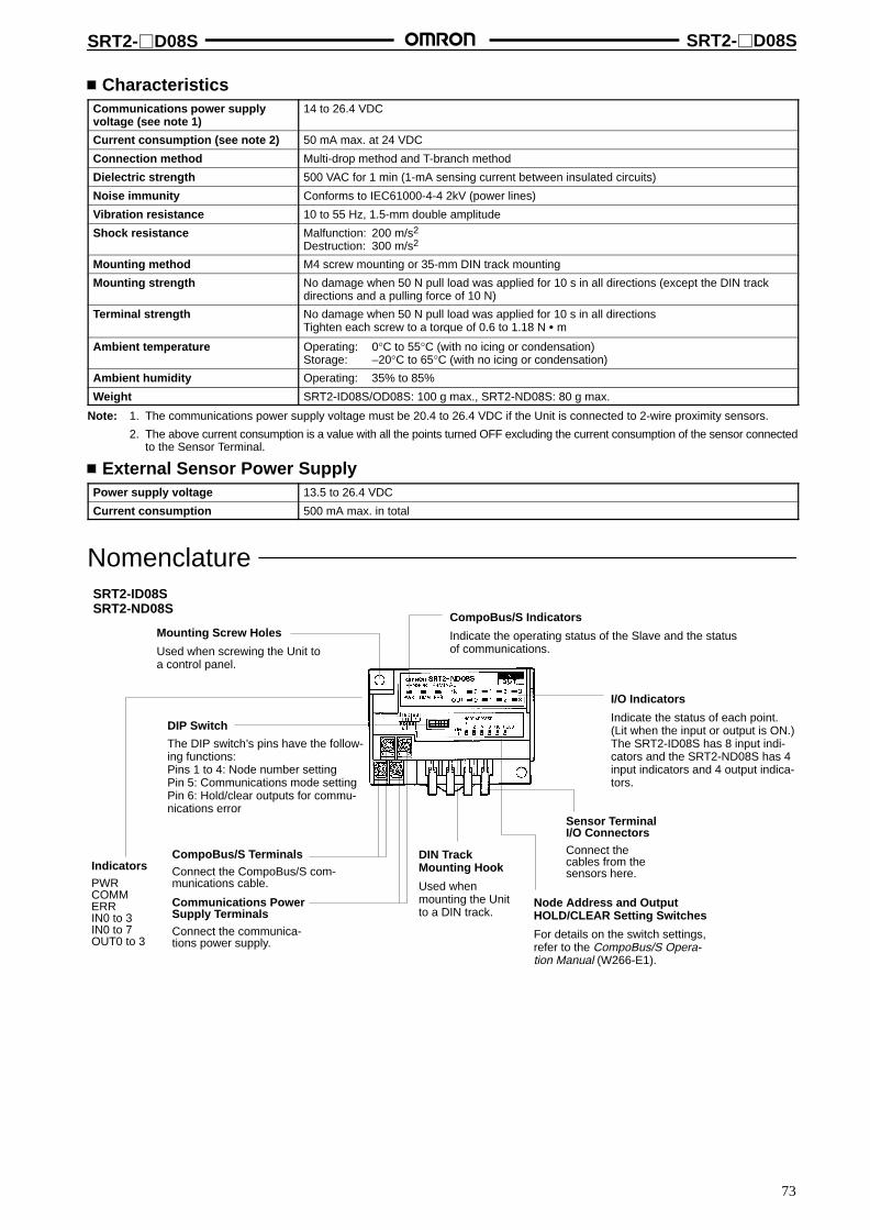
SRT2-D08S SRT2-D08S
73
CharacteristicsCommunications power supplyvoltage (see note 1)
14 to 26.4 VDC
Current consumption (see note 2) 50 mA max. at 24 VDC
Connection method Multi-drop method and T-branch method
Dielectric strength 500 VAC for 1 min (1-mA sensing current between insulated circuits)
Noise immunity Conforms to IEC61000-4-4 2kV (power lines)
Vibration resistance 10 to 55 Hz, 1.5-mm double amplitude
Shock resistance Malfunction: 200 m/s2
Destruction: 300 m/s2
Mounting method M4 screw mounting or 35-mm DIN track mounting
Mounting strength No damage when 50 N pull load was applied for 10 s in all directions (except the DIN trackdirections and a pulling force of 10 N)
Terminal strength No damage when 50 N pull load was applied for 10 s in all directionsTighten each screw to a torque of 0.6 to 1.18 N m
Ambient temperature Operating: 0°C to 55°C (with no icing or condensation)Storage: –20°C to 65°C (with no icing or condensation)
Ambient humidity Operating: 35% to 85%
Weight SRT2-ID08S/OD08S: 100 g max., SRT2-ND08S: 80 g max.
Note: 1. The communications power supply voltage must be 20.4 to 26.4 VDC if the Unit is connected to 2-wire proximity sensors.
2. The above current consumption is a value with all the points turned OFF excluding the current consumption of the sensor connectedto the Sensor Terminal.
External Sensor Power SupplyPower supply voltage 13.5 to 26.4 VDC
Current consumption 500 mA max. in total
NomenclatureSRT2-ID08SSRT2-ND08S
CompoBus/S TerminalsConnect the CompoBus/S com-munications cable.
Sensor TerminalI/O ConnectorsConnect thecables from thesensors here.
I/O Indicators
Indicate the status of each point.(Lit when the input or output is ON.)The SRT2-ID08S has 8 input indi-cators and the SRT2-ND08S has 4input indicators and 4 output indica-tors.
DIP Switch
The DIP switch’s pins have the follow-ing functions:Pins 1 to 4: Node number settingPin 5: Communications mode settingPin 6: Hold/clear outputs for commu-nications error
DIN TrackMounting Hook
Used whenmounting the Unitto a DIN track.
CompoBus/S Indicators
Indicate the operating status of the Slave and the statusof communications.
Mounting Screw Holes
Used when screwing the Unit toa control panel.
IndicatorsPWRCOMMERRIN0 to 3IN0 to 7OUT0 to 3
Communications PowerSupply TerminalsConnect the communica-tions power supply.
Node Address and OutputHOLD/CLEAR Setting Switches
For details on the switch settings,refer to the CompoBus/S Opera-tion Manual (W266-E1).

SRT2-D08S SRT2-D08S
74
IndicatorsIndicator Name Display Color Meaning
PWR Power supply Lit Green The communications power supply is ON.
Not lit The communications power supply is OFF.
COMM Communication Lit Yellow Normal communications
Not lit A communications error has occurred or the Unit is in standby status.
ERR Communication Lit Red A communications error has occurred.error Not lit Normal communications or the Unit is in standby status.
0 to 3 (4 inputs/outputs)
Input Lit Yellow The corresponding input is ON.(4 inputs/outputs)0 to 7 (8 inputs) Not lit The corresponding input is OFF or the Unit is in standby status.
0 to 3(4 i t / t t )
Output Lit Yellow The corresponding output is ON.(4 inputs/outputs) Not lit The corresponding output is OFF or the Unit is in standby status.
Switch SettingAll pins are factory-set to OFF.
Hold/Clear outputs whencommunications erroroccurs (SRT2-ND08S only)
Node numbersettings
Communications mode setting
Pin 5 (Communications Mode Setting)Pin 5 Communications mode
OFF High-speed communications mode
ON Long-distance communications mode
Pin 6 (Output HOLD/CLEAR Mode)(SRT2-ND08S Only)
HOLD Function
OFF Output status is cleared when acommunications error occurs.
ON Output status is maintained when acommunications error occurs.
Node Number SettingsNode number 1 2 4 8
0 OFF OFF OFF OFF
1 ON OFF OFF OFF
2 OFF ON OFF OFF
3 ON ON OFF OFF
4 OFF OFF ON OFF
5 ON OFF ON OFF
6 OFF ON ON OFF
7 ON ON ON OFF
8 OFF OFF OFF ON
9 ON OFF OFF ON
10 OFF ON OFF ON
11 ON ON OFF ON
12 OFF OFF ON ON
13 ON OFF ON ON
14 OFF ON ON ON
15 ON ON ON ON
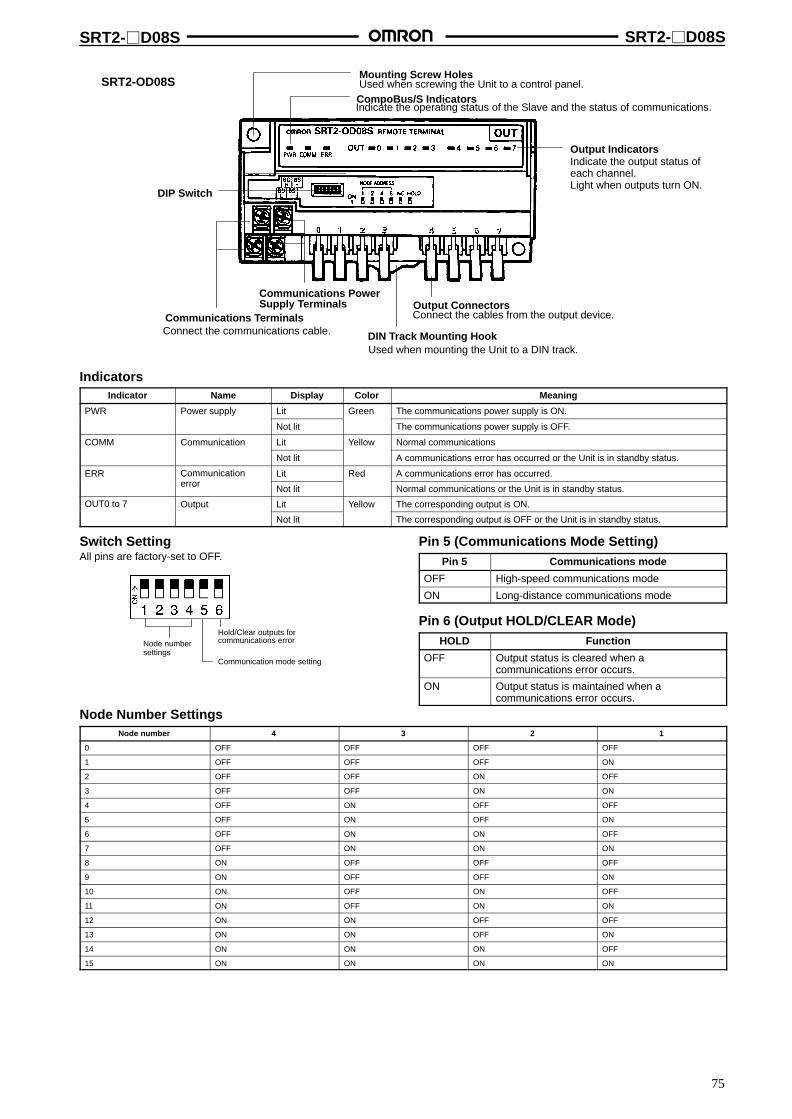
SRT2-D08S SRT2-D08S
75
SRT2-OD08S
DIP Switch
Mounting Screw HolesUsed when screwing the Unit to a control panel.CompoBus/S IndicatorsIndicate the operating status of the Slave and the status of communications.
Output IndicatorsIndicate the output status ofeach channel.Light when outputs turn ON.
Communications Terminals
Communications PowerSupply Terminals
Connect the communications cable. DIN Track Mounting HookUsed when mounting the Unit to a DIN track.
Output ConnectorsConnect the cables from the output device.
IndicatorsIndicator Name Display Color Meaning
PWR Power supply Lit Green The communications power supply is ON.
Not lit The communications power supply is OFF.
COMM Communication Lit Yellow Normal communications
Not lit A communications error has occurred or the Unit is in standby status.
ERR Communication Lit Red A communications error has occurred.Cerror Not lit Normal communications or the Unit is in standby status.
OUT0 to 7 Output Lit Yellow The corresponding output is ON.OU 0
Not lit The corresponding output is OFF or the Unit is in standby status.
Switch SettingAll pins are factory-set to OFF.
Hold/Clear outputs forcommunications errorNode number
settingsCommunication mode setting
Pin 5 (Communications Mode Setting)Pin 5 Communications mode
OFF High-speed communications mode
ON Long-distance communications mode
Pin 6 (Output HOLD/CLEAR Mode)HOLD Function
OFF Output status is cleared when acommunications error occurs.
ON Output status is maintained when acommunications error occurs.
Node Number SettingsNode number 4 3 2 1
0 OFF OFF OFF OFF
1 OFF OFF OFF ON
2 OFF OFF ON OFF
3 OFF OFF ON ON
4 OFF ON OFF OFF
5 OFF ON OFF ON
6 OFF ON ON OFF
7 OFF ON ON ON
8 ON OFF OFF OFF
9 ON OFF OFF ON
10 ON OFF ON OFF
11 ON OFF ON ON
12 ON ON OFF OFF
13 ON ON OFF ON
14 ON ON ON OFF
15 ON ON ON ON

SRT2-D08S SRT2-D08S
76
DimensionsNote: All units are in millimeters unless otherwise indicated.
SRT2-ID08S
Mounting Holes
SRT2-ND08S
Mounting Holes
Cover opening andclosing directions
Two, 4.2 dia or M4
Four, M3
Four, M3
Cover opening andclosing directions
Two, 4.2 dia or M4
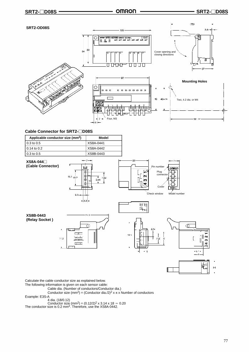
SRT2-D08S SRT2-D08S
77
SRT2-OD08S
Cover opening andclosing directions
Two, 4.2 dia. or M4
Four, M3
Mounting Holes
Cable Connector for SRT2-D08SApplicable conductor size (mm2) Model
0.3 to 0.5 XS8A-0441
0.14 to 0.2 XS8A-0442
0.3 to 0.5 XS8B-0443
XS8B-0443(Relay Socket )
XS8A-044(Cable Connector)
Plug connector
Cover
Model number
Pin number
Check window
Calculate the cable conductor size as explained below.The following information is given on each sensor cable:
Cable dia. (Number of conductors/Conductor dia.)Conductor size (mm2) = (Conductor dia./2)2 x π x Number of conductors
Example: E3S-A4 dia. (18/0.12)Conductor size (mm2) = (0.12/2)2 x 3.14 x 18 0.20
The conductor size is 0.2 mm2. Therefore, use the XS8A-0442.

SRT2-D08S SRT2-D08S
78
Installation Internal Circuit Configuration
SRT2-ID08S SRT2-ND08S
Internalcircuit
Photocoupler
Internalcircuit
Photocoupler
Photo-coupler
SRT2-OD08S
Internalcircuit
For one output
External ConnectionsSRT2-ID08S SRT2-ND08S
Three-wire Sensor Two-wire Sensor Sensor with Teaching Function
Sensor with External Diagnostic function
Sensor with Bank-switching Function
Three-wire Sensor
Bro
wn
Bla
ckB
lue
Sensor
Bro
wn
Blu
e
Sensor
Bro
wn
Bla
ckP
ink
Blu
e
Sensor
Bro
wn
Bla
ck
Blu
e
Sensor
Two-wire Sensor
Bla
ck
Blu
e
Sensor
SRT2-OD08S
Valve, solenoid
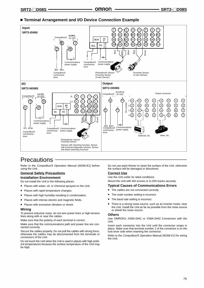
SRT2-D08S SRT2-D08S
79
Terminal Arrangement and I/O Device Connection Example
InputSRT2-ID08S
I/OSRT2-ND08S
Photoelectric SensorProximity Sensor
(Sensor with Teaching Function, Sensorwith External Diagnostic function, Sensorwith Bank-switching Function)
24 VDC
Communicationspower supply
CompoBus/Scommunica-tions
CompoBus/Scommunica-tions
Communicationspower supply
Blu
e
Bro
wn
Blu
e
Bla
ck
Bro
wn
Photoelectric SensorProximity Sensor(3-wire Sensor)
Proximity Sensor(2-wire Sensor)
CompoBus/Scommunica-tions
Communicationspower supply
CompoBus/Scommunica-tions
Communicationspower supply
BLa
ck
Bro
wn
Blu
e
24 VDC
Ora
nge
CompoBus/S
CompoBus/S
OutputSRT2-OD08S
CompoBus/SSOURCE24 VDC
BDL BDH – +CompoBus/Scommunica-tions
Communicationspower supply
Output connector
Pin
num
ber
Solenoid, etc. Valve, etc.
PrecautionsRefer to the CompoBus/S Operation Manual (W266-E1) beforeusing the Unit.
General Safety PrecautionsInstallation EnvironmentDo not install the Unit in the following places.
• Places with water, oil, or chemical sprayed on the Unit.
• Places with rapid temperature changes.
• Places with high humidity resulting in condensation.
• Places with intense electric and magnetic fields.
• Places with excessive vibration or shock.
WiringTo prevent inductive noise, do not wire power lines or high-tensionlines along with or near the cables.
Make sure that the polarity of each terminal is correct.
Make sure that the communications path and power line are con-nected correctly.
Secure the cables properly. Do not pull the cables with strong force,otherwise the cables may be disconnected from the terminals orconnectors of the Unit.
Do not touch the Unit when the Unit is used in places with high ambi-ent temperatures because the surface temperature of the Unit maybe high.
Do not use paint thinner to clean the surface of the Unit, otherwisethe surface will be damaged or discolored.
Correct UseUse the Unit under its rated conditions.
Mount the Unit with M4 screws or to DIN tracks securely.
Typical Causes of Communications Errors• The cables are not connected correctly.
• The node number setting is incorrect.
• The baud rate setting is incorrect.
• There is a strong noise source, such as an inverter motor, nearthe Unit. Install the Unit as far as possible from the noise sourceor shield the noise source.
OthersUse OMRON’s XS8A-0441 or XS8A-0442 Connectors with theUnit.
Insert each connector into the Unit until the connector snaps inplace. Make sure that terminal number 1 of the connector is on thelock lever side when inserting the connector.
Refer to the CompoBus/S Operation Manual (W266-E1) for wiringthe Unit.
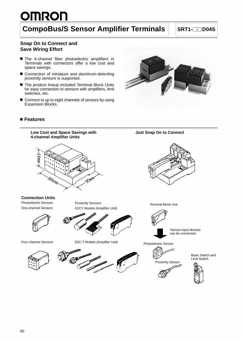
80
CompoBus/S Sensor Amplifier Terminals SRT1-D04S
Snap On to Connect and Save Wiring Effort
The 4-channel fiber photoelectric amplifiers inTerminals with connectors offer a low cost andspace savings.
Connection of miniature and aluminum-detectingproximity sensors is supported.
The product lineup included Terminal Block Unitsfor easy connection to sensors with amplifiers, limitswitches, etc.
Connect to up to eight channels of sensors by usingExpansion Blocks.
Features
Low Cost and Space Savings with4-channel Amplifier Units
Just Snap On to Connect
Connection UnitsPhotoelectric Sensors
One-channel Sensors
Four-channel Sensors
Terminal Block Unit
Photoelectric Sensor
Various input devicescan be connected.
Proximity Sensor
Basic Switch andLimit Switch
Proximity Sensors
E2CY Models (Amplifier Unit)
E2C-T Models (Amplifier Unit)
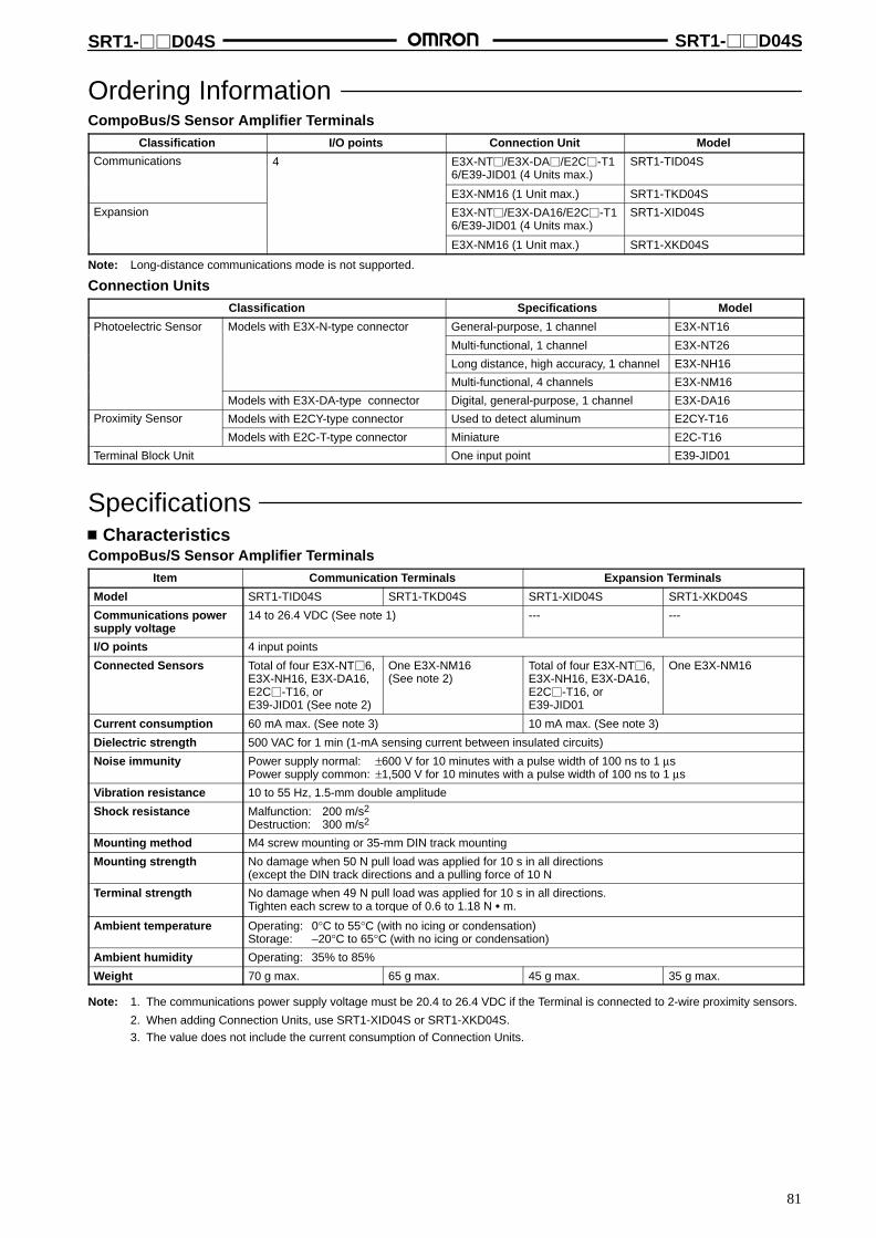
SRT1-D04S SRT1-D04S
81
Ordering InformationCompoBus/S Sensor Amplifier Terminals
Classification I/O points Connection Unit Model
Communications 4 E3X-NT/E3X-DA/E2C-T16/E39-JID01 (4 Units max.)
SRT1-TID04S
E3X-NM16 (1 Unit max.) SRT1-TKD04S
Expansion E3X-NT/E3X-DA16/E2C-T16/E39-JID01 (4 Units max.)
SRT1-XID04S
E3X-NM16 (1 Unit max.) SRT1-XKD04S
Note: Long-distance communications mode is not supported.
Connection UnitsClassification Specifications Model
Photoelectric Sensor Models with E3X-N-type connector General-purpose, 1 channel E3X-NT16
Multi-functional, 1 channel E3X-NT26
Long distance, high accuracy, 1 channel E3X-NH16
Multi-functional, 4 channels E3X-NM16
Models with E3X-DA-type connector Digital, general-purpose, 1 channel E3X-DA16
Proximity Sensor Models with E2CY-type connector Used to detect aluminum E2CY-T16y
Models with E2C-T-type connector Miniature E2C-T16
Terminal Block Unit One input point E39-JID01
SpecificationsCharacteristics
CompoBus/S Sensor Amplifier TerminalsItem Communication Terminals Expansion Terminals
Model SRT1-TID04S SRT1-TKD04S SRT1-XID04S SRT1-XKD04S
Communications powersupply voltage
14 to 26.4 VDC (See note 1) --- ---
I/O points 4 input points
Connected Sensors Total of four E3X-NT6,E3X-NH16, E3X-DA16,E2C-T16, orE39-JID01 (See note 2)
One E3X-NM16 (See note 2)
Total of four E3X-NT6,E3X-NH16, E3X-DA16,E2C-T16, orE39-JID01
One E3X-NM16
Current consumption 60 mA max. (See note 3) 10 mA max. (See note 3)
Dielectric strength 500 VAC for 1 min (1-mA sensing current between insulated circuits)
Noise immunity Power supply normal: ±600 V for 10 minutes with a pulse width of 100 ns to 1 µsPower supply common: ±1,500 V for 10 minutes with a pulse width of 100 ns to 1 µs
Vibration resistance 10 to 55 Hz, 1.5-mm double amplitude
Shock resistance Malfunction: 200 m/s2
Destruction: 300 m/s2
Mounting method M4 screw mounting or 35-mm DIN track mounting
Mounting strength No damage when 50 N pull load was applied for 10 s in all directions(except the DIN track directions and a pulling force of 10 N
Terminal strength No damage when 49 N pull load was applied for 10 s in all directions.Tighten each screw to a torque of 0.6 to 1.18 N m.
Ambient temperature Operating: 0°C to 55°C (with no icing or condensation)Storage: –20°C to 65°C (with no icing or condensation)
Ambient humidity Operating: 35% to 85%
Weight 70 g max. 65 g max. 45 g max. 35 g max.
Note: 1. The communications power supply voltage must be 20.4 to 26.4 VDC if the Terminal is connected to 2-wire proximity sensors.
2. When adding Connection Units, use SRT1-XID04S or SRT1-XKD04S.
3. The value does not include the current consumption of Connection Units.
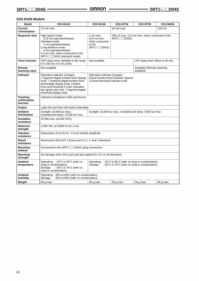
SRT1-D04S SRT1-D04S
82
E3X-DA/N ModelsModel E3X-DA16 E3X-NH16 E3X-NT16 E3X-NT26 E3X-NM16
Currentconsumption
75 mA max. 50 mA max. 150 mA
Response time High-speed mode:0.25 ms (operate/release)
Standard mode:1 ms (operate/release)
Long-distance mode:4 ms (operate/release)
4.0 ms max. when connected to theSRT1-D04S (standard mode)
1 ms max.(4.0 ms max.when connectedto theSRT1-D04S)
500 µS max. (2.0 ms max. when connected to theSRT1-D04S)
Timer function OFF-delay timer (settable in the range0 to 200 ms in 5-ms units)
Not available OFF-delay timer (fixed to 40 ms)
Remoteteaching input
Not available Available (Remote teachingdisabled)
Indicator Operation indicator (orange),7-segment digital incident level display(red), 7-segment digital incident levelpercentage display (red), incidentlevel and threshold 2-color indicationbar (green and red), 7-segment digitalthreshold display (red)
Operation indicator (orange)8-level incident level indicator (green)13-level threshold indicator (red)
Teachingconfirmationfunction
Indicators (red/green LED) and buzzer
Output Light ON and Dark ON switch selectable
Ambientillumination
Sunlight: 20,000 lux max.;incandescent lamp: 10,000 lux max.
Sunlight: 10,000 lux max.; incandescent lamp: 3,000 lux max.
Insulationresistance
20 MΩ max. (at 500 VDC)
Dielectricstrength
1,000 VAC at 50/60 Hz for 1 min
Vibrationresistance
Destruction:10 to 55 Hz, 1.5-mm double amplitude
Shockresistance
Destruction:500 m/s2 3 times each in X, Y, and Z directions
Mountingmethod
Connected to the SRT1-D04S using connectors.
Mountingstrength
No damage when 49 N pull load was applied for 10 s in all directions.
Ambienttemperature
Operating: –25°C to 55°C (with noicing or condensation)Storage: –30°C to 70°C (with noicing or condensation)
Operating: –25°C to 55°C (with no icing or condensation)Storage: –40°C to 70°C (with no icing or condensation)
Ambienthumidity
Operating: 35% to 85% (with no condensation)Storage: 35% to 85% (with no condensation)
Weight 60 g max. 30 g max. 30 g max. 30 g max. 60 g max.

SRT1-D04S SRT1-D04S
83
E2CY Models (Amplifier Unit)Supply voltage 12 to 24 VDC ± 10%, ripple (p-p): 10% max.
Current consumption 40 mA max.
Sensing distance adjustment range 10% min. of stable sensing distance
Adjustment method Teaching
Differential travel 10% max. of sensing distance in FINE mode.15% max. of sensing distance in NORM mode.
Response time Refer to the response frequency of the Sensor Head in use.
Control output NPN open collector output of 100 mA max. with a max. residual voltage of 1 V
Self-diagnostic output NPN open collector output of 100 mA max. with a max. residual voltage of 1 V
Circuit protection Reverse polarity, surge voltage, and load short-circuit (for both control output and diagnosisoutput)
Cord length compensation Freely cut or extended within a range between 0.5 and 5 m
Indicators Operation indicator (orange)Excess gain level indicators (ON in green with sensing object in proximity and ON in orangewith no sensing object in proximity)Fine-tuning indicator (green)
Ambient temperature Operating: –10 to 55°C (with no icing or condensation)
Ambient humidity Operating: 35% to 85% (with no condensation)
Influence of temperature onsensing distance (at 23°C)
±10% max. (–10°C to 55°C)
Insulation resistance 50 MΩ min. (at 500 VDC) between current carry parts and case
Dielectric strength 1,000 VAC (50/60 Hz) for 1 min between current carry parts and case
Vibration resistance Destruction: 10 to 150 Hz, 1.5-mm double amplitude or 100 m/s2 for 2 hours each in X, Y, andZ directions
Shock resistance Destruction: 300 m/s2 for 3 hours each in X, Y, and Z directions
Mounting method Connected to the SRT1-D04S using connectors.
Mounting strength No damage when 49 N pull load was applied for 10 s in all directions.
Degree of protection IEC60529 IP50 with the sensor cord and protective cover attached
Material Case: PTB resinCover: PC
Teaching monitor function Orange and green indicators shared by operation and excess gain indication
Output status Normally open or normally closed selectable
Weight (packaged state) Approx. 30 g
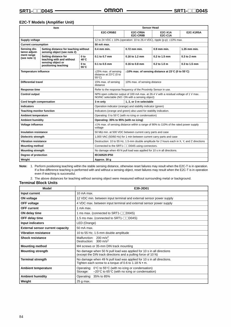
SRT1-D04S SRT1-D04S
84
E2C-T Models (Amplifier Unit)Item Sensor Head
E2C-CR5B2 E2C-CR8AE2C-CR8B
E2C-X1AE2C-C1A
E2C-X1R5A
Supply voltage 12 to 24 VDC ± 10% (operation: 10 to 26.4 VDC), ripple (p-p): ±10% max.
Current consumption 50 mA max.
Sensing dis-tance adjust-
t
Setting distance for teaching withoutsensing object (see note 2)
0.4 mm min. 0.72 mm min. 0.9 mm min. 1.35 mm min.tance adjustment range(see note 1) Setting distance for
teaching with and withouti bj t
0 to40°C
0.1 to 0.7 mm 0.16 to 1.2 mm 0.2 to 1.5 mm 0.3 to 2 mmteaching with and withoutsensing object orpositioning teaching 0 to
55°C0.1 to 0.5 mm 0.16 to 0.8 mm 0.2 to 1.0 m 0.3 to 1.5 mm
Temperature influence ±25% max. of sensingdistance at 23°C (0 to55°C)
±10% max. of sensing distance at 23°C (0 to 55°C)
Differential travel 15% max. of sensingdistance
10% max. of sensing distance
Response time Refer to the response frequency of the Proximity Sensor in use.
Control output NPN open collector output of 100 mA max. at 26.4 V with a residual voltage of 1 V max.NO/NC selectable (NO: ON with a sensing object)
Cord length compensation 3 m only 1, 2, or 3 m selectable
Indicators Operation indicator (orange) and stability indicator (green)
Teaching monitor function Indicators (orange and green) also used for stability indication.
Ambient temperature Operating: 0 to 55°C (with no icing or condensation)
Ambient humidity Operating: 35% to 95% (with no icing)
Voltage influence ±1% max. of sensing distance within a range of 90% to 110% of the rated power supplyvoltage
Insulation resistance 50 MΩ min. at 500 VDC between current carry parts and case
Dielectric strength 1,000 VAC (50/60 Hz) for 1 min between current carry parts and case
Vibration resistance Destruction: 10 to 55 Hz, 1.5-mm double amplitude for 2 hours each in X, Y, and Z directions
Mounting method Connected to the SRT1-D04S using connectors.
Mounting strength No damage when 49 N pull load was applied for 10 s in all directions.
Degree of protection IEC60529 IP50
Weight Approx. 30 g
Note: 1. Perform positioning teaching within the stable sensing distance, otherwise reset failures may result when the E2C-T is in operation.If a fine-difference teaching is performed with and without a sensing object, reset failures may result when the E2C-T is in operationeven if teaching is successful.
2. The above distances for teaching without sensing object were measured without surrounding metal or background.
Terminal Block UnitsModel E39-JID01
Input current 10 mA max.
ON voltage 12 VDC min. between input terminal and external sensor power supply
OFF voltage 4 VDC max. between input terminal and external sensor power supply
OFF current 1 mA max.
ON delay time 1 ms max. (connected to SRT1-D04S)
OFF delay time 1.5 ms max. (connected to SRT1-D04S)
Input indicators LED (Orange)
External sensor current capacity 50 mA max.
Vibration resistance 10 to 55 Hz, 1.5-mm double amplitude
Shock resistance Malfunction: 200 m/s2
Destruction: 300 m/s2
Mounting method M4 screws or 35-mm DIN track mounting
Mounting strength No damage when 50 N pull load was applied for 10 s in all directions(except the DIN track directions and a pulling force of 10 N)
Terminal strength No damage when 49 N pull load was applied for 10 s in all directions.Tighten each screw to a torque of 0.6 to 1.18 N m.
Ambient temperature Operating: 0°C to 55°C (with no icing or condensation)Storage: –20°C to 65°C (with no icing or condensation)
Ambient humidity Operating: 35% to 85%
Weight 25 g max.

SRT1-D04S SRT1-D04S
85
NomenclatureSRT1-TID04SSRT1-TKD04S
Mounting Screw Holes
CommunicationsTerminals
Communications Power SupplyTerminals
Contact 0
Contact 1Contact 2
Contact 3DIN Track Mounting Hook
Node Number Settings
Refer to the CompoBus/S Operation Manual (W266-E1)for details on DIP switch settings.
Mounting Screw Holes
DIN Track Mounting HookContacts 0 to 3
Communications Power SupplyTerminalsConnect a 24-VDC power supply.
CommunicationsTerminalsConnect a com-munications cable.
DIP Switch
IndicatorsIndicator Name Display Color Meaning
PWR Power supply Lit Green The communications power supply is ON.pp y
Not lit The communications power supply is OFF.
COMM Communications Lit Yellow Normal communications.
Not lit A communications error has occurred or the Unit is in standby status.
ERR Communications Lit Red A communications error has occurred.error Not lit Normal communications or the Unit is in standby status.

SRT1-D04S SRT1-D04S
86
DimensionsNote: All units are in millimeters unless otherwise indicated.
SRT1-TID04S
Two, 4.2 dia. or M4
Two, 4.5 dia.Mounting Holes
(75)
3.4
Two, 4.2 dia. or M4
Two, 4.5 dia.SRT1-XID04S
Mounting Holes
(75)
3.4
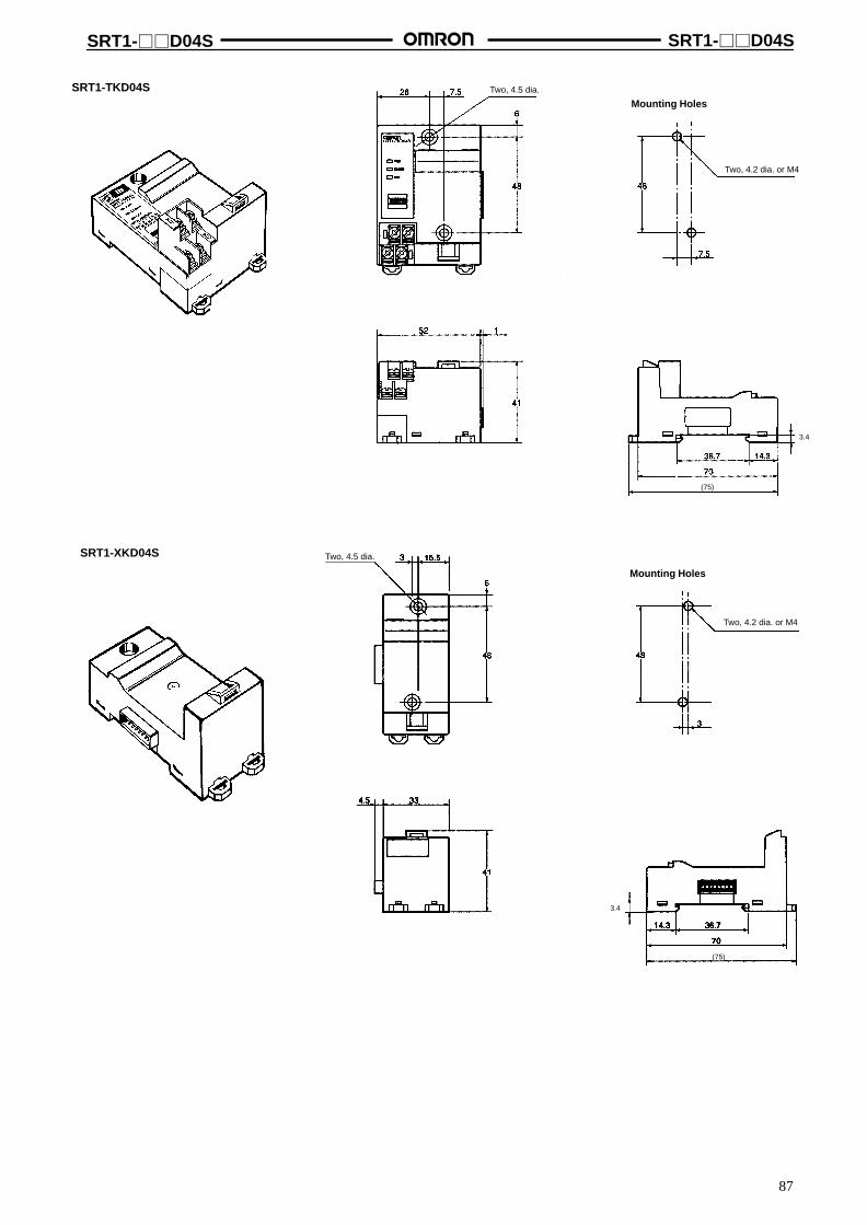
SRT1-D04S SRT1-D04S
87
SRT1-TKD04S
Two, 4.2 dia. or M4
Two, 4.5 dia.
Mounting Holes
(75)
3.4
SRT1-XKD04S
Two, 4.2 dia. or M4
Two, 4.5 dia.
Mounting Holes
(75)
3.4
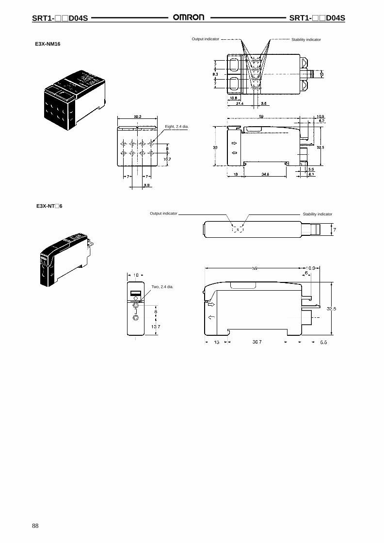
SRT1-D04S SRT1-D04S
88
E3X-NM16Output indicator Stability indicator
Eight, 2.4 dia.
E3X-NT6Output indicator Stability indicator
Two, 2.4 dia.
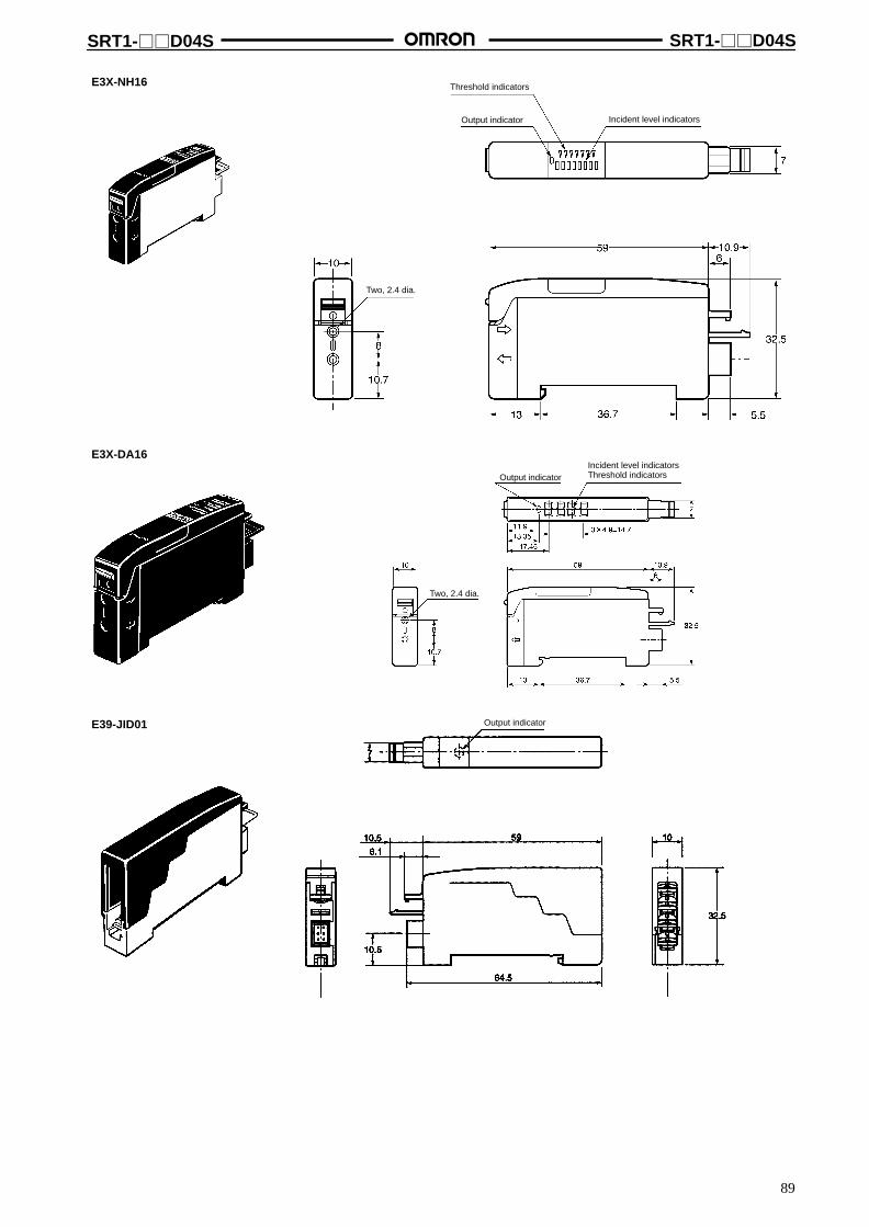
SRT1-D04S SRT1-D04S
89
E3X-NH16
Incident level indicators
Threshold indicators
Output indicator
Two, 2.4 dia.
E3X-DA16
Output indicator
Two, 2.4 dia.
Incident level indicatorsThreshold indicators
E39-JID01 Output indicator

SRT1-D04S SRT1-D04S
90
E2CY-T16Output indicator
Detection level indicatorOperation mode indicator
E2C-T16Output indicator
Stability indicator
Installation Internal Circuit Configuration
E39-JID01
Internalcircuit

SRT1-D04S SRT1-D04S
91
PrecautionsRefer to the CompoBus/S Operation Manual (W266-E1) before using the Terminal.
General-purpose Sensors and the EquivalentCompoBus/S Sensors
CompoBus/Sproduct
General-purposeproduct
Difference
E3X-NT16 E3X-NT11 ExternallE3X-NT26 E3X-NT21 appearance only
E3X-NM16 E3X-NM11
E3X-NH16 E3X-NH11
E3X-DA16 E3X-DA11
E2CY-T16 E2CY-T11
E2C-T16 E2C-T11
General Safety PrecautionsConnection UnitsUse only the Connection Units listed in this data sheet for the Sen-sor Amplifier Units.
E39-JID01 Terminal Block UnitDo not apply any voltage to the Terminal Block Unit.
Correct UseExpanding Sensor Amplifier Terminals
1. Remove the cover from the side of the SRT1-TD04S. (SeeFigure 1.)
2. When the cover is removed, you can see the expansionconnector inside.
3. Connect this expansion connector to the connector locatedon the side of the SRT1-XD04S. (See Figure 2.)
Figure 1
Cover
Figure 2
Connector
Attaching and Removing Connection UnitsSensor Amplifier Terminal Connection Unit
SRT1-TID04S
SRT1-XID04S
E3X-DA16E3X-NT6E39-JID01E3X-NH6E2CY-T16E2C-T16
(SRT1-TID04S, SRT1-XID04S, E3X-NT6, E39-JID01)
Attaching Connection Units1. Hook Section A of the Connection Unit onto Section B of the
Sensor Amplifier Terminal.
2. Push in the Connection Unit until Section C locks insideSection D of the Sensor Amplifier Terminal.
Section C
Section D
Section A
Section B
Bottom View
Section A
Removing Connection Units1. While pushing Section D, pull the Connection Unit in direction
E.
2. When Section D releases from the lock, the Connection Unitcan be removed.
Push here
Section D
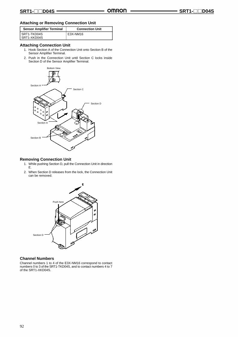
SRT1-D04S SRT1-D04S
92
Attaching or Removing Connection UnitSensor Amplifier Terminal Connection Unit
SRT1-TKD04SSRT1-XKD04S
E3X-NM16
Attaching Connection Unit1. Hook Section A of the Connection Unit onto Section B of the
Sensor Amplifier Terminal.
2. Push in the Connection Unit until Section C locks insideSection D of the Sensor Amplifier Terminal.
Bottom View
Section A
Section C
Section D
Section A
Section B
Removing Connection Unit1. While pushing Section D, pull the Connection Unit in direction
E.
2. When Section D releases from the lock, the Connection Unitcan be removed.
Push here
Section D
Channel NumbersChannel numbers 1 to 4 of the E3X-NM16 correspond to contactnumbers 0 to 3 of the SRT1-TKD04S, and to contact numbers 4 to 7of the SRT1-XKD04S.
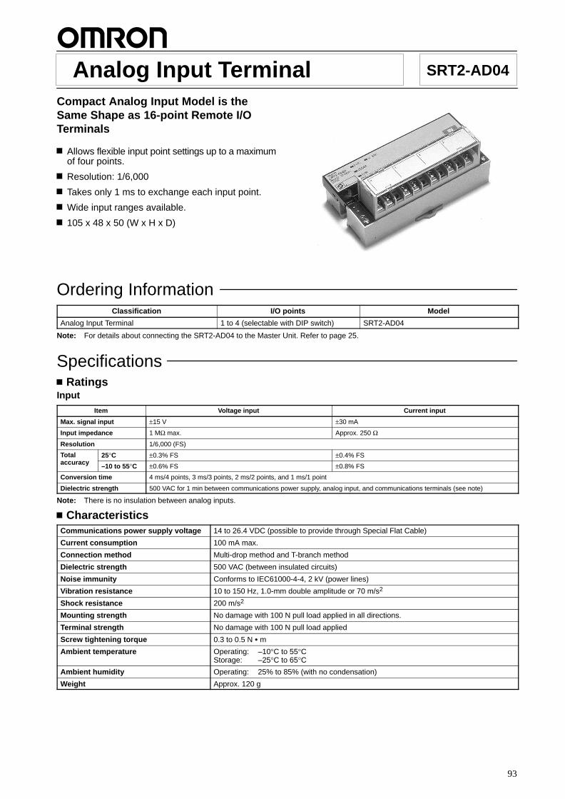
93
Analog Input Terminal SRT2-AD04
Compact Analog Input Model is theSame Shape as 16-point Remote I/OTerminals
Allows flexible input point settings up to a maximumof four points.
Resolution: 1/6,000
Takes only 1 ms to exchange each input point.
Wide input ranges available.
105 x 48 x 50 (W x H x D)
Ordering InformationClassification I/O points Model
Analog Input Terminal 1 to 4 (selectable with DIP switch) SRT2-AD04
Note: For details about connecting the SRT2-AD04 to the Master Unit. Refer to page 25.
SpecificationsRatings
Input
Item Voltage input Current input
Max. signal input ±15 V ±30 mA
Input impedance 1 MΩ max. Approx. 250 Ω
Resolution 1/6,000 (FS)
Total 25°C ±0.3% FS ±0.4% FSaccuracy –10 to 55°C ±0.6% FS ±0.8% FS
Conversion time 4 ms/4 points, 3 ms/3 points, 2 ms/2 points, and 1 ms/1 point
Dielectric strength 500 VAC for 1 min between communications power supply, analog input, and communications terminals (see note)
Note: There is no insulation between analog inputs.
CharacteristicsCommunications power supply voltage 14 to 26.4 VDC (possible to provide through Special Flat Cable)
Current consumption 100 mA max.
Connection method Multi-drop method and T-branch method
Dielectric strength 500 VAC (between insulated circuits)
Noise immunity Conforms to IEC61000-4-4, 2 kV (power lines)
Vibration resistance 10 to 150 Hz, 1.0-mm double amplitude or 70 m/s2
Shock resistance 200 m/s2
Mounting strength No damage with 100 N pull load applied in all directions.
Terminal strength No damage with 100 N pull load applied
Screw tightening torque 0.3 to 0.5 N m
Ambient temperature Operating: –10°C to 55°CStorage: –25°C to 65°C
Ambient humidity Operating: 25% to 85% (with no condensation)
Weight Approx. 120 g

SRT2-AD04 SRT2-AD04
94
NomenclatureSRT2-AD04
Mounting Screw Holes
DIN Track Mounting Hook
Terminal Block
Indicators
IndicatorsIndicator Name Color Display Meaning
PWR Power supply Green Lit The communications power supply is ON.
Not lit The communications power supply is OFF.
COMM Communication Yellow Lit Normal communications
Not lit A communications error has occurred or the Unit is in standby status.
ERR Communication Red Lit A communications error has occurred.error Not lit Normal communications or the Unit is in standby status.
U.ERR Unit error Red Lit An error has occurred in the Unit.
Not lit Normal communications or the Unit is in standby status.
DIP Switch (SW101)(Open cover to access.)
Pin 1 Pin 2 Input points
OFF OFF 4 points (default setting)
OFF ON 3 points (inputs 0 to 2 enabled)
ON OFF 2 points (inputs 0 and 2 enabled)
ON ON 1 point (input 0 enabled)
Pin 3 Communications mode
OFF High-speed communications (default setting)
ON Long-distance communications
Pin 4 Be sure to turn OFF.
Pin No. Node address
Pin 5 23
Pin 6 22
Pin 7 21
Pin 8 20
The default setting is for all of these pins to be OFF.
DIP Switch (SW102)(Open cover to access.)
Pin 1 Pin 2 Pin 3 Range for inputs 0, 1
Pin 4 Pin 5 Pin 6 Range for inputs 2, 3
OFF OFF OFF 0 to 5 (V) (default setting)
ON OFF OFF 1 to 5 (V)
OFF ON OFF 0 to 10 (V)
ON ON OFF –10 to 10 (V)
OFF OFF ON 4 to 20 (mA)
ON OFF ON 0 to 20 (mA)
Do not make any settings other than the ones listed above.
Pin 7 Mean value processing
OFF Without mean value processing (default setting)
ON With mean value processing (mean for 8 operations)
Pin 8 Be sure to turn OFF.
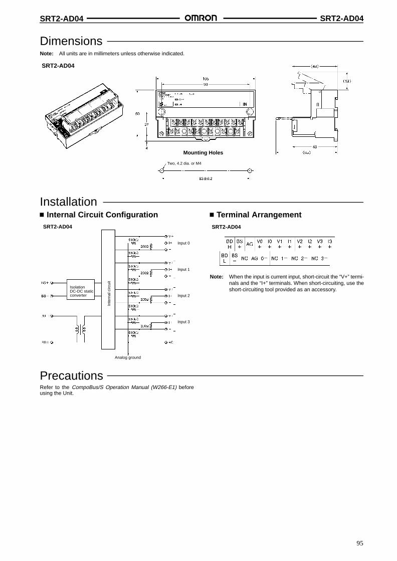
SRT2-AD04 SRT2-AD04
95
DimensionsNote: All units are in millimeters unless otherwise indicated.
SRT2-AD04
Mounting Holes
Two, 4.2 dia. or M4
Installation Internal Circuit ConfigurationSRT2-AD04
Isolation DC-DC staticconverter
Inte
rnal
circ
uit
Input 0
Input 1
Input 2
Input 3
Analog ground
Terminal ArrangementSRT2-AD04
Note: When the input is current input, short-circuit the “V+” termi-nals and the “I+” terminals. When short-circuiting, use theshort-circuiting tool provided as an accessory.
PrecautionsRefer to the CompoBus/S Operation Manual (W266-E1) beforeusing the Unit.

96
Analog Output Terminal SRT2-DA02
Compact Analog Output Model is theSame Shape as 16-point Remote I/OTerminals
Two output points or 1 output point is selectable.
Resolution: 1/6,000
105 x 48 x 50 (W x H x D)
Ordering InformationClassification I/O points Model
Analog Output Terminal 1 or 2 (selectable with DIP switch) SRT2-DA02
Note: For details about connecting the SRT2-DA02 to the Master Unit, refer to page 25.
SpecificationsRatings
Output
Item Voltage output Current output
External output permissibleload resistance
5 kΩ min. 600 Ω max.
Output impedance 0.5 Ω max. ---
Resolution 1/6,000 (FS)
Total 25°C ±0.4% FSaccuracy –10 to 55°C ±0.8% FS
Conversion time 2 ms/2 points and 2 ms/1 point
Dielectric strength 500 VAC for 1 min between communications power supply, analog output, and communications terminals (see note)
Note: There is no insulation between analog outputs.
CharacteristicsCommunications power supply voltage 14 to 26.4 VDC (power supply possible from Special Flat Cable)
Current consumption (see note) 170 mA max.
Connection method Multi-drop method and T-branch method
Dielectric strength 500 VAC (between insulated circuits)
Noise immunity Conforms to IEC61000-4-4, 2 kV (power lines)
Vibration resistance 10 to 150 Hz, 1.0-mm double amplitude or 70 m/s2
Shock resistance 200 m/s2
Mounting strength No damage when 100 N pull load was applied in all directions
Terminal strength No damage when 100 N pull load was applied
Screw tightening torque 0.3 to 0.5 N m
Ambient temperature Operating: –10°C to 55°CStorage: –25°C to 65°C
Ambient humidity Operating: 25% to 85% (with no condensation)
Weight Approx. 100 g
Note: The above current consumption is the value with all points turned ON excluding the current consumption of the external load.

SRT2-DA02 SRT2-DA02
97
NomenclatureSRT2-DA02
Mounting Screw Holes
DIN Track Mounting Hook
Terminal Block
Indicators
IndicatorsIndicator Name Color Display Meaning
PWR Power supply Green Lit The communications power supply is ON.
Not lit The communications power supply is OFF.
COMM Communication Yellow Lit Normal communications
Not lit A communications error has occurred or the Unit is in standby status.
ERR Communication Red Lit A communications error has occurred.error Not lit Normal communications or the Unit is in standby status.
U.ERR Unit error Red Lit An error has occurred in the Unit.
Not lit A communications error has occurred or the Unit is in standby status.
DIP Switch (SW101)(Open cover to access.)
Pin 1 Be sure to turn OFF.
Pin 2 Output points
OFF 2 points (default setting)
ON 1 point (output 0 enabled)
Pin 3 Communications mode
OFF High-speed communications (default setting)
ON Long-distance communications
Pin 4 Be sure to turn OFF.
Pin No. Node addresses
Pin 5 23
Pin 6 22
Pin 7 21
Pin 8 20
The default setting is for all of these switches to be OFF.
DIP Switch (SW102)(Open cover to access.)
Pin 1 Pin 2 Pin 3 Range for output 0
Pin 4 Pin 5 Pin 6 Range for output 1
OFF OFF OFF 0 to 5 (V) (default setting)
ON OFF OFF 1 to 5 (V)
OFF ON OFF 0 to 10 (V)
ON ON OFF –10 to 10 (V)
OFF OFF ON 4 to 20 (mA)
Do not make any settings other than the ones listed above.
Pin 7 Pin 8 Output during communications error
OFF OFF Clear at the output lower limit whencommunications error occurs. (defaultsetting)
OFF ON Clear at the output upper limit whencommunications error occurs.
ON OFF Clear at the output lower limit whencommunications error occurs (however, ifthe range is –10 to 10 V, the output will be0).
ON ON Output held when communications erroroccurs.
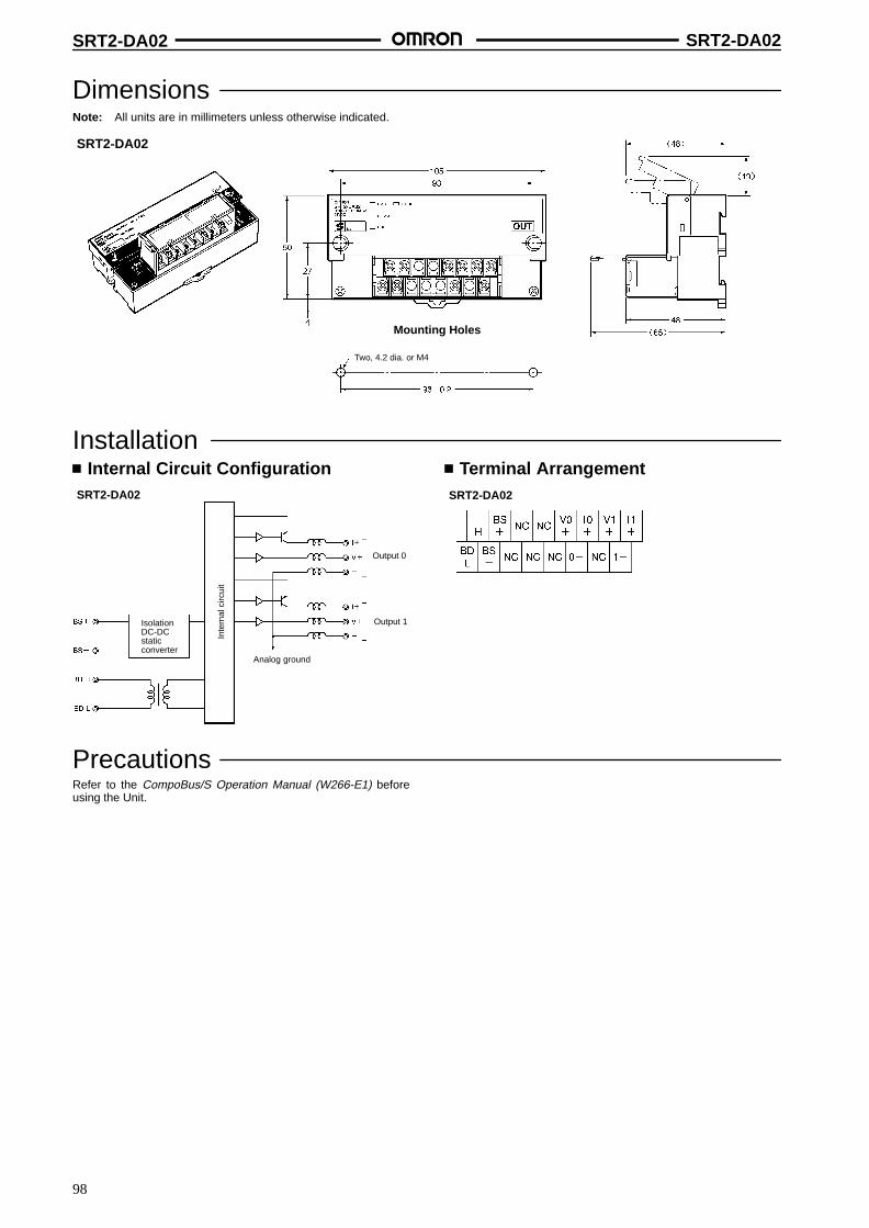
SRT2-DA02 SRT2-DA02
98
DimensionsNote: All units are in millimeters unless otherwise indicated.
SRT2-DA02
Mounting Holes
Two, 4.2 dia. or M4
Installation Internal Circuit Configuration
SRT2-DA02
IsolationDC-DCstaticconverter
Inte
rnal
circ
uit
Output 0
Output 1
Analog ground
Terminal ArrangementSRT2-DA02
PrecautionsRefer to the CompoBus/S Operation Manual (W266-E1) beforeusing the Unit.

99
Remote I/O Modules SRT2-ID16P/OD16P
Module Type that Allows PCB Mounting
Compact size at 60 x 16 x 35 (W x H x D)
Lineup now includes the 16-point input model and16-point output model.
Ordering InformationI/O classification Internal I/O circuit common I/O points Rated voltage I/O rated voltage Model
Input NPN (+ common) 16 24 VDC 24 VDC SRT2-ID16P
Output NPN (– common) SRT2-OD16P
SpecificationsRatings
Input (SRT2-ID16P)
Input current 2 mA max./point
ON delay time 1.5 ms max.
OFF delay time 1.5 ms max.
ON voltage 15 VDC min. between each input terminal and BS+ terminal
OFF voltage 5 VDC max. between each input terminal and BS + terminal
Output (SRT2-OD16P)
Rated output current 0.2 A/point, 0.6 A/common
Residual voltage 0.6 V max. between each output terminal and G terminal at 0.2 A
Leakage current 0.1 mA max. between each output terminal and G terminal at 24 VDC
CharacteristicsCommunications power supply voltage 20.4 to 26.4 VDC
I/O power supply voltage 24 VDC +10%/–15%
Current consumption (see note) 60 mA max.
Connection method Multi-drop method and T-branch method
Connecting Units 8 Input Terminals and 8 Output Terminals per Master
Dielectric strength 500 VAC for 1 min (1-mA sensing current between insulated circuits)
5-V output current 20 mA max. (5 V 0.5 V)
LED drive current (COMM, ERR) 10 mA max. (5 VDC)
SW carry current (ADR0 to 3, HOLD)
1 mA max.
Ambient temperature Operating: 0°C to 55°C (with no icing or condensation)Storage: –20°C to 65°C (with no icing or condensation)
Ambient humidity Operating: 35% to 85%
Weight 35 g max.
Note: The above current consumption is the value with all points turned ON excluding the current consumption of the external sensor con-nected to the input model and the current consumption of the load connected to the output model.

SRT2-ID16P/OD16P SRT2-ID16P/OD16P
100
DimensionsNote: All units are in millimeters unless otherwise indicated.
SRT2-ID16PSRT2-OD16P
Incorrect insertionprevention pin
PCB dimensions (top view)
No cumulative tolerance allowed
1.6 dia.
2.2 dia. +0.10
32-0.9 dia. +0.10
Installation Internal Circuit Configuration
SRT2-ID16P SRT2-OD16P
Inte
rnal
circ
uit
Inte
rnal
circ
uit
External Connections
Communications
Two-wireproximitysensor
BS– or G
Input Module (SRT2-ID16P) Output Module (SRT2-OD16P)Communications
Relay
Inte
rnal
circ
uit
Inte
rnal
circ
uit
D1: Reverse voltage prevention diode
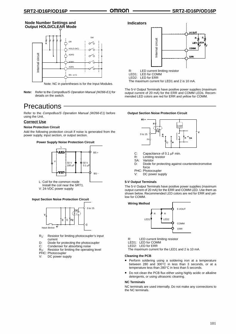
SRT2-ID16P/OD16P SRT2-ID16P/OD16P
101
Note: NC in parentheses is for the Input Modules.
Node Number Settings andOutput HOLD/CLEAR Mode
Inte
rnal
circ
uit
BS– or G
ADR1
ADR2
ADR3
HOLD (NC)
DR
SW
Note: Refer to the CompoBus/S Operation Manual (W266-E1) fordetails on the switch.
Indicators
R: LED current limiting resistorLED1: LED for COMMLED2: LED for ERRThe maximum current for LED1 and 2 is 10 mA.
Inte
rnal
circ
uit
The 5-V Output Terminals have positive power supplies (maximumoutput current of 20 mA) for the ERR and COMM LEDs. Recom-mended LED colors are red for ERR and yellow for COMM.
PrecautionsRefer to the CompoBus/S Operation Manual (W266-E1) beforeusing the Unit.
Correct UseNoise Protection CircuitAdd the following protection circuit if noise is generated from thepower supply, input section, or output section.
Power Supply Noise Protection Circuit
L: Coil for the common mode Install the coil near the SRT1.V: 24-VDC power supply
50 V 100 µF
50 V 0.1 µF
BS
L
V
BS
Input Section Noise Protection Circuit
R1: Resistor for limiting photocoupler’s inputcurrent
D: Diode for protecting the photocouplerC: Condenser for absorbing noiseR2: Resistor for limiting the operating levelPHC: PhotocouplerV: DC power supply
Input device
0 to 15
Output Section Noise Protection Circuit
C: Capacitance of 0.1 µF min.R: Limiting resistorSA: VaristorD: Diode for protecting against counterelectromotive
forcePHC: PhotocouplerV: DC power supply
Load
0 to 15
5-V Output TerminalsThe 5-V Output Terminals have positive power supplies (maximumoutput current of 20 mA) for the ERR and COMM LED. Use them asshown below. Recommended LED colors are red for ERR and yel-low for COMM.
Wiring Method
R: LED current limiting resistorLED1: LED for COMMLED2: LED for ERRThe maximum current for the LED1 and 2 is 10 mA.
LED1
R R
5 VOUT
COMM
ERR
LED2
Cleaning the PCB• Perform soldering using a soldering iron at a temperature
between 280 and 300°C in less than 3 seconds, or at atemperature less than 280°C in less than 5 seconds.
• Do not clean the PCB flux either using highly acidic or alkalinedetergents, or using ultrasonic cleaning.
NC TerminalsNC terminals are used internally. Do not make any connections tothe NC terminals.

102
Position Drivers FND-X-SRT
Advanced Servodrivers with PositionerFunctions
DIO and CompoBus/S Models are NewlyAdded
Servodriver and positioner are combined into oneUnit.
Conventional U-series, U-series UE type, H-series,and M-series AC Servomotors can be used.
Feeder control/DTP control and single operation/automatic incremental/continuous operation areavailable.
Easy to set, operate, and adjust.
Ordering InformationSpecifications Model
CompoBus/S models For 200-VAC input 6 A FND-X06H-SRTp p
12 A FND-X12H-SRT
25 A FND-X25H-SRT
50 A FND-X50H-SRT
For 100-VAC input 6 A FND-X06L-SRTp
12 A FND-X12L-SRT
Note: For details, refer to OMNUC FND-X-series User’s Manual (I524).
SpecificationsGeneral Specifications
Ambient temperature Operating: 0°C to 55°CStorage: –10°C to 70°C
Ambient humidity Operating: 35% to 90% (with no icing)Storage: 35% to 90% (with no icing)
Operating atmosphere No corrosive gases
Dielectric strength 1,500 VACRMS for 1 min at 50/60 Hz
Insulation resistance 5 MΩ min. (at 500 VDC) between power input terminals and between the power terminal andthe case
Vibration resistance 10 to 150 Hz in X, Y, and Z directions with 0.10-mm single amplitude; acceleration: 9.8 m/s2
max.; time coefficient: 8 min; 4 sweeps
Shock resistance 98 m/s2 max., three times each in X, Y, and Z directions
Degree of protection Built into panel (IP00)
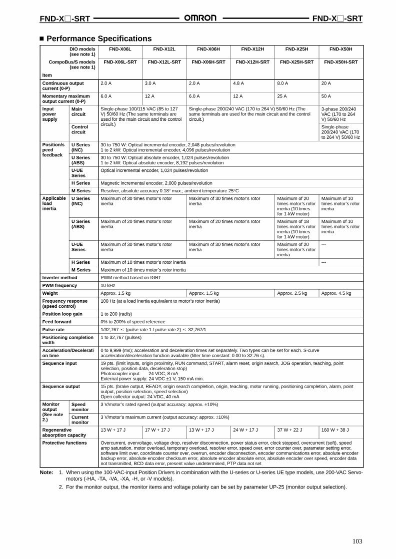
FND-X-SRT FND-X-SRT
103
Performance SpecificationsDIO models(see note 1)
FND-X06L FND-X12L FND-X06H FND-X12H FND-X25H FND-X50H
CompoBus/S models(see note 1)
Item
FND-X06L-SRT FND-X12L-SRT FND-X06H-SRT FND-X12H-SRT FND-X25H-SRT FND-X50H-SRT
Continuous outputcurrent (0-P)
2.0 A 3.0 A 2.0 A 4.8 A 8.0 A 20 A
Momentary maximumoutput current (0-P)
6.0 A 12 A 6.0 A 12 A 25 A 50 A
Inputpowersupply
Maincircuit
Single-phase 100/115 VAC (85 to 127V) 50/60 Hz (The same terminals areused for the main circuit and the controli it )
Single-phase 200/240 VAC (170 to 264 V) 50/60 Hz (Thesame terminals are used for the main circuit and the controlcircuit.)
3-phase 200/240VAC (170 to 264V) 50/60 Hzsupply
Controlcircuit
used for the main circuit and the controlcircuit.)
circuit.)
Single-phase200/240 VAC (170to 264 V) 50/60 Hz
Position/speedf db k
U Series(INC)
30 to 750 W: Optical incremental encoder, 2,048 pulses/revolution1 to 2 kW: Optical incremental encoder, 4,096 pulses/revolutionpeed
feedback U Series(ABS)
30 to 750 W: Optical absolute encoder, 1,024 pulses/revolution1 to 2 kW: Optical absolute encoder, 8,192 pulses/revolution
U-UESeries
Optical incremental encoder, 1,024 pulses/revolution
H Series Magnetic incremental encoder, 2,000 pulses/revolution
M Series Resolver, absolute accuracy 0.18° max.; ambient temperature 25°CApplicableloadinertia
U Series(INC)
Maximum of 30 times motor’s rotorinertia
Maximum of 30 times motor’s rotorinertia
Maximum of 20times motor’s rotorinertia (10 timesfor 1-kW motor)
Maximum of 10times motor’s rotorinertia
U Series(ABS)
Maximum of 20 times motor’s rotorinertia
Maximum of 20 times motor’s rotorinertia
Maximum of 18times motor’s rotorinertia (10 timesfor 1-kW motor)
Maximum of 10times motor’s rotorinertia
U-UESeries
Maximum of 30 times motor’s rotorinertia
Maximum of 30 times motor’s rotorinertia
Maximum of 20times motor’s rotorinertia
---
H Series Maximum of 10 times motor’s rotor inertia ---
M Series Maximum of 10 times motor’s rotor inertia
Inverter method PWM method based on IGBT
PWM frequency 10 kHz
Weight Approx. 1.5 kg Approx. 1.5 kg Approx. 2.5 kg Approx. 4.5 kg
Frequency response(speed control)
100 Hz (at a load inertia equivalent to motor’s rotor inertia)
Position loop gain 1 to 200 (rad/s)
Feed forward 0% to 200% of speed reference
Pulse rate 1/32,767 (pulse rate 1 / pulse rate 2) 32,767/1
Positioning completionwidth
1 to 32,767 (pulses)
Acceleration/Deceleration time
0 to 9,999 (ms); acceleration and deceleration times set separately. Two types can be set for each. S-curveacceleration/deceleration function available (filter time constant: 0.00 to 32.76 s).
Sequence input 19 pts. (limit inputs, origin proximity, RUN command, START, alarm reset, origin search, JOG operation, teaching, pointselection, position data, deceleration stop)Photocoupler input: 24 VDC, 8 mAExternal power supply: 24 VDC ±1 V, 150 mA min.
Sequence output 15 pts. (brake output, READY, origin search completion, origin, teaching, motor running, positioning completion, alarm, pointoutput, position selection, speed selection)Open collector output: 24 VDC, 40 mA
Monitoroutput(S t
Speedmonitor
3 V/motor’s rated speed (output accuracy: approx. ±10%)output(See note2.) Current
monitor3 V/motor’s maximum current (output accuracy: approx. ±10%)
Regenerativeabsorption capacity
13 W + 17 J 17 W + 17 J 13 W + 17 J 24 W + 17 J 37 W + 22 J 160 W + 38 J
Protective functions Overcurrent, overvoltage, voltage drop, resolver disconnection, power status error, clock stopped, overcurrent (soft), speedamp saturation, motor overload, temporary overload, resolver error, speed over, error counter over, parameter setting error,software limit over, coordinate counter over, overrun, encoder disconnection, encoder communications error, absolute encoderbackup error, absolute encoder checksum error, absolute encoder absolute error, absolute encoder over speed, encoder datanot transmitted, BCD data error, present value undetermined, PTP data not set
Note: 1. When using the 100-VAC-input Position Drivers in combination with the U-series or U-series UE type models, use 200-VAC Servo-motors (-HA, -TA, -VA, -XA, -H, or -V models).
2. For the monitor output, the monitor items and voltage polarity can be set by parameter UP-25 (monitor output selection).

FND-X-SRT FND-X-SRT
104
DimensionsNote: All units are in millimeters unless otherwise indicated.
200-VAC FND-X06H-SRT/-X12H-SRT100-VAC FND-X06L-SRT/-X12L-SRT
200-VAC FND-X25H-SRT
80
68 150
158
170
Three, 6 dia.
158
68
Three, M5
Mounting Holes
Mounting Holes119
150 107
158
170
Three, 6 dia. Three, M5
107
158
200-VAC FND-X50H-SRTMounting Holes
Four, 6 dia. Four, M5

105
Peripheral DevicesSpecial Flat Cable AllowsCommunication Path Extensionand T-branching with Ease
Ordering InformationVCTF Cable Products
Product Appearance Model Specification
Terminal-block Terminator SRS1-T Resistance: 100 Ω
T-branch Connector XS2R-D427-5 Used to branchcommunications lines andpower lines.(Waterproof specifications)
Connector Terminator (plug) SRS2-1 Waterproof terminatingresistance
Special Flat Cable ProductsProduct Appearance Model Specification
Branch Connector SCN1-TH4 Used with Special Flat Cable.
Extension Connector SCN1-TH4E Used with Special Flat Cable.
Connector Terminator SCN1-TH4T Used with Special Flat Cable.
Special Flat Cable SCA1-4F10 100 m
Note: Branch Connectors and Extension Connectors are sold in blocks of 10 Units.
Four-core VCTF Cable ProductsProduct Appearance Model Specification
Assembling Connector XS2C-D4S7 Communications connector plugfor 4-conductor VCTF cable
XS2G-D4S7 Communications connector socketfor 4-conductor VCTF cable
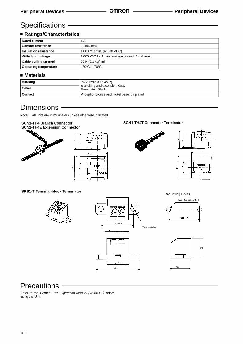
Peripheral Devices Peripheral Devices
106
Specifications Ratings/Characteristics
Rated current 4 A
Contact resistance 20 mΩ max.
Insulation resistance 1,000 MΩ min. (at 500 VDC)
Withstand voltage 1,000 VAC for 1 min, leakage current: 1 mA max.
Cable pulling strength 50 N (5.1 kgf) min.
Operating temperature –20°C to 70°C
MaterialsHousing PA66 resin (UL94V-2)
Branching and extension: GrayCover
Branching and extension: GrayTerminator: Black
Contact Phosphor bronze and nickel base, tin plated
DimensionsNote: All units are in millimeters unless otherwise indicated.
SCN1-TH4 Branch ConnectorSCN1-TH4E Extension Connector
SCN1-TH4T Connector Terminator
SRS1-T Terminal-block Terminator
40
Two, 4.4 dia.
30±0.2
Two, 4.2 dia. or M4
20
20
Mounting Holes
PrecautionsRefer to the CompoBus/S Operation Manual (W266-E1) beforeusing the Unit.
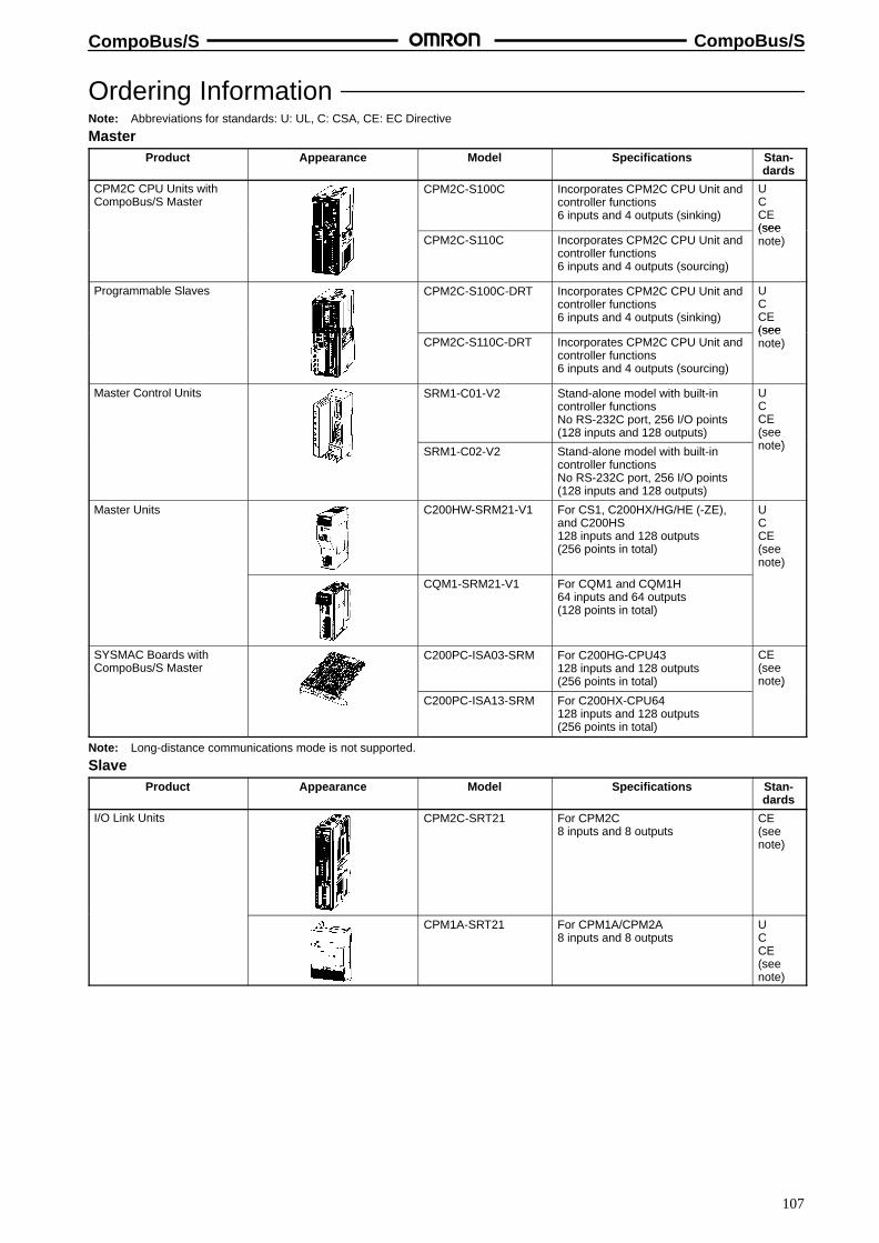
CompoBus/S CompoBus/S
107
Ordering InformationNote: Abbreviations for standards: U: UL, C: CSA, CE: EC Directive
MasterProduct Appearance Model Specifications Stan-
dards
CPM2C CPU Units withCompoBus/S Master
CPM2C-S100C Incorporates CPM2C CPU Unit andcontroller functions6 inputs and 4 outputs (sinking)
UCCE(see
CPM2C-S110C Incorporates CPM2C CPU Unit andcontroller functions6 inputs and 4 outputs (sourcing)
(seenote)
Programmable Slaves CPM2C-S100C-DRT Incorporates CPM2C CPU Unit andcontroller functions6 inputs and 4 outputs (sinking)
UCCE(see
CPM2C-S110C-DRT Incorporates CPM2C CPU Unit andcontroller functions6 inputs and 4 outputs (sourcing)
(seenote)
Master Control Units SRM1-C01-V2 Stand-alone model with built-incontroller functionsNo RS-232C port, 256 I/O points(128 inputs and 128 outputs)
UCCE(see
t )SRM1-C02-V2 Stand-alone model with built-incontroller functionsNo RS-232C port, 256 I/O points(128 inputs and 128 outputs)
(note)
Master Units C200HW-SRM21-V1 For CS1, C200HX/HG/HE (-ZE),and C200HS128 inputs and 128 outputs(256 points in total)
UCCE(seenote)
CQM1-SRM21-V1 For CQM1 and CQM1H64 inputs and 64 outputs(128 points in total)
SYSMAC Boards withCompoBus/S Master
C200PC-ISA03-SRM For C200HG-CPU43128 inputs and 128 outputs(256 points in total)
CE(seenote)
C200PC-ISA13-SRM For C200HX-CPU64128 inputs and 128 outputs(256 points in total)
)
Note: Long-distance communications mode is not supported.
SlaveProduct Appearance Model Specifications Stan-
dards
I/O Link Units CPM2C-SRT21 For CPM2C8 inputs and 8 outputs
CE(seenote)
CPM1A-SRT21 For CPM1A/CPM2A8 inputs and 8 outputs
UCCE(seenote)

CompoBus/S CompoBus/S
108
Product Stan-dards
SpecificationsModelAppearance
Transistor Remote I/OTerminals
SRT2-ID04SRT2-ID04-1SRT2-OD04SRT2-OD04-1
4 NPN inputs (+ common)4 PNP inputs (– common)4 NPN outputs (– common)4 PNP outputs (+ common)
UCCE(see
t )SRT2-ID08SRT2-ID08-1SRT2-OD08SRT2-OD08-1
8 NPN inputs (+ common)8 PNP inputs (– common)8 NPN outputs (– common)8 PNP outputs (+ common)
(note)
SRT2-ID16SRT2-ID16-1SRT2-OD16SRT2-OD16-1
16 NPN inputs (+ common)16 PNP inputs (– common)16 NPN outputs (– common)16 PNP outputs (+ common)
Transistor Remote I/OTerminals with 3-tierTerminal Block
SRT2-ID16TSRT2-ID16T-1SRT2-MD16TSRT2-MD16T-1SRT2-OD16TSRT2-OD16T-1
16 NPN inputs (+ common)16 PNP inputs (– common)16 NPN I/O points(inputs: + common;outputs: – common)16 PNP I/O points(inputs: – common;outputs: + common)16 NPN outputs (– common)16 PNP outputs (+ common)
UCCE(seenote)
Relay-mounted Remote I/OT i l
SRT2-ROC08 8 relay outputs UC
yTerminals SRT2-ROC16 16 relay outputs C
CESRT2-ROF08 8 power MOS FET relay outputs
CE(see
SRT2-ROF16 16 power MOS FET relay outputs(seenote)
Transistor Remote I/OTerminals with Connectors
SRT2-ID32MLSRT2-ID32ML-1
32 NPN transistor inputs(+ common)32 PNP transistor inputs(– common)
CE(seenote)
SRT2-OD32MLSRT2-OD32ML-1SRT2-MD32MLSRT2-MD32ML-1
32 NPN transistor outputs(– common)32 PNP transistor outputs(+ common)32 NPN transistor I/O points (inputs:+ common; outputs: – common)32 PNP transistor I/O points (inputs:– common; outputs: + common)
SRT2-VID08SSRT2-VID08S-1SRT2-VOD08SSRT2-VOD08S-1
8 NPN transistor inputs (+ common)8 PNP transistor inputs (– common)8 NPN transistor outputs(– common)8 PNP transistor outputs(+ common)
UCCE(seenote)
SRT2-VID16MLSRT2-VID16ML-1SRT2-VOD16MLSRT2-VOD16ML-1
16 NPN transistor inputs(+ common)16 PNP transistor inputs(– common)16 NPN transistor outputs(– common)16 PNP transistor outputs(+ common)
--- SRT2-ATT01SRT2-ATT02
Mounting hook AMounting hook B

CompoBus/S CompoBus/S
109
Product Stan-dards
SpecificationsModelAppearance
Waterproof TransistorTerminals
SRT2-ID04CLSRT2-ID04CL-1SRT2-OD04CLSRT2-OD04CL-1
4 NPN transistor inputs (+ common)4 PNP transistor inputs (– common)4 NPN transistor outputs(– common)4 PNP transistor outputs(+ common)
CE(seenote)
SRT2-ID08CLSRT2-ID08CL-1SRT2-OD08CLSRT2-OD08CL-1
8 NPN transistor inputs (+ common)8 PNP transistor inputs (– common)8 NPN transistor outputs(– common)8 PNP transistor outputs(+ common)
Sensor Terminals SRT2-ID08SSRT2-ND08SSRT2-OD08S
Sensor Terminals 8 inputs (NPN)4 automatic teaching points (NPN)8 outputs
---
CompoBus/S SensorAmplifier Terminals
SRT1-TID04SSRT1-TKD04S
4 communications points4 communications points (toconnect to the E3X-NM16)
---
SRT1-XID04SSRT1-XKD04S
4 expansion points4 expansion points (to connect tothe EX-NM16)
ConnectionUnits (seenote)
Photoelec-tric Sensors
E3X-NT16E3X-NT26E3X-NH16E3X-DA16
1-channel general-purpose teaching1-channel multi-functional,general-purpose teaching1-channel long-distance,high-precision bar-display teaching1-channel digital model
UCCE(seenote)
E3X-NM16 4-channel multi-functional,general-purpose teaching
ProximitySensors
E2CY-T16E2C-T16
Aluminum detectionCompact model with teachingfunction
UC
TerminalBlock Unit
E39-JID01 One input point ---
Analog Input Terminal SRT2-AD04 1 to 4 inputs (set with DIP switch) UCCE(see
t )Analog Output Terminal SRT2-DA02 1 or 2 outputs (set with DIP switch)
(note )
Remote I/O Modules SRT2-ID16PSRT2-OD16P
16 NPN inputs (+ common)16 NPN outputs (– common)
---
Position Drivers (forCompoBus/S)
FND-X06H-SRTFND-X12H-SRTFND-X25H-SRTFND-X50H-SRTFND-X06L-SRTFND-X12L-SRT
6 A at 200-VAC input12 A at 200-VAC input25 A at 200-VAC input50 A at 200-VAC input6 A at 100-VAC input12 A at 100-VAC input
UCE(seenote)cUL
Note: The Position Driver cannot be used in long-distance communications mode.
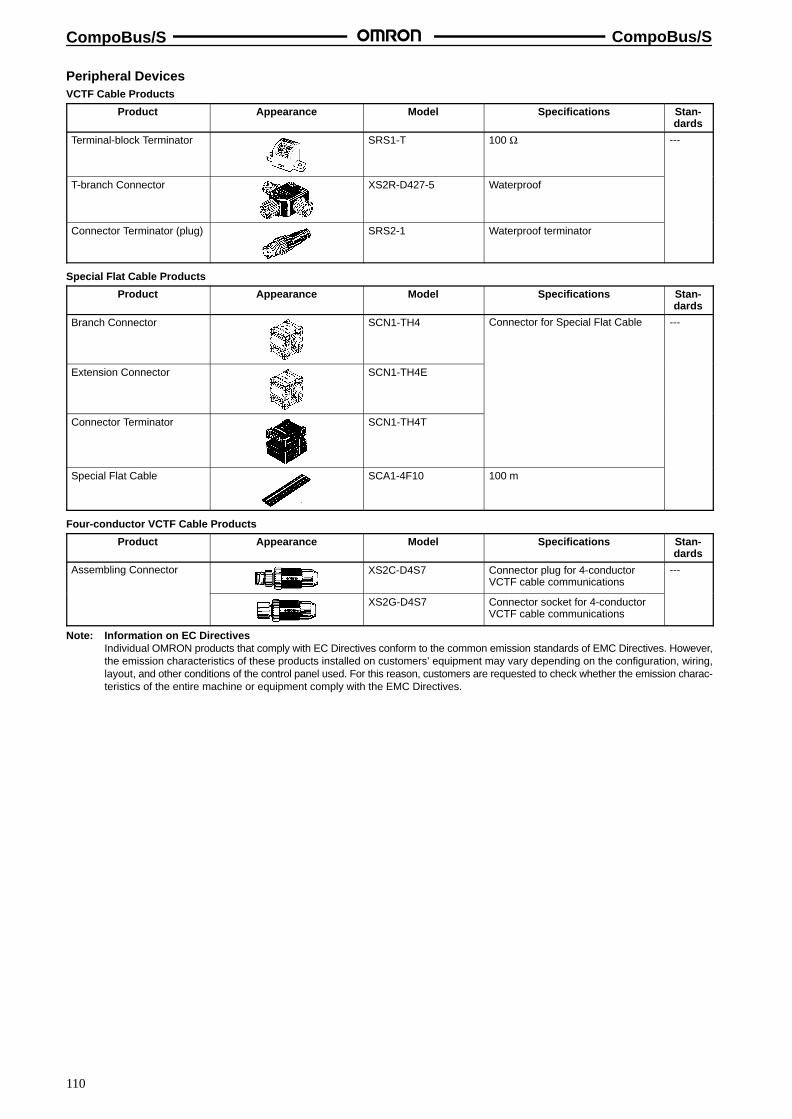
CompoBus/S CompoBus/S
110
Peripheral DevicesVCTF Cable Products
Product Appearance Model Specifications Stan-dards
Terminal-block Terminator SRS1-T 100 Ω ---
T-branch Connector XS2R-D427-5 Waterproof
Connector Terminator (plug) SRS2-1 Waterproof terminator
Special Flat Cable Products
Product Appearance Model Specifications Stan-dards
Branch Connector SCN1-TH4 Connector for Special Flat Cable ---
Extension Connector SCN1-TH4E
Connector Terminator SCN1-TH4T
Special Flat Cable SCA1-4F10 100 m
Four-conductor VCTF Cable Products
Product Appearance Model Specifications Stan-dards
Assembling Connector XS2C-D4S7 Connector plug for 4-conductorVCTF cable communications
---
XS2G-D4S7 Connector socket for 4-conductorVCTF cable communications
Note: Information on EC DirectivesIndividual OMRON products that comply with EC Directives conform to the common emission standards of EMC Directives. However,the emission characteristics of these products installed on customers’ equipment may vary depending on the configuration, wiring,layout, and other conditions of the control panel used. For this reason, customers are requested to check whether the emission charac-teristics of the entire machine or equipment comply with the EMC Directives.