new practices in mc safety - idc- · pdf filelets look at a simple diagram of a ... • the...
TRANSCRIPT
IDC Technologies: Safety in Automation Machinery Safety Systems
Page 1 of 30
IDC Technologies: Technical Papers on Safety in Automation
New Principles and Practices in Machinery Safety
D M Macdonald, IDC Technologies Ltd
Introduction
This technical paper provides a brief review of current practices in safety-related controls for machinery and outlines the role of engineering standards. It describes the development of new standards for applying programmable electronic systems and considers how these may change the methods used to specify and design safety controls. The paper is presented in 3 parts to provide a convenient format for persons accessing it on the IDC Website. These are: Part 1: Review of current practices in machinery safety controls. Part 2: Old and new standards, safety categories and SILs. Part 3: The impact of new standards for programmable safety systems Background IDC Technologies is a technology training company specializing in industrial training for engineers and technicians. It has established a wide range of workshop style training courses in the fields of electrical engineering, control systems and instrumentation, data communications and safety technology. David Macdonald, a qualified instrumentation and control engineer, has been involved with IDC over the past 4 years in the development and presentation of training workshops in Safety Instrumented Systems for the chemicals and process industries. The workshops are based on the application of the recently established international standards for safety systems, IEC 61508 and IEC 61511. IDC has conducted more than 30 such training workshops for clients in various countries including Australia, South Africa, UK and Canada. David is currently preparing a new training workshop in Machinery Safety Controls soon to be offered by IDC and this presentation is based on research done for the training course. Objectives of the paper: The first objective is to outline the range of practices in machinery safety controls leading to programmable systems and network-connected devices. The second objective is to show how and why the present method of classifying safety equipment by category is expected to be linked to the more universal method of classification using safety integrity levels (SILs).

IDC Technologies: Safety in Automation Machinery Safety Systems
Page 2 of 30
Part 1: Machinery safety controls and the role of PLCs. This part begins by outlining how machinery safety controls have evolved to utilize the power of programmable systems and networking. What is a machinery safety system? Any assembly of devices designed to protect people from hazards or injuries that could arise from the use of the machine can be considered to be a machinery safety system. The machinery safety system may also provide protection for the machine itself or other machines against damage due to malfunctioning of the machine. Lets look at a simple diagram of a machine with its basic control system and then see where the safety system fits in.
Figure 1:Generalized machine with basic control
The diagram here depicts a machine with a basic control system. It may for example have drives creating movements of assemblies and cutting tools, if it is an injection moulding machine it may have hydraulic pumps with hydraulic valves controlling linear actuators. The actions of the machine will have physical parameters that can be measured with sensors and evaluated by the control system. The control system will operate drives and actuators to follow a programme of actions that will be decided by the operator and/or the stored programme within the machine. In automation systems it may be that the machine controls will exchange data with a larger control network, enabling this machine to be operated in co-ordination with several other machines. Hence we must recognize that there are several sources of commands for the machine to respond with controlled actions. Sources of commands are:
• The operator via a control interface • The machine control logic from a fixed logic control or from a stored program • The automation cell control system
To these we must add “false commands” from malfunctions:
• The machine goes wrong, mechanically or electrically. • The operator does something wrong. • The control system goes wrong or is incorrectly programmed.
Machine
Machine Control System
MotionPositionSpeedTemperatureetc
Power
Actuators
Sensors
Operator Interface
OperatorAutomation Network
Materials Products
Machine with Basic Control System
No safety related parts are identified in this diagram
IDC Technologies: Safety in Automation Machinery Safety Systems
Page 3 of 30
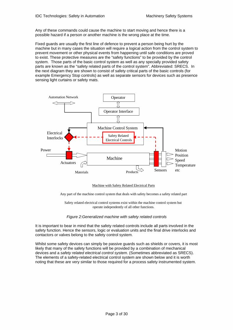
Any of these commands could cause the machine to start moving and hence there is a possible hazard if a person or another machine is the wrong place at the time. Fixed guards are usually the first line of defence to prevent a person being hurt by the machine but in many cases the situation will require a logical action from the control system to prevent movement or other physical events from happening until safe conditions are proved to exist. These protective measures are the “safety functions” to be provided by the control system. Those parts of the basic control system as well as any specially provided safety parts are known as the “safety related parts of the control system”. Abbreviated: SRECS. In the next diagram they are shown to consist of safety critical parts of the basic controls (for example Emergency Stop controls) as well as separate sensors for devices such as presence sensing light curtains or safety mats.
Figure 2:Generalized machine with safety related controls
It is important to bear in mind that the safety related controls include all parts involved in the safety function. Hence the sensors, logic or evaluation units and the final drive interlocks and contactors or valves belong to the safety control system. Whilst some safety devices can simply be passive guards such as shields or covers, it is most likely that many of the safety functions will be provided by a combination of mechanical devices and a safety related electrical control system. (Sometimes abbreviated as SRECS). The elements of a safety-related electrical control system are shown below and it is worth noting that these are very similar to those required for a process safety instrumented system.
Machine
Machine Control System
MotionPositionSpeedTemperatureetc
Power
Actuators
Sensors
Operator Interface
OperatorAutomation Network
Materials Products
Safety Related Electrical Controls
Machine with Safety Related Electrical Parts
Any part of the machine control system that deals with safety becomes a safety related part
Safety related electrical control systems exist within the machine control system but operate independently of all other functions.
ElectricalInterlocks
IDC Technologies: Safety in Automation Machinery Safety Systems
Page 4 of 30
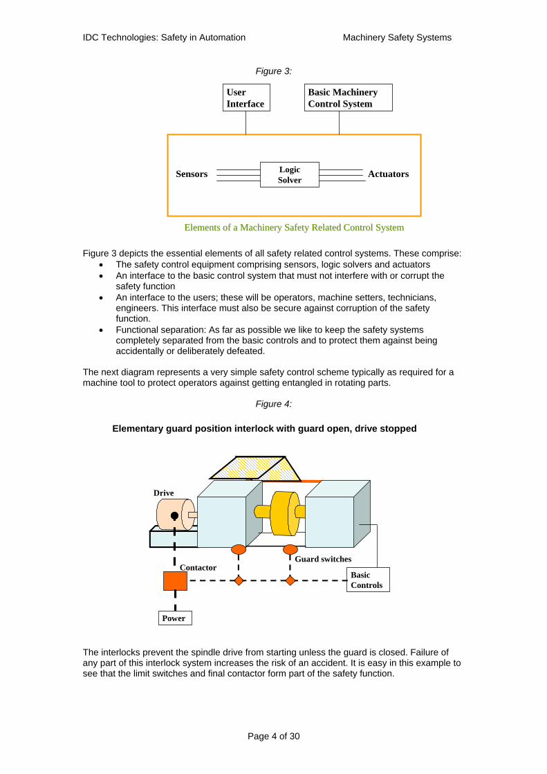
Figure 3:
Figure 3 depicts the essential elements of all safety related control systems. These comprise:
• The safety control equipment comprising sensors, logic solvers and actuators • An interface to the basic control system that must not interfere with or corrupt the
safety function • An interface to the users; these will be operators, machine setters, technicians,
engineers. This interface must also be secure against corruption of the safety function.
• Functional separation: As far as possible we like to keep the safety systems completely separated from the basic controls and to protect them against being accidentally or deliberately defeated.
The next diagram represents a very simple safety control scheme typically as required for a machine tool to protect operators against getting entangled in rotating parts.
Figure 4:
The interlocks prevent the spindle drive from starting unless the guard is closed. Failure of any part of this interlock system increases the risk of an accident. It is easy in this example to see that the limit switches and final contactor form part of the safety function.
Elements of a Machinery Safety Related Control SystemElements of a Machinery Safety Related Control System
LogicSolver
Sensors Actuators
UserInterface
Basic MachineryControl System
BasicControls
Power
Contactor
Drive
Elementary guard position interlock with guard open, drive stopped
Guard switches

IDC Technologies: Safety in Automation Machinery Safety Systems
Page 5 of 30
A typical hardware based implementation of the guard door safety function will link the guard door switches in series with an emergency stop switch to provide an input to a latching relay. The latching relay will trip when the guard door is opened or when the E-Stop is pressed. To improve the safety of the circuits an additional relay is used to prevent the latching relay from being reset unless the safety control circuits are healthy (i.e. free of dangerous faults). For example in figure 5 a simplified safety relay is shown where K3 is a relay that must be energized before the latching relay K1 can be set. K3 will not energize unless the power control contactor(s) C has been released, proving that it is not held in by another stray circuit or by a mechanical defect. In practice relay K1 is usually duplicated by a second channel or redundant relay K2 and both relays must be energized and latched to close the output circuits. K3 is often arranged with multiple contacts and expansion units to enable many drives to be interlocked from the same logic.
Figure 5
The example shown in figure 5 uses a safety monitoring relay unit to perform the essential logic functions required to provide safety integrity. These are: Checks on the state of input signals, detection of stuck contactors, wiring faults in the input and output circuits, timing and logic for interlocking control etc. The safety monitoring relay modules ensure that the safety interlocks and E-Stop functions are able to operate independently of the basic control system actions at all times. This is one of the most essential features of any safety control system.
K3K1
K1.2K3.1
E-Stop
K1.4
C1
24V dc
K1.1
MM
Start/stop control
24V dc0V dc
Tripped Indicator
Simplified E-Stop and Guard Switch Monitoring Relay
Reset
Open
C1
K1.3
Guard Door
Direct acting limit switch

IDC Technologies: Safety in Automation Machinery Safety Systems
Page 6 of 30
It has been common practice for many years to use safety relay modules in most basic machine safety applications and it has lead to the growth of a wide range of safety monitoring devices. Essentially these are packaged logic modules certified to be suitable for the standard protection functions. A generic model for these devices is shown in figure 6.
Figure 6 Monitoring relays, E-Stop relays and many adaptations of this principle are the workhorses of machinery safety practice and can be found in most machines typically used in manufacturing and automation. Control system equipment vendors offer a wide range of devices selectable for function and for safety category. With PLCs being the normal basic control device, the safety module interfaces between the output of the PLC and the final control elements (contactors) typically as shown in figure 7.
Figure 7 This configuration allows normal PLC control functions to be interlocked with a secure hardwired device performing the safety function. The safety device also provides contact inputs to the PLC to copy the states of sensors and to notify the status of the safety interlocks.
Monitorrelay Motor stop
control elements
Guard switchcircuits
InputInput OutputOutput
PLCPLCOperation with Operation with PLC basic controlPLC basic control
Functional Diagram of Monitoring Relay Application
Monitorrelay
Monitors switchcircuit for any single dangerous fault
Monitors itselffor any internal fault
Monitors contactorswhere two are used
Motor stopcontrol elements
Guard switchCircuits or E-Stops
Basic controlBasic control
Status Start/stop
Reset
Status

IDC Technologies: Safety in Automation Machinery Safety Systems
Page 7 of 30
The same arrangement is applied for Emergency Stops, presence detectors using light curtains, pressure sensitive mats, two hand controls, guard locking devices, rundown speed interlocks etc. Fig 7 also illustrates the point that it is essential to maintain the functional separation between basic controls and safety controls. It is essential to avoid the possibility that a fault that causes an accident is also able to defeat the safety function. Hence it is not acceptable to take away the safety related control circuits and place the logic in the basic control PLC. Why not perform the safety function in a separate but standard PLC? As PLCs became the norm for control, machinery builders became tempted to execute safety logic using a basic control PLC. This practice is not acceptable for several reasons including the following:
• Failure modes of the standard PLC are unpredictable, particularly when combined
with software driven responses. • Fail-safe response is not assured due to a lack of diagnostics to detect and handle
dangerous faults •• Vulnerable to systematic errors in software that cannot be found by testing. • No limitations on application programming, hence unproven logic paths can be
created. • Lack of security against program corruption.
In a review of the position regarding standard PLCs compared with safety PLCs, industry specialist Dr William M Goble concluded:
“The realization of many users that conventional controllers cannot be depended upon in critical protection applications creates the need for safety PLCs. The standards are high for safety PLC design, manufacture and installation. Anything less that these high standards will soon be considered irresponsible, if not negligent, from a business, professional and social point of view.”
From a paper by Dr. William M. Goble, Exida, www.exida.com This is basically the case for vendors to produce a special purpose PLC built specifically for critical safety applications. Lets look at what it takes.
Characteristics of Safety PLCs The answer to the problem of undetected faults in PLCs lies in the concepts of Fault Coverage and Fault Tolerant Systems: The answer to the problem of hidden defects in software is high quality embedded (i.e. operating system) software combined with strictly defined and constrained user programming facilities. (Sometimes described as limited variability languages) Safety device manufacturers soon began to develop specialized safety PLCs that would overcome the objections and meet the requirements we have described above.
Characteristics of a safety PLC
• Automatic diagnostics continuously check the PLC system functions at short intervals within the fault tolerant time of the process.
• High diagnostic coverage means that at least 99% of all hardware faults will be detected and notified for attention and repair.
• Provides a predictable and safe response to all failures of hardware, power supplies and system software
• Fault injection testing of the complete design is performed to ensure safe failure

IDC Technologies: Safety in Automation Machinery Safety Systems
Page 8 of 30
response to all known faults
• I/O subsystems continuously check all signal channels. I/O bus communications are self-checking; faults result in safe isolation of affected I/O groups.
• High security on any reading and writing via a digital communications port.
Software characteristics of a safety PLC
Software quality assurance methods are deployed throughout the development and testing of both operating system and application software development. Software development takes place under “safety life cycle “ procedures as specified in IEC 61508 part 3. The software design and testing is fully documented so that third-party inspectors can understand PLC operation.
• Operating system uses a number of special techniques to ensure software reliability. These include:
“Program flow control” checking, this insures that essential functions execute in the correct sequence.
“Data verification” stores all critical data redundantly in memory and checks validity before use
• Operating system and user application software tools are approved for safety by third party approval bodies.
• Operating system and programming package supplied by same vendor as the hardware.
• Software and hardware integration tested by approval bodies
• Extensive analysis and testing carefully examines operating systems for task interaction.
• Application software uses “Limited variability languages” to restrict to end users to working within a framework of well-proven instructions and function blocks.
• All application software updated transparently to redundant channels
Whilst all of the above are general performance and qualification features of the safety PLCs the practical end user will also be interested in some more down to earth characteristics. For example users will look for:
• Economically priced PLCs at the right size for typical machine applications.
• Input channels suitable for all common safety sensors and output channels suitable for connection to secondary or final control contactors or solenoids.
• Remote I/O capabilities to allow input and output modules to be mounted close to the parts of the machine or production line that they serve
• Speed of response fast enough to deliver E-Stop and safety trip responses without increasing risks to persons.
• Low software engineering costs, library of certified safety function blocks.
• Easy to program with fill-in-the blanks function blocks plus simple ladder logic or sequential logic instructions. Program language should be a close as possible to the type in use for basic control PLCs.
• Good testing facilities
• Rapid identification of faulty parts and easy replacement
• Compatible but safe connections to automation control networks.

IDC Technologies: Safety in Automation Machinery Safety Systems
Page 9 of 30
In other words it will be best if the safety PLC is, in all respects except safety, the same product for the end user as the standard PLC.
Examples of typical safety PLC arrangements are shown in the next figures. These diagrams are conceptual and are used only for simplified illustrations. Manufacturer’s application guides should be consulted for accurate details of possible schemes.
Figure 8
Siemens S95F Figure 8 shows a Siemens S95F dual redundant safety PLC arranged to provide all safety control functions whilst interchanging data with a separate basic control PLC. All commands from the basic PLC that require safety overrides or interlocks passed through the safety PLC for action subject to safety constraints. The safety PLC provides all input and output safety diagnostics and fault detection logic for the sensors wiring and for the condition of the final drive elements such as contactors or hydraulic valves. All safety logic is configured in software function blocks that have been designed and tested for safety integrity. PILZ PSS This next example shows a PILZ PSS safety controller. This is a 1oo3 architecture using 3 different types of processor with 3 different types of compiler having dissimilar units the possibilities of common cause failures affecting two or three processors at the same time are virtually eliminated. The processors compare data values between themselves to identify any mismatches and all 3 outputs must agree on any decision to energize an output signal. The PILZ controller is supplied with safety certified software including function-specific applications that are approved for particular tasks such as E-stop or two hand controls. Some blocks are approved for complete power press safety interlocking functions.
Machine Control System
Sensors
Operator Interface
Operator
Automation Network
Non-safety control
S5-95F
Machine with 1oo2 Safety PLC
Control PLC
SafetySensorsSafety control
S5-95F

IDC Technologies: Safety in Automation Machinery Safety Systems
Page 10 of 30
Figure 9 PILZ PSS Safety Controller
Single channel safety PLCs More recently manufacturers have been introducing single channel non-redundant safety certified PLCs to serve the smaller and simpler machinery applications found in large numbers in factories. The IEC 615108 standard sets out the requirements for safety integrity in PES hardware in very flexible way. For SIL 1 and SIL 2 applications it is acceptable to operate with single channel architectures provided the level of diagnostic coverage is sufficiently high. This has encouraged the growth of small single channel safety controllers. Safe networking The next step in the growth of safety systems was the introduction of safe networking. This evolution follows the same rationale as for any automation network, the attraction being that it increases the scope and power of any control system without adding the complexity of multiple wiring connections in hardware. The development of safe networks has been based on the principles laid down in the programmable system standards DIN 19250 and IEC 61508. These standards focus on achieving high integrity through intensive diagnostics and high quality software engineering combined with fail-safe techniques. Networks are able to comply with the performance requirements defined by these standards for SIL ratings even in single channel designs. Clearly there are some essential requirements for a field-bus network to be used in safety:
• The network must guarantee delivery of data packets in a minimum time frame. • All devices connected to the network must be guaranteed to fail to a safe condition if
a network fault is detected. • Network diagnostics must be capable of detecting virtually all (more than 99%) of
conceivable errors in sufficient time to avoid a dangerous fault being present on the network.
• All devices on the network must be known to be present and must be polled to confirm their safe status.
• Single channel networks must deliver good availability to avoid spurious downtime.
Processor Processor
AA
I Register 1I Register 1
O Register 1 O Register 1
Processor Processor
AA
I Register 1I Register 1
O Register 1 O Register 1
Processor Processor
BB
I Register 2I Register 2
O Register 2 O Register 2
Processor Processor
BB
I Register 2I Register 2
O Register 2 O Register 2
Processor Processor
CC
I Register 3I Register 3
O Register 3 O Register 3
Processor Processor
CC
I Register 3I Register 3
O Register 3 O Register 3
ANDAND
3 different3 differentmakesmakes
3 different3 differentcompilerscompilers
IDC Technologies: Safety in Automation Machinery Safety Systems
Page 11 of 30
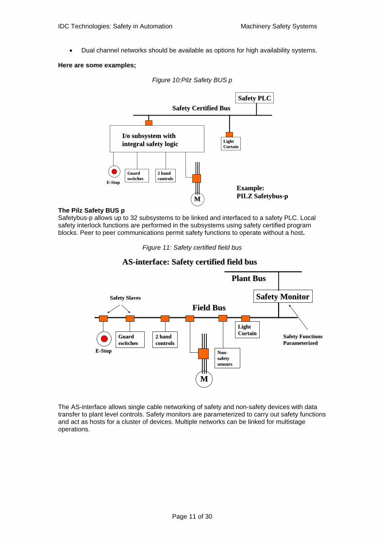
• Dual channel networks should be available as options for high availability systems. Here are some examples;
Figure 10:Pilz Safety BUS p
The Pilz Safety BUS p Safetybus-p allows up to 32 subsystems to be linked and interfaced to a safety PLC. Local safety interlock functions are performed in the subsystems using safety certified program blocks. Peer to peer communications permit safety functions to operate without a host.
Figure 11: Safety certified field bus
The AS-interface allows single cable networking of safety and non-safety devices with data transfer to plant level controls. Safety monitors are parameterized to carry out safety functions and act as hosts for a cluster of devices. Multiple networks can be linked for multistage operations.
Guard Guard switches switches
2 hand 2 hand controlscontrols
EE--StopStop
I/o subsystem with I/o subsystem with integral safety logicintegral safety logic
MM
Safety PLCSafety PLCSafety Certified BusSafety Certified Bus
Example:Example:PILZ SafetybusPILZ Safetybus--pp
Light Light CurtainCurtain
ASAS--interface: Safety certified field businterface: Safety certified field bus
Guard Guard switches switches
2 hand 2 hand controlscontrols
EE--StopStop
MM
Safety MonitorSafety MonitorField BusField Bus
Light Light CurtainCurtain
Plant BusPlant Bus
Safety SlavesSafety Slaves
Safety FunctionsSafety FunctionsParameterizedParameterized
NonNon--safety safety sensorssensors
IDC Technologies: Safety in Automation Machinery Safety Systems
Page 12 of 30
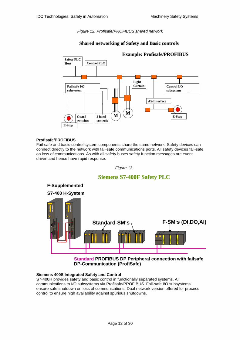
Figure 12: Profisafe/PROFIBUS shared network
Profisafe/PROFIBUS Fail-safe and basic control system components share the same network. Safety devices can connect directly to the network with fail-safe communications ports. All safety devices fail-safe on loss of communications. As with all safety buses safety function messages are event driven and hence have rapid response.
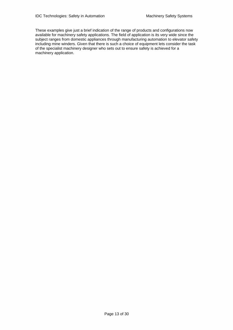
Figure 13
Siemens 400S Integrated Safety and Control S7-400H provides safety and basic control in functionally separated systems. All communications to I/O subsystems via Profisafe/PROFIBUS. Fail-safe I/O subsystems ensure safe shutdown on loss of communications. Dual network version offered for process control to ensure high availability against spurious shutdowns.
Shared networking of Safety and Basic controlsShared networking of Safety and Basic controls
Guard Guard switches switches
2 hand 2 hand controlscontrols
EE--StopStop
MM
Safety PLCSafety PLCHostHost
Example: Profisafe/PROFIBUSExample: Profisafe/PROFIBUS
Light Light CurtainCurtainFail safe I/OFail safe I/O
subsystemsubsystem
MM
Control PLCControl PLC
Control I/OControl I/Osubsystemsubsystem
ASAS--InterfaceInterface
EE--StopStop
Siemens Siemens S7S7--400F Safety PLC 400F Safety PLC
RUN-PRUN
STOPCMRES
RUN-PRUN
STOPCMRES
RUN-PRUN
STOPCMRES
RUN-PRUN
STOPCMRES
F-Supplemented S7-400 H-System
Standard-SM‘s F-SM‘s (DI,DO,AI)
Standard PROFIBUS DP Peripheral connection with failsafe DP-Communication (ProfiSafe)
IDC Technologies: Safety in Automation Machinery Safety Systems
Page 13 of 30
These examples give just a brief indication of the range of products and configurations now available for machinery safety applications. The field of application is its very wide since the subject ranges from domestic appliances through manufacturing automation to elevator safety including mine winders. Given that there is such a choice of equipment lets consider the task of the specialist machinery designer who sets out to ensure safety is achieved for a machinery application.
IDC Technologies: Safety in Automation Machinery Safety Systems
Page 14 of 30
Part 2: Old and new standards, safety categories and SILs. Having taken a brief look at the range of technologies now offered by manufacturers lets now consider the task of the designer of a machine or a production plant. To begin with we should take brief look at the design requirements laid down by engineering standards and consider the knowledge and experience resources available in such standards. Standards and regulations Machinery safety practices have become well established over many years using well-proven basic design principles. The industry is characterized by having to comply with detailed safety regulations for the protection of workers using machines. This in turn has led to a wide range of engineering standards being used to define safety requirements for machines in general whilst there are many standards defining essential protection methods for specific types of machine. In general, regulations require suppliers of machines to ensure that their products are safe to use whilst the owners of the machines are obliged to make sure that the machines are used in a safe manner. The end result is always that the safety of the machine is to be assured either by:
• Compliance with a known and specific safety standard or • Where no such standard exists the safety is established by following a set of design
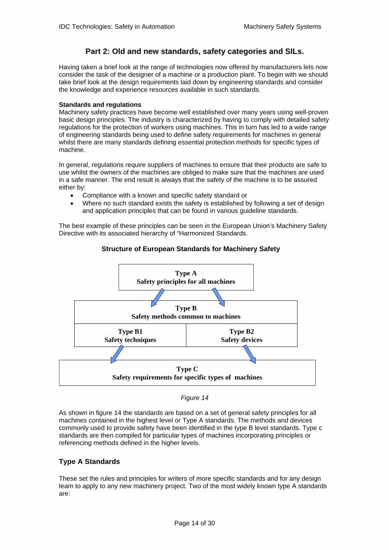
and application principles that can be found in various guideline standards. The best example of these principles can be seen in the European Union’s Machinery Safety Directive with its associated hierarchy of “Harmonized Standards.
Figure 14
As shown in figure 14 the standards are based on a set of general safety principles for all machines contained in the highest level or Type A standards. The methods and devices commonly used to provide safety have been identified in the type B level standards. Type c standards are then compiled for particular types of machines incorporating principles or referencing methods defined in the higher levels.
Type A Standards
These set the rules and principles for writers of more specific standards and for any design team to apply to any new machinery project. Two of the most widely known type A standards are:
Structure of European Standards for Machinery Safety
Type CSafety requirements for specific types of machines
Type BSafety methods common to machines
Type B1Safety techniques
Type B2Safety devices
Type BSafety methods common to machines
Type B1Safety techniques
Type B2Safety devices
Type ASafety principles for all machines

IDC Technologies: Safety in Automation Machinery Safety Systems
Page 15 of 30
• EN 292 parts 1 and 2: Safety of Machinery. Basic terminology, general design principles. Part 1 mainly handles the risks to be evaluated and the design principles to be used to reduce the risks. Part 2 outlines the basic principles of machinery guarding, interlocking, emergency stops, trip devices, safety distances etc
• EN 1050 Safety of Machinery, Principles of Risk Assessment. EN 1050 sets down methods for risk assessment that form the first essential stage in the development of protection systems for machinery
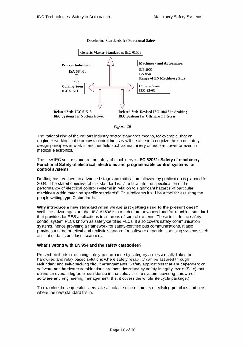
Type B Standards Type B 1 standards set down design requirements for safety techniques such as the provision of safety-related electrical controls. Examples relevant to control engineers are: EN 60204: Safety of machinery-Electrical equipment of machines parts 1 and 2 and EN 954: Safety of machinery-Safety related parts of control systems-parts 1 and 2. Type B2 standards deal with widely used safety devices such as light curtain detectors and two hand controls. Examples are: EN 418 for emergency stop switches and EN 61496 for the application of light barriers. Type C Standards A large number of type C standards have been produced to deal the hazards of specifically identified types of machines. The most common of these are the manufacturing plant machines beginning with power presses. Because these machine type standards have been prepared using the foundation of type A and B standards they will generally have a consistent basis for the safety requirements defined in their texts. For example, they will refer any devices suggested for safety guarding or emergency stops to the relevant type B standard. Obviously any new technology-driven developments influencing the type A or B level standards will have to be carefully introduced to this hierarchical system. Changing the ground rules is not going to be easy. New standards for programmable electronic systems in functional safety With the growth of programmable and networked safety related control systems came the realization that existing practices for hardware based safety controls were not adequate. There was an increasing risk that unsafe practices would be inadvertently introduced with the new programmable systems. For control engineers the most relevant and current standard is EN 954, which deals with the design and validation of safety related parts of a machinery control system. The design principles in this standard form the basis of most machinery electrical safety systems we see today. However this standard began life in the days when most safety controls were built with hardwired circuits and relay devices and it does not adequately deal with the complexities introduced by using programmable devices such as PLCs and communication networks into machinery controls. A way forward for the machinery safety world is to utilize the newly established standard IEC 61508 as a foundation for the management and design of machinery controls where programmable devices are used. This fits in with the intention to have a unified set of practices for functional safety across a wide range of industries. The philosophy supporting IEC 61508 is that it is a generic standard that leads to the development of more specific “industry sector” standards based on the same principles but adapted to the particular requirements of each industrial sector. Thus we see the current development of sector standards for functional safety using PES in process, machinery and nuclear energy industries as shown in fig 2 below
IDC Technologies: Safety in Automation Machinery Safety Systems
Page 16 of 30
Figure 15
The rationalizing of the various industry sector standards means, for example, that an engineer working in the process control industry will be able to recognize the same safety design principles at work in another field such as machinery or nuclear power or even in medical electronics. The new IEC sector standard for safety of machinery is IEC 62061: Safety of machinery-Functional Safety of electrical, electronic and programmable control systems for control systems Drafting has reached an advanced stage and ratification followed by publication is planned for 2004. The stated objective of this standard is…” to facilitate the specification of the performance of electrical control systems in relation to significant hazards of particular machines within machine specific standards”. This indicates it will be a tool for assisting the people writing type C standards. Why introduce a new standard when we are just getting used to the present ones? Well, the advantages are that IEC 61508 is a much more advanced and far-reaching standard that provides for PES applications in all areas of control systems. These include the safety control system PLCs known as safety-certified PLCs; it also covers safety communication systems, hence providing a framework for safety-certified bus communications. It also provides a more practical and realistic standard for software dependent sensing systems such as light curtains and laser scanners. What’s wrong with EN 954 and the safety categories? Present methods of defining safety performance by category are essentially linked to hardwired and relay based solutions where safety reliability can be assured through redundant and self-checking circuit arrangements. Safety applications that are dependent on software and hardware combinations are best described by safety integrity levels (SILs) that define an overall degree of confidence in the behavior of a system, covering hardware, software and engineering management. (I.e. it covers the whole life cycle package.) To examine these questions lets take a look at some elements of existing practices and see where the new standard fits in.
Developing Standards for Functional Safety
ISA S84.01
Coming SoonIEC 61511
Machinery and Automation
Generic Master Standard is IEC 61508
Process IndustriesEN 1050EN 954Range of EN Machinery Stds
Coming SoonIEC 62061
Related Std: IEC 61513 I&C Systems for Nuclear Power
Related Std: Revised ISO 10418 in draftingI&C Systems for Offshore Oil &Gas

IDC Technologies: Safety in Automation Machinery Safety Systems
Page 17 of 30
The designer’s tasks; The design procedures for safety measures are spelt out in standards EN 1050 and EN 954. IEC 62061 follows the same principles. The essential steps are:
1. Identify the hazards by various methods of hazard study. 2. Estimate the risks for each hazard and each activity at the machine. 3. Decide on the need for risk reduction. 4. Identify all safety functions required to protect persons and the equipment from harm
and define those provided by safety related electrical controls. 5. Determine the safety integrity requirements of each function in terms of a category (or
SIL rating when using IEC 62061) 6. Define the structure of the safety control function as a set of sub systems or
functional blocks. 7. Ensure that each sub-system is specified and engineered to the required SIL or
Category. 8. Carry out systematic validation of all designs and responses against original safety
requirements Identification of safety related parts In more complex applications it requires careful analysis to identify all the parts that are related to the safety function. For large machine tools or for assembly line automation the list of safety functions can become quite large, with many interactions between the basic controls and the safety controls, Once identified, all safety related parts become subject to the requirements of the relevant safety standards. For example in figure 16 the safety related parts of the controls deal with the guard door sensing, decide the logic and operate the final controls. The basic control function has been identified separately but its output must operate through the safety rated output stage to the contactor.
Figure 16
Design Issues: The key question for the safety related control system is “How good must it be? “ The simple answer to this is “ It depends how much risk reduction you need “. Risk reduction needs are identified as part of the process of risk assessment. This is the basis of all safety management procedures for both machinery and process plant safety practices. In theory, the risk reduction requirements can be obtained by an iterative design process as laid down in the type-A standard EN 1050. A simplified concept diagram here shows that the
Safety Control System Parts
(SRECS)(SRECS)
HazardHazardSensingSensing
Door SwitchDoor Switch
Overall Safety SystemOverall Safety System Final ProtectionFinal Protection
SensorSensor LogicLogic ActuatorActuatorDoorDoor DriveDrive
ContactorContactor
Door SwitchDoor Switch RelaysRelays ContactorContactor
Basic Control SystemBasic Control System

IDC Technologies: Safety in Automation Machinery Safety Systems
Page 18 of 30
procedure begins with the identification of hazards and the estimation of risk. Estimated risk is compared with what is considered to an acceptable or “tolerable” level of risk to determine the need if any for risk reduction.
Figure 17: Risk Assessment Procedure
It is at this point that the practices for process safety systems and machinery safety systems have taken different paths. Risk reduction scales in process plant safety Due to the generally more catastrophic nature of process plant accidents the risks there are often measured in quantitative terms such 1 death per 100 years.
Risk = Frequency of the event (without safety protection) x Consequence Where frequency is usually lower than about 3 times per year.
Hence a safety shutdown system that reduces the probable frequency of an event by for example 200 times is said to have a risk reduction factor of 200 and it this requires the systems to have a Probability of Failure on Demand of 0.005. Below is a typical risk reduction diagram for a process safety system.
Figure 18
Risk Reduction Model ExampleRisk Reduction Model Example
Non-SIS Risk
reduction layer
UnprotectedRisk
C x 1 C x Fnp C x Fnp C x .0110 10 x 200 2000
Residual RiskRRF= 10 RRF =200
Overall Risk Reduction: 2000
SIS Risk reduction
layer
C = 1 deathFnp = .01 event /yr
C = 1 deathFp = 1 event /200 000yrsor 0.5 x 10 -5/yr
SIL 2SIL 2Safety Safety
instrumented instrumented systemsystem
Identify the hazards by various methods of hazard study
Identify all safety functions required to protect persons and the equipment from harm and define those provided by safety related electrical controls
Determine the limits of the machine
Evaluate the risks and decide if machinery is safe
Estimate the risks Tolerable Tolerable Risk?Risk?
Comparative Comparative Risk?Risk?
YesYesAdd risk reductionAdd risk reduction
NoNo
EndEnd
Risk assesmentRisk assesmentStages based on EN 1050Stages based on EN 1050

IDC Technologies: Safety in Automation Machinery Safety Systems
Page 19 of 30
This approach supports quantified risk assessment practices for personal risk as well as environmental and asset loss risks. It also allows direct alignment with the Safety Integrity Levels or SILs defined for functional safety systems in IEC 61508. (In this example the safety instrumented system would be a SIL-2 system). The table of SIL ratings based on probability of failure on demand (PFDavg) for low demand systems and on random hardware dangerous failures per hour (FTD) for high demand systems is shown below.
SIL Low demand mode: PFDavg
Risk reduction factor
High demand mode: PDF/hr
1 10-1 to 10-2 10 to 100 ≥10-6 to <10-5
2 10-2 to 10-3 100 to 1000 ≥10-7 to <10-6
3 10-3 to 10-4 1000 to 10000 ≥10-8 to <10-7
4 10-5 to 10-6 10000 to 100000 ≥10-9 to <10-8 Figure 19: Table of Safety integrity levels and equivalent risk reduction factors based on IEC
61508 part 1
Risk reduction concepts in machinery safety In machine safety the approach, until now, has been to use qualitative estimating of risks rather than quantitative methods. This is probably due to the complex nature of the risks in terms of types of hazard, severity of harm and exposure of persons. The elements of risk (as set out in EN 1050) and the route to risk reduction can be considered as shown in figure 20
Figure 20: Evaluation and reduction of risk in machinery practice In machinery practice the term “ exposure” replaces the “demand” or “frequency of event” term used in process safety. It can often be much higher than the low demand rates seen in processes, for example 10 times per day, but the consequences of the accident may be lower such as a minor injury or broken bones.
In machinery practice risk is a function ofIn machinery practice risk is a function of
Severity of harmSeverity of harm && Frequency and duration of exposureFrequency and duration of exposure
Probability of hazardous eventProbability of hazardous event
Possibility to avoid or limit harmPossibility to avoid or limit harm
&&
&&
ANDAND
Defines Risk as a comparative or qualitative value: Defines Risk as a comparative or qualitative value: e.g. Low, Med. Highe.g. Low, Med. High
Defines Risk reduction as qualitative value: Defines Risk reduction as qualitative value: e.g. Low, Med. Highe.g. Low, Med. High
Safety control Safety control categories 1,2,3 or 4categories 1,2,3 or 4

IDC Technologies: Safety in Automation Machinery Safety Systems
Page 20 of 30
The designer of a machine or automation plant with an assembly of machines is required to perform the risk assessment and arrive at a documented conclusion on the risk factors. The amount of risk reduction required from all the safety measures including the control systems must then be identified and described. Note that this procedure is mandatory for compliance with machinery regulations in EU and is commonly applied in many industrialized countries. No quantitative scales of measurement have been available either for the risk estimate or for the “safety reliability” of the controls needed to reduce the risk. The machine builders must take the responsibility to show that the machine is “safe” after applying a suitable set of safety measures if these are needed at all. “ Safe” is a comparative term and appears to come down to showing that the risks are acceptable due to very low probability or very minor level of harm. For SRECSs EN 954-1 defines a set of safety categories that approximately correspond to the severity of the risk reduction problem which they are intended to manage. The problem is that the risk reduction need is difficult to define and the standard offers a “blunt instrument” in the form of a decision chart or risk graph to assist with the procedure. The risk graph to be used as a guide to allocating safety categories is shown in figure 21.
Figure 21
For example using the category selection chart we could decide that the safety related controls for our simple interlocking guard should be built to Category 1 based on the decision: S1. However if we feel the injuries could be significant and irreversible we might decide on the parameters: S2, F1, P1, leading to a requirement for Category 2 equipment. Summary of the safety categories Safety categories describe features that help to improve safety integrity as they increase from category B through 1, 2, and 3 to 4. Here’s a rough guide using block diagrams to show the essential features of each category from 1 to 4 based on our simple door switch example.
S1S1
S2 S2
F1F1
F2F2
P1P1
P2P2
P1P1
P2P2
CategoryCategory
11BB 22 33 44
StartStart
KeyKeyS Severity of injuryS Severity of injury
S1 Slight (normally reversible) injuryS1 Slight (normally reversible) injuryS2 Serious(normally irreversible)injury including S2 Serious(normally irreversible)injury including deathdeath
S Frequency and/or exposure time to the hazrdS Frequency and/or exposure time to the hazrdF1 Seldom to quite often and/or the exposure time is F1 Seldom to quite often and/or the exposure time is shortshortF2 frequent to continuous and/or the exposure time F2 frequent to continuous and/or the exposure time is longis long
P Posibility of avoiding the hazardP Posibility of avoiding the hazardP1 Possible under specific conditionsP1 Possible under specific conditionsP2 Scarcely possibleP2 Scarcely possible
Category selectionCategory selectionB,1 to 4 categories for safety related parts of control B,1 to 4 categories for safety related parts of control systemssystems
Measure which can be over dimensioned for Measure which can be over dimensioned for the relevant riskthe relevant risk
Possible categories which can require Possible categories which can require additional measuresadditional measures
Preferred categoriesPreferred categories
Guide to selection of safety categoriesGuide to selection of safety categoriesEN 954EN 954--1 fig B1 1 fig B1

IDC Technologies: Safety in Automation Machinery Safety Systems
Page 21 of 30
Figure 22 Category 1
Figure 23 Category 2
Figure 24 Category 3
Safety Control Category 2
SensorSensor LogicLogic ActuatorActuator(Contactor)(Contactor)
DoorDoor DriveDrive
Fault tolerance level: 0 (single fault leads to loss of safety Fault tolerance level: 0 (single fault leads to loss of safety function)function)+ + Automatic sAutomatic safety function checks before each startafety function checks before each start
StartStart
Function ChecksFunction Checks
Safety Control Category 1
SensorSensor LogicLogic ActuatorActuatorDoorDoor DriveDrive
Door SwitchDoor Switch RelaysRelays ContactorContactor
Fault tolerance level: 0 (single fault leads to loss of safety Fault tolerance level: 0 (single fault leads to loss of safety function)function)FailFail--safe designsafe designHigh reliability componentsHigh reliability componentsPeriodic manual proof testing.Periodic manual proof testing.
Safety Control Category 3
Contact 1Contact 1 Logic 1Logic 1 Actuator 1Actuator 1
DoorDoor DriveDrive
Safety function check before each startSafety function check before each start + 1oo2 fault detection+ 1oo2 fault detection+ Fault tolerance level: 1 (no single fault leads to loss of sa+ Fault tolerance level: 1 (no single fault leads to loss of safety function)fety function)
Start/ResetStart/Reset
Function CheckFunction Check
Contact 2Contact 2 Logic 2Logic 2 Actuator 2Actuator 2
Fault detectionFault detection

IDC Technologies: Safety in Automation Machinery Safety Systems
Page 22 of 30
Figure 25 Category 4
The limitations of safety categories EN 954 and the safety categories have become well established in machinery safety practice and test laboratories have certified thousands of safety devices as being suitable for use in specified categories. However the defined categories are best suited to hardware based safety devices and were not designed with programmable devices in mind. Why are safety categories not suitable for defining safety functions in programmable devices? Safety categories do not define all the attributes that must be assured when specifying a programmable electronic system (PES) in safety applications. For example they do not allow for the possibilities of systematic errors in design and in software. Safety categories define a set of basic characteristics that are considered appropriate for the scale of the problem in hand. When applied to purely hardwired non-programmable system it is possible for all failure modes to be considered and for fault detection circuits to be engineered. However as an application becomes more complex, the task of proving that the category requirements have been met becomes more difficult. Hence this approach creates an obstacle to development of more complex safety applications that are needed for automation projects. The concept of safety integrity levels (SILs) as a means of grading PES based safety solutions has gained worldwide acceptance. SILS are based on the total of all quality assurance measures to avoid systematic errors as well as a broad based set of hardware measures. Categories are based on hardware and architectural characteristics only. So the conclusion is that the safety categories are well suited to relatively simple hardwired safety applications and that they are providing a good methodology for many thousands of ordinary machinery safety applications. What is needed now is a design standard that merges safety categories for simple applications with SIL based solutions for safety in automation.
Safety Control Category 4
Safety function check before each startSafety function check before each start + 1oo2 fault detection+ 1oo2 fault detectionFault tolerance level: 1 Fault tolerance level: 1 + + faults must not accumulate.faults must not accumulate. I.e.I.e. Detection of Faults Detection of Faults during operation or before restartduring operation or before restart or continous diagnosticsor continous diagnostics
Contact 1Contact 1 Logic 1Logic 1 Actuator 1Actuator 1
DoorDoor DriveDrive
Start/ResetStart/Reset
Function CheckFunction Check
Contact 2Contact 2 Logic 2Logic 2 Actuator 2Actuator 2
Fault detectionFault detection

IDC Technologies: Safety in Automation Machinery Safety Systems
Page 23 of 30
Part 3: The impact of new standards for programmable safety systems
The new IEC standard for functional safety systems in machinery is still in drafting but it is designated IEC 62061: Safety of machinery –Functional safety of electrical, electronic and programmable control systems. Some key points to note about draft IEC 62061:
• As a sector standard it relates directly to IEC 61508 and hence incorporates the principles that have been accepted internationally for PES based functional safety systems.
• The specification and design of safety systems is based on SILs. SILs define
hardware, software and management of the design and its implementation as essential components of safety integrity
• It is based on quantified risk assessment principles as laid down in EN 1050 (now
known as ISO 14121).
• It follows the principles of design for machinery safety as laid down in EN 292 (now known as Pr EN ISO/FDIS 12100).
• Allows hardware subsystems based on EN 954 and its safety categories to be
integrated into the SIL based safety systems.
• It covers the safety lifecycle for machinery controls from safety requirements definition to final design and validation.
• It is expected to align with other existing standards and relate to them as shown in
figure 28 below.
Figure 26
Quantitative index of safety (SIL)SIL assignment methodologyArchitecture constraintsRequirements for prevention of systematic errors. (Software design and project procedures)
IEC 62061Functional safety of SRECS for
machinery
IEC 60204-1Safety of electrical equipment of machinery
EN 954-1 &2Design of safety related parts of machinery control systems.Safety categories.
EN 292 & EN 1050Safety of Machinery: Principles for design and risk assessement
Design of safety related controls
Relationship of IEC 62061 to other relevant standards
Qualitative index of safety ( Category) Category assignment by risk graphingArchitecture orientated.
IEC 61508-1 to 7Functional safety of E/E/PE safety–related systems
IDC Technologies: Safety in Automation Machinery Safety Systems
Page 24 of 30
Effectively this standard allows us to specify the machinery safety controls in terms of SILs or alternatively we may use the existing safety categories where these would be valid. This in turn allows us to make use of SIL rated devices on the market to build up a safety system for a machine using safety-certified PLCs, smart sensors and networks all within the framework of an accepted international standard for functional safety, namely IEC 61508. IEC 62061 is still under development and a new committee draft is expected soon, it will be some time before the final version is accepted and ratified by IEC member countries. Its main purpose is claimed to be “ to facilitate the specification of the performance of electrical control systems in relation to the significant hazards of particular machines within machine-specific standards. This suggests that it will help provide a consistent design reference for persons writing safety standards for particular types of machines. It also looks as if it will be a useful guide to good practices in any automation safety project. Lets take a look at some features and how they may affect machinery safety design work in the future.
• The method of estimating risk and defining SILs • How safety categories compare with SILs • The method of structuring a safety function
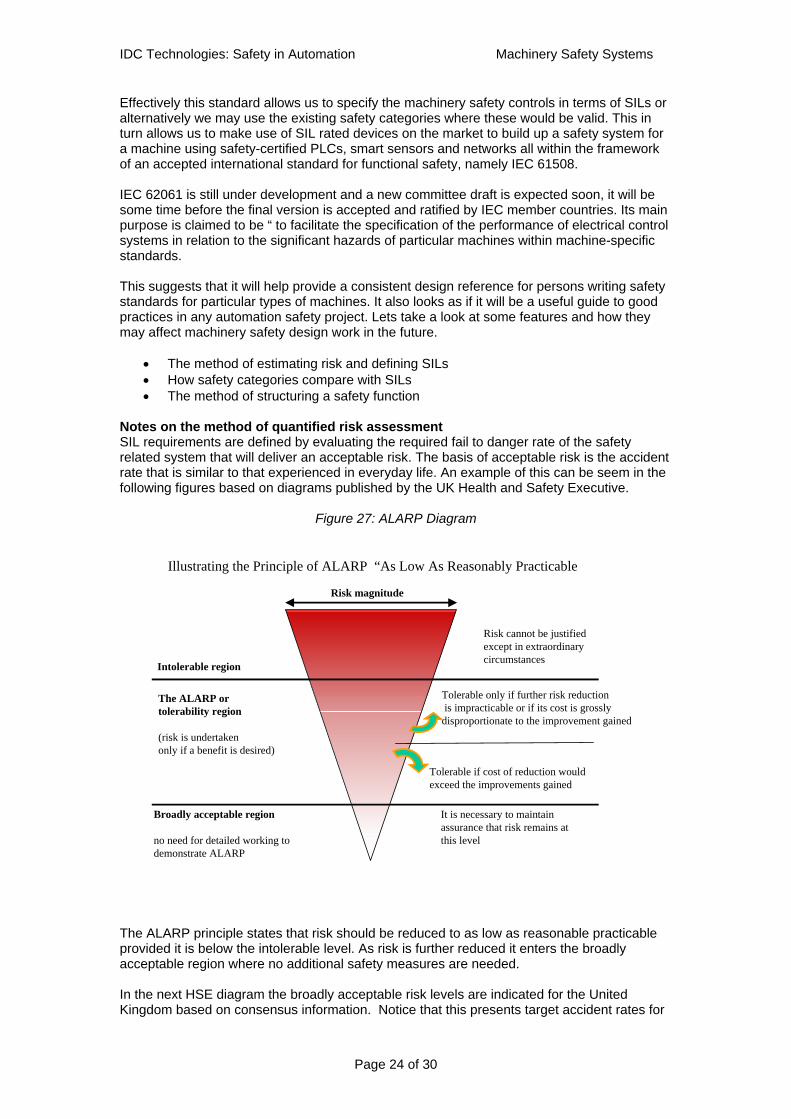
Notes on the method of quantified risk assessment SIL requirements are defined by evaluating the required fail to danger rate of the safety related system that will deliver an acceptable risk. The basis of acceptable risk is the accident rate that is similar to that experienced in everyday life. An example of this can be seem in the following figures based on diagrams published by the UK Health and Safety Executive.
Figure 27: ALARP Diagram
The ALARP principle states that risk should be reduced to as low as reasonable practicable provided it is below the intolerable level. As risk is further reduced it enters the broadly acceptable region where no additional safety measures are needed. In the next HSE diagram the broadly acceptable risk levels are indicated for the United Kingdom based on consensus information. Notice that this presents target accident rates for
Illustrating the Principle of ALARP “As Low As Reasonably Practicable
Intolerable region
Broadly acceptable region
no need for detailed working to demonstrate ALARP
The ALARP or tolerability region
(risk is undertaken only if a benefit is desired)
Risk cannot be justified except in extraordinarycircumstances
Tolerable only if further risk reductionis impracticable or if its cost is grossly
disproportionate to the improvement gained
It is necessary to maintainassurance that risk remains at this level
Tolerable if cost of reduction would exceed the improvements gained
Risk magnitude

IDC Technologies: Safety in Automation Machinery Safety Systems
Page 25 of 30
different classes of consequence. This means for example that if the probability of a fatal accident for an individual is reduced to below 10-6 per year it will be no more risky than everyday life for a member of the public. So we have numerical targets for the risk levels that we would like to achieve. The same principles apply to target rates for accidents with serious consequences and for minor consequences.
Figure 28: ALARP diagrams for classes of consequence
Using quantitative risk targets makes it possible to draw up reliability performance targets for safety related control systems. The draft version of IEC 62061 proposes the following method to arrive at the required SIL rating for a safety function. Step 1: The accident rate is derived by combining the frequency of a person becoming exposed to the danger with the frequency of a dangerous failure of the safety function. The following is a fault tree model of the potential accident situation.
Figure 29
Quantitative risk analysis: fault tree for machinery accident
Hazardous Event
Safety Function Failed to Danger
AND
Accident Frequency = F1 x F2
F1 events/hr F2 = failures/hr
Person in danger zone(Dangerous event)
Frequency of datum event
Pre-condition factors
Human error probability
ANDAND
Risk Criteria Guidelines from HSE
Frequency per year
10-5
10-6
10-7
10-4
10-3
10-2
10-1
Fatal or permanent
serious disability
Irreversible injury
Reversible injury
Intolerable
Alarp
Broadly acceptable

IDC Technologies: Safety in Automation Machinery Safety Systems
Page 26 of 30
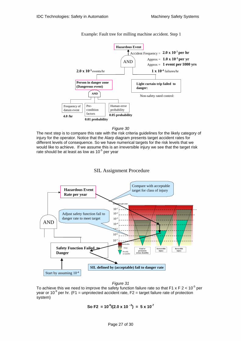
The fault tree model indicates that an accident occurs if a person becomes directly exposed to danger at the same time that the safety function designed to protect against the accident has failed to a dangerous state. As an example: Suppose that an operator has to place a work piece in a multi-function milling machine running an automatic programme.
• The datum event is that he reaches across the machining table to unlock the work piece. Lets suppose this has to be 4 times every hour per 8 hours working shift. The operator is required to stop the machine and allow it time to cease all movement before reaching into the danger zone. An accident occurs if he reaches into the danger zone this before the operating cycle has finished and he gets caught and injured by a moving cutting tool.
• For this event to occur he must make a human error of repetition by forgetting to stop
the machine or by not realizing the machine is moving. The probability of this has been taken to be 0.05.
• Preconditions such as machine defects or misalignment of the work piece modify the
probability of human error. In this example we can take the likelihood as “probable” but not “frequent”. The draft standard suggests a probability factor of 0.01.
The frequency of the datum event is calculated for this machine based on the operator’s the involvement time with the machine. In this case we estimate it to average 4 events per hour of the operator’s time at work. For estimating pre conditions we need to consider what factors would be likely to cause the error. The pre-condition is considered to be part of the sequence of events that leads to the potential accident and it provides a probability factor for the event. The contributing factors will include:
• Human factors such as time pressure to produce more output, ignoring of stated procedures and loss of concentration.
• Environment: High noise levels, poor access to the machine, poor lighting. • Machine condition: Poor maintenance, inadequate or poorly fitted guards. • Machine operation: Inadequate stopping performance, operation in wrong cycle.
This the most difficult aspect of the quantitative risk estimation and it requires that an experienced person should examine the intended use of the machine and review all the factors that may influence the rate at which the operator will make an error. The fault tree model in figure 27 tell us that the event frequency for the operator being in exposed to the accident at any time is 4.0 x 0.01 x 0.05 = 2.0 x 10⁻³ per hr. This predicts an approximate accident rate of 4 events per year (2000 hrs per year) for this worker if no safety devices are fitted. The operator is to be protected by a safety function which in this case is proposed as a light- curtain screen across the approach to the cutting table that will trip the machine to an emergency stop if the infra-red beams are interrupted. For the moment we will assume this function has not been SIL rated but is part of the basic control system for the machine. We will apply an estimated failure rate of 1 x 10⁻⁴ faults per hour as a trial value. Applying this figure to the fault tree delivers an accident rate of 1 x 10 –7 per hr or a risk rate of approximately 1.0 x10 –3 per year for the operator.
IDC Technologies: Safety in Automation Machinery Safety Systems
Page 27 of 30
Figure 30
The next step is to compare this rate with the risk criteria guidelines for the likely category of injury for the operator. Notice that the Alarp diagram presents target accident rates for different levels of consequence. So we have numerical targets for the risk levels that we would like to achieve. If we assume this is an irreversible injury we see that the target risk rate should be at least as low as 10-5 per year
Figure 31
To achieve this we need to improve the safety function failure rate so that F1 x F 2 < 10-5 per year or 10-9 per hr. (F1 = unprotected accident rate, F2 = target failure rate of protection system)
So F2 = 10-9/(2.0 x 10 –3) = 5 x 10⁻⁷
SIL Assignment Procedure
Hazardous EventRate per year
Frequency per year
10-5
10-6
10-7
10-4
10-3
10-2
10-1
Fatal or permanent
serious disability
Irreversible injury
Reversible injury
Intolerable
Alarp
Broadly acceptable
Safety Function Failed to Danger
Adjust safety function fail to danger rate to meet target
Compare with acceptable target for class of injury
AND
SIL defined by (acceptable) fail to danger rateStart by assuming 10-4
Example: Fault tree for milling machine accident. Step 1
Hazardous Event
Light curtain trip failed to danger:
AND
Accident Frequency =
4.0 /hr
Person in danger zone(Dangerous event)
Frequency of datum event
Pre-condition factors
Human error probability
ANDAND
0.01 probability0.05 probability
Non-safety rated control:
1 x 10⁻⁴ failures/hr2.0 x 10-3 events/hr
2.0 x 10⁻⁷ per hr1.0 x 10-3 per yrApprox =1 event per 1000 yrsApprox =

IDC Technologies: Safety in Automation Machinery Safety Systems
Page 28 of 30
Figure 32
The SIL table indicates that this requires a SIL 2 rated safety function.
Figure 33 Conclusion: The quantified risk assessment method illustrated here is mapped out in IEC 62061 with an appendix that is still under development. The standards committee has recognized that fault tree methods require specialized skills and proposed a series of “Fill in the blanks “ forms that would assist users to follow a systematic procedure to arrive at the SIL rating (if any is needed) for each safety function. However, as can be seen from the fault tree example the result of the risk estimation process depends heavily on the estimates of the factors predicting the exposure and error rates of the persons close to the machine. How does this compare with the safety category?
Example: Fault tree for milling machine accident. Step 3
Hazardous Event
AND
Accident Frequency =
4.0 events/hr
Person in danger zone(Dangerous event)
Frequency of datum event
Pre-condition factors
Human error probability
ANDAND
0.01 probability0.05 probability
Safety rated control: SIL 2
5.0 x 10⁻⁷ failures/hr
1 x 10⁻⁹ per hr1 x 10-5 per yrApprox =
Light curtain trip failed to danger:
2.0 x 10⁻³ events/hr
Safety Integrity Safety Integrity levellevel
Continuous Mode of OperationContinuous Mode of Operation(probability of a dangerous failure per hr)(probability of a dangerous failure per hr)
>10>10--88 to < 10to < 10--773 3 >10>10--77 to < 10to < 10--662 2 >10>10--66 to < 10to < 10--551 1
IEC IEC 6206162061 Safety Integrity LevelsSafety Integrity Levelsfor Continuous Mode of Operationfor Continuous Mode of Operation
5 x 10⁻⁷ failures/hrSIL 2

IDC Technologies: Safety in Automation Machinery Safety Systems
Page 29 of 30
If we use the decision chart in EN 954 9 (see figure 21) it looks like we would call for a category 3 safety system. Here we can take note that the standard makes provision for an approximate match between the EN 954 safety categories and the SILs. See the table in figure 34 below with comments.
Figure 34
So in calling for a SIL 2 solution for the milling machine example we would expect to have a Category 3 rated light curtain with a safe failure fraction in the range 60% to 90%. Using the EN954 guidance chart we found the category would probably be 3. No real disagreement here but the benefit of defining the solution as a SIL rating is that all the important features of a SIL 2 safety system are spelt out in the IEC 61508 standard for programmable systems. It tells us how to build a SIL 2 system in hardware and software and we can buy SIL 2 rated equipment certified by a testing /assessment authority. The other advantage of the SIL determination method is that the risk assessment model can be set out with quantified probability values. This allows the circumstances of the safety system to be carefully modeled and recorded for further evaluation or auditing. Conclusion: All of this looks quite daunting for the project engineer faced with an automation task for perhaps integrating several machines into an assembly line. However the process of risk assessment has not been changed by this standard, it remains true to the detailed safety principles set down in EN 292 and the risk assessment principles detailed in E 1050. So there is perhaps no real increase in burden here. The advantages of using SIL ratings for the safety function is that the standards for programmable systems can then be directly applied and the safety system equipment manufacturers will offer products that are compliant with particular SIL ratings based on IEC 61508. It also important to note that it just been announced by the European standards organizations that the EN954 standard is to be replaced by a new standard to be numbered ISO 13849-1. It is beloved that this standard will follow the route of IEC 62061 in specifying risk reduction performance in terms of “performance levels” or PLs in same way as SILs. At this stage it is
Safe failure fraction Hardware fault tolerance
Category to EN 954 Maximum SIL claim
0 B Not valid as a SIL < 60% 0 1 1
> 60% - < 90% 0 2 1 < 60% 1 3 1
> 60% - < 90% 1 3 2 > 60% - < 90% >1 4 3
> 90% 1 4 3
Comparison of Safety Categories and SIL ratings.Comparison of Safety Categories and SIL ratings.((applicable to hardware subsystems only)applicable to hardware subsystems only)
N B : Safe Failure Fraction is ratio of all safe faults + dangerN B : Safe Failure Fraction is ratio of all safe faults + dangerous ous detected faults to all possible faults. Diagnostics are used to detected faults to all possible faults. Diagnostics are used to detect detect dangerous faults.dangerous faults.
IDC Technologies: Safety in Automation Machinery Safety Systems
Page 30 of 30
not clear whether SILs and PLs are effectively the same. (Reference source: PILZ newsletter April 2003). Looking at the present situation we can conclude with following summary points:
• The established methods of defining safety requirements by category remain suitable for simple hardwired safety applications but have become unsuitable for PES applications
• Safety categories do not adequately describe the type of safety system solutions now
available in PES devices. There is risk that many existing machinery builders are not in compliance with good practices for PES based safety solutions.
• Safety-certified PLCs and networks have become established technology for
automation in machinery.
• The lack of a suitable standard has been overcome so far by showing equivalent performance can be obtained by systems compliant with IEC 61508. This has been an inefficient and temporary way to deal with the changing technologies of safety.
• The new sector standard IEC62061 or the planned replacement for EN 954, ISO
13849-1 (Safety of machinery, Safety related parts of control systems, General principles for design), will hopefully assist designers to specify a SIL rating for each safety function in a project. However this will require a cultural shift from qualitative risk assessment to greater use of quantitative risk assessment.
• Using SIL based design methods in the new standards will help to unify the design
practices for machinery safety with those in other industries. The new standards will present internationally accepted practices for ensuring safety in the high performance machines and control system of the future.
References:
1. Siemens Safety Integrated- Application Manual. (www.siemens.de/safety) 2. PILZ: Guide to machinery safety –6th edition 1999 (www.pilz.com) 3. PILZ: Guide to progammable safety systems Volume 2, 1st Edition 4. Guardmaster: product guide and safety navigator 5. IEC 61508-1-7 Functional safety of electrical/electronic/programmable electronic
safety-related systems. International Electrotechnical Commission 3, rue de Varembé1211 GENEVA 20, Switzerland. (www.iec.ch).
6. IEC 61511 parts 1-3: Functional safety: Safety instrumented systems for the process industry sector.
7. CommitteeDraft for IEC 62061: Safety of machinery –Functional safety of electrical, electronic and programmable control systems.version 44/380/CD , 1/05/2002.7
8. IDC Technologies: training workshop manual: Practical safety instrumentation and emergency shutdown systems. Ver 7.0, 2002 (www.idc-online.com)
Revision control: 1st issue. D M Macdonald. 7 April 2003 For questions arising from this paper please e-mail to Dave Macdonald or Steve Mackay at [email protected].