new medium voltage dc railway electrification system · - solid state dc circuit breakers for hvdc...
TRANSCRIPT

1 UIC Workshop "Energy efficient Infrastructures”
New Medium Voltage DC railway electrification system
P. Ladoux : University of Toulouse; H. Caron and C. Courtois : SNCF Réseau and A. Verdicchio PhD student : University of Toulouse / SNCF Réseau
Reference : “New Medium Voltage DC railway electrification system”, A. VERDICCHIO, P. LADOUX, H. CARON, C. COURTOIS IEEE transaction on transportation electrification Vol: 4, Issue 2, June 2018, (p. 591-604)
2 UIC Workshop "Energy efficient Infrastructures”
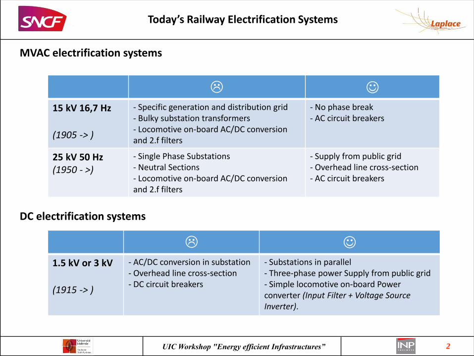
Today’s Railway Electrification Systems
MVAC electrification systems
L J
15 kV 16,7 Hz
(1905 -> )
- Specific generation and distribution grid - Bulky substation transformers - Locomotive on-board AC/DC conversion and 2.f filters
- No phase break - AC circuit breakers
25 kV 50 Hz (1950 - >)
- Single Phase Substations - Neutral Sections - Locomotive on-board AC/DC conversion and 2.f filters
- Supply from public grid - Overhead line cross-section - AC circuit breakers
DC electrification systems
L J
1.5 kV or 3 kV
(1915 -> )
- AC/DC conversion in substation - Overhead line cross-section - DC circuit breakers
- Substations in parallel - Three-phase power Supply from public grid - Simple locomotive on-board Power converter (Input Filter + Voltage Source Inverter).
3 UIC Workshop "Energy efficient Infrastructures”
Why looking to a MVDC Railway Electrification System ?
To mix advantages of the existing electrification systems - Power sharing between Substations - Three-phase power Supply from public grid - Simple locomotive on-board Power converter (Input Filter + Voltage Source Inverter) - Light overhead line and no inductive voltage drop
Power electronics is mature enough - HVDC power converters (up to +/- 800 kV , 3 GW) are operated everywhere in the world. - Solid State DC Circuit Breakers for HVDC grids are tuned. - MV drives for industrial motors (6 KV to 10 kV) are commercially available. - SiC power semi-conductors enable the realization of compact MV traction converters.
A real breakthrough for the future of rail transportation - A solution for countries which do not yet have electrified railway lines - A solution for DC lines renewal (copper savings, energy efficiency increase). - Easier integration of renewable energy sources and storage elements (MVDC smart grid).

4 UIC Workshop "Energy efficient Infrastructures”
Approach to the problem
Considered voltage ranges
Vn (kV) Vmin (kV)
Vmax (kV)
Esub-station (kV)
Esub-station/Vn
1.5
1.0 1.8 1.75 0.85
3
2.0 3.6 3.5 0.85
4.5
3.0 5.4 5.25 0.85
6
4.0 7.2 7.0 0.85
7.5
5.0 9.0 8.75 0.85
9 6.0 10.8 10.5 0.85
10.5 7.0 12.6 12.25 0.85
The same proportionality rule as the European Standard EN 50163 for 1.5 kV DC and 3 kV DC

5 UIC Workshop "Energy efficient Infrastructures”
Approach to the problem
Considered traction circuit
Double track line with a paralleling station at sector mid-point
V p
Substation spacing
Train spacing
Overhead line
Rail
Substation
Paralleling station
6 UIC Workshop "Energy efficient Infrastructures”
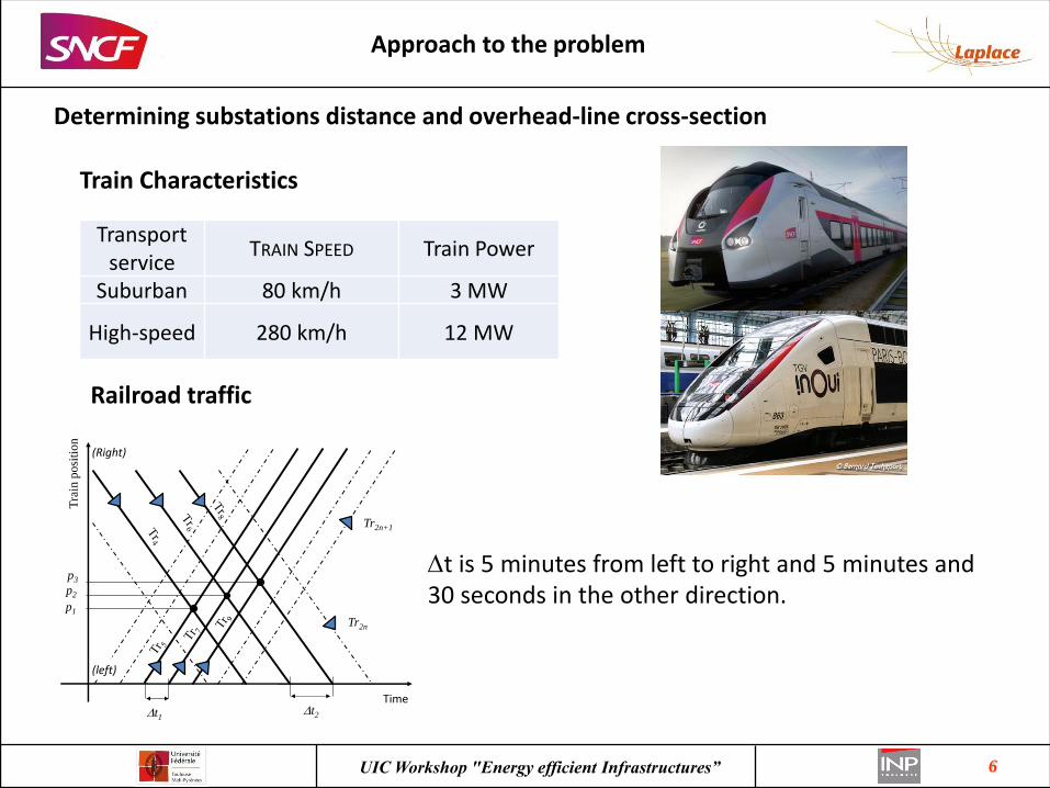
Approach to the problem
Determining substations distance and overhead-line cross-section
Tra
in p
osi
tio
n
Time
p1
p2
p3
Dt1Dt2
Tr2n
Tr2n+1
(left)
(Right)
Railroad traffic
Transport service
TRAIN SPEED Train Power
Suburban 80 km/h 3 MW
High-speed 280 km/h 12 MW
Train Characteristics
Dt is 5 minutes from left to right and 5 minutes and 30 seconds in the other direction.
7 UIC Workshop "Energy efficient Infrastructures”
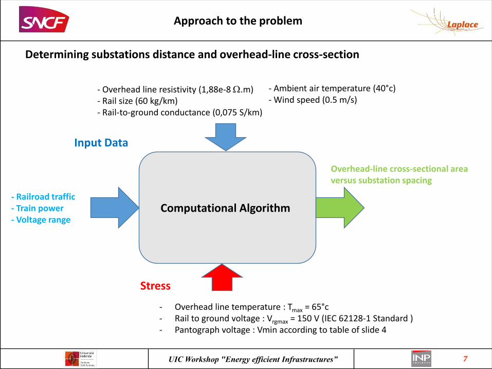
Approach to the problem
Determining substations distance and overhead-line cross-section
Computational Algorithm
Input Data
- Overhead line temperature : Tmax = 65°c - Rail to ground voltage : Vrgmax = 150 V (IEC 62128-1 Standard ) - Pantograph voltage : Vmin according to table of slide 4
- Overhead line resistivity (1,88e-8 W.m) - Rail size (60 kg/km) - Rail-to-ground conductance (0,075 S/km)
Stress
- Ambient air temperature (40°c) - Wind speed (0.5 m/s)
- Railroad traffic - Train power - Voltage range
Overhead-line cross-sectional area versus substation spacing

8 UIC Workshop "Energy efficient Infrastructures”
Computation results
Determining substations distance and overhead-line cross-section
- - - thermal operating limit maximal permitted rail-to-ground voltage
Computation Results

9 UIC Workshop "Energy efficient Infrastructures”
Simulation results
9 kV DC high-speed line – Substation spacing 45 km; Overhead-line cross-section 340 mm2. Train power 12 MW; Train speed 280 km/h
Railroad traffic Overhead-line temperatures calculated close to the substations
Pantograph voltages Currents absorbed by trains
New MVDC Railway Electrification System
10 UIC Workshop "Energy efficient Infrastructures”
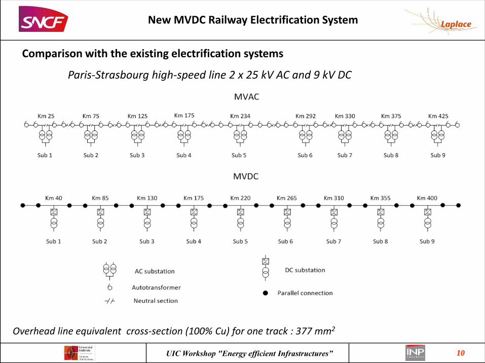
Comparison with the existing electrification systems
New MVDC Railway Electrification System
Paris-Strasbourg high-speed line 2 x 25 kV AC and 9 kV DC
Overhead line equivalent cross-section (100% Cu) for one track : 377 mm2

11 UIC Workshop "Energy efficient Infrastructures”
Comparison with the existing electrification systems
New MVDC Railway Electrification System
Paris-Strasbourg high-speed line with 9 kV DC Electrification system
Simulation results : real railroad traffic between 15:00 and 19:30
Trains from Paris to Strasbourg Trains from Strasbourg to Paris
Energy Efficiency of Traction Circuit (Computation from 16:00 to 18:00)
0,94 for 9 kV DC and 2 x 25 kV AC
12 UIC Workshop "Energy efficient Infrastructures”
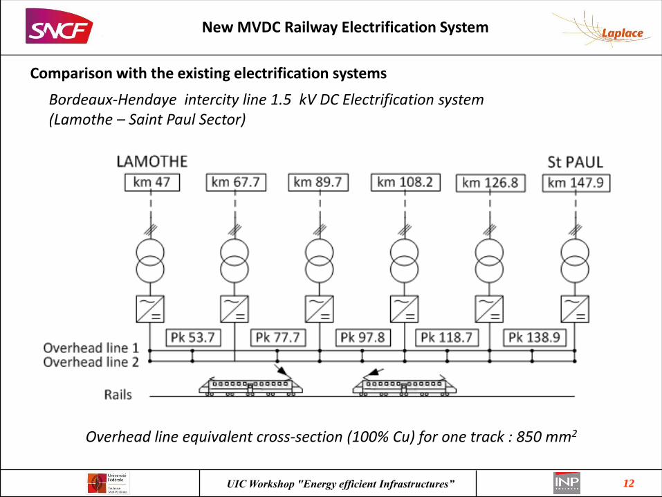
Comparison with the existing electrification systems
New MVDC Railway Electrification System
Bordeaux-Hendaye intercity line 1.5 kV DC Electrification system (Lamothe – Saint Paul Sector)
Overhead line equivalent cross-section (100% Cu) for one track : 850 mm2
13 UIC Workshop "Energy efficient Infrastructures”
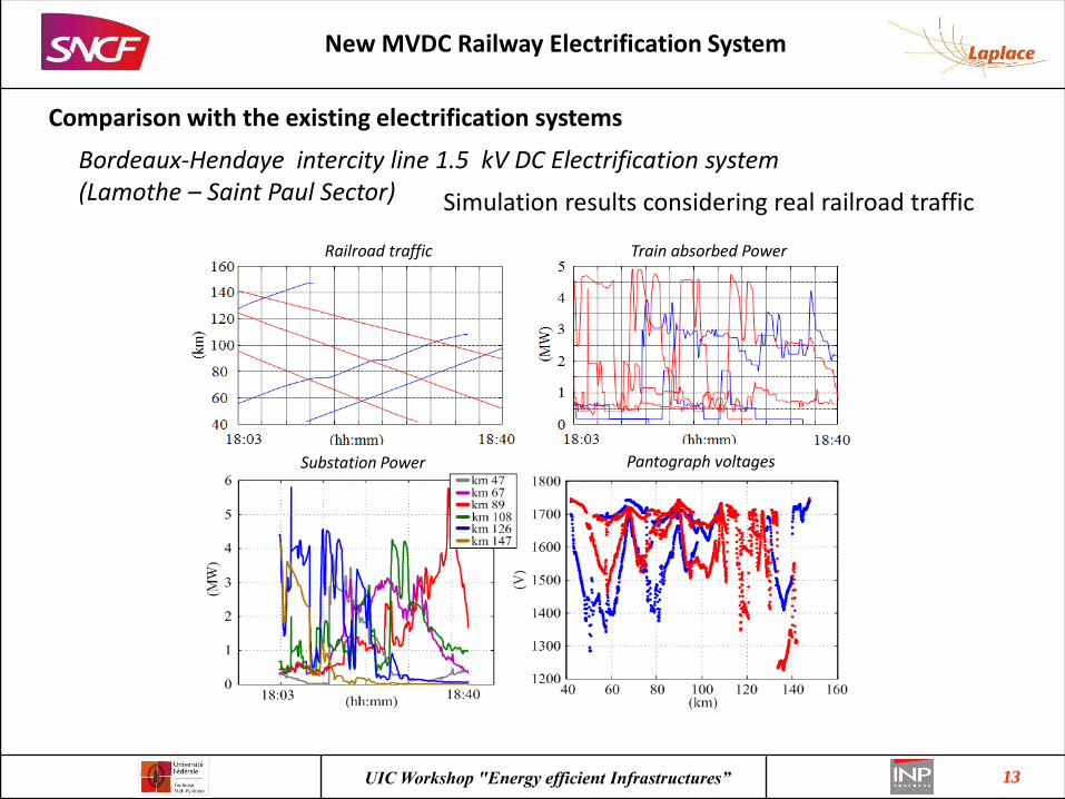
Simulation results considering real railroad traffic
Comparison with the existing electrification systems
New MVDC Railway Electrification System
Bordeaux-Hendaye intercity line 1.5 kV DC Electrification system (Lamothe – Saint Paul Sector)
Railroad traffic
Pantograph voltages
Train absorbed Power
Substation Power
14 UIC Workshop "Energy efficient Infrastructures”
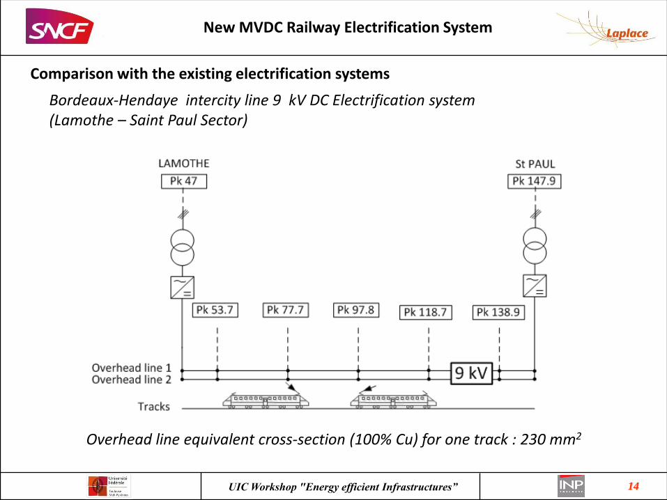
Comparison with the existing electrification systems
New MVDC Railway Electrification System
Bordeaux-Hendaye intercity line 9 kV DC Electrification system (Lamothe – Saint Paul Sector)
Overhead line equivalent cross-section (100% Cu) for one track : 230 mm2

15 UIC Workshop "Energy efficient Infrastructures”
Comparison with the existing electrification systems
New MVDC Railway Electrification System
Bordeaux-Hendaye intercity line 9 kV DC Electrification system (Lamothe – Saint Paul Sector)
Pantograph voltages
Rail to ground voltage (absolute value)
Substation Power
Overhead line temperature
16 UIC Workshop "Energy efficient Infrastructures”
Comparison with the existing electrification systems
New MVDC Railway Electrification System
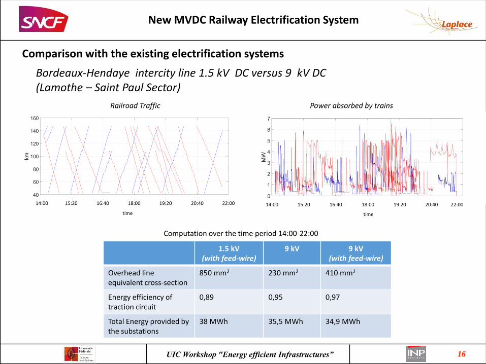
Bordeaux-Hendaye intercity line 1.5 kV DC versus 9 kV DC (Lamothe – Saint Paul Sector)
Computation over the time period 14:00-22:00
Railroad Traffic
time
14:00 15:20 16:40 18:00 19:20 20:40 22:00
Power absorbed by trains
time
14:00 15:20 16:40 18:00 19:20 20:40 22:00
1.5 kV (with feed-wire)
9 kV 9 kV (with feed-wire)
Overhead line equivalent cross-section
850 mm2 230 mm2 410 mm2
Energy efficiency of traction circuit
0,89 0,95 0,97
Total Energy provided by the substations
38 MWh 35,5 MWh 34,9 MWh
17 UIC Workshop "Energy efficient Infrastructures”
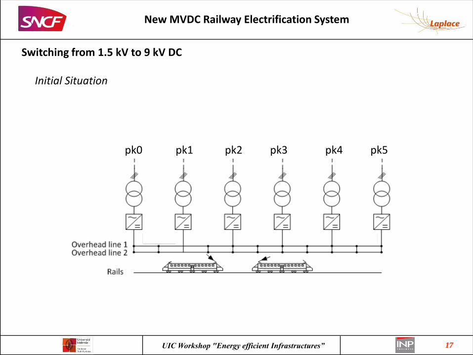
Switching from 1.5 kV to 9 kV DC
New MVDC Railway Electrification System
Initial Situation
pk1 pk2 pk3 pk4 pk5 pk0
18 UIC Workshop "Energy efficient Infrastructures”
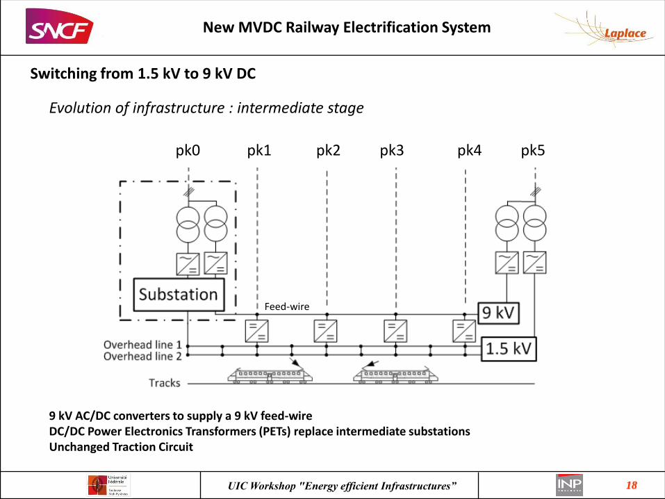
Switching from 1.5 kV to 9 kV DC
New MVDC Railway Electrification System
Evolution of infrastructure : intermediate stage
9 kV AC/DC converters to supply a 9 kV feed-wire DC/DC Power Electronics Transformers (PETs) replace intermediate substations Unchanged Traction Circuit
Feed-wire
pk1 pk2 pk3 pk4 pk5 pk0

19 UIC Workshop "Energy efficient Infrastructures”
Switching from 1.5 kV to 9 kV DC
New MVDC Railway Electrification System
Evolution of infrastructure : Final stage
pk5 pk0
Paralleling station with Hybrid Circuit Breakers are installed along the line

20 UIC Workshop "Energy efficient Infrastructures”
Switching from 1.5 kV to 9 kV DC
New MVDC Railway Electrification System
Evolution of traction units
Intermediate Stage : On Board Power Electronics Transformer
isolated dc-dc
converter
9 kV DC
MFT
Submodule 3
Submodule N
MVin/N
Resonant DAB based on SiC MOSFETs
Three-phase
VSC
1.5 kV DC
Vin
Pantograph
rails
Final Stage : MV traction inverter
4.5 kV
9 kV DC
M
rails
Pantograph
NPC VSI based on 10 kV SiC MOSFETS
3.3 kV SiC MOSFETS are available