new limitation change to - defense technical … · 2. j47-ge-13 engine thrust vs rpm for various...
TRANSCRIPT

UNCLASSIFIED
AD NUMBER
AD095757
NEW LIMITATION CHANGE
TOApproved for public release, distributionunlimited
FROMDistribution authorized to U.S. Gov't.agencies and their contractors;Administrative/Operational Use; Aug 1955;Other requests shall be referred toAeronautical Systems Div.,Wright-Patterson, OH 45433.
AUTHORITY
AFMC ltr, 19 Feb 2002
THIS PAGE IS UNCLASSIFIED

UNCLASSIFIED
AD NUMBER
AD095757
CLASSIFICATION CHANGES
TO
unclassified
FROM
confidential
AUTHORITY
DoDD 5200.10 dtd 26 Jul 1962
THIS PAGE IS UNCLASSIFIED

CO~NFIDE TIAL
~r~drvce~i~n7ifnfornitionjnc
Reproduced byDOCUMENT S.ERVICE CENTER
KNOTT BUILDING, DAYTON, 2, OHIO
This docuttent is the property of the United States Government. It is furnished for the du-ration cit tt.rý cc itract and shall be returned when no longer required, or upon recall by ASTIA
the follow',ig address: Armed Services Technical Information Agency,ij oo urenI. gervice Center, ¬t Building., Dayton 2, Ohio.
NOTrICE: WFIrl GOVERNMENT OR OTHER DRAWINGS, SPECIFICATIONS OR OTHER DATAWR-R\0- D FOR ANY PURPOSE OTHER THAN IN CONNECTION WITH A DEFINITELY RELATEDGOV9RNMZJ ;, PROCUREMENT OPERATION THE U. S. GOVERNMENT THEREBY INCURSNO RESPOIN1318 1T4I NOR ANY OBLIGATONG WHATSOEVER; AND THE FACT THAT THEGOVERNMENT MAY HAVE FORMULATED, FURNISHED, OR IN ANY WAY SUPPLIED THESAID GRAWINGS, SPECIFICATIONS, OR OTHER DATA IS NOT TO BE REGARDED BYIMPLICATION )R OTHERWISE AS IN ANY MANNER LICENSING THE HOLDER OR ANY OTHER[PERSON OR CC RPORATION, OR CONVEYING ANY RIGHTS OR PERMISSION TO MANUFACTURE,USE Oft SELL j•NY PATENTED INVENTION THAT MAY IN ANY WAY BE RELATED THERETO.
~ L inm~~L *1 A

CONFIDENTIAL
WP-TECHNICAL NOTE 55 -298
t.(-" I (UNCLASSIFIED TITLE)
WAR EMERGENCY THRUST AUGMENTATIONFOR THE J47 ENGINE IN THE F- 86 AIRCRAFT
WILLIAM A. DAILEY, Ist Lt, USAF
POWER PLANT LABORATORY
AUGUST 1955
jUN 5 Sll'
WRIGHT AIR DEVELOPMENT CENTER
55WCLPR-10637 - 45
CONFIDENTIAL
AF.wp.-o-31 MA Y 6

NOTICE: THIS DOCUMENT CONTAINS INFORMATION AFFECTING THE
NATIONAL DEFENSE OF THE UNITED STATES WITHIN THE MEANING
OF THE ESPIONAGE LAWS, TITLE 18, U.S.C., SECTIONS 793 and 794.
'THE TRANSMISSION OR THE REVELATION OF ITS CONTENTS IN
ANY MANNER TO AN UNAUTHORIZED PERSON IS PROHIBITED BY LAW.
. -

CONFIDENTIAL
WADC TECHNICAL NOTE 55- 298
(UNCLASSI FIED TITLE)
WAR EMERGENCY THRUST AUGMENTATIONFOR THE J47 ENGINE IN THE F.-86 AIRCRAFT
William A. Dailey, .1st Lt, USAF
Power Plaut Laboratory
A ugust 1955
Project No. ,T - 11 - P - 206A - 16
Wright Air Development CenterAir Research and Development Command
United States Air ForceWright-Patterson Air Force Base, Ohio IJUN 1 5 1956
CONFIDENTIAL

CONFIDENTIAL
FOREWORD
This document was prepared to serve as the finalreport of Power Plant Laboratory Project T-11-P-206A-16,(formerly S506-224J) entitled (Unclassified) "War Emer-gency Thrust Augmentation for the J47 Turbojet EngineInstalled in the F-86 Aircraft". The project was adminis-tered by the Rotating Engine Branch, Power Plant Laboratory,Wright Air Development Center.
Acknowledgment for their work on the project is givento the following: F-86 Weapon System Project Office,Wright Air Development Center; Air Force Flight Test Center,Edwards Air Force Base; NACA Lewis Flight PropulsionLaboratory; General Electric Company; and North AmericanAviation Inc.
This document, excepting the title and Sections I andII, is classified CONFIDENTIAL because of the nature of,and potential future military application of the work re-ported on; classification is made in accordance with AirForce Regulation 205-1, paragraph 24a, dated 15 December1953.
WADC TN 55-298
CONFIDENTIAL 5 -10637
CONFIDENTIAL
ABSTRACT
Augmentating the thrust of the J47 engine in the F-86aircraft was the principal objective of the program hereinreported upon. The work covered a period of approximatelytwo and one-half years and was conducted primarily by theGeneral Electric Company and North American Aviation, Inc.under Air Force contract. Work was also accomplished onthe project by the Wright Air Development Center, the AirForce Flight Test Center, and the Lewis Flight PropulsionLaboratory. All known schemes that could possibly augmentthe thrust of a turbojet engine were considered and over-speed, overtemperature, liquid nitrogen injection, water-alcohol injection, and pre-turbine fuel injection werebrought under development. With the exception of overspeedand liquid nitrogen injection, the above systems weretested in flight and demonstrated that they could provideincreased thrust for the J47 engine thereby substantiallyincreasing the performance of the F-86 aircraft. Of thethree augmentation systems flight tested, two drasticallyreduced the life of the engine and the third, water-alcoholinjection, although not having such a severe effect on en-gine life was not suited for installation in the F-86 air-craft. Thus, under the circumstances, adaptation of anythrust augmentation system to the J47 engine in the F-86aircraft for Korean operational use was deemed impractical.
PUBLICATION REVIEW
This report has been reviewed and is approved.
FOR THE COMMANDER:
Colonel, UTSAFChief, Power Plant LaboratoryDirectorate of Laboratories
WADC TN 55-298 iii
55MCLPR-310637CONFIDENTIAL

CONFIDENTIAL
TABLE OF CONTENTS
Section I Overspeed 1
A. General-Testing-Results 1
Section II Overtemperature 3
A. General 3B. Testing 4C. Results 6
Section III Liquid Nitrogen Injection 13
A. General 13B. Testing 14C. Results 17
Section IV Water-Alcohol Injection 21
A. General 21B. Testing 22C. Results 27
Section V Pre-Turbine Injection 33
A. General 33B. Testing 34C. Results 41
Section VI General Conclusions 49
References 52
Appendix 54
WADC TN 55-298 iv
C I T

CONFIDENTIAL
LIST OF ILLUSTRATIONS
Figure Page
1. Project's Significant Events and Dates x
2. J47-GE-13 Engine Thrust Vs RPM For VariousTail-Pipe Area Settings 2
3. J47-GE-13 Engine Compressor EfficiencyDrop-Off With Increased RPM 2
4. F-86L Tail-Pipe Restrictor Segments UtilizedIn the J47-GE-13 Engine Overtemperature Tests 5
5. Auxiliary Throttle Stop Installed On the ThrottleQuadrant In the Cockpit Of the F-86E AircraftDuring the J47-GE-13 Engine OvertemperatureTests 5
6. Overtemperature Test Rate of Climb Data 7
7. Overtemperature Test Time to Climb Data 7
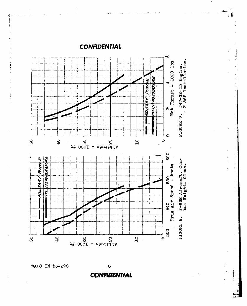
8. Overtemperature Test Level Flight TrueAir Speed Data 8
9. Overtemperature Test Engine Net Thrust Data 8
10. Overtemperature Test Specific Air Range Data 10
11. Overtemperature Test Engine Gross Thrust Data 10
12. Schematic Diagram Of the Liquid Nitrogen TestSet Up Utilizing the J47-GE-15 Engine 16
13. Liquid Nitrogen Injection Test Percent Augmen-tation Vs Injection Flow Rate 18
14. Liquid Nitrogen Injection Test Inlet Air FlowTemperature Decrease Vs Injection Flow Rate. 18
WADC TN 55-298 v
"CONFIDENTIAL
CONFIDENTIAL
15. Schematic Diagram Of the J47-GE-27 EngineWater-Alcohol Injection System Installed Inthe F-86F Aircraft 23
16. J47-GE-27 Engine Water-Alcohol InjectionControl Panel On the Left Forward ConsoleIn the Cockpit of the F-86F Aircraft 25
17. F-86F Tail-Pipe Tab Assembly Utilized Inthe J47-GE-27 Engine Water-Alcohol InjectionTesting 25
18. Water-Alcohol Injection Test Rate Of ClimbData 28
19. Water-Alcohol Injection Test Time To ClimbData 28
20. Water-Alcohol Injection Test Level FlightTrue Air Speed Data 30
21. Water-Alcohol Injection Test Engine NetThrust Data 30
22. Water-Alcohol Injection Test AircraftAcceleration Data 31
23. Water-Alcohol Injection Test InjectionFlow Rate Data 31
24. Schematic Diagram Of the J47-GE-27 Pre-Turbine Fuel Injection System InstallationIn the F-86F Aircraft 36
S25. F-86F Tail-Pipe Variable Area NozzleUtilized In the J47-GE-27 Engine'Pre-Turbine Fuel Injection Tests 39
26. J47-GE-27 Engine Pre-Turbine Fuel. Injec-tion Control Cockpit Presentation In theF-86F Aircraft 39
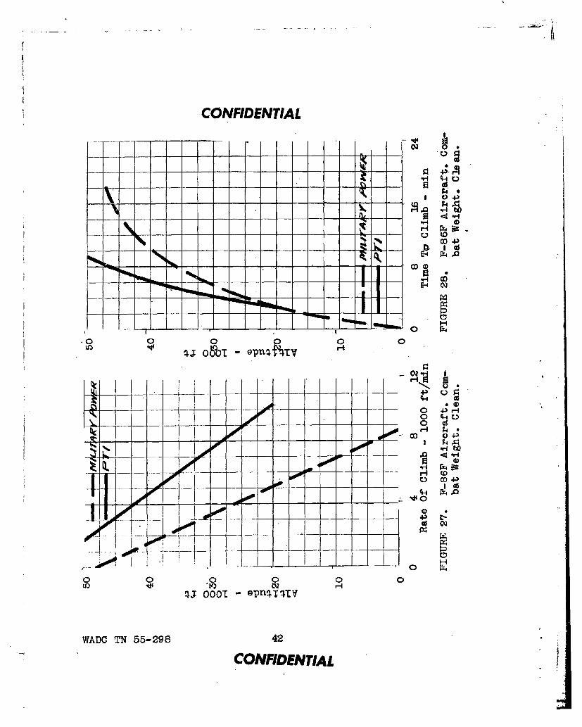
27. Pre-Turbine Fuel Injection Test Rate OfClimb Data 42
WADC TN 55-298 vi
CONFIDENTIAL

CONFIDENTIAL
28. Pre-Turbine Fuel Injection Test Time To ClimbData 42
29. Pre-Turbine Fuel Injection Test Level FlightTrue Air Speed Data 43
30. Pre-Turbine Fuel Injection Test Engine NetThrust Data 43
31. Pre-Turbine Fuel Injection Test AircraftAcceleration Time Data 44
32. Pre-Turbine Fuel Injection Test SpecificFuel Cornsumnpt•.on Dai,. 44,4
33. Pre-Turbine Fuel Injection Test AircraftLoad Factor Ddta 46
34. Pre-Turbine Fuel Injection Test Radius Of
Turn Data 46
35. MiG-15 Rate Of Climb Data 54
36. MIG-15 Time To Climb Data 54
WADC TN 55-298 vii
CONFDENTIAL
CONFIDENTIAL
INTRODUCTI ON
Encounters against the enemy MiG-15 aircraft in Koreadictated that steps be taken to improve the performance ofthe F-86 aircraft. Combat experience demonstrated the in-feriority of the combat and service ceilings of the F-86 air-craft and it was evident that the aircraft's climb perform-An!e was in need of the most improvement. Although the F-86aircraft had higher level flight and dive speeds than theMiG-15 aircraft, the latters ability to accelerate morerapidly to its maximum speed in part made up for its some-what lower maximum attainable speed. It was directed thatthe greatest effort be exerted on measures to improve thecombat capability of the F-86 aircraft with regard to theabove mentioned aircraft performance variables. The pro-duct of these measures was to be something that could beplaced in operational combat use at the earliest possibledate; however, work was to be continued to provide further
Simprovements as soon as they could be made available tosupplant or supplement initial expediencies adopted as emer-gency solutions. The understanding was that measureswhich promised significant performance gains would not berejected on the grounds that engine life would be reducedunless the reduction in life imposed an unsupportable bur-den on supply and maintenance.
The deficiencies of the F-86 aircraft when compared tothe MiG-15 aircraft, as outlined above, were indicative ofone factor which needed improvement-thrust loading. Inorder to make the thrust loading of the F-86 aircraft morenearly equal to that MiG-15 aircraft, an improvement of suchin the order of 50% would have been necessary. The problemwas attacked by attempting to increase the thrust of the F-86aircraft and reduce the aircraft's weight. All the knownmethods of augmenting the thrust of a turbojet engine wereconsidered and many were actually brought under developmentfor the J47 engine, the purpose being to improve the perform-ance of the F-86 aircraft. This report will present and re-view the various technical aspects of the above cited problem.which concern the J47 engine.
Because of the varied and extensive nature of the pro-gram concerning the efforts to augment the thrust of the
WADC TN 55-298 viii
CONFIDENTIAL

CONFIDENTIAL
J47 engine, the work reported upon herein is presentedchronologically rather than in any order pertaining to therelative importance of the various phases of the workaccomplished or the benefits derived from such work. Asthe object of the entire project was to meet an emergency,where timing was necessarily important, pertinent datawith regard to this are presented in Figure 1 for earlyreference. Other steps taken to improve the performanceof the F-86 aircraft, which were not directly related tothe J47 engine, such as rocket boost, aerodynamic improve-ments, weight reductions, etc. are reviewed in numerousother USAF and contractors' documents and will not be sub-jects of this report.
WADC TN 55-298 ix
CONFIDENTIAL

CONFIDENTIAL
._
.o i 0
_~ W~
I Is I • &' Z,
_ I. -_ - -,- -------.
IJU
j, g •
1E1z
'WADC TN 55-296
CONFIDENTIAL

CONFIDENTIAL
SECTION I
OVERSPEED
A. General - Testing - Results
Operating at a higher rotor speed was considered as ameans of increasing the thrust of the J47-GE-13 engine; itwas originally thought that an increase in thrust could beobtained by increasing the air mass flow through the en-gine. When the exhaust nozzle area was not enlarged forsuch operation, an overtemperature condition existed. How-ever, it was soon found that when the exhaust nozzle aroawas so enlarged to maintain the limiting exhaust gas tem-perature, a decrease in thrust, rather than an increaseoccurred. Figure 2 illustrates how the thrust tapers offif the exhaust gas temperature is maintained constant byincreasing the exhaust nozzle area for rotor speeds great-er than 7950 rpm (100%). This condition was due to thecomparatively large decrease in the pressure ratio acrossthe nozzle relative to the increase in the air mass flowthrough the engine. Overspeed operation in itself con-tributed nothing to any additional thrust output when suchoperation was combined with overtemperature due to fall-off in compressor efficiency at the higher values of rpm;Figure 3 illustrates this fall-off in compressor effi-ciency. Should overspeed operation of the engine haveresulted in an increase in thrust, it is doubtful if suchoperation could have been approved for any extensive ser-vice use because of the relatively large increase in cen-trifugal stresses which accompained overspeed. Thesestresses increased approximately 8% when the engine wasoversped by 4%.
WAPO TN 55-298 1 551'ICLPR-10637
CONFIDENTIAL
|I

CONFIDENTIAL
o o14 ILI
100o 00
0 0H00' 00
0~ 0
00
C 00L - c- I .-0 c0
cc co
N 0z-~~ -.- H'
r~ C)
0 t- ýT_ 0 00
771 ) iio 147 vsqT - 1.sflaTU asoJa p~eqbijaaD
WADO TN 55-298
CONFIDENTIAL

CONFIDENTIAL
SECTION II
OVERTEMPERATURE
A. General
Previous experience had demonstrated that any thrustincrease which was derived during the engine overspeedtesting was solely due to overtemperature. Overtemperatureoperation, without overspeed, was then considered as &means of increasing the thrust of the J47-GE-13 engine.Although it was known that overtemperature operation wouldprovide a substantial amount of augmentation, dependentupon the degree of overtemperature, there were many prob-lems which had to be resolved before such operation couldbe approved for use in the field. The most difficult ofthese problems was that of determining a life for the en-gine parts that had been subjected to such overtemperature.It was known from past experience that realistic enginepartst life figures could only be obtained through serviceuse or a long endurance testing program. Possible troubleareas which needed investigation were as follows: ade-quacy of aircraft cooling in parts adjacent to the engine,
-ability of the airframe structure to take the additionalloading and temperatures, and the determining of accuratemeans of setting the rpm and exhaust nozzle area of theengine on the ground to give the desired conditions ataltitude. Attention needed also to be given toward re-solving the problems associated with the use of a small-er area exhaust nozzle with regard to engine control opera-tion, engine acceleration, engine stalls, flame-outs, andstarting.
Since it was not possible to enter into an endurancetype of test program to gather engine parts' life data, itwas decided to determine aircraft performance utilizingovertemperature operation of the engine and to gather asmuch other information as could be had, coincident withsuch performance testing, that might allow a reasonableassessment to be made about the degree of maintenance andlogistic support which would be necessary to allow tacticaluse of engine overtemperature operation.
WADC TN 55-298 3
CONFIDENTIAL

CONFIDENTIAL
B. Testing
Only a small expenditure of work was necessary to allowovertemperature operation and that consisted of placingrestrictor segments in the tail-pipe to decrease the ex-haust nozzle area. Figure 4 illustrates the restrictorsegments placed in the tail-pipe of the J47-GE-13 enginein the F-86E test aircraft. In addition, an auxilial'y stopwas placed on the throttle quadrant in the cockpit. Theauxiliary stop was installed on the throttle quadrant sothat the engine might not be continually operated at anovertemperature condition. The auxiliary stop was set ata position which limited the rpm of the engine to a valuesuch that 100% thrust was obtained at 100% exhaust gastemperature but at lower engine rpm than 100%. The auxil-iary stop was designed so that the throttle could be pushedoutboard and forward to the original full throttle positionthus giving additional thrust resulting from overtempera-ture operation. Figure 5 illustrates the auxiliary stopinstalled on the throttle quadrant in the cockpit of theF-86E test aircraft. Such a system allowed normal opera-tion up to the auxiliary stop and in addition allowed thepilot to obtain additional thrust by advancing the throttlepast the auxiliary stop. Since the rpm was also increasedwhen the throttle was advanced past the auxiliary stop,the air mass flow through the engine was increased slightly.
Approximately 99% thrust was available with the throt-tle at the auxiliary-stop provided 100% exhaust gas tem-perature was maintained at that setting. Not only was 99%thrust available at 93% rpm, but due also to the engine'scomponent characteristics, the full thrust normally avail-able was obtained between 96% and 100% rpm at 100% exhaustgas temperature with due allowances being made for changesaway from standard ambient conditions. Static and flighttesting was accomplished with the auxiliary stop set at7400 rpm (93%) and the exhaust nozzle area so reduced toproduce 12750F(100%) exhaust gas temperature at that en-gine rpm. With such an arrangement, an exhaust gas tem-perature of 1500OF (118%) was produced at 7950 rpm (100%).A timer was installed so that the duration of operationabove 93% rpm could be determined. Flight operation above93% rpm was for the most part limited to one minute cyclesat the overtemperature setting in order to obtain maximum
WADC TN 55-298 4
CONFIDENTIAL

CONFIDENTIAL
FIGURE 4. F-86E Tail-Pipe Restrictor SegmentsUtilized In The J47-GE-13 EngineOvertemperature Tests.
PIGURE 5. Auxiliary Throttle Stop Installed, On TheThrottle Quadrant In The Cockpit Of TheF-86E Aircraft During The J47-GE-13 EngineOvertemperature Tests
WADC TN 55-298 5
.9 CONFIDENTIAL

V
CONFIDENTIAL
life of the turbine buckets. Continuous and cyclic ovArtem-perature operation tests were conducted both on the groundand in flight. Throughout the testing, inspections weremade in an attempt to correlate parts' life deteriorationwith overtemperature operation. A. full metallurgical in-vestigation of all parts subjected to overtemperature wasmade upon completion of the testing.
Two other tests were run in conjunction with the over-temperature flight testing. One such test was the placingof a by-pass needle valve between the large and small slotfuel manifolds to prevent exhaust gas temperature drop-offin climbs and the other was the placing of a 30 psi restric-tor valve in the emergency fuel system side of the doublecheck valve so as to give better temperature regulationwhile climbing. Both of these additional tests were con-ducted with the purpose of alleviating problems which hadbeen experienced in the field.
-C. Results
Figures 6 through 11 are plots of pertinent perform-ance data gathered during the testing phase of an P-86Eaircraft with a J47-GE-13 engine utilizing overtemperatureas a means of thrust augmentation. Data for a standardunaugmented J47-GE-13 engine and F-86E aircraft are sup-plied for comparative purposes.
From Figure 6 it can be seen that the rate-of-climbof the F-86E aircraft wps increased by 1800 ft/min at alti-tudes between 30,000 feet and 45,000 feet when utilizingovertemperature operation of the engine; thus the rate-of-climb was nearly doubled at an altitude of 35,000 feet andnearly tripled at an altitude of 40,000 feet. At an alti-tude of 45,000 feet the rate-of-climb with overtemperatureoperation was four times as great as the rate-of-climb atmilitary power. The time to climb from an altitude of30,000 feet to an altitude of 45,000 feet wasnaeduced byapproximately 8 minutes utilizing overtemperature opera-tion of the engine as can be seen from Figure 7. Figure 8shows a steady incremental increase in maximum level flighttrue air speed of about 10 knots at an altitude of 15,000feet to 15 knots at an altitude of 45,000 feet utilizingovertemperature operation as compared to operation at mili-
WADC TN 55-298 6
CONFIDENTIAL* r

CONFIDENTIAL
J ~0 i
E-4
0.
000"0w
43H
-~~ ~ 4 4-- - - -~;:
I 0o
or-t - p4V
WADO TN 55-298 7
CQNýfIDETIA
CONFIDENTIAL
.--- --v..~ -.--- 0 i4
r- c
I ~00 0- 0 0 0 J
tIr N 0 er
V) 10~~~~. UQT -~~T E
~0
co I c-- -q 0
00 4) IV
doo
0 .CD 4.)
0
00r0 0 Col H .
WADC TN 55-298 8
CONID-ENTIAL
CONFIDENTIAL
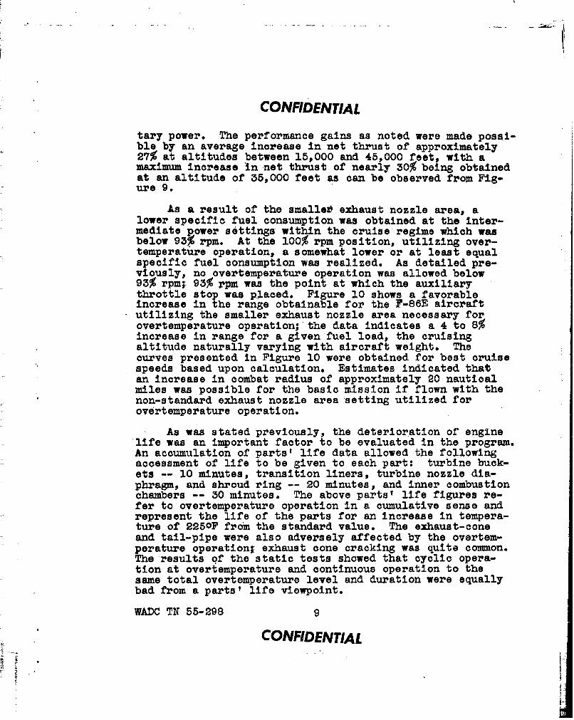
tary power. The performance gains as noted were made possi-ble by an average increase in net thrust of approximately27% at altitudes between 15,000 and 45,000 feet, with amaximum increase in net thrust of nearly 30% being obtainedat an altitude of 35,000 feet as can be observed from Fig-ure 9.
As a result of the smallet exhaust nozzle area, alower specific fuel consumption was obtained at the inter-mediate power settings within the cruise regime which wasbelow 93% rpm. At the 100% rpm position, utilizing over-temperature operation, a somewhat lower or at least equalspecific fuel consumption was realized. As detailed pre-viously, no overtemperature operation was allowed below93% rpm; 93% rpm was the point at which the auxiliarythrottle stop was placed. Figure 10 shows a favorableincrease in the range obtainable for the F-86E aircraftutilizing the smaller exhaust nozzle area necessary forovertemperature operation; the data indicates a 4 to 8%increase in range for a given fuel load, the cruisingaltitude naturally varying with aircraft weight. Thecurves presented in Figure 10 were obtained for best cruisespeeds based upon calculation. Estimates indicated thatan increase in combat radius of approximately 20 nauticalmiles was possible for the basic mission if flown with thenon-standard exhaust nozzle area setting utilized forovertemperature operation.
As was stated previously, the deterioration of enginelife was an important factor to be evaluated in the program.An accumulation of parts' life data allowed the followingaccessment of life to be given to each part: turbine buck-ets -- 10 minutes, transition liners, turbine nozzle dia-phragm, and shroud ring -- 20 minutes, and inner combustionchambers -- 30 minutes. The above parts' life figures re-fer to overtemperature operation in a cumulative sense andrepresent the life of the parts for an increase in tempera-ture of 225oF from the standard value. The exhaust-coneand tail-pipe were also adversely affected by the overtem-perature operation- exhaust cone cracking was quite common.The results of the static tests showed that cyclic opera-tion at overtemperature and continuous operation to thesame total overtemperature level and duration were equallybad from a parts' life viewpoint.
WADC TN 55-298 9
CONFIDENTIAL

CONFIDENTIAL
1j7 .% 0
K -I-
0'2sqT 0001 o-n Sft sooZjo po~oejjoo
to H 0
too
cQ. 000 -oP
,"WADC TN 55-298 10
CONFIDENTIAL
CONFIDENTIAL
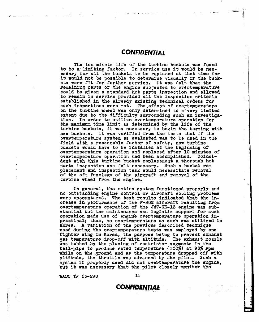
The ten minute life of the turbine buckets was foundto be a-limiting factor. In service use it would be nec-essary for all the buckets to be replaced at that time forit would not be possible to determine visually If the buck-ets were fit for further service. It was felt that theremaining parts of the engine subjected to overtemperaturecould be given a standard hot parts inspection and allowedto remain in service provided all the inspection criteriaestablished in the already existing technical orders forsuch inspections were met. The.effect of overtemperatureon the turbine wheel was only determined to avery limitedextent due to the difficulty surrounding such an investiga-tion. In order to utilize overtemperature operation forthe maximum time limit as determined by the life of theturbine buckets, it was necessary to begin the testing withnew buckets. It was verified from the tests that if theovertemperature system as evaluated was to be used in thefield with a reasonable factor of safety, new turbinebuckets would have to be installed at the beginning ofovertemperature operation and replaced after 10 minutes ofovertemperature operation had been accomplished. Coinci-dent with this turbine bucket replacement a thorough hotparts inspection was felt necessary. Such a bucket re-placement and inspection task would necessitate removalof the aft fuselage of the aircraft and removal of theturbine wheelfrom the engine.
In general, the entire system functioned properly andno outstanding engine control or aircraft cooling problemswere encountered. The test results indicated that the in-crease in performance of the F-86E aircraft resulting fromovertemperature operation of the J47-GE-13 engine was sub-stantial but the maintendnce and logistic support for suchoperation made use of engine overtemperature operation im-practical; thus, no overtemperature as such was utilized inKorea. A variation of the previous described techniqueused during the overtemperature tests was employed by one-fighter wing in Korea, the purpose being to prevent exhaustgas temperature drop-off with altitude. The exhaust nozzlewas tabbed by the placing of restrictor segments in thetail-pipe to produce rated temperature (100%) at 96% rpmwhile on the ground and as the temperature dropped off withaltitude, the throttle was advanced by the pilot. Such asystem if properly used did not overtemperature the engine,but it was necessary that the pilot closely monitor the
WADC TN 55-298 11
CONFIDENTIAL

;I'
CONFIDENTIAL
exhaust gas temperature. The by-pass needle valve betweenthe large and small slot fuel manifolds, which was evalu-ated during a portion of the overtemperature testing, wasalso used in Korea by another fighter wing to accomplishthe same task of reducing exhaust gas temperature drop-offwith altitude. Reduction in the temperature drop-off madepossible the realization of more nearly the full availablethrust at altitude and provided the limiting temperaturewas not exceeded, there would be no reduction in parts'life. As was previously stated, no loss in engine thrustoccurred at the slightly reduced rpm, which was used fortake-off and operation at the lower altitudes,provided100% exhaust gas temperature was maintained.
WADO TN 55-298 32
CONFIDENTIAL"-I

CONFIDENTIAL
SECTION III
LIQUID NITROGEN INJECTION
A. General
One method of thrust augmentation for the J47 enginethat appeared promising on the basis of analytical workconducted was that of liquid refrigerant injection intothe compressor inlet. Such injection artifically cooledthe entering air thereby resulting in a greater air massflow through the engine and hence increased thrust. Thelower temperature of the air flowing through the compres-sor increased the compressor pressure ratio by increasingthe compressor Mach Number and also increased the differ-ence between the temperature at which the work of compres-sion was added to and taken from the working fluid in theengine. Liquid nitrogen and liquid oxygen were the refrig-erants given the most consideration in the studies. It wasconcluded from a theoretical examination that for the sameweight flows of refrigerant injection, liquid nitrogen andliquid oxygen would give approximately the same thrust aug-mentation providing the combustion process was not serious-ly disturbed by the injection of either refrigerant. Li-quid oxygen is however more dense than liquid nitrogen and
p has the advantage of requiring a 14% smaller, storage tankfor the same weight. The use of liquid oxygen was laterruled out because it is dangerous from a handling point ofview; it may explode spontaneously when brought in contactwith grease or oil. Experience had also shown that leak-ages in installations utilizing liquid oxygen do occur andthat the fire hazard is considerable; nitrogen on the otherhand is inert and does not burn or explode.
Hydrogen peroxide, liquid ammonia, methyl chloride, and
liquid air were also considered for possible use but sooneliminated from further consideration. Hydrogen peroxidewas disqualified as a satisfactory coolant at the compara-tively low operating temperatures since its boiling tem-perature is relatively high. Hydrogen peroxide also pre-sented a distinct problem for it is spontaneously combus-tible at temperatures approximating the compressor dis-charge temperature of the J47 engine. Liquid ammonia,
WADC TN 55-298 13
CONFIDENTIAL
ii
CONFIDENTIAL
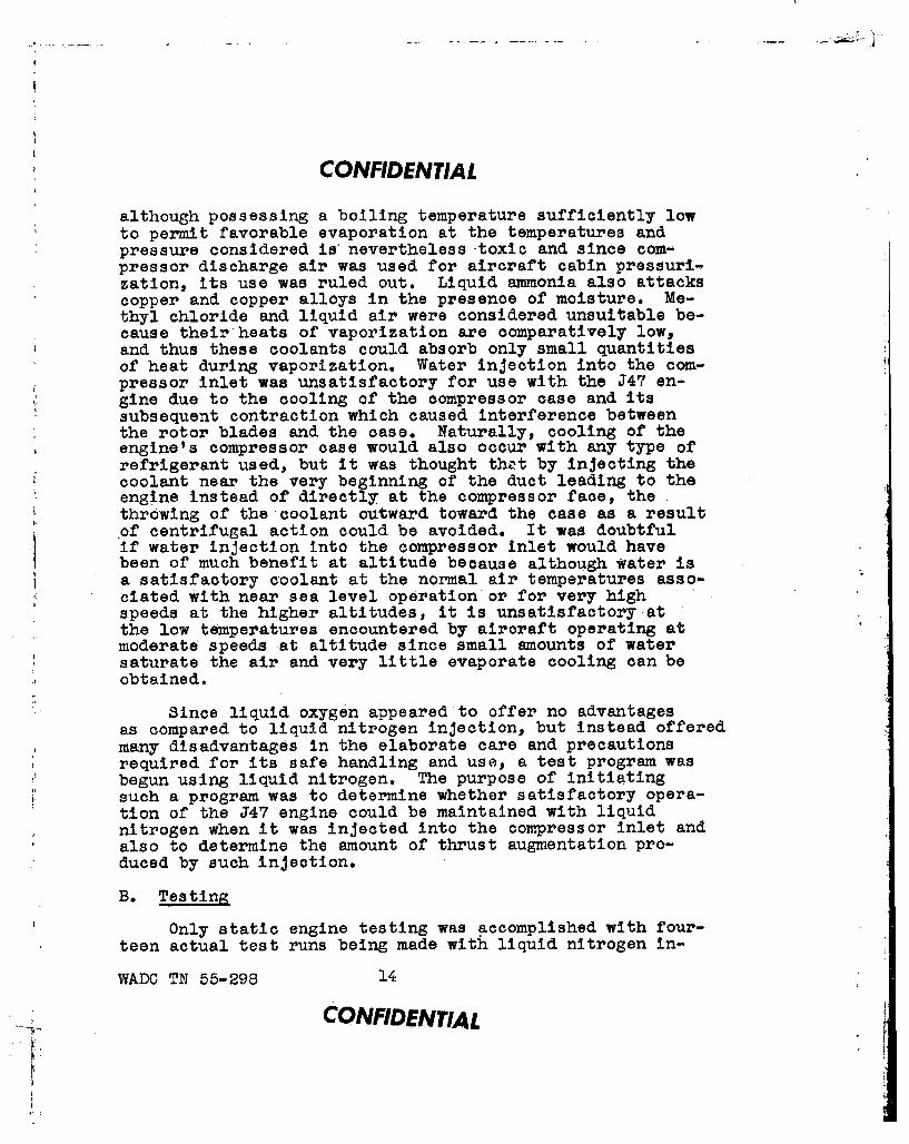
although possessing a boiling temperature sufficiently lowto permit favorable evaporation at the temperatures andpressure considered is' nevertheless toxic and since com-pressor discharge air was used for aircraft cabin pressuri-zation, its use was ruled out. Liquid ammonia also attackscopper and copper alloys in the presence of moisture. Me-thyl chloride and liquid air were considered unsuitable be-cause their heats of vaporization are comparatively low,and thus these coolants could absorb only small quantitiesof heat during vaporization. Water injection into the com-pressor inlet was unsatisfactory for use with the J47 en-gine due to the cooling of the compressor case and itssubsequent contraction which caused interference betweenthe rotor blades and the case. Naturally, cooling of theengine's compressor case would also occur with any type ofrefrigerant used, but it was thought that by injecting thecoolant near the very beginning of the duct leading to theengine instead of directly at the compressor face, thethrowing of the coolant outward toward the case as a result*of centrifugal action could be avoided. It was doubtfulif water injection into the compressor inlet would havebeen of much benefit at altitude because although water isa satisfactory coolant at the normal air temperatures asso-ciated with near sea level operation or for very highspeeds at the higher altitudes, it is unsatisfactory atthe low temperatures encountered by aircraft operating atmoderate speeds at altitude since small amounts of watersaturate the air and very little evaporate cooling can beobtained.
Since liquid oxygen appeared to offer no advantagesas compared to liquid nitrogen injection, but instead offeredmany disadvantages in the elaborate care and precautionsrequired for its safe handling and use, a test program wasbegun using liquid nitrogen. The purpose of initiatingsuch a program was to determine whether satisfactory opera-tion of the J47 engine could be maintained with liquidnitrogen when it was injected into the compressor inlet andalso to determine the amount of thrust augmentation pro-duced by such injection.
B. Testing
Only static engine testing was accomplished with four-teen actual test runs being made with liquid nitrogen in-
WADC TN 55-298 14
CONFIDENTIAL
t
CONFIDENTIAL
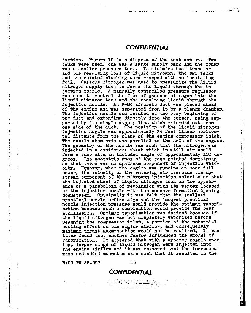
jection. Figure 12 is a diagram of the test set up. Twotanks were used, one was a large supply tank and the otherwas a smaller pressure tank. To minimize heat transferand the resulting loss of liquid nitrogen, the two tanksand the related plumbing were wrapped with an insulatingfoil. Gaseous nitrogen was used to pressurize the liquidnitrogen supply tank to force the liquid through the in-jection nozzle. A manually controlled pressure regulatorwas used to control the flow of gaseous nitrogen into theliquid nitrogen tank and the resulting liquid through theinjection nozzle. An F-86 aircraft duct was placed aheadof the engine and was separated from it by a plenum chamber.The injection nozzle was located at the very beginning ofthe duct and extending directly into the center, being sup-ported by its single supply line which extended out fromone side of the duct. The position of the liquid nitrogeninjection nozzle was approximately 24 feet linear horizon-tal distance from the plane of the engine compressor inlet.The nozzle stem axis was parallel to the axis of the engine.The geometry of the nozzle was'such that the nitrogen wasinjected in a continuous sheet which in still air wouldform a cone with an included angle of approximately 100 de-grees. The geometric apex of the cone pointed downstreamso that there was an upstream component of injection velo-city. However, when the engine was running at near fullpower, the velocity of the entering air overcame the up-stream component of the nitrogen injection velocity so thatthe injected sheet of liquid nitrogen took on the appear-ance of a paraboloid of revolution with its vertex locatedat the injection nozzle with the concave formation openingdownstream. Originally it was felt that the smallestpractical nozzle orfice size and the largest practicalnozzle injection pressure would provide the optimum vapori-zation because such a combination would provide the bestatomization. Optimum vaporization was desired because ifthe liquid nitrogen was not completely vaporized beforereaching the compressor inlet, a portion of the potentialcooling effect on the engine airflow, and consequentlymaximum thrust augmentation would not be realized. It waslater found that another factor influenced the amount ofvaporization. It appeared that with a greater nozzle open-ing, larger slugs of liquid nitrogen were injected intothe engine airflow and it was reasoned that the increasedmass and added momentum were such that it resulted in the
WADC TN 55-298 1i
CONFIDENTIALI:L

CONFIDENTIAL
P4
0,
0)
- re•S04
Q-I
Id
l"~
41) H
C4
"2U
WADC TN 55-298 16
CONFIDENTIAL

CONFIDENTIAL
liquid nitrogen penetrating the engine airflow all the wayto the duot walls where the nitrogen was spread out in athin film and vaporized by the agitating nature of theboundary layer. Thus better results were obtained by usinga larger nozzle opening than was originally thought neces-'sary.
To offset the exhaust gas temperature drop-off duringliquid nitrogen injection, the same method previously de-scribed was utilized; thus prior to the test, the exhaustnozzle area was so adjusted to produce the maximum allow-able continuous exhaust gas temperature at approximately93% rpm. The throttle was then advanced during injection,usually to approximately 97% rpm in order to maintain theexhaust gas temperature near its maximum allowable limit.
C. Results
Figure 13 shows the percent thrust augmentation ob-tained for various liquid nitrogen injection rates utiliz-ing the J47 engine in static tests. It can be seen thatat the relatively high liquid nitrogen injection rates inthe order of 17 lbs/sec an increase in thrust augmentationof approximately 28% was obtained. There was quite a dis-crepancy between the data obtained from preliminary calcu-lation and the actual test results; it was believed to becaused by the poor vaporizing ability of the injectionnozzle. Thus a smaller increase in actual inlet weightflow and compressor pressure ratio were obtained which re-asultdd in a lower thrust due to the non-uniform inlet-airtemperature distribution. It appeared that the larger thenozzle openings and the higher the injection rates, theworst the engine inlet temperature distributions were. Aswas previously pointed out, the utilization of a somewhatlarger nozzle than was originally anticipated had also arather beneficial effect.
Figure 14 shows the approximate maximum temperaturedecrease of the airflow entering the engine as a result ofliquid nitrogen injection. The data presented in the figurewere obtained after the injection flow had built up to arelatively constant value. The approximate point to pointtemperature reduction of the airflow across the compressdrinlet showed a i 10% to ± 14% variation from the mean valuewith liquid nitrogen injection. The total pressure lossof the incoming air to the engine due to the injection of
WADC TN 55-298 17
SCQNFW KEAAL V!5

CONFIDENTIAL
0 L
IJ
P. H
00 0
o7 0 7
H 0
170
-- ~---i--~-~- I -
.~~~ . ........
CD c)
_U-jduT4-qq4nr snl
WADC N 55-98 1CONFIDENTIA

CONFIDENTIAL
liquid nitrogen was about twice as much as was indicated bypreliminary calculation. It was felt that the higher thananticipated pressure loss could be attributed to the factthat the nitrogen was injected at an angle having an up-stream velocity component. A loss in free stream totalpressure of 27due to nitrogen injection would, by calcula-tion, amount to a net thrust decrement of about 115 lbs forthe J47-GE-13 engine in the F-86 aircraft at an altitudeof 30,000 feet and a true air speed of 550 knots. Thuspressure loss was a more important factor than theoriticalanalysis had indicated. However,it is felt that additionalnozzle development could minimize the total pressure lossdue to injection. Engine combustion failure or flame-outoccurred in 40% of the tests under similar conditions. Itis believed that they were precipitated by excessive ratesof liquid nitrogen injection in excess of 17 lbs/sec. Itis significant then that the flame-outs occurred when thecompressor inlet total temperature was in the region of4000R.
In handling the liquid nitrogen during the tests, thefact became generally established that liquid nitrogen wasnot nearly as volitile as some references had pointed out.The nitrogen tanks were prone to leaking at any place therewas a bolt in a hole due to the cooling effect on the met-als and the differential contraction between the two. Al-though the handling of the liquid nitrogen appeared quitereasonable, its storage could prove quite difficult andits availability might be limited as a result; another fac-tor was the excessive weight and space necessary for insu-lating aircraft storage tanks. No data was collected onthe effect that liquid nitrogen injection into the enginewould have upon the cabin pressurization equipment since noattempt was made to adapt the system to an F-86 aircraft.It was thought that through continual development of thesystem, a substantial increase in thrust could be gainedeven at the higher altitudes; but, it was also thought thatthe limitations imposed on the system from an aircraftmodification and weight standpoint made it impractical.There was also the time that had to be made available toacquire flight test data on such a system and it was be-lieved that concentration should be centered on a systemthat showed promise of being more easily adapted.
Liquid nitrogen injection was eliminated from further
consideration as a means of augmenting the thrust of the
WADC TN 55-298 19
CONFIDENTIAL

CONFIDENTIAL
J47 engine in the P-86 aircraft even though static testingand estimated performance at altitude had showed promise.It was nevertheless true that the full potential of such asystem could only be realized at relatively high ambienttemperatures or very high speed operation and such whichwould not be the case for operation in Korea with the F-86aircraft against the enemy MIG-15 aircraft.
WADC TN 55-298 20
CONFIDENTIAL

CONFIDENTIAL
SECTION IV
WATER-ALCOHOL INJECTION
A. General
Although analytical work showed that liquid injectioninto the compressor might prove highly satisfactory, suchoperation with the J47 engine was not possible due to thecooling and subsequent contraction of the compressor casecausing interference between the case and the rotor blades;therefore, the only alternative was to inject directly in-to the combustion chambers. Work on a wate:'-alcohol com-bustion chamber injection system for the J47-GE-13 enginein the F-86 aircraft was therefore initiated. The basicidea behind the water-alcohol combustion chamber injectionsystem as applied to the J47 engine was that by virtue ofthe liquid injection, the fluid weight flow through theengine could be increased. In addition, the exhaust gas-pressure would also increase. Both of these factors al-lowed increased thrust. It was necessary to mix alcoholwith the water so as to supply the heat required for va-porization of the water. Some work on such a system hadalready been accomplished with the J47 engine prior to theinitiation of a formal program to meet the then presentemergency, but it was confined to static testing.
There were many problems associated with the use of awater-alcohol combustion chamber injection system in theF-86 aircraft that had to be Investigated. Also, it wasnot known prior to the initiation of flight testing justexactly what increase in aircraft performance might be re-alized with such a system. The problem of making a mechani-cally satisfactory water-alcohol injection installation inthe F-86 aircraft was a difficult one since space was ex-tremely limited. The actual components to be used in theaircraft portion of the system presented problems for nonewere specifically designed for such an installation. In theinterest of safety, the preliminary tests using water-alco-hol injection were made on one engine of a B-45 aircraft.Later testing was accomplished with a J47-GE-13 engine ina F-86A aircraft. Final testing was accomplished with aJ47-GE-27 engine ina F-86F aircraft for the F-86E aircraftwas scheduled to be phased out of combat.
WADC TN 55-298 21
CONFIDENTIAL

CONFIDENTIALB. Testing
The water-alcohoi mixtures utilized in the testingconsisted of plain tap water, AN-A-18 alcohol (MIL-A-6091),and emulsive corrosion preventive oil, USAF Specification3604-A. The mixtures were prepared on a volumetric basis.At first, the mixtures were prepared by mixing the oil andwater, then adding this mixture to the alcohol. Later,better results were obtained by adding the water to thealcohol and mixing to the desired percentage, then addingthe oil. Figure 15 is a diagram of the water-alcoholinjection system tested in the F-86 aircraft. The air-craft's aft fuselage 105 gallon fuel tank was isolated foruse as a water-alcohol tank. On the original installationthe normal tank outlet line was used as a water-alcoholsupply line. and the fuel transfer pump was replaced by apump which had been modified for use as a water-alcoholboost pump. It was soon learned that the tank outlet lineoffered too much restriction and the boost pump could not*supply the flow required to keep the injection system inoperation at the lower altitudes, so the tank outlet linewas capped and use of the boost pump was abandoned.
For the next configuration a plate was made to fit inplace of the fuel level transmitter on top of the tank anda 1-3/4 inch diameter tube was welded to the plate andformed in such a way that it extended downward to within aninch of the bottom of the tank. Air for tank pressuriza-tion was obtained from the line used for pressurizing themain hydraulic reservoir. A one-half inch diameter linewas installed between the tee downstream from the air-craft's primary heat exchanger and one of the tank ventlines. A gate type shut-off valve was installed in the line,and a relief valve capable of passing high airflows wasused to limit maximum tank pressure to 8 psi. The-othertank vent lines were capped. This configuration provedvery successful and was used for the remainder of the teston the F-86A aircraft.
For the test on the F-86A aircraft, the J47-GE-13 en-gine was equipped with thimble type combustion chamberliners since it had been determined that the combustioncharacteristics, when utilizing these liners, were betterwhen used in place of the standard liners. For approxi-
WADC TN 55-298 20
CONFIDENTIAL
V1

CONFIDENTIAL
0 -P
0 9
43 -H
:0 t
0 c
0H
coH
2.3.
CONFIDENTIAL
CONFIDENTIAL
mately half the test the standard 100 gal/hr water-alcoholnozzles were used, and for the remainder of the test theexperimental 50 gal/hr nozzles were used with the lowercapacity pump.
The system was modified only slightly for the F-86Faircraft test installation. In that aircraft, the ammuni-tion compartment heating system was used to supply tankpressurization. The connection to the system was madejust downstream from the heating air shut-off valve andwiring was installed so the valve could be controlled fromthe cockpit. A larger capacity turbine pump was installedto overcome the difficulties encountered in the F-86A air-craft installation. A plague of pump failures began,apparently caused by cavitation which resulted in overspeed-ing. Various modifications were made in a vain effort toeliminate air from the water-alcohol pump inlet and outletlines. Eventually the water-alcohol supply line betweenthe tank and the pump was changed completely. A plate wasmade to fit in place of the tank inspection door on theaft face of the tank. A tube, welded to the plate, extend-ed in to the center of the tank, and a mating line wasconnected to the pump inlet. By keeping the line as low aspossible, trapped air was held to a minimum. In addition,a valve was installed so that all air could be bled fromthe line after each servicing; a slightly smaller capacitypump was also installed to replace the large capacity pump.
The J47-GE-27 engine in the F-86F aircraft was notnormally equipped for water-alcohol injection. The J47-GE-27 engine used for the testing was therefore modified byinstalling an external water-alcohol manifold, eight flexlines for connecting the manifold to each combustion cham-ber and a set of combustion chambers from a J47-GE-25engine which was used in a B-47 type aircraft. The water-alcohol manifold encircled the forward end of the combus-tion system and was attached to the compressor rear frame.The experimental 75 gal/hr water-alcohol nozzles were usedthroughout the test.
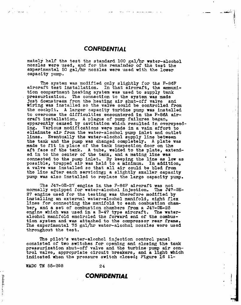
The pilot's water-alcohol injection control panelconsisted of two switches for opening and closing the tankpressurization shut-off valve and the turbine-pump air con-trol valve, appropriate circuit breakers, and a light whichindicated when the pressure switch closed; Figure 16 il-.
WADC TN 55-298 24
CONFIDENTIAL
CONFIDENTIAL
@
0 S
FIGURE 16. J47-GE-27 Engine Water-Alcohol InjectionControl Panel On The Left Forward ConsoleIn The Cockpit Of The F-86F Aircraft.
FIGURE 17. F-86F Tail-Pipe Tab i-issembly TjtilizedIn The J47-GE-27 Engine Water AlcoholInjection Testing.
WADC TN 55-298 25f't*M flD•tU

CONFIDENTIAL
lustrates the water-alcohol injection control presentationlocated in the cockpit. To initiate water-alcohol injec-tion, the tank was first pressurized. After at least 15seconds the water-alcohol injection control switch wasmoved to PRIME and held, energizing the circuit to the aircontrol valve providing the float switch was closed. Thefloat switch was a safety feature installed to preventstarting the pump until there was a head of water-alcoholat the pump inlet. A air bleed valve was used in conjunc-
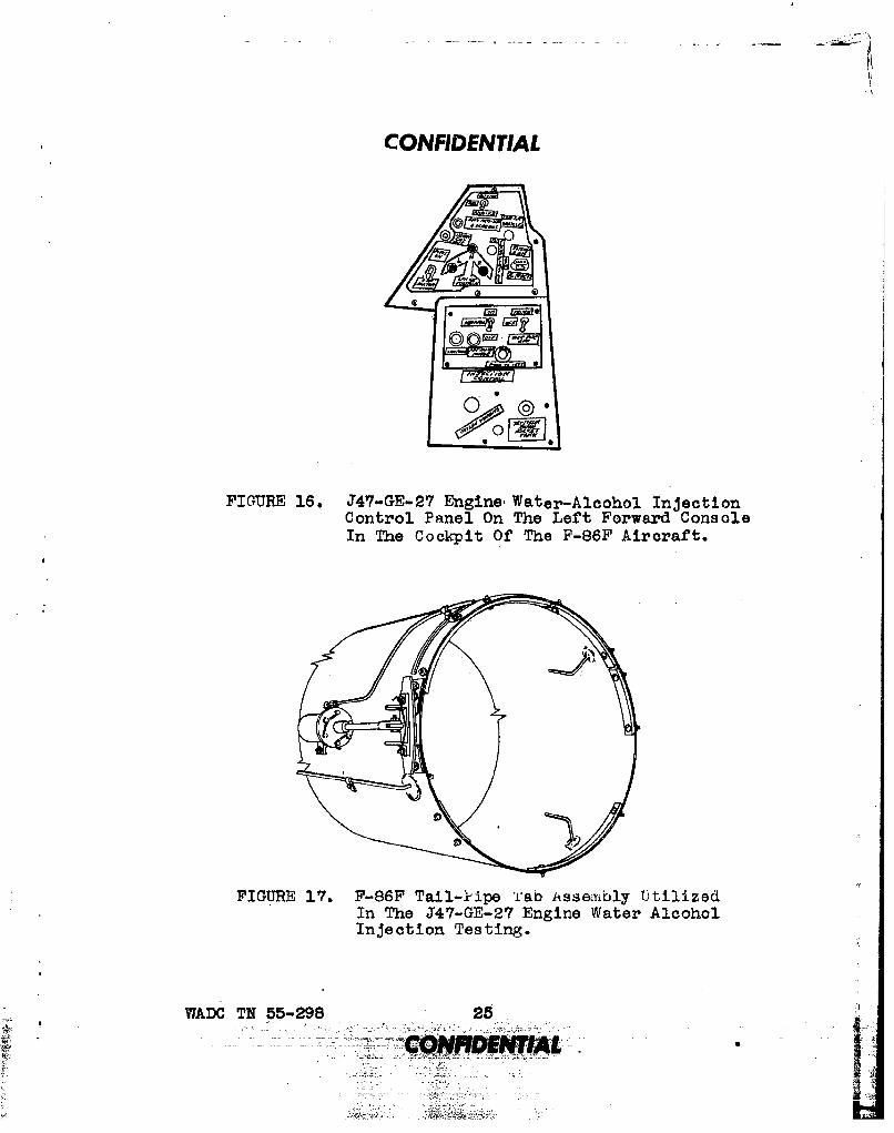
* tion with the float valve to allow air to escape. Pros-surization of the water tank forced water into the floatvalve assembly, raising the float and closing the switch.and at the same time closing the bleed valve. When themotor on the air control valve was energized, the valveopened allowing compressor discharge air to energize theturbine pump. As soon as pump discharge pressure was 10psi greater than combustion chamber pressure, water-alco-hol was forced through the check valve and injection wasstarted. Simultaneously the exhaust nozzle tabi which wasnecessary to maintain temperature, was forced up into theexhaust stream by the force of the pump discharge pressureon the piston in the nozzle actuator. Figure 17 illustratesthe tab assembly used for the testing. As soon as thewater-alcohol pressure reached the pre-selected pressureswitch setting it closed the switch energizing the pilot'sindicator light and completed an alternate circuit to theair valve.The pilot then released the switch and water-alcohol injection coptinued until thepump discharge pres-sure dropped to the level at which the pressure switch wasset to open. Opening of the pressure switch de-energizedthe air valve and stopped the airflow to the pump. If thepilot desired, he could stop water-alcohol injection bymoving his control switch to the OVERRIDE OFF position;otherwise, the injection continued until the water-alcoholmixture was expended.
In 35 flight hours on the test F-86A aircraft, approxi-mately three (3) hours of water-alcohol injection time wasaccumulated. For the test F-86F aircraft, in nearly 50hours of flight testing, over three (3) hours of water-alco-hol injection was accomplished. Many more hours of water-alcohol injection were accumulated during ground tests andsome initial flight testing utilizing a B-45 aircraft wasaccomplished.
WADC TN 55-298 26CONFIDENTIAL

CONFIDENTIALC. Results
In general, the first water-alcohol flight tests uti-lizing a single J47 engine of a B-45 aircraft were success-ful and most promising. A difficult task came however withthe adapting of the system to the F-86 aircraft.
The augmentation obtained with the configuration testedin the F-86A aircraft utilizing a J47-GE-13 engine wasvery encouraging, being approximately 30% at altitudes of30,000 feet and above. No serious problems were encoun-tered, and operation was for the most part quite satisfac-tory at altitudes up to 40,000 feet. At higher altitudesthe termination of water-alcohol injection during climbsinvariably resulted in flame-outs, although level flightoperation was normal. Upon disassembly of a test J47-GE-13engine for inspection after approximately 1-1/2 hours ofwater-alcohol injection time, the combustion chamber innerliners and transition liners were found to be damaged. Thedamage was attributed to the poor and erratic spray patternexhibited by the standard water-alcohol nozzles in theJ47-GE-13 engine. During an equivalent period of operationwith lower flow capacity nozzles, no engine damage was in-curred; however, the restriction of these nozzles was sogreat that flow, and consequently augmentation, was notice-.ably reduced even with maximum power Input to the pump.Since a method of augmentation for the F-86F aircraft wasof primary interest, and because more intensive testingwas accomplished with that aircraft, further discussionwill be confined to that phase of the testing.
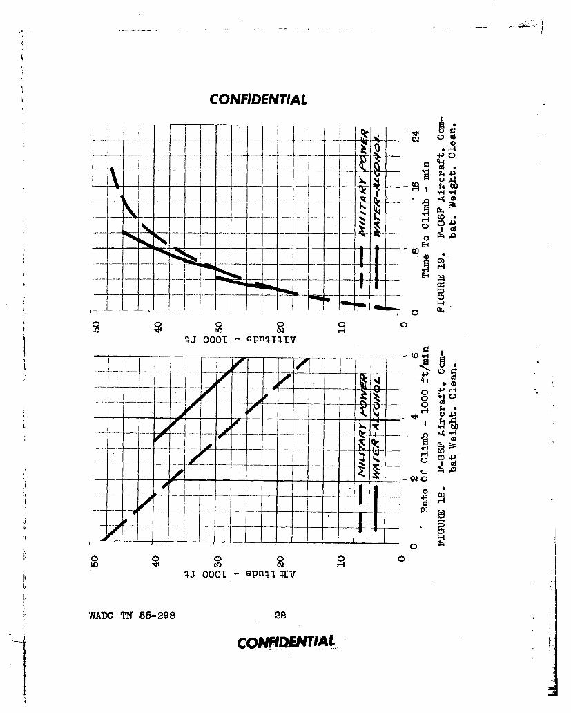
Figures 1? and 19 show comparative climb performancedata between a standard F-86F aircraft and one utilizingwater-alcohol injection. It can be observed from Figure18 that the rate-of-climb of a water-alcohol augmentedF-86F is continually increased above an altitude of 25,000feet until it is over double the dry rate-of-climb at40,000 feet. As a consequence, the time to climb from analtitude of 20,000 feet to an altitude of 30,000 feetis reduced by approximately one minute. Also, the time toclimb from an altitude of 30,000 feet to an altitude of40,000 feet is reduced by over four minutes. The reasonfor the discontinuities in Figure 19 is that a change inwater-alcohol flow rate had to be made for each range of
WADC TN 55-298 27
CONFIDENTIAL
CONFIDENTIAL
~~10
f~t t
E-
~-1-IIfrV-vE-
I~a ftt6 I~ A.iif -
0 0 0fO HQr
* ~H
I Ig d-t4
0t 0
WAflC TN 55-298 2
CONFIDENTIL.
TI.i

CONFIDENTIAL
altitudes; such a change could only be made on the ground.Figure 20 shows the increase in level flight true airspeed that was obtained by the use of water-alcohol injec-tion;: it can be seen that the speed of the F-86F was in-creased by 10 knots at an altitude of 20,000 feet and nearly15 knots at an altitude of 45,000 feet. Maximum thrustaugmentation obtained in the F-86F aircraft varied fromapproximately 19% at 20,000 feet to approximately 29% atan altitude of 40,000 feet; such data are presented inFigure 21. Since changing the water-alcohol injection ratein order to extend operation to higher altitudes was aground adjustment, the reduction in flow necessary at highaltitude resulted in less flow and less augmentation at thelower altitudes if the system was set for high altitudeoperation. The augmentation at the lower altitudes was re-duced in theorderof 20% so as to allow satisfactory opera-tion at the higher altitudes and eliminate the need for anadjustment. It was reasoned that satisfactory operation ataltitudes above 40,000 feet was worth the loss in augmenta-tion which resulted at the lower altitudes. Figure 22
,shows comparative data gathered from accelerations fromminimum level flight true air speed to maximum level flighttrue air speed at an altitude of 35,000 feet. It can benoted that with water-alcohol injection, the F-86F aircraftreaches the same maximum true air speed at an altitude of35,000 feet that was possible with an unaugmented F-86Faircraft approximately 1-1/4 minutes sooner.
More serious engine instability waa encountered with*the J47-GE-27 engine than with the J47-GE-13 engine, andalcohol ,percentages were more critical. Mixtures rangingfrom 20O to 28% alcohol were used, but with the higher per-centages there was a tendency for the engine to overspeedwhen starting or stopping water-alcohol injection. Themaximum water-alcohol flow schedule used, as shown in Fig-ure 23, which varied from 48 gal/min at an altitude of20,000 feet to 33 gal/min at an altitude of 40,000 feetgave optimum performance throughout that altitude rangewith a 24% alcohol mixture. Above an altitude of 40,000feet, that combination resulted in flame-outs when theinjection was terminated under conditions other than levelstabilized flight. By reducing the flow rate to 26 gal/mLinat an altitude of 40,000 feet, satisfactory operation wasobtained during level flight, climbs, dives, and other
WADC TN 55-298 29
CONFIDENTIAL
i'

CONFIDENTIAL
.0 Q-4H
p0
000, H
-~E jcojjji
z Iq
o00 0 0Lov ) cQ
;i oooT a-ni1,0
-~ .- -,- - .L.
op - -.ILf
C') ar+4
000 0 0 0
41 0001 -epuq~qlv
WADC TN 55-298 .30
CONFIDENTIAL

CONFIDENTIAL -
.G t
OFO
'144H co2
oD4jAO t- a))
I, CQ)-- 4-
JQ '0C*Q
1 4; He0
F4 L
C-4 9
oHb
00:
HH'
LO O 8tni lod aw .tGynxz to
WADC TN 55-298 3
CONFIDENTIAL.
CONFIDENTIAL
maneuvers at altitudes up to 48,000 feet; only one climbwas continued to an altitude of 50,000 feet. Operationabove 45,000 feet necessitated that the pilot more closelymonitor the exhaust gas temperature so as to keep it withinlimits. Also at altitudes of 45,000 feet and above therewas usually surging in engine speed when water-alcohol in-jection was initiated but throttle adjustment could allevi-ate the problem. The single exhaust nozzle tab, as-located,
* caused an objectionable yaw force, but it was thought thatby a redesign or the symmetrically locating of twin tabswould eliminate the trouble.
It was concluded that the normal combustion systemcomponents of the J47-GE-27 engine have a water-alcohol in-jection endurance life of approximately two hours. It isnoted from the forgoing discussion that water-alcohol aug-mentation of the J47-GE-27 engine in the F-86F aircraftoffered substantial gains in performance. With the excep-.tion of the 105 gallon fuel tank converted to carry water-alcohol, the configuration tested was satisfactory; asingle aircraft under-fuselage tank was designedfalthoughnever tested,to overcome that difficulty. It was apparenthowever that some additional testing was necessary. It wasalso apparent that even with ultimate refinement, the grossweight of the aircraft would be considerably increased. Oneproblem tha4 appeared difficult in light of the fact thatoperation was to be in Korea, was that of logistics, Itwas decided that a met~wd'augmentation that did not requireanother fluid and therefore not necessitate a duel tanksystem would be the most desired, thereby, allowing flexi-bility from mission to mission or as the need oceured duringany one mission. Since it was not possible to support ahigh-priority effort on more than one project, it wasconcluded that pre-turbine injection, which looked promis-ing on the basis of preliminary analysis, would be concen-trated on and that further work on water-alcohol injectionwould be continued on a. development basis with direct appli-eating being aimed at the B-47 aircraft for take-off only,where the control problems would necessarily be less. Itwas felt that a water-fuel injection system might be used.With such a system JT-4 would be substituted for the alco-hol.
WADC TN 55-298 32
CONFIDENTIAL

CONFIDENTIAL
SECTION V
PRE-TURBINE INJECTION
A. General
One of the most popular means of augmenting the thrustof a turbojet engine is afterburning. An afterburner forthe J47 engine had already undergone some development test-ing as early as February 1948; this afterburner developmentengine was designated the XJ47-GE-5. Further developmentof that engine led to the J47-GE-17 engine which powers theF-86D Aircraft and eventually to the J47-GE-33 engine. TheJ47-GE-17 and the J47-GE-27 engine were by no means inter-changeable. Even provided it would have been possible toinstall a conventional afterburner in the F-86F aircraft,the added pressure losses when non-afterburning would havereduced the aircraft's cruising range. Since the cruise-out portion of the missions in Korea were lengthy, the useof a conventional afterburner would show a disadvantagefrom that viewpoint.
A method of afterburning was necessary which would, inaddition to providing the increase in thrust necessary, alsobe capable of being incorporated in the existing aircraftwith little modification and also be such that the dry en-gine performance of the aircraft would not be affected.With such rigid requirements, only pre-turbine injectionseemed feasible. Pro-turbine injection (hereafter referredto as PTI) is a system of reheat whereby the fuel for after-burning is injected upstream of the turbine in contrast tothe conventional method of injecting the fuel for after-burning downstream of the turbine. With such a system theturbine wheel acts as a flameholder rather than havingseparate flameholders which contribute to the dry loss ofan afterburning engine. PTI, which in a liberal sensemight be referred to as an extremely short afterburner,allowed the combining of the diffuser and burner sectionsinto one and therefore made installation in the alreadyexisting F-86 aircraft possible. The first work on sucha system was conducted in Germany as early as October 1939.The first successful tests were run on the German Jumo 004turbojet engine in 1942. Later, although prior to the out-
WADC TN 55-298 33
CONFIDENTIAL

CONFIDENTIAL
break of hostilities in Korea, a series of similar testswere conducted on Americin engines of a later design in thePower Plant Laboratory, Wright Field.
Many of the problems which had to be resolved duringPTI development and testing were similar to problems whichwere encountered in previous afterburner developments.These problems however were aggravated by the limitationsplaced on the system in the form of weight and availablespace restrictions. Since PTI was to be installed in theF-86F aircraft, a rather large portion of the testing hadto be centered around obtaining adequate cooling of theaircraft structure. Two test aircraft were used, one wasdevoted to engine testing and the other toward resolvingthe problems associated with the installations.
B. Testing
Thrust augmentation during PTI operation was obtainedby a combination of afterburning and basic engine overtem-perature operation. Naturally basic engine overtemperaturewas undesirable but it was nevertheless necessary becauseof the space limitations in the aft fuselage of the F-86airdraft. Had space been available, a larger tail-pipe andnozzle could have been utilized, much like a conventionalafterburner, and the increase in back pressure on the en-gine due to afterburning could have been reduced. It isnoted that afterburning has much the same effect as closingthe exhaust nozzle of an engine. A decrease in the exhaustnozzle area increases the back pressure on the turbinewhich reflects forward through the engine to the compressoroutlet, resulting in an increase in compressor pressureratio. In order to maintain the additional work from theturbine that is required to maintain engine operation atthis increased compressor pressure ratio condition, theturbine inlet temperature must be increased. Such was thecase with PTI where it was not possible to increase the ex-haust nozzle area as much as was desired and still main-tain stable burning. Without overtemperature, the enginerpm would continually drop off with increasing altitude.The degree of engine overtemperature for which the PTIsystem was designed was based upon an estimated five hourturbine bucket life. However, in order to bbtain stablePTI burning, it was necessary to operate at augmentationratios higher than those originally intended with a conse-
WADC TN 55-298 34
CONFIDENTIAL

CONFIDENTIAL
quent adverse effect on engine life. A variable-area exhaustnozzle was used to maintain the correct combination of pres-sure and temperature for stabilized PTI burning in the engineexhaust section as well as to provide the correct nozzle areafor dry engine operation. In order to minimize control sys-tem design complexities and to maintain the fuel flow require-ments within the capacity of the existing fuel pumps, PTIoperation was limited to altitudes above 20,000 feet. Suchrequirements which would allow operation below an altitudeof 20,000 feet were beyond the limits of the equipment usedin the PTI system.
The PTI system is shown schematically in Figure 24.Fuel for pre-turbine injection was supplied from the normalaircraft fuel system by the standard engine emergency fuelpump. A PTI metering valve regulated the fuel flow inaccordance with the pressure schedule set by the EC-2 emer-gency fuel regulator normally provided on the engine. Themetered PTI fuel was injected into the gas stream by meansof four probes located in alternate combustion chambertransition liners forward of the turbine nozzle. The fuelvaporized and burned downstream of the turbine wheel. Opera-tion was such that flameholders were not thought necessary.Naturally when the correct combination of pressure, tempera-ture, and fuel-air ratio occurred, burning would take place.The fuel in order to burn had to enter a zone that wouldcontinually meet the combustion requirements. Thus theconditions at turbine outlet had to meet such requirements.Should combustion not have taken place, the pTI fuelwould have merely passed out through the engine unburned.Once lit, the flame did not progress upstream as the gasvelocity far eýcceeded the rate of flame propagation. At
,first the system utilized a hot streak ignition system butsubsequent flight tests demonstrated that it was unnecessaryfor satisfactory light offs. Initial flight testing wasaccomplished using a water injection type tab to vary theexhaust nozzle area pending development of a suitablevariable-area nozzle and nozzle control. Early tests wererun with the standard F-86F tail-pipe and it was not ade-quate due to the high failure rate. Numerous tests, withtail-pipes constructed of various materials and thicknesses,were conducted. Since failures were caused by excessivetemperature of the tail-pipe skin, some method of loweringthe skin temperature was sought. The initial testing wasconducted with an insulation blanket surrounding the tail-pipe. Radiation heat shields were added to several major
WADC TN 55-298 35
CONFIDENTIAL

+II
CONFIDENTIAL"
r+ 0
cl)
iri in•-m-E.-- Ji +
~cQ
Lwi T•. I 55-298 w
CONFIDENTIAL

CONFIDENTIALaircraft frames and local cooling was provided for the aftcanted frame. Ram air scoops were incorporated to increasethe cooling airflow throughthe aft fuselage. High tail-pipe skin temperatures measured during flights indicatedthat a blanketed tail-pipe configuration was unsuitableand that the temperature could be lowered by about 1500 to2000F by their removal. The tailpipe blankets were thusreplaced by a silver plated shroud. The cooling problemwas made difficult by the partial loss of ejector actiondue to the decrease in secondary air area as a result ofinstalling a variable-area nozzle which was necessarilylarger than the standard tail-pipe's nozzle. Further re-duction in the temperatures to which the tail-pipe wasexposed became possible with the introduction of a corru-gated louvered liner. The liner was installed for bettercooling and not to prevent screech since that problem wasnot present. The liner was identical in construction, al-though not in size, to the liner in the afterburner of theJ47D series engines used in the F-86D aircraft. Tail-pipeconstruction was revised to include a flex joint betweenthe engine tail-cone and tail-pipe to eliminate the highoverhana moment of this tail-pipe configuration.
A by-pass fuel line with a variable trimmer valve wasspecially provided between the engine small and large slotmanifolds to increase the basic engine fuel flow duringPTI operation. A solenoid shut-off opened the by-pass linewhen PTI was selected. The variable trimmer valve is ametering device which varies the by-pass flow in accordancewith small slot fuel pressure, closing completely aboveapproximately 45,000 feet altitude where the main engineregulator fuel schedule is adequate to supply engine fueldemands. A second special by-pass fuel line with a groundadjustable trimmer (needle valve) was provided between thesmall and large slot manifolds for ease in adjusting theengine acceleration schedule on the ground.
After a review of many variable-area nozzle configura-tions, the flat plate orifice type appeared to best suitall needs since it was simple and relatively light in weight.Activation was obtained at a single circumferential pointthus reducing the space requirements. Actuation loads wererelatively light since only friction had to be overcome.The power source for the nozzle was a 1/6 horsepower air-
WADO TN 55-298 37
CONFIDENTIAL

CONFIDENTIAL
frame mounted electric motor. The motor actuated a ballbearing Jack screw mounted on the nozzle housing. Figure 25is a sketch of the nozzle arrangement. It was found thatone nozzle position would suffice for PTI operation but twowere needed for dry operation; this was due to the factthat the flow coefficient and effective areas varied appreci-ably at the low actual values. There were two possible waysof compensating for the variations of these factors -- con-stantly variable or a step control nozzle. The simplestmethod and also the most advantageous from a developmenttime standpoint was step control. Ideally, for the mosteffectively controlled engine, a constantly variable-areanozzle was desirable since any use of a step control wouldnecessarily compromise performance. It was decided thatonly a fully variable-area nozzle would be satisfactory,for with a step control a three position nozzle was neces-sary; one for take-off, one for climb and normal performanceat altitude, and one for PTI operation.
The fully variable-area nozzle used in conjunctionwith PTI was controlled by a pressure sensing device knownas the Micro-Jet. The unit controlled turbine dischargetemperature by varying the nozzle position to maintain aconstant pressure ratio across the turbine for any givenoperating condition. The Micro-Jet contained a diaphragm,one side of which was exposed to turbine discharge pres-sure through a sensing line. The other side of the dia-phragm was exposed to a pressure which was controlled bybleeding compressor discharge air through a fixed inletorifice and a variable discharge orifice. The fixed ori-fice was analogous to the engine's turbine and the orificesize was ground adjustable to give the proper turbinepressure ratio (determined by turbine discharge temperature).The second orifice simulated the variable-area exhaustnozzle. A tapered needle in the variable orifice was auto-matically positioned by the diaphragm to relieve any pres-sure differential across the diaphragm by increasing ordecreasing the pressure drop through the orifice. Shouldthe needle be disturbed from its neutral position (deter-mined by the pre-set turbine pressure ratio) by a pressuredifferential across the diaphragm, the electrical contactsof the Micro-Jet would close signalling an electrical con-trol box to energize the nozzle actuator motor to eitherclose or open the exhaust nozzle (depending on the direc-tion of needle movement). The nozzle closed or opened
WADC TN 55-298 38
CONFIDENTIAL
7 -

'I CONFIDENTIAL
FIGURE 25. F-86F Tall-Pipe Variable Area Nozz.leUtilized In The J47-GE-27 Engine Pre-Turbine Fuel Injection Tests.
FIGURE 26. J47-GE-27 Engine Pre-Turbine FuelInjection Control Cockpit PresentationIn The F-86F Aircraft.
WADC TN 55-298 39
CONFIDENTIAL

CONFIDENTIAL
until It reached a position which restored the turbine pres-sure ratio to the value determined by the neutral positionof the needle.
A solenoid operated bleed valve on the compressor dis-charge pressure side of the Micro-Jet diaphragm, which wasopen during dry operation and closed during PTI operation,permitted engine operation on two different turbine pres-sure ratios thus allowing the control to be used for bothdry and PTI operation. Since retarding of the throttle be-low its military power lowered the turbine pressure ratio,the control tended to open the nozzle as the throttle set-ting was reduced. The light-off problem at altitude wasconsiderably alleviated with the introduction of the Micro-Jet control.
A PTI pressure out-out switch was provided as a meansof de-energizing the PTI circuit to prevent engine over-speed should override of the main fuel control system bythe emergency fuel control system have occurred during PTIoperation. Figure 26 is a sketch of the PTI presentationin the cockpit. PTI operation was initiated by the pilotfirst setting the guarded PTI ready switch to ON, he thenset the nozzle selector switch to AUTOMATIC and then fol-lowed by moving the throttle to the military power positionand then momentarily outboard from the military power de-tent. PTI light-up and operation was fully automatic fol-lowing the above three step procedure. However, the pilothad to observe the PTI exhaust gas temperature limit of12000 C during PTI operation. If the temperature approachedthe limit, the throttle had to be retarded. PTI would re-main in operation until the throttle was retarded to the96% rpm position, but below 96% rpm PTI was automaticallyshut off. If for any reason the pilot wished to stop PTIoperation, either the PTI ready switch could be positionedto OFF or the throttle retarded past the 96% rpm position.
During 894 hours of static testing, 117 hours of PTIwere accomplished. In addition 46 hours of testing wereaccomplished in an altitude tank with 8 hours of PTI beingaccomplished. A total of 209 flights were conducted uti-lizing two aircraft; during the 135 hours of flight testing,17 hours of PTI were accomplished. A single 50 hour endur-
WADC TN 55-298 40
CONFIDENTIAL
S4.

CONFIDENTIAL
ante test and three consecutive 50 hour tests were run.During the single 50 hour endurance test 100 minutes of PTIwere accomplished. Five hours of PTI were accomplishedduring the three consecutive 50 hour tests. The maximumaltitude reached during the testing was 53,760 feet. Twelveflights were conducted above an altitude of 50,000 feet and26 flights were conducted above an altitude of 45,000 feet.
C. Results
PTI applied to the J47-GE-27 engine in the F-86F air-craft considerably improved the weapon's performance.Pertinent data concerning PTI are shown in Figures 27through 34. Also shown are performance data for a produc-tion F-8G6F aircraft for purposes of comparison.
As can be seen from Figure 27, the rate-of-climb ofthe F-86F aircraft using PTI, as compared to a standardunaugmented F-86F, was more than doubled at an altitude of35,000 feet, tripled at an altitude of 40,000 feet and wasincreased by as much as four times at an altitude of 45,000feet. Thus the time to climb from an altitude of 20,000
"* feet to an altitude of 45,000 feet was reduced by over sixminutes, the comparative times to climb being approximately4 and 10 minutes for a PTI equipped aircraft and a produc-tion aircraft respectifully. A PTI climb could be madefrom an altitude of 20,000 feet to an altitude of 50,000feet in approximately 6 minutes; Figure 28 presents suchdata. The maximum level flight true air speed ofthe F-86Faircraft was increased in the order of 20 to 25 knots be-tween altitudes of 20,000 and 45,000 feet; Figure 29 showsthis increase. The thrust augmentation obtained by usingPTI, as can be seen from Figure 30, showed as average in-crease of about 45% over the 20,000 to 45,000 feet altituderange. As a result of PTI, a substantial improvement inacceleration was made possible as evidenced from Figure 31.Thus with PTI, the maximum level flight true air speed ofa production F-86F aircraft at an altitude of 35,000 feetwas reached over one minute sooner. Figure 32 is & com-pilation of specific fuel consumption data; the Figure showsthe rather large increase in specific fuel consumption withaltitude when using PTI. As can be observed, the unaug-mented J47-GE-27.engine's specific fuel consumption is near-ly constant over the complete altitude range while the spe-
WADC TN 55-298 41
CONFIDENTIAL
CONFIDENTIAL
o~
020+
43
;000- c- - 4-0 Q 00000
1 j o V
as CQa
00 0 0Lo~- 14f o Q
qj 001 epq~ql
WADC N 55-98 4
-CONFIDENTIA

CONFIDENTIAL
o~~ H~.A 0001 (pd ~1
"-o - - - I -l o +pf
000
000 0
00 00m-etTt
0D 0N 550 40CONFIDENTIA
qjoo pTa

CONFIDENTIAL
A i0 , g
4-3
&00 WA40
CrQ
• i mr-i j~
4j.. OOO opnTqPr'
t Ho 0 0 0 0 0
10 -C'-
WAD- TN 55-298 44.CONFIDENTIAL

CONFIDENTIAL,
cific fuel consumption, utilizing PTI, increases due to thenecessity of having to increase quite substantially thefuel flow at the higher altitudes. Nevertheless, the spe-cific fuel consumptions obtained with PTI were considerablybetter than those obtained with a standard afterburning en-gine; for instance, the J47-GE-17 engine which powers theF-86D aircraft has a specific fuel consumption approximately40% greater than a PTI equipped J47-GE-27 engine. It wasconcluded that the combat fuel requirements of PTI wouldnot impose a serious operational limitation; the combat radi-us of the F-86F aircraft utilizing PTI was reduced evenless du6 to the addition of the increased weight of thesystem. The J47-GE-17 engine utilizing a standard after-burner gives a higher augmentation ratio than the PTIequipped J47-GE-27, but also at a cost of nearly five timesthe weight. With PTI, there was an increase in aircraftweight of 140 pounds. The PTI kit itself actually weighed210 pounds; however 70 pounds of existing parts were de-leted. For instance, the tail-pipe and nozzle included inthe kit replaced those already in the aircraft. The after-burner of the J47-GE-17 engine alone weighs 655 pounds.
A pronounced improvement in airplane maneuverability,as can be observed from Figures 33 and 34 was possiblewith the additional thrust provided by PTI operation. Al-titude turns and maneuvers with PTI could be performedwith less drop-off in speed and altitude. Also, constantaltitude, constant speed maneuvers could be accomplishedwith higher load factors and reduced turning radia withFTI. One disturbing factor arose however due to the addedweight of the PTI installation. The addition of the PTIinstallation plus. ballast, combined with the expenditureof ammunition and fuel sequencing produced unacceptableloading conditions. With the PTI system tested, 150 poundsof ballast were required to provide the same acceptableaircraft balance as an unmodified aircraft. The addedweight of the PTI installation caused a rearward shift ofthe aircraft's center of gravity such that it exceededthe aft neutral stability limits when the ammunition wasexpended and thus the ballast in the nose of the aircraftwas necessary to correct that condition; but, when theballast was added and the ammunition was retained, thecenter of gravity shifted forward to its maximum in-flightposition. The net result being an approximate 15% reduc-
WADC TN 55-298 45
CONFIDENTIAL
y1

CONFIDENTIAL
0 4.,
It)
0 1 04-)
_ 'CVe
f0 0
41J 0001 - tZrL. Jo sr~v
o 00H14- H H
- .zo~o~ p~V)
WADC00 TNIt')9 4
-0-

CONFIDENTIAL
tion in the aircraft's maximum allowable load factor. Itwas felt that with the addition of the proposed 12 inch wingtip extension, the 150 pound ballast could be deleted. The12 inch wing tip extension would allow an approximate 3% im-provement in aircraft stability.
The degree of engine overtemperature for which the PTIsystem was designed was based upon an estimated five hourturbine bucket life. However, in order to obtain stablePTI burning at the higher altitudes, it was necessary tooperate at augmentation ratios higher than those originallyintended with a consequent adverse effect on engine life.Nearly 40% of the augmentation obtained was due to over-temperature of the basic engine itself. Turbine bucketsduring the test program had to be replaced nearly every onehour of PTI operation. The buckets were replaced becauseof excessive growth or actual failure. It was necessaryto replace the turbine wheel after approximately three hoursof PTI operation. Throughout the entire test program, fiveturbine wheel failures were experienced and several otherswere rejected after inspection. The exhaust-cone and tail-pipe had to be replaced on the average of about once everytenth flight. Some difficulty was experienced with thevariable-area nozzle as it had a tendency to stick; thedifficulty was overcome by hardening of the segments.Burner roughness was found at altitud~es near 50,000 feet,but in general the entire system functioned satisfactorilyand burning and light-ups were smooth. One very greatproblem centered around the obtaining of the proper fuelscheduling and many flights were ac'omplished to obtainsatisfactory operation, particularily at the higher alti-tudes. Since the EC-2 standard emergency fuel regulatorwas used as th6 PTI fuel metering device, maintaining aclose tolerance on the fuel injection rate was impossibleand that complicated with the narrow operating range of theburner at high altitudes made the problem more difficult.Although the emergency fuel regulator was part of the PTIsystem, normal operation of the emergency fuel system waspossible.
A large portion of the test program was concerned withdetermining an adequate configuration for the aft fuselagesince PTI operation necessarily overheated the aircraft's
WADC TN 55-298 47
CONFIDENTIAL

CONFIDENTIAL
structure in that section; cooling air inlet and outletscoops were added to the aft canted frame in addition tostiffener plates in two places on the inner side and strapsin three places on the outside. It was also necessary toremove a lower portion of the aspiration as well as to addheat reflecting shields. Access doors were placed to al-low servicing and adjustment of the nozzle actuator. Acomplete satisfactory configuration for the aft fuselage wasdeveloped and a service bulletin was formulated. One ofthe design objectives of the PTI systems was that it mightallow installation in the field; such an objective was re-alized but approximately 600 man-hours would be necessaryfor the installation and rework operation.
The severe reduction in parts life was obviously thegreatest deterrent to the use of PTI. It was estimatedthat it would be possible to perform six missions, utiliz-ing 6 to 10 minutes of PTI per mission, before it would benecessary to replace turbine buckets. In addition, atleast one of the PTI missions would be necessary to check-out and adjust the system; particularly critical was thedetermining of the proper fuel schedule for operation abovean altitude of 45,000 feet. Near the end of the testingprogram, some work was accomplished utilizing flameholdingelements in an effort to increase the life of the turbinebuckets which had previously served the purpose of flame-holders.
WADC TN 55-298 48CONFIDENTIAL

CONFIDENTIAL
SECTION VI
GENERAL CONCLUSIONS
Without overtemperature, no increase in thrust is madepossible through overspeeding the rotor of the J47-GE-13engine.
Imnediate thrust augmentation of the J47 engine may beobtained through overtemperature operation. Such overtempera-ture operation requires only the decreasing of the exhaustnozzle area by placing restrictor segments in the tail-pipe.This tabbing operation i easily accomplished and requiresonly a small expenditure of work. Other than the decreasein the life of the engine's hot parts subjected to overtem-perature, engine operation is unaffected throughout the en-tire operational range of the F-86 aircraft. The rate-of-climb of the F-86E aircraft may be increased by as much asfour times at an altitude of 45,000 feet by overtemperaturing 'the J47-GE-13 engine by 18%. At lower altitudes, the increase"in the rate-of-climb of the F-86 aircraft resulting fromovertemperature operation will not be as pronounced. Over-temperature operation of the J47-GE-13 engine may be safelyutilized for a maximum period of ten minutes before a hotparts inspection and turbine bucket replacement is necessary.Overtemperature operation of the J47-GE-27 engine in theF-86F aircraft is expected to offer a slightly lower increase.in performance, relatively speaking when compared with the
J47-GE-13 engine in the F-86E aircraft due to the formersinitially better altitude characteristics; hot parts' lifewould also tend to increase slightly as the J47-GE-27 engineincorporates improvements in its hot section.
Liquid nitrogen injection into the J47 engine is notpracticle for use in the F-86 aircraft. Further work withcompressor refrigerant injection should be carried out onadvanced engines as it would undoubtedly prove worthwhilefor supersonic applications.
Many factors combine to make water-alcohol injectioninto the J47 engine undesirable for use in the F-86 aircraftalthough substantial increases in performance were demonstratedin flight tests. The necessity of having a dual tank system
WADC TN 55-298 49
ý CONFIDENTIAL

° CONFIDENTIAL
and the lack of a~n adequate fluid injection metering controlwould compromise the overall performance of the P-86 aircraft.Without further development of the water-alcohol injectionsystem, unsatisfactory operation of the engine could be ex-pected above an altitude of 45,,000 feet. Installation of awater-alcohol injection system into the F-86 aircraft is a.major task although no redesign of the aircraft structure isnecessary. The J47 engine may be expedited to hold up undertwo hours of wsa-,.er-alcohol injection before an inspection isnecessary.
Pre-tutrbine fuel injection met all Initial performanceexpectations with the exception of hot parts' life. Opera-tion of the PTI system In the F-86 aircraft is satisfactoryup to an altitude of 45,000 feet and may be considered mar-ginally satisfactory above that to altitudes slightly in ex-cess of 50,000 feet. The rate-of-climb of the F-86F aircraftis increased over four times at altitudes greater than 45,000feet and the maneuverability and overall performance of' theAircraft is increased substantially above an altitude of20,000 feet. 0vertemperature operation of the basic engineduring pre-turbine injection alone provided nearly 40% ofthe total augmentation provided by PTI and although the PTIportion of the system can have a reasonably lengthy parts!life, the basic engine's hot parts would be limited to lessthan one hour of PTI operation. The PTI system may be in-stalled in the field as installation criterion is availablein service bulletin form, however, it might pose somewhatof a task and installation had better be accomplished at adepot. Fsrther work on a system employing the pre-turbineinjection principle is warranted although utilizing a moremodern engine than the J47. Such a system offers a meansfor achieving a low dry loss, light weight afterburning systemwhich could possibly find application for take-off purposesthereby not encountering the usual difficulty with after-burning at altitude and also necessitate only a mlhimum ofcomplication through control requirements. Work should bedirected toward Improving the vaporization cooling of theturbine through better fuel distribution and the investiga-tion of flameholders, possibly of the retractable type.Interstage turbine fuel injection on multistage engines should ibe further Investigated. Such work by the U.S. Navy, utiliz-..Ing a J46 engine, haLs been relatively unsuccessful to date.
WADC TN 55-298 50
CONFIDENTIAL i

CONFIDENTIAL
Means of increasing the performance of the F-86 air-craft were demonstrated through the program and such meanswould have considerably enhanced the aircraft's combat cap-ability as may be observed by superimposing the previousdiscussed data upon similar data of the MIG-15 aircraftgiven in the appendix for comparative purposes. However,the most serious deterrent to the possible use of any ofthe augmentation systems brought under development in theprogram was the severe reduction in engine parts' lifewhich was brought about by their use. Although the J47engine is basically a reliable, easily maintainable engine,which can take considerable maltreatment, it is prone toturbine wheel failures and any operation which subjects theengine to overtemperature should only be resorted to in direemergencies. Attacking the problem at its source, by pro-viding more durable basic engine hot parts, was beyond thestcope of the program.
Each phase of the project was typlified by rapid pro-gress in the beginning with further improvements requiringintensified effort and considerable time as each system be-came more complicated and increased altitude requirementsdemanded more sophistibation. Refinement of each systemsoon reached a saturation point where returns were dimin-ishing due to the inherent limitations of the basic engineand the high density of the aircraft's structure.
It is obvious that each of the thrust augmentationmeans developed for the J47 engine In the F-86 aircraft wasof a strictly war emergency type and only suitable for usein an extreme emergency and then only when adequate logisticand maintenance support can be made available or where flightsafety or the aircraft in-commision rate can be compromisedfor the increased performance gains.
The thrust augmentation program for the J47 engine inthe F-86 aircraft demonstrated that there is no substitutefor a basically better engine which Is made available througha normal development program. This point was illustratedin the superior performance and combat record of the F-86Faircraft which uses the J47-GE-27 engine as compared to theF86E which is powered by the J47-GE-13 engine. The J47-GE-27engine is a development of the J47-GE-13 engine.
WADC TN 55-298 51
CONFIDENTIAL

II
CONFIDENTIALREFERENCES
The project's official engineering file, whichwas maintained by the Power Plant Laboratory, WrightAir Development Center served as the primary referencefor WADC TN 55-298 in addition to information gatheredfrom personnel who participated in the program. Asidefrom the project's record books, correspondence, minutes, andmemorandums, both Government' and Contractors' reports weremaintained in the file and the more significant rep-ortswhich were used as references are given below.
Air Force Flight Test Center. Altitude Thrust AugmentationUsing Water-Alcohol Injection. AF Technical Report No.A11°1•TU b6-8. March 1953. (Confidential Report)
Air Force Flight Test Center. Phase II Performance AndServiceability Tests Of The F-86F Airplane USAF No.5--13506 With Fre-Turbine Modifications. AF TechnicalReport No. AFFTC 54-16. June 1954. (Confidential Report)
General Electric Company. Flight Test Of OvertemperatureWar Emergency Power Setting On A J47-WE,13 Engine InstalledTnX' F-86e Aircraft At AFTC Edwards, California. GEBulletin No. DF52GT745. 23 June 1952. (Unclassified Report)
General Ele ctric Company. Estimated Minimum PerformanceOf The General Electric J47-GE-27 Turbojet Engine AtWar Emergency Rating With Preturbine Injection Kit.GE Bulletin No. R53AGT568. 15 September 1953.(Confidential Report)
General Electric Company. Model Specification WarEmergency Rating System Kit No. 7032R37. GE SpecificationNo,. E-641. 31 December 1953. kOonfiderti&l Specification)
General Electric Company. Pre-Turbine Fuel Injection forThrust Augmentation. GE Technical Information SeriesNo. R55AGT95. 11 March 1955. (ConfidentiAl Report)
North American Aviation, Inc. Thrust Augmentation Of AJ47-GE-1i Engine By Means Of Liquid Nitrogen InjectionInto The Compressor Inlet. NAA Report No. NA52-297.i7 dune 1952. (onhridentlal Report)
North American Aviation, Inc. F-86F Airplane With Pre-Turbine Injection (PTI) Thrust Augmentation. AJA SummaryReport No. NA-54-664. 9 Jul 1954. (Confidential Report)
VWADC TN 55-298 52
CONFIDENTIAL "

CONF/DENTIAM
National Advirory Committee For Aeronautics. (ConfidentialTitle) Altitude Investigation Of Thrust Augmentation Of A"J47-GE-27 Turbojet Engine By Injecting Additional FuelImmediately Ahead Of The Turbine. NACA Research MemorandumRM E53L31, 3B December 1953. (Confidential Report)
Air Technical Intelligence. (Secret Title). TechnicalReport TR-AC-27. 13 October 1953. (Secret Report)As the title of this report is Secret it can not begiven here. The material taken from the above reportand contained in WADC TN-55-298 is as of the writingof this TN classified Confidential.
WADC TN 55-298 53
CONFIDENTIAL I

CONFIDENTIALAPPENDJIX
- Id
'1)i 0
r 6-1
ID I fr.
7 -f
0r- 0 04
-VWADO TN 55-298 54
CONFIDENTIAL 1
5, .GLPH-10637

firmed Services lchnicalnformation Ageno.,j ýyReproduced by
DOCUMENT SERVICE 'CENTERKNOTT BUILDING, DAYTO11, 2, OHIO
This document is the property of the United States Govejinment. It is furnished for the dit.ration of the contract and shall be returned when no longer 'required, or upon recall by AST~ito the following address: Armed Services Techbacal Informzition AgencyDocument Service Center, Knott Building, Daytoa 2, Ohio.
NOTICE: WHEN GOVERNMENT OR 011HER DRAWINGS, SPECIFICATIONS OR OTHERL DAT.ARE USED FOR ANY PURPOSE OTHER THAN IN CONNECTION WrT£ A DEFXNT1ELY REL iEl:GOVERNMENT PROCUREMENT OPERATION, THE U. S. G0)VERNMENT THEREBY !NCURINO RESPONSIBILITY, NOR ANY OBLIGATION WHATSOEV1R; AND THE FACT THAT THEGOVERNMENT MAY HAVE FORMULATED, FURNISHED, CIR P'4 ANY WAY SUPPIALD THESAID DRAWINGS, SPECIFICATIONS, OR OTHER DATA It. (/.1 -1 . , j.,E
IMPLICATION OR OTHERWISE AS IN ANY MANNER LIC Z.8iNG THF HC%,Dra, OF, ANY 4y"; -PERSON OR CORPORATION, OR CONVEYING ANY RIG]•r,T OR PERMISSION TO MIN-UFAt J14USE OR SELL ANY PATENTED INVENTION THAT MAY 2 .ANY WAY BE RELATED '!iH:> ,
Ad=~~ 11111AN% n

DEPARTMENT OF THE AIR FORCE
HEADQUARTERS AIR FORCE MATERIEL COMMAND
WRIGHT-PATTERSON AIR FORCE BASE OHIO
FEB t 9 2002
MEMORANDUM FOR DTIC/OCQ (ZENA ROGERS)8725 JOHN J. KINGMAN ROAD, SUITE 0944FORT BELVOIR VA 22060-6218
FROM: AFMC CSO/SCOC4225 Logistics Avenue, Room S 132Wright-Patterson AFB OH 45433-5714
SUBJECT: Technical Reports Cleared for Public Release
References: (a) HQ AFMC/PAX Memo, 26 Nov 01, Security and Policy Review,AFMC 01-242 (Atch 1)
(b) HQ AFMC/PAX Memo, 19 Dec 01, Security and Policy Review,AFMC 01-275 (Atch 2)
> (c) HQ AFMC/PAX Memo, 17 Jan 02, Security and Policy Review,AFMC 02-005 (Atch 3)
1. Technical reports submitted in the attached references listed above are cleared for publicrelease in accordance with AFI 35-101, 26 Jul 01, Public Affairs Policies and Procedures,Chapter 15 (Cases AFMC 01-242, AFMC 01-275, & AFMC 02-005).
2. Please direct further questions to Lezora U. Nobles, AFMC CSO/SCOC, DSN 787-8583.
LEOrRA U. NOBLESAFMC STINFO AssistantDirectorate of Communications and Information
Attachments:1. HQ AFMC/PAX Memo, 26 Nov 012. HQ AFMC/PAX Memo, 19 Dec 013. HQ AFMC/PAX Memo, 17 Jan 02
cc:HQ AFMC/HO (Dr. William Elliott)

DEPARTMENT OF THE AIR FORCE
HEADQUARTERS AIR FORCE MATERIEL COMMANDWRIGHT-PATTERSON AIR FORCE BASE OHIO
MEMORANDUM FOR HQ AFMC/HO
FROM: HQ AFMC/PAX
SUBJECT: Security and Policy Review, AFMC 02-005
1. The reports listed in your attached letter were submitted for security and policy review IAWAFI 35-101, Chapter 15. They have been cleared for public release.
2. If you have any questions, please call me at 77828. Thanks.
ESJ E A. MRO3ecurity and Policy Review
S~Office of Public Affairs
Attachment:Your Ltr 14 January 2002
14 January 2002
MEMORANDUM FOR: HQ AFMC/PAXAttn: Jim Morrow
FROM: HQ AFMC/HO
SUBJECT: Releasability Reviews
1. Please conduct public releasability reviews for the following attached DefenseTechnical Information Center (DTIC) reports:
a. Flight Test Program for Model P-86 Airplane Class - Jet Propelled Fighter, 2December 1946; DTIC No. AD-B804 069.
b. Physiological Recognition of Strain in Flying Personnel: Eosinopenia in F-86Combat Operations, September 1953; DTIC No. AD- 020 375.
c. Phase IV Performance Test of the F-86F-40 Airplane Equipped with 6x3-inchLeading Edge Slats and 12-inch Extensions on the Wing Tips, May 1956; DTICNo. AD- 096 084.
d. F-86E Thrust Augmentation Evaluation, March 1957; DTIC No. AD- 118 703.
e. F-86E Thrust Augmentation Evaluation, Appendix IV, March 1957; DTIC No.AD- 118 707.
f. A Means of Comparing Fighter Effectiveness in the Approach Phase, October1949; DTIC No. AD- 223 596.
g. War Emergency Thrust Augmentation for the J47 Engine in the F-86 Aircraft,August 1955; DTIC No. AD- 095 757.
h. Operational Suitability Test of the F-86F Airplane, 4 May 1953; DTIC No. AD-017 568.
i. Estimated Aerodynamic Characteristics for Design of the F-86E Airplane, 26December 1950; DTIC No. AD- 069 271.
j. Combat Suitability Test of F-86F-2 Aircraft with T-160 Guns, August 1953; DTICNo. AD- 019 725.

2. These attachments have been requested by Dr. Kenneth P. Werrell, a private
researcher.
3. The AFMC/HO point of contact for these reviews is Dr. William Elliott, who may be
reached at extension 77476.
kJOHN D. WEBERCommand Historian
10 Attachments:a. DTIC No. AD-B804 069b. DTIC No. AD- 020 375c. DTIC No. AD- 096 084d. DTIC No. AD- 118 703e. DTIC No. AD- 118 707f. DTIC No. AD- 223 596g. DTIC No. AD- 095 757h. DTIC No. AD- 017 568i. DTIC No. AD- 069 271j. DTIC No. AD- 019 725