new gen iii+ reactor power plant designs economic ... · power plant designs economic simplified...
TRANSCRIPT

ESBWR Overview 1Predecisional – Information compiled from public sources – Internal ORNL use only
March 2006
New Gen III+ Reactor New Gen III+ Reactor Power Plant Designs Power Plant Designs
Economic Simplified Boiling Economic Simplified Boiling Water Reactor (ESBWR)Water Reactor (ESBWR)
NSTD Introductory CourseNSTD Introductory Course

ESBWR Overview 2Predecisional – Information compiled from public sources – Internal ORNL use only
March 2006
Disclaimer
Information contained herein is derived exclusively from publicly available documents. The content of this introductory course does not necessarily represent what may be submitted to the Nuclear Regulatory Commission in the form of a license application for a new reactor. ORNL neither endorses this design nor has performed any design reviews to validate design improvements, design margins, or accident probabilities. The intent in compiling this information at this time is for the express purpose of constructing an internal, introductory course for our own staff.

ESBWR Overview 4Predecisional – Information compiled from public sources – Internal ORNL use only
March 2006
ESBWR
Key Design Features

ESBWR Overview 5Predecisional – Information compiled from public sources – Internal ORNL use only
March 2006
Nuclear Power Plant (NPP) Development
Gen IILarge Commercial NPPs Currently in Operation Throughout U.S.
Gen IIIAdvanced LWRs AP 600(W)
ABWR (GE)
System 80+ (CE)
ESBWR Overview 6Predecisional – Information compiled from public sources – Internal ORNL use only
March 2006
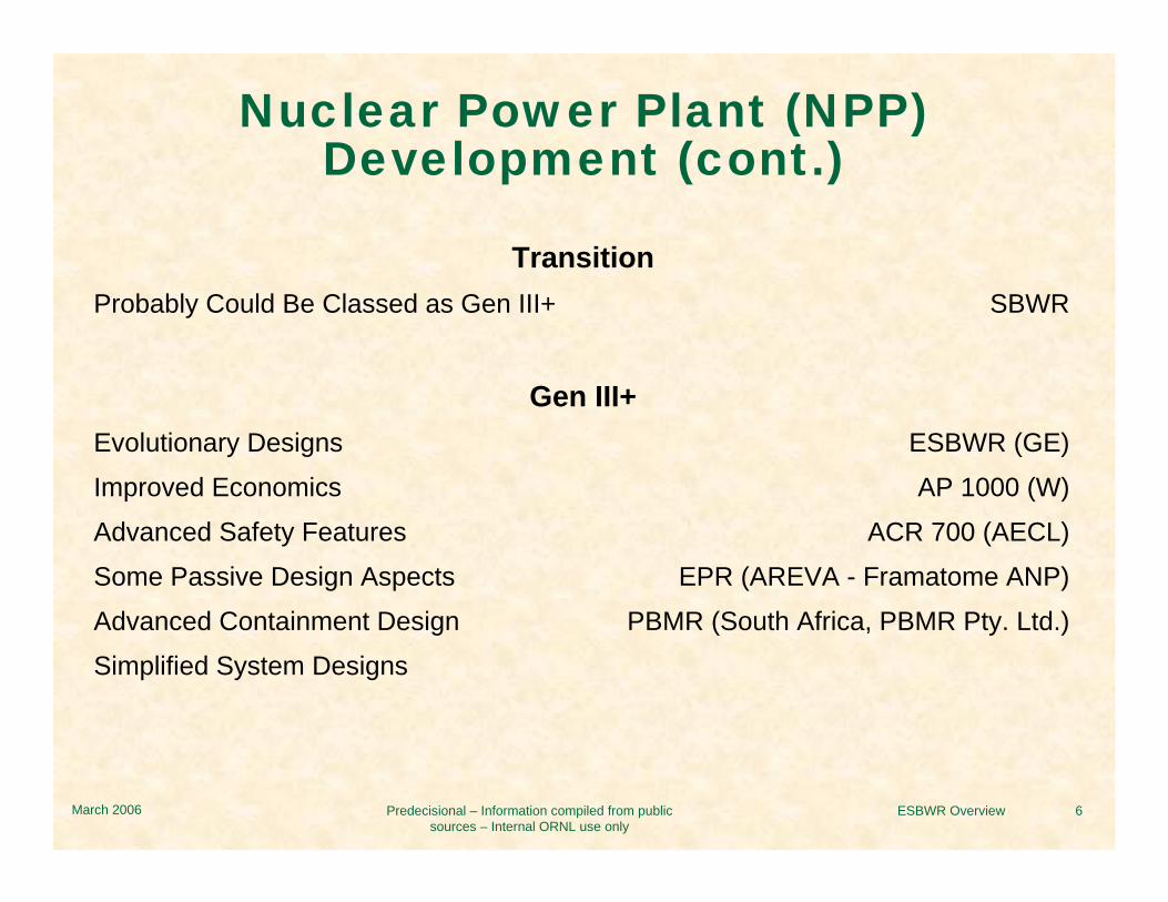
Nuclear Power Plant (NPP) Development (cont.)
TransitionProbably Could Be Classed as Gen III+ SBWR
Gen III+Evolutionary Designs ESBWR (GE)Improved Economics AP 1000 (W)Advanced Safety Features ACR 700 (AECL)Some Passive Design Aspects EPR (AREVA - Framatome ANP)Advanced Containment Design PBMR (South Africa, PBMR Pty. Ltd.)Simplified System Designs

3GE Energy / NuclearSeptember 27, 2005
Oyster Creek
KRBDresden 1
ABWR
Dresden 2
ESBWRSBWR
BWR Evolution

ESBWR OverviewPredecisional – Information compiled from publicsources – Internal ORNL use only
March 2006
BWR Design Progression
BWR 2-6 ABWR SBWR ESBWR− 35 Domestic (U.S.) operating BWRs− 17 International operating BWRs− 2 International (Japan) operating ABWRs− Provide the current status of its design certification process with the NRC.
BWR Product Line 2/3/4− Motor Generator Used for Recirculation System Flow Control− High Pressure Coolant Injection (except early BWR 2s - Nine Mile Point 1 and
Oyster Creek which used Feedwater Coolant Injection)
BWR Product Line 5/6− Flow Control Valves for Recirculation System Control− High Pressure Core Spray
Recirculation Systems− 5 Loops - Nine Mile Point 1 and Oyster Creek− 2 Loops - all others

ESBWR OverviewPredecisional – Information compiled from publicsources – Internal ORNL use only
March 2006
BWR Design Progression (cont.)
Isolation Condenser Systems− Dresden 2 & 3− Nine Mile Point 1− Oyster Creek
Natural Circulation− Humboldt Bay
Containment− Mark 1 (23) BWR 2,3 and older BWR 4s
inverted light bulbdrywell and torususually an inerted atmosphere
− Mark II (8) Newer BWR 4s and BWR 5sfrustum of conecalled “over-under”
− Mark III (4) BWR 6spressure suppression

ESBWR OverviewPredecisional – Information compiled from publicsources – Internal ORNL use only
March 2006
ABWR NPPs
Kashiwazaki Units 6 & 7 Located in Japan
Expected time to fuel load . . . . . . . . . . . . . . . . . . . . . . . . . . . . . . . 39 months
Actual construction time. . . . . . . . . . . . . . . . . . . . . . . . . . . Unit 6 - 61 months
Actual construction time. . . . . . . . . . . . . . . . . . . . . . . . . . . Unit 6 - 61 months
Actual time to fuel load . . . . . . . . . . . . . . . . . . . . . . . . . . Unit 6 - 36.5 months
. . . . . . . . . . . . . . . . . . . . . . . . . . Unit 7 - 38.3 months
Broke ground September 17, 1991
Commercial operation . . . . . . . . . . . . . . . . . . . . . Unit 6 - November 7, 1996
. . . . . . . . . . . . . . . . . . . . . . . . . . Unit 7 - July 2, 1997

ESBWR OverviewPredecisional – Information compiled from publicsources – Internal ORNL use only
March 2006
ABWR NPPs (cont.)
Lungmen Units 1 & 2 Located in Taiwan
Expected construction time . . . . . . . . . . . . . . . . . . . . . . . . . . . . . . 48 months
Delayed up to 2005 at 57% complete
Reactor installed. . . . . . . . . . . . . . . . . . . . . . . . . . . . . . . .Unit 1 - March 2005
Expected operation . . . . . . . . . . . . . . . . . . . . . . . . . . . . . . .Unit 1 - July 2006
. . . . . . . . . . . . . . . . . . . . . . . . . . . . Unit 2 - July 2007

18GE Energy / NuclearSeptember 27, 2005
zero1899Safety system pumps
zero332Safety diesel generator
zero102(large)2(large)Recirculation pumps
4500/15803926/13503900/13603293/1098Power (MWt/GrossMWe)
3E-81E-71E-61E-5Core damage freq./yr
~ 130160150115Safety Bldg Vol (m3/MWe)
27.7/7.121.1/7.121.8/6.421.9/6.4Vessel height/dia. (m)
185/LP
50
3.7
764
BWR/4-Mk I(Browns Ferry 3)
193/LP
54.2
3.7
800
BWR/6-Mk III(Grand Gulf)
269/FM205/FMNumber of CRDs/type
5451Power density (kw/l)
3.03.7Active Fuel Height (m)
1132872Fuel Bundles (number)
ESBWRABWRParameter
Optimized Parameters for ESBWR

17GE Energy / NuclearSeptember 27, 2005
Made non-safety gradeReactor Building Service Water (Safety Grade)And Plant Service Water (Safety Grade)
Replaced pumps with accumulatorsSLC –2 pumps
Replaced with IC heat exchangersRCIC
Eliminated – only 2 non-safety grade dieselsSafety Grade Diesel Generators (3 each)
Non-safety, combined with cleanup systemResidual Heat Removal (3 each)
Utilize passive and stored energyLPFL (3 each)
Eliminated need for ECCS pumpsHPCF System (2 each)
EliminatedRecirculation System + support systems
ESBWRABWR
What’s different about ESBWR

- 94 -
BWR Containment Comparison
3042399424450LOCA Pressure (psig)
40554515456250Design Pressure (psig)
0.430.30.51.60.50.42.5Drywell and wetwell volume (ft3 X 106)
YesYesYesYesYesYesNoPressure Suppression
ESBWRSBWRABWRMark IIIMark IIMark IDryCharacteristic
ESBWR Overview 7Predecisional – Information compiled from public sources – Internal ORNL use only
March 2006
ESBWR
Plant Licensing Status

ESBWR Overview 7Predecisional – Information compiled from public sources – Internal ORNL use only
March 2006
ESBWR
Design Certification• Accepted for docketing by the NRC in December 2005.
• Final Design Approval (FDA) is expected in December 2009.
• Design Certification expected in December 2010.
Utility Activities• The consortium, NuStart, is expected to apply for a construction/operating
license (COL) for an ESBWR for Entergy Nuclear at its Grand Gulf Site in late 2007 or early 2008.
• Dominion will be ready to apply for a COL for an ESBWR at its North Anna Site in September 2007.
• Entergy Nuclear will apply for a COL for an ESBWR at its River Bend Site in the first half of 2008.

ESBWR Overview 8Predecisional – Information compiled from public sources – Internal ORNL use only
March 2006
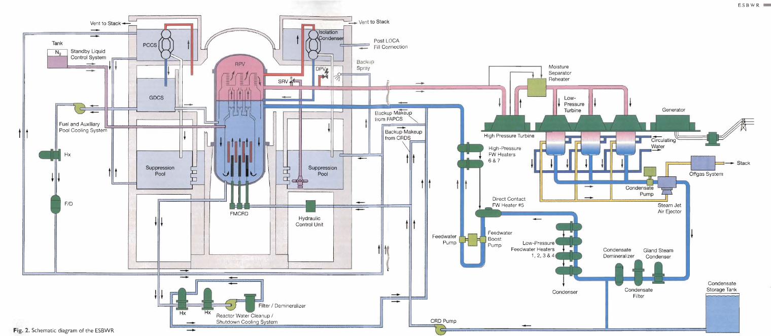
ESBWR
Plant Overview

ar02-19
Safety Systems Inside Containment Envelope
All Pipes/Valves Inside Containment
High Elevation Gravity Drain Pools
Raised Suppression Pool
Decay Heat HX’sAbove Drywell

ESBWR Overview 9Predecisional – Information compiled from public sources – Internal ORNL use only
March 2006
ESBWR
Core and Vessel Design

19GE Energy / NuclearSeptember 27, 2005

- 9 -
Water Rods
Lower Tie PlateDebris Filter
Part LengthFuel Rods
Interactive ChannelESBWR Fuel Assembly
• Same cross-sectionaldimensions as ABWR
• Active Fuel Length:ABWR = 144 inchesESBWR = 120 inches
Upper Tie Plate
Zircaloy FerruleSpacers

Page 3Performance PS0206-1
ESBWR Normal Operation
• No recirculation pumps – total reliance on natural circulation
• Significant natural circulation flow exists in all BWR’s
• For a given core power, there is a corresponding natural circulation flow
• ESBWR uses enhanced design features to increase the flow compared to standard BWR’s

ESBWR Overview 10Predecisional – Information compiled from public sources – Internal ORNL use only
March 2006
ESBWR
Important Systems

ESBWR Overview 11Predecisional – Information compiled from public sources – Internal ORNL use only
March 2006
ESBWR
Control Rod Drive System (CRDS)

- 18 -
Control Rod Drive SystemNew features added
CORE
REACTORVESSEL
SUCTIONFILTERS
CONDENSATESTORAGETANK
FROM CONDENSATEAND FEEDWATER
CRDPUMPS
TEST LINE
MIN FLOWLINE
FW
RWCU/SDC
FE FE
INJECTIONVALVES
ACCUMULATOR
CRDs
HCUsCHARGINGHEADER
FERO
DRIVEWATERFILTERS
RWCU/SDCPUMPS PURGE WATER
CONTROL VALVES
PURGEHEADER
DRYWELL
Second pump starts:Low header press.Low water level 2
Bypass valves open:Low water level 2
*Valves close:Low water level 2
* *
Valves open:Low water level 2

ESBWR Overview 12Predecisional – Information compiled from public sources – Internal ORNL use only
March 2006
ESBWR
Isolation Condenser System (ICS)

- 32 -
FOUR TRAINS OF• 30 MWt HEAT CAPACITY EACH
CORE
REACTORVESSEL
DRYER
25A
RO RO
RO
20A
MO
MO
MO
NMO
350A
DPV
STUBLINE
SUPPRESSIONPOOL
MAINSTEAMLINE
200A 200A
200A20A
200A
MO
MO
NO
ISOLATION CONDENSER
IC/PCCPOOL
300A
ATMOSPHERICVENT
TRAIN A SHOWNNMO
MO
DRYWELL
ESBWR Isolation Condenser System - Schematic Diagram
LOOPS A, B, C ONLY
LOOPS B, C, D ONLY

- 30 -
Isolation CondenserSimplified

ESBWR Overview 13Predecisional – Information compiled from public sources – Internal ORNL use only
March 2006
ESBWR
Standby Liquid Control System (SLCS)

25 /GE /
April 5, 2005
Standby Liquid Control System

ESBWR Overview 14Predecisional – Information compiled from public sources – Internal ORNL use only
March 2006
ESBWR
Reactor Water Cleanup (RWCU) / Shutdown Cooling (SDC) System

6 /GE /
April 5, 2005
Reactor Water Cleanup (RWCU)

ESBWR Overview 15Predecisional – Information compiled from public sources – Internal ORNL use only
March 2006
ESBWR
Safety Systems

ESBWR Overview 16Predecisional – Information compiled from public sources – Internal ORNL use only
March 2006
ESBWR
Gravity-Driven Cooling System (GDCS)

- 37 -
ESBWR Gravity-Driven Cooling System - Schematic Diagram
CORE
DIVISION A SHOWN
TYP DIV B, C, D
REACTORVESSEL
GDCSPOOL
WW/GDCS POOLVENTPIPE
TEMPSTRAINER
GDCSSUMP
DRYWELL
TM TM
TM
TM
A 150A
150A
150A
INJECTIONLINE
SUPPRESSIONPOOL
WETWELLAIRSPACE
BIASED-OPENSWING-CHECKVALVE
EQUALIZINGLINE
A
INJECTIONSQUIB-VALVE
200A
(UPPER DRYWELLANNULUS)
(OMITTEDFROMDIV. D)
SUPPRESSIONPOOL
WETWELLAIRSPACE
DELUGELINE
= TORQUE MOTOR (MAGNETIC-COUPLED)
= WETWELL AIRSPACEWW

ESBWR Overview 17Predecisional – Information compiled from public sources – Internal ORNL use only
March 2006
ESBWR
Passive Containment CoolingSystem (PCCS)

6 /GE /
April 5, 2005
Passive Containment Cooling System

- 40 -
Passive Containment CoolingSimplified

ESBWR Overview 18Predecisional – Information compiled from public sources – Internal ORNL use only
March 2006
ESBWR
Depressurization

15 /GE /
April 5, 2005
MSIV, SRV and DPV Arrangement

ESBWR Overview 19Predecisional – Information compiled from public sources – Internal ORNL use only
March 2006
ESBWR
Containment Design

- 60 -
ESBWR Containment System - Schematic Diagram
LEAKDETECTION
(TYP OF 10)
Burst DiaphragmPrimary COPS(opens at severeaccident pressure)
Containment BoundaryDesign Basis Accident
Additional VolumeAvailable ForPrimary COPS
WetwellAirspace
PCCSHx’s
(Typ of 4)
DW/WW LOCAVerticalVentpipes(Typ of 10)
ReactorVessel
CoreSuppression
PoolGDCS Injection Line
Suction End
GDCS Pool Sump(Typ of 4)
Bolted AccessHatch
WW/GDCS PoolVentpipe(Typ of 3)
WW/GDCS Pool(Typ of 3)
UpperDrywell
VB
Vacuum Breaker(Typ of 3)
Spill OverflowLines
EquipmentHatch
Corium splash Shield
Personnel Hatch
UndervesselWork Platform
EquipmentHatch

ESBWR Overview 20Predecisional – Information compiled from public sources – Internal ORNL use only
March 2006
ESBWR
Additional Systems

ESBWR Overview 21Predecisional – Information compiled from public sources – Internal ORNL use only
March 2006
ESBWR
Power Conversion System (PCS)

Page 5September 27, 2005

ESBWR Overview 22Predecisional – Information compiled from public sources – Internal ORNL use only
March 2006
ESBWR
Instrumentation and Control (I&C)

30 /GE /
October 3, 2005
Summary of ESBWR I&C Characteristics
• ESBWR's digital I&C design is based on the same digital I&C framework, design, and hardware/software platforms of ABWR. The ABWR digital I&C design has been in operation and in construction (with hardware/software infabrication/testing). – proven system and hardware/software designs.
• Automation implemented same as ABWR• Minimized hardwired cables same as ABWR• Digital Remote Shutdown System capable of full plant control and enhances EOP
utilization• Enhanced “diverse protection and actuation” capability in compliance to BTP
HICB - 19• Fixed in-core gamma thermometer AFIP to replace the TIP system
– simplified operation and reduced personnel radiation dosage.- eliminated TIP containment penetrations
• The ESBWR I&C design will comply with updated or newly developed regulatory requirements such as BTP-14, BTP-19, as well as RG1.152.

ESBWR Overview 23Predecisional – Information compiled from public sources – Internal ORNL use only
March 2006
ESBWR
Electrical Distribution

Page 19September 27, 2005
Standby On-site AC Power Supply
• Consists of two 15 MVA independent diesels coupled to 6.9 kV AC generators, the DG auxiliary systems, fuel storage and transfer systems and associated local instruments and controls.
• Each DG supplies non-safety AC power to it’s associated PIP busses on loss of voltage for plant investment protection.
• On PIP bus undervoltage the DG starts, accelerates with in 1 minute. • Major loads are tripped from the 6.9 kV PIP busses. • DG will connect to the PIP busses when incoming preferred and alternate
preferred source breakers have been tripped.• Large motor loads are then reapplied sequentially and automatically after
DG power source breaker closes.• The DG is capable of being fully loaded within 600 seconds.• DG operation is not required to ensure nuclear safety – only investment
protection

ESBWR Overview 24Predecisional – Information compiled from public sources – Internal ORNL use only
March 2006
ESBWR
Accident Analysis

ESBWR Overview 25Predecisional – Information compiled from public sources – Internal ORNL use only
March 2006
ESBWR
Probabilistic Risk Assessment(PRA)

3GE Energy / NuclearSeptember 29, 2005
Document Relationships
ESBWR PRA
NEDC-33201P ESBWR DCD
Chapter 19
Scope
Methods
Goals
DesignRequirements
SAMDA

36GE Energy / NuclearSeptember 29, 2005
Breakdown By Initiating Event
Large Steam LOCA3.2%
Transient0.4%
IORV0.4%
Medium Liquid LOCA0.9%
Loss of Feedwater38.0% Loss of Power
56.8%
RWCU Line Break0.1%
Feedwater Line Break0.1%
Loss of Condenser0.1%

37GE Energy / NuclearSeptember 29, 2005
Breakdown By Accident ClassContainment
Overpressure8%
Low Pressure Core Damage
90%
High Pressure Core Damage
1%
ATWS1%
Containment Bypass<< 1%

ESBWR Overview 26Predecisional – Information compiled from public sources – Internal ORNL use only
March 2006
ESBWR
Design Control Document (DCD) Accident Analyses

50GE Energy / NuclearSeptember 29, 2005
ESBWR Severe Accident Treatment – Work Structure
Analysis of CDF-DS
parameters
Characterization of Safety Systems
Risk-SignificantCore MeltScenarios
CDF-Dominant Sequences (DS)
Source Terms Level 3
Threats to Containment Integrity
Conditional Containment Failure Probability (CCFP)
Containment Strength
Applications of Risk-Oriented Accident Analysis
Methodology (ROAAM)(DCH, FCI, CCI, H2, Bypass, etc…)
Plant Design
PSALevel 1
SAT
CRSS
ContainmentEvent Trees
(CET)
MAAP-ESBWRCalculations of
Accident Progression
Containment and Safety
Systems
Plant Damage State