new gas detection systems, air monitors, detectors | teledyne - … · 2020. 2. 12. · the fixed...
TRANSCRIPT
1
The Fixed Gas Detection Experts
TECHNICAL MANUAL OLCT IR
INFRARED DETECTOR FOR FLAMMABLE GASES OR
CO2
Part Number : NPOIRGB
Revision : G.0
2 User manual
Copyright April 2016 by Oldham S.A.S.
All rights reserved. No reproduction of all or part of this document, in any
form, is permitted without the written consent of Oldham S.A.S.
All of the information that is provided in this document is accurate to the
best of our knowledge.
As a result of continuous research and development, the specifications of
this product may be changed without prior notice.
Oldham S.A.S.
Rue Orfila
Z.I. Est – CS 20417
F–62027 ARRAS Cedex
Tel.: +33 (0)3 21 60 80 80
Fax: +33 (0)3 21 60 80 00
3
GAS DETECTION
Thank you for purchasing an OLDHAM instrument. We appreciate your business.
We trust that our commitment to the technical excellence of our products will ensure your complete
satisfaction.
Please read the following document carefully.
L I M I T A T I O N O F L I A B I L I T Y
* OLDHAM will not be liable under any circumstances for material losses, personal injury or death resulting in whole
or in part from the inappropriate use of this equipment, the installation or storage of this equipment not in
conformance with the instructions and warnings presented in this manual and/or not in conformance with current
standards and regulations.
* OLDHAM neither condones nor authorizes any other company, individual or legal entity to make any claims as to the
liability of OLDHAM, even if said company, individual or legal entity is directly involved in the sale of OLDHAM
products.
* In no event will OLDHAM be liable for any direct or indirect damage including those resulting from the sale and the
use of its products IF THOSE PRODUCTS WERE NOT SPECIFIED AND SELECTED BY OLDHAM FOR
SUCH USE.
O W N E R S H I P C L A U S E S
* The images, blueprints, specifications and information contained in this document belong to OLDHAM.
* This information may not be physically, electronically or otherwise reproduced, copied, disclosed, or translated, either
in part or in whole, or used in the manufacturing or sale of OLDHAM equipment, nor for any other reason without
prior permission from OLDHAM.
W A R N I N G S
* This document is not contractual. On behalf of its clients, OLDHAM reserves the right to modify the technical
characteristics of its equipment without notice to improve product performance.
* CAREFULLY READ THIS DOCUMENT BEFORE USING THE PRODUCT: this document should be
carefully read by any individual who has or who will have the authority to use, maintain or repair this equipment.
* Any and all warrantees and performance claims will only be valid if the equipment is operated, maintained and
repaired in accordance with OLDHAM directives, by OLDHAM personnel or by personnel appointed by
OLDHAM.
W A R R A N T Y
* Five-year return to factory warranty under normal operating conditions on parts and labor; consumable materials
excluded (sensors, filters, etc.).

4 User manual
D I S P O S A L
For the preservation, protection and improvement of environmental quality, and for the protection of human health and
the prudent and rational utilization of natural resources, the OLCT IR must be disposed of separately from electronic
equipment and cannot be disposed of with normal household waste. The user therefore has an obligation to separate the
OLCT IR from other waste to ensure that it is recycled safely for the environment.For further details on existing
collection sites, contact the local administration or seller of the product.
Contents 1
CONTENTS Figure 1 ..................................................................................................................................................................... 0
Figure 2 ..................................................................................................................................................................... 1
Figure 3 ..................................................................................................................................................................... 2
Figure 4 ..................................................................................................................................................................... 3
Figure 5 ..................................................................................................................................................................... 4
1. INTRODUCTION ........................................................................................................................................... 6
2. TECHNICAL SPECIFICATIONS(1)
..................................................................................................................... 8
2.1 INTERFERENCE OF COMMON GASES ON OLCT IR (CH4 AND HC) .............................................................................. 9
3. INSTALLATION ........................................................................................................................................... 12
4. START UP ................................................................................................................................................... 12
5. MAINTENANCE .......................................................................................................................................... 14
5.1 CORRECTIVE MAINTENANCE............................................................................................................................. 14 5.2 PERIODIC MAINTENANCE ................................................................................................................................ 14
6. LIST OF ACCESSORIES ................................................................................................................................. 18
7. SPECIAL INSTRUCTIONS FOR USE IN ATEX EXPLOSIVE ATMOSPHERES AND FOR FUNCTIONAL SAFETY ...... 20
7.1 USE IN ATEX EXPLOSIVE ATMOSPHERES ............................................................................................................. 20 7.2 FUNCTIONAL SAFETY ...................................................................................................................................... 21
8. MARKING: ................................................................................................................................................. 22
9. MANUFACTURER’S DECLARATION OF CONFORMITY ................................................................................. 24

2 User Manuel

0 User Manual
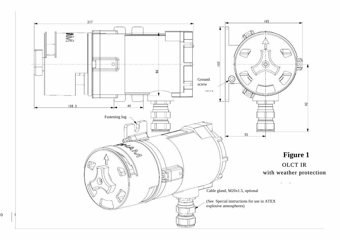
OLCT IR
Avec coiffe anti-
projection
OLCT IR
with weather protection
Ground
screw
(See Special instructions for use in ATEX
explosive atmospheres)
Cable gland, M20x1.5, optional
Fastening lug
Figure 1
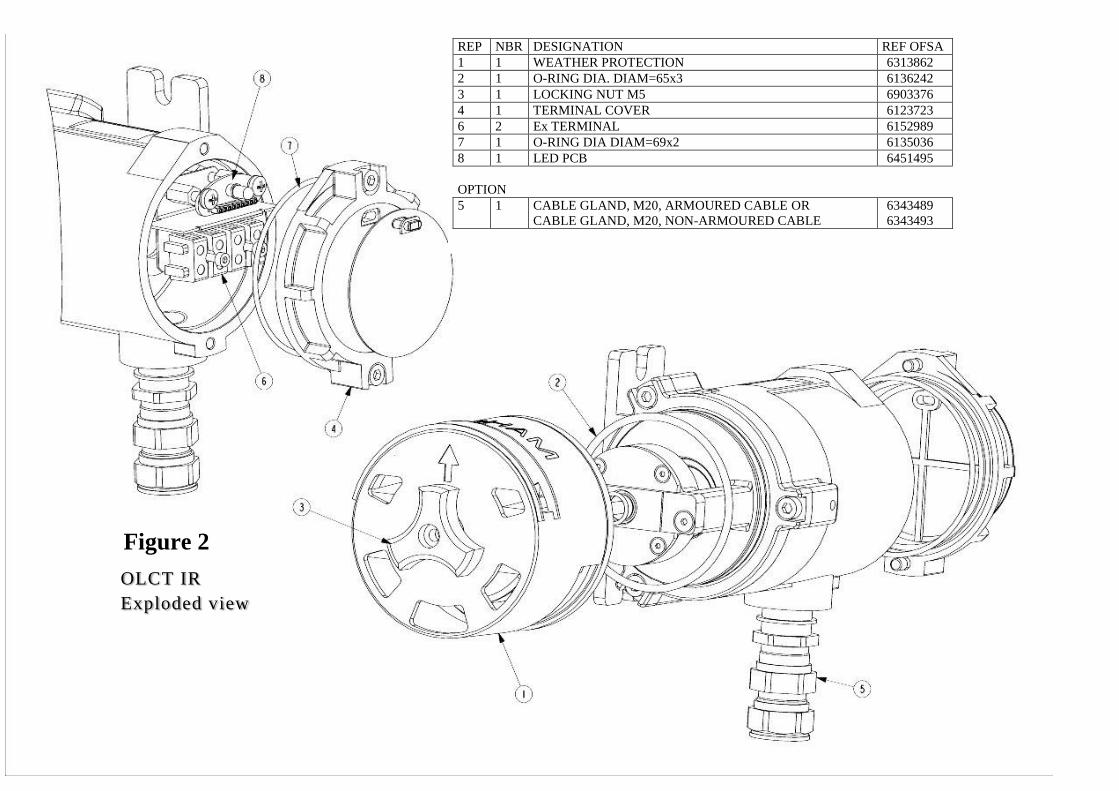
REP NBR DESIGNATION REF OFSA
1 1 WEATHER PROTECTION 6313862
2 1 O-RING DIA. DIAM=65x3 6136242
3 1 LOCKING NUT M5 6903376
4 1 TERMINAL COVER 6123723
6 2 Ex TERMINAL 6152989
7 1 O-RING DIA DIAM=69x2 6135036
8 1 LED PCB 6451495
OPTION
5 1 CABLE GLAND, M20, ARMOURED CABLE OR
CABLE GLAND, M20, NON-ARMOURED CABLE
6343489
6343493
OLCT IR
Exploded view
Figure 2

2 User Manual
OLCT IR
Terminal block
Iout
0V
+24VDC
Ser
the electric wires will be equipped
with a crimped end
Connection
Iout Output signal in mA (terminal 1 of OLDHAM
central units)
0V Power supply 0 V (terminal 2 of OLDHAM
central units)
+24VDC Power supply + (terminal 3 of OLDHAM
central units)
Ser = service (do not use)
LED
Magnetic receiver
Cable gland M25 x 1.5, optional
(See: Special instructions for use in
ATEX explosive atmospheres)
Figure 3

/M25
OLCT IR
with by-pass adaptor
(calibration cup)
GAS INLET AND OUTLET
BY-PASS ADAPTOR
Ground
screw
Fastening lug
Cable gland, M20
Figure 4
4 User Manual
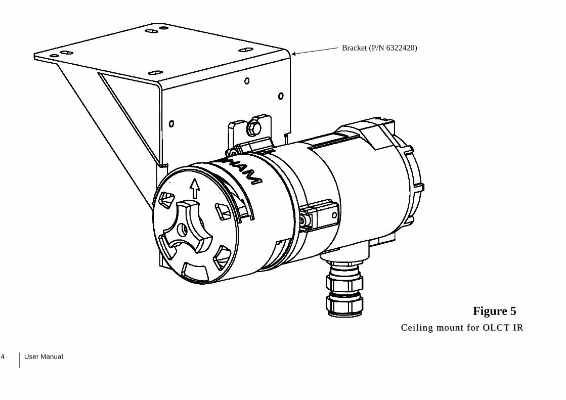
Bracket (P/N 6322420)
Ceiling mount for OLCT IR
Figure 5

6 User Manual
1. INTRODUCTION
The OLCT IR gas detector is designed to monitor flammable gases or CO2 concentrations in the ambient air.
The infrared technology used by the OLCT IR guarantees extreme detection accuracy.
Powered with 24 Vdc, the OLCT IR provides a standard 4-20 mA analog output which is proportional to the
measured concentration of gas. It features a non-intrusive calibration that enables calibration in hazardous area without
declassifying the zone.
The OLCT IR detector can be used in gas and dust explosive atmospheres and meets all of the essential
requirements of the ATEX 94/9/EC European Directive and following European EN and international IEC standards:
- EN 60079-0:2012 IEC 60079-0 (ed.6):2011
- EN 60079-1:2007 IEC 60079-1 (ed.6):2007
- EN 60079-7:2007 IEC 60079-7 (ed.4):2006
- EN 60079-11:2012 IEC 60079-11 (ed.6):2011
- EN 60079-31-2014 IEC 60079-31 (ed.2):2013
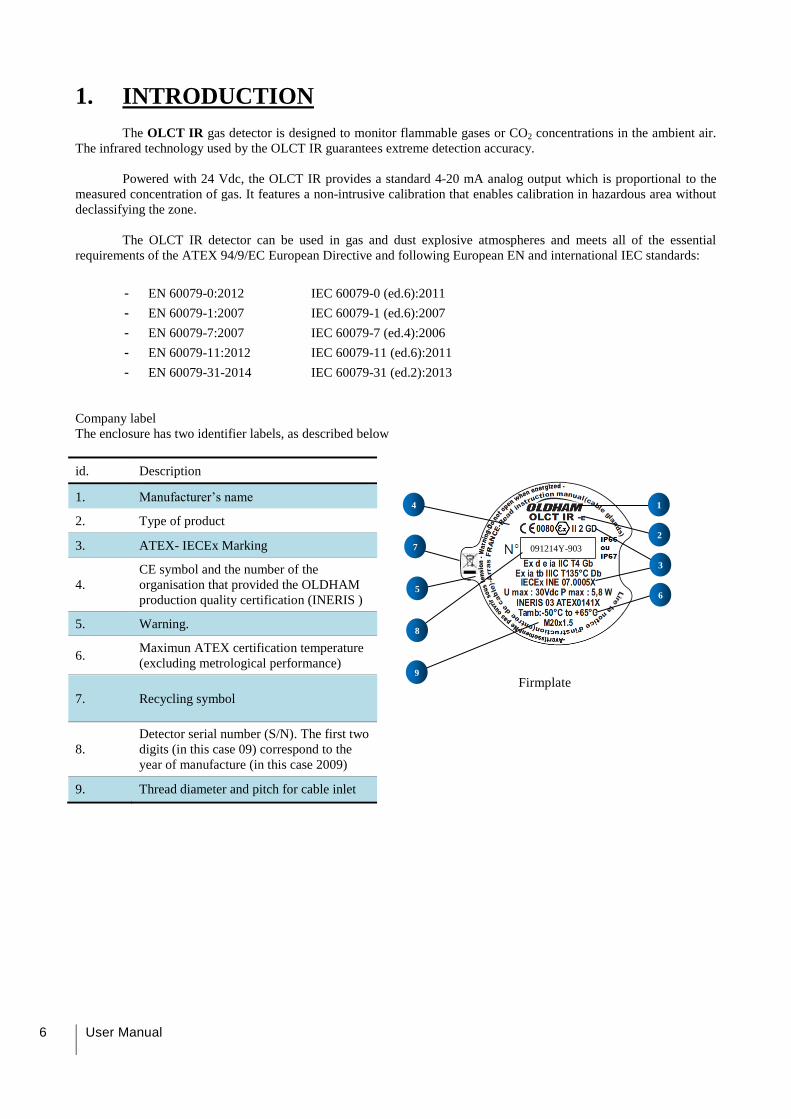
Company label
The enclosure has two identifier labels, as described below
id. Description
Firmplate
1. Manufacturer’s name
2. Type of product
3. ATEX- IECEx Marking
4.
CE symbol and the number of the
organisation that provided the OLDHAM
production quality certification (INERIS )
5. Warning.
6. Maximun ATEX certification temperature
(excluding metrological performance)
7. Recycling symbol
8.
Detector serial number (S/N). The first two
digits (in this case 09) correspond to the
year of manufacture (in this case 2009)
9. Thread diameter and pitch for cable inlet
091214Y-903
3
7
4
5
8
1
2
6
9
1 - Introduction 7
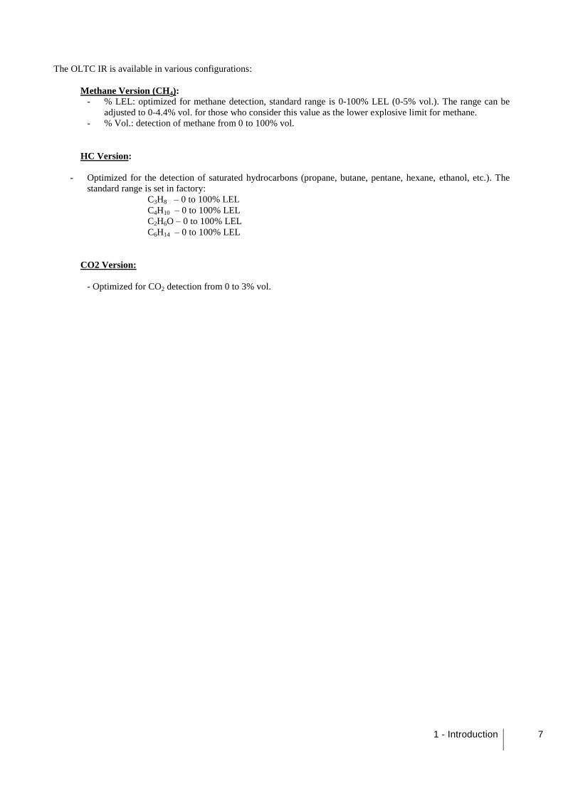
The OLTC IR is available in various configurations:
Methane Version (CH4): - % LEL: optimized for methane detection, standard range is 0-100% LEL (0-5% vol.). The range can be
adjusted to 0-4.4% vol. for those who consider this value as the lower explosive limit for methane.
- % Vol.: detection of methane from 0 to 100% vol.
HC Version:
- Optimized for the detection of saturated hydrocarbons (propane, butane, pentane, hexane, ethanol, etc.). The
standard range is set in factory:
C3H8 – 0 to 100% LEL
C4H10 – 0 to 100% LEL
C2H6O – 0 to 100% LEL
C6H14 – 0 to 100% LEL
CO2 Version:
- Optimized for CO2 detection from 0 to 3% vol.
8 User Manual
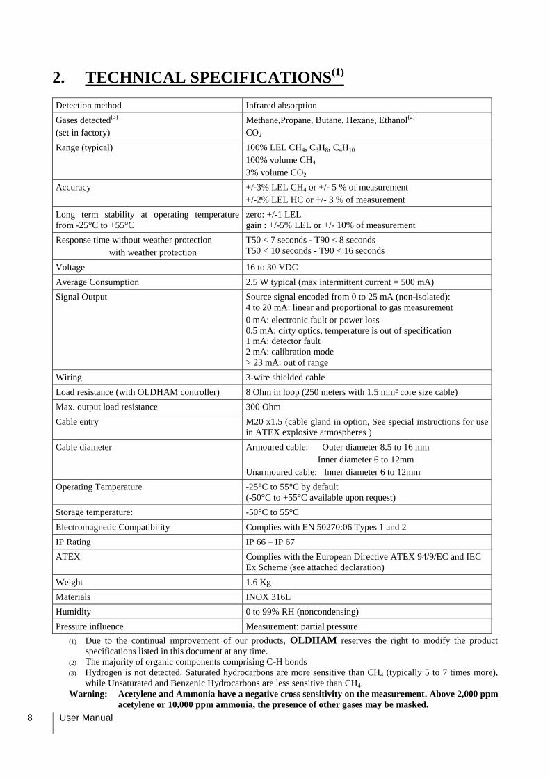
2. TECHNICAL SPECIFICATIONS(1)
Detection method Infrared absorption
Gases detected(3)
(set in factory)
Methane,Propane, Butane, Hexane, Ethanol(2)
CO2
Range (typical) 100% LEL CH4, C3H8, C4H10
100% volume CH4
3% volume CO2
Accuracy +/-3% LEL CH4 or +/- 5 % of measurement
+/-2% LEL HC or +/- 3 % of measurement
Long term stability at operating temperature
from -25°C to +55°C
zero: +/-1 LEL
gain : +/-5% LEL or +/- 10% of measurement
Response time without weather protection
with weather protection
T50 < 7 seconds - T90 < 8 seconds
T50 < 10 seconds - T90 < 16 seconds
Voltage 16 to 30 VDC
Average Consumption 2.5 W typical (max intermittent current = 500 mA)
Signal Output Source signal encoded from 0 to 25 mA (non-isolated):
4 to 20 mA: linear and proportional to gas measurement
0 mA: electronic fault or power loss
0.5 mA: dirty optics, temperature is out of specification
1 mA: detector fault
2 mA: calibration mode
> 23 mA: out of range
Wiring 3-wire shielded cable
Load resistance (with OLDHAM controller) 8 Ohm in loop (250 meters with 1.5 mm² core size cable)
Max. output load resistance 300 Ohm
Cable entry M20 x1.5 (cable gland in option, See special instructions for use
in ATEX explosive atmospheres )
Cable diameter Armoured cable: Outer diameter 8.5 to 16 mm
Inner diameter 6 to 12mm
Unarmoured cable: Inner diameter 6 to 12mm
Operating Temperature -25°C to 55°C by default
(-50°C to +55°C available upon request)
Storage temperature: -50°C to 55°C
Electromagnetic Compatibility Complies with EN 50270:06 Types 1 and 2
IP Rating IP 66 – IP 67
ATEX Complies with the European Directive ATEX 94/9/EC and IEC
Ex Scheme (see attached declaration)
Weight 1.6 Kg
Materials INOX 316L
Humidity 0 to 99% RH (noncondensing)
Pressure influence Measurement: partial pressure
(1) Due to the continual improvement of our products, OLDHAM reserves the right to modify the product
specifications listed in this document at any time.
(2) The majority of organic components comprising C-H bonds
(3) Hydrogen is not detected. Saturated hydrocarbons are more sensitive than CH4 (typically 5 to 7 times more),
while Unsaturated and Benzenic Hydrocarbons are less sensitive than CH4.
Warning: Acetylene and Ammonia have a negative cross sensitivity on the measurement. Above 2,000 ppm
acetylene or 10,000 ppm ammonia, the presence of other gases may be masked.
2 – Technical specifications 9
OLCTIR CH4 calibré CH4 : Interférence des principaux alcanes & alcools
0,0
10,0
20,0
30,0
40,0
50,0
60,0
70,0
80,0
90,0
100,0
0,0 10,0 20,0 30,0 40,0 50,0 60,0 70,0 80,0 90,0 100,0
Conc [% LEL]
Méthane CH4 Propane C3H8 Butane C4H10 Hexane C6H14 Nonane C9H20 Cy clohexane C6H10 Méthanol CH3OH Ethanol C2H6O
% LEL CH4
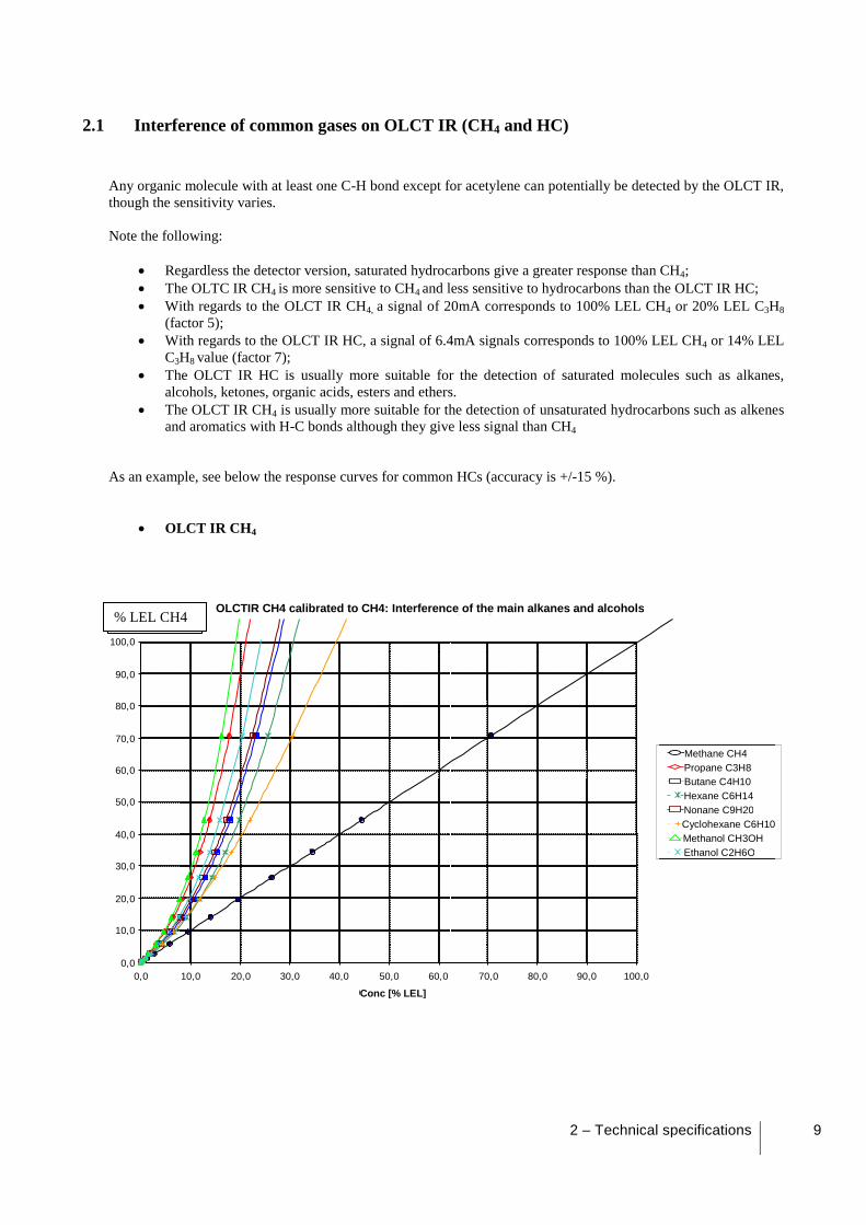
2.1 Interference of common gases on OLCT IR (CH4 and HC)
Any organic molecule with at least one C-H bond except for acetylene can potentially be detected by the OLCT IR,
though the sensitivity varies.
Note the following:
Regardless the detector version, saturated hydrocarbons give a greater response than CH4;
The OLTC IR CH4 is more sensitive to CH4 and less sensitive to hydrocarbons than the OLCT IR HC;
With regards to the OLCT IR CH4, a signal of 20mA corresponds to 100% LEL CH4 or 20% LEL C3H8
(factor 5);
With regards to the OLCT IR HC, a signal of 6.4mA signals corresponds to 100% LEL CH4 or 14% LEL
C3H8 value (factor 7);
The OLCT IR HC is usually more suitable for the detection of saturated molecules such as alkanes,
alcohols, ketones, organic acids, esters and ethers.
The OLCT IR CH4 is usually more suitable for the detection of unsaturated hydrocarbons such as alkenes
and aromatics with H-C bonds although they give less signal than CH4
As an example, see below the response curves for common HCs (accuracy is +/-15 %).
OLCT IR CH4
OLCTIR CH4 calibrated to CH4: Interference of the main alkanes and alcohols
Conc [% LEL]
Methane CH4 Propane C3H8 Butane C4H10 Hexane C6H14 Nonane C9H20 Cyclohexane C6H10 Methanol CH3OH Ethanol C2H6O
% LEL CH4
10 User Manual
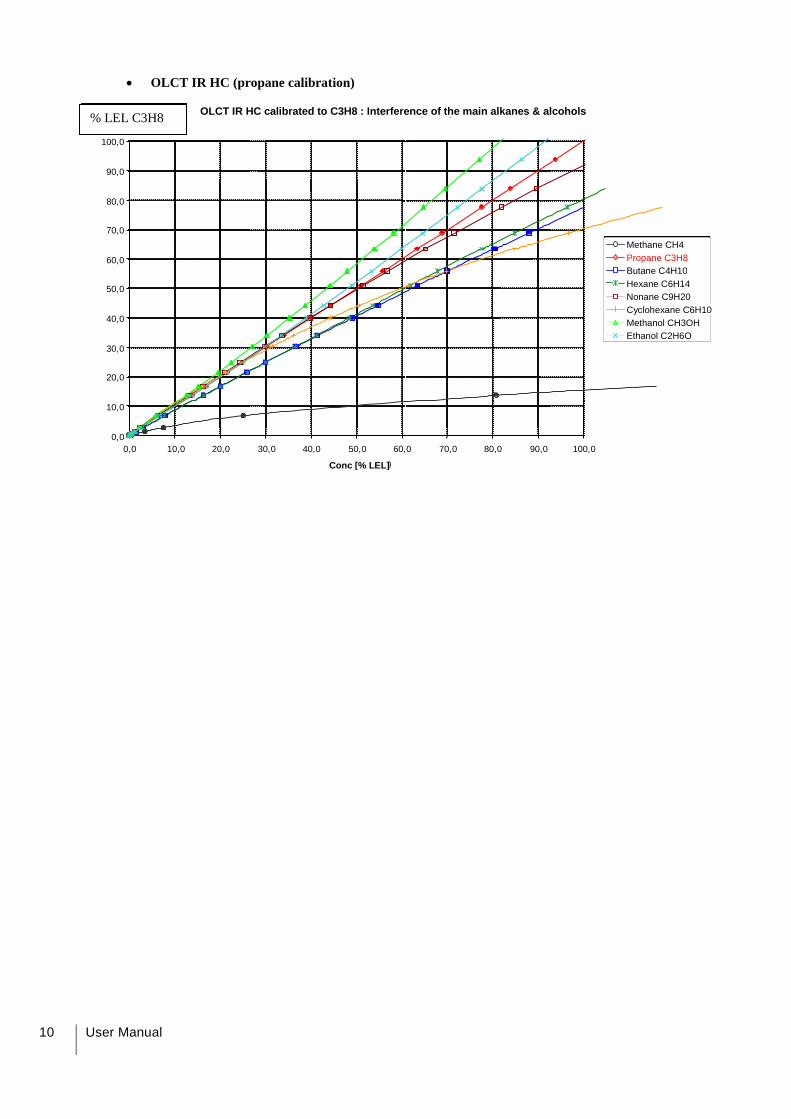
OLCT IR HC (propane calibration)
OLCT IR HC calibré C3H8 : Interférence des principaux alcanes & alcools
0,0
10,0
20,0
30,0
40,0
50,0
60,0
70,0
80,0
90,0
100,0
0,0 10,0 20,0 30,0 40,0 50,0 60,0 70,0 80,0 90,0 100,0
Conc [% LEL)
Méthane CH4 Propane C3H8 Butane C4H10 Hexane C6H14 Nonane C9H20 Cy clohexane C6H10 Méthanol CH3OH Ethanol C2H6O
% LEL C3H8 OLCT IR HC calibrated to C3H8 : Interference of the main alkanes & alcohols
Conc [% LEL]
Methane CH4 Propane C3H8 Butane C4H10 Hexane C6H14 Nonane C9H20 Cyclohexane C6H10 Methanol CH3OH Ethanol C2H6O
% LEL C3H8

2 – Technical specifications 11
12 User Manual
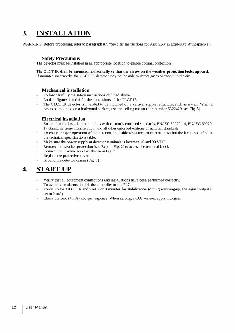
3. INSTALLATION
WARNING: Before proceeding refer to paragraph #7, “Specific Instructions for Assembly in Explosive Atmospheres”.
Safety Precautions
The detector must be installed in an appropriate location to enable optimal protection.
The OLCT IR shall be mounted horizontally so that the arrow on the weather protection looks upward.
If mounted incorrectly, the OLCT IR detector may not be able to detect gases or vapors in the air.
Mechanical installation
- Follow carefully the safety instructions outlined above
- Look at figures 1 and 4 for the dimensions of the OLCT IR
- The OLCT IR detector is intended to be mounted on a vertical support structure, such as a wall. When it
has to be mounted on a horizontal surface, use the ceiling mount (part number 6322420, see Fig. 5).
Electrical installation
- Ensure that the installation complies with currently enforced standards, EN/IEC 60079-14, EN/IEC 60079-
17 standards, zone classification, and all other enforced editions or national standards.
- To ensure proper operation of the detector, the cable resistance must remain within the limits specified in
the technical specifications table.
- Make sure the power supply at detector terminals is between 16 and 30 VDC
- Remove the weather protection (see Rep. 4, Fig. 2) to access the terminal block
- Connect the 3 active wires as shown in Fig. 3
- Replace the protective cover
- Ground the detector casing (Fig. 1)
4. START UP
- Verify that all equipment connections and installations have been performed correctly.
- To avoid false alarms, inhibit the controller or the PLC.
- Power up the OLCT IR and wait 2 or 3 minutes for stabilization (during warming-up, the signal output is
set to 2 mA)
- Check the zero (4 mA) and gas response. When zeroing a CO2 version, apply nitrogen.

4 – Start up 13
14 User Manual
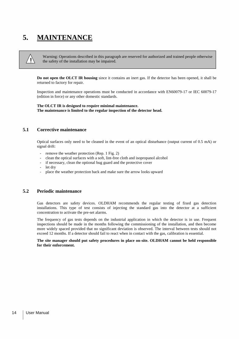
5. MAINTENANCE
Warning: Operations described in this paragraph are reserved for authorized and trained people otherwise
the safety of the installation may be impaired.
Do not open the OLCT IR housing since it contains an inert gas. If the detector has been opened, it shall be
returned to factory for repair.
Inspection and maintenance operations must be conducted in accordance with EN60079-17 or IEC 60079-17
(edition in force) or any other domestic standards.
The OLCT IR is designed to require minimal maintenance.
The maintenance is limited to the regular inspection of the detector head.
5.1 Corrective maintenance
Optical surfaces only need to be cleaned in the event of an optical disturbance (output current of 0.5 mA) or
signal drift:
remove the weather protection (Rep. 1 Fig. 2)
clean the optical surfaces with a soft, lint-free cloth and isopropanol alcohol
if necessary, clean the optional bug guard and the protective cover
let dry
place the weather protection back and make sure the arrow looks upward
5.2 Periodic maintenance
Gas detectors are safety devices. OLDHAM recommends the regular testing of fixed gas detection
installations. This type of test consists of injecting the standard gas into the detector at a sufficient
concentration to activate the pre-set alarms.
The frequency of gas tests depends on the industrial application in which the detector is in use. Frequent
inspections should be made in the months following the commissioning of the installation, and then become
more widely spaced provided that no significant deviation is observed. The interval between tests should not
exceed 12 months. If a detector should fail to react when in contact with the gas, calibration is essential.
The site manager should put safety procedures in place on-site. OLDHAM cannot be held responsible
for their enforcement.
!
5 – Maintenance 15
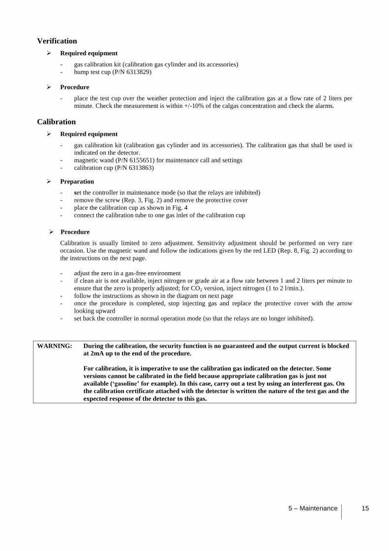
Verification
Required equipment
- gas calibration kit (calibration gas cylinder and its accessories)
- bump test cup (P/N 6313829)
Procedure
- place the test cup over the weather protection and inject the calibration gas at a flow rate of 2 liters per
minute. Check the measurement is within +/-10% of the calgas concentration and check the alarms.
Calibration
Required equipment
- gas calibration kit (calibration gas cylinder and its accessories). The calibration gas that shall be used is
indicated on the detector.
- magnetic wand (P/N 6155651) for maintenance call and settings
- calibration cup (P/N 6313863)
Preparation
- set the controller in maintenance mode (so that the relays are inhibited)
- remove the screw (Rep. 3, Fig. 2) and remove the protective cover
- place the calibration cup as shown in Fig. 4
- connect the calibration tube to one gas inlet of the calibration cup
Procedure
Calibration is usually limited to zero adjustment. Sensitivity adjustment should be performed on very rare
occasion. Use the magnetic wand and follow the indications given by the red LED (Rep. 8, Fig. 2) according to
the instructions on the next page.
- adjust the zero in a gas-free environment
- if clean air is not available, inject nitrogen or grade air at a flow rate between 1 and 2 liters per minute to
ensure that the zero is properly adjusted; for CO2 version, inject nitrogen (1 to 2 l/min.).
- follow the instructions as shown in the diagram on next page
- once the procedure is completed, stop injecting gas and replace the protective cover with the arrow
looking upward
- set back the controller in normal operation mode (so that the relays are no longer inhibited).
WARNING: During the calibration, the security function is no guaranteed and the output current is blocked
at 2mA up to the end of the procedure.
For calibration, it is imperative to use the calibration gas indicated on the detector. Some
versions cannot be calibrated in the field because appropriate calibration gas is just not
available (‘gasoline’ for example). In this case, carry out a test by using an interferent gas. On
the calibration certificate attached with the detector is written the nature of the test gas and the
expected response of the detector to this gas.
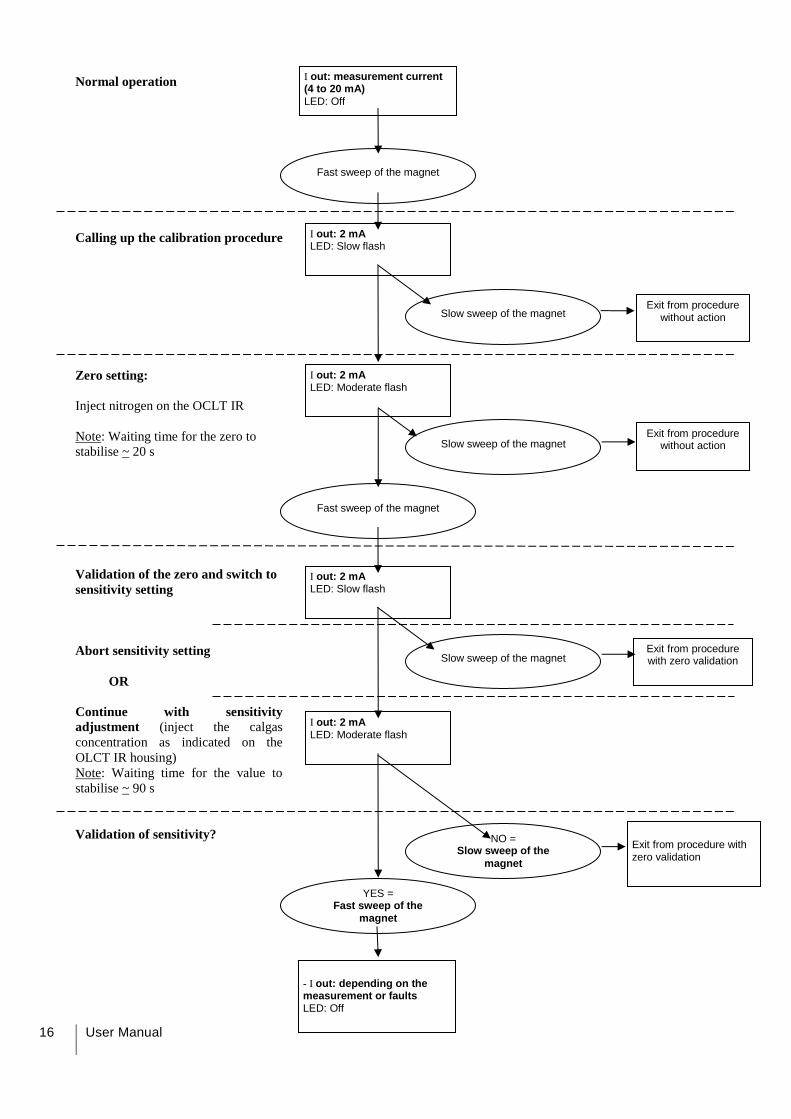
16 User Manual
Normal operation
Calling up the calibration procedure
Zero setting:
Inject nitrogen on the OCLT IR
Note: Waiting time for the zero to
stabilise ~ 20 s
Validation of the zero and switch to
sensitivity setting
Abort sensitivity setting
OR
Continue with sensitivity
adjustment (inject the calgas
concentration as indicated on the
OLCT IR housing)
Note: Waiting time for the value to
stabilise ~ 90 s
Validation of sensitivity?
I out: measurement current (4 to 20 mA)
LED: Off
Fast sweep of the magnet
I out: 2 mA LED: Slow flash
Exit from procedure without action
Slow sweep of the magnet
I out: 2 mA LED: Moderate flash
Slow sweep of the magnet Exit from procedure
without action
Fast sweep of the magnet
I out: 2 mA LED: Slow flash
Slow sweep of the magnet Exit from procedure with zero validation
I out: 2 mA LED: Moderate flash
NO = Slow sweep of the
magnet
Exit from procedure with zero validation
YES = Fast sweep of the
magnet
- I out: depending on the measurement or faults LED: Off
5 – Maintenance 17
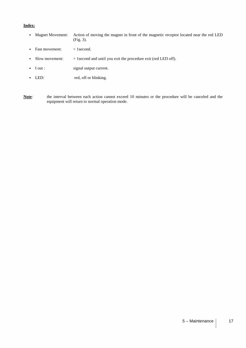
Index:
Magnet Movement: Action of moving the magnet in front of the magnetic receptor located near the red LED
(Fig. 3).
Fast movement: < 1second.
Slow movement: > 1second and until you exit the procedure exit (red LED off).
I out : signal output current.
LED: red, off or blinking.
Note: the interval between each action cannot exceed 10 minutes or the procedure will be canceled and the
equipment will return to normal operation mode.
18 User Manual
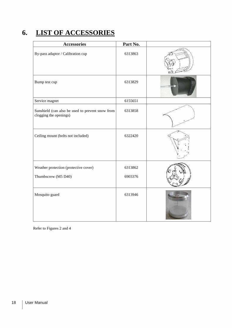
6. LIST OF ACCESSORIES
Accessories Part No.
By-pass adaptor / Calibration cup
6313863
Bump test cup
6313829
Service magnet 6155651
Sunshield (can also be used to prevent snow from
clogging the openings)
6313858
Ceiling mount (bolts not included)
6322420
Weather protection (protective cover)
Thumbscrew (M5 D40)
6313862
6903376
Mosquito guard
6313946
Refer to Figures 2 and 4

7 – Special instructions for use in
ATEX explosive atmospheres 19
20 User Manual
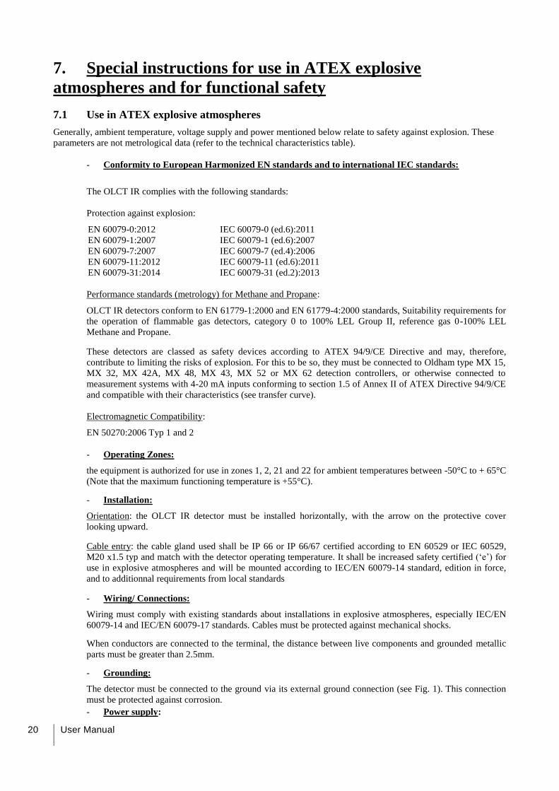
7. Special instructions for use in ATEX explosive
atmospheres and for functional safety
7.1 Use in ATEX explosive atmospheres
Generally, ambient temperature, voltage supply and power mentioned below relate to safety against explosion. These
parameters are not metrological data (refer to the technical characteristics table).
- Conformity to European Harmonized EN standards and to international IEC standards:
The OLCT IR complies with the following standards:
Protection against explosion:
EN 60079-0:2012 IEC 60079-0 (ed.6):2011
EN 60079-1:2007 IEC 60079-1 (ed.6):2007
EN 60079-7:2007 IEC 60079-7 (ed.4):2006
EN 60079-11:2012 IEC 60079-11 (ed.6):2011
EN 60079-31:2014 IEC 60079-31 (ed.2):2013
Performance standards (metrology) for Methane and Propane:
OLCT IR detectors conform to EN 61779-1:2000 and EN 61779-4:2000 standards, Suitability requirements for
the operation of flammable gas detectors, category 0 to 100% LEL Group II, reference gas 0-100% LEL
Methane and Propane.
These detectors are classed as safety devices according to ATEX 94/9/CE Directive and may, therefore,
contribute to limiting the risks of explosion. For this to be so, they must be connected to Oldham type MX 15,
MX 32, MX 42A, MX 48, MX 43, MX 52 or MX 62 detection controllers, or otherwise connected to
measurement systems with 4-20 mA inputs conforming to section 1.5 of Annex II of ATEX Directive 94/9/CE
and compatible with their characteristics (see transfer curve).
Electromagnetic Compatibility:
EN 50270:2006 Typ 1 and 2
- Operating Zones:
the equipment is authorized for use in zones 1, 2, 21 and 22 for ambient temperatures between -50°C to + 65°C
(Note that the maximum functioning temperature is +55°C).
- Installation:
Orientation: the OLCT IR detector must be installed horizontally, with the arrow on the protective cover
looking upward.
Cable entry: the cable gland used shall be IP 66 or IP 66/67 certified according to EN 60529 or IEC 60529,
M20 x1.5 typ and match with the detector operating temperature. It shall be increased safety certified (‘e’) for
use in explosive atmospheres and will be mounted according to IEC/EN 60079-14 standard, edition in force,
and to additionnal requirements from local standards
- Wiring/ Connections:
Wiring must comply with existing standards about installations in explosive atmospheres, especially IEC/EN
60079-14 and IEC/EN 60079-17 standards. Cables must be protected against mechanical shocks.
When conductors are connected to the terminal, the distance between live components and grounded metallic
parts must be greater than 2.5mm.
- Grounding:
The detector must be connected to the ground via its external ground connection (see Fig. 1). This connection
must be protected against corrosion.
- Power supply:
7 – Special instructions for use in
ATEX explosive atmospheres 21
Voltage at detector terminals = 30 VDC max, 16 VDC min.
Max power = 5.8 Watts
- Replacing screws:
If you need to replace a screw from the “Ex d” flameproof housing, use an A4.70 or a screw of higher quality.
- Dusty atmospheres:
When using the equipment in dust explosive atmospheres, the equipment should be thoroughly cleaned on a
regular basis to prevent dust buildup. The dust layer shall be less than 5 mm thick. The joints between the
housing and the sensor part or between the housing and the terminal block cover will be coated with paraffinic
grease.
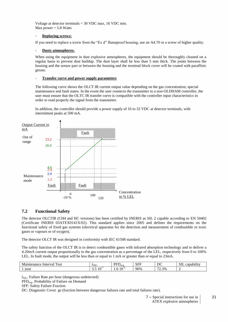
- Transfer curve and power supply parameters
The following curve shows the OLCT IR current output value depending on the gas concentration, special
maintenance and fault states. In the event the user connects the transmitter to a non-OLDHAM controller, the
user must ensure that the OLTC IR transfer curve is compatible with the controller input characteristics in
order to read properly the signal from the transmitter.
In addition, the controller should provide a power supply of 16 to 32 VDC at detector terminals, with
intermittent peaks at 500 mA.
7.2 Functional Safety
The detector OLCTIR (CH4 and HC versions) has been certified by INERIS as SIL 2 capable according to EN 50402
(Certificate INERIS 03ATEX0141X/02). This standard applies since 2005 and defines the requirements on the
functional safety of fixed gas systems (electrical apparatus for the detection and measurement of combustible or toxic
gases or vapours or of oxygen).
The detector OLCT IR was designed in conformity with IEC 61508 standard.
The safety function of the OLCT IR is to detect combustible gases with infrared absorption technology and to deliver a
4-20mA current output proportionally to the gas concentration as a percentage of the LEL, respectively from 0 to 100%
LEL. In fault mode, the output will be less than or equal to 1 mA or greater than or equal to 23mA.
Maintenance Interval Test λDU PFDavg SFF DC SIL capability
1 year 3.5 10-7
1.6 10-3
90% 72.3% 2
λDU : Failure Rate per hour (dangerous undetected)
PFDavg : Probability of Failure on Demand
SFF: Safety Failure Fraction
DC: Diagnostic Coverage (fraction between dangerous failures rate and total failures rate).
0
% 100
%
20,0
mA
4,0
mA 2.4
mA
Concentration
En % LIE
Sortie Courant en mA
Défaut
23,2
mA
Défaut
1.2
mA
Mode
Maintenance
120
%
-10 %
Hors
gamme
Défaut
2.0
mA
Concentration
in % LEL
Output Current in
mA
Fault
Fault
Fault
Out of
range
Maintenance
mode
22 User Manual
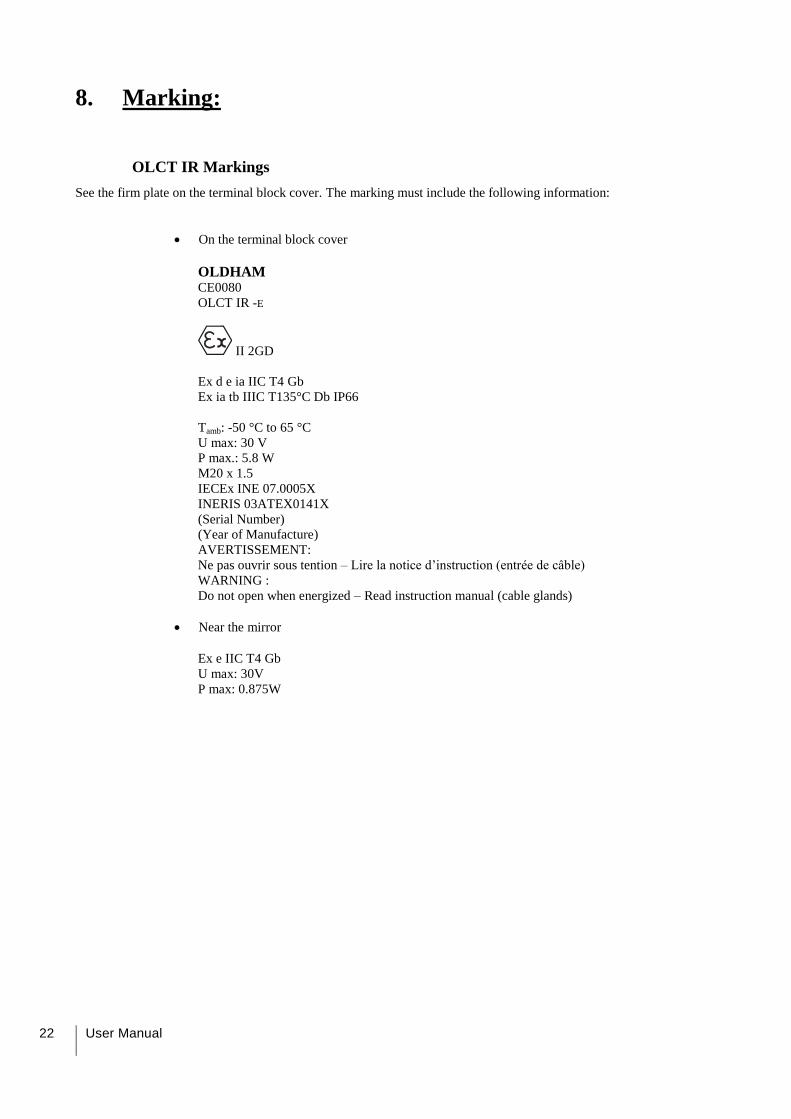
8. Marking:
OLCT IR Markings
See the firm plate on the terminal block cover. The marking must include the following information:
On the terminal block cover
OLDHAM
CE0080
OLCT IR -E
II 2GD
Ex d e ia IIC T4 Gb
Ex ia tb IIIC T135°C Db IP66
Tamb: -50 °C to 65 °C
U max: 30 V
P max.: 5.8 W
M20 x 1.5
IECEx INE 07.0005X
INERIS 03ATEX0141X
(Serial Number)
(Year of Manufacture)
AVERTISSEMENT:
Ne pas ouvrir sous tention – Lire la notice d’instruction (entrée de câble)
WARNING :
Do not open when energized – Read instruction manual (cable glands)
Near the mirror
Ex e IIC T4 Gb
U max: 30V P max: 0.875W

8 – Marking 23

24 User Manual
9. Manufacturer’s Declaration of Conformity

9 – Declaration of conformity 25

26 User Manual

27

The Fixed Gas Detection Experts
EUROPEAN PLANT AND OFFICES
Z.I.Est – rue Orfila CS 20417 – 62027 Arras Cedex FRANCE Tél: +33 (0)3 21 60 80 80 – Fax: +33 (0)3 21 60 80 00
Website: http://www.oldhamgas.com
AMERICAS Tel: +1 713-559-9280 Fax: +1 281-292-2860
ASIA PACIFIC Tel: +86-21-3127-6373 Fax: +86-21-3127-6365 [email protected]
EUROPE Tel: +33-321-608-080 Fax: +33-321-608-000 [email protected]