new eagle data logger · new eagle data logger – sd side new eagle data logger ... turn the key...
TRANSCRIPT

Page | 1
New Eagle Data Logger
User Guide V7.0
New Eagle
10/2/2012

Page | 2
Table of Contents Overview ....................................................................................................................................................... 4
Kit Contents ............................................................................................................................................... 5
Quick Start ................................................................................................................................................. 6
Setup ............................................................................................................................................................. 6
Connector Pins .......................................................................................................................................... 6
Harness ..................................................................................................................................................... 7
Logger Switches, LED’s and More…. ............................................................................................................. 7
LED’s .......................................................................................................................................................... 7
Reset Button ............................................................................................................................................. 8
This is for use only as directed by a MoibilEyze support engineer. If inadvertently pressed, the unit
can be reset by removing all power for 20 seconds. ................................................................................ 8
Real-Time Clock ......................................................................................................................................... 8
User Action Button .................................................................................................................................... 8
SD Card Slot ............................................................................................................................................... 8
Serial Port .................................................................................................................................................. 8
Data Logging.................................................................................................................................................. 9
Closing a log session .................................................................................................................................. 9
Log Files ..................................................................................................................................................... 9
Standard ................................................................................................................................................ 9
Circular .................................................................................................................................................. 9
File Layout ............................................................................................................................................... 10
Configuration File ........................................................................................................................................ 12
File Name ................................................................................................................................................ 12
Parameters .............................................................................................................................................. 12
Configuration File Format ....................................................................................................................... 13
Updating the Date and Time ....................................................................................................................... 13
Date Time CAN Message ......................................................................................................................... 13
Preparing the module for the Date Time CAN Message ......................................................................... 14
Upgrading Firmware ................................................................................................................................... 14
(Page reserved for Table of Contents expansion)
Page | 3
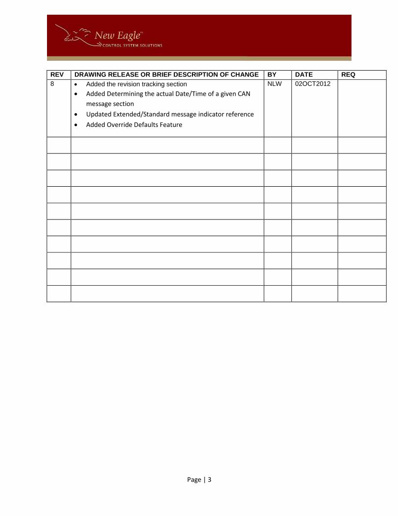
REV DRAWING RELEASE OR BRIEF DESCRIPTION OF CHANGE BY DATE REQ
8 Added the revision tracking section
Added Determining the actual Date/Time of a given CAN
message section
Updated Extended/Standard message indicator reference
Added Override Defaults Feature
NLW 02OCT2012

Page | 4
Overview Congratulations on your purchase of the New Eagle Data Logger. The logger was designed to be the
most capable and lowest cost CAN data logger solution available. The logger is capable of logging at
rates as low as 1ms, supports both 11bit and 29bit messages, and can be configured to meet the needs
of your environment. Continue reading to learn about all of its capabilities. We understand that many
of you will just want to start logging and learn later so we created a Quick Start section just for you!
New Eagle Data Logger – SD Side New Eagle Data Logger – Connector Side
New Eagle Data Logger – SD Side

Page | 5
Kit Contents The kit includes:
1. The New Eagle Data Logger
New Eagle Data Logger – SD Side New Eagle Data Logger – Connector Side
2. The New Eagle Data Logger harness (Sold separately)
New Eagle Data Logger – SD Side

Page | 6
Quick Start
To… See…
Connect the device to the CAN bus Setup
Read about the operational statuses and board components
LED’s Or Board Components and Cables
Read about the data logging details Data Logging
Read about the configuration file Configuration File
Setup The logger is ready to use out of the box and is configured for a bus baud rate of 250K. To start logging
follow these simple steps:
1. Connect the logger with the harness (sold separately).
2. Connect the Delphi 10 pin connector to an open port on compatible J-Box.
3. Apply power to the CAN bus along with a key switch through the same J-Box.
4. Turn the key switch on and the logger will power on and begin logging all CAN data.
Connector Pins
Pin Purpose
1 Key switch * The logger utilizes the presence of a key switch to determine when it can close a log session and power itself off. The default behavior can be overridden by wiring a power source to this pin. NOTE: Overriding the key switch prevents the unit from detecting when to close a log session and some data could be lost as a result.
2 VBatt * The expects power on this pin unless it is alternatively supplied on Pin 1.
3 Ground Must be wired to the appropriate system ground.
4 Not Used
5 Not Used
6 Digital Input Can be used as a User Action button
7 CAN H CAN high
8 CAN L CAN low
9 RS232 Rx Serial receive – Note that the system ground should also be used when wiring a serial connector to the logger
10 RS232 Tx Serial transmit
*The logger is configured to utilize the combination of a key switch and VBatt to properly detect when it
is safe to close a log session. Though this is the recommended configuration the logger can function
without the use of a key switch. To eliminate the key switch remove power from pin 2 and place it on
pin 1. BE AWARE THAT THE LOGGER CAN NO LONGER ENSURE PROPER FILE CLOSURES AND SOME DATA
LOSS MAY OCCUR.

Page | 7
Harness A harness is available is designed to mate the logger with a CAN bus environment that utilizes a Smartcraft connector on the CAN hub side.
Pin Wire Color Purpose
1 Violet Key switch
2 Red VBatt
3 Black Ground
7 White CAN H
8 Blue CAN L
Logger Switches, LED’s and More…. The logger is equipped with Switches and more. There are two sides to the logger. One side contains the connector for the harness, the reset button, and the state-of-health LED. The other side contains the slot for the SD card, the User-Action button, and two more LEDS that provide indications for logging and CAN bus activity.
LED’s
State-of-Health LED File System and CAN Status LED’s
There are three LED’s, two on the SD Card slot side and one on the connecter side.
LED Location Reference Description
1 Connector Side State-of-health Blinking Green = Normal operation Red = Error, unit must be reset Blinking Orange = Shutting down
2 SD Side – closest to SD
File System Blinking Orange = Waiting for SD Card Orange = SD Card detected Green = System is ready to log Blinking Green = data is being logged Blinking Red = SD Card is write protected Red = File System Error – SD card may be full or
needs to be replaced.
3 SD Side – closest to User Action Switch
CAN Status Green = Ready Blinking Green = CAN Data present Blinking Orange = Waiting for data Blinking Red = CAN bus is in error passive state Red = Error, unit must be reset

Page | 8
Reset Button
This is for use only as directed by a MoibilEyze support engineer. If inadvertently pressed, the unit can
be reset by removing all power for 20 seconds.
Real-Time Clock The logger is equipped with a real-time clock that is set at the factory prior to shipping and is maintained
using an internal battery. The battery has an expected life of 10 years but may need to be replaced
sooner. It is safe to open the unit (with the harness removed) to replace the battery. The logger
requires a CR2032 battery.
User Action Button The user action button is located on the SD side and can be used to insert a [User Action] stamp into the
log file whenever the user desires.
The User Action button can also be utilized to close an active logging session, eliminating the need to
key the system off to close the session. Press and hold the User Action button until the File System LED
turns off. It is safe to remove the SD card when the light goes off. To put the logger back into logging
mode hold the User Action button again until the LED turns or blinks green.
SD Card Slot The SD Card slot accepts standard SD cards. The system is compatible with most SD Cards with a
maximum capacity of 8GB. The LED’s can be consulted to indicate if the inserted card is supported.
An SD card has been provided and contains security information required for the proof-of-concept to
function. The SD card must be returned with the unit when the evaluation period is complete.
Serial Port The logger has a serial port that can be used to view detailed trace information from the software. The
information can be useful in troubleshooting problems.
The serial port configuration values are:
Parameter Value
Baud Rate 115200
Data 8 bit
Parity None
Stop Bit 1
Flow Control None
See the Connector Pins section of this guide for details about the pins needed to utilize the serial output.

Page | 9
Data Logging The logger utilizes a standard SD card up to 16GB. The logger looks for the presence of an SD Card at
start up. If one isn’t present the File System LED will blink orange to indicate that it’s waiting for an SD
card. An SD card can be inserted at any time and the File System LED will change to reflect the new
status.
By default the logger is configured to log all data using a baud rate of 250K. A configuration file can be
used to change the baud rate or filter the CAN data. See the Configuration File section for more details.
Closing a log session The logger utilizes the keyswitch pin to determine when to start and stop. The key switch indicates to
the logger that it is safe to close the session file. The logger keeps itself powered while it closes the
session and then allows itself to shut down.
The User Action button can also be used to close a session and initiate a new session. Simply hold the
User Action button until the File System LED turns off. Then hold it again until the LED turns or blinks
green to initiate a new session.
Log Files The logger has two type of logging mechanisms which are described below.
Standard
The system creates log files using utilizes the loggers date and time. The date serves as the main folder
and the time serves as the file name within the folder. The logger will continue to run until there isn’t
any space available for creating new files. The result is that all data is maintained until removed from
the SD card. This is an ideal mechanism for an engineering environment.
Circular
This mode utilizes a total of five files named LOG_001.MEL through LOG_005.MEL. At startup the logger
will rename LOG_004.MEL to LOG_005.MEL, LOG_003.MEL to LOG_004.MEL, LOG_002.MEL to
LOG_003.MEL, and finally, LOG_001.MEL to LOG_002.MEL. It will then utilize LOG_001.MEL for the
active session. The result is a circular mechanism and is ideal for production environments.

Page | 10
File Layout All lines are terminated with the standard \r\n (0x0D, 0x0A) characters.
Reference Description
[Header] Indicates the start and end of the header data.
Header Contains revision information and the configuration details used for the log file:
MobilEyzeLogger=Vx.x BusSpeed=250K Baud Filter=0x170,0x170,F (there can be up to 10 filters)
Data Data lines formatted with the following format string: %08x,%01d,%01d,%02x,%02x,%02x,%02x,%02x,%02x,%02x,%02x, %d,%d\r\n Represented with id’s it looks like: MsgId, Extended, Size, Byte[0], Byte[1], Byte[2], Byte[3], Byte[4], Byte[5], Byte[6], Byte[7], Time,Delta\r\n Where: MsgId : The message id Extended : T if it’s an extended message, F otherwise Size: The number of bytes of data received in the message Byte[0..7]: The data received in the message Time Stamp: The # of seconds since the CPU started, in the format of #.000000. Delta: The microsecond delta from the time of the last message.
[End] Indicates the end of the data for that session.
Determining the actual Date/Time of a given CAN message Users have expressed a desire to know how to determine the actual date/time of a given CAN message.
Following is a sample file that we’ll use for the discussion.
---- START OF FILE -----
[Header, Start Time=Mon Sep 24 17:02:09 2012, TimeStamp=2.069340]
MobilEyzeLogger=V01.999.dirty
BusSpeed=250K Baud
Filter=0x0,0x7ff,F
Filter=0x0,0x1fffffff,T
Using Standard Logging
[Header - End]
0x00000000,1,8,0x00,0x00,0x00,0x00,0x00,0x00,0x00,0x00,9726.191841,0.000000
0x00000001,1,8,0x01,0x00,0x00,0x00,0x00,0x00,0x00,0x00,9727.191712,0.999871

Page | 11
0x00000002,1,8,0x02,0x00,0x00,0x00,0x00,0x00,0x00,0x00,9728.191804,1.000092
0x00000003,1,8,0x03,0x00,0x00,0x00,0x00,0x00,0x00,0x00,9729.191807,1.000003
0x00000004,1,8,0x04,0x00,0x00,0x00,0x00,0x00,0x00,0x00,9730.191858,1.000051
0x00000005,1,8,0x05,0x00,0x00,0x00,0x00,0x00,0x00,0x00,9731.191809,0.999951
[End of Log, End Time=Mon Sep 24 19:44:23 2012, TimeStamp=9735.151937]
---- End of File -------
Header
Example: [Header, Start Time=Mon Sep 24 17:02:09 2012, TimeStamp=2.069340]
The TimeStamp=2.069340 value represents the number of seconds that elapsed since the CPU started,
further referenced as Header Time Stamp. In this case it indicates that 2.069340 seconds elapsed before
the header was written to the file. All date references should then be calculated using the Header Time
Stamp value.
Line Item Tick Count
The line item tick count can be found in the 12th value of the CAN message (See File Layout for more
details):
Example: 0x00000000,1,8,0x00,0x00,0x00,0x00,0x00,0x00,0x00,0x00,9726.191841,0.000000
The Time Stamp is 9726.191841.
Note: It is possible to have CAN messages with a Time Stamp that is prior to that found in the header.
This is because the RTOS caches CAN messages and then dispatches them to the application once it’s
ready to receive.
Calculation
The actual time of a given line item can be calculated by subtracting the Time Stamp in the CAN message
from the Time Stamp in the Header. The resulting value indicates the number of seconds that have
elapsed since the header was written. The resulting value should added to the date/time value found in
the header. Note that the resulting value can be negative and indicates that the CAN message was
received before the header was written.

Page | 12
Configuration File The application can be configured using a simple text file that can be created manually (see the
Configuration File Format section below for details).
File Name The configuration file must be named LOGGER.MEC.
Parameters The following table describes the parameters for the configuration file.
Parameter Format Default Comment
BusSpeed See comment
250K Must be one of the following: 100K | 125K | 250K | 500K | 1M
Filter SMSGID,EMSGID,EXT
0x0,0x7FF,S 0x0,0x1FFFFFFFF,E
All standard messages All extended messages Where: SMSGID = start id EMSGID = end id EXT = E for extended S for standard
OutputDebugToCAN T/F F Trace messages will be echoed to the CAN bus. CANId is required for this feature.
UseErrorPassiveDetection T/F F When set to ‘T’rue the logger will look for error passive conditions. It must periodically broadcast a message to determine the state. CANId is required for this feature. The broadcast message consists of a single byte message with the value of 0x55.
CANId 0x## 0xFE The id to use when talking on the bus. The user should take care to choose an ID that is safe to transmit on the CAN bus. Error Passive Detection is disabled if this value isn’t supplied.
LogType C/S S C=Circular S = Standard
AutoFlush T/F F Protects logged data from power loss. When set to ‘T’ the logger issues a flush command with each write. NOTE: This can impact performance for some SD cards. See our website for a list of the best performing SD cards.
OverrideDefaults T/F F Override the application defaults. When set to true the values in the configuration file will become the new defaults.

Page | 13
Configuration File Format The configuration file is a standard text file containing parameters that are used to configure the application. Each parameter must be entered on a separate line followed by an = sign, followed by the value, terminated by Carriage Return (0x0A) and Line Feed(0x0D) characters . The following represents the content of a configuration file containing the default values:
BusSpeed=250K Filter=0x0,0x1ef,S Filter=0x0,0x1fbfffff,E OutputDebugToCAN=T UseErrorPassiveDetection=F CANId=0xfe
Updating the Date and Time The unit ships from the factory with its date and time set from the factory using GMT time. The default
date and time settings can be overridden. This section describes the necessary procedure for changing
the date and time settings.
Date Time CAN Message The date and time can be set by sending the logger a CAN message that contains the date/time in a 4
byte unix epoch format (See http://www.epochconverter.com/). Following are the details for the CAN
Message:
Message Id = 0x101 (11-Bit Message)
Message Length = 4
Data Description
0 Epoch date time (LSB)
1 Epoch date time

Page | 14
2 Epoch date time
3 Epoch date time (MSB)
Preparing the module for the Date Time CAN Message The module must be put in “Test Mode” in order for it to process the Date Time CAN Message using the
following steps:
1. Power the unit off.
2. Hold the User Action button and power the unit on.
3. Hold the User Action button for at least three seconds. The module indicates that it’s in test
mode when all the lights are orange. The lights will remain orange for three seconds.
4. The module is ready for the Date Time CAN message when the lights begin alternating colors.
5. Send the Date Time CAN Message. The unit will respond with a 0x201 and the data reflects the
modules date and time.
6. Power the unit off.
7. The date and time have been set.
Upgrading Firmware The unit’s firmware can be updated using an SD Card. Follow these easy steps:
1. Obtain the latest firmware from our website or the Reseller Package (currently
DataLogger_Version_1.020.zip).
2. Unzip the contents to a folder of your choice.
3. Copy the file with that contains B4.1 (currently DataLogger_DataLoggerRevB4.1.bin) to an SD
card.
4. Rename the file on the SD card to Firmware.bin
5. Make sure the logger is powered off and insert the SD card into the logger.
6. Turn power on – you will see the State-of-Health pin turn solid green for a short moment. It will
then change to blinking green when the new application is loaded.
7. Test by logging data and observing the version number in the log file.