new directions for electrokinetic remediation research - uma · krishna r. reddy, claudio cameselle...
TRANSCRIPT

New Directions for Electrokinetic Remediation Research
Krishna R. Reddy, PhD, PE, DGE, FASCEProfessor of Civil & Environmental Engineering
Director, Geotechnical & Geoenvironmental LaboratoryUniversity of Illinois, Chicago, USA
13th Symposium on Electrokinetic Remediation (EREM2014)Malaga, Spain, September 8, 2014

Presentation Outline
1. Status on Electrokinetic Remediation
2. Current Research Trends
3. Practical Issues/Considerations
4. Final Remarks

The Problem
Estimated Number of Contaminated Sites in the U.S. (Cleanup horizon: 2004 – 2033)
Just started to realize the problem in developing countries such as India, China,...

Remediation Technologies
Soil Remediation•Soil Vapor Extraction
•Soil Washing/Flushing
•Chemical Oxidation/Reduction
•Stabilization/Solidification
•Electrokinetic Remediation
•Thermal Desorption
•Vitrification
•Bioremediation
•Phytoremediation
Groundwater Remediation•Pump and Treat
•In-Situ Flushing
•Permeable Reactive Barriers
•Air Sparging
•Monitored Natural Attenuation
•Bioremediation
Still striving to develop efficient, rapid and cost-effective in-situ technologies?

Electrokinetic Remediation (EKR)
Fundamentals:
•Electrolysis•Electromigration•Electroosmosis•Electrophoresis•Geochemical Reactions
•Adsorption/Desorption•Precipitation/Dissolution•Oxidation/Reduction•Complexation Rxns•…
Dynamic geochemistry Spatial and temporal changes in solution chemistry and solid surface properties

Unique Advantages
� Applicable to Different Soil Conditions� Low Permeability/Heterogeneous Soils
� Unsaturated and Saturated Soils
� Applicable to Variety of Contaminants� Metals, Radionuclides, or Organic Compounds
� Mixed Contaminants
� Easy to integrate with other remediation technologies

Electrokinetic Remediation: Overview
Krishna R. Reddy, Claudio Cameselle(Editors)
ISBN: 978-0-470-38343-8Hardcover. 760 pages. September 2009.
www.wiley.com
Electrochemical Remediation Technologies for Polluted Soils, Sediments and Groundwater
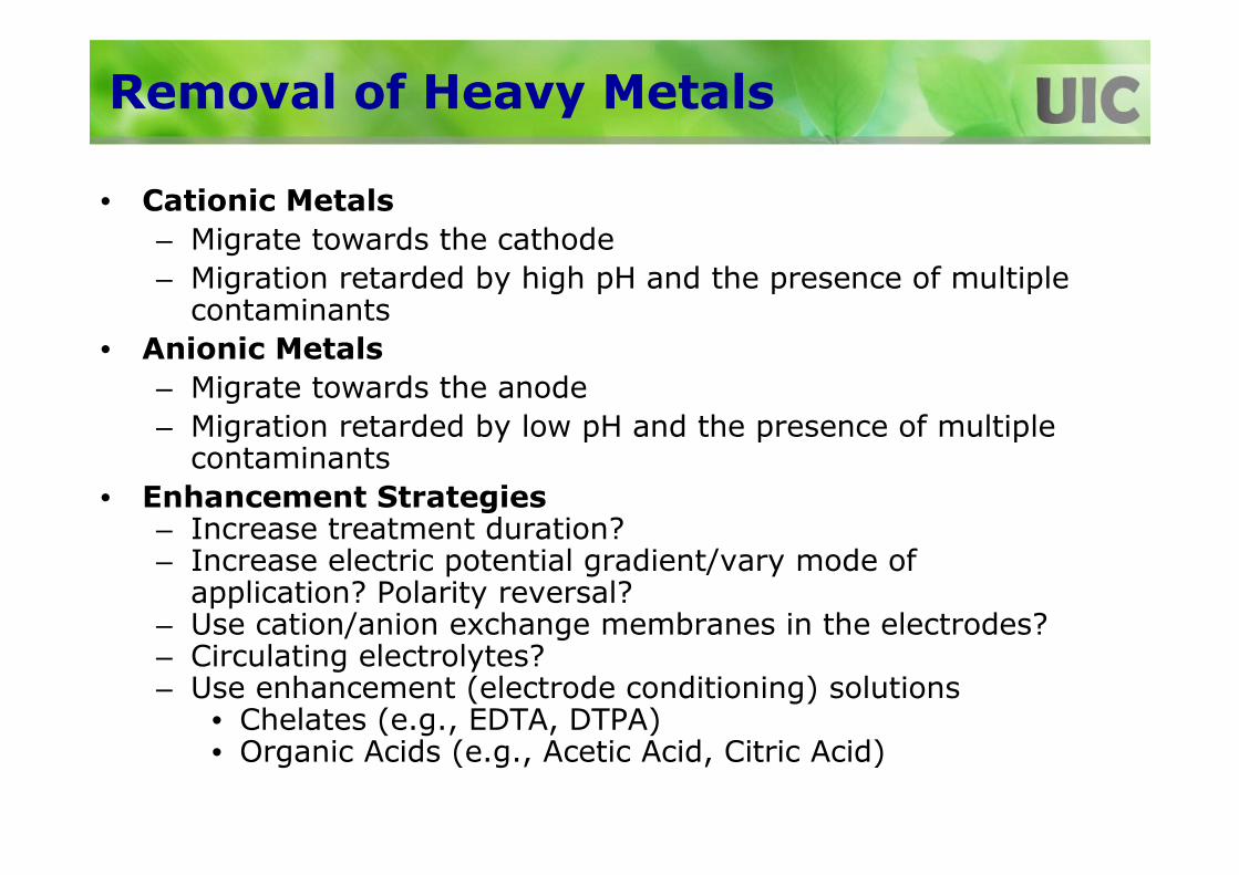
Removal of Heavy Metals
• Cationic Metals
– Migrate towards the cathode
– Migration retarded by high pH and the presence of multiple contaminants
• Anionic Metals
– Migrate towards the anode
– Migration retarded by low pH and the presence of multiple contaminants
• Enhancement Strategies– Increase treatment duration?– Increase electric potential gradient/vary mode of
application? Polarity reversal?– Use cation/anion exchange membranes in the electrodes?– Circulating electrolytes?– Use enhancement (electrode conditioning) solutions
• Chelates (e.g., EDTA, DTPA)• Organic Acids (e.g., Acetic Acid, Citric Acid)

Removal of Organic Contaminants
Hydrophobic organic contaminants must be desorbed/solubilized using:•Surfactants•Cosolvents•Cyclodextrins
Removal depends upon electroosmosis (EO), but EO decreases due to: reduced electrical conductivity, reduced soil pH (<PZC), and the type of flushing solution used
Sustain/increase EO by:•pH control (>PZC throughout the soil)•Magnitude/Mode of electric potential application (e.g., pulsed- on/off cycles)

Integrated/Coupled Technologies
• Integrated (or Coupled) Technologies such as– Electrokinetic Chemical Oxidation/Reduction– Electrokinetic Bioremediation– Electrokinetic Phytoremediation– Electrokinetic Permeable Reactive Barriers– Electrokinetic Stabilization– …
• Advantages– Overcome the deficiencies of common technologies– Detoxify organics within the soil/groundwater (no effluent to
treat)– Remove/recover heavy metals (no long-term issues/value)– Achieve both of the above (ideal for mixed contaminants)– Practical?– Cost-effective?

EKR Current Status
� Electrokinetic remdiation by itself or with enhancements may be costly and impractical.
� Integrated electrokinetic remediation technologies have great potential to be effective and practical.
� Ideally suited for:� Remediation of low permeability/heterogeneous subsurface� Source zone remediation� Difficult contaminants� Mixed contaminants
� Provides greater flexibility to adapt at any time during the remediation process to changing or different contaminant conditions, without the need for major changes in the field setup
Topic=(electrokinetic remediation)
Results: 885
Source: Web of Science
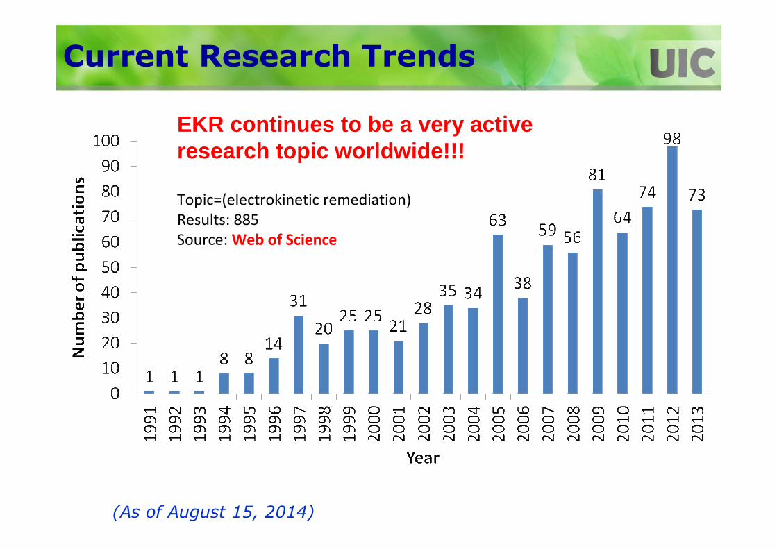
Current Research Trends
(As of August 15, 2014)
EKR continues to be a very active research topic worldwide!!!

Topic=(electrokinetic remediation)
Results: 885
Source: Web of Science
(As of August 15, 2014)
EKR Publications

Topic=(electrokinetic remediation)
Results: 2957
Source: Google Scholar
(As of August 15, 2014)
EKR Publications

Topic=(electrokinetic remediation)
Results: 2957
Source: Google Scholar
(As of August 15, 2014)
EKR Publications
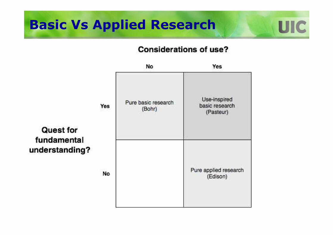
Basic Vs Applied Research

Practical Issues/Considerations
1. Reliability of the technology
2. Costs of application
3. Practicality of implementation
4. Application of and ability to meet risk-based remediation goals
5. Anticipated remediation time
6. Acceptability to project stakeholders
7. Necessity of special permits
8. Implications on end-use of the site
9. Sustainability considerations, including triple bottom line parameters
10.Remediation versus management paradigm for complex sites
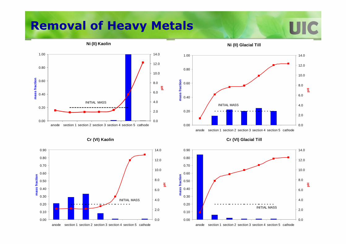
Removal of Heavy Metals
0.0
2.0
4.0
6.0
8.0
10.0
12.0
14.0
0.00
0.20
0.40
0.60
0.80
1.00
anode section 1 section 2 section 3 section 4 section 5 cathode
pH
mas
s fr
actio
n
Ni (II) Kaolin
INITIAL MASS
Cr (VI) Glacial Till
0.00
0.10
0.20
0.30
0.40
0.50
0.60
0.70
0.80
0.90
anode section 1 section 2 section 3 section 4 section 5 cathode
mas
s fr
actio
n
0.0
2.0
4.0
6.0
8.0
10.0
12.0
14.0
pH
INITIAL MASS
Ni (II) Glacial Till
0.00
0.20
0.40
0.60
0.80
1.00
anode section 1 section 2 section 3 section 4 section 5 cathode
mas
s fr
actio
n
0.0
2.0
4.0
6.0
8.0
10.0
12.0
14.0
pH
INITIAL MASS
Cr (VI) Kaolin
0.00
0.10
0.20
0.30
0.40
0.50
0.60
0.70
0.80
0.90
anode section 1 section 2 section 3 section 4 section 5 cathode
mas
s fr
actio
n
0.0
2.0
4.0
6.0
8.0
10.0
12.0
14.0
pH
INITIAL MASS

Enhanced Heavy Metal Removal
12
0
7
83
10
2320 19
12
6871
94
0
10
20
30
40
50
60
70
80
90
100
Chromium Nickel Cadmium
% R
emo
val
Overall Removal EfficiencyKaolin
WaterEDTAAcetic AcidSQEEK

Enhanced Heavy Metal Removal
Overall Removal EfficiencyGlacial Till
17
10
0
46
0 0
79
1410
82
1416
73
0 0
58
49
26
0
10
20
30
40
50
60
70
80
90
Chromium Nickel Cadmium
% R
emo
val
Water
EDTA
Acetic Acid
Citric Acid
Sulfuric Acid
SQEEK

Removal of Organic Contaminants
0
500
1000
1500
2000
2500
0 50 100 150 200 250 300Elapsed Time (days)
Cu
mu
lati
ve F
low
Vo
lum
e (m
L)
PeriodicContinuous
Kaolin; Phenanthrene=500 mg/kgAnode: 0.01M NaOH/Surfactant; VG=2 VDC/cm
0
0.25
0.5
0.75
1
1.25
1.5
1.75
2
0 0.2 0.4 0.6 0.8 1
No
rmal
ized
Co
nce
ntra
tion
C/C
o
Normalized Distance from Anode
PeriodicContinuous

Removal of Mixed Contaminants
EK-NP-1: 5% Igepal
012345678
0 0.2 0.4 0.6 0.8 1Normalized distance from Anode
Con
cent
ratio
n (C
/Co
) Nickel
Phenanthrene
(Conc. 500 mg/kg each; 2 VDC/cm-periodic)

H2O2 Conc.
0
100
200
300
400
500
600
0 0.2 0.4 0.6 0.8 1
Normalized Distance from Anode
Ph
enan
thre
ne
Co
nce
ntr
atio
n
(mg
/Kg
)
Initial0%5%10%20%30%
Integrated EK-Fenton
Kaolin Soil with Phenanthrene and Nickel (each at 500 mg/kg); VG=1 VDC/cm

H2O2 Conc.
0
500
1000
1500
2000
2500
3000
0 0.2 0.4 0.6 0.8 1
Normalized Distance from Anode
Nic
kel C
on
cen
trat
ion
(m
g/K
g)
Initial0%5%10%20%30%
Co-Existing Ni Removal
Kaolin Soil with Phen and Nickel (each at 500 mg/kg)

Field Contaminated Soils
PROPERTY Field A* Soil B** Soil D* Soil E*% gravel = 0 % gravel = 0 % gravel = 1.8 - 15.4 % gravel = 0.1
Grain size distribution % sand = 84.0 % sand = 5.2 % sand = 50.1- 65.6 % sand = 8.4% fines = 16.0 % fines = 94.8 % fines = 32.6 - 34.5 % fines = 91.5
LL = 50.0 LL = 45.0Atterberg limits Non-Plastic PL = 24.0 Non-Plastic PL = 31.7
PI = 26.0 PI = 13.7USCS classification SP-SM CH - fat clay SM CL
Water content N/A 6.36% 7.55% 78.60%Organic content 11.10% 2.63% 2.69% - 3.75% 19.20%Specific gravity 2.68 2.52 2.54 1.25Max. dry density N/A N/A 2.03 g/cm3 1.35 g/cm3
Optimum moisture content N/A N/A 10.40% 24.00%pH 7 7.56 6.9 7
Redox porential -0.05 mV -58.1 mV 186.4 mV 184.3 mVElectrical conductivity 2.68 m-s/cm 11.58 m-s/cm 1435 m-s/cm 0.37 m-s/cm
All the soil properties were determined by ASTM standards*Contaminated with both heavy metals and PAHs** Contaminated with heavy metals only

Testing Program
9 EK-B-1 2 0.2M EDTA 1.910 EK-B-2 2 0.2M KI 0.2811 EK-B-3 2 0.2M DTPA 1.512 EK-B-4 2 10% HP-β - CD 0.813 EK-B-5 2 0.2M KI -14 EK-B-6 2 0.2M EDTA -15 EK-B-7 1 0.2M KI -16 EK-B-8 1 0.2M EDTA -17 EK-D-1 2 5% Igepal CA-720 7.218 EK-D-2 2 10% HP-β - CD 7.519 EK-D-3 2 20% n-Butylamine 10.720 EK-D-4 2 3% Tween 80 2.121 EK-E-1 2 5% Igepal CA-720 1122 EK-E-2 2 10% HP-β - CD 5.323 EK-E-3 2 20% n-Butylamine 14.724 EK-E-4 2 3% Tween 80 15.9
Test Testing Voltage PoreNumber Designation Gradient Volumes
(VDC/cm)0 Deionized Water 11.21 Deionized Water 100 0.2M EDTA 61 0.2M EDTA 5.50 5% Igepal CA-720 5.61 5% Igepal CA-720 5.80 0.2M EDTA 21.90 5% Igepal CA-720 20.50 5% Igepal CA-720 21.20 0.2M EDTA 21.20 5% Igepal CA-720 6.60 0.2M EDTA 5.81 5% Igepal CA-720 5.61 0.2M EDTA 6.5
7 EK-A-6 0 10% HP-β - CD 20.88 EK-A-7 0 10% HP-β - CD 8.2
5 EK-A-4
6 EK-A-5
3 EK-A-1a
4 EK-A-3
Flushing Solution
1 EK-A-1
2 EK-A-2

Field Soil A
0
10
20
30
40
50
60
70
80
90
100
Aluminu
mAnti
mony
Arsen
icBar
iumBer
yllium
Cadmium
Calcium
Chrom
iumCob
altCop
per
Iron
Lead
Mag
nesiu
mM
anga
nese
Mer
cury
Nickel
Potas
sium
Seleniu
mSilv
erSod
iumTh
allium
Vanad
ium Zinc
% R
emo
val
EK-A-1EK-A-1aEK-A-2EK-A-3EK-A-4EK-A-5
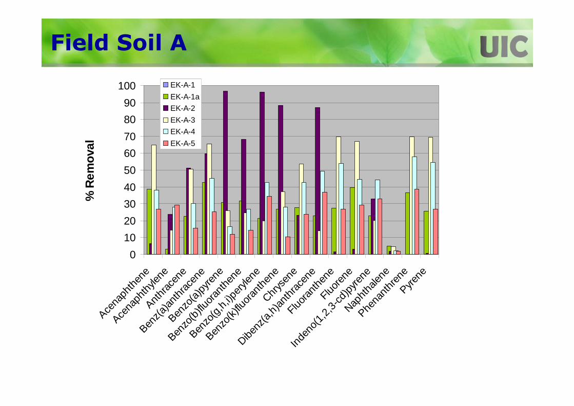
Field Soil A
0
10
20
30
40
50
60
70
80
90
100
Acena
phth
ene
Acena
phth
ylene
Anthr
acen
e
Benz(a
)ant
hrac
ene
Benzo
(a)p
yrene
Benzo
(b)flu
oran
then
e
Benzo
(g,h
,i)per
ylene
Benzo
(k)flu
oran
then
eChr
ysen
e
Dibenz
(a,h
)ant
hrac
ene
Fluora
nthe
neFluo
rene
Inde
no(1
,2,3
-cd)p
yrene
Napht
halen
e
Phena
nthr
ene
Pyrene
% R
emov
alEK-A-1
EK-A-1a
EK-A-2
EK-A-3
EK-A-4
EK-A-5

Field Soil B
EK-B-1 Toxic Contaminant Distribution
0
500
1000
1500
2000
2500
3000
3500
Lead Mercury
Co
nta
min
ant
con
cen
trat
ion
(m
g/k
g)
S-1 (Near Anode)
S-2 (Middle)
S-3 (Near Cathode)
EK-B-2 Toxic Contaminant Distribution
0
200
400
600
800
1000
1200
Lead MercuryC
on
tam
inan
t C
on
cen
trat
ion
(m
g/k
g)
S-1 (Near Anode)
S-2 (Middle)
S-3 (Near Cathode)
• EK-B-3 and EK-B-4 were not effective in contaminant removal
0.2M EDTA, 2VDC/cm 0.2M KI, 2VDC/cm
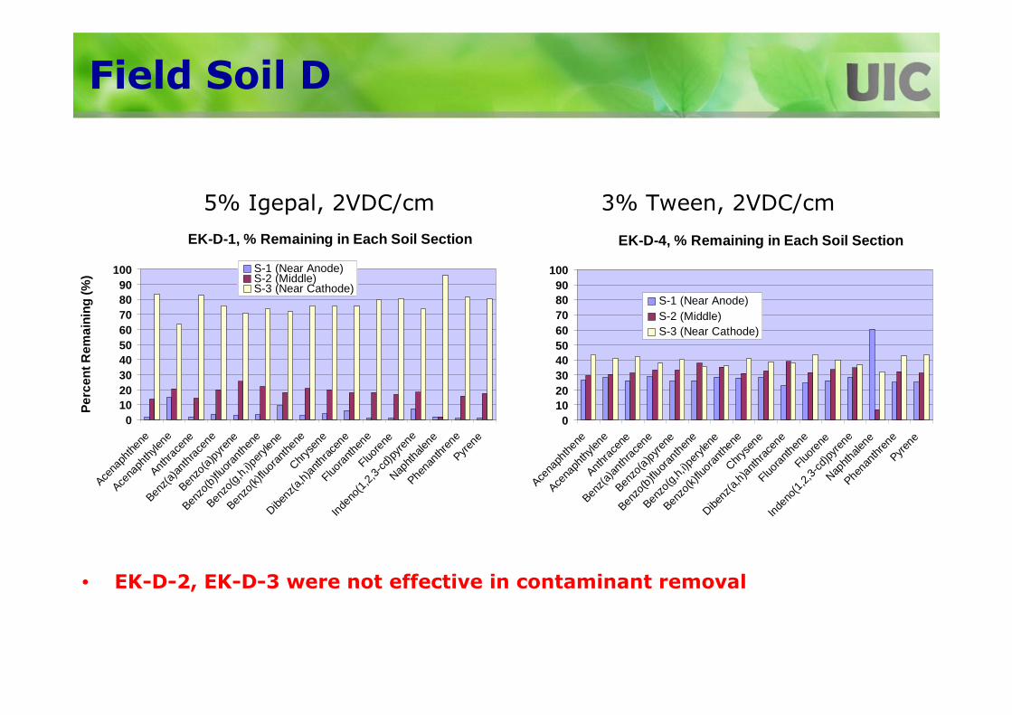
Field Soil D
EK-D-1, % Remaining in Each Soil Section
0102030405060708090
100
Acena
phthe
ne
Acena
phth
ylene
Anthr
acen
e
Benz(
a)an
thra
cene
Benzo
(a)p
yren
e
Benzo
(b)fl
uora
nthe
ne
Benzo
(g,h,
i)per
ylene
Benzo
(k)flu
oran
then
eChr
ysen
e
Dibenz
(a,h
)anth
race
ne
Fluora
nthe
neFluo
rene
Inde
no(1
,2,3-
cd)p
yren
e
Naphth
alene
Phena
nthr
ene
Pyren
e
Per
cen
t Rem
aini
ng (%
) S-1 (Near Anode)S-2 (Middle)S-3 (Near Cathode)
EK-D-4, % Remaining in Each Soil Section
0102030405060708090
100
Acena
phth
ene
Acena
phth
ylene
Anthr
acen
e
Benz(
a)an
thra
cene
Benzo
(a)p
yren
e
Benzo
(b)fl
uora
nthe
ne
Benzo
(g,h,
i)per
ylene
Benzo
(k)flu
oran
then
eChr
ysen
e
Dibenz
(a,h
)anth
race
ne
Fluora
nthen
eFluo
rene
Inde
no(1
,2,3-
cd)p
yren
e
Naphth
alene
Phena
nthr
ene
Pyren
e
S-1 (Near Anode)S-2 (Middle)S-3 (Near Cathode)
• EK-D-2, EK-D-3 were not effective in contaminant removal
5% Igepal, 2VDC/cm 3% Tween, 2VDC/cm
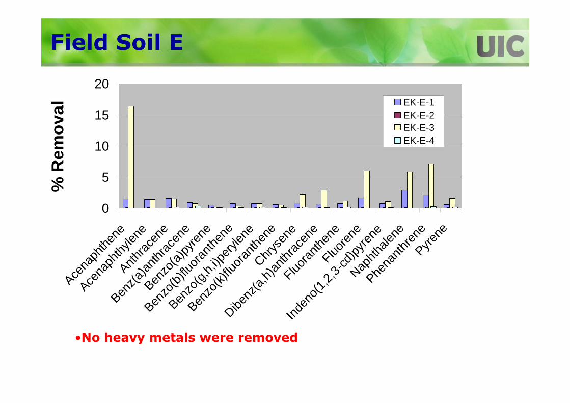
Field Soil E
0
5
10
15
20
Acena
phth
ene
Acena
phth
ylene
Anthr
acen
e
Benz(
a)an
thra
cene
Benzo
(a)p
yren
e
Benzo
(b)fl
uora
nthe
ne
Benzo
(g,h,
i)per
ylene
Benzo
(k)fl
uora
nthe
neChr
ysen
e
Dibenz
(a,h
)ant
hrac
ene
Fluora
nthen
eFluo
rene
Inde
no(1
,2,3
-cd)
pyre
ne
Napht
halen
e
Phena
nthr
ene
Pyren
e
% R
emo
val EK-E-1
EK-E-2EK-E-3EK-E-4
•No heavy metals were removed

So, how reliable is this technology?

Practical Issues/Considerations
1. Reliability of the technology
2. Costs of application
3. Practicality of implementation
4. Application of and ability to meet risk-based remediation goals
5. Anticipated remediation time
6. Acceptability to project stakeholders
7. Necessity of special permits
8. Implications on end-use of the site
9. Sustainability considerations, including triple bottom line parameters
10.Remediation versus management paradigm for complex sites

Costs of Application
• Costs depend on:– Zone of contamination (area and depth), type of
contaminants, and type of soils– Initial and target contaminant concentrations– Electrode wells & electrodes and their installation – Electrode conditioning solutions– Electricity consumption– Effluent treatment– Operation and monitoring– Site preparation and permits
• Actual costs unknown, estimated to be:– $20 to $225/yd3, but generally more than $60/yd3
– Very deep sources (>40 ft) and very small sites (<0.1 acres) usually cost more whereas larger, shallower sites cost less.
• Bottom line is that the costs have to be lowered.

Costs of Application
• Large scale EK systems should be simple to be competitive.
• Extensive electrode fluid management:
– expensive
– high operating costs
– greater chance of failure.
• Manage the cathode and anode fluids as passively as possible.

So, what is the cost of using this technology?

Practical Considerations
1. Reliability of the technology
2. Costs of application
3. Practicality of implementation
4. Application of and ability to meet risk-based remediation goals
5. Anticipated remediation time
6. Acceptability to project stakeholders
7. Necessity of special permits
8. Implications on end-use of the site
9. Sustainability considerations, including triple bottom line parameters
10.Remediation versus management paradigm for complex sites.

Electro-reclamation at Loppersum
� Year 1989
� Volume 250 m³
� Type of contamination
� As in heavy clay
� Concentration at start
� Max. 500 mg/kg
� Average 115 mg/kg
� Concentration at end
� Max. 29 mg/kg
� Average 10 mg/kg
� Energy 150 kW/ton
� Duration
� 80 days of 18 hours
� Product removed
� 38 kg As by ER
� 14 kg As by excavation
(Lageman, 2003)

Electro-reclamation at Stadskanaal
� Year 1990-1992
� Volume 2500 m³
� Type of contamination
� Cd in fine clayey sand
� Concentration at start
� Cd >2000 mg/kg
� Average 250 mg/kg
� Concentration at end
� Cd 5-40 mg/kg
� Average 11 mg/kg
� Energy 200 kW/ton
� Duration
� 2 ½ years(Lageman, 2003)
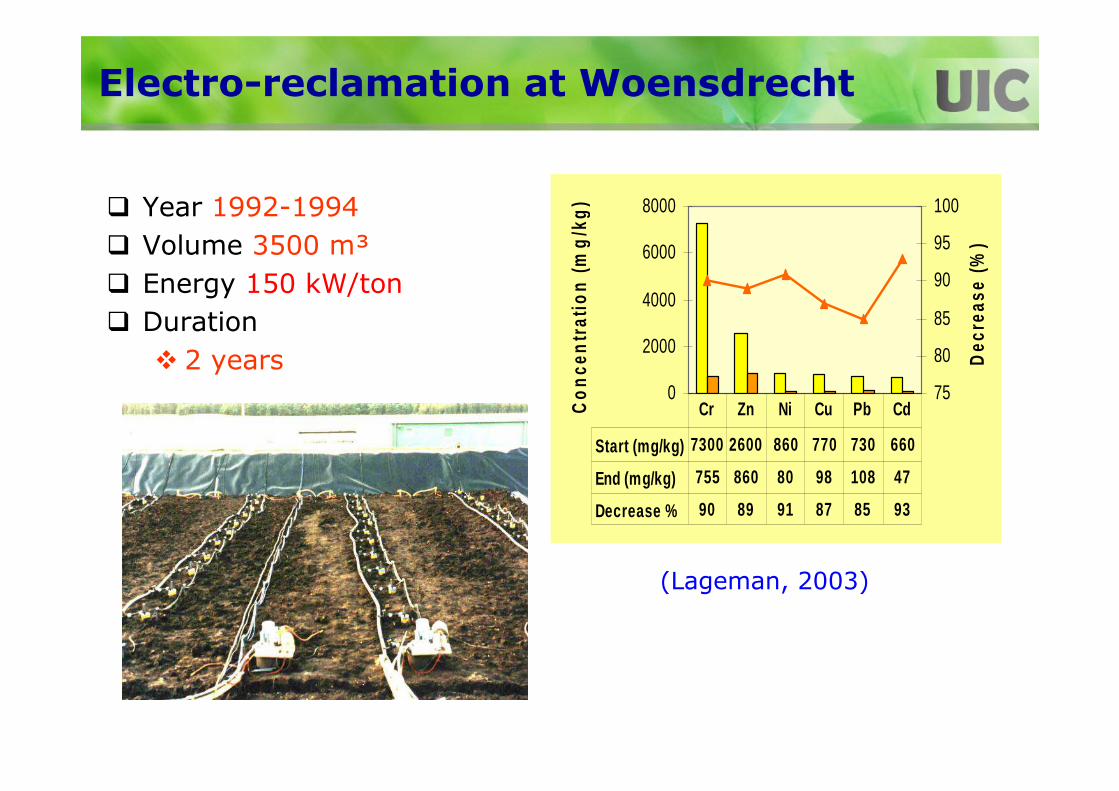
Electro-reclamation at Woensdrecht
� Year 1992-1994
� Volume 3500 m³
� Energy 150 kW/ton
� Duration
� 2 years
(Lageman, 2003)
0
2000
4000
6000
8000
Co
nce
ntr
atio
n (
mg
/kg
)
75
80
85
90
95
100
Dec
reas
e (%
)
Start (mg/kg) 7300 2600 860 770 730 660
End (mg/kg) 755 860 80 98 108 47
Decrease % 90 89 91 87 85 93
Cr Zn Ni Cu Pb Cd

EK: LasagnaTM Process
(Athmer, 2004)
LasagnaTM is the patented and trademarked name for the integration of DC electricity and in-situ treatment and was developed by a consortium of scientists from DuPont, General Electric and Monsanto along with the USEPA and US DOE.

Installation of Electrodes
Lasagna™ system installation was extremely successful in reducing TCE contamination at sites in the USA

EK: LasagnaTM Process
• DOE Facility, Paducah, KY
• TCE stored in a lined pit and used for testing of uranium storage steel cylinders
• TCE leaked and contaminated subsoil
• Clayey soil, K=1x10⁻⁶
cm/s
• Contaminated zone:90’x70’x40’
• Max TCE conc. 1500 mg/kg
(Athmer, 2004)

EK: LasagnaTM Process
• Electrodes and treatment zones installed with hollow mandrel systems
• Steel plate electrodes at 45’ spacing
• Treatment zones (1-inch thick) at 5’ spacing (iron filings)
• Powered 415-220 volts, depending on temperature increase (50 to 900C)
• EO flow at 0.5 cm/day, recycled, 1.6 pore volumes
(Athmer, 2004)
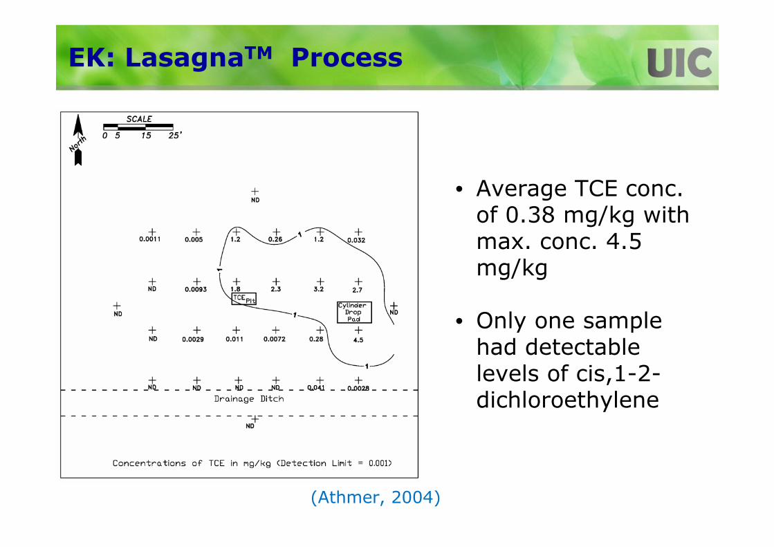
EK: LasagnaTM Process
• Average TCE conc. of 0.38 mg/kg with max. conc. 4.5 mg/kg
• Only one sample had detectable levels of cis,1-2-dichloroethylene
(Athmer, 2004)

e-Barrier
(Sale et al., 2005)

Bench-scale Study
TCE as a function of position (20 V). Position 0 is the center of the electrode pack.
(Sale et al., 2005)

Composite Panel Detail
(Sale et al., 2005)

Construction
Initial topsoil removal
Excavation priorto trench box installation
Electrode panel components Lifting of nine linked e-barrier modules (panels) prior to placement in trench
(Sale et al., 2005)

Construction
Placement of eight linked e-barrier modules into the trench linking with in-place ebarrier modules
Backfilling of trench with imported soil. Note risers containing electrical connections, gas vests, washout tubing and multilevel sampling bundles
Top of risers prior to surface completion Surface completion(Sale et al., 2005)

Lessons Learned
• Sustained TCE flux reduction up to 95%
• No adverse reaction intermediates
• Cost comparable to other technologies (e.g. ZVI PRB)
• Limitations:– Deep installation– Scale formation in high TDS waters– Flux reduction may be insufficient to meet the regulatory
groundwater concentration requirement

Practicality of Implementation
• Useful for small, source zones
• Very limited full-scale applications in the USA!
– LasagnaTM process is well documented!
• Incomplete technology developers’ information on pilot or full-scale field applications
• Lack of well documented case studies (detailed design, performance data and cost)
• No guidance on designing full-scale systems

Practicality of Implementation
• Well based electrodes may not be efficient– significant reduction in electrical current passage and voltage
drop due to open area.
• Larger planar electrodes are easier to install than well based electrode– no waste soil to manage
• EK systems should be coupled with in-situ destruction techniques
– ZVI barrier walls placed in the flow path works well (LasagnaTM)
– Enhanced bio shows promise
– Electrolytic barrier
So, how practical is to implement this technology?

Practical Issues/Considerations
1. Reliability of the technology
2. Costs of application
3. Practicality of implementation
4. Application of and ability to meet risk-based remediation goals
5. Anticipated remediation time
6. Acceptability to project stakeholders
7. Necessity of special permits
8. Implications on end-use of the site
9. Sustainability considerations, including triple bottom line parameters
10.Remediation versus management paradigm for complex sites

Pre-Risk Era (Early 80s)
• Remediation goals often set to “pristine”condition/restoration
• Proved to be cost and time prohibitive

Emergence of Risk Era
‣ National Research Council/National Academy of Sciences (NRC/NAS)
‣ RED BOOK (1983) Risk Assessment in the Federal Government: Managing the Process
• Addressed health risk assessments across all Federal Agencies
• Defined four-step risk assessment process
• Steps used in several EPA statutes but with different methods (e.g., RCRA, CERCLA, FIFRA, TSCA)
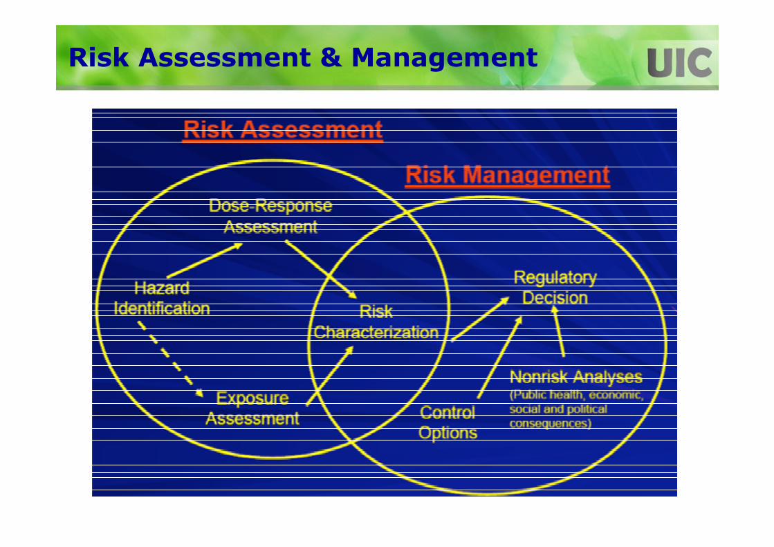
Risk Assessment & Management

Risk Characterization
• Likelihood of injury, disease, or death resulting from exposure to a potential environmental hazard
• Cancer Risk Equation
• Cancer Risk = ADD x CSF– Risk = incremental probability of an individual developing cancer from
exposure– ADD = chronic lifetime daily dose averaged over 70 years– CSF = cancer slope (or potency) factor
• Noncancer Risk Equation
• Hazard Quotient = ADD/RfD– ADD = average daily dose (or intake)– RfD = reference dose– HI > 1 – potentially of health concern
• Address uncertainty and variability
• Assumes risk additive over all chemicals in mixture

Risk-based Screening & Corrective Levels
• Calculate allowable concentrations in media based on allowable risk - inverse of USEPA approach
• Risk-based Corrective Action (RBCA) for Petroleum Release Sites
– ASTM E1739– Tiered Approach
• States - examples• Illinois: Tiered Approach to Corrective Action Objectives
(TACO)- IAC 620• California:
» Department of Toxic Substances Control (DTSC) – California Human Health Screening Levels (CHHSLs)
» San Francisco Bay Regional Water Quality Control Board (RWQCB) –Environmental Screening Levels (ESLs)
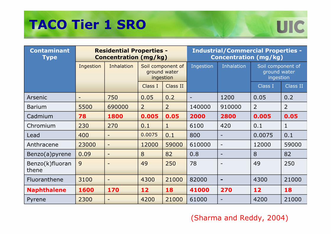
Contaminant Type
Residential Properties -Concentration (mg/kg)
Industrial/Commercial Properties -Concentration (mg/kg)
Ingestion Inhalation Soil component of ground water
ingestion
Ingestion Inhalation Soil component of ground water
ingestion
Class I Class II Class I Class II
Arsenic - 750 0.05 0.2 - 1200 0.05 0.2
Barium 5500 690000 2 2 140000 910000 2 2
Cadmium 78 1800 0.005 0.05 2000 2800 0.005 0.05
Chromium 230 270 0.1 1 6100 420 0.1 1
Lead 400 - 0.0075 0.1 800 - 0.0075 0.1
Anthracene 23000 - 12000 59000 610000 - 12000 59000
Benzo(a)pyrene 0.09 - 8 82 0.8 - 8 82
Benzo(k)fluoranthene
9 - 49 250 78 - 49 250
Fluoranthene 3100 - 4300 21000 82000 - 4300 21000
Naphthalene 1600 170 12 18 41000 270 12 18
Pyrene 2300 - 4200 21000 61000 - 4200 21000
TACO Tier 1 SRO
(Sharma and Reddy, 2004)

How are treatment target concentrations decided?

Practical Issues/Considerations
1. Reliability of the technology
2. Costs of application
3. Practicality of implementation
4. Application of and ability to meet risk-based remediation goals
5. Anticipated remediation time
6. Acceptability to project stakeholders
7. Necessity of special permits
8. Implications on end-use of the site
9. Sustainability considerations, including triple bottom line parameters
10.Remediation versus management paradigm for complex sites.

Anticipated Remediation Time
• No reliable way to estimate remediation time
– Limited modeling studies
• Depends on the site area/depth, contamination, and EK system design/operation
• Case studies
– Lageman (1989-94)• Heavy Metal Site 1: 80 days
• Heavy Metal Site 2: 2.5 years
• Heavy Metal Site 3: 2 years
– Athmer (2004)• TCE Site 1: 2 years
• TCE Site 2: 2.5 years
– Sale et al. (2005)• TCE Site: 1.5 years

How can we estimate cleanup time?

Practical Considerations
1. Reliability of the technology
2. Costs of application
3. Practicality of implementation
4. Application of and ability to meet risk-based remediation goals
5. Anticipated remediation time
6. Acceptability to project stakeholders
7. Necessity of special permits
8. Implications on end-use of the site
9. Sustainability considerations, including triple bottom line parameters
10.Remediation versus management paradigm for complex sites
Stakeholder Acceptability
• Stakeholders
– Owner, consultant, regulators/government, community/public
• Effects on underground utilities and liabilities

Practical Considerations
1. Reliability of the technology
2. Costs of application
3. Practicality of implementation
4. Application of and ability to meet risk-based remediation goals
5. Anticipated remediation time
6. Acceptability to project stakeholders
7. Necessity of special permits
8. Implications on end-use of the site
9. Sustainability considerations, including triple bottom line parameters
10.Remediation versus management paradigm for complex sites

Special Permits
• Injection of electrode conditioning solutions
– Toxicity data
– Fate of residual in subsurface
• Compatibility of electrodes with subsurface
• Effluent management and treatment
– Treatment
– Discharge permits (e.g., NPDES)

Practical Considerations
1. Reliability of the technology
2. Costs of application
3. Practicality of implementation
4. Application of and ability to meet risk-based remediation goals
5. Anticipated remediation time
6. Acceptability to project stakeholders
7. Necessity of special permits
8. Implications on end-use of the site
9. Sustainability considerations, including triple bottom line parameters
10.Remediation versus management paradigm for complex sites

End-use of the Site
• What will be the end-use of the site?– Residential
– Commercial
– Agricultural
– Nature preserve
• End-use affects the remediation goals (based on human and ecological risks)
• Physical, mineralogical, chemical and biological changes in subsurface due to EK
– Extreme final pH, depletion of nutrients,…
• Will the treated soil suitable as:– Construction material/support (strength, compressibility,
hydraulic conductivity,…)
– Agricultural land (nutrients, crop growth,…)
– Habitat

Practical Considerations
1. Reliability of the technology
2. Costs of application
3. Practicality of implementation
4. Application of and ability to meet risk-based remediation goals
5. Anticipated remediation time
6. Acceptability to project stakeholders
7. Necessity of special permits
8. Implications on end-use of the site
9. Sustainability considerations, including triple bottom line parameters
10.Remediation versus management paradigm for complex sites

Sustainability
� Presidents’ Executive Orders� 13123-Greening the Government through
Efficient Energy Management (6/1999)
� 13514-Federal Leadership in Environmental, Energy, and Economic Performance (10/2009)
� 2011 NRC Green Book� Recommends EPA to formally adopt
sustainability approach
� Framework for EPA Sustainability Decisions
� Theme – “Cleanup based on holistic approach (triple bottom line)”

Green and Sustainable Remediation
Definition“the site-specific use of products, processes, technologies, and procedures that mitigate contaminant risk to receptors while balancing community goals, economicimpacts, and netenvironmental effects”
(ITRC, ASTM)

Core Elements of Green Remediation
“Reduction, Efficiency,
and Renewables…”
“Protect Air Quality; Reduce
Greenhouse Gases…”
“Minimize, Reuse, and Recycle…”
“Conserve, Protect,
and Restore…”
“Improve Quality; Decrease Quantity of Use…”
(USEPA)

Triple Bottom Line/Sustainable Design

Sustainability/LCA-based Design
• Electrode Choice
• Electrode Conditioning Solutions Choice
• Energy Source/Consumption
• Water Consumption
• Waste/Effluent Generated
• Direct and Indirect Economic Benefits
• Community Acceptance/Benefits
Net broader impacts?

Electrodes: LCA Results
Electrode Types
Titanium Iron Graphite Carbon
Impa
cts,
mP
t
0
100
200
300
400
500
Carcinogens Resp. organics Resp. inorganics Climate change Radiation Ozone layer Ecotoxicity Acidification/ Eutrophication Land use Minerals Fossil fuels

Electrode Solutions: LCA Results
Electrode Solutions
Solvent EDTA DTPA Citric Acid Acetic Acid
Impa
cts,
mP
t
0
100
200
300
400
500
600 Carcinogens Resp. organics Resp. inorganics Climate change Radiation Ozone layer Ecotoxicity Acidification/ Eutrophication Land use Minerals Fossil fuels

Practical Considerations
1. Reliability of the technology
2. Costs of application
3. Practicality of implementation
4. Application of and ability to meet risk-based remediation goals
5. Anticipated remediation time
6. Acceptability to project stakeholders
7. Necessity of special permits
8. Implications on end-use of the site
9. Sustainability considerations, including triple bottom line parameters
10.Remediation versus management paradigm for complex sites

Management vs Remediation Paradigm for Complex Sites
• NRC report published in 2013
Complex Sites• Fractured media• Very large plumes• Radioactive contaminants• Very deep contamination• Fine-grained units

Complex Sites
Passive Long-termManagement Option MNA, NA, permeable reactive barrier, orphysical containment
Active Long-term Management Option•Community outreach program•Contaminant monitoring plan •Institutional and engineering controls

Final Remarks
Electrokinetic remediation by itself or with enhancements may be ineffective and/or costly
Integrated electrokinetic/electrochemical remediation technologies have great potential to be effective and practical•Potential to design green and sustainable systems (use DC solar power supply, in-situ degradation, metal recovery & reuse)
Ideally suited for:•Remediation of low permeability/heterogeneous subsurface•Source zone remediation•Difficult contaminants, including the contaminant mixtures
1
2
3

Final Remarks
Provides greater flexibility to adapt at any time during the remediation process to changing or different contaminant conditions, without the need for major changes in the field setup
Many studies investigated the fundamental aspects of electrokinetic remediation, but very limited studies address the practical issues to successfully implement the technology at actual contaminated sites-Need more use-inspired basic research/applied research
4
5

Take Away Message
1. Reliability of the technology
2. Costs of application
3. Practicality of implementation
4. Application of and ability to meet risk-based remediation goals
5. Anticipated remediation time
6. Acceptability to project stakeholders
7. Necessity of special permits
8. Implications on end-use of the site
9. Sustainability considerations, including triple bottom line parameters
10. Remediation versus management paradigm for complex sites
As we do our research, let’s keep the following practical considerations in mind:

Acknowledgements
• Funding
• Graduate Students
– R. Saichek
– S. Chinthamreddy
– K. Maturi
– A. Al-Hamdan
– K. Darko-Kagya
• Related Publications
www.uic.edu/labs/geotech

Thanks!
Questions & Answers