new applications of super-resolution in medical...
TRANSCRIPT

1
New Applications of Super-resolution inMedical Imaging
M. Dirk Robinson
Ricoh Innovations Inc., Menlo Park, CA, USA
Stephanie J. Chiu, Cynthia A. Toth
Duke University, Durham, NC, USA
Joseph A. Izatt, Joseph Y. Lo
Duke University, Durham, NC, USA
Sina Farsiu
Duke University, Durham, NC, USA
CONTENTS1.1 Introduction . . . . . . . . . . . . . . . . . . . . . . . . . . . . . . . . . . . . . . . . . . . . . . . . . . . . . . . . . . . . . . . 21.2 The Super-Resolution Framework . . . . . . . . . . . . . . . . . . . . . . . . . . . . . . . . . . . . . . . . 3
1.2.1 Image Capture Model . . . . . . . . . . . . . . . . . . . . . . . . . . . . . . . . . . . . . . . . . . . . . 31.2.2 Super-Resolution Estimation Framework . . . . . . . . . . . . . . . . . . . . . . . . . 4
1.3 New Medical Imaging Applications . . . . . . . . . . . . . . . . . . . . . . . . . . . . . . . . . . . . . . . 61.3.1 Super-Resolution in Low Radiation Digital X-ray Mammography 6
1.3.1.1 Multiframe Shift Estimation . . . . . . . . . . . . . . . . . . . . . . . . . . . . . 71.3.1.2 Multiframe ForWarD Deconvolution and Denoising . . . . 101.3.1.3 Experimental X-ray Results . . . . . . . . . . . . . . . . . . . . . . . . . . . . . 12
1.3.2 Super-Resolution in Optical Coherence Tomography . . . . . . . . . . . . . 151.3.2.1 Proposed Method: Sparse Repeated Imaging . . . . . . . . . . . 161.3.2.2 Multiframe Joint Registration . . . . . . . . . . . . . . . . . . . . . . . . . . . 191.3.2.3 Experimental Results . . . . . . . . . . . . . . . . . . . . . . . . . . . . . . . . . . . . 21
1.4 Conclusion . . . . . . . . . . . . . . . . . . . . . . . . . . . . . . . . . . . . . . . . . . . . . . . . . . . . . . . . . . . . . . . . . 221.5 Acknowledgment . . . . . . . . . . . . . . . . . . . . . . . . . . . . . . . . . . . . . . . . . . . . . . . . . . . . . . . . . . 23
The image processing algorithms collectively known as super-resolution haveproven effective in producing high-quality imagery from a collection of low-resolution photographic images. In this chapter, we examine some of the ad-vantages and challenges of applying the super-resolution framework to ap-plications in medical imaging. We describe two novel applications in detail.The first application addresses the problem of improving the quality of digitalmammography imaging systems while reducing X-ray radiation exposure. The
1

2 Digital Imaging and Computer Vision
second application addresses the problem of improving the spatio-temporalresolution of spectral domain optical coherence tomography systems in thepresence of uncontrollable patient motion. Experimental results on real datasets confirm the effectiveness of the proposed methodologies.
1.1 Introduction
The invention of the charge coupled device (CCD) created a new era of imagingwherein optical images could be efficiently captured by an array of solid-statedetectors and stored as digital information. The resolution of the capturedimage depended on the size and number of these detectors. Most imagingapplications critically depend on high-resolution imagery. Increasing resolu-tion by improving detector array resolution is not always a feasible approachto improving resolution. For example, while improvements in semiconductormanufacturing have translated into higher-resolution image sensors, shrink-ing pixel sizes has a tendency to decrease signal-to-noise ratios (SNR) andlight sensitivity. Furthermore, practical cost and physical limitations limitthe ability to change detectors for most legacy imaging systems. To addressthis issue, the image processing community is developing a collection of algo-rithms known as super-resolution for generating high-resolution imagery fromsystems having lower-resolution imaging detectors. These algorithms combinea collection of low-resolution images containing aliasing artifacts and restorea high-resolution image. The ability to transcend the fundamental resolu-tion limits of sensors using super-resolution algorithms has shown significantprogress and capability in the area of photographic imaging. By far, the major-ity of applications using super-resolution technology have been in the area ofphotographic imagery for either consumer or defense-type applications, whichare discussed in the other chapters of this book.
Relatively recently, researchers have begun developing methods to ex-tend the super-resolution framework to different medical imaging applications.Medical imaging applications differ from photographic imaging in several keyrespects. First, unlike photographic imaging, medical imaging applications of-ten use highly controlled illumination of the human subject during image ac-quisition. As with any imaging system, stronger illumination energy results inhigher signal-to-noise ratios. In the case of medical imaging, however, illumi-nation radiation is limited to prevent tissue damage, thereby limiting the SNRto well below that of photographic imaging. Second, imaging speed is moreimportant in medical imaging applications than in photographic applications.Short acquisition times both limit patient discomfort and minimize imagingartifacts associated with patient movement. Third, unlike photographic imag-ing, the goal of medical imaging is to facilitate the detection or diagnosisof disease, rather than produce visually pleasing imagery. Consequently, im-
New Applications of Super-resolution in Medical Imaging 3
age processing artifacts are much less tolerable in medical images than inphotographic applications. Luckily, medical imaging systems operate underhighly controlled environments with highly similar objects. Algorithm devel-opers can leverage prior knowledge about the anatomy or biology to improveimage quality. Finally, the majority of medical imaging applications involvecreating images from radiation propagation through three-dimensional ob-jects. Thus, while the final images are two-dimensional, they represent someform of projection through a three-dimensional volume.
In this chapter, we describe super-resolution and its applications from themedical imaging community’s point of view. In Section 1.2, we describe thegeneral super-resolution framework and provide a brief review of the differ-ent super-resolution algorithms. In Section 1.3.1, we introduce the first oftwo novel applications of super-resolution in medical imaging. Namely, we de-scribe how we tailor the super-resolution framework to improve the resolutionfor digital X-ray mammography. In Section 1.3.2, we describe how we applythe super-resolution framework to Optical Coherence Tomography (OCT). Fi-nally, we conclude in Section 1.4 with some thoughts about future applicationsof super-resolution in medical imaging.
1.2 The Super-Resolution Framework
The goal of super-resolution image processing is to extract a high-resolutionimage from a collection of images containing aliasing artifacts. When a collec-tion of aliased, low-resolution images contains sufficient variation, the high-resolution, aliased image content can be separated from the low-resolutionimage content thereby increasing the image resolution. This type of super-resolution is not to be confused with optical methods for transcending theoptical diffraction limit (e.g. [63]). There are a number of broad reviews ofsuper-resolution algorithms [3, 15, 35]. In this section, we describe the generalsuper-resolution imaging framework. The section begins with a description ofa generic image capture model and concludes with a general super-resolutionestimation framework.
1.2.1 Image Capture Model
The image capture model describes the various physical processes involvedwhen capturing a set of images. As with most multiframe image super-resolution algorithms, the collection of images must contain relative motionbetween the sets of images from which resolution is enhanced. We assume verysimple translational motion for several reasons. First, even if this motion isnot appropriate in a wide-field sense, the motion model is typically accuratefor local regions within the images [1]. Second, the imaging acquisition system

4 Digital Imaging and Computer Vision
can often be controlled to induce only translational motion in the capturedimages. Thus, for the remainder of this chapter, bear in mind that when werefer to an image, we could also be referring to a cropped portion of a largerimage. This model has been used in several previous works on super-resolution[11, 16, 23, 32].
The general image capture model, or forward model, combines the variouseffects of the digital image acquisition process such as point-wise blurring,motion, undersampling, and measurement noise. We represent the forwardimaging model using matrix notation as
yk = DHS(vk)x + ek, (1.1)
where x and y are rearranged in lexicographic order. Here, the vector yk rep-resents B×B (assumed square without loss of generality) samples of the cap-tured image yk(m′
1, m′2), where m′
1, m′2 ∈ [0, B− 1], are ordered as a (B)2× 1
vector. The captured image is undersampled with respect to an unknownhigh-resolution image x(m1,m2), where mi ∈ [0, DiB − 1], by a factor of D1
and D2 in each of the two respective dimensions. The vector x representssamples of the unknown D1B × D2B high-resolution image tile x(m1, m2)similarly ordered. The warping operator S(vk) of size D1D2B
2 × D1D2B2
represents the subpixel spatial shifts between the captured images. Withoutloss of generality, we assume that the image y0 defines the coordinate systemof the high-resolution image and hence we only have to estimate the unknownmotion parameters for the remaining K images. Note that, here to simplifynotations, instead of vk,0, we use vk = [vk1 , vk2 ], which is the spatial shift-ing between the reference frame (0th) and the kth frame. In Section 1.3.2,however, we will use the full form of vk,i to represent the motion betweenthe ith and kth frames. In our model, we assume that these spatial shifts arecontinuous values in the range of [−Di, Di]. This corresponds to the rangeof subpixel motion in the captured images. The downsampling operator D ofsize B2 × D1D2B
2 captures the undersampling of the detector. The matrixH represents the blurring associated with the imaging system. This blurringcould be the result of multiple processes within the imaging system. For exam-ple, this blurring could be the result of integration apertures or motion duringthe image capture, or scattering of radiation in the object medium as a pointspread function (PSF). For the time being, we will assume that this can bereliably measured or estimated from some other process (note [39] as an exam-ple of jointly estimating the high-resolution image and the blur parameters ina Bayesian framework). Finally, ek of size B2×1 represents the noise inherentin the analog-to-digital conversion. For our purposes, we assume this noise tobe uncorrelated, zero-mean noise with standard deviation σ. This model issufficiently broad as to cover a wide variety of imaging systems.

New Applications of Super-resolution in Medical Imaging 5
1.2.2 Super-Resolution Estimation Framework
The goal of super-resolution image processing is to estimate the high-resolution image x from the set of captured images yk. The most commonestimation framework begins with a cost function or penalty function relatingthe observed data to the unknown high-resolution image. The most commonstatistical framework found in super-resolution is that of the maximum a pos-teriori (MAP) penalty function of the form
Ω(x, vk) = Ωd(x, vk) + Ωp(x). (1.2)
The MAP functionals are based on the construction of a cost function(Ω), which is the summation of two distinct terms. One is the data penaltyterm Ωd, which measures the closeness of data to the estimates. The otheris the regularization term Ωp, which applies the prior information about orconstraints on the unknown high-resolution image (x).
Early MAP functionals used in super-resolution processing utilized simplequadratic data penalty and regularization terms [10, 45]. The most commonlyemployed regularization terms use Tikhonov type functionals despite theirtendencies to reduce edge contrast. These quadratic regularization functionalspenalize the amount of high spatial-frequency energy in the high-resolutionimage estimate. For example, using the generic imaging model of Equation(1.1), a typical quadratic MAP functional takes the form
Ω(x, vk) =K∑
k=0
‖yk −DHS(vk)x‖2 + λxT C−1x x, (1.3)
where C−1x is often a spatial high-pass operator and λ is the weighting scalar.
When Cx is the exact covariance of the unknown high-resolution image, thenthis cost function produces the ideal Wiener filter estimate of the unknownimage. This MAP functional has the advantage of being quadratic, whichmeans that the penalty function has an analytic solution that is a linearfunction of the input measurements.
Through the years, application of more advanced prior functions Ωp suchas Adaptive Kernel regression [53] and Bilateral Total-Variation (B-TV) [16]have produced higher quality estimates of the final by imposing more accurateassumptions about the image content. The tradeoff, however, is that suchnon-linear prior functionals are more expensive to evaluate and require morecomputationally-complex iterative minimization techniques. For example, theB-TV cost function is defined as
ΩB-TV(x, vk) =K∑
k=0
‖yk −DHS(vk)x‖22 + λ
L∑
t1,t2=−L
%|t1|+|t2|‖x− S(t)x‖1,(1.4)
where t = [t1, t2] is a set of integer pixel shifts and 0 < % ≤ 1 is a constant

6 Digital Imaging and Computer Vision
[16]. Such non-quadratic functionals can, however, preserve many importantfeatures of images such as edges. Also, MAP-based robust super-resolutiontechniques (e.g. [9, 16, 36]) are able to reduce the effect of outliers such asmotion estimation error.
Both the quadratic and non-quadratic MAP functionals require knowledgeof the relative shifts between the collection of low-resolution images. When theSNR is reasonably high and the amount of aliasing artifacts are low, then theshifting parameters vk can be reasonably estimated in an initial step fromthe captured images yk. Theory as well as experimental evidence, however,suggests that using a separate shift estimation process in low-SNR cases issuboptimal. Therefore, the critical issue of joint super-resolution and motionestimation problem has been the topic of several papers (e.g. [2, 24, 43, 58,59, 62]). Note that, additional priors on motion vector distribution may bealso added to the above cost function [24].
1.3 New Medical Imaging Applications
Early, fast, and accurate detection of imaging biomarkers of the onset andprogression of diseases is of great importance to the medical community sinceearly detection and intervention often results in optimal treatment and re-covery. The advent of novel imaging systems has for the first time enabledclinicians and medical researchers to visualize the anatomical substructures,pathology, and functional features in vivo. However, earlier biomarkers of dis-ease onset are often critically smaller or weaker in contrast compared to theircorresponding features in the advanced stages of disease. Therefore, medicalimaging community strives for inventing higher-resolution/contrast imagingsystems. As noted in Section 1.2, super-resolution can be beneficial in im-proving the image quality of many medical imaging systems without the needfor significant hardware alternation.
An excellent review of previous medical imaging applications of super-resolution is given in [20]. We refer the interested reader to [20] for a broadreview of applications in magnetic resonance imaging (MRI) [21, 38], func-tional MRI (fMRI)[37], and positron emission tomography imaging system(PET)[29, 30]. In the following two sections, we explore novel applicationsof the super-resolution framework to medical imaging. The first applicationis in the area of X-ray digital mammography. The second is in the area ofOptical Coherence Tomography (OCT). Each application has its own uniqueproperties that demand customization of the general super-resolution frame-work described in the previous section. In both applications, the advantage ofapplying the super-resolution framework is achieved by special modificationof the standard image acquisition technique.

New Applications of Super-resolution in Medical Imaging 7
1.3.1 Super-Resolution in Low Radiation Digital X-rayMammography
Digital mammography provides the opportunity to efficiently control and cap-ture digital images of the breast, while exposing the patient to the minimumamount of radiation. Today’s digital detectors cannot shrink pixel sizes toincrease resolution without sacrificing the SNR measurement. To maximizeimage resolution, we have explored digitally combining multiple low-dosageimages, each containing spatial shifts. These shifts are the result of patientmovement, intentional dithering of the detector, vibration in the imaging sys-tem, and small movement of the imaging gantry. In practice, the motion con-tained in the captured images is a combination of all such sources necessitatingaccurate registration of the aliased, low-resolution images.
Applying super-resolution processing to X-ray imaging requires overcom-ing two challenges. The first is the large amount of data associated with digitalmammogram images. The captured low-resolution images could have as muchas 10 megapixels worth of data. Thus, computational efficiency is extremelyimportant during processing. Second, the total radiation exposure over the col-lection of images cannot exceed that of a normal X-ray image dosage. There-fore, the captured data has extremely low peak-SNR (PSNR). For example,Figure 1.1 compares a high-dosage X-ray image (computed PSNR1 ' 13 dB)with the very low exposure images (computed SNR ' 3 dB) used in ourmultiframe scheme.
Thus, providing high-resolution imagery requires sophisticated, nonlinearreconstruction techniques to address the extremely low SNR of the capturedimages. To address these two challenges, we apply a divide and conquer ap-proach to both improve efficiency while maximizing the denoising effectiveness.To achieve this, we propose a three-stage (registration, reconstruction, andrestoration) algorithm. The overall algorithm procedure is shown in Figure1.2. The entire algorithm operates on a tile-based fashion. The process beginsby finding a collection of tiles with approximately equal regions-of-interest.Then, each of these tiles are registered to a subpixel precision to estimate theshifts vk. Next, we apply a multiframe image restoration step with a weakquadratic prior function, resulting in a deblurred aliasing free image with re-construction artifacts with known statistics. Next, we perform a fast estimateof wavelet coefficients, which best match the reconstruction artifacts in theprevious step. Finally, we apply a nonlinear wavelet thresholding-based de-noising step, to recover an efficiently denoised super-resolved image. In whatfollows we describe each step in detail.
1In this work, the PSNR was computed numerically as PSNR= 20log10sn
. In experimentson real images s is the grayscale difference between the minimum and maximum signalregions and n is the noise standard deviation estimated from flat regions. In simulatedexperiments, n is the RMSE error between the estimated and ground truth image.

8 Digital Imaging and Computer Vision
(a)
(b) (c)
FIGURE 1.1Mammogram X-ray images from the phantom breast in (a). The red rectan-gular section in (a) is zoomed in (b) and (c). The high dosage image in (b) iscaptured at 226mAs (PSNR' 13dB). The extremely low-dosage image in (c)is captured at 11.3 milliAmpere-second (mAs) (PSNR' 3dB). Regardless ofSNR, both images show aliasing artifacts.

New Applications of Super-resolution in Medical Imaging 9
FIGURE 1.2The block diagram shows the non-iterative super-resolution algorithm we ap-ply to digital mammogram images.
1.3.1.1 Multiframe Shift Estimation
Apart from the basic block-matching required to find a collection of approxi-mately registered image tiles yk [41], the super-resolution algorithm beginswith a multiframe subpixel shift estimation algorithm. The efficiency of thisstage is improved by ignoring the optical blur. Considering the locally space-invariant PSF and shift assumptions in our models, we may reverse the orderof the shifting and blur operators in Equation (1.1) [11] and reformulate theforward model without the blur operator as
yk = DS(vk)z + ek, (1.5)
where z = Hx is the unknown high-resolution blurry image.

10 Digital Imaging and Computer Vision
The registration algorithm begins with a variant of the quadratic penaltyfunction of Equation (1.3). The optimization process then will be formulatedas
Ω1(z, vk) =K∑
k=0
‖yk −DS(vk)z‖22 + λzT C−1z z, (1.6)
where Cz is the covariance matrix of the unknown signal z, which is typicallyassumed to be stationary. In other words, we can ignore the optical blurfor this stage of processing. A typical solution to the above problem is thecyclic coordinate-descent method [24], in which in each iteration one unknownvariable is updated based on the estimate of the other unknown variable fromthe previous iteration.
Noting that Equation (1.6) is known in numerical analysis literature asthe Separable Non-linear Least Squares problem [18], we momentarily assumein our Variable-Projection technique [42, 58] that the non-linear parameters(motion-vectors) are known. Consequently, the estimate of the set of linearparameters (z) is computed as
z =(Q(vk) + λC−1
z
)−1g(vk), (1.7)
where
Q(vk) =1σ2
K∑
k=0
ST (vk)DT DS(vk), (1.8)
g(vk) =1σ2
K∑
k=0
ST (vk)DT yk . (1.9)
We plug the parametric estimate of the blurry high-resolution image (z)into the MAP functional (Eq. (1.6)) and after some algebraic simplifications,we get a new (maximization) cost function that only relies on the motion-vectors:
Ω1(vk) = g(vk)T(Q(vk) + λC−1
z
)−1g(vk). (1.10)
Note that, unlike the cyclic coordinate-descent method, we require no it-erations between the sets of parameters since we do not explicitly calculateEquation (1.7). Indeed, a direct approach to maximize Equation (1.10) in-volves inverting a large matrix of size D1D2B
2 ×D1D2B2 which is computa-
tionally challenging for even small image tiles. In [42], we described a seriesof numerical tricks to speed up the process. One is solving the problem in theFourier domain and taking advantage of the spectral folding phenomenon inaliased images.

New Applications of Super-resolution in Medical Imaging 11
1.3.1.2 Multiframe ForWarD Deconvolution and Denoising
The output of the previous algorithm is an estimate of the set of samplingshift offsets vk with which we can estimate the high-resolution image x.We estimate a high-quality super-resolution image using a non-iterative, two-stage, linear deconvolution and nonlinear denoising algorithm. The algorithmaddresses the SNR versus sharpness tradeoff inherent to quadratic-type reg-ularization functionals without resorting to iterative, nonlinear regularizationpenalty functions. More information about the algorithm can be found in [44].
The first stage of the algorithm performs multiframe deconvolution using aweak quadratic penalty function. Armed with estimates of the image shifts, asharpened, high-resolution image can be obtained using a variant of Equation(1.7) given by
x = B−1(v)HT g(v), (1.11)
where
B(v) = HT Q(v)H + λC−1x ,
(1.12)
v = [v1, ...,vk]T and Q and g were defined in Equations (1.8) and (1.9).In this first stage of the algorithm, we use a very small value of λ so
as to under-regularize the estimate of the high-resolution image estimate x.This creates a very sharp high-resolution image at the expense of extremenoise amplification. The second stage of the algorithm involves eliminatingthe noise while preserving the image signal content. We achieve this with atype of wavelet thresholding algorithm similar to the ForWard algorithm of[34] or the BayesShrink algorithm of [4]. The wavelet thresholding algorithmoperates by first applying a wavelet transform to the noisy high-resolutionimage represented as
w = Ψx, (1.13)
where the matrix Ψ represents the wavelet transform operator and w thewavelet coefficients. Then, the wavelet coefficients are scaled according to
w′i = sgn(wi)max(0, |wi| − γi), (1.14)
where wi represents the individual wavelet coefficients, sgn is the sign func-tion, and γi represents the threshold value for those wavelet coefficients. Af-ter applying this threshold, the inverse wavelet transform is applied to thethresholded wavelet coefficients to get the final denoised estimate of the high-resolution image
x = Ψ−1w′. (1.15)

12 Digital Imaging and Computer Vision
This type of wavelet thresholding has the ability to eliminate noise whilepreserving signal content. More information about how this is implementedefficiently can be found in [44].
1.3.1.3 Experimental X-ray Results
We applied our multiframe reconstruction and restoration algorithm to realimages captured on an experimental X-ray imaging system. Our experimentalimaging system is based on a Mammomat NovationTOMO digital mammog-raphy prototype system (Siemens Medical Solutions, Erlangen Germany)2,stationed at Duke University Medical Center. The system uses a stationaryselenium-based detector having 85 µm pixels. Pixels with this size correspondto a Nyquist sampling rate of 5.6 line pairs per millimeter (lp/mm). We used aCIRS model 11A breast phantom (CIRS Inc., Norfolk VA) to test our super-resolution algorithms. We introduced shifts in the image by two methods.First, we allowed the X-ray tube to rotate by ± 1 degree. Second, we manuallymoved the breast phantom to introduce motion into the system. This manualmotion was completely uncontrolled. Our dataset consisted of 15 frames at thelow dosage level of 11.3 mAs at 28 kVp tube voltage. As a point of reference,we also acquired a single frame at a more typical dosage of 226 mAs at 28kVp tube voltage (Fig. 1.1), which is 25.
The breast phantom includes several testing features including a pair ofresolution bar charts and small grains that mimic calcification in the breast.The results reported here are focused on the test resolution chart and thecalcification grains that best represent the contrast performance and potentialimproved-detection abilities of the multiframe image reconstruction system.
We applied our algorithm to 100 × 100 pixel tiles in the captured imageto estimate 400× 400 pixel high-resolution images (enhancement D = 4). Wemodeled our system PSF as a heavy-tailed exponential energy distributionwith β = 1.5. To get a measure of the PSNR, we calculated the standarddeviation in a textureless region of the phantom. We also measured the dif-ference in grayscale values between registration bars in the resolution chartto get an approximate PSNR value of 3 dB. We employed 2-tap Daubechiesfilters for the soft thresholding wavelet functions and 6-tap Daubechies filtersfor the coarse denoising by way of hard wavelet coefficient thresholding. Wefocus on the portion of the resolution chart beyond the Nyquist rate for theimaging system (5.6 lp/mm). The numbers indicate the resolution in termsof line pairs per millimeter (lp/mm). Figure 1.3 shows the images throughoutthe super-resolution process.
The first image (Fig. 1.3(a)) shows one of the 15 low-dosage images. Theimage has very low SNR and shows some of the aliasing associated with anundersampled detector. The second image (Fig. 1.3(b)) shows an example of
2Caution: Investigational Device. Limited by US Federal law to investigational use. Theinformation about this product is preliminary. The product is under development and isnot commercially available in the US; and its future availability cannot be ensured.

New Applications of Super-resolution in Medical Imaging 13
(a) Single low-resolution image (b) Multiframe average
(c) Multiframe restored (d) Denoised image
FIGURE 1.3Different restoration techniques applied on the low-dosage set of images. (a)Low-dosage image, (b) Multiframe averaged image, (c) Multiframe restored x,(d) Denoised super-resolved image x. The multiframe average image shows thealiasing present in the captured image. The super-resolved images show imagecontrast beyond the native sampling rate of the system. The total dosage ofusing 15 of these frames (15×11.3 = 170mAs) is still less than the high dosageimage of 225 mAs in Figure 1.1(b) with clear aliasing artifacts on resolutionbars labeled with numbers higher than 8.
14 Digital Imaging and Computer Vision
(a) Single low-resolution low-dosage
(b) Multiframe low-dosage aver-age
(c) Single low-resolution high-dosage
(d) Multiframe low-dosage re-stored
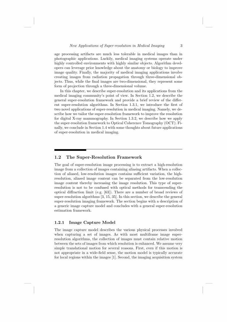
FIGURE 1.4Different restoration techniques applied on the low-dosage set of images. (a)Low-dosage image, (b) Multiframe averaged image, (c) High-dosage image at226mAs, (d) Denoised image x (15 × 11.3 = 170mAs). Restoration combin-ing the 15 low-dosage frames in (d) frames, most clearly demonstrating thepentagram-shaped set of micro-calcification cluster.
averaging the 15 low-resolution frames followed by interpolation. While theSNR is improved, the aliasing contained in the low-resolution images becomesclear as the 5 bars appear as three bars above 7 lp/mm. The third image(Fig. 1.3(c)) shows the resulting image x after applying the multiframe imagerestoration step. This image shows contrast improvement but at the expenseof significant noise amplification. The final image (Fig. 1.3(d)) shows the finalimage estimate x after applying the non-linear wavelet thresholding denoisingalgorithm. The image shows that the contrast is preserved while eliminatingmost of the amplified noise.
The primary goal of mammography is detecting and diagnosing cancerouslesions in the breast. The breast phantom includes small grains of calcium forevaluating the diagnostic capability of micro-calcifications. Figure 1.4 showsanother block from the same experiment demonstrating the ability of thenonlinear denoising algorithm to clearly eliminate noise while preserving the

New Applications of Super-resolution in Medical Imaging 15
signal for a cluster of 0.275 mm sized calcite grains. This provides confidencein the nonlinear denoising algorithm’s ability to discern signal from noise.
1.3.2 Super-Resolution in Optical Coherence Tomography
The invention and utilization of Optical Coherence Tomography (OCT), firstreported in [27] in 1991, has had a profound impact on many fields of research,especially ophthalmic sciences [25, 26, 46, 49, 55]. OCT systems provide non-invasive yet high-resolution in-vivo images of retinal structures, which can beused to define imaging biomarkers of the onset and progression of many oph-thalmic diseases. By employing an interferometer [8, 17], several OCT basedimaging systems have been developed through out the years, most notablythe time-domain OCT (TDOCT) and ultrahigh resolution OCT (UHROCT)[40]. The advent of the Spectral Domain Optical Coherence Tomography(SDOCT) system has further improved the image quality and acquisitionspeed [33, 51, 60, 61, 64, 65]. Today, several commercial SDOCT systemsare available with similar capabilities and 20-30 kHz A-scan rates.
A noninvasive, accurate characterization of retinal lesions and other patho-logical abnormalities is only possible with high-resolution, 3-D ocular imag-ing. Commonly, the lateral, axial, and azimuthal resolution of many imagingsystems, including OCT, are associated with (and calculated based on) theillumination source characteristics (e.g. bandwidth), the optical path (e.g.diffraction limit due to pupil diameter, ocular aberrations, dispersion, etc.),and other physical characteristics. Utilization of fast and efficient CCD de-tectors has facilitated the creation of aliasing-free 3-D images of anatomicalstructures. However, for some in vivo imaging applications, the SDOCT acqui-sition time is not short enough to avoid abrupt motions such as blinking, thuscreating motion artifacts in the densely sampled volumetric measurements(Fig. 1.6). Therefore, in practice, to speed up the image acquisition process,these systems are utilized at a significantly lower than nominal resolution. InSDOCT imaging, practical resolution in the azimuthal axis corresponds to thenumber of B-scans sampled at relatively equal distances in a volumetric scan-ning scheme (Fig. 1.5). Note that, valid quantitative measurements of retinaldisease biomarkers (e.g. drusen [56] volume) are only feasible from B-Scanswith known azimuthal displacement.
On the quest to gather useful information from SDOCT through improv-ing the hardware design, one quickly runs into the problem of diminishingreturns. Specifically, the optical components necessary to capture very high-quality, dense scans become prohibitively expensive or too sensitive for manypractical applications. Unlike alternative approaches that require expensivehardware such as eye tracking systems [22], we propose a software-based im-age processing solution in this section based on our earlier work [12], that isapplicable to virtually any SDOCT imaging system, including the handheldSDOCT systems which are more prone to motion errors [5, 6, 47].
In this section, we introduce a novel application of the super-resolution

16 Digital Imaging and Computer Vision
FIGURE 1.5A volumetric SDOCT scan set is a collection of azimuthally sampled B-Scans(a), creating a 3-D view of the retina (b). The braces in (a,b) mark the lowerretinal slab shown in (c) containing the shadows from the overlying largervessels. (d) is the summed voxel projection (SVP) created by axial projectionof the lower half of the B-Scans, demonstrating the vessel pattern [22, 28].Each B-Scan corresponds to one line on the SVP.
framework for improving the azimuthal resolution of SDOCT images. Wepropose a method based on capturing several repeated fast sparse 3-D scans,followed by detecting and removing the ones affected by motion artifacts, andfinally fusing the artifact-free scans. Our approach to reduce motion artifactsin the 3-D tomographic structure, in spirit, is close to the multi-camera time-space super-resolution [48], MRI inter-slice reconstruction [21], and video syn-chronization [57] problems. However, the proposed reconstruction algorithmsand applications are fundamentally different and novel.
1.3.2.1 Proposed Method: Sparse Repeated Imaging
Our goal is to transcend the limitations of SDOCT imaging systems, reducemotion artifacts (Fig. 1.6), and obtain densely sampled, high-quality, and
New Applications of Super-resolution in Medical Imaging 17
(a) (b)
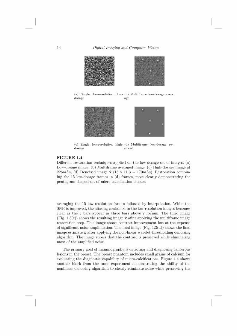
FIGURE 1.6SVPs from densely sampled volumetric SDOCT scans of two subjects. Thered ellipsoids mark motion artifact locations.
accurate 3-D SDOCT images of unpredictably moving structures such as ahuman eye. In typical SDOCT ophthalmic imaging practice, the region of in-terest is swept with a relatively high number of B-Scans. For many patients,due to the multiple seconds required to capture scans, a dense scanning strat-egy is prone to motion artifacts such as blinking.
Alternatively, we propose to capture several (N) sparsely sampled vol-umetric scans with a significantly lower number of B-Scans than the targetresolution. Since the number of frames in each sequence (K) is relatively small,each scan is captured very fast. Therefore, it is reasonable to assume that someof these sequences will be less affected by the abrupt patient motion. We de-tect such sequences, reorder and interlace their frames, and create a denselysampled, artifact-free representation of the retina. Figure 1.7 represents themain idea, where two sparsely sampled sequences are fused together creatinga dense representation of the underlying pathological structures.
Putting together the frames of different scan sets (interlacing) in a correctorder is a challenging task. A naive approach involves sorting via pair-wise reg-istration and computing a closeness measure (e.g. normalized cross-correlationor sum-of-squared difference) of all frames. In the case of fusing only two vol-umetric B-Scan sets, each frame in the first volume sequence is registered toall frames of the second sequence. Then, in the fused output sequence, thisindividual frame is inserted into the second sequence nearest to the framein the second sequence with the highest cross-correlation value. This processwould be repeated for all remaining frames in the first sequence. Of course,this is a simplified variation of the video synchronization problem, discussedin detail in the computer vision literature [57]. However, aside from the pro-hibitively heavy computational load of registering large SDOCT data sets, the

18 Digital Imaging and Computer Vision
SNR of the SDOCT images is significantly lower than the commercial cam-corders for which the method in [57] is developed. Therefore, the commonlyused closeness measures such as normalized cross-correlation may not alwaysbe sensitive enough to discriminate between very small structural changes inthe neighboring SDOCT ophthalmic scans (Fig. 1.7).
FIGURE 1.7Fusing (interlacing) multiple sparsely sampled scan sequences to create anazimuthally higher resolution volume of B-Scans. Indeed, unlike this schematicexample, in clinical applications the displacement between sequences might benon-integer as it is induced by patient motion.
To reduce the computational complexity of 3-D registration and improveaccuracy, we introduce an alternative global solution based on 2-D registra-tion. Note that, the azimuthal axis displacement is the only motion that weneed to estimate to be able to interlace the 3-D volumetric scans. A quickconsultation with Figure 1.5 shows that the y-axis in the 2-D SVP imagescorresponds to the azimuthal axis in the 3-D data volumes. Therefore, insteadof dealing with full 3-D datasets, we axially project the input 3-D sequencesand create corresponding SVP images (Fig. 1.5). This will reduce the taskof registering K sets each with B images (B-Scans) of size [B × L] pixels, toregistering only K images (SVPs) each of size [B ×B] pixels. In essence, weare projecting down into the SCP domain to create a collection of K imagesthat are undersampled in only one dimension (e.g. D1 = 1).
Aside from a significant reduction in data volume, the axial projectionreduces the noise in the SVP images by averaging over hundreds of pixels. AsSNR of the SVP images is relatively higher, outlier (motion artifact corrupted)image sets can be more accurately detected and excluded from the data pool.
We recover the order of the frames in the dense 3-D output by registeringthe remaining SVPs. As explained in the next subsection, we calculate the y-axis motion between different SVPs and associate this to the azimuthal motion

New Applications of Super-resolution in Medical Imaging 19
parameters (frame number) of the 3-D volumes. For example, an estimatedfive pixel displacement for the SVPs of two scan sets in y-axis, indicates anoffset of five frames in the corresponding B-Scan sequences. Moreover, byestimating the x -axis motion of the SVPs, we recover the lateral registrationparameters needed for aligning the fused (interlaced) B-Scans in the final fused3-D volume.
1.3.2.2 Multiframe Joint Registration
In many super-resolution applications, fast pairwise image registration is suf-ficient for estimating the relative shifts between the sets of low-resolutionimages. The basis for this approach is based on the following approximationof Equation (1.5)
yk = DS(vk)z ≈ S(v′k)p + ek + ak (1.16)
where v′k = [v1,kv2,k/D2] is the apparent motion in the undersampled image,p is the approximate non-aliased portion of the low-resolution image, and ak
is the aliasing artifacts which we approximately treated as noise. From thesimplified model of Equation (1.16), we see that the relationship between apair of low-resolution images yk and yj is approximately given by
yk = S(v′j − v′k)yj ≈ yj + (v′j − v′k)∇S(0)yj (1.17)
where the second half of the equation is based on the first order Taylor ap-proximation of the shift operator S(v). In practice, the operators ∇S(0) =[Sx(0)Sy(0)] are approximately the x and y gradient operators. Equation(1.17) is known as the optical flow constraint and can be used to estimatethe shift between any pair of low-resolution frames. Such an approach worksas long as the energy in the aliasing artifacts ak are minimal. We use thenotation v′j−k = v′j − v′k.
Due to the sub-Nyquist sampling in the azimuthal direction, the SVPs ofthe sparse, fast-acquired sequences are aliased in the y-axis, complicating thesubpixel motion estimation task. Moreover, small estimation bias in the pair-wise SVP registration is magnified to a significant misalignment error whenseveral sequences are fused together. Therefore, to minimize the overall motionestimation error, we exploit global consistency conditions in a multiframe mo-tion estimation framework [14, 19]. This bundle-adjusted, optical flow-basedtechnique relies on the fact that the operator describing the motion betweenany pair of frames must be the composition of the operators between two otherpairs of frames. In effect, by incorporating this prior information in the jointmotion estimation framework of [14], we minimize the motion estimation biaswhile having extremely fast registration by estimating motion entirely in thelow-resolution domain.
We overcome the errors associated using a global constraint enforcing thetransitivity of the pairwise motion estimates. For example, if we consider three
20 Digital Imaging and Computer Vision
frames, then the transitivity of the motion estimates requires that
v′k−j = v′l−j + v′k−l (1.18)
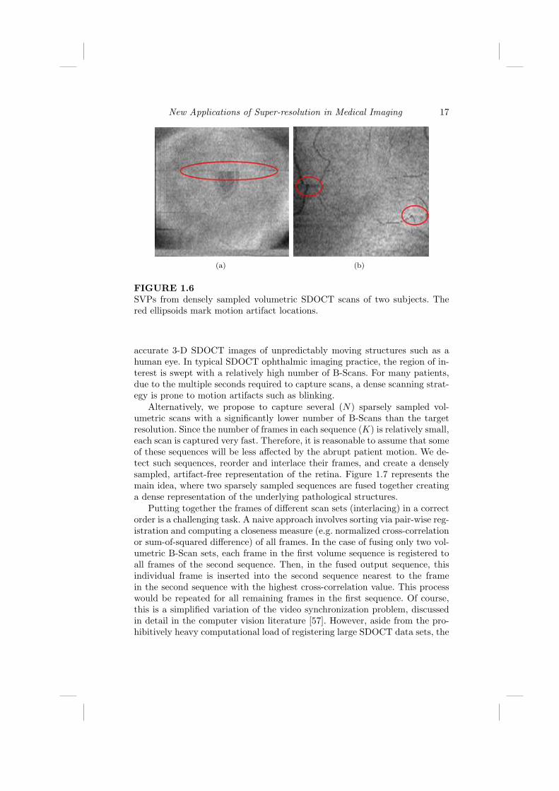
Figure 1.8 schematically describes this motion constraint. In the case of mul-tiple translational motion vectors [14], the above conditions can be describedby simple linear equations relating the motion vectors between the frames as
FIGURE 1.8Global motion consistency conditions that exist for any set of images: theoperator describing the motion between any pair of images is the compositionof the operators between two other pairs of images: vi,k = vi,j + vj,k.
UV = 0 , (1.19)
where U is a[2(K−1)2 × 2K(K−1)
]consistency condition matrix and U is
a vector collecting the set of unknown motion vectors v′k. Each row in thesparse matrix U has only two or three non-zero (±1) elements. Motion vectorsare estimated by minimizing a global cost function such as

New Applications of Super-resolution in Medical Imaging 21
ΩOF(V ) =K∑
i 6=j
∥∥yi − yj − v′i−j∇S(0)yj
∥∥1, s.t. UV = 0 , (1.20)
We used nonlinear programming (“fmincon” function in MATLAB) to min-imize this cost function. The above conditions for the more general case ofaffine motion are defined in [14]. This is a simpler but faster implementationof the general framework described in Section 1.2. Since we do not estimatethe high-resolution image jointly with the registration parameters our solutionis suboptimal. Indeed, mathematically more rigorous solutions for registeringaliased images are also possible [42], which increase computational complex-ity of the proposed algorithm. However, noting the extremely large SDOCTimage sets (hundreds of images of size [512× 1024] or larger), the goal of ourproposed solution is to be practical for clinical implementation rather thanmathematically optimal.
1.3.2.3 Experimental Results
The above registration technique recovers the order and the relative azimuthaldistance of B-Scans from different scan sets, which can be exploited to recon-struct a dense 3-D view of the imaged pathological structure. Since misalignedor broken vessels are easily detectable in retinal imaging applications, the ves-sel pattern as seen on the SVP serves as an efficient qualitative measure of thesuccess and accuracy of the overall algorithm. Therefore, we use the estimatedmotion parameters to reconstruct a fused (super-resolved) 2-D SVP map ofretinal vessel structure.
Figure 1.6 shows a dense scanning of a subject, whose motion artifactshave resulted in an SVP with broken vessel structure. From the same subject,we captured 12 sparsely sampled volumetric scans (each with 50 B-Scans)and adjusted the baseline of each image using the fast registration StackRegplug-in (Biomedical Imaging Group; Swiss Federal Institute of TechnologyLausanne) [54] for ImageJ (freeware; National Institutes of Health; Bethesda,MD). Following [28], by summing the lower half of the B-Scans in the ax-ial direction, we created SVPs with distinct vessel patterns. After contrastadjustment, four of the six sequences with the highest SVP normalized cross-correlation values were manually selected to be registered. Figures 1.9(a) and1.9(b) show two corresponding SVPs of these four sequences. Registered andsequentially ordered AVI movies of these four input sequences are availablein http://www.duke.edu/∼sf59/datasets/SDOCT SR.avi, screenshots of whichare shown in Figure 1.9(f).
We used the multiframe projective bundle-adjusted motion estimationmethod of [14] to recover the subpixel translational motion parameters of thesefour SVPs (Sec. 1.3.2.2). We used the fast zero-order classic kernel regression-based super-resolution algorithm described in [52] to reconstruct the fusedSVP. Since there are no aliasing artifacts in the x -axis (lateral direction), the

22 Digital Imaging and Computer Vision
SVP resolution is only enhanced in the y-axis. The SVP of the fused sequenceis shown in Figure 1.9(c), which has more details than any of the input SVPs.
As a point of reference, we also captured a gold-standard sequence shownin Figure 1.9(d), which is the visually best of 4 densely sampled volumetricscans (100 B-Scans). The reconstruction accuracy and quality improvementis confirmed by comparing the input and output SVPs to the gold-standard.We believe the small jaggedness in reconstructed vessels of Figure 1.9(c) ismainly due to the dynamic structural deformation of the vessels during thecardiac cycle. Overall, the vessel pattern in Figure 1.9(c) shows fewer dis-continuities (blue ellipsoids) compared to the input SVPs. Moreover, due tothe less aggressive interpolation in the azimuthal (y-axis) direction, the vesselthicknesses are more accurate in Figure 1.9(c) than in any of the input frames(red ellipsoids).
1.4 Conclusion
We have provided a proof of concept for the applicability of image process-ing based algorithms as an alternative to expensive hardware for creatingrobust high quality X-ray mammography and SDOCT ophthalmic imaging.The proposed super-resolution-based algorithm enables ophthalmic imagingpractitioners and radiologists to optimally utilize the SDOCT and X-ray sys-tems in their highest resolution capacity.
For the SDOCT case, several implementation variations for improving theefficiency are possible. For example, rather than discarding a whole defectedsequence, we may discard only those B-Scans affected by abrupt motion arti-facts (e.g. blinking), and use the remaining uncorrupted B-Scans. To producemore visually appealing SVPs, more efficient super-resolution techniques suchas the steering adaptive kernel [52] or robust super-resolution [16] may be alsoexploited. Moreover, incorporation of an advanced adaptive sparse samplingstrategy (3-D extension of the method in [13]) in this imaging framework ispart of our ongoing research.
While the proposed algorithm efficiently removes abrupt motion artifacts,a practical drawback is the case of imaging objects with constant deformablemotion. For example, in the case of imaging pulsing blood vessels, each sparsesequence is associated with a unique position of the blood vessels compared tothe background tissues. A possible remedy is synchronizing the start of imageacquisition in each sparse sequence with the electrocardiogram (EKG) signal.
We note that two alternative related sparse imaging scenarios can be alsoconsidered. One is based on capturing large field of view repeated scans, densein the azimuthal direction but sparsely sampled in the lateral direction. Then,a classic super-resolution algorithm (e.g. [16, 52]) may reconstruct the lateralresolution of individual B-Scans. Our pilot experimental results have shown

New Applications of Super-resolution in Medical Imaging 23
moderate improvements, when imaging objects under a SDOCT microscope.However, in practical clinical trials the difficulty of capturing repeated scansfrom a unique azimuthal location largely voids the applicability of this strat-egy.
Alternatively, the authors of the published work in [66] propose to captureazimuthally dense scan sets with a small field of view in the axial-lateral plane(e.g. the en face view is divided into four sub-sections, which are imagedsubsequently). A customized semi-automatic software stitches the 3-D scanvolumes, creating a visually appealing, large field of view, 3-D rendition ofthe retina. However, unfortunately for the same practical imaging problemnoted for the aforementioned strategy, as evident in the experimental resultsin [66], it is extremely hard (if not impossible) to recover unique, large fieldof view B-Scans without evident registration artifacts.
As for the mammography, we believe the design of future X-ray imag-ing systems would benefit from a systematic analysis of the resolution andSNR required for mammographic screening and diagnosis. In the future, wewill explore the fundamental tradeoffs between radiation exposure, numberof frames, and reconstruction performance. Furthermore, we will investigatemore sophisticated redundant wavelet techniques such as curvelets [50] orridgelets [7] which might show even better performance than the proposedmultiframe ForWaRD technique. In fact, recent research has shown that useof more sophisticated wavelets can improve the image quality in other medicalimaging applications [31].
We believe this novel application of super-resolution can be used as astepping stone toward many other image fusion based medical imaging systemdesigns, aimed especially at patients with uncontrollable motion, pediatrics,or hand-held probe imaging. While this chapter was focused on X-ray andOCT image enhancement, similar strategies can be exploited for enhancing thequality of some other volumetric medical imaging devices such as ultrasound.
1.5 Acknowledgment
Our MATLAB software implementation of the noted X-ray algorithms is inpart based on the ForWarD software, developed by Dr. Ramesh D. Neela-mani of the Digital Signal Processing group at Rice University (available athttp://www.dsp.rice.edu/software/ward.shtml). We would like to thank theEditor Prof. Peyman Milanfar for collaborating with us in the original multi-frame X-ray motion estimation publications. We thank Bradley A. Bower andYuankai K. Tao for providing invaluable SDOCT data and assistance. Thiswork was supported in part by North Carolina Biotechnology Center Collab-orative Funding Grant ]2007-CFG-8005 with Bioptigen, the Duke Transla-tional Medicine Institute Subcontract ]12 of NIH Grant ]5ULT-RR024128-

24 Digital Imaging and Computer Vision
03, Knights Templar Eye Foundation Inc. Pediatric Ophthalmology ResearchGrant, Hartwell Foundation Individual Biomedical Research Award.

New Applications of Super-resolution in Medical Imaging 25
(a) (b)
(c) (d)
(e) (f)
FIGURE 1.9(a) and (b) are two representative SVPs of four input retinal SDOCT se-quences (50 regularly sampled B-Scans each). (c) is the SVP of the fusedsequence (200 irregularly sampled B-Scans). (d) is the Gold-Standard SVPwhich is the best dense (100 regularly sampled B-Scans) out of 4 such se-quences (Figure 1.6(b) is an example of dense sampling of the same subjectwith motion artifacts). (e) and (f) are the screen shots of the AVI moviesof registered four input B-Scan sets and the reordered and interlaced outputB-Scan set, respectively (2.1 MB).

26 Digital Imaging and Computer Vision

Bibliography
[1] Y. Altunbasak, A. Patti, and R. Mersereau. Super-resolution still andvideo reconstruction from MPEG-coded video. IEEE Trans. CircuitsAnd Syst. Video Technol., 12(4):217–226, Apr. 2002.
[2] L.D. Alvarez, J. Mateos, R. Molina, and A.K. Katsaggelos. High reso-lution images from compressed low resolution video: Motion estimationand observable pixels. International Journal of Imaging Systems andTechnology, 14(2):58–66, October 2004.
[3] S. Borman and R.L. Stevenson. Super-resolution from image sequences- a review. In Proc. of the 1998 Midwest Symposium on Circuits andSystems, volume 5, Apr. 1998.
[4] S.G. Chang, B. Yu, and M. Vetterli. Adaptive wavelet thresholding forimage denoising and compression. IEEE Transactions on Image Process-ing, 9(9):1532–1546, 2000.
[5] S.H. Chavala, S. Farsiu, R. Maldonado, D.K. Wallace, S.F. Freedman,and C.A. Toth. Insights into Advanced Retinopathy of Prematurity UsingHandheld Spectral Domain Optical Coherence Tomography Imaging. inpress, Ophthalmology, 2009.
[6] G.T. Chong, S. Farsiu, S.F. Freedman, N. Sarin, A.F. Koreishi, J.A. Izatt,and C.A. Toth. Abnormal foveal morphology in ocular albinism imagedwith spectral-domain optical coherence tomography. Archives of Oph-thalmology, 127(1):37–44, 2009.
[7] M. Do and M. Vetterli. The finite ridgelet transform for image represen-tation. IEEE Trans. Image Process., 12(1):16–28, January 2003.
[8] C. Dunsby and P.M.W. French. Techniques for depth-resolved imag-ing through turbid media including coherence-gated imaging. Journal ofPhysics D: Applied Physics, 36:207–227, July 2003.
[9] N.A. El-Yamany and P.E. Papamichalis. Robust color image superresolu-tion: An adaptive m-estimation framework. EURASIP Journal on Imageand Video Processing, 8:1–12, 2008.
[10] M. Elad and A. Feuer. Restoration of a single superresolution imagefrom several blurred, noisy, and undersampled measured images. IEEETransactions on Image Processing, 6(12):1646–1658, Dec 1997.
27

28 Digital Imaging and Computer Vision
[11] M. Elad and Y. Hel-Or. A fast super-resolution reconstruction algorithmfor pure translational motion and common space invariant blur. IEEETransactions on Image Processing, 10(8):1186–1193, August 2001.
[12] S. Farsiu, B.A. Bower, J.A. Izatt, and C.A. Toth. Image Fusion BasedResolution Enhancement of Retinal Spectral Domain Optical CoherenceTomography Images. Invest. Ophthalmol. Vis. Sci., 49(5):E–abstract–1845, 2008.
[13] S. Farsiu, J. Christofferson, B. Eriksson, P. Milanfar, B. Friedlander,A. Shakouri, and R. Nowak. Statistical detection and imaging of ob-jects hidden in turbid media using ballistic photons. Applied Optics,46(23):5805–5822, 2007.
[14] S. Farsiu, M. Elad, and P. Milanfar. Constrained, globally optimal, multi-frame motion estimation. In Proc. of the 2005 IEEE Workshop on Sta-tistical Signal Processing, pages 1396–1401, July 2005.
[15] S. Farsiu, D. Robinson, M. Elad, and P. Milanfar. Advances and chal-lenges in super-resolution. International Journal of Imaging Systems andTechnology, 14:47–57, 2004.
[16] S. Farsiu, M.D. Robinson, M. Elad, and P. Milanfar. Fast and robustmultiframe super resolution. IEEE Transactions on Image Processing,13(10):1327–1344, October 2004.
[17] A.F. Fercher, W. Drexler, C.K. Hitzenberger, and T. Lasser. Opticalcoherence tomography - principles and applications. Reports on Progressin Physics, 66(2):239–303, 2003.
[18] G. Golub and V. Pereyra. Separable nonlinear least squares: the vari-able projection method and its applications. Institute of Physics, InverseProblems, 19:R1–R26, 2002.
[19] V.M. Govindu. Lie-algebraic averaging for globally consistent motionestimation. In Proc. of the Int. Conf. on Computer Vision and PatternRecognition (CVPR), volume 1, pages 684–691, July 2004.
[20] H. Greenspan. Super-resolution in medical imaging. The Computer Jour-nal, 52:43–63, 2009.
[21] H. Greenspan, G. Oz, N. Kiryati, and S. Peled. MRI inter-slice reconstruc-tion using super-resolution. Magnetic Resonance Imaging, 20(5):437–446,2002.
[22] D. Hammer, R.D. Ferguson, N. Iftimia, T. Ustun, G. Wollstein,H. Ishikawa, M. Gabriele, W. Dilworth, L. Kagemann, and J. Schuman.Advanced scanning methods with tracking optical coherence tomography.Optics Express, 13(20):7937–7947, 2005.

New Applications of Super-resolution in Medical Imaging 29
[23] R. Hardie. A fast image super-resolution algorithm using an adaptivewiener filter. IEEE Transactions on Image Processing, 16(12):2953–2964,December 2007.
[24] R. Hardie, K. Barnard, and E. Armstrong. Joint MAP registration andhigh-resolution image estimation using a sequence of undersampled im-ages. IEEE Transactions on Image Processing, 6(12):1621–1633, 1997.
[25] M.R. Hee, J.A. Izatt, E.A. Swanson, D. Huang, J.S. Schuman, C.P. Lin,C.A. Puliafito, and J.G. Fujimoto. Optical coherence tomography of thehuman retina. Archives of Ophthalmology, 113(3):325–332, 1995.
[26] D.B. Hess, S.G. Asrani, M.G. Bhide, L.B. Enyedi, S.S. Stinnett, andS.F. Freedman. Macular and retinal nerve fiber layer analysis of normaland glaucomatous eyes in children using optical coherence tomography.American Journal of Ophthalmology, 139(3):509–517, 2005.
[27] D. Huang, E.A. Swanson, C.P. Lin, J.S. Schuman, W.G. Stinson,W. Chang, M.R. Hee, T. Flotte, K. Gregory, C.A. Puliafito, et al. Opticalcoherence tomography. Science, 254(5035):1178–1181, 1991.
[28] S. Jiao, R. Knighton, X. Huang, G. Gregori, and C. Puliafito. Simultane-ous acquisition of sectional and fundus ophthalmic images with spectral-domain optical coherence tomography. Optics Express, 13(2):444–452,2005.
[29] J.A. Kennedy, O. Israel, A. Frenkel, R. Bar-Shalom, and H. Azhari.Super-resolution in PET imaging. IEEE transactions on medical imaging,25(2):137–147, 2006.
[30] J.A. Kennedy, O. Israel, A. Frenkel, R. Bar-Shalom, and H. Azhari. Im-proved image fusion in PET/CT using hybrid image reconstruction andsuper-resolution. Int. J. Biomed. Imaging, 46846, 2007.
[31] A. Khare and U.S. Tiwary. A new method for deblurring and denoising ofmedical images using complex wavelet transform. Proc. IEEE ConferenceEngineering in Medicine and Biology, pages 1897–1900, Sept. 2005.
[32] S. Lertrattanapanich and N.K. Bose. High resolution image formationfrom low resolution frames using Delaunay triangulation. IEEE Trans.Image Processing, 11(12):1427–1441, Dec. 2002.
[33] N. Nassif, B. Cense, B.H. Park, S.H. Yun, T.C. Chen, B.E. Bouma, G.J.Tearney, and J.F. de Boer. In vivo human retinal imaging by ultrahigh-speed spectral domain optical coherence tomography. Optics Letters,29(5):480–482, 2004.
[34] R. Neelamani, H. Choi, and R. Baraniuk. Forward: Fourier-wavelet regu-larized deconvolution for ill-conditioned systems. IEEE Transactions onImage Processing, 52(2):418–433, February 2004.

30 Digital Imaging and Computer Vision
[35] S.C. Park, M.K. Park, and M.G. Kang. Super-resolution image recon-struction: a technical overview. Signal Processing Magazine, 20(3):21–36,2003.
[36] V. Patanavijit and S. Jitapunkul. A lorentzian stochastic estimationfor a robust iterative multiframe super-resolution reconstruction withLorentzian-Tikhonov regularization. EURASIP Journal on Image andVideo Processing, 2007(2), 2007.
[37] R.R. Peeters, P. Kornprobst, M. Nikolova, S. Sunaert, T. Vieville, G. Ma-landain, R. Deriche, O. Faugeras, M. Ng, and P. Van Hecke. The use ofsuper-resolution techniques to reduce slice thickness in functional MRI.International Journal of Imaging Systems and Technology, 14(3):131–138,2004.
[38] S. Peled and Y. Yeshurun. Superresolution in MRI: Application to hu-man white matter fiber tract visualization by diffusion tensor imaging.Magnetic resonance in medicine, 45(1):29–35, 2001.
[39] L.C. Pickup, D.P. Capel, S.J. Roberts, and A. Zisserman. Bayesian meth-ods for image super-resolution. The Computer Journal, 2007.
[40] C.G. Pieroni, A.J. Witkin, T.H. Ko, J.G. Fujimoto, A. Chan, J.S. Schu-man, H. Ishikawa, E. Reichel, and J.S. Duker. Ultrahigh resolution opticalcoherence tomography in non-exudative age related macular degenera-tion. British Medical Journal, 90(2):191–197, 2006.
[41] D. Robinson, S. Farsiu, J.Y. Lo, P. Milanfar, and C.A. Toth. Efficientmultiframe registration of aliased x-ray images. Proceedings of the 41thAsilomar Conference on Signals, Systems, and Computers, pages 215–219, November 2007.
[42] D. Robinson, S. Farsiu, and P. Milanfar. Optimal registration of aliasedimages using variable projection with applications to super-resolution.The Computer Journal, 52(1):31–42, January 2009.
[43] D. Robinson and P. Milanfar. Statistical performance analysis of super-resolution. IEEE Transactions on Image Processing, 15(6):1413–1428,June 2006.
[44] M.D. Robinson, C.A. Toth, J.Y. Lo, and S. Farsiu. Efficient fourier-wavelet super-resolution with applications in low-dosage digital x-rayimaging. submitted to IEEE Transactions on Image Processing, January2009.
[45] R.R. Schultz and R.L. Stevenson. Extraction of high-resolution framesfrom video sequences. IEEE Transactions on Image Processing, 5(6):996–1011, June 1996.

New Applications of Super-resolution in Medical Imaging 31
[46] S.G. Schuman, A.F. Koreishi, S. Farsiu, S. Jung, J.A. Izatt, and C.A.Toth. Photoreceptor layer thinning over drusen in eyes with age-relatedmacular degeneration imaged in vivo with spectral-domain optical coher-ence tomography. Ophthalmology, 116(3):488–496, 2009.
[47] A.W. Scott, S. Farsiu, L.B. Enyedi, D.K. Wallace, and C.A. Toth. Imag-ing the infant retina with a hand-held spectral-domain optical coherencetomography device. American Journal of Ophthalmology, 147(2):364–373,2009.
[48] E. Shechtman, Y. Caspi, and M. Irani. Space-time super-resolution. IEEETransactions on Pattern Analysis and Machine Intelligence, 27(4):531–545, 2005.
[49] V.J. Srinivasan, M. Wojtkowski, A.J. Witkin, J.S. Duker, T.H. Ko,M. Carvalho, J.S. Schuman, A. Kowalczyk, and J.G. Fujimoto. High-definition and 3-dimensional imaging of macular pathologies with high-speed ultrahigh-resolution optical coherence tomography. Ophthalmology,113(11):2054–2054, 2006.
[50] J. Starck, E. Candes, and D. Donoho. The curvelet transform for imagedenoising. IEEE Trans. Image Process., 11(6):670–684, June 2002.
[51] M. Stopa, B.A. Bower, E. Davies, J.A. Izatt, and C.A. Toth. Correlationof pathologic features in spectral domain optical coherence tomographywith conventional retinal studies. Retina, 28(2):298–308, 2008.
[52] H. Takeda, S. Farsiu, and P. Milanfar. Kernel regression for image pro-cessing and reconstruction. IEEE Trans. Image Process., 16(2):349–366,Feb. 2007.
[53] H. Takeda, S. Farsiu, and P. Milanfar. Deblurring using regularized lo-cally adaptive kernel regression. IEEE Transactions on Image Processing,17(4):550–563, April 2008.
[54] P. Thevenaz, U.E. Ruttimann, and M. Unser. A pyramid approach tosubpixel registration based on intensity. IEEE Transactions on ImageProcessing, 7(1):27–41, 1998.
[55] C.A. Toth, R. Birngruber, S.A. Boppart, M.R. Hee, J.G. Fujimoto, C.D.DiCarlo, E.A. Swanson, C.P. Cain, D.G. Narayan, G.D. Noojin, et al.Argon laser retinal lesions evaluated in vivo by optical coherence tomog-raphy. American Journal of Ophthalmology, 123(2):188–98, 1997.
[56] C.A. Toth, S. Farsiu, A.A. Khanifar, and G.T. Chong. Optical coherencetomography in age-related macular degeneration. In Gabriel Coscas, edi-tor, Application of Spectral Domain OCT in AMD, pages 15–34. SpringerMedizin Verlag Heidelberg, 2009.

32 Digital Imaging and Computer Vision
[57] M. Ushizaki, T. Okatani, and K. Deguchi. Video synchronization based onco-occurrence of appearance changes in video sequences. Pattern Recog-nition, International Conference on, 3:71–74, 2006.
[58] P. Vandewalle, L. Sbaiz, J. Vandewalle, and M. Vetterli. Super-resolutionfrom unregistered and totally aliased signals using subspace methods.IEEE Transactions on Signal Processing, 55(7):3687–3703, July 2007.
[59] P. Vandewalle, S. Susstrunk, and M. Vetterli. A frequency domainapproach to registration of aliased images with application to super-resolution. EURASIP Journal on Applied Signal Processing, page ArticleID 71459, 2006.
[60] M. Wojtkowski, R. Leitgeb, A. Kowalczyk, T. Bajraszewski, and A.F.Fercher. In vivo human retinal imaging by fourier domain optical coher-ence tomography. Journal of Biomedical Optics, 7(3):457–463, 2002.
[61] M. Wojtkowski, V. Srinivasan, T. Ko, J. Fujimoto, A. Kowalczyk, andJ. Duker. Ultrahigh-resolution, high-speed, fourier domain optical co-herence tomography and methods for dispersion compensation. OpticsExpress, 12(11):2404–2422, 2004.
[62] N. Woods, N. Galatsanos, and A. Katsaggelos. Stochastic methods forjoint registration, restoration, and interpolation of multiple undersampledimages. IEEE Transactions on Image Processing, 15(1):201–213, January2006.
[63] Y. Yasuno, J. Sugisaka, Y. Sando, Y. Nakamura, S. Makita, M. Itoh,and T. Yatagai. Non-iterative numerical method for laterally superre-solving Fourier domain optical coherence tomography. Optics Express,14(3):1006–1020, 2006.
[64] S. Yun, G. Tearney, J. de Boer, N. Iftimia, and B. Bouma. High-speed op-tical frequency-domain imaging. Optics Express, 11(22):2953–2963, 2003.
[65] R. Zawadzki, S. Jones, S. Olivier, M. Zhao, B. Bower, J. Izatt, S. Choi,S. Laut, and J. Werner. Adaptive-optics optical coherence tomographyfor high-resolution and high-speed 3d retinal in vivo imaging. OpticsExpress, 13(21):8532–8546, 2005.
[66] R.J. Zawadzki, A.R. Fuller, S.S. Choi, D.F. Wiley, B.Hamann, and J.S.Werner. Improved representation of retinal data acquired with volumetricfd-oct: co-registration, visualization, and reconstruction of a large field ofview. volume 6844, page 68440C. SPIE, 2008.