new applications and development of active, semi-active and
TRANSCRIPT

Proceedings of International Post-SMiRT Conference Seminar on Seismic Isolation, Passive Energy Dissipation and Active Control of Vibration of Structures
Cheju, Korea, August 23-25, 1999
NEW APPLICATIONS AND DEVELOPMENT OF
ACTIVE, SEMI-ACTIVE AND HYBRID CONTROL TECHNIQUES FORSEISMIC AND NON-SEISMIC VIBRATION IN THE USA
B.F. Spencer, Jr.Department of Civil Engineering and Geological Sciences,University of Notre Dame, Notre Dame, IN 46556, USA
T.T. SoongDepartment of Civil, Structural and Environmental Engineering,
State University of New York at Buffalo, Buffalo, NY 14260, USA
ABSTRACT
In recent years, considerable attention has been paid to research and development of structural control devices, with particular emphasis on alleviation of wind and seismic response ofbuildings and bridges. In both areas, serious efforts have been undertaken to develop thestructural control concept into a workable technology, and today we have many such devicesinstalled in a wide variety of structures.
The focus of this state-of-the-art paper is on active, semi-active and hybrid structuralcontrol developments in the USA. Control systems are force actuation devices integrated with sensors, controllers and real-time information processing. This paper includes a briefhistorical outline of their development and an assessment of the state-of-the-art and state-of-the-practice of this exciting, and still evolving, technology. Seismic and non-seismicapplications will be presented. Also included in the discussion are their advantages andlimitations in the context of seismic design and retrofit of civil engineering structures.
1. INTRODUCTION
Active, semi-active and hybrid structural control systems are a natural evolution of passivecontrol technologies such as base isolation and passive energy dissipation. The possible use of active control systems and some combinations of passive and active systems, so called hybrid systems, as a means of structural protection against wind and seismic loads has receivedconsiderable attention in recent years. Active/hybrid control systems are force deliverydevices integrated with real-time processing evaluators/controllers and sensors within thestructure. They act simultaneously with the hazardous excitation to provide enhancedstructural behavior for improved service and safety. Remarkable progress has been made over the last twenty years. The First and Second World Conferences on Structural Control held in1994 (Housner et al., 1994b) and 1998 (Kobori et al., 1998), respectively, attracted over 700participants from 17 countries and demonstrated the worldwide interest in structural control.

As will be discussed in the following sections, research to date has reached the stage whereactive systems have been installed in full-scale structures. Active systems have also been used temporarily in construction of bridges or large span structures (e.g., lifelines, roofs) where noother means can provide adequate protection.
This rapid growth of research interest and development of active/hybrid structural controlsystems is in part due to several coordinated research efforts, largely in Japan and US, marked by a series of milestones listed in Table 1. Indeed, the most challenging aspect of activecontrol research in civil engineering is the fact that is an integration of a number of diversedisciplines, some of which are not within the domain of traditional civil engineering. Theseinclude computer science, data processing, control theory, material science, sensingtechnology, as well as stochastic processes, structural dynamics, and wind and earthquakeengineering. These coordinated efforts have facilitated collaborative research efforts amongresearchers from diverse background and accelerated the research-to-implementation processas one sees today.
Table 1: Active Structural Control Research – Milestones
Year Event1989 US Panel on Structural Control Research (US-NSF)1990 Japan Panel on Structural Response Control (Japan-SCJ)1991 Five-year Research Initiative on Structural Control (US-NSF)1993 European Association for Control of Structures1994 International Association for Structural Control1994 First World Conference on Structural Control (Pasadena, CA, USA)1998 China Panel for Structural Control1998 Second World Conference on Structural Control (Kyoto, Japan)
The purpose of this paper is to provide an assessment of the state-of-the-art and state-of-the-practice of this exciting, and still evolving, technology. Also included in the discussion aresome basic concepts, the types of active control systems being used and deployed, and theiradvantages and limitations in the context of seismic design and retrofit of civil engineeringstructures.
Structure ResponseExcitation
Figure 1a: Conventional Structure
PED
Excitation ResponseStructure
Figure 1b: Structure with Passive Energy Dissipation (PED)
Figure 1: Structure with Various Control Schemes

Figure 1 (cont.): Structure with Various Control Schemes
Figure 1d: Structure with Hybrid Control
ControlActuators
Excitation ResponseStructure
SensorsComputerController Sensors
PED
Figure 1e: Structure with Semi-Active Control
SensorsSensorsComputerController
PED
ControlActuators
Figure 1c: Structure with Active Control
Excitation ResponseStructure
ControlActuators
Sensors SensorsComputerController
Excitation Structure Response

2. ACTIVE, HYBRID AND SEMI-ACTIVE CONTROL SYSTEMS
An active structural control system has the basic configuration as shown schematically inFig. 1c. It consists of (a) sensors located about the structure to measure either externalexcitations, or structural response variables, or both; (b) devices to process the measuredinformation and to compute necessary control force needed based on a given controlalgorithm; and (c) actuators, usually powered by external sources, to produce the requiredforces.
When only the structural response variables are measured, the control configuration isreferred to as feedback control since the structural response is continually monitored and thisinformation is used to make continual corrections to the applied control forces. A feedforward control results when the control forces are regulated only by the measured excitation, whichcan be achieved, for earthquake inputs, by measuring accelerations at the structural base. Inthe case where the information on both the response quantities and excitation are utilized forcontrol design, the term feedback-feedforward control is used (Suhardjo et al., 1990).To see the effect of applying such control forces to a linear structure under ideal conditions,consider a building structure modeled by an n-degree-of-freedom lumped mass-spring-dashpot system. The matrix equation of motion of the structural system can be written as
)()()()()( ttttt EfDuKxxCxM +=++ &&& (1)
where M, C and K are the n × n mass, damping and stiffness matrices, respectively, x(t) is the n-dimensional displacement vector, the m-vector f(t) represents the applied load or externalexcitation, and r-vector u(t) is the applied control force vector. The n × r matrix D and the n ×m matrix E define the locations of the action of the control force vector and the excitation,respectively, on the structure.
Suppose that the feedback-feedforward configuration is used in which the control forceu(t) is designed to be a linear function of measured displacement vector x(t), velocity vector
)(tx& and excitation f(t). The control force vector takes the form
)()()()( tttt fGxGxGu fxx ++= && (2)
in which Gx, xG & and Gf are respective control gains which can be time-dependent.The substitution of Eq. (2) into Eq. (1) yields
(t))(ttt fDGExDGKxDGCxM fxx +=−+−+ )()()()()( &&& & (3)
Comparing Eq. (3) with Eq. (1) in the absence of control, it is seen that the effect of feedback control is to modify the structural parameters (stiffness and damping) so that it can respondmore favorably to the external excitation. The effect of the feedforward component is amodification of the excitation. The choice of the control gain matrices Gx, xG & and Gf depends on the control algorithm selected.
In comparison with passive control systems, a number of advantages associated with active control systems can be cited; among them are (a) enhanced effectiveness in response control;

the degree of effectiveness is, by and large, only limited by the capacity of the controlsystems; (b) relative insensitivity to site conditions and ground motion; (c) applicability tomulti-hazard mitigation situations; an active system can be used, for example, for motioncontrol against both strong wind and earthquakes; and (d) selectivity of control objectives;one may emphasize, for example, human comfort over other aspects of structural motionduring noncritical times, whereas increased structural safety may be the objective duringsevere dynamic loading.
While this description is conceptually in the domain of familiar optimal control theoryused in electrical engineering, mechanical engineering, and aerospace engineering, structuralcontrol for civil engineering applications has a number of distinctive features, largely due toimplementation issues, that set it apart from the general field of feedback control. Inparticular, when addressing civil engineering structures, there is considerable uncertainty,including nonlinearity, associated with both physical properties and disturbances such asearthquakes and wind, the scale of the forces involved can be quite large, there are only alimited number of sensors and actuators, the dynamics of the actuators can be quite complex,the actuators are typically very large, and the systems must be fail-safe (Soong 1990; Housner et al., 1994a, 1997; Kobori 1994; Dyke et al., 1995).
It is useful to distinguish among several types of active control systems currently beingused in practice. The term hybrid control generally refers to a combined passive and activecontrol system as depicted in Fig. 1d. Since a portion of the control objective is accomplished by the passive system, less active control effort, implying less power resource, is required.
Similar control resource savings can be achieved using the semi-active control schemesketched in Fig. 1e, where the control actuators do not add mechanical energy directly to thestructure, hence bounded-input bounded-output stability is guaranteed. Semi-active controldevices are often viewed as controllable passive devices.
A side benefit of hybrid and semi-active control systems is that, in the case of a powerfailure, the passive components of the control still offer some degree of protection, unlike afully active control system.
3. FULL-SCALE APPLICATION
As alluded to earlier, the development of active, hybrid, and semi-active control systems hasreached the stage of full-scale applications to actual structures. Table 2 lists these installations in building structures and towers, most of which are in Japan. In addition, Table 3 lists thebridges that have employed active systems during erection (Fujino, 1994; Spencer and Sain,1997). Most of these full-scale systems have been subjected to actual wind forces and ground motions and their observed performances provide invaluable information in terms of (a)validating analytical and simulation procedures used to predict actual system performance, (b) verifying complex electronic-digital-servohydraulic systems under actual loading conditions,and (c) verifying capability of these systems to operate or shutdown under prescribedconditions.

Table 2: Full Scale Implementation of Active Structural Control
Location BuildingYear
Completed Buiding UseNo. of Stories
Type of VibrationControlDevice*
Japan Kyobashi Seiwa Bldg, Tokyo 1989 Office 11 AMDKajima Research Lab. # 21, Tokyo 1990 Office 3 SAVSShimizu Tech. Lab., Tokyo 1991 Laboratory 7 AMDSendagaya INTES Bldg., Tokyo 1992 Office 11 HMDElevator Tech. Lab. 1992 Laboratory (60 m) AGSHankyu Chayamachi Bldg., Osaka 1992 Office/Hotel 34 HMDKansai Int’l Airport, Osaka 1992 Control Tower (88 m) HMDLand Mark Tower, Yokohama 1993 Office/Hotel 70 HMDOsaka Resort City 200, Osaka 1993 Office/Hotel 50 HMDLong Term Credit Bank, Tokyo 1993 Office 21 HMDAndo Nishikicho Bldg., Tokyo 1993 Office 14 HMDNTT Kuredo Motomach Bldg., Hiroshima
1993 Office/Hotel 35 HMD
Penta-Ocean Exp. Bldg., Tokyo 1994 Experimental 6 HMDShinjuku Park Tower, Tokyo 1994 Office/Hotel 52 HMDDowa Fire & Marine Ins., Osaka 1994 Office 29 HMDPorte Kanazawa, Kanazawa 1994 Office/Hotel 30 AMDMitsubishi Heavy Ind., Yokohama 1994 Office 34 HMDHamamatsu ACT Tower,Hamamatsu
1994 Office/Hotel (212 m) HMD
Riverside Sumida, Tokyo 1994 Office 33 AMDHotel Ocean 45, Miyazaki 1994 Hotel 43 HMDRIHGA Royal Hotel, Hiroshima 1994 Hotel 35 HMDHikarigaoko J City Bldg., Tokyo 1994 Office/Hotel 46 HMDOsaka WTC Bldg., Osaka 1995 Office 52 HMDDowa Kasai Phoenix Tower,Osaka
1995 Office 28 HMD
Rinku Gate Tower Bldg., Osaka 1995 Office/Hotel 56 HMDHirobe Miyake Bldg., Tokyo 1995 Office/Residential 9 HMDPlaza Ichihara, Chiba 1995 Office 12 HMDHerbis Osaka, Osaka 1997 Hotel 38 AMDNisseki Yokohama Bldg.,Yokohama
1997 Office 30 HMD
Itoyama Tower, Tokyo 1997 Office/Residential 18 HMDOtis Shibyama Test Tower, Chiba 1998 Laboratory 39 HMDBunka Gakuen, Tokyo 1998 School 20 HMDDaiichi Hotel Oasis Tower, Ohita 1998 Office/Hotel 21 HMDOdakyu Southern Tower, Tokyo 1998 Office/Hotel 36 HMDKajima Shizuoka Bldg., Shizuoka 1998 Office 5 SAHDSotetsu Takashimaya Kyoto Bldg.,Yokohama
1998 Hotel 27 HMD
Century Park Tower, Tokyo 1999 Residential 54 HMDUSA Highway I-35 Bridge, OK 1997 Highway Traffic -- SAHDTaiwan TC Tower, Kaoshiung 1999 Office 85 HMD
Shin-Jei Bldg., Taipei 1999 Office/Commerce 22 HMDChina Nanjing Communication Tower,
Nanjing1999 Communication (310 m) AMD
* AMD: Active mass Dampers; SAVS: Semi-active variable stiffness; HMD: Hybrid mass damper;SAHD: Semi-active hydraulic damper

Table 3. Bridges that Employed Active Systems During Construction
Name of Bridge YearsEmployed
Height,Weight
Frequency Range (Hz)
Moving Mass,Mass Ratio (%1)
ControlAlgorithm
No. of Controlled
ModesRainbow Bridge
Pylon 11991 ~ 1992 119m
4800 tonf0.26-0.95 6 ton x 2
0.6Feedback control 3
Pylon 2 1991 ~ 1992 117m4800 tonf
0.26-0.55 2 ton0.14
DVFB2 1
Tsurumi-Tsubasac 1992 ~ 1993 183m3560 tonf
0.27-0.99 10 ton x 20.16
Optimal regulator DVFB
1
HakuchoPylon 1
1992 ~ 1994 127.9m2400 tonf
0.13-0.68 9 tonf0.4
Sub-optimalfeedback control
1
Pylon 2 1992 ~ 1994 131m2500 tonf
0.13-0.68 4 ton x 20.36
DVFB 1
Akashi KaikyoPylons 1 & 2
1993 ~ 1995 293m24,650 tonf
-0.127- 28 ton x 20.8
Optimal regulator DVFB
1
Meiko-Central3
Pylon 11994 ~ 1995 190m
6200 tonf0.18-0.42 8 ton x 2
0.98-1.15H∞ Feedback
control
1
Pylon 2 1994 ~ 1995 1906200 tonf
0.16-0.25 0.17-0.38 1
1st KurushimaPylon 1
1995 ~ 1997 112m1600 tonf
0.23-1.67 6 ton x 20.15-2.05
Sub-optimalregulator control
3
Pylon 2 1995 ~ 1997 145m2400 tonf
0.17-1.70 10 ton x 20.3-2.6
H∞ Feedback control
3
2nd KurushimaPylon 1
1994 ~ 1997 166m4407 tonf
0.17-1.06 10 ton x 20.41
DVFB/H 2
Pylon 2 1995 ~ 1997 143m4000 tonf
0.20-1.45 10 ton x 20.54-1.01
Fuzzy control more than 3
3rd KurushimaPylon 1
1995 ~ 1996 179m4500 tonf
0.13-0.76 11 ton x 20.3-2.4
Variable gain DVFB
1
Pylon 2 1994 ~ 1996 179m4600 tonf
0.13-0.76 11 ton x 20.3-2.4
H∞ output feedback control
1
Nakajima Bridge 1995 ~ 1996 71m580 tonf
0.21-1.87 3.5 ton x 21.0-10.6
Fuzzy control 3
1 Percent of first modal mass.2 Direct Velocity Feedback.3 Cable-stayed bridge. Others are suspension bridges.
Described below are several of these systems together, in some cases, with their observedperformances. Also addressed are several practical issues in connection with actual structuralapplications of these systems.
3.1 Hybrid Mass Damper Systems
As seen from Table 2, the hybrid mass damper (HMD) is the most common control deviceemployed in full-scale civil engineering applications. An HMD is a combination of a passivetuned mass damper (TMD) and an active control actuator. The ability of this device to reduce structural responses relies mainly on the natural motion of the TMD. The forces from thecontrol actuator are employed to increase the efficiency of the HMD and to increase itsrobustness to changes in the dynamic characteristics of the structure. The energy and forcesrequired to operate a typical HMD are far less than those associated with a fully active massdamper system of comparable performance.
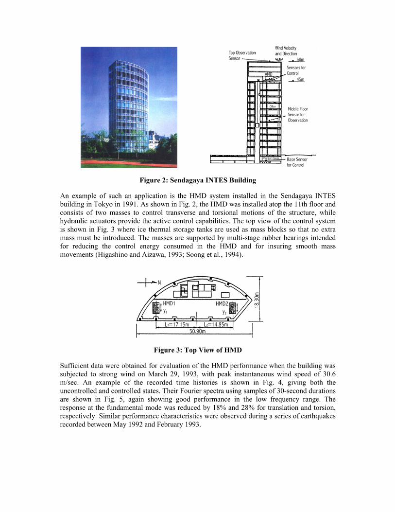
Figure 2: Sendagaya INTES Building
An example of such an application is the HMD system installed in the Sendagaya INTESbuilding in Tokyo in 1991. As shown in Fig. 2, the HMD was installed atop the 11th floor and consists of two masses to control transverse and torsional motions of the structure, whilehydraulic actuators provide the active control capabilities. The top view of the control systemis shown in Fig. 3 where ice thermal storage tanks are used as mass blocks so that no extramass must be introduced. The masses are supported by multi-stage rubber bearings intendedfor reducing the control energy consumed in the HMD and for insuring smooth massmovements (Higashino and Aizawa, 1993; Soong et al., 1994).
Figure 3: Top View of HMD
Sufficient data were obtained for evaluation of the HMD performance when the building was subjected to strong wind on March 29, 1993, with peak instantaneous wind speed of 30.6m/sec. An example of the recorded time histories is shown in Fig. 4, giving both theuncontrolled and controlled states. Their Fourier spectra using samples of 30-second durations are shown in Fig. 5, again showing good performance in the low frequency range. Theresponse at the fundamental mode was reduced by 18% and 28% for translation and torsion,respectively. Similar performance characteristics were observed during a series of earthquakes recorded between May 1992 and February 1993.
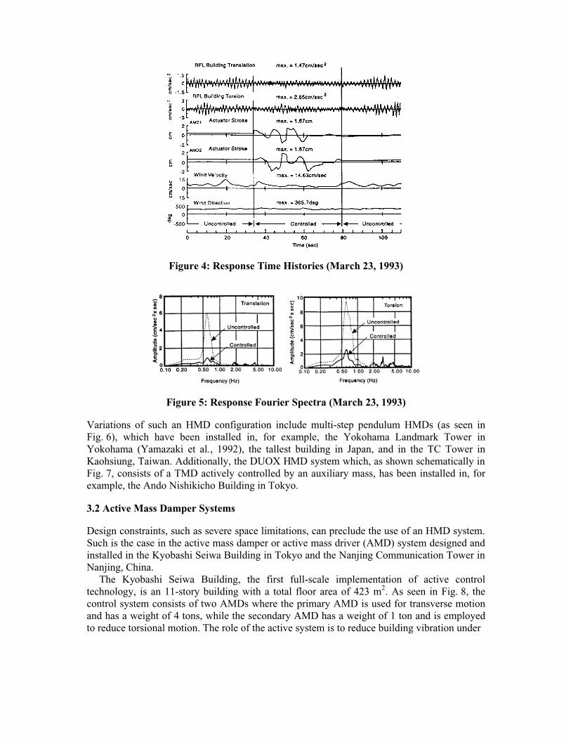
Figure 4: Response Time Histories (March 23, 1993)
Figure 5: Response Fourier Spectra (March 23, 1993)
Variations of such an HMD configuration include multi-step pendulum HMDs (as seen inFig. 6), which have been installed in, for example, the Yokohama Landmark Tower inYokohama (Yamazaki et al., 1992), the tallest building in Japan, and in the TC Tower inKaohsiung, Taiwan. Additionally, the DUOX HMD system which, as shown schematically in Fig. 7, consists of a TMD actively controlled by an auxiliary mass, has been installed in, forexample, the Ando Nishikicho Building in Tokyo.
3.2 Active Mass Damper Systems
Design constraints, such as severe space limitations, can preclude the use of an HMD system. Such is the case in the active mass damper or active mass driver (AMD) system designed and installed in the Kyobashi Seiwa Building in Tokyo and the Nanjing Communication Tower in Nanjing, China.
The Kyobashi Seiwa Building, the first full-scale implementation of active controltechnology, is an 11-story building with a total floor area of 423 m2. As seen in Fig. 8, thecontrol system consists of two AMDs where the primary AMD is used for transverse motionand has a weight of 4 tons, while the secondary AMD has a weight of 1 ton and is employedto reduce torsional motion. The role of the active system is to reduce building vibration under
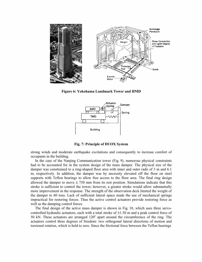
Figure 6: Yokohama Landmark Tower and HMD
Fig. 7: Principle of DUOX System
strong winds and moderate earthquake excitations and consequently to increase comfort ofoccupants in the building.
In the case of the Nanjing Communication tower (Fig. 9), numerous physical constraintshad to be accounted for in the system design of the mass damper. The physical size of thedamper was constrained to a ring-shaped floor area with inner and outer radii of 3 m and 6.1m, respectively. In addition, the damper was by necessity elevated off the floor on steelsupports with Teflon bearings to allow free access to the floor area. The final ring designallowed the damper to move ± 750 mm from its rest position. Simulations indicate that thisstroke is sufficient to control the tower; however, a greater stroke would allow substantiallymore improvement in the response. The strength of the observation deck limited the weight of the damper to 60 tons. Lack of sufficient lateral space made the use of mechanical springsimpractical for restoring forces. Thus the active control actuators provide restoring force aswell as the damping control forces.
The final design of the active mass damper is shown in Fig. 10, which uses three servo-controlled hydraulic actuators, each with a total stroke of ±1.50 m and a peak control force of 50 kN. These actuators are arranged 120o apart around the circumference of the ring. Theactuators control three degrees of freedom: two orthogonal lateral directions of motion andtorsional rotation, which is held to zero. Since the frictional force between the Teflon bearings
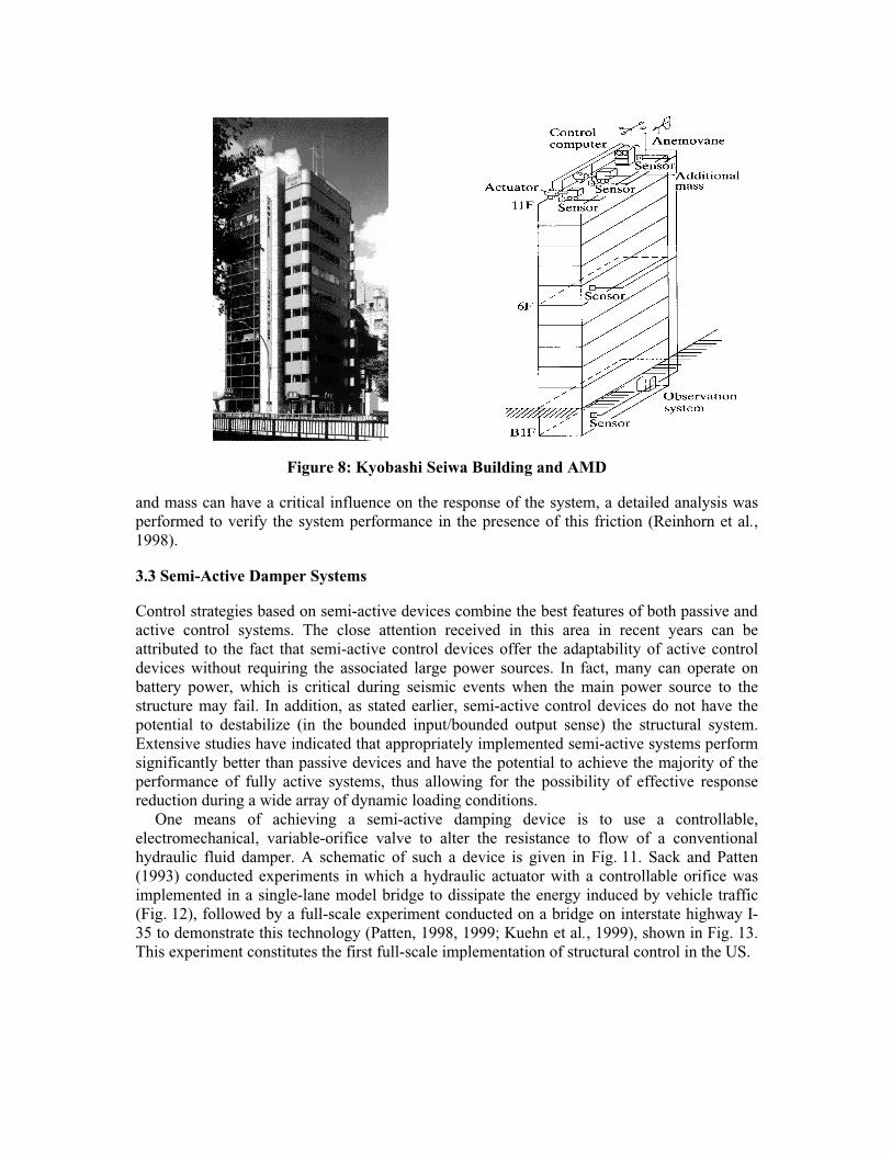
Figure 8: Kyobashi Seiwa Building and AMD
and mass can have a critical influence on the response of the system, a detailed analysis wasperformed to verify the system performance in the presence of this friction (Reinhorn et al.,1998).
3.3 Semi-Active Damper Systems
Control strategies based on semi-active devices combine the best features of both passive and active control systems. The close attention received in this area in recent years can beattributed to the fact that semi-active control devices offer the adaptability of active controldevices without requiring the associated large power sources. In fact, many can operate onbattery power, which is critical during seismic events when the main power source to thestructure may fail. In addition, as stated earlier, semi-active control devices do not have thepotential to destabilize (in the bounded input/bounded output sense) the structural system.Extensive studies have indicated that appropriately implemented semi-active systems performsignificantly better than passive devices and have the potential to achieve the majority of theperformance of fully active systems, thus allowing for the possibility of effective responsereduction during a wide array of dynamic loading conditions.
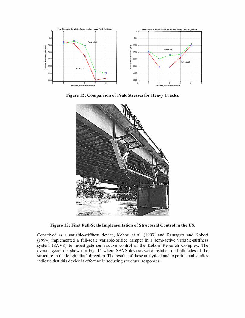
One means of achieving a semi-active damping device is to use a controllable,electromechanical, variable-orifice valve to alter the resistance to flow of a conventionalhydraulic fluid damper. A schematic of such a device is given in Fig. 11. Sack and Patten(1993) conducted experiments in which a hydraulic actuator with a controllable orifice wasimplemented in a single-lane model bridge to dissipate the energy induced by vehicle traffic(Fig. 12), followed by a full-scale experiment conducted on a bridge on interstate highway I-35 to demonstrate this technology (Patten, 1998, 1999; Kuehn et al., 1999), shown in Fig. 13.This experiment constitutes the first full-scale implementation of structural control in the US.
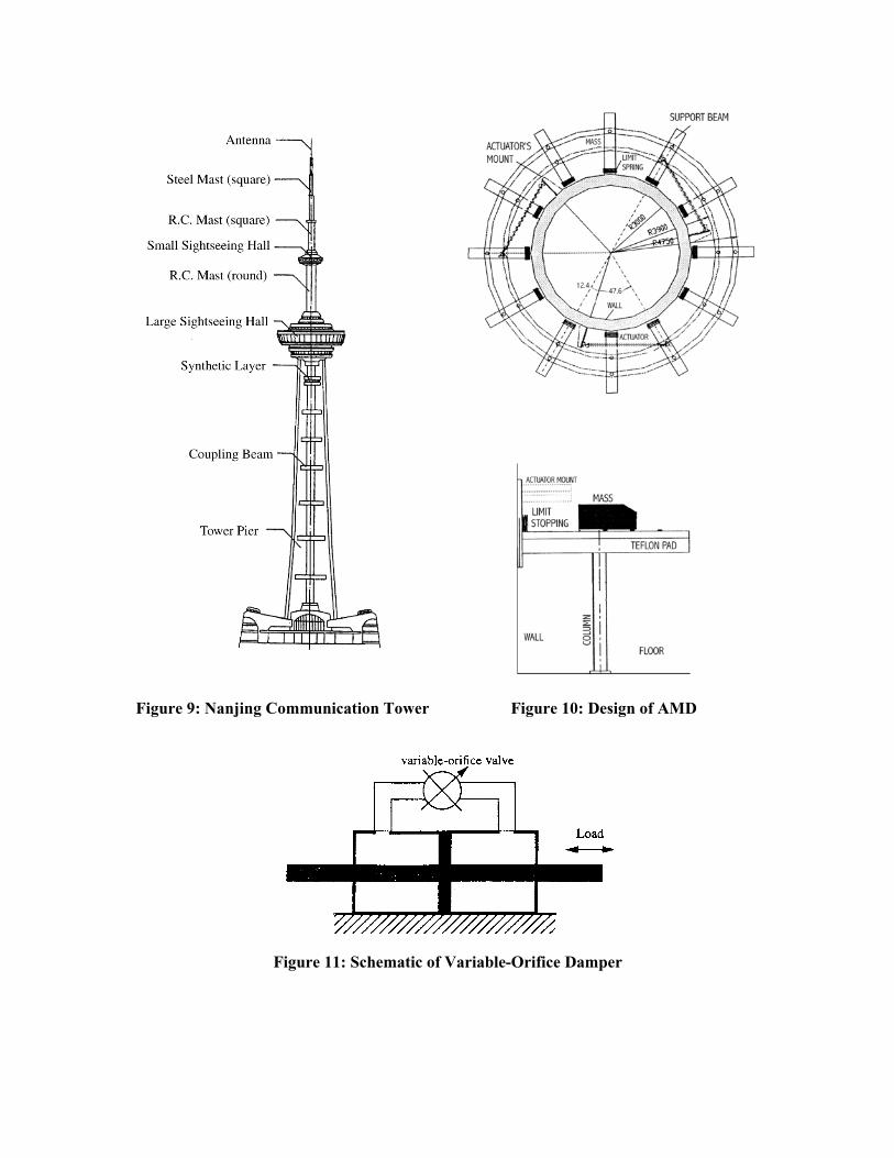
Figure 9: Nanjing Communication Tower Figure 10: Design of AMD
Figure 11: Schematic of Variable-Orifice Damper
0 1 2 3 4 5 6
-3500
-3000
-2500
-2000
-1500
-1000
-500
0Peak Stress on the Middle Cross Section, Heavy Truck /Left Lane
Dyn
amic
Ben
din
g S
tres
s (P
si)
Girder #, Eastern to Western
Controlled
No Control
0 1 2 3 4 5 6
-3500
-3000
-2500
-2000
-1500
-1000
-500
0Peak Stress on the Middle Cross Section, Heavy Truck /Right Lane
Dyn
amic
Ben
din
g S
tres
s (P
si)
Girder #, Eastern to Western
No Control
Controlled
Figure 12: Comparison of Peak Stresses for Heavy Trucks.
Figure 13: First Full-Scale Implementation of Structural Control in the US.
Conceived as a variable-stiffness device, Kobori et al. (1993) and Kamagata and Kobori(1994) implemented a full-scale variable-orifice damper in a semi-active variable-stiffnesssystem (SAVS) to investigate semi-active control at the Kobori Research Complex. Theoverall system is shown in Fig. 14 where SAVS devices were installed on both sides of thestructure in the longitudinal direction. The results of these analytical and experimental studies indicate that this device is effective in reducing structural responses.

Figure 14: SAVS System Configuration
Figure 15: Kajima Shizuoka Building and Semi-Active Hydraulic Damper
More recently, a semi-active damper system was installed in the Kajima Shizuoka Building in Shizuoka, Japan. As seen in Fig. 15, semi-active hydraulic dampers are installed inside thewalls on both sides of the building to enable it to be used as a disaster relief base in post-earthquake situations (Kobori, 1998; Kurata et al., 1999). Each damper contains a flowcontrol valve, a check valve and an accumulator, and can develop a maximum damping force of 1000 kN. Figure 16 shows a sample of the response analysis results based on one of theselected control schemes and several earthquake input motions with the scaled maximumvelocity of 50 cm/sec, together with a simulated Tokai wave. It is seen that both story shear

forces and story drifts are greatly reduced with control activated. In the case of the shearforces, they are confined within their elastic-limit values (indicated by E-limit) while, without control, they would enter the plastic range.
(a) With SAHD Control
(b) Without ControlFigure 16: Maximum Responses (El Centro, Taft and Hachinohe Waves with
50 cm/sec. and Assumed Tokai Waves)
3.4 Semi-active Controllable Fluid Dampers
Another class of semi-active devices uses controllable fluids, schematically shown in Fig. 17. In comparison with semi-active damper systems described above, an advantage ofcontrollable fluid devices is that they contain no moving parts other than the piston, whichmakes them simple and potentially very reliable.
The essential characteristics of controllable fluids is their ability to reversibly change froma free-flowing, linear viscous fluid to a semi-solid with a controllable yield strength in

milliseconds when exposed to an electric (for electrorheological (ER) fluids) or magnetic (for magnetorheological (MR) fluids) field.
In the case of magnetorheological fluids, they typically consist of micron-sized,magnetically polarizable particles dispersed in a carrier medium such as mineral or siliconeoil. When a magnetic field is applied to the fluid, particle chains form, and the fluid becomesa semi-solid and exhibits viscoplastic behavior. Transition to rheological equilibrium can beachieved in a few milliseconds, allowing construction of devices with high bandwidth.Additionally, Carlson and Weiss (1994) indicated that high yield stress of amagnetorheological fluid can be achieved and that magnetorheological fluids can operate attemperatures from –40oC to 150oC with only slight variations in the yield stress. Moreover,magnetorheological fluids are not sensitive to impurities such as are commonly encounteredduring manufacturing and usage, and little particle/carrier fluid separation takes place inmagnetorheological fluids under common flow conditions. Further, a wider choice ofadditives (surfactants, dispersants, friction modifiers, antiwear agents, etc.) can generally beused with magneto-rheological fluids to enhance stability, seal life, bearing life, and so on,since electrochemistry does not affect the magnetopolarization mechanism. Themagnetorheological fluid can be readily controlled with a low voltage (e.g., 12-24 V), current-driven power supply outputting only 1-2 amps.
Figure 17: Schematic of Controllable Fluid Damper
While no full-scale structural applications of magnetorheological devices have taken placeto date, their future for civil engineering applications appears to be bright. Spencer et al.(1996, 1997) and Dyke et al. (1996a-c, 1998) have conducted a number of pilot studies toassess the usefulness of magnetorheological dampers for seismic response reduction. Dyke etal. (1996a-c, 1998), Baker et al. (1999) and Spencer et al. (1999) have shown throughsimulations and laboratory experiments that the magnetorheological damper, used inconjunction with recently proposed acceleration feedback control strategies, significantlyoutperforms comparable passive configurations of the damper for seismic response reduction. In addition, Carlson and Spencer (1996) and Spencer et al. (1997, 1998) report on the designof a full-scale, 20-ton magnetorheological damper (see Fig. 18-19) showing that thistechnology is scalable to devices appropriate for civil engineering applications. At designvelocities, the dynamic range of forces produced by this device is over 10 (see Fig. 20), andthe total power required by the device is only 20-50 W.
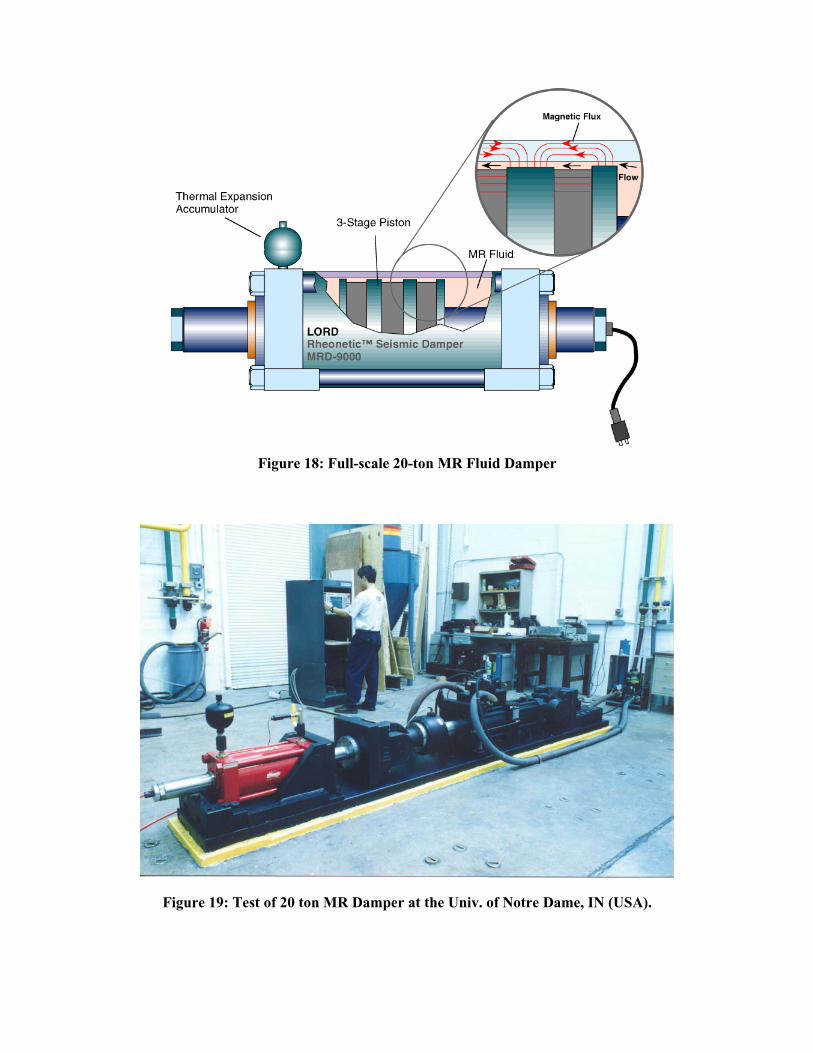
Figure 18: Full-scale 20-ton MR Fluid Damper
Figure 19: Test of 20 ton MR Damper at the Univ. of Notre Dame, IN (USA).
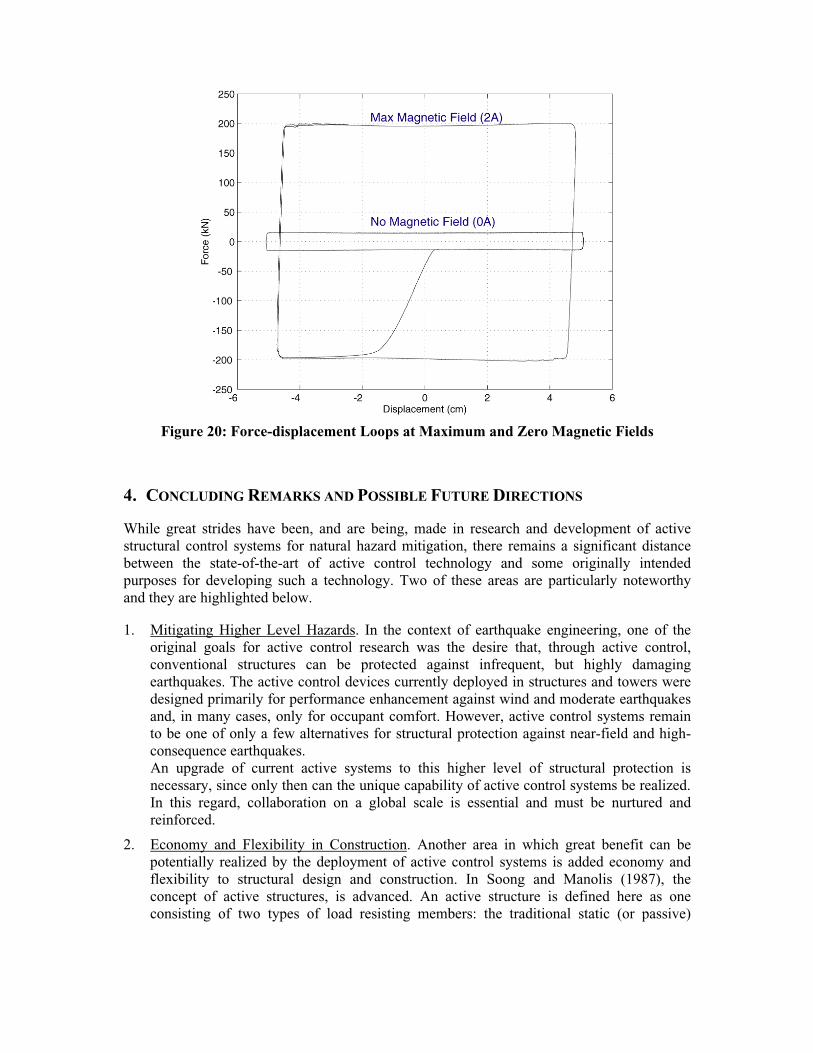
Figure 20: Force-displacement Loops at Maximum and Zero Magnetic Fields
4. CONCLUDING REMARKS AND POSSIBLE FUTURE DIRECTIONS
While great strides have been, and are being, made in research and development of activestructural control systems for natural hazard mitigation, there remains a significant distancebetween the state-of-the-art of active control technology and some originally intendedpurposes for developing such a technology. Two of these areas are particularly noteworthyand they are highlighted below.
1. Mitigating Higher Level Hazards. In the context of earthquake engineering, one of theoriginal goals for active control research was the desire that, through active control,conventional structures can be protected against infrequent, but highly damagingearthquakes. The active control devices currently deployed in structures and towers weredesigned primarily for performance enhancement against wind and moderate earthquakesand, in many cases, only for occupant comfort. However, active control systems remainto be one of only a few alternatives for structural protection against near-field and high-consequence earthquakes.An upgrade of current active systems to this higher level of structural protection isnecessary, since only then can the unique capability of active control systems be realized. In this regard, collaboration on a global scale is essential and must be nurtured andreinforced.
2. Economy and Flexibility in Construction. Another area in which great benefit can bepotentially realized by the deployment of active control systems is added economy andflexibility to structural design and construction. In Soong and Manolis (1987), theconcept of active structures, is advanced. An active structure is defined here as oneconsisting of two types of load resisting members: the traditional static (or passive)
members that are designed to support basic design loads, and dynamic (or active) members whose function is to augment the structure’s capability in resisting extraordinary dynamic loads. Their integration is done in an optimal fashion and produces a structure that is adaptive to changing environmental loads and usage. Note that an active structure is conceptually and physically different from a structure that is actively controlled, as in the cases described above. In the case of a structure with active control, a conventionally designed structure is supplemented by an active control device that is activated whenever necessary in order to enhance structural performance under extraordinary loads. Thus, the structure and the active control system are individually designed and optimized. An active structure, on the other hand, is one whose active and passive components are integrated and simultaneously optimized to produce a new breed of structural systems. This important difference makes the concept of active structures exciting and potentially revolutionary. Among many possible consequences, one can envision greater flexibilities which may lead to longer, taller, slender or more open structures and structural forms. To be sure, some progress has been made in this direction. For example, according to Seto (1998), the Kurusima Bridge in Shikoku area, Japan, was designed with the application of active vibration control as integrated structural components. Several modes of the bridge tower, which were anticipated to be excited by wind vortex, were carefully protected by appropriate controllers during the construction phase. It therefore made it possible for the tower of this bridge to be built much lighter and more slender than one following traditional design.
5. ACKNOWLEDGMENTS
The first author gratefully acknowledges the partial support of this work by the National Science Foundation under grant CMS-9900234 (Dr. S.C. Liu, Program Director) and the Lord Corporation. The second author wishes to acknowledge the generous support for this work received from the Multidisciplinary Center for Earthquake Engineering Research, Buffalo, NY. The authors are grateful to Professor T. Kobori of the Kobori Research Complex, Inc., Professor T. Fujita of the University of Tokyo, Professor A. Nishitani of Waseda University and Professor K.C. Chang of the National Taiwan University for their contributions, making this paper more complete on a global scale.
REFERENCES
Baker, G.A., Johnson, E.A., Spencer Jr., B.F. and Fujino, Y., 1999, “Modeling and semiactive damping of stay cables”, Proc.13th ASCE Engrg. Mech. Conf., Baltimore, Maryland, 6 pages (CD-ROM).
Carlson, J.D. and Spencer Jr., B.F., 1996, “Magneto-rheological fluid dampers for semi-active seismic control”, Proc. 3rd Int. Conf. on Motion and Vib. Control, Chiba Japan, III, pp. 35-40.
Carlson, J.D. and Weiss, K.D., 1994, “A growing attraction to magnetic fluids”, Machine Design, pp. 61-64.

Dyke, S.J., Spencer Jr., B.F., Quast, P. and Sain, M.K., 1995, “The role of control-structure interaction in protective system design”, J. Engrg. Mech., ASCE, 121(2), pp. 322-338.
Dyke, S.J., Spencer Jr., B.F., Sain, M.K. and Carlson, J.D., 1996a, “Experimental verification of semi-active structural control strategies using acceleration feedback”, Proc. 3rd Int. Conf. on Motion and Vib. Control, Chiba, Japan, III, pp. 291-296.
Dyke, S.J., Spencer Jr., B.F., Sain, M.K. and Carlson, J.D., 1996b, “Modeling and control of magnetorheological dampers for seismic response reduction”, Smart Mat. and Struct., 5, pp. 565-575.
Dyke, S.J., Spencer Jr., B.F., Sain, M.K. and Carlson, J.D., 1996c, “Seismic response reduction using magnetorheological dampers”, Proc. IFAC World Congress, San Francisco, CA.
Dyke, S.J., Spencer Jr., B.F., Sain, M.K. and Carlson, J.D., 1998, “An experimental study of MR dampers for seismic protection”, Smart Mat. and Struct., 7, pp. 693-703.
Fujino, Y., 1994, “Recent research and developments on control of bridges under wind and traffic excitations in Japan”, Proc. Int. Workshop on Struct. Control, pp. 144-150.
Higashino, M. and Aizawa, S., 1993, “Application of active mass damper system in actual buildings”, G.W. Housner and S.F. Masri (eds), Proc. Int. Workshop on Struct. Control,pp. 194-205, Los Angeles, CA.
Housner, G., Soong, T.T. and Masri, S.F., 1994a, “Second generation on active structural control in civil engineering”, Proc. 1st World Conf. on Struct. Control, pp. FA2:3-18, Pasadena, CA.
Housner, G.W., Bergman, L.A., Caughey, T.K., Chassiakos, A.G., Claus, R.O., Masri, S.F., Skelton, R.E., Soong, T.T., Spencer Jr., B.F. and Yao, T.P., 1997, “Structural control: Past, present, and future”, J. Engrg. Mech., ASCE, 123(9), pp. 897-971.
Housner, G.W., Masri, S.F. and Chassiakos, A.G. (eds), 1994b, Proc. 1st World Conf. on Struct. Control, Pasadena, CA.
Kamagata, S. and Kobori, T., 1994, “Autonomous adaptive control of active variable stiffness systems for seismic ground motion”, Proc. 1st World Conf. on Struct. Control, pp. TA4:33-42, Pasadena, CA.
Kobori, T., 1994, “Future direction on research and development of seismic-response-controlled structure”, Proc. 1st World Conf. on Struct. Control, Panel, pp. 19-31, Pasadena, CA.
Kobori, T., 1998, “Mission and perspective towards future structural control research”, Proc.of 2nd World Conf. in Struct. Control, 1, pp. 25-34, Kyoto, Japan.
Kobori, T., Inou, Y., Seto, K., Iemura, H. and Nishitani, A. (eds.), 1998, Proc. 2nd World Conf. on Struct. Control, Kyoto, Japan.

Kobori, T., Takahashi, M., Nasu, T., Niwa, N. and Ogasawara, K., 1993, “Seismic response controlled structure with active variable stiffness system”, Earthquake Engrg. and Struct. Dyn., 22, pp. 925-941.
Kuehn, J., Song, G. and Sun, J., 1999, “Experimental Verification of a NON-Protruding Intelligent Stiffener for Bridges (ISB)”, Proc. Int. Post-SMiRT Conf. Seminar on Seismic Isolation, Passive Energy, Dissipation and Active Control of Vibrations of Structures, Cheju, Korea, August 23-25, 1999.
Kurata, N., Kobori, T., Takahashi, M., Niwa, N. and Midorikawa, H., 1999, “Actual seismic response controlled building with semi-active damper system,” Earthquake Engrg. and Struct. Dyn., in press.
Patten, W., Sun, J., Li, G., Kuehn, J., and Song, G.,, 1999, “Field Test of an Intelligent Stiffener for Bridges at the I-35 Walnut Creek Bridge”. Earthquake Engrg. and Struct. Dyn.,Vol. 28, No. 2, pp. 109-126.
Patten, W.N., 1998, “The I-35 Walnut Creek Bridge: An intelligent highway bridge via semi-active structural control”, Proc. 2nd World Conf. on Struct. Control, 1, pp. 427-436, Kyoto, Japan.
Reinhorn, A.M., Soong, T.T., Helgeson, R.J., Riley, M.A. and Cao, H., 1998, “Analysis, design and implementation of an active mass damper for a communication tower”, Proc. 2nd
World Conf. on Struct. Control, 3, pp. 1727-1736, Kyoto, Japan.
Sack, R.L. and Patten, W, 1993, “Semiactive hydraulic structural control”, Proc. Int. Workshop on Struct. Control, USC Publication No. CE-9311, pp. 417-431, Honolulu, Hawaii.
Seto, K. 1998, “Modeling and active vibration control of flexible structures”, Proc. of 2nd
World Conf. on Struct. Control, 1, pp. 15-24, Kyoto, Japan.
Soong, T.T., 1990, Active Structural Control: Theory and Practice, Longman, England and Wiley, New York, NY.
Soong, T.T. and Manolis, G.D., 1987, “Active structures”, J. Struct. Engrg., ASCE, 113(11), pp. 2290-2301.
Soong, T.T., Reinhorn, A.M., Aizawa, S. and Higashino, M., 1994, “Recent structural applications of active control technology”, J. Struct. Control, 1(2), pp. 5-21.
Spencer Jr., B.F. and Sain, M.K., 1997, “Controlling buildings: A new frontier in feedback”,IEEE Control Systems Magazine: Special Issue on Emerging Technologies, 17(6), pp. 19-35.
Spencer Jr., B.F., Carlson, J.D., Sain, M.K. and Yang, G., 1997, “On the current status of magnetorheological dampers: Seismic protection of full-scale structures”, Proc. American Control Conf., pp. 458-462, Albuquerque, NM.
Spencer Jr., B.F., Dyke, S.J., Sain, M.K. and Carlson, J.D., 1996, “Idealized model of a magnetorheological damper”, Proc. 12th Conf. on Analysis and Computation, ASCE, pp. 361-370, Chicago, IL.
Spencer Jr., B.F., Dyke, S.J., Sain, M.K. and Carlson, J.D., 1997, “Phenomenological model of a magnetorheological damper”, J. Engrg. Mech., ASCE, 123(3), pp. 230-238.
Spencer Jr., B.F., Johnson, E.A. and Ramallo, J.C., 1999, “Smart isolation for seismic control”, Proc. Pioneering Int. Symp. on Motion and Vib. Control in Mechatronics, Tokyo, Japan, pp. 169-174.
Spencer Jr., B.F., Yang, G., Carlson, J.D. and Sain, M.K., 1998, “Smart dampers for seismic protection of structures: A full-scale study”, Proc. of 2nd World Conf. on Struct. Control, 1, pp. 417-426, Kyoto, Japan.
Suhardjo, J., Spencer Jr., B.F. and Sain, M.K., 1990, “Feedback-feedforward control of structures under seismic excitation”, Struct. Safety, 8, pp. 69-89.
Yamazaki, S., Nagata, N., and Abiru, H., 1992, “Tuned active dampers installed in the Minato Mirai (MM) 21 Landmark Tower in Yokohama”, J. Wind Engrg. and Indust. Aerodyn., 43, pp. 1937-1948.