neutronics and tritium breeding capability for liquid metal-based … · neutronics and tritium...
TRANSCRIPT

Neutronics and Tritium Breeding Capability for Liquid Metal-Based Blanket (DCLL)
L. El-Guebaly Fusion Technology Institute
University of Wisconsin-Madison http://fti.neep.wisc.edu/UWNeutronicsCenterOfExcellence
Contributors: S. Malang (Consultant), L. Waganer (Consultant), A. Rowcliffe (ORNL)
FESAC TEC 2017 Panel Community Input Workshop
Rockville, MD May 30 – June 1, 2017

2
Scope and Motivation
• Transition from ITER to fusion DEMO and power plant requires development of tritium breeding blanket to generate tritium (T) in unprecedented large quantities to sustain the plasma operation.
• Dual-coolant lead lithium (DCLL) blanket is prominent option for future US devices: tokamaks, spherical torii, and stellarators.
• This talk : – Provides brief overview of breeding capability of lead lithium (PbLi) breeder under
typical power plant operating conditions – Identifies uncertainties in tritium breeding prediction – Outlines critical and design variables that determine and control breeding level – Suggests developing several technologies to assure T self-sufficiency and mitigate
risk of shortage or surplus of T – Mentions briefly related transforming technologies:
– Tritium extraction – Additive manufacturing and nano-fabrication – Advanced ODS alloys.

3
Nuclear Assessment Involves Three Closely-Related Tasks
Neutronics: – Neutron wall loading distribution: peak
and average values – Tritium breeding ratio (TBR) for T-self
sufficiency – Radial and poloidal nuclear heating
distribution (for thermal hydraulic analysis)
– Nuclear energy multiplication (for power balance)
– Radiation damage to structural materials (dpa, He production, H production)
– Service lifetimes of all components based on neutron dose (for replacement frequency and cost).
Shielding: – Shielding of permanent
components (for protection against radiation)
– Radial and vertical build definition (for physics code, CAD drawings, and systems code analysis)
– Neutron streaming through assembly gaps and penetrations (for protection of external components)
– Bioshield specifications.
Activation: – Radioactive product inventory (for
safety, environmental, and licensing assessments)
– Environmental impact of FNSF and radwaste classification
– Decay heat (for thermal response of components during LOCA/LOFA events)
– Biological dose (for maintenance crew, workers and public protection).
This talk focuses on T breeding issues – a subtask of neutronics assessment for fusion devices (such as power plants, DEMO, and FNSFs) seeking T self-sufficiency
Refs: L. El-Guebaly, “Progressive Steps Towards Integral Nuclear Assessments for Fusion Devices,” Transactions of ANS winter meeting, Washington, DC, November 10-14, 2013. Laila El-Guebaly, “Overview of ARIES Nuclear Assessments: Neutronics, Shielding, and Activation,” Progress in Nuclear Science and Technology 4, 118-121 (2014). DOI: 10.15669.
4
Tritium Resources and Economics
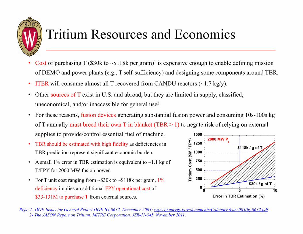
• Cost of purchasing T ($30k to ~$118k per gram)1 is expensive enough to enable defining mission of DEMO and power plants (e.g., T self-sufficiency) and designing some components around TBR.
• ITER will consume almost all T recovered from CANDU reactors (~1.7 kg/y).
• Other sources of T exist in U.S. and abroad, but they are limited in supply, classified, uneconomical, and/or inaccessible for general use2.
• For these reasons, fusion devices generating substantial fusion power and consuming 10s-100s kg of T annually must breed their own T in blanket (TBR > 1) to negate risk of relying on external supplies to provide/control essential fuel of machine.
• TBR should be estimated with high fidelity as deficiencies in TBR prediction represent significant economic burden.
• A small 1% error in TBR estimation is equivalent to ~1.1 kg of T/FPY for 2000 MW fusion power.
• For T unit cost ranging from ~$30k to ~$118k per gram, 1% deficiency implies an additional FPY operational cost of $33-131M to purchase T from external sources.
0
250
500
750
1000
1250
1500
0 5 10Tr
itium
Cos
t ($M
/ FP
Y)
Error in TBR Estimation (%)
$30k / g of T
$118k / g of T
2000 MW Pf
Refs: 1- DOE Inspector General Report DOE IG-0632, December 2003; www.ig.energy.gov/documents/CalenderYear2003/ig-0632.pdf. 2- The JASON Report on Tritium. MITRE Corporation, JSR-11-345, November 2011.
5
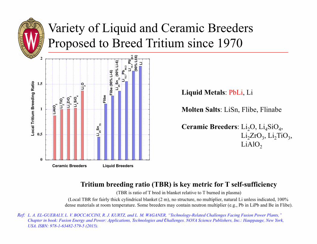
Variety of Liquid and Ceramic Breeders Proposed to Breed Tritium since 1970
Tritium breeding ratio (TBR) is key metric for T self-sufficiency (TBR is ratio of T bred in blanket relative to T burned in plasma)
(Local TBR for fairly thick cylindrical blanket (2 m), no structure, no multiplier, natural Li unless indicated, 100% dense materials at room temperature. Some breeders may contain neutron multiplier (e.g., Pb in LiPb and Be in Flibe).
0
0.5
1
1.5
2
1 2 3 4 5 6 7 8 9 10 11 12 13 14 15
Loca
l Trit
ium
Bre
edin
g R
atio
Ceramic Breeders Liquid Breeders
Li15
.7Pb
84.3
Li4Si
O4
Li2O
Li2Zr
O3
Li2Ti
O3
LiA
lO2
Li25
Sn75
Flib
e (9
0% L
i-6)
Li25
Sn75
(90%
Li-6
)
Li15
.7Pb
84.3
(90%
Li-6
)
Flib
e
Li
Liquid Metals: PbLi, Li
Molten Salts: LiSn, Flibe, Flinabe
Ceramic Breeders: Li2O, Li4SiO4, Li2ZrO3, Li2TiO3, LiAlO2
Ref: L. A. EL-GUEBALY, L. V. BOCCACCINI, R. J. KURTZ, and L. M. WAGANER, “Technology-Related Challenges Facing Fusion Power Plants,” Chapter in book: Fusion Energy and Power: Applications, Technologies and Challenges. NOVA Science Publishers, Inc.: Hauppauge, New York, USA. ISBN: 978-1-63482-579-5 (2015).

6
PbLi* – Most Popular Liquid Metal Worldwide
• In US, PbLi is preferred breeder for future devices: Fusion Nuclear Science Facilities (FNSF) and power plants based on tokamak, spherical torus, and stellarator concepts.
• In Europe, EUROfusion is currently examining dual coolant lead lithium (DCLL), water-cooled lead lithium (WCLL), and He-cooled lead lithium (HCLL) blankets for EU DEMO and/or power plants.
• Japan prefers molten salts (Flibe/Flinabe) with some interest in PbLi blankets.
• China is developing both HCLL and DCLL blankets for fusion applications.
• Most PbLi-based blankets are supplemented with water or helium coolant, as in WCLL, HCLL, and DCLL.
* Refs: S. Malang et al. (2011). “Development of the lead lithium (DCLL) blanket concept,’’ Fusion Science and Technology, 60, 249. L. A. EL-GUEBALY, L. V. BOCCACCINI, R. J. KURTZ, and L. M. WAGANER, “Technology-Related Challenges Facing Fusion Power Plants,” Chapter in book: Fusion Energy and Power: Applications, Technologies and Challenges. NOVA Science Publishers, Inc.: Hauppauge, New York, USA. ISBN: 978-1-63482-579-5 (2015).
Laila A. El-Guebaly, “Fifty Years of Magnetic Fusion Research (1958-2008): Brief Historical Overview and Discussion of Future Trends.” Energies 2010, 3 (6), 1067-1086 (June 2010). Available at: http://www.mdpi.com/1996-1073/3/6/
7
PbLi: Most Popular Liquid Metal Worldwide (Cont.) (US Tokamaks)
PbLi Li CB
Russia
Japan
China
Japan
Japan
EU
Japan
Japan
Japan
Japan
Japan
Russia
69 70 71 72 73 74 75 76 77 78 79 80 81 82 83 84 85 86 87 88 89 90 91 92 93 94 95 96 97 98 99 00 01 02 03 04 05 06 07 08 09 10 11 12 13
ARIES-ACT Aggressive and Conservative Tokamaks (UCSD)
DEMO-S steady state DEMO
SlimCS Compact low-A DEMO
FDS-II China power plant
VECTOR VEry Compact TOkamak Reactor
DEMO2001
PPCS Conceptual Study of Fusion Power Plants
ARIES-AT Advanced Tokamak (UCSD)
A-SSTR2 Combine advantages of A-SSTR and DREAM
ARIES-RS Reversed-Shear tokamak (UCSD)
A-SSTR Advanced Steady State Tokamak
DREAM Drastically Easy Maintenance Tokamak
CREST Compact Reversed Shear Tokamak
PULSAR-I/II pulsed tokamak (UCSD)
ARIES-IV Second-stability tokamak (UCLA)
ARIES-II Second-stability tokamak (UCLA)
ARIES-III D-3He-fuelled tokamak (UCLA)
SSTR steady state tokamak
ARIES-I First-stability tokamak (UCLA)
Apollo D-3He Fuelled Tokamak (UW)
Wildcat catalyzed D-D tokamak (ANL)
STARFIRE Commercial Tokamak Fusion Power Plant (ANL)
NUWMAK University of Wisconsin Tokamak (UW)
TVE-2500 high temperature power plant with direct conversion
UWMAK-III University of Wisconsin Tokamak (UW)
UWMAK-II University of Wisconsin Tokamak (UW)
A Fusion Power Plant (PPPL)
UWMAK-I University of Wisconsin Tokamak (UW)
Premak University of Wisconsin Tokamak (UW)
69 70 71 72 73 74 75 76 77 78 79 80 81 82 83 84 85 86 87 88 89 90 91 92 93 94 95 96 97 98 99 00 01 02 03 04 05 06 07 08 09 10 11 12 13
calendar year
Tokamak (29)
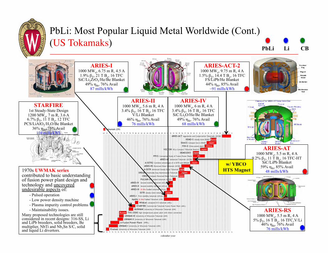
1970s UWMAK series contributed to basic understanding of fusion power plant design and technology and uncovered undesirable aspects of:
- Pulsed operation - Low power density machine - Plasma impurity control problems - Maintainability issues.
Many proposed technologies are still considered in recent designs: 316-SS, Li and LiPb breeders, solid breeders, Be multiplier, NbTi and Nb3Sn S/C, solid and liquid Li divertors.
ARIES-II 1000 MWe, 5.6 m R, 4 A 3.4% βT, 16 T Bc, 16 TFC
V/Li Blanket 46% ηth, 76% Avail
76 mills/kWh
ARIES-RS 1000 MWe, 5.5 m R, 4 A
5% βT, 16 T Bc, 16 TFC,V/Li 46% ηth, 76% Avail
76 mills/kWh
ARIES-IV 1000 MWe, 6 m R, 4 A
3.4% βT, 16 T Bc, 16 TFC SiC/Li2O/He/Be Blanket
49% ηth, 76% Avail 68 mills/kWh
ARIES-AT 1000 MWe, 5.5 m R, 4 A
9.2% βT, 11 T Bc, 16 TFC-HT SiC/LiPb Blanket
59% ηth, 85% Avail 48 mills/kWh
STARFIRE 1st Steady-State Design 1200 MWe, 7 m R, 3.6 A 6.7% βT, 11 T Bc, 12 TFC
PCS/LiAlO2/H2O/Be Blanket 36% ηth, 75% Avail
110 mills/kWh
ARIES-I 1000 MWe, 6.75 m R, 4.5 A 1.9% βT, 21 T Bc, 16 TFC
SiC/Li2ZrO3/He/Be Blanket 49% ηth, 76% Avail
87 mills/kWh
ARIES-ACT-2 1000 MWe, 9.75 m R, 4 A
1.5% βT, 14.4 T Bc, 16 TFC FS/LiPb/He Blanket 44% ηth, 85% Avail
~91 mills/kWh
w/ YBCO HTS Magnet
8
PbLi: Most Popular Liquid Metal Worldwide (Cont.) (International Tokamaks)
PbLi Li CB
Russia
Japan
China
Japan
Japan
EU
Japan
Japan
Japan
Japan
Japan
Russia
69 70 71 72 73 74 75 76 77 78 79 80 81 82 83 84 85 86 87 88 89 90 91 92 93 94 95 96 97 98 99 00 01 02 03 04 05 06 07 08 09 10 11 12 13
ARIES-ACT Aggressive and Conservative Tokamaks (UCSD)
DEMO-S steady state DEMO
SlimCS Compact low-A DEMO
FDS-II China power plant
VECTOR VEry Compact TOkamak Reactor
DEMO2001
PPCS Conceptual Study of Fusion Power Plants
ARIES-AT Advanced Tokamak (UCSD)
A-SSTR2 Combine advantages of A-SSTR and DREAM
ARIES-RS Reversed-Shear tokamak (UCSD)
A-SSTR Advanced Steady State Tokamak
DREAM Drastically Easy Maintenance Tokamak
CREST Compact Reversed Shear Tokamak
PULSAR-I/II pulsed tokamak (UCSD)
ARIES-IV Second-stability tokamak (UCLA)
ARIES-II Second-stability tokamak (UCLA)
ARIES-III D-3He-fuelled tokamak (UCLA)
SSTR steady state tokamak
ARIES-I First-stability tokamak (UCLA)
Apollo D-3He Fuelled Tokamak (UW)
Wildcat catalyzed D-D tokamak (ANL)
STARFIRE Commercial Tokamak Fusion Power Plant (ANL)
NUWMAK University of Wisconsin Tokamak (UW)
TVE-2500 high temperature power plant with direct conversion
UWMAK-III University of Wisconsin Tokamak (UW)
UWMAK-II University of Wisconsin Tokamak (UW)
A Fusion Power Plant (PPPL)
UWMAK-I University of Wisconsin Tokamak (UW)
Premak University of Wisconsin Tokamak (UW)
69 70 71 72 73 74 75 76 77 78 79 80 81 82 83 84 85 86 87 88 89 90 91 92 93 94 95 96 97 98 99 00 01 02 03 04 05 06 07 08 09 10 11 12 13
calendar year
Tokamak (29)
8
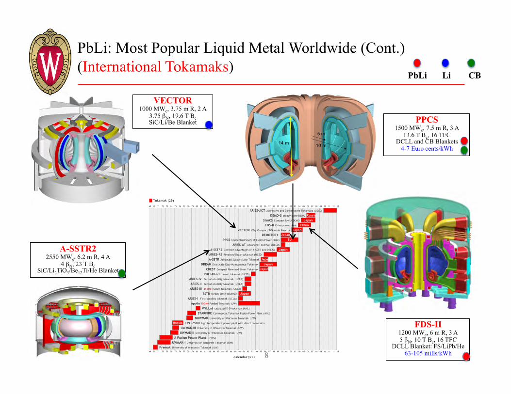
5 m
10 m14 m
PPCS 1500 MWe, 7.5 m R, 3 A
13.6 T Bc, 16 TFC DCLL and CB Blankets
4-7 Euro cents/kWh
VECTOR 1000 MWe, 3.75 m R, 2 A
3.75 βN, 19.6 T Bc SiC/Li/Be Blanket
FDS-II 1200 MWe, 6 m R, 3 A 5 βN, 10 T Bc, 16 TFC
DCLL Blanket: FS/LiPb/He 63-105 mills/kWh
A-SSTR2 2550 MWe, 6.2 m R, 4 A
4 βN, 23 T Bc SiC/Li2TiO3/Be12Ti/He Blanket

9
PbLi: Most Popular Liquid Metal Worldwide (Cont.) (Spherical Torii)
PbLi Li CB
9
ST-UK 1224 MWe, 3.4 m R, 1.4 A
58% βT, 88% fBS, 21 MW/m2 Div Peak HF
7.6 T Bc, 16 Coils 250 MW Joule Losses
39% Recirculating Power Fraction FS/Li4SiO4/He/Be Blanket
43% ηth Divertor: Flowing SiC Pebbles
ARIES-ST 1000 MWe, 3.2 m R, 1.6 A
50% βT, 96% fBS 31 MW/m2 Div Peak HF
7.4 T Bc, Continuous Coils 330 MW Joule Losses
34% Recirculating Power Fraction DCLL Blanket: FS/LiPb/He
45% ηth, 76% Avail Divertor: Inclined OB Plate
and W IB plate 81 mills/kWh
First DCLL Blanket
Design (1997)

10
PbLi: Most Popular Liquid Metal Worldwide (Cont.) (Stellarators)
PbLi Li CB
10
ASRA-6C 1620 MWe, 5 FP, 20 m R, 12.5 A
5% βT, 10.4 T Bc, 30 Coils FS/LiPb Blanket
40% ηth
SPPS 1000 MWe, 4 FP, 14 m R, 8.5 A
5% βT, 14.5 T Bc, 32 Coils V/Li Blanket
46% ηth, 76% Avail 75 mills/kWh
ARIES-CS 1000 MWe, 3 FP, 7.75 m R, 4.5 A
6.4% βT, 15 T Bc, 18 Coils DCLL Blanket: FS/LiPb/He
42% ηth, 85% Avail 61 mills/kWh
HSR 3 GW Pf, 4 FP, 18 m R, 8.6 A
?% βT, 10 T Bc, 40 Coils FS/LiPb Blanket
~35% ηth
FFHR2m2
1300 MWe, 10 FP, 16 m R, 5.7 A 4.1% βT, 13 T Bc, Continuous Coils
FS/Flibe/Be Blanket 87 mills/kWh
Ports
Plasma Blanket & Shield
Support ring
UWTOR-M 1840 MWe, 6 FP, 24 m R, 14 A
6% βT, 11.6 T Bc, 18 Coils FS/LiPb Blanket
40% ηth

11
PbLi: Preferred Breeder for Future US Fusion Devices
FDF
+ Supporting R&D: Blanket development program,
Materials Testing Facility, PMI Facility, code development
and simulations, etc.
1st Power Plant (in 2050 or beyond)
Tokamak (ARIES-ACT),
Spherical Tokamak (ARIES-ST),
or Stellarator (ARIES-CS)
Tokamak based on available physics & Tech with pre-phase
for component testing; Qeng= 3-5
2 Phases DEMO-II ?!
ST-FNSF, HTS-FNSF
FESS-FNSF
Stell-FNSF
?
US
EU, JA, KO
DEMO
China
ITER + other Tokamaks
(JET, JT-60U, KSTAR, EAST)
NSTX, Pegasus, MAST
HSX, W7-X, LHD
DEMO
CFETR
DEMO
PbLi Li CB
Worldwide Pathways to Fusion Energy
Fusion Nuclear Science Facility (to develop technology for US DEMO)
Tokamak, ST, or Stellarator?
Ref: L. El-Guebaly, A. Rowcliffe, J. Menard, T. Brown, “TBM/MTM for HTS-FNSF: An Innovative Testing Strategy to Qualify/Validate Fusion Technologies for U.S. DEMO,” Energies 2016, 9, 632; doi:10.3390/en9080632: http://www.mdpi.com/1996-1073/9/8/632/pdf.

12
Transition From Experiments to Power Plants Requires Blankets to Generate T in Unprecedented Large Quantities
• FNSF, DEMO, and power plants generating 2-3 GW fusion power, should breed all T required to fuel plasma and sustain operation:
55.6 kg of T per GW of fusion power, per full power year of operation
Typical DCLL Blanket Design Flowing PbLi
SiC FCI
He Cooled Cooling Channel
• Prominent PbLi-based blanket concept in US is DCLL blanket1: - First developed in US by Malang in1990s for ARIES-
ST power plant. - Employs pressurized helium coolant (at 8-10 MPa)
and reduced-activation ferritic/martensitic (RAFM) steel structure.
- Flow channel insert2 (FCI) is essential to electrically and thermally insulate hot PbLi breeder/coolant from RAFM steel.
- Silicon carbide is prime candidate for FCI.
Refs: 1-S. Malang et al. (2011).’’ Fusion Science and Technology, 60, 249. 2- Sharafat, S., et al. (2009). Fusion Science and Technology, 56, 883.
13
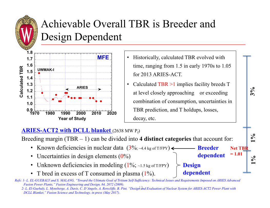
Achievable Overall TBR is Breeder and Design Dependent
0.91.01.11.21.31.41.51.61.71.8
1970 1980 1990 2000 2010 2020
Cal
cula
ted
TBR
Year of Study
ARIES
UWMAK-I
MFE
ARIES-ACT2 with DCLL blanket (2638 MW Pf) Breeding margin (TBR – 1) can be divided into 4 distinct categories that account for: • Known deficiencies in nuclear data (3%; ~4.4 kg of T/FPY) • Uncertainties in design elements (0%) • Unknown deficiencies in modeling (1%; ~1.5 kg of T/FPY) • T bred in excess of T consumed in plasma (1%).
Breeder dependent
Design dependent
• Historically, calculated TBR evolved with time, ranging from 1.5 in early 1970s to 1.05 for 2013 ARIES-ACT.
• Calculated TBR >1 implies facility breeds T at level closely approaching or exceeding combination of consumption, uncertainties in TBR prediction, and T holdups, losses, decay, etc.
3%
1%
1%
Net TBR = 1.01
Refs: 1- L. EL-GUEBALY and S. MALANG, “Toward the Ultimate Goal of Tritium Self-Sufficiency: Technical Issues and Requirements Imposed on ARIES Advanced Fusion Power Plants,” Fusion Engineering and Design, 84, 2072 (2009).
2- L. El-Guebaly, L. Mynsberge, A. Davis, C. D’Angelo, A. Rowcliffe, B. Pint, “Design and Evaluation of Nuclear System for ARIES-ACT2 Power Plant with DCLL Blanket,” Fusion Science and Technology, in press (May 2017).
14
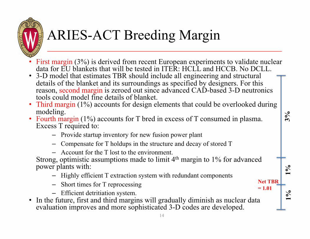
ARIES-ACT Breeding Margin
• First margin (3%) is derived from recent European experiments to validate nuclear data for EU blankets that will be tested in ITER: HCLL and HCCB. No DCLL.
• 3-D model that estimates TBR should include all engineering and structural details of the blanket and its surroundings as specified by designers. For this reason, second margin is zeroed out since advanced CAD-based 3-D neutronics tools could model fine details of blanket.
• Third margin (1%) accounts for design elements that could be overlooked during modeling.
• Fourth margin (1%) accounts for T bred in excess of T consumed in plasma. Excess T required to:
– Provide startup inventory for new fusion power plant – Compensate for T holdups in the structure and decay of stored T – Account for the T lost to the environment.
Strong, optimistic assumptions made to limit 4th margin to 1% for advanced power plants with:
– Highly efficient T extraction system with redundant components – Short times for T reprocessing – Efficient detritiation system.
• In the future, first and third margins will gradually diminish as nuclear data evaluation improves and more sophisticated 3-D codes are developed.
3%
1%
1%
Net TBR = 1.01
• Several design elements could control breeding level of DCLL blanket: – Blanket coverage and shape (full banana for US designs or small modules as in EU
designs) – FW thickness and structural content – Design of side/top/bottom/back walls – Choice of coolant and cooling channel layout – FCI thickness – W stabilizing shell dimension and location – H/CD aperture size and orientation – Torroidal width of assembly gaps.
• UW developed novel stepwise approach that allows adding various blanket components “step-by-step” to understand how individual design elements degrade TBR of DCLL blanket and what conditions or changes are more damaging/enhancing to breeding.
• High fidelity TBR computations would have never been established without developing most innovative computational tool: state-of-the-art DAGMC code by UW couples detailed CAD geometry of blanket internals with 3-D MCNP code.
Refs: L. . El-Guebaly, A. Jaber, and S. Malang, “State-of-the-Art 3-D Assessment of Elements Degrading the TBR of the ARIES DCLL Blanket," Fusion Science and Technology 61, #4 (May 2012) 321-331. P. P. H. WILSON et al., “Acceleration Techniques for the Direct Use of CAD-Based Geometry in Fusion Neutronics,” Fusion Engineering and Design, 85, 10-12, 1759 (2010). “DAGMC Users Guide,” University of Wisconsin-Madison Fusion Technology Institute (2008); http://svalinn.github.io/DAGMC/usersguide/
Design Variables That Control TBR
16
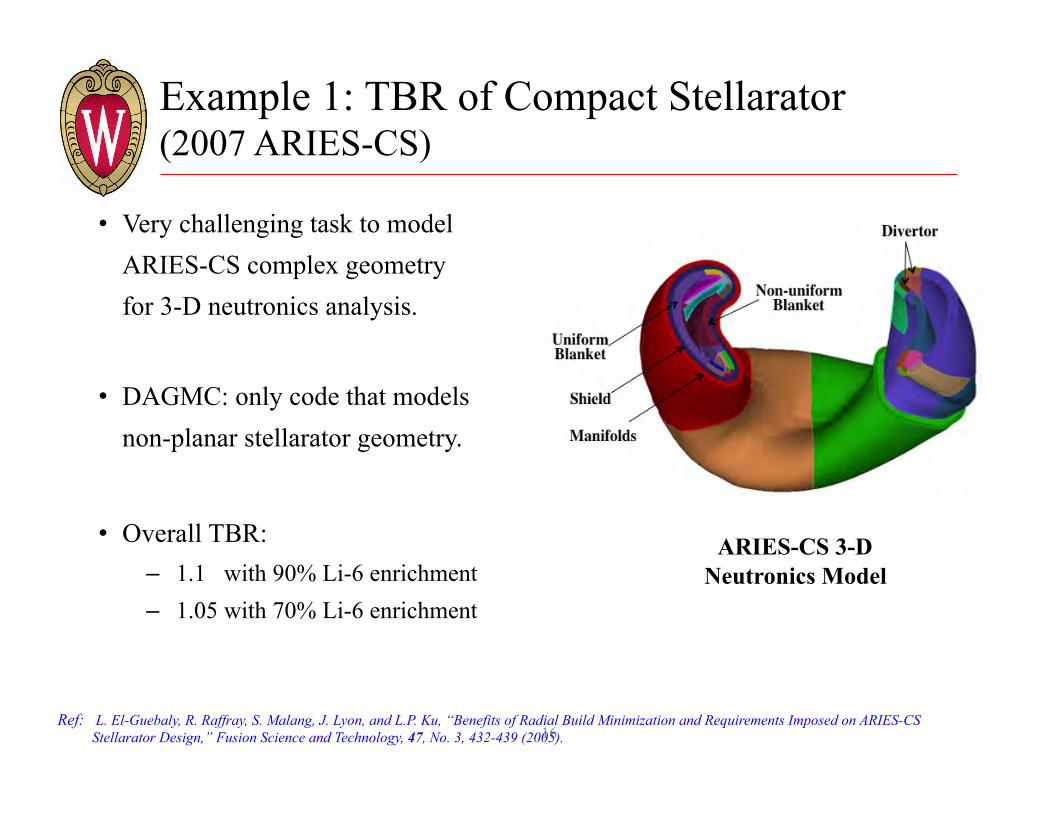
Example 1: TBR of Compact Stellarator (2007 ARIES-CS)
• Very challenging task to model ARIES-CS complex geometry for 3-D neutronics analysis.
• DAGMC: only code that models non-planar stellarator geometry.
• Overall TBR: – 1.1 with 90% Li-6 enrichment – 1.05 with 70% Li-6 enrichment
ARIES-CS 3-D Neutronics Model
Ref: L. El-Guebaly, R. Raffray, S. Malang, J. Lyon, and L.P. Ku, “Benefits of Radial Build Minimization and Requirements Imposed on ARIES-CS Stellarator Design,” Fusion Science and Technology, 47, No. 3, 432-439 (2005).

17
Example 2: TBR of Tokamak (2013 ARIES-ACT2)
3-D Model Showing Details of Blanket
Overall TBR = 1.05 with 40% 6Li enrichment
Reduction in TBR upon Adding Blanket Internals

18
Example 2: TBR of Tokamak (Cont.) (2013 ARIES-ACT2)
Main findings:
• Limiting blanket coverage radially and vertically has largest single impact on TBR (~10%)
• Inclusion of all structural walls, cooling channels, and FCIs dropped the TBR by ~18%.
• Stabilizing shell, penetrations, and assembly gaps have ~6% impact on TBR
• Outboard and inboard blankets contribute most of breeding (69.3% and 27.9%, respectively), while top/bottom blankets/manifolds behind divertor provide balance (2.8%).
• T production:
• Peaks around the midplane and fades out as one moves upward/downward and radially away from FW. This emphasizes importance of midplane for breeding and suggests keeping OB midplane in particular free of penetrations to maximize TBR
• Reduction in breeding around the OB VS shell due to strong neutron absorption by W.
Ref: L. El-Guebaly, L. Mynsberge, A. Davis, C. D’Angelo, A. Rowcliffe, B. Pint, “Design and Evaluation of Nuclear System for ARIES-ACT2 Power Plant with DCLL Blanket,” Fusion Science and Technology, in press (May 2017).

19
Need for Online Adjustment of Tritium Bred in DCLL Blanket to Assure T Self-sufficiency
• Even after fusion plant is designed and built, there will be uncertainties during facility’s operation that will determine the actual breeding level.
• Achieving net TBR of 1.01 cannot be verified until after operating DEMO or power plant with fully integrated blanket, T extraction system, and T processing system.
• Any blanket design should have flexible approach and be able to accept few necessary changes in order to deliver net TBR slightly above one.
• The most practical solution is to operate DCLL blanket with 6Li enrichment < 90% and develop scheme that adjusts Li enrichment online during operation to compensate for unanticipated tritium production, usage and losses.
• Such strategy is feasible for fusion designs employing liquid breeders, but is difficult to envision an approach for ceramic breeders.
• A practical method for DCLL blanket is to combine two PbLi eutectics with different enrichments before entering blanket.
• This novel scheme of online adjustment of Li enrichment helps assure T self-sufficiency, but should be tested and matured with R&D programs.
Refs: L. A. EL-GUEBALY and S. MALANG, “Need for Online Adjustment of Tritium Bred in Blanket and Implications for ARIES Power Plants,” University of Wisconsin Fusion Technology Institute Report, UWFDM-1372 (2009). Available at: http://fti.neep.wisc.edu/pdf/fdm1372.pdf. Morgan, L. & Pasley, J. (2013). “Tritium breeding control within liquid metal blankets,” Fusion Engineering and Design, 88, 107-112.

20
Technology Development and Maturity
• Large knowledge gap exists between near-term fusion experiments (such as ITER that generates ~4 g of T/y) and future power plants (that will produce and consume >100 kg of T/FPY).
• Testing prototype breeding blankets in ITER Test Blanket Modules (TBM) will provide initial screening data for six blanket concepts, excluding DCLL, that have the potential to achieve T self-sufficiency in EU, JA, Korea, China, and India. However, such data cannot scale up to DEMO or power plants as low fluence, short pulse length, limited testing space, and low T production rate in ITER TBMs will not be adequate to confirm if T self-sufficiency can be achieved in DEMO or power plant with a given blanket concept.
• Prior to operating DEMO or power plant with DCLL blanket, well-planned and executed R&D program, involving both analytical studies and lab-based demonstrations, is essential to reduce unknowns involving T production, storage, processing, etc. .
• Several transformative technologies could assure T self-sufficiency and lower the TBR requirement from 1.05 to 1.01 for advanced power plants.

21
Technology Development and Maturity (Cont.)
• Small-scale R&D activity, lab testing experiments, and code development involve efforts to: – Develop necessary technology and practical scheme to adjust the 6Li enrichment online – Improve TBR prediction for DCLL blanket via:
– Better evaluation of nuclear data using 14 MeV neutron integral experiments. The main goal is to improve the cross section data evaluation and diminish the uncertainty in TBR due to nuclear data. Recent experiments predicted < 3% uncertainties in nuclear data for two European blanket designs that will be tested in ITER TBMs: the He-cooled PbLi and He-cooled pebble bed. An alternate approach to constructing US experiment involves initiating new international research activity for DCLL blanket with Europe (Frascati Neutron Generator at ENEA Frascati in Italy]) and/or with Japan (Fusion Neutron Source at JAEA), where active breeding-related R&D programs have been ongoing for decades to validate predictive capabilities (nuclear data and codes)
– Diminishing uncertainty in calculated TBR attributed to approximations in modeling. The DAGMC code needs further developments to couple it with multi-physics codes (such as CFD, ANSYS, and ALARA), and to speed up calculations, reduce memory usage, improve workflow, and automate mapping of results. The validation of code with D-D and D-T fuelled experiments with reasonable neutron source strength, such as JET, is essential for the credibility of DAGMC.
22
Technology Development and Maturity (Cont.)
– Improve accuracy of 1.01 net TBR by R&D programs to: • Accurately determine T inventory holdups for all in-vessel and ex-vessel components • Increase efficiency, improve performance, and shorten time for T reprocessing and extraction
systems for PbLi. In the US, T extraction and processing knowledge base can be tested at the Hydrogen Technology Research Laboratory at SRNL and Safety and Tritium Applied Research (STAR) laboratory at INL
• Develop efficient detritiation system • Minimize T losses to environment (< 1 gm/y) • Develop efficient T accountancy system • Alternatively, US could collaborate with the Tritium Lab Karlsruhe in Germany and/or Tritium
Processing Lab in Japan to develop knowledge base for low T inventory, short processing time, efficient T extraction from PbLi breeder, and sound T accountancy system.
– Establish physics-related conditions that enhance TBR via: • Increasing T burn-up fraction to decrease startup T inventory for new power plants • Reducing footprints at FW of fueling, H/CD, and diagnostic ports • Increasing tangential injection angle for H/CD system • Developing thin stabilizing shell with off midplane location • Reducing divertor entrance (as for Super-X/Snowflake or SN configuration) to increase blanket
coverage.
23
??????
23
???
Related Transforming Technologies
• Tritium extraction
• Additive manufacturing and nano-fabrication
• Advanced ODS alloys.

24
Tritium Extraction from PbLi of DCLL Blanket (S. Malang – Consultant, Germany)
• Continuous extraction of T from flowing PbLi (or side stream) helps keep the circulating T inventory low (< 50 grams).
• A promising T extraction method for DCLL blanket is to use vacuum permeator where PbLi flows through tubes located in vacuum chamber.
• T diffuses from PbLi layer through tubes with high T permeability (such as Ta, V, Zr, or Fe alloys), and then extracted by vacuum pump.
• R&D program could demonstrate such T extraction method and determine efficiency of vacuum permeator for DCLL blanket.
Vacuum Chamber
Flow
ing
PbL
i
Ta, V, Zr, or Fe alloy tubes with high T permeability T extracted by
vacuum pump
T
Ref.: S. Malang et al. (2009). “An example pathway to a fusion power plant system based on lead–lithium breeder: Comparison of the dual-coolant lead–lithium (DCLL) blanket with the helium-cooled lead–lithium (HCLL) concept as initial step,” Fusion Engineering and Design, 84 2145-2157.
25
Additive Manufacturing and Nano-Fabrication (L. Waganer – Consultant, USA)
• Fusion program must embrace cost-effective fabrication techniques that can build complex geometries with emerging material technologies to achieve low-cost approach.
• New manufacturing techniques will enable constructing fusion power plants at affordable cost to favorably compete economically with envisioned future energy sources.
• Additive manufacturing encompasses many technologies including subsets like 3D Printing, Rapid Prototyping (RP), Direct Digital Manufacturing (DDM), layered manufacturing, and additive fabrication.
• These processes create objects directly from the digital data without any pre-forms, castings or prototypes. They are highly automated with direct deposition of multiple materials and tailoring of structure to accommodate local loads and stresses.
• It is expected that product strength will increase, tolerances improve, surface finishes might require less or no processing, and fabrication time and cost go down. The biggest savings is the much lower material and labor costs to manufacture parts.
• Common technology is the use of computer, 3-D modeling software (CAD), machine equipment, and layering materials. Once CAD sketch is produced, the AM equipment reads in data from the CAD file and lays downs or adds successive layers of liquid, powder, sheet material or other, in a layer-upon-layer fashion to fabricate 3-D object.
26
Additive Manufacturing and Nano-Fabrication (Cont.) L. Waganer (Consultant, USA)
• Such a process is able to quickly reproduce complex parts, has the ability to seamlessly and gradually transition from one material to another: • This would enable directly building entire assemblies without having to physically join them (no joint seams to leak, thus
higher reliability)
• If material needs to be strengthened or enhanced by including special materials, e.g., thermal or electrical conductive materials, these additional materials could be precisely positioned in the material matrix
• Sandwich materials could easily be made with internal cooling channels and manifolds all in one integral part
• Even new classes of materials could be engineered and created.
• The next step is nano-fabrication (http://www.nanobot.info/). The extreme concept of nanotechnology is the "bottoms up" creation of virtually any material or object by assembling one atom at a time. This technology might be extremely advantageous to enable in-situ repair and replacement of the damaged or life-limited components inside the fusion power core.
• Fusion program must keep track of these developments and perhaps influence the end applications. The exception might be the fabrication of fusion-unique materials and parts for nuclear systems.
• Characteristic of additive manufacturing components under neutron environment is unknown.
Refs: L.M. Waganer, "Innovative, Ultra-Low Cost Fabrication Methods.” Proceedings of 18th IEEE Symposium on Fusion Engineering, Oct. 24-28, 1999, Albuquerque, NM. B. Compton (ORNL), “Advanced Manufacturing Technologies with promise for fusion system components ,” Presented at FESS-FNSF Project meeting, February 17-19, 2015 at ORNL.

27
GEN-I RAFMs: EUROFER/F82H/CLAM; there is no US equivalent at present. The composition of these alloys was based on the ORNL 9Cr-2WVTa which was never made into large heats and has a very limited database.
SUGGESTED NEUTRON DOSE LIMIT: ~ 20 dpa/200 appm helium GEN-II RAFMs: alloys at an early developmental stage in the US, EU and probably Japan. Based on modifications to the concentrations of N,C,W and Ta currently used in the GEN-I RAFMs combined with controlled thermomechanical processing. The objective is to create a nano-scale sub-grain structure combined with a high-number density of nano-scale particles to confer improved high temperature creep resistance up to 650oC combined with enhanced trapping of helium to inhibit swelling. The advantage lies in being able to attain the required microstructure and properties via well-established conventional processing rather than via mechanical alloying.
SUGGESTED GOAL NEUTRON DOSE LIMIT: < 50 dpa/500 appm helium ODS (NS): alloys produced via mechanical alloying (powder preparation-ball milling- consolidation by extrusion or HIPping) and characterized by nano-scale microstructures with superior high temperature strength and helium trapping capability. (Frequently, these materials are also referred to as NFAs (nano-structured ferritics alloys). There are basically two types of alloys in this group:
A. ODS alloys containing 9-12 %Cr which are transformable, i.e. they are ferritic –martensitic steels which are further strengthened by a dispersion of Y2O3 oxide particles introduced via mechanical alloying; EUROFER ODS is an example. Examples of improved 9%Cr ODS alloys, at an early stage of development, are the 9Cr1WVTa (T2) and 9YWTV-PM2 alloys
B. ODS steels with >12% Cr, such as 14YW, are non-transformable, i.e they maintain an entirely ferritic structure at all temperatures. This means they would not undergo the phase change to austenite, with the accompanying volume change, during high temperature excursions > 800oC.
SUGGESTED GOAL NEUTRON DOSE LIMIT: > 65 dpa/650 appm helium
Advanced ODS* Alloys (A. Rowcliffe, ORNL)
______________ * Oxide Dispersion Strengthened
The suggested range of 50-65 dpa limits is not founded on any 14 MeV data, but rather they are credible goals that could be achieved with the right kind of R&D programs coupled with 14 MeV neutron irradiation facility.

28
• Another important aspect to high Cr ODS (NS) alloys is potential for alloying with aluminum to improve liquid metal corrosion resistance.
• Such ODS FeCrAl alloys1 are being investigated at ORNL for possible PbLi applications at wider operating temperature window (700-800oC).
• Using ODS FeCrAl alloys, PbLi could exit the DCLL blanket at 750ºC and thermal conversion efficiency could potentially approach 50% (> 45% for GEN-I RAFM)*.
• In addition to the development and commercialization of new materials, this process must include 14 MeV neutron testing and qualification phase which will depend on the timing of suitable facilities, such as DONES and IFMIF.
Advanced ODS Alloys (Cont.) (A. Rowcliffe, ORNL)
_______________ * To avoid excessive corrosion rates, the maximum interface temperature between PbLi and GEN-I RAFM steel must remain between 470ºC and 520ºC for HCLL blankets. A unique feature of the DCLL blanket pertains to the PbLi breeder/coolant exiting temperature that exceeds 550oC – the maximum temperature for GEN-I RAFM structure. The FCI thermally insulate the hot PbLi from RAFM structure. The 650ºC PbLi exit temperature of DCLL blanket allows the use of Brayton cycle with thermal conversion efficiency of 45%.
Ref. 1: B. A. Pint, S. Dryepondt, K. A. Unocic and D. T. Hoelzer, “Development of ODS FeCrAl for Compatibility in Fusion and Fission Applications,” JOM 66 (2014) 2458- 2466.