neutrino factory feasibility study 2: parameters and tasks for
TRANSCRIPT

The Neutrino Factory and Muon Collider Collaboration
Neutrino Factory Feasibility Study 2:
Parameters and Tasks
for Targetry and Capture
K.T. McDonald
Princeton U.
October 2, 2000
Feasibility Study 2 Editors Meeting
(LBL)
http://puhep1.princeton.edu/mumu/target/
Kirk T. McDonald Oct. 2, 2000 1

The Neutrino Factory and Muon Collider Collaboration
From Initial Parameters for Study 2
2.1 Proton Driver
Energy 24 GeV
protons per bunch ≈ 1.7 1013
bunches per fill 6
time between extracted bunches ≈ 20 ms
repetition rate 2.5 Hz
rms bunch length ≤ 3 ns
beam power ≥ 1 MW
Finite time between bunches is required for a number of reasons:
• To allow time to refill the RF cavities in the accelerating systems and avoid excessivebeam loading;
• To avoid the need for multi pulsing of the induction linacs; and
• To allow the liquid target to be re-established after its assumed dispersal by theprevious bunch. It is this requirement that sets the minimum spacing: The timerequired depends on the jet velocity and other parameters, and is not yet known.The number of 20 ms is a reasonable starting assumption. An even separation ofbunches at 15 Hz would also be even better, but would require an accumulator ring.
The possibility of an average power greater than 1 MW, up to 1.5 MW should also beconsidered. This would correspond to the average power assumed in Feasibility Study 1.
Kirk T. McDonald Oct. 2, 2000 2

The Neutrino Factory and Muon Collider Collaboration
Proposed Proton Driver Cycle
[Based on possible AGS performance.]
Kirk T. McDonald Oct. 2, 2000 3

The Neutrino Factory and Muon Collider Collaboration
From Initial Parameters for Study 2, cont’d.
2.2 Target
material mercury
velocity ≈ 20 m/sec
length 30 cm
diameter 1 cm
angle to muon axis 100 mrad
displacement of front from axis ≈ 1 cm
A single proton bunch will heat the liquid to a temperature above its boiling point andgenerate substantial shock pressures. It is not believed that these will have significantadverse consequences, but, if it did, liquid lead/tin eutectic could be used. A graphitetarget (as used in study 1) could also be considered as a backup, but would reduce theneutrino intensity by a factor of 1.9 (see section 3.5).
To Be Done:
• Deflections and shape distortions of the liquid jet as it enters the magnetic fieldshould be estimated (and later calculated when the programs became available),and the interaction of the proton beam with this distorted shape simulated.
• Production with lead/tin should be calculated and the optimum angle, length andradius determined for this case.
Kirk T. McDonald Oct. 2, 2000 4

The Neutrino Factory and Muon Collider Collaboration
From Initial Parameters for Study 2, cont’d.
2.3 Capture and Matching Solenoids
The 20 T capture solenoid would be a hybrid, with copper (insert) and superconducting(outsert), magnet similar to that discussed in Feasibility Study 1. However, it is proposedhere to use hollow copper conductor for the insert, rather than a Bitter style magnet inStudy 1. The choice is aimed at achieving longer magnet life and avoiding any problemswith highly irradiated water insulation. It is understood that the initial cost will behigher.
After the 20 T magnet, coils are designed to taper the axial field down slowly to 1.25 Tover a distance of approximately 18 m. The form of the tapered field is approximatelyB(z) ≈ 20/(1 + k z). The final design will have to include space for the beam dumpand shielding.
radii
(cm
)
length (m)
44
0.0 2.5 5.0 7.5 10.0
0
50
100
150
483623
46 47 4850
52
5359
len (m)
axia
lB
(T)
0.0 2.5 5.0 7.5 10.0
0
5
10
15
20
25
����
To Be Done:
• Design Beam dump and shielding, and modify coil designs to allow for them.
Kirk T. McDonald Oct. 2, 2000 5
The Neutrino Factory and Muon Collider Collaboration
From Initial Parameters for Study 2, cont’d.
3.5.3 Target Material & Proton Energy
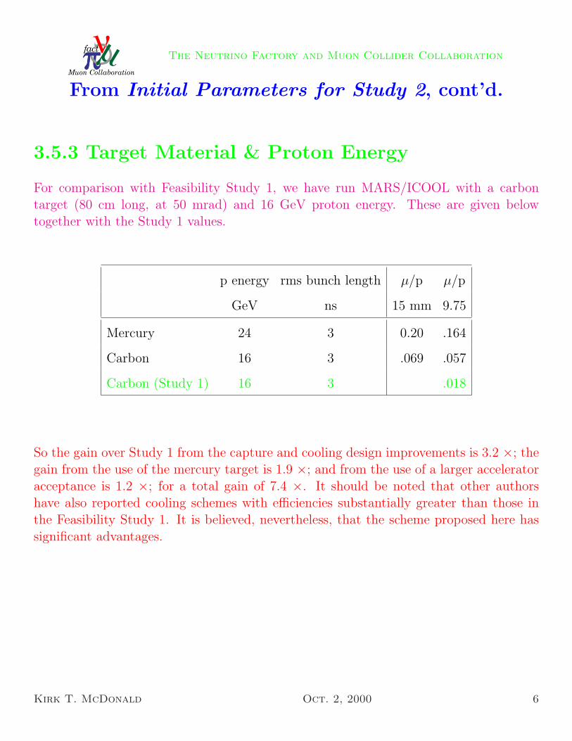
For comparison with Feasibility Study 1, we have run MARS/ICOOL with a carbontarget (80 cm long, at 50 mrad) and 16 GeV proton energy. These are given belowtogether with the Study 1 values.
p energy rms bunch length µ/p µ/p
GeV ns 15 mm 9.75
Mercury 24 3 0.20 .164
Carbon 16 3 .069 .057
Carbon (Study 1) 16 3 .018
So the gain over Study 1 from the capture and cooling design improvements is 3.2 ×; thegain from the use of the mercury target is 1.9 ×; and from the use of a larger acceleratoracceptance is 1.2 ×; for a total gain of 7.4 ×. It should be noted that other authorshave also reported cooling schemes with efficiencies substantially greater than those inthe Feasibility Study 1. It is believed, nevertheless, that the scheme proposed here hassignificant advantages.
Kirk T. McDonald Oct. 2, 2000 6
The Neutrino Factory and Muon Collider Collaboration
Engineering and Simulation Tasks
Four Topics:
1. The target itself.
• Baseline design: Study 2 Parameters document
• Critical issue: Will the first of 6 beam pulses disrupt the
whole mercury jet?
• Engineering: ORNL (?)
• Simulation:
– Pion production: H. Kirk, N. Mokhov
– Thermal hydraulics of beam-jet interaction:
R. Samulyak, N. Simos
– Magnetohydrodynamics of beam-magnet interaction:
S. Kahn, R. Samulyak
Kirk T. McDonald Oct. 2, 2000 7

The Neutrino Factory and Muon Collider Collaboration
The center of the proton beam enters the mercury jet at the
upstream end of the nominal 30 cm long interaction region:
������������ �� ���� ���������� �� ����� �"!$#�%&���'#����(*)�+�,.- �0/1�2)�3*���0/14��5���6%78� �9);:<,�,*���2�<=
>�? @�ACB�>EDF@CGH@�AJICDF@LKMKN? A9OQP�@SR$A�KHGNDFTSU�VXW�Y ULA9TZ@L[*GMU9DFO�T\G
%Z���'#����"%7�� � :5+�+ :<,�, ].^
_a` :Eb�,�c.de:Ebf:5+.gh:Ebi,�c�:_kj :Ebf:<,�]l:Ebf:53k:m:Ebn:�:5^
Kirk T. McDonald Oct. 2, 2000 8

The Neutrino Factory and Muon Collider Collaboration
Thermal Hydraulics
R. Samulyak, using the FRONTIER code:
Beam + Hg jet (no magnetic field), t = 0:
Beam + Hg jet (no magnetic field), t = 6 µs:
Magnetohydrodynamics being added to the code.
Kirk T. McDonald Oct. 2, 2000 9

The Neutrino Factory and Muon Collider Collaboration
The Shape of a Liquid Metal Jet under a Non-uniform Magnetic Field
S. Oshima et al., JSME Int. J. 30, 437 (1987).
Kirk T. McDonald Oct. 2, 2000 10

The Neutrino Factory and Muon Collider Collaboration
How Snapping Shrimp Snap: Through Cavitating BubblesM. Versluis , Science 289, 2114 (2000).
Kirk T. McDonald Oct. 2, 2000 11
The Neutrino Factory and Muon Collider Collaboration
Engineering and Simulation Tasks, cont’d.
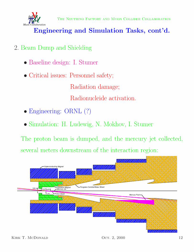
2. Beam Dump and Shielding
• Baseline design: I. Stumer
• Critical issues: Personnel safety;
Radiation damage;
Radionucleide activation.
• Engineering: ORNL (?)
• Simulation: H. Ludewig, N. Mokhov, I. Stumer
The proton beam is dumped, and the mercury jet collected,
several meters downstream of the interaction region:
Kirk T. McDonald Oct. 2, 2000 12
The Neutrino Factory and Muon Collider Collaboration
Engineering and Simulation Tasks, cont’d.
3. Mercury Handling
• Baseline design: SNS (ORNL) [+ ISOLDE (CERN)]
• Critical issues: 25 Atmosphere mercury loop;
Radioactive byproducts
• Engineering: ORNL (?)
• Simulation: H. Ludewig, P. Spampinato
Kirk T. McDonald Oct. 2, 2000 13

The Neutrino Factory and Muon Collider Collaboration
Mercury Handling at the SNS5-16
Shroud
Target Vessel Drain
Cell Floor
FCS
Retract Drive
Separator Tank (2 cu. meter)
Pump
He Supply (From
High Bay)
Pump
Leak Detection
Control & Power System
Target Control System
Pump
Heat
Exchanger
Purification Loop
Activated DeIon. Water Holding
TankLiquid Waste System
Tower Cooling Water
Off-gas
Mercury Target
Target Shielding
Target Plug (100+ tons)
FCS FCS
Water Make-up
Helium Supply
Off-gas
Fig. 5.3-1. Target system diagram.
Target Cell
Plug Assemblies
Utiltiy Vault
Target Cart
Mercury Processing System
Cell Access Hatch
Cell Crane
Target Plug
Fig. 5.3-2. Target system configuration.
Kirk T. McDonald Oct. 2, 2000 14

The Neutrino Factory and Muon Collider Collaboration
Engineering and Simulation Tasks, cont’d.
4. Capture Solenoid
• Baseline design: Study 2 Parameters document
• Critical issue: Hollow conductor vs. Bitter coils in resistive
magnet
• Engineering: NHMFL, B. Weggel
• Simulation: Y. Eyssa, B. Weggel
Kirk T. McDonald Oct. 2, 2000 15