neuron-based vlsi architecture for real-time camera...
TRANSCRIPT

Scientia Iranica B (2015) 22(6), 2150{2162
Sharif University of TechnologyScientia Iranica
Transactions B: Mechanical Engineeringwww.scientiairanica.com
Neuron-based VLSI architecture for real-time cameradistortion correction
C.-H. Chen� and T.-K. Yao
Department of Computer Science and Information Engineering, National Central University, Taoyuan, Taiwan (R.O.C).
Received 22 May 2014; accepted 17 August 2015
KEYWORDSDistortion correction;Neural network;Wide-angle view;VLSI.
Abstract. This paper proposes the e�cient VLSI architecture of camera distortioncorrection, based on a Neural Camera Distortion Model (NCDM). Conventional imagingmethods use over two kinds of models to correct the camera and lens distortions, butthe NCDM uses a single model to immediately correct the geometry distortion andunsymmetrical manufacturing errors. The NCDM, with four neurons, performs a wide-angle distortion correction. The results show that the maximal corrected error in a wholeimage is less than 1.1705 pixels, and the MSE approaches 0.1743 between corrected and idealresults. The distortion correction by NCDM is 429� more accurate than the conventionalapproach. The chip size of NCDM is 1:51 � 1:51 mm2 and contains 126 K gates usingthe TSMC 90 nm CMOS technology process. Working at 240 Mhz, this architecturecan correct 30 frames and a Full-HD resolution video per second. Results show that themaximal corrected error in a whole image is less than 1.4 pixels, and the mean square errorapproaches 0.0376 between corrected and ideal results.© 2015 Sharif University of Technology. All rights reserved.
1. Introduction
A low-price camera has many kinds of manufacturing aws that exist in the lens groups, the holder and thesensor board. To correct the lower quality cameras,Brown et al. [1] presented a lens distortion model thatincludes the decentering lens distortion concept. Then,Wing et al. [2] explained decentering and thin prismdistortions in the camera. He mathematically modeledthese errors and used a calibration board to obtainthe distortion pattern that is used to calculate theparameters of the lens distortion model. They usevarious di�erent mathematical models implementedby software to, respectively, correct camera distor-tions.
For correcting wide-angle lens distortion in realtime, Ansari et al. [3] presented a similar distor-
*. Corresponding author. Tel.: +886-3-422-7151#35211;Fax: +886-3-422-2681E-mail address: [email protected] (C.-H. Chen)
tion polynomial model based on a Nonlinear LeastSquares Curve Fitting (NLSCF) scheme to obtain thecoe�cients of the distortion polynomial. Di�erentto the wide-angle lens distortion model of Wing etal. [2], Ansari�s polynomial model is easier for im-plementing VLSI architecture. So, most recent stud-ies [4-8] have presented hardware accelerator designsbased on Ansari�s method. However, the low-pricecamera still has others distortions that cannot becorrected by VLSI architecture, which means thatfor medical [9] or measuring purposes, the wide-anglecamera cannot correct higher resolution video in realtime.
This study proposes the e�cient VLSI architec-ture of a camera distortion correction method using aNeural Camera Distortion Model (NCDM) to rapidlycorrect various lenses and manufacturing aws of low-price cameras. The NCDM consists of an o�-linecalibration, a Multilayer Feed-Forward Neural Network(MFFNN) [10], and bi-linear interpolation. Becausethe calibration of NCDM is an o�-line preprocess, it is

C.-H. Chen and T.-K. Yao/Scientia Iranica, Transactions B: Mechanical Engineering 22 (2015) 2150{2162 2151
better that the calibration is implemented by software.In the correction process of NCDM, the MFFNN backmaps Distortion Image Space (DIS) coordinates fromCorrection Image Space (CIS) coordinates. The bi-linear interpolation resamples the image pixel if theback mapping DIS coordinates are located in themiddle of two pixels.
The MFFNN uses parallel neuron calculatingto e�ectively solve a variety of nonlinear problemsfor function �tting, data classi�cation, and patternrecognition. The multilayer structure of the MFFNNcan increase the nonlinear modeling capability, butthe complex arithmetic of the network needs morecalculating time, which limits MFFNN application inreal time. To accelerate operation of the MFFNN byhardware, the active function of the neurons using thetan-sigmoid is a bottleneck for implementation, whichis the exponential and dividing arithmetic.
The hardware arithmetic of the tan-sigmoid func-tion can be implemented using analog [11,12] or digitalcircuits. The analog circuit can use a few CMOSgates to generate the analog signal to approximate thetan-sigmoid function. However, the tan-sigmoid usesa digital logic circuit to implement, and has severaladvantages, including better repeatability, exibility,compatibility, testability, and anti-noise. Hence, forimplementing the hardware arithmetic of the MFFNN,many researchers based their studies on digital im-plementations and have proposed various design ap-proaches for the tan-sigmoid, and applications to ob-tain the optimum for nonlinear problems. To designhardware arithmetic that can generate an accurate tan-sigmoid function is a critical route in implementing aneural network.
Recently, implementation of a hardware accel-erator for the tan-sigmoid can be classed by fourmethods; the look-up table, approximation, the Taylorseries, and the coordinate rotation digital computer(CORDIC).
(i) Look-up table: For application in an industrialcontroller, Orlowska-Kowalska et al. [13] used asoftware program to automatically generate theLUT of the activation function of the NN forField-Programmable Gate Array (FPGA) imple-mentation. However, to generate a more accurateactivation function, the LUT needs more memoryspace to memorize the sample points on the curveof the activation function. Then, Himavathi [14]analyzed the activation function, and found thebest size of LUT was in the neural network (NN).Increasing the accuracy of the LUT output willincrease memory size exponentially. Generally,the LUT approach is suitable for applications thatdo not require higher accuracy.
(ii) Approximation: Savich et al. [15] and
Hariprasath and Prabakar [16] use several simplelinear functions to �t the tan-sigmoid, which usethe lowest resources to implement tan-sigmoidarithmetic without memory. Using a linear func-tion makes the approximation approach di�cultfor increasing the precision of the result. The ap-proximation approach is suitable for applicationswith lower accuracy than the LUT methods.
(iii) Taylor series: Zhou et al. [17] used a 7 orderTaylor series and a Look-Up-Table (LUT) to gen-erate the exponential function, which is operatedin the oating point number. In this method,if the orders of the Taylor series are enough,the exponential arithmetic can generate accurateresults, as well as the software program. However,the Taylor series approach uses many resources toimplement the factorial arithmetic.
(iV) CORDIC: Zhu and Chen [18] used a CORDICapproach to implement the exponential arith-metic, which generates more accurate results thanTaylor series methods with the same resources.CORDIC uses addition and subtraction to gainexponential results. Its arithmetic is simpleand regular, and it is suitable for implement-ing hardware with Very-Large-Scale Integration(VLSI) technology. Zhu's approach operates theexponential function between 0 and 10, whichapplies to the probabilistic neural network. Inthis study, the tan-sigmoid of the MFFNN op-erates the exponential arithmetic from -16 to16. For this requirement, this study analyzes theoutput characteristics of the CORDIC arithmetic,and proposes a modi�ed design of the CORDICarithmetic for generating higher accuracy resultsof the exponential.
2. Neural camera distortion model
The Back Propagation Neural Network (BPNN) [19]consists of the feed-forward stage, which is the Multi-layer Feed-Forward Neural Network (MFFNN), and theerror back-propagation stage. Because most problemsin the real world are nonlinear, the MFFNN uses amultilayered structure to enhance the adjustability ofthe nonlinear output results. The MFFNN learns fromthe supervised learning method, which is an ErrorBack-Propagation (EBP) method for error correctionlearning. The neuron bias modi�cation method issimilar to that of the neuron weight. In the trainingepoch, all the training patterns use a feed-forwardoperation to calculate the results. Then, the back-propagation operation estimates the errors betweenthe results and the target patterns. According to theerrors, the weights and biases of the neural networkare modi�ed. The BPNN continues using the training

2152 C.-H. Chen and T.-K. Yao/Scientia Iranica, Transactions B: Mechanical Engineering 22 (2015) 2150{2162
Figure 1. Calibration image of 120� wide-angle lens.
epoch of the EBP method to train until the stoppingcondition is met. Upon completing the EBP methodtraining, the BPNN stops back-propagation and onlyuses feed-forward to back map the camera distortionsurface.
NCDM models various lens distortions with aMFFNN, which can simplify the correction processingof lens distortions. The various mathematical models oflens distortion are integrated into one model. However,if the MFFNN directly models the 3-D distortion curvesurface, computations of the MFFNN that have morethan three-layers or too many neurons in the hiddenlayer are very complex and slow. Researchers donot popularly use the neural network to model lensdistortion.
This study uses a 105� and a 120� wide-angle lensto build the NCDM. Distortion of a low-price 120�wide-angle lens consists of many convex and concavelenses, and the optical characteristics of this wide-anglelens are more complex. Figure 1 shows a calibrationimage that uses a 1920� 1080 pixels resolution camerawith a 120� wide-angle lens to capture the calibrationboard. Because of distortion, the distance betweenadjacent dots is di�erent between the most peripheraland the center area of the Detected Calibration Dots(DCD), which has little distortion. The averagedistance is estimated using the nine adjacent dots in thecenter, and the Virtual Calibration Dots (VCD) use theaverage distance to build the grid dots. The built griddots have the same distance between the neighboringdots.
Figure 2(a) shows the VCD and the DCD of a1280� 1024 resolution camera with a 105� wide-anglelens, which uses the estimated center from the DCD toalign with each other in the image space. Figure 2(b)shows the VCD and DCD of a 1920 � 1080 resolutioncamera with a 120� wide-angle lens.
Figure 2(c) shows the distortion depth of a 105�wide-angle lens that estimates the di�erence betweenthe DCD and the VCD, and the maximum distortionis more than 150 pixels in the most peripheral region.Figure 2(d) shows that the maximum distortion of the120� wide-angle lens is more than 100 pixels in themost peripheral region. From the distortion surface,
the quality of the 105� wide-angle lens is better thanthat of the 120�lens.
To reduce the network size of the MFFNN, thetraining pattern of the MFFNN is very important. Forgenerating the training pattern, the VCD is sequen-tially inputted into the input neurons of the MFFNN.According to the calculated errors of the output resultsbetween the results of the MFFNN and the DCD, theEPB training method modi�es the weights and biasesof the MFFNN.
In this paper, we propose a method that reducesthe complexity of the MFFNN using a method toreduce the complex 3-D distortion surface. The bestoperating range of the MFFNN is the region thatincludes positive and negative oating numbers, andbetween 1 and -1. Generally, researchers use thelens center to calculate the radial distortion vectors.However, in low-price cameras, the lens center is nota known parameter, and it is very hard to estimatethe right location coordinates. Di�erentiating betweenthe lens center and the point of the DIS is not agood training pattern because it is too big for a simpleMFFNN.
Hence, the NCDM uses the di�erence between thepoints of the DIS and the CIS to train the MFFNN,which is given by:�
dxdy
�=�xdyd
���xcyc
�; (1)
where�xd yd
�T is the point in the DIS, and�xc yc
�T isthe corresponding point in the CIS. The curved surfacein Figure 3(a) is the x-axis direction di�erentiation ofthe surface in Figure 2 between the distortion of the x-axis coordinates and their correction. In Figure 3(b),the curved surface of dy, which is the di�erence betweenthe distortion and correction of y-axis coordinates, issimilar to the curved surface of Figure 3(a). Hence,the curved surface of Figure 2 decomposes into twodi�erent directions of the curved surface.
After reducing the distortion surface, the neuralbased back mapping uses an e�cient NCDM to modelthe di�erentiation of the x- and y-directions. InFigure 4, besides the input and output layer, thestructure of the NCDM has a single hidden layer, whichis a single hidden layer MFFNN. In the hidden layer,the neurons use the tan-sigmoid function to normalizethe output range of the hidden neuron. The neuron inthe output layer gathers the results of the hidden layer,and are, respectively, multiplied by the weight of theoutput layer. Then, the neuron outputs sum up all themultiplied results, which is a distortion di�erentiationof the camera distortion surface.
The NCDM uses 4 neurons to model the distor-tion surfaces of Figure 5. After the BP training, thecorrection error of a 105� wide-angle lens in Figure 5(a)

C.-H. Chen and T.-K. Yao/Scientia Iranica, Transactions B: Mechanical Engineering 22 (2015) 2150{2162 2153
Figure 2. Virtual calibration and distortion surface: (a) Calibration dots pattern for 1280 � 1024 resolution camera with105� lens; (b) calibration dots pattern for 1920� 1080 resolution camera with 120� lens; (c) distortion surface for 105�lens; and (d) distortion surface for 120� lens.
Figure 3. Di�erential result of distortion surface for (a) x-axis and (b) y-axis.
Figure 4. Neural camera distortion model.
is under 1.6 pixels. Figure 5(b) shows the maximumcorrection error of a 120� wide-angle lens in thesurround arrives at 1.4 pixels.
In Figure 6, the trained NCDM with 4 neuronsis used to correct the distortion image, and the humaneye is unable to observe distortion in the surround.
3. VLSI architecture of neural processor
3.1. Arithmetic circuit designFigure 7 is the arithmetic circuit of a neural processorfor the NCDM that consists of 2-input hidden neuronsand 4-input output neurons. Because the input dataof the correction neural network are 2-D coordinates(x; y), the hidden layer in the MFFNN consists offour 2-input neurons. To operate the 2-input neuronsat higher operating frequency, the hidden neuron isdesigned using pipeline architecture. After the inputvalue is multiplied by the weight, the pipe registersstore the multiplied results. Then, the summed resultof the multiplied results, and the bias store in the nextstage pipe register is the net signal. The MFFNN inthis study uses the register to store the descriptor of

2154 C.-H. Chen and T.-K. Yao/Scientia Iranica, Transactions B: Mechanical Engineering 22 (2015) 2150{2162
Figure 5. Training error of (a) 105� and (b) 120� wide-angle lens with 4 neurons.
Figure 6. Corrected image of 120� wide-angle lens with 4neurons.
the neural network that controls the weights and biasesof the hidden neurons in the neural network. In thememory mapping of the bus system, the bus interfaceoperates the descriptor register to write a value toregister, or to read a value by the microprocessor.
The arithmetic structure of the output neuron issimilar to the 2-input neuron. The pipe register storesthe multiplied results of aHN
0�3 and wON0�3. Every two
multiplied results in the pipe register use an adderto sum, and the summed results store in the secondstage pipe register. Then, the third stage pipe registerpreserves the summed result that sums up the summed
results of the second stage and the bias. To makeit simple to connect the neuron at the next stage,the input value of the neuron is limited to a rangebetween 1 and -1. Thus, the neurons can constituteany structure of the neural network for any purposes.
When the wide-angle lens is changed to others,the neural network can use the same neuron to correctthe distortion. The input pixel coordinates of othercameras only need to normalize to a range between 1and -1. The neural network uses new normalized datato train the weights and biases for a new camera. Thenormalized design of the neuron is a re-use structure.For di�erent applications, the neural network onlyredesigns the normalization arithmetic.
The arithmetic operation in the neuron uses the�xed point to calculate. The input and output widthsof the neuron in the neural network for camera correc-tion are 24 bits. The normalized value can completelyutilize the 24-bit width of the multiplier and the adderin the neuron, which can output most calculations withprecision. By controlling the weights and biases to a�xed point value within a 24-bit width, the limitedrange can ensure that the multiplied and summedoperations in the neuron do not over ow. Then, theoutput range of the neuron is limited to a �xed range,
Figure 7. Arithmetic circuit of neural processor.

C.-H. Chen and T.-K. Yao/Scientia Iranica, Transactions B: Mechanical Engineering 22 (2015) 2150{2162 2155
which simpli�es the e�ective operating range of the tan-sigmoid arithmetic.
3.2. Tan-sigmoid accelerationThe tan-sigmoid function:
f(n)tansig =2
1 + e� n � 1; (2)
is the most critical function in the neural network forVLSI implementation, which consists of an exponentialand a divider. According to the review in Section 1,implementation of the tan-sigmoid function has fourtypes:
(i) The operating range of the tan-sigmoid is dividedinto several regions, and the relation between theinput value and corresponding output are storedin a look-up table. If the applications do notneed higher output precision, the look-up tableis a rapid approach;
(ii) The operating range of the tan-sigmoid is alsodivided into several regions, and every regionof the tan-sigmoid uses an approximate linearpolynomial to �t the output result. This approachcan provide a more similar output precision, andis a lower cost implementation than the look-uptable;
(iii) The above approaches do not appropriately usethe same application and need higher precision.To accurately correct camera distortion, we pro-pose a method to improve the output character-istics of CORDIC arithmetic.
It is di�cult for the exponential function of the tan-sigmoid to generate the exponential function usinghardware arithmetic. In this study, a coordinate rota-tion digital computer (CORDIC) is used to implementthe hardware arithmetic of the exponential function.However, CORDIC cannot directly generate the valueof the exponential, which is operated in rotationalmode to generate the results of the cosh(�) and sinh(�).In Eq. (3), the exponential value of � is the summedresult of cosh(�) and sinh(�):
e� = cosh(�) + sinh(�): (3)
Eq. (4) is the iterative function of CORDIC basedon a pseudo-rotation method. To generate the valuesof cosh(�) and sinh(�), the CORDIC is operated inrotational mode to calculate the hyperbolic function:8>><>>:
xk+1 = xk �m�kyk2�k
yk+1 = yk + �kxk2�k
zk+1 = zk � �k"k(4)
where m = �1 for the hyperbolic function. In therotational mode, �k in Eq. (5) uses the sign of zk+1
to decide if the next iteration is positive or negativerotation:
�k =
(�1; if zk < 0
1; otherwise.(5)
where k > 0. In (6), "k is the rotating angle at the kstage:
"k = tanh�1(2�k); (6)
where k > 0. After several iterative operations, zk+1almost closes to 0. xk+1 and yk+1 converge in ahyperbolic term that can be written as:(
xk+1 = Kh(x0 cosh(z0) + y0 sinh(z0)
yk+1 = Kh(y0 cosh(z0) + x0 sinh(z0))(7)
where k > 0. Kh is produced from each pseudo-rotation operation, which is given by:
Kh =NYi=0
p1� 2�2i; (8)
where N is de�ned as the times of the pseudo-rotationoperation. Kh is a constant, as N is greater than 25.Figure 8 shows the result of the exponential using theHBCORDIC and standard C/C++ library, and theobvious di�erence is between 0 and 0.04.
Figure 9 is the output error between the HBC andthe standard C/C++ library (STD), which has a twopart obvious di�erence. Between 0 and 0.04, the HBCcannot converge to the objective, which is the resultof the STD. The second di�erence is generated fromthe front of several of the rotation operations. Thesummed angle of the twice rotating operation cannotuse the rotating operation to compensate, which is anover rotating error.
Figure 8. Output characteristics of exponential usinghyperbolic CORDIC.

2156 C.-H. Chen and T.-K. Yao/Scientia Iranica, Transactions B: Mechanical Engineering 22 (2015) 2150{2162
Figure 9. Output error of tan-sigmoid circuit: (a) The subtraction output error; and (b) the logarithm output errorbetween HBC and STD.
Figure 9(b) is the log result of the output error,and the error in most areas is between 10�15 and 10�14.Because the operating range of the tan-sigmoid is from16 to -16, this study proposes a method to modify theHBC, which can improve the error between 0 and 0.04.
The error of the HBC between 0 and 0.04 isgenerated from the rotating operation of HBC notstarting from 0, and thus, the result of the HBC cannotconverge to the objective. In Eq. (9), "k is an unlimitednumber when k is 0. Hence, an added negative rotatingoperation [20] is used to change the starting angle ofthe HBC:
"k = tanh�1(1� 2k�2); (9)
where k = 0. A new negative pseudo-rotation (10) usesthe rotating angle of "0 to modify the error of the HBCbetween 0 and 0.04:8>><>>:
xk+1 = xk �m�kyk(1� 2k�2)
yk+1 = yk + �kxk(1� 2k�2)
zk+1 = zk � �k"k(10)
where k = 0 and m = �1. Because of adding a negativerotation, the scale-factor Kh must also be multiplied bya scaling value for the added negative pseudo-rotation,and is given by:
Kh =q
1� (1� 2(i�2))2NYi=0
p�2�2i: (11)
Figure 10 is the result of the exponential using Modi�edHBC (MHBC) and the STD. Because the MHBC addeda negative pseudo-rotation, the convergence range ofthe MHBC expands to about �2.
Figure 11(a) is the output error of the exponentialbetween the MHBC and the STD. Because of addinga negative pseudo-rotation, the region of the overrotating error in Figure 9(a) between 0.5 and 0.6 movesclose to 0.4 in Figure 11(a). The maximum error inFigure 11(a) is close to �0:12. To amplify the few
Figure 10. Exponential output characteristics usingmodi�ed hyperbolic CORDIC.
errors, for the most part, in Figure 11(a), the resultsuse the logarithm function to calculate their negativeexponent, which is shown in Figure 11(b). Most errorsin Figure 11(a) are less than 10�14, besides the regionat 0:4 � 0:5 and 0:9 � 1:0.
However, the convergence range in Figure 11(a)has a critical section between 0.4 and 0.45.
The neuron in the ANN needs the tan-sigmoid(2) to converge the multiple-accumulated results ofthe weights and biases at a range between 1 and �1.The calculating range of the multiple-accumulate of theneuron is from -15 to 15.
To expand the operating range of the hyperbolicCORDIC, most studies [18,21] based on CORDICdivide the operating range of the EXP into severalregions. Ansari [21] divided the z0 in Eq. (3) intoan integer and fraction, and preprocesses the integerresults of the EXP that is stored in the lookup table.The expanded exp(�z0) is calculated from:
exp(�z0) = exp(�zinteger) � exp(�zfraction); (12)
where �zinteger is the negative integer part of �z0,and �zfraction is the fraction part of �z0, that is

C.-H. Chen and T.-K. Yao/Scientia Iranica, Transactions B: Mechanical Engineering 22 (2015) 2150{2162 2157
Figure 11. (a) The subtraction error, and (b) the logarithm error of the exponential between the MHBC and STD.
Figure 12. Tan-sigmoid output characteristics usingmixed MHBC and STD.
0 � �zfraction < �1. The HBC in the [21] is usedto generate the exp(�zfraction), and the preprocessingexp(�zinteger) multiplied by the result of the HBC isexp(�z0), which e�ectively expands by more than �1.
However, the MHBC generates the error regionsas 0.25. To keep out error regions, the exponential re-writes to:
exp(�z0) =exp(�zinteger) � exp(�zhalf)
� exp(�zquad) � exp(�zfraction): (13)
Figure 12 shows the output characteristics using MixedMHBC (MMHBC), and that the results of the MHBCare very like the result of the standard tan-sigmoid.
Figure 13 shows the output error of the tan-sigmoid between the MMHBC and the standard; this�gure shows that the error is less than 10�5.
Figure 14 shows the MSE results of three di�erentlength �xed points. It shows that as the length ofthe �xed point is more than 20-bit, the increased ratioof the MSE is less than the �xed point using 20-bit.
Figure 13. Output error using MMHBC.
Figure 14. MSE of the tan-sigmoid using three di�erentwidths of �xed point implementation.
According to this result, the tan-sigmoid of this studyuses a 20-bit �xed point to implement.
In Eq. (2), after calculating the exponential, theresult must be inversed. However, if using a divider toinverse the exponential result, the hardware arithmetic
2158 C.-H. Chen and T.-K. Yao/Scientia Iranica, Transactions B: Mechanical Engineering 22 (2015) 2150{2162
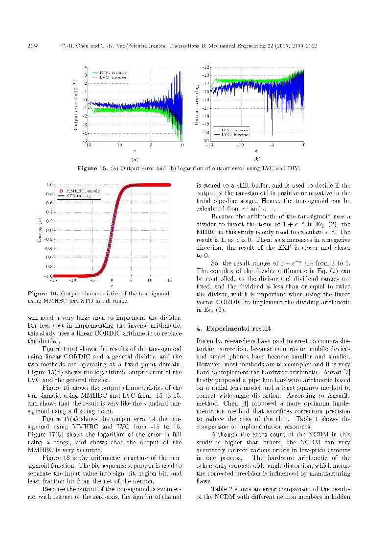
Figure 15. (a) Output error and (b) logarithm of output error using LVC and DIV.
Figure 16. Output characteristics of the tan-sigmoidusing MMHBC and STD in full range.
will need a very large area to implement the divider.For less cost in implementing the inverse arithmetic,this study uses a linear CORDIC arithmetic to replacethe divider.
Figure 15(a) shows the results of the tan-sigmoidusing linear CORDIC and a general divider, and thetwo methods are operating at a �xed point domain.Figure 15(b) shows the logarithmic output error of theLVC and the general divider.
Figure 16 shows the output characteristics of thetan-sigmoid using MMHBC and LVC from -15 to 15,and shows that the result is very like the standard tan-sigmoid using a oating point.
Figure 17(a) shows the output error of the tan-sigmoid using MMHBC and LVC from -15 to 15.Figure 17(b) shows the logarithm of the error in fullusing a range, and shows that the output of theMMHBC is very accurate.
Figure 18 is the arithmetic structure of the tan-sigmoid function. The bit-sequence separator is used toseparate the input value into sign bit, region bit, andleast fraction bit from the net of the neuron.
Because the output of the tan-sigmoid is symmet-ric, with respect to the zero-axis, the sign bit of the net
is stored to a shift bu�er, and is used to decide if theoutput of the tan-sigmoid is positive or negative in the�nial pipe-line stage. Hence, the tan-sigmoid can becalculated from ez and e�z.
Because the arithmetic of the tan-sigmoid uses adivider to invert the term of 1 + e�z in Eq. (2), theMHBC in this study is only used to calculate e�z. Theresult is 1, as z is 0. Then, as z increases in a negativedirection, the result of the EXP is closer and closerto 0.
So, the result ranges of 1 + e�z are from 2 to 1.The complex of the divider arithmetic in Eq. (2) canbe controlled, as the divisor and dividend ranges are�xed, and the dividend is less than or equal to twicethe divisor, which is important when using the linearvector CORDIC to implement the dividing arithmeticin Eq. (2).
4. Experimental result
Recently, researchers have paid interest to camera dis-tortion correction, because cameras on mobile devicesand smart phones have become smaller and smaller.However, most methods are too complex and it is veryhard to implement the hardware arithmetic. Ansari [7]�rstly proposed a pipe-line hardware arithmetic basedon a radial lens model and a least squares method tocorrect wide-angle distortion. According to Ansari�smethod, Chen [4] proposed a more optimum imple-mentation method that sacri�ces correction precisionto reduce the area of the chip. Table 1 shows thecomparison of implementation resources.
Although the gates count of the NCDM in thisstudy is higher than others, the NCDM can veryaccurately correct various errors in low-price camerasin one process. The hardware arithmetic of theothers only corrects wide-angle distortion, which meansthe corrected precision is in uenced by manufacturing aws.
Table 2 shows an error comparison of the resultsof the NCDM with di�erent neuron numbers in hidden

C.-H. Chen and T.-K. Yao/Scientia Iranica, Transactions B: Mechanical Engineering 22 (2015) 2150{2162 2159
Figure 17. (a) Output error and (b) logarithm of the tan-sigmoid using MMHBC in full range.
Figure 18. The tan-sigmoid arithmetic using MHBRC.
Table 1. VLSI implementations comparison.
[7] This work [7] [4] This Work
FPGA/ASIC process Altera ApexEP20K600EBC652
Altera CycloneV 5CEFA7F31C8
0.18 �m 0.18 �m TSMC 90 nm
Logic elements 18,344 20,218 - - -
Gates - - 44,992 28,662 263,080
Frequency 40 Mhz 98.63 200 200 300
Throughput 30 Mpixels/s 98.63 30 160 300
Table 2. Correction precision error comparison with di�erent degree wide-angle lens.
PBM Order (N) Lens MSE Min. error Avg. error Max. error
6 105� 87.9597 0.1038 7.8584 21.1068
7 87.9452 0.0389 7.8571 20.9047
8 87.9316 0.0308 7.8566 20.8914
NCDM Neurons (HN)
4 105� 0.205017 0.000726 0.252331 4.621188
5 0.021510 0.001243 0.104972 0.573920
6 0.005172 0.000013 0.047855 0.357827
4 120� 0.037571 0.000074 0.122573 1.402213
5 0.007127 0.000023 0.056211 0.435714
6 0.004582 0.000368 0.044143 0.353196
This work Neurons (HN)
4 120� 0.150788 0.009167 0.336822 1.170525

2160 C.-H. Chen and T.-K. Yao/Scientia Iranica, Transactions B: Mechanical Engineering 22 (2015) 2150{2162
layers, and the PBM with di�erent polynomial order.In software using a oating point with a 120� wide-angle, the results show that MSE achieves 0.037571,as the number of the neurons in NCDM is 4, and themaximum error is 1.40221260 pixels. When the numberof the neurons is 7, the maximum error in the wholeimage is under 0.32898513 pixels. However, in thiscamera sensor, the pixel width is 2.8 �m. If the numberof neurons is greater than 4, the di�erence in thecorrected image cannot be observed by the human eye.So, the optimum neuron number is 4 for the 120-degreewide-angle lens and the 1920�1080 resolution camera.Although the chip area of the NCDM is 10 times biggerthan that in Ansari�s work [7], the NCDM is 429 timesmore accurate than the 6 order PBM that is based onAnsari�s method with the 105� wide-angle lenses.
Because the hardware arithmetic uses a �xedpoint with 120� wide-angle lenses, part of the correc-tion errors are from the transformation errors of the oating point coordinates. The operating range of theNCDM using a oating point is -1�1. However, toe�ciently utilize the pipe-line register width of VLSIarchitecture, the range of the NCDM using a �xedpoint is �0:9999 � 0:9999. The result shows thatMSE still achieves 0.150788011 as the NCDM hardwarearithmetic with 4 neurons, and the maximum error is1.170525455 pixels.
Figure 19 shows the precision errors of the neuralprocessor, which are di�erent errors of the wholeimage between post-simulation and ideal results. Thehardware arithmetic of the neural processor uses a�xed point to implement, and the ideal software isimplemented by a oating point numeric domain.Results show that most errors are lower than 10�6,and some errors are greater than 10�5 in the wholedistortion image. Because the NCDM back maps toa distortion curve surface, the very small di�erenceerrors in the curve critical region cause the result ofthe software to map to the next curve, and the resultof the hardware maps to the current curve, which
Figure 19. Neurons map on tape-out chip.
Figure 20. Captured distortion image from 1920� 1080resolution camera with 120�.
Figure 21. Corrected image obtained by the proposedneural correction chip.
generate the protruding points at every �xed distance.Following the reason, the MSE of the VLSI NCDMarchitecture is more than the NCDM using a oatingpoint. As the case stands, the protruding points arenot wrong events, because the CIS coordinates usedfor back mapping have transformation errors betweenthe oating point and the �xed point.
Figure 20 shows a distortion image captured froma 1920 � 1080 resolution camera with a 120� wide-angle lens in which one can observe the clear wide-angledistortion.
Figure 21 is the corrected image of Figure 20,which shows the distortion region has corrected by theNCDM.
The chip size of NCDM is 1:51 � 1:51 mm2,containing 126 K gates using the TSMC 90 nm CMOStechnology process. Figure 22 shows a neuron map dia-gram illustrating the place and routing location of theRead Only Memory (ROM), the hidden neurons andoutput neurons. The ROM is used to store the powerregion of the exponential, which selects the shift timesof the exponential arithmetic output. The utilizationrate of the area surrounded by the pad is 79.22%.
5. Conclusion
In this paper, we design and implement an e�cientVLSI architecture of a camera distortion correction

C.-H. Chen and T.-K. Yao/Scientia Iranica, Transactions B: Mechanical Engineering 22 (2015) 2150{2162 2161
Figure 22. Neurons map on tape-out chip.
method based on the NCDM (Neural Camera Distor-tion Model). It can rapidly and accurately correctvarious lenses and the manufacturing aws of low-price cameras. In the o�-line calibration processing,the NCDM only captures a single calibration imageto calculate the distortion vector, and does not needto estimate the optical center. The NCDM with fourneurons performs the wide-angle distortion correction.Results show that the maximal corrected error in awhole image is less than 1.1705 pixels, and the MSEapproaches 0.1743 between the corrected and idealresults. The distortion correction by NCDM is 429times more accurate than the conventional approach.The implementation of a NCDM chip use a TSMC90 nm CMOS technology process. The chip size is1:51� 1:51 mm2 and contains 126 K gates. While thechip works at 240 Mhz, the NCDM can correct over 30frames in a full HD resolution video per second, whichmeets real-time distortion corrections for streamingvideo applications.
References
1. Brown, D.C. \Close-range camera calibration", Pho-togramm. Eng. Remote Sens., 8(37), pp. 855-866(1971).
2. Wing, J., Cohen, P. and Herniou, M. \Camera cal-ibration with distortion models and accuracy eval-uation", Pattern Analysis and Machine Intelligence,IEEE Transactions on, 14(10), pp. 965-980 (1992).
3. Ansari, K.V., Kumar, S. and Radhakrishnan, D. \Anew approach for nonlinear distortion correction inendoscopic images based on least squares estimation",IEEE Transactions on Medical Imaging, 18(4), pp.345-354 (1999).
4. Chen, S.-L., Huang, H.-Y. and Luo, C.-H. \Time mul-tiplexed VLSI architecture for real-time barrel distor-tion correction in video-endoscopic images", Circuitsand Systems for Video Technology, IEEE Transactionson, 21(11), pp. 1612-1621 (2011).
5. Chen, P.Y., Huang, C.C., Shiau, Y.H. and Chen, Y.T.\A VLSI implementation of barrel distortion correc-tion for wide-angle camera images", IEEE Transac-tions on Circuits and Systems Ii-Express Briefs, 56(1),pp. 51-55 (2009)
6. Qiang, L. and Allinson, N.M. \FPGA implementationof pipelined architecture for optical imaging distortioncorrection", in Signal Processing Systems Design andImplementation, 2006. SIPS '06. IEEE Workshop on,Ban�, Canada, pp. 182-187 (2006).
7. Ngo, H.T. and Ansari, V.K. \A pipelined architecturefor real-time correction of barrel distortion in wide-angle camera images", IEEE Transactions on Circuitsand Systems for Video Technology, 15(3), pp. 436-444(2005).
8. Ansari, K.V. \Design of an e�cient VLSI architecturefor non-linear spatial warping of wide-angle cameraimages", Journal of Systems Architecture, 50(12), pp.743-755 (2004).
9. Melo, R., Barreto, J.P. and Falcao, G. \A new solutionfor camera calibration and real-time image distortioncorrection in medical endoscopy initial technical eval-uation", Biomedical Engineering, IEEE Transactionson, 59(3), pp. 634-644 (2012).
10. Hornik, K., Stinchcombe, M. and White, H. \Multi-layer feedforward networks are universal approxima-tors", Neural Netw., 2(5), pp. 359-366 (1989).
11. Choi, J., Bang, S.H. and Sheu, B.J. \A programmableanalog VLSI neural network processor for communica-tion receivers", Neural Networks, IEEE Transactionson, 4(3), pp. 484-495 (1993).
12. Satyanarayana, S., Tsividis, Y.P. and Graf, H.P.\A recon�gurable VLSI neural network", Solid-StateCircuits, IEEE Journal of, 27(1), pp. 67-81 (1992).
13. Orlowska-Kowalska, T. and Kaminski, M. \FPGAimplementation of the multilayer neural network forthe speed estimation of the two-mass drive system",Industrial Informatics, IEEE Transactions on, 7(3),pp. 436-445 (2011).
14. Himavathi, S., Anitha, D. and Muthuramalingam,A. \Feedforward neural network implementation inFPGA using layer multiplexing for e�ective resource

2162 C.-H. Chen and T.-K. Yao/Scientia Iranica, Transactions B: Mechanical Engineering 22 (2015) 2150{2162
utilization", IEEE Trans. Neural Netw., 18(3), pp.880-888 (2007).
15. Savich, A.W., Moussa, M. and Areibi, S. \The impactof arithmetic representation on implementing MLP-BP on FPGAs: A study", Neural Networks, IEEETransactions on, 18(3), pp. 240-252 (2007).
16. Hariprasath, S. and Prabakar, T.N. \FPGA implemen-tation of multilayer feed forward neural network archi-tecture using VHDL", in 2012 International Confer-ence on Computing, Communication and Applications(ICCCA), pp. 1-6 (2012).
17. Zhou, F., Liu, J., Yu, Y., Tian, X., Liu, H., Hao, Y.,et al. \Field-programmable gate array implementationof a probabilistic neural network for motor corticaldecoding in rats", Journal of Neuroscience Methods,185(2), pp. 299-306 (2010).
18. Zhu, X.-P. and Chen, Y.-W. \Improved FPGA imple-mentation of probabilistic neural network for neuraldecoding", in 2010 International Conference on Ap-perceiving Computing and Intelligence Analysis (ICA-CIA), pp. 198-202 (2010).
19. Rumelhart, D.E., Hinton, G.E. and Williams, R.J.\Learning internal representations by error propaga-tion", in Parallel Distributed Processing: Explorationsin the Microstructure of Cognition, 1, MIT Press, Ed.,pp. 318-362 (1986).
20. Hu, X., Harber, R.G. and Bass, S.C. \Expandingthe range of convergence of the CORDIC algorithm",IEEE Transactions on Computers, 40(1), pp. 13-21(1991).
21. Gisutham, B., Srikanthan, T. and Ansari, K.V. \Ahigh speed at CORDIC based neuron with multi-levelactivation function for robust pattern recognition",in Fifth IEEE International Workshop on ComputerArchitectures for Machine Perception, 2000, pp. 87-94(2000).
Biographies
Ching-Han Chen was born in Kinmen, Taiwan, in1963. He received his BS and MS degrees in Geophysicsfrom the National Central University, Taiwan, in 1986and 1988, respectively, a DEA (Diplome d'EtudesApprofondies) in Informatique, Automatique et Pro-ductique, in 1992, and a PhD degree from Franche-Comte University, France, in 1995. He is currentlyAssociate Professor in the Department of ComputerScience and Information Engineering at the NationalCentral University, Taoyuan County, Taiwan. Hisresearch interests include embedded system design,multimedia signal processing, and robotics.
Tun-Kai Yao received a BS degree in ElectricalEngineering from I-Shou University, Taiwan, in 2005,and an MS degree in Electrical Engineering from theNational University of Kaohsiung, Taiwan, in 2007. Heis currently pursuing a PhD degree in the Departmentof Computer Science and Information Engineering atNational Central University, Taiwan. His research in-terests include embedded systems design, VLSI design,image processing, and computer vision.