network supervisor
TRANSCRIPT

http://www.3com.com/
Part No. DUA15100-EAAA03
Published October 2006
3Com® Network Supervisor v5.2User Guide
3C15100E

3Com Corporation350 Campus DriveMarlboroughMA USA 01752-3064
Copyright © 2006, 3Com Technologies. All rights reserved. No part of this documentation may be reproduced in any form or by any means or used to make any derivative work (such as translation, transformation, or adaptation) without written permission from 3Com Technologies.
3Com Technologies reserves the right to revise this documentation and to make changes in content from time to time without obligation on the part of 3Com Technologies to provide notification of such revision or change.
3Com Technologies provides this documentation without warranty, term, or condition of any kind, either implied or expressed, including, but not limited to, the implied warranties, terms or conditions of merchantability, satisfactory quality, and fitness for a particular purpose. 3Com may make improvements or changes in the product(s) and/or the program(s) described in this documentation at any time.
If there is any software on removable media described in this documentation, it is furnished under a license agreement included with the product as a separate document, in the hard copy documentation, or on the removable media in a directory file named LICENSE.TXT or !LICENSE.TXT. If you are unable to locate a copy, please contact 3Com and a copy will be provided to you.
UNITED STATES GOVERNMENT LEGEND
If you are a United States government agency, then this documentation and the software described herein are provided to you subject to the following:
All technical data and computer software are commercial in nature and developed solely at private expense. Software is delivered as “Commercial Computer Software” as defined in DFARS 252.227-7014 (June 1995) or as a “commercial item” as defined in FAR 2.101(a) and as such is provided with only such rights as are provided in 3Com’s standard commercial license for the Software. Technical data is provided with limited rights only as provided in DFAR 252.227-7015 (Nov 1995) or FAR 52.227-14 (June 1987), whichever is applicable. You agree not to remove or deface any portion of any legend provided on any licensed program or documentation contained in, or delivered to you in conjunction with, this User Guide.
Unless otherwise indicated, 3Com registered trademarks are registered in the United States and may or may not be registered in other countries.
3Com and the 3Com logo are registered trademarks of 3Com Corporation. XRN is a trademark of 3Com Corporation
IEEE and 802 are registered trademarks of the Institute of Electrical and Electronics Engineers, Inc.
Intel and Pentium are registered trademarks of Intel Corporation. Microsoft, MS-DOS, Windows, and Windows NT are registered trademarks of Microsoft Corporation. Novell and NetWare are registered trademarks of Novell, Inc. UNIX is a registered trademark in the United States and other countries, licensed exclusively through X/Open Company, Ltd.
Netscape Navigator is a registered trademark of Netscape Communications.
HP OpenView is a registered trademark of Hewlett Packard.
JavaScript is a trademark of Sun Microsystems.
All other company and product names may be trademarks of the respective companies with which they are associated.ENVIRONMENTAL STATEMENT
It is the policy of 3Com Corporation to be environmentally-friendly in all operations. To uphold our policy, we are committed to:
Establishing environmental performance standards that comply with national legislation and regulations.
Conserving energy, materials and natural resources in all operations.
Reducing the waste generated by all operations. Ensuring that all waste conforms to recognized environmental standards. Maximizing the recyclable and reusable content of all products.
Ensuring that all products can be recycled, reused and disposed of safely.
Ensuring that all products are labelled according to recognized environmental standards.
Improving our environmental record on a continual basis.
End of Life Statement3Com processes allow for the recovery, reclamation and safe disposal of all end-of-life electronic components.
Regulated Materials Statement3Com products do not contain any hazardous or ozone-depleting material.
Environmental Statement about the DocumentationThe documentation for this product is printed on paper that comes from sustainable, managed forests; it is fully biodegradable and recyclable, and is completely chlorine-free. The varnish is environmentally-friendly, and the inks are vegetable-based with a low heavy-metal content.

Protected by U.S. patents 6,594,696; 6,633,230; 6,646,656; 6,691,161; 6,691,256; 6,701,327; 6,704,284; 6,704,292; 6,763,001; 6,766,367; 6,771,287; 6,775,243; Patents Pending.
Copyright © 2006 3Com Corporation and its licensors. All Rights Reserved. 3Com is a registered trademark of 3Com Corporation.
Cyberons (TM) For Java v3.5 Copyright 2002 by NETAPHOR SOFTWARE, INC.
This product includes software developed by the Apache Software Foundation (http://www.apache.org/).
PuTTY is copyright 1997-2005 Simon Tatham. Portions copyright Robert de Bath, Joris van Rantwijk, Delian Delchev, Andreas Schultz, Jeroen Massar, Wez Furlong, Nicolas Barry, Justin Bradford, Ben Harris, Malcolm Smith, Markus Kuhn, and CORE SDI S.A. Permission is hereby granted, free of charge, to any person obtaining a copy of this software and associated documentation files (the "Software"), to deal in the Software without restriction, including without limitation the rights to use, copy, modify, merge, publish, distribute, sublicense, and/or sell copies of the Software, and to permit persons to whom the Software is furnished to do so, subject to the following conditions: the above copyright notice and this permission notice shall be included in all copies or substantial portions of the Software.


CONTENTS
ABOUT THIS GUIDE
Conventions 20Feedback about this User Guide 21Related Documentation 21
1 GETTING STARTED
Introduction 23What is 3Com Network Supervisor 23Installation 24Activation 24
Getting Started 26Creating a New Network Map 26
Discovery Type Step 26Specify Subnets Step 26Monitor Core Devices and Links Step 26Community Strings Step 26NBX Voice Network Step 26NBX Call Processors Step 27Summary Step 27
Coexistence with other Network Management Applications 27Upgrading from earlier versions of 3Com Network Supervisor 28
Advanced Package compatibility 29Main Features 29
Main Window 29Network Discovery 29Network Monitoring 30The Event System 30Traffic Prioritization 30Reporting 30Live Update 30

2 PRODUCT ACTIVATION
Introduction 33Key Concepts 34Components 34
About Dialog 34Activate Now dialog 34
Examples 36Activating 3Com Network Supervisor 36
Useful Information and References 36Where can I find the product number for 3Com Network Supervisor? 36Where can I find the serial number for 3Com Network Supervisor? 36
Key Considerations 37What if I lose my Activation Key after registration? 37If I re-install the product after it has been activated, do I need to activate it again? 37If I upgrade to Network Supervisor v5.2 from an earlier, activated version of Network Supervisor, do I need to activate it again? 37Why can’t I log in to the 3Com support web site? 37
3 MAIN WINDOW
Overview 39Key Concepts 40
Map Files 40Components 40
Map 40Tree 40Toolbar 40Status Bar 41Main Menu 41File 41Edit 42View 43Device 45Monitoring 46Alerts/Events 47Tools 47
Help 48File > Exit Menu Option 49View > Show Toolbar Menu Option 49Tools > 3Com Wireless Switch Manager 49Tools > EMS Quarantine Utility 50Tools > Options Menu Option 52
General 53Device Management 54Internet 55Discovery 56
Alerts 57Help > Contents and Index Menu Option 58Help > Launch User Guide 58Help > About 3Com Network Supervisor Menu Option 59
Examples 59Finding the Product Version 59Finding the Serial Number and Activation Key 59
4 DISCOVERING THE NETWORK
Overview 61Key Concepts 62
The Discovery Process — Detecting Devices 62IP Ping 63Device Capability Detection 63SNMP Type Detection 64IP to MAC Resolution 64End Station Type Recognition 64Web Type Recognition 65DNS Name Resolution 65NBX Phone Detection 65Device Sizing 66
The Discovery Process — Determining Topology 67Sizing stage 68Spanning Tree stage 68Remote Poll Stage (broadcast ARP) 68Initial Endstation stage 69Device Resolution Stage 69

Remote Poll Stage (directed pings) 69Outstanding end station stage 70Tree Building Stage 70Clouds — Unknown Topology 70Wireless Clients Clouds 74
The Discovery Process — Rediscovery 74Components 75
Launching a discovery 76The Welcome dialog box 76File > New 77Tools > Network Discovery with nothing selected 77Tools > Network Discovery with a discovered subnet selected 77Tools > Network Discovery with an undiscovered subnet selected 78
The Network Discovery Wizard 79Discovery Type Pane 79Specify Subnets Pane 81Editing subnets in the list 84Removing subnets from the list 84Choosing from a list of known subnets 84Monitor Core Devices and Links Pane 86Community Strings Pane 87NBX Voice Network Pane 88NBX Call Processors Pane 89Summary Pane 90
The Network Discovery Progress Dialog Box 91Network Discovery Summary dialog box 92
The Discovery Report 94Discovery 94Topology 95
The Misconfigurations and Optimizations Report 95The Changes Report 96The Displayed Map 96
Initial Map Creation 96Subsequent Map Updates 97
Examples 97I have four separate subnets - how do I specify them? 97I am using different SNMP community strings for different devices on my network - how do I specify this? 98

Useful Information and References 99Why the discovered map may not exactly reflect the network 99
Some devices haven't appeared 99Some devices are the wrong type 100There are clouds in my map 100
Support for 3Com devices 100Support for third party devices 101
Key Considerations 102Discovery Report Errors and Warnings 102
Discovery Section 102Topology Section 104
5 WORKING WITH THE MAP
Overview 109Key Concepts 110
The Map 110The Tree 112
Components 114Map Structure 114The Grouped Network View 114The Ungrouped Network View 116
Devices 116Device Icons 116Pull-Right Menu for Devices 117Physical Links 118Unvalidated Links 118Physical Link Annotations 118Spanning Tree Protocol Support 119Pull-Right Menu for Physical Links 119Layer-3 Connections 121
Clouds 122Pull-Right Menu for Clouds 123Subnets 123Device Groups 126Tooltips 129Map Item Labels and Address Translation 130
Navigation 137

Panning 137Zoom in 137Zoom out 138Fit to page 138Shortcut Symbols 141Navigating Around the Map Using the Tree 143Trace Path 143Using The Trace Path Wizard 146Finding Items on Your Network 147Using Wildcards to Find Partial Matches 148Searching Within the Search Results 149Using the Find Dialog Box to Select Items for Operations 150Finding Devices 150Finding Links 152Finding NBX Telephony Components 153
Modifying the Map Layout 155Manually Modifying the Map Contents 156Adding Items to the Map 156Linking Items in the Map 158Keeping the Map Up-to-date 159
Saving and Opening Maps 159Printing the Map 162
Examples 163Selecting all of the SuperStack 3 Switch 4400 Devices in the Network 163Viewing all of the Physical Connections for a Router 166Focusing in on a Set of Devices in the Map 168Adding a Link between Map Items from Different Submaps 171Adding a New Device on Your Network Into the Map 173
Useful Information and References 176Graphical Support for Specific Device Types 176
NBX Network Telephony Solution 1763Com Switch 4007 1763Com Wireless Access Points 176Files Associated with Saved Maps 177

6 VIEWING DEVICE DETAILS
Overview 179Key Concepts 180
Items Supported by the Properties Dialog Box 180Components 180
Launching the Properties Dialog Box 180Structure of the Properties Dialog Box 181
The Tabbed Pane 181The Device Tree 183
Properties Dialog Box for a Node 185Properties Dialog Box for a Supported Device 186Supported Device (Stack or Chassis) 187Supported Device (Single Unit) 188Properties Dialog Box for an Unsupported Device 188Properties Dialog Box for an End station 189Properties Dialog Box for a Phone 190Properties Dialog Box for a Subnet 192Properties Dialog Box for a Device Group 192Properties Dialog Box for a Cloud 193Properties Dialog Box for a Link 194
Properties Dialog Box for a Link 195Properties Dialog Box for a Layer-3 Connection 196Properties Dialog Box for a Multiple Selection 197Applying Changes to Devices Using the Properties Dialog Box 199
This section describes how you can apply changes to items with the Properties dialog box. 199Changing the Custom Name 199Setting the IP Address for a Manually Added Device 200Setting the Port Numbers for a Manually Added Link 202
Changing the Community Strings for a Device 203Examples 207Key Considerations 210
Troubleshooting 210
7 MONITORING THE NETWORK
Overview 213Key Concepts 213

Monitor 213Monitoring and Event Generation 214Monitoring State 214
Monitoring State and the Grouped View 216Monitoring Techniques 216
IP Ping Monitoring 217SNMP MIB Data Retrieval 217Service Polling 218SNMP Trap Receipt 218
Monitor-able Items 219Monitoring Non-3Com Devices 219
Link Monitoring 219Components 220
Live Graphs Window 220Poll Rates 221
Live Graphs Tree 221Live Graphs Display 222
Displaying Thresholds 222Live Graphs Toolbar 224
Live Graphs Menu 224More Detail Dialog Box 225
Configuration 227Starting and Stopping Monitoring 227
Disabling and Enabling Individual Monitors 228Controlling Event Generation from Monitors 229Registering 3Com Network Supervisor as an SNMP Trap Destination 229
Examples 230Enabling Monitoring on the Core Devices in the Map 230Disabling Monitoring on the Whole Network 231
Key Considerations 231Text Displayed in Graphs 231Problems Starting Monitoring for a Device or Link 232
8 THE EVENT LOG
Overview 235Key Concepts 235

Events 235Event Types 236Monitor-Based Events 236SNMP Trap-Based Events 2363Com Network Supervisor Internal Events 237
Event Severities 237Information Severity 237Warning Severity 237High Severity Events 237Critical Severity 238Recurring Severity 238Event Severity Colors 238
Event Resolution 238Event Correlation 239Recurring Event Handling 239Event Suppression 240SNMP Trap Filtering 240
Alerts 240Events List Components 241
Launching the Events Window 241Events Main Window 242
Events List 243Events Toolbar 244Events Menu 245Status Bars 247
Working With Events 248Navigating to Event Sources in the Map 248Commenting on Events 248Manually Resolving Events 249Deleting Events 250
Refreshing the Events List 251Exporting the Events List to a CSV Format File 252Printing the Events List 253Find Dialog Box 253Filter Dialog Box 254
Name Filter 255Show only voice related events Filter 256Severity Filter 257

Last number of days Filter 257Resolved Filter 257Deleted Events Filter 258Description Filter 258Comment Filter 258Filter Status Bar 259
More Detail Dialog Box 259Event Tab 260
Event System Configuration 261Disabling and Enabling Events 261
Disabled Events Dialog Box 262Selecting Items 263
Controlling How Events are Logged 264Setting Thresholds for Monitor-Based Events 264
High and Warning Thresholds 265Launching the Threshold Settings Dialog Box 265Threshold Settings Dialog Box 265
Managing Event Ageing 268Ageing Dialog Box 269
Alert System Components 271Alerts System Overview 271Configure Alerts Dialog Box 271
Attaching Alerts to Items 272Configure Global Alerts Dialog Box 273
Enabling Global Alerts 274Configuring Alerts 275Launching Alerts When Events are Resolved 277
Examples 279Viewing the Unresolved Events for a Subnet 279Exporting High Severity Events Generated in the Last Week 279Undeleting an Event 281Receiving Notification When A Server Farm Is Unreachable 284
Key Considerations 288No Events in the Events List 288
Events List Update Was Stopped 288Filter Has Excluded All Events 289

9 CREATING REPORTS
Overviews 291Key Concepts 292
Selection-sensitive 292Feature Reports Types 292Device Report History — Restriction 292Custom Report Types 293Reports History 293Export to CSV 293
Components 293Inventory Report 294Capacity Report 294Topology Report 294Free ports Report 295Reports Dialog Box 295
Generate Report Tab 296History Tab 297
Custom Report Types Dialog Box 299Add/Edit Report Type Wizard 300
Columns Step 300Name and Description Step 304Summary Step 304
Examples 305Assessing Network Expansion Capability 305Ensuring Stacks are Running the Same Agent Version 306
Key Considerations 307Report Information Out-of-Date 307Disk Usage 307Generate Report not Working 308
10 CONFIGURING SINGLE DEVICES
Overview 309Key Concepts 309
Web Management 309Telnet Management 310SSH Management 310Administration Menu 310

Network Jack Configuration Manager 310Properties Dialog Box 311
General 311Addresses 312SNMP 313
Registering Devices for Warranty 314Components 314
Device Warranty Dialog Box 314Device Warranty Wizard 315
Introduction Step 316Contact Details Step 317Partner/Reseller Details Step 317Device Selection Step 319Summary Step 320
Connection to the 3Com Server 321What Data is Sent to the 3Com server 321Reports 322
Device Warranty 322Examples 324
Renaming a Switch 4007 using Telnet 324Disabling a Port on a Switch 4400 using the Web Interface 324Registering 3Com Devices for Warranty 324
Key Considerations 326Troubleshooting 326
The Device Warranty dialog box is not displayed after a Network Discovery 3263Com Network Supervisor lists some devices as unregistered, although you have already registered them on the 3Com website 327
Frequently Asked Questions 327Why are some registered devices missing from the email? 327Why is there no warranty associated with some of the devices in the email? 327
11 PRIORITIZING NETWORK TRAFFIC
Overview 329Key Concepts 330
Classification 330Marking 331

Queuing 333Dropping 335Service Levels 335Configuring the Network for End-to-end Traffic Prioritization 336
Components 337Prioritize Network Traffic Wizard 337
Configuration Type Step 338NBX Step 339Servers Step 341Applications Step 342Application Field Values 343Finish Step and Progress 344
Prioritization Reports 344Agent Upgrades Required for Prioritization report 344Network Prioritization Report 345Prioritization Configuration Report 345
Examples 346Applying an Existing Configuration to New Devices 346Prioritizing NBX Voice Traffic 347Prioritizing Traffic To and From a SAP Server 348Blocking Access to a Streaming Audio Server 350Prioritizing a Video Conferencing Application 351Restricting Access to SNMP 354
Useful Information and References 358User Priority Field 358DiffServ Codepoint Field 359Determining Field Values for Applications 3603Com Network Supervisor Classifier Rules for NBX Phone Traffic 360 3Com Network Supervisor Service Levels 361Configuration Levels for Supported 3Com Devices 361
Key Considerations 363Resource Warnings 363Why Errors Can Occur When Adding a Server 365Potential Hazards When Blocking Traffic To and From Servers 365Servers That Cannot be Selected for Blocking 366Potential Hazards of Blocking Application Traffic 367Potential Hazards of Blocking SNMP, HTTP and Telnet 368

12 NBX SUPPORT
Overview 369Key Concepts 369
How 3Com Network Supervisor Discovers the Phone Network 370How 3Com Network Supervisor Represents the Phone Network Icons 370
NBX Call Processor 371Line Cards 371Analog Terminal Adapter and Analog Terminal Card 371NBX Phones and Attendant Consoles 372NBX Applications 372
How 3Com Network Supervisor Monitors the Phone Network 372Components 373
Discovering the NBX Voice Network 373NBX Voice Network Step 373NBX Call Processors Step 373Add NBX Call Processor/Modify NBX Call Processor 375
Properties dialog box 376Monitoring the Phone Network 377
Monitoring the NBX Call Processor 377Monitoring a Phone 377Monitoring a Line Card 378
Understanding Voice-related 3Com Network Supervisor Events 378Events related to the NBX Call Processor 379Events related to phones 379Events related to other links or devices on the network 379
Examples 379Discovering Several NBX Call Processors Simultaneously 379Receiving an Alert when my Phones Stop Working 380
Useful Information and References 381NBX system 381NBX Call Processor 381NBX NetSet 381
Key Considerations 382Troubleshooting 382
The phones are not shown on the map, although there is a NBX Call Processor 382 The display of end stations in the map has been disabled 382

The wrong username/password was specified for the NBX Call Processor 383There is a problem with the HTTP service for the NBX Call Processor 384The NBX Call Processor stopped responding during the network discovery 384
Frequently Asked Questions 385Why are there a lot of unconnected phones on the map? 385The phone was removed from the network 385The phone cannot be reached 385The network device the phone is connected to has not been discovered 386Why are some phones on the map showing the user name, while others show the extension number? 386How do I change the label of a phone or line card? 387
13 LIVE UPDATE
Overview 389Key Concepts 390
Connection Type 390Service Packs 390Live Update Engine 390
Components 391Live Update Setup Wizard 391
Connection Type Step 391Use Custom Settings Step 392Summary Step 393
Live Update Select File Groups Dialog Box 395Status 396Table of Available Updates 397File Group Details 397
Select File Group - Group Name 398Download Progress 399Changing the Download Settings 400Live Update Activity Report 403
Examples 404Ensuring 3Com Devices are Supported 404Updating the Connection Information 405

Solution 1 — Automatic Configuration using the Live Update Setup Wizard 406Solution 2 — Manual Configuration using the Options Dialog Box 407
Useful Information and References 408Proxy Server 408
Key Considerations 408The Proxy Settings are not Retrieved 408Not Enough Space on the Disk 409
A OBTAINING SUPPORT FOR YOUR 3COM PRODUCTS
Register Your Product to Gain Service Benefits 411Solve Problems Online 411Purchase Extended Warranty and Professional Services 412Access Software Downloads 412Contact Us 412
Telephone Technical Support and Repair 413
B SYSTEM REQUIREMENTS
Operating System 417Web Browser 417Additional Software Required 417Hardware 418
C REPORT EXAMPLES
Overview 419Discovery Report 420
Discovery Report Example 420Discovery Report Example Content 421Misconfigurations and Optimizations Report 423
Spanning Tree Fast Start 423XRN Fabric 423
Configure aggregated links using LACP 423Web Cache Redirection 424Misconfiguration and Optimization Reports 424
Limitations 432

Webcache Redirection and VLANs 432Redirection on the Cache Port (49XX) 432Webcache Software Releases 433Restarting Webcache Traffic Server 433
D ADDING TRAP DECODES
E ADDING MAC ADDRESS VENDOR TRANSLATIONS
F INTEGRATING AN SSH CLIENT
INDEX
3COM END USER SOFTWARE LICENSE AGREEMENT


ABOUT THIS GUIDE
This guide is intended for use by those responsible for installing, setting up and managing a network; consequently, it assumes a working knowledge of networks and network management systems.
If the Release Notes provided with this 3Com Network Supervisor User Guide contain details that differ from the information in this guide, follow the information in the release notes.
Most 3Com user guides are available in Adobe Acrobat Reader Portable Document Format (PDF) or HTML on the 3Com World Wide Web site:
http://www.3com.com/

20 ABOUT THIS GUIDE
Conventions Table 1 and Table 2 list conventions that are used throughout this guide.
Table 1 Notice Icons
Icon Notice Type Description
Information note Information that describes important features or instructions.
Caution Information that alerts you to potential loss of data or potential damage to an application, system, or device.
Warning Information that alerts you to potential personal injury.
Table 2 Text Conventions
Convention DescriptionScreen displays This typeface represents information as it appears on the
screen.Syntax The word “syntax” means that you must
evaluate the syntax provided and then supply the appropriate values for the placeholders that appear in angle brackets. Example:
To change your password, use the following syntax:
system password <password>
In this example, you must supply a password for <password>.Commands The word “command” means that you must enter the
command exactly as shown and then press Return or Enter. Commands appear in bold. Example:
To display port information, enter the following command:
bridge port detailThe words “enter” and “type”
When you see the word “enter” in this guide, you must type something, and then press Return or Enter. Do not press Return or Enter when an instruction simply says “type.”
Keyboard key names If you must press two or more keys simultaneously, the key names are linked with a plus sign (+). Example:
Press Ctrl+Alt+Del

Feedback about this User Guide 21
Feedback about this User Guide
Your suggestions are very important to us. They will help make our documentation more useful to you. Please e-mail comments about this document to 3Com at:
Please include the following information when commenting:
■ Document title
■ Part number
■ Page number (if appropriate)
Example:
■ 3Com Network Supervisor User Guide
■ Part No. DUA15100-EAAA03
■ Page 21
Do not use this email address for technical support questions. For information about contacting Technical Support, please refer to Appendix A on page 409.
Related Documentation
In addition to this guide, 3Com Network Supervisor provides on-line help which can be accessed through the application.
Words in italics Italics are used to:
■ Emphasize a point.
■ Denote a new term at the place where it is defined in the text.
■ Identify menu names, menu commands, and software button names. Examples:
From the Help menu, select Contents.
Click OK.
Table 2 Text Conventions (continued)
Convention Description

22 ABOUT THIS GUIDE

1 GETTING STARTED
Introduction This chapter contains introductory information about 3Com Network Supervisor, how to install and activate the application and a brief summary of all its major features.
What is 3ComNetwork Supervisor
3Com Network Supervisor is an easy-to-use application that allows you to manage and monitor your network. With 3Com Network Supervisor, you can:
■ Discover all devices on your network
■ View the network topology to show exactly how the network is configured
■ Monitor all devices on the network, including 3Com NBX® telephones and end stations
■ Be alerted wherever you are (for example by pager or SMS), if any problems occur
■ Pin-point the source of network problems through a powerful fault-correlation event engine
■ Automatically register all your 3Com devices for warranty in a single operation
3Com Network Supervisor also provides:
■ Powerful reporting capability for network asset auditing and identifying potential misconfigurations
For a list of supported devices, refer to the Supported Device Appendix supplied with 3Com Network Supervisor.

24 CHAPTER 1: GETTING STARTED
Installation Double-click your downloaded 3com_network_supervisor_v5_2.exe file to begin the installation process. Once the installation has started (as shown in Figure 1), please follow the steps in the installation wizard.
Figure 1 InstallShield Wizard
Activation Once you have installed 3Com Network Supervisor, you will have a 60-day evaluation period within which to activate your software. When you launch 3Com Network Supervisor for the first time the Activate Now dialog will be displayed as shown in Figure 2:

Introduction 25
Figure 2 Activate Now Dialog
To activate your software:
1 Click Get Activation Key. 3Com Network Supervisor will direct you to a 3Com activation website to retrieve your activation key.
2 Once you have your activation key, enter it into the Activation Key text box and click OK to complete the activation process.
If you are upgrading to Network Supervisor v5.2 from an activated copy of Network Supervisor v5.0 or 5.1, you will not need to reactivate Network Supervisor following the upgrade. Network Supervisor v5.2 will retain the activated status from your existing installation.
However, if you are upgrading from an earlier version of Network Supervisor, you will have to reactivate Network Supervisor following the upgrade.
For more information, please refer to “Product Activation” on page 33.

26 CHAPTER 1: GETTING STARTED
Getting Started This section details the operations you need to perform before you can start using 3Com Network Supervisor with your 3Com devices.
When you first run 3Com Network Supervisor, a Welcome dialog is displayed which enables you to:
■ Create a new network map
■ Open an existing map
■ Open the last map you were using
Creating a NewNetwork Map
To create a new map, select Create a new network map and click OK to launch the Network Discovery wizard. Follow the steps in the wizard to initiate discovery of your network as follows:
Discovery Type Step
You can choose whether you want to:
■ Discover your local IP subnet
■ Discover all subnets connected to your default router
■ Discover one or more specific routers
Specify Subnets Step
If you have chosen to discover specific subnets, enter their details here.
Monitor Core Devices and Links Step
You can choose whether you want 3Com Network Supervisor to monitor the status of your network after it has been discovered. If you select No, you can enable monitoring at any time after discovery is complete.
Community Strings Step
You can enter any non-default SNMP community strings used by your network devices. 3Com Network Supervisor needs to read SNMP information from your network devices in order to successfully create your network map. 3Com Network Supervisor also needs to write to some devices in order to determine network topology accurately.
NBX Voice Network Step
Select Yes, if you have a 3Com NBX voice solution on your network.

Getting Started 27
NBX Call Processors Step
Enter the details for any NBX Call Processors on your network. 3Com Network Supervisor needs to read HTML information from your NBX Call Processors in order to accurately discover and represent telephony equipment on your network.
Summary Step
Use this step to check that all the options you have selected are correct.
For detailed help in stepping through the wizard, see “The Network Discovery Wizard” on page 79.
Click Finish to initiate your network discovery. For detailed help in understanding the steps that 3Com Network Supervisor goes through to discover your network see “The Network Discovery Progress Dialog Box” on page 91.
The Network Discovery Summary dialog box is automatically displayed when the discovery process is complete. Click OK to view your network map or any of the four View Report... buttons for more information on the network discovery operation.
The Network Changes Report button is only displayed when it is applicable, so often there will only be three buttons visible.
See “Network Discovery Summary dialog box” on page 92 for more information on the reports that 3Com Network Supervisor generates on a network discovery.
Now that you have discovered your network, you can use 3Com Network Supervisor to monitor and manage your network devices.
Coexistence withother Network
ManagementApplications
You cannot install 3Com Network Supervisor on a PC which has 3Com Network Director or 3Com Network Administrator installed. If you already have either of these applications installed on your PC, please uninstall them before installing 3Com Network Supervisor, or install 3Com Network Supervisor on a different PC.

28 CHAPTER 1: GETTING STARTED
Upgrading fromearlier versions of
3Com NetworkSupervisor
3Com Network Supervisor v5.2 can be installed over 3Com Network Supervisor v5.0 and 5.1, and all files will be upgraded for use with 3Com Network Supervisor v5.2.
3Com Network Supervisor v5.2 can be installed over earlier versions of 3Com Network Supervisor, and all files will be upgraded for use with 3Com Network Supervisor v5.2, but with the following restrictions:
■ All stress monitoring will initially be disabled
■ Any manually disabled stress monitors will be re-enabled
■ Any manually adjusted thresholds will be reset to default values
■ All alert attachments will be removed from devices and links (the alert templates themselves will be preserved)
■ Information shown in the Properties dialog against a device or link may be incomplete
■ Saved event logs from earlier versions of 3Com Network Supervisor ("<Mapname Events>.mdb" files) are not compatible with 3Com Network Supervisor v5.0 onwards. 3Com Network Supervisor v5.0 and above uses a new event log file format and file extension ("<Mapname> Events.edb"). When you load maps saved using earlier versions of 3Com Network Supervisor into v5.0 and above, the event log will initially be empty.
To avoid these problems, it is strongly recommended that you rediscover your network using 3Com Network Supervisor v5.2.
If you save an upgraded map from within 3Com Network Supervisor v5.2, you will be unable to subsequently load it back into an older version of 3Com Network Supervisor.
3Com Network Supervisor v5.2 can be used to upgrade from:
■ 3Com Network Supervisor v5.1 (any Service Pack level) — with no restrictions
■ 3Com Network Supervisor v5.0 (any Service Pack level) — with no restrictions
■ 3Com Network Supervisor v4.0 (any Service Pack level) — but with the restrictions listed above
■ 3Com Network Supervisor v3.5 (any Service Pack level) — but with the restrictions listed above

Main Features 29
Older versions of 3Com Network Supervisor are not supported.
After you upgrade to 3Com Network Supervisor v5.1, do not attempt to reinstall any Service Packs that you may have downloaded for your older version of 3Com Network Supervisor. 3Com Network Supervisor v5.1 includes all functionality and bugfixes present in Service Packs for older versions of 3Com Network Supervisor.
Advanced Package compatibility
3Com Network Supervisor v5.2 is not compatible with Advanced Package v1.0 or Advanced Package v2.0. If you upgrade from an installed Advanced Package to 3Com Network Supervisor v5.2, you will lose your Advanced Package features.
If you have Advanced Package v1.0 or v2.0, 3Com strongly recommends that you upgrade to 3Com Network Director, which offers all the features contained in your Advanced Package, and much more. A discount is available for registered owners of Advanced Package v2.0 who wish to upgrade to 3Com Network Director. For more information please visit http://www.3Com.com/3ndupgrade.
Main Features This section outlines the main features in 3Com Network Supervisor, with references to the relevant chapters where each feature is described in more detail.
Main Window The map and tree within the Main Window provide the main interface for viewing and managing your network. You can choose to view your network in several different ways, show the current health of monitored devices and links within your network and act as a launching point for many of the tools available within 3Com Network Supervisor. The Main Window also contains the main menu, toolbar and status bar of 3Com Network Supervisor.
For more information, see “Main Window” on page 39.
Network Discovery The Network Discovery process allows 3Com Network Supervisor to discover, topologise and map all devices in your network. Using the Network Discovery wizard, you can specify exactly which parts of your network you want to discover.

30 CHAPTER 1: GETTING STARTED
For more information, see “Discovering the Network” on page 61.
Network Monitoring 3Com Network Supervisor can actively or passively monitor your network for abnormal conditions which may indicate problems and will alert you when a problem is detected.
You can also provide control over exactly how 3Com Network Supervisor monitors your network and over what conditions should cause an event to be logged.
For more information, see “Monitoring the Network” on page 213.
The Event System The 3Com Network Supervisor Event System provides a constantly updated log of activity on your network and can be used to view and take action on abnormal network conditions before they cause problems. The event system offers filtering tools to allow you to view only events of interest.
For more information, see “The Event Log” on page 235.
Traffic Prioritization Many 3Com devices have traffic prioritization (or quality of service) features. 3Com Network Supervisor provides the Prioritize Network Traffic Wizard to simplify the configuration of these devices. Using the wizard, you can choose to prioritize or block specific servers or traffic types. To provide an end-to-end quality of service, your configuration can be applied to all supported 3Com devices.
For more information, see “Prioritizing Network Traffic” on page 329.
Reporting The Reporting facility enables you to retrieve stored information about your 3Com devices. Many of the features in 3Com Network Supervisor have their own reports but there are other, general purpose reports which give you different views of your 3Com devices. You can also create your own reports using the Custom Report facility.
For more information, see “Creating Reports” on page 291.
Live Update The Live Update feature keeps your copy of 3Com Network Supervisor up-to-date with the latest device support and fixes. You can view and download updates specifically for your copy of 3Com Network

Main Features 31
Supervisor. In addition, 3Com Product News is also available from Live Update to keep you informed with what is happening at 3Com.
For more information, see “Live Update” on page 389.

32 CHAPTER 1: GETTING STARTED

2 PRODUCT ACTIVATION
Introduction 3Com Network Supervisor uses an activation system which allows you to use your copy of the software beyond the evaluation period. This chapter describes how to activate 3Com Network Supervisor.
Once you have installed 3Com Network Supervisor, you can use it for an evaluation period of up to 60 days without activating it. During this time, you have the opportunity to activate the product each time you launch it.
It is important that you activate 3Com Network Supervisor. This removes the evaluation period and allows you unrestricted access to the product. Activation also starts the product’s warranty period, entitling you to customer support for 3Com Network Supervisor for the duration of the warranty. You can also decide to receive important update information relating to both this and other associated products.
If you are upgrading to Network Supervisor v5.2 from an activated copy of Network Supervisor v5.0 or 5.1, you will not need to reactivate Network Supervisor following the upgrade. Network Supervisor v5.2 will retain the activated status from your existing installation.
However, if you are upgrading from an earlier version of Network Supervisor, you will have to reactivate Network Supervisor following the upgrade.
This chapter covers the following topics:
■ Key Concepts
■ Components
■ Examples
■ Useful Information and References
■ Key Considerations

34 CHAPTER 2: PRODUCT ACTIVATION
Key Concepts 3Com Network Supervisor uses the following information in the activation process:
■ The Serial Number — 3Com Network Supervisor automatically generates this number when it is first installed.
■ The Product Number — the part number of your software, which starts with ‘3C’.
The part number for 3Com Network Supervisor v5.2 is 3C15100E.
■ The Activation Key — the key returned from the 3Com registration site. Type this key into the Activate Now dialog to complete the activation process.
3Com Network Supervisor provides an Activate Now dialog which allows you to activate the product.
Components The following section describes how to activate 3Com Network Supervisor.
About Dialog 3Com Network Supervisor’s About dialog is used to display general information relating to the product, such as the name, product number, serial number and activation state.
You can launch the About dialog by selecting the menu option Help > About 3Com Network Supervisor.
Activate Now dialog The Activate Now dialog allows you to activate 3Com Network Supervisor. The dialog can be launched by clicking Help > Activate Now from the top level menu.
When the evaluation period has expired, most menu options are disabled. However, you can still activate the product using the Help > Activate Now menu option.
The dialog already knows the product number and serial number so you do not need to type them in.
To obtain the activation key for this copy of 3Com Network Supervisor, click Get Activation Key. This launches your default web browser, which displays the 3Com registration web site.

Components 35
3Com Network Supervisor sends the serial number and product number for you. Follow the instructions on the web site to complete the product registration process.
Once registration is complete, the web site displays your activation key. You will also be sent a copy of this key via e-mail.
If you prefer, you can register your product manually at:
http://www.3com.com/register
However, 3Com recommends that you use the Activate Now dialog.
Enter the activation key you receive from the 3Com web site by typing or copying it in to the Activation Key text box and clicking OK in the Activate Now dialog as shown in Figure 3:
Figure 3 Activate Now dialog

36 CHAPTER 2: PRODUCT ACTIVATION
Examples The following section provides an example of how you might use the Activation process.
Activating 3Com Network Supervisor
You have installed 3Com Network Supervisor on your computer and you want to activate it.
1 Start 3Com Network Supervisor. The Activate Now dialog will appear, showing the number of days remaining in the evaluation period.
2 Click Get Activation Key. Your default web browser is launched which automatically directs you to the 3Com registration site.
If the wizard fails to launch your web browser, you can go directly to 3Com’s registration system by opening your preferred web browser and entering the following URL into the browser’s address bar:
http://www.3com.com/register
3 Follow the instructions on the registration site to complete the registration of the product and obtain the activation key. 3Com will also send you a copy of your activation key via e-mail.
4 Enter the activation key in the Activation Key text box to activate the product.
Useful Information and References
The following section provides useful information and references when activating 3Com Network Supervisor.
Where can I find the product number for 3Com Network Supervisor?
The product number for 3Com Network Supervisor is found on the product’s packaging and is also displayed in the About 3Com Network Supervisor dialog. To launch the About dialog, select Help > About 3Com Network Supervisor from the menu on the main window. Refer to Finding the Product Version on page 59 for more information.
Where can I find the serial number for 3Com Network Supervisor?
The serial number for your copy of 3Com Network Supervisor is displayed in the About 3Com Network Supervisor dialog. Refer to Finding the Serial Number and Activation Key on page 59 for more information.

Key Considerations 37
Key Considerations The following section contains troubleshooting information when activating 3Com Network Supervisor.
What if I lose my Activation Key after registration?
You can re-register your copy of 3Com Network Supervisor to obtain your activation key again. You will also receive an e-mail confirmation of your activation key.
When you are re-registering the product, it is very important to enter exactly the same user and product information during the original registration. This includes the username, product number and serial number. Entering different information may result in the registration begin rejected.
If I re-install the product after it has been activated, do I need to activate it again?
No — the product activation information is stored on your computer and will remain intact following de-installation and re-installation.
If I upgrade to Network Supervisor v5.2 from an earlier, activated version of Network Supervisor, do I need to activate it again?
If you upgrade from Network Supervisor v5.0 or 5.1, you will not need to activate Network Supervisor again — Network Supervisor v5.2 will retain the activated status from your existing installation.
If you upgrade from Network Supervisor v4.0 or earlier, you will need to activate Network Supervisor v5.2.
Why can’t I log in to the 3Com support web site?
If you experience difficulties logging in to the 3Com support web site, please check your web browser settings to ensure that cookies are enabled. You may also want to check with your system administrator that your site’s firewall settings permit web site cookies.

38 CHAPTER 2: PRODUCT ACTIVATION

3 MAIN WINDOW
Overview This chapter describes the 3Com Network Supervisor main window. The main window provides access to all of the features in 3Com Network Supervisor.
This chapter covers the following topics:
■ Key Concepts
■ Components
■ Examples

40 CHAPTER 3: MAIN WINDOW
Key Concepts This section describes some 3Com Network Supervisor key concepts relating to the main window.
Map Files 3Com Network Supervisor stores device and topology information in map files. Map files have the file extension.map.
Only one map file may be open at any one time. Opening a new map file will close the current map file.
Two other types of files are saved alongside map files. These files use the same name as the map file but have Events.mdb and .properties file extensions. These files are used internally by 3Com Network Supervisor. Although the presence of these files is not required to successfully load a map file, previously logged event information will not be available if the former is not present and some user-defined options may not be set if the latter is not present.
Components The following section describes the features of the main window and describes the operations you can perform from this window.
Map The map provides a graphical representation of the topology of your network. The map is covered in more detail in “Working with the Map” on page 109.
Tree The tree displays the devices within your network grouped by subnet and device group. The tree, subnets and device groups are covered in more detail in “Working with the Map” on page 109.
Toolbar The toolbar provides access to the most commonly used map navigation and administration tools.
Some items in the toolbar are not always applicable. When this is the case, the toolbar button is grayed out.
Hovering the mouse cursor over a button in the toolbar causes a tooltip for that button to be displayed. The tooltip describes the operation associated with the button.

Components 41
The operations provided by the toolbar buttons are equivalent to their corresponding menu items. For more information see “Main Menu” on page 41.
Status Bar The status bar provides detailed information about items within the map and tree, as well as providing a location for minimized progress dialog boxes, such as the Network Discovery Progress dialog box.
The status bar provides information on the current selection as follows:
■ For a selected map item the text displayed is:
Selected <map item type> “<map item label>”
For example, if you were to select a router that had the label test, the text displayed would be:
Selected Router “test”
■ For a selected link the text displayed is:
Selected Link from <map item type> ”<map item label>” to <map item type> ”<map item label>”
For example, if you were to select a link that connected a router with the label test to a router with the label test2, the text displayed would be:
Selected Link from Router ”test”to Router ”test2”
■ For multiple selections in the map or tree the text displayed is:
Selected Multiple Items
The status bar also provides detailed information about a menu item when it is highlighted.
Main Menu The following tables list each menu item for a given main menu and the associated operation invoked by selecting it.
File Table 3 lists each menu item for the File menu and the associated operation invoked by selecting it.
Table 3 File Menu

42 CHAPTER 3: MAIN WINDOW
Edit Table 4 lists each menu item for the Edit menu and the associated operation invoked by selecting it.
Table 4 Edit Menu
Menu Item Hot Key Operation
File > New Ctrl+N Creates a new empty map file and launches the Network Discovery wizard. Prompts for a save if the current map has changed. For more information see “Saving and Opening Maps” on page 159.
File > Open Ctrl+O Opens an existing map file. Prompts for a save if the current map has changed. See “Saving and Opening Maps” on page 159 for more information.
File > Save Ctrl+S Saves the current map file. Prompts for a filename if the map has not been saved previously. See “Saving and Opening Maps” on page 159 for more information.
File > Save As Saves the current map file using a specified name. See “Saving and Opening Maps” on page 159 for more information.
File > Print Ctrl+P Prints the current contents of the map. See on “Printing the Map” on page 162 for more information.
File > Most Recently Used File List
Opens the map selected from the Most Recently Used File List.
See “Saving and Opening Maps” on page 159 for more information.
File > Exit Exits 3Com Network Supervisor. Prompts for a save if the current map has changed. For more information see “File > Exit Menu Option” on page 49.
Menu Item Hot Key Operation
Edit > Add Map Item Launches the Add Map Item dialog box. This dialog box allows you to add new devices and clouds to the map. See “Manually Modifying the Map Contents” on page 156 for more information.

Components 43
View Table 5 lists each menu item for the View menu and the associated operation invoked by selecting it.
Table 5 View Menu
Edit > Add Link Links the two map items currently selected. See “Linking Items in the Map” on page 158 for more information.
Edit > Delete Ctrl+Delete Deletes the selected map item or link. See “Deleting Items from the Map” on page 158 for more information.
Edit > Grouping > Group Devices
Ctrl+G Groups the selected map items together into a single logical group. See “Device Groups” on page 126 for more information.
Edit > Grouping > Move Devices to Group
Ctrl+M Moves the selected devices to an existing device group. See “Device Groups” on page 126 for more information.
Edit > Grouping > Ungroup Devices
Ungroups the selected device group. See “Device Groups” on page 126 for more information.
Edit > Find Ctrl+F Launches the Find dialog box. This dialog box allows you to find items in the map by various attributes, such as Name, IP or MAC address. See “Finding Items on Your Network”on page 147 for more information.
Edit > Select All Ctrl+A Selects all map items in the currently viewed submap. See “Selecting Items in the Map and Tree” on page 135 for more information.
Edit > Select All Core Devices Selects all core infrastructure devices in the map. See “Selecting Items in the Map and Tree” on page 135 for more information.
Menu Item Hot Key Operation
Menu Item Hot Key Operation
View > Show Toolbar Toggles whether the toolbar is displayed or not. For more information see “View > Show Toolbar Menu Option” on page 49.

44 CHAPTER 3: MAIN WINDOW
View > Show End Stations Toggles whether end stations are displayed in the map or not. See “Devices” on page 116 for more information.
View > Show Undiscovered Subnets
Toggles whether undiscovered subnets are displayed in the map or not. See “Undiscovered Subnets” on page 124 for more information.
View > Annotate Aggregated Links
Toggles whether the link annotations for aggregated links are displayed in the map or not. See “Physical Link Annotations” on page 118 for more information.
View > Annotate Duplex Mode
Toggles whether the link annotations for link duplex modes are displayed in the map or not. See “Physical Link Annotations” on page 118 for more information.
View > Annotate Resilient Links
Toggles whether the link annotations for resilient links are displayed in the map or not. See “Physical Link Annotations” on page 118 for more information.
View > Group Map by Subnet Toggles whether devices in the map are grouped by subnet or not. See “The Grouped Network View ” on page 114 and “The Ungrouped Network View ” on page 116 for more information.
View > Labels > Custom Name
Selects the display of the Custom Name label for map items in the tree and map. See “Map Item Labels and Address Translation” on page 130 for more information.
View > Labels > User Name Selects the display of the User Name label for map items in the tree and map. See “Map Item Labels and Address Translation” on page 130 for more information.
View > Labels > DNS Name Selects the display of the DNS Name label for map items in the tree and map. See “Map Item Labels and Address Translation” on page 130 for more information.
Menu Item Hot Key Operation

Components 45
Device Table 6 lists each menu item for the Device menu and the associated operation invoked by selecting it.
Table 6 Device Menu
View > Labels > System Name Selects the display of the System Name label for map items in the tree and map. See “Map Item Labels and Address Translation” on page 130 for more information.
View > Labels > IP Address Selects the display of the IP Address label for map items in the tree and map. See “Map Item Labels and Address Translation” on page 130 for more information.
View > Labels > MAC Address
Selects the display of the MAC Address label for map items in the tree and map. See “Map Item Labels and Address Translation” on page 130 for more information.
View > Relayout Map Performs an automatic relayout of the map items in the currently viewed submap. See “Automatic Relayout of Maps” on page 155 for more information.
View > Go Up Ctrl+Up Navigates to the parent submap of the currently visible submap when you are viewing the devices in your network grouped by subnet. See “Navigation” on page 137 for more information.
View > Enter Submap Ctrl+Down Navigates to the submap associated with the currently selected subnet or device group. See “Navigation” on page 137 for more information.
View > Zoom > Zoom in Ctrl+Page Down
Zooms in towards the map, centering the current selection in the display if applicable. See “Navigation” on page 137 for more information.
View > Zoom > Zoom out Ctrl+Page Up
Zooms out from the map. See “Navigation” on page 137 for more information.
View > Zoom > Fit to page Centers the map on the display and zooms in or out as necessary so that the entire map is visible in the display. See “Navigation” on page 137 for more information.
Menu Item Hot Key Operation

46 CHAPTER 3: MAIN WINDOW
Monitoring Table 7 lists each menu item for the Monitoring menu and the associated operation invoked by selecting it.
Table 7 Monitoring Menu
Menu Item Hot Key Operation
Device > Web Management Launches the web interface for the selected device. See “Web Management” on page 309 for more information.
Device > Telnet Management Launches the Telnet management interface for the selected device. See “Telnet Management”on page 310 for more information.
Device > SSH Management Launches the SSH management interface for the selected device. See “SSH Management” on page 310 for more information.
Device > Administration > Network Jack Configuration
Launches 3Com Network Jack Configuration Manager for the selected device. See “Network Jack Configuration Manager” on page 310 for more information.
Device > Properties Launches the Properties dialog box for the selected items. See “Viewing Device Details” on page 179 for more information.
Menu Item Hot Key Operation
Monitoring > Start Monitoring
Starts the monitoring of the selected items by 3Com Network Supervisor. See “Starting and Stopping Monitoring” on page 227 for more information.
Monitoring > Stop Monitoring
Stops the monitoring of the selected items by 3Com Network Supervisor. See “Starting and Stopping Monitoring” on page 227 for more information.
Monitoring > What’s Wrong Launches, or brings to the front, an instance of the Events window filtered to show unresolved events for the selected items only. See “Viewing Unresolved Events for a Selection:” on page 242 for more information.

Components 47
Alerts/Events Table 8 lists each menu item for the Alerts/Events menu and the associated operation invoked by selecting it.
Table 8 Alerts/Events Menu
Tools Table 9 lists each menu item for the Tools menu and the associated operation invoked by selecting it.
Table 9 Tools Menu
Monitoring > Live Graphs Launches the Live Graphs window for the selected item. See “Live Graphs Menu” on page 224 for more information.
Menu Item Hot Key Operation
Menu Item Hot Key Operation
Alerts/Events > View Filtered Events
Launches, or brings to the front, an instance of the Events window, filtered to show events for the selected items only. See “Events List Components” on page 241 for more information.
Alerts/Events > All Events Launches, or brings to the front, an unfiltered instance of the Events window. See “Events List Components” on page 241 for more information.
Alerts/Events > Configure Alerts for Selected Items
Launches the Configure Alerts dialog box for the selected items. See “Configure Alerts Dialog Box” on page 271 for more information.
Alerts/Events > Configure Global Alerts
Launches the Configure Global Alerts dialog box for the selected items. See “Configure Global Alerts Dialog Box” on page 273 for more information.
Menu Item Hot Key Operation
Tools > Reports Launches the Reports dialog box. See “Reports Dialog Box” on page 295 for more information.
Tools > Network Discovery Launches the Network Discovery wizard for the selected subnets. See “The Network Discovery Wizard” on page 79 for more information.

48 CHAPTER 3: MAIN WINDOW
Help Table 10 lists each menu item for the Help menu and the associated operation invoked by selecting it.
Table 10 Help Menu
Tools > Trace Path Ctrl+T Launches the Trace Path toolbar to show the possible physical paths between the two selected devices, or launches the Trace Path wizard if two devices are not selected. See “Trace Path” on page 143 for more information.
Tools > Prioritize Network Traffic
Launches the Prioritize Network Traffic wizard for the selected devices. See “Prioritize Network Traffic Wizard” on page 337 for more information.
Tools > Live Update Launches the Live Update wizard. See “Live Update Setup Wizard” on page 391 for more information.
Tools > Device Warranty Ctrl+W Launches the Device Warranty wizard. See “Device Warranty Wizard” on page 315 for more information.
Tools > 3Com Wireless Switch Manager
Launches the 3Com Wireless Switch Manager. See “Tools > 3Com Wireless Switch Manager” on page 49 for more information.
Tools > EMS Quarantine Utility...
Launches a 3Com Network Supervisor Information dialog followed by a Windows save dialog to save an EMS Quarantine config file. See “Tools > EMS Quarantine Utility” on page 50 for more information.
Tools > Options Launches the Options dialog box. See “Tools > Options Menu Option” on page 52 for more information.
Menu Item Hot Key Operation
Menu Item Hot Key Operation
Help > Contents and Index Launches the online help. For more information see “Help > Contents and Index Menu Option” on page 58.
Help > Launch User Guide Launches the user guide. For more information see “Help > Launch User Guide” on page 58

Components 49
File > Exit MenuOption
This operation closes 3Com Network Supervisor. The following message will be displayed if there are outstanding changes to the map that need to be saved:
Figure 4 Exit Before Save Dialog Box
View > Show ToolbarMenu Option
This menu item toggles between a visible or hidden toolbar. If you find you do not use the toolbar, hiding it provides more space for the map and tree.
Tools > 3ComWireless Switch
Manager
3Com Network Supervisor is fully compatible with the 3Com Wireless Switch Manager. These applications can be installed and executed on the same PC, simultaneously.
This menu option launches the 3Com Wireless Switch Manager if it is present on the system. This allows you to manage certain wireless Switches which include 3Com WXR100, WX1200, WX2200 and WX4400.
By default only one of these applications (3Com Network Supervisor or 3Com Wireless Switch Manager) can register for and receive traps on the standard UDP port that is reserved for trap reception. To prevent conflicts between these applications it is possible to configure 3Com Network
Help > Activate Now Launches the Activation dialog box. For more information see “Activate Now dialog” on page 34.
Help > About 3Com Network Supervisor
Launches the About 3Com Network Supervisor dialog box. For more information see “Help > About 3Com Network Supervisor Menu Option” on page 59.
Menu Item Hot Key Operation

50 CHAPTER 3: MAIN WINDOW
Supervisor to forward traps to another port and for 3Com Wireless Switch Manager to receive traps on another port.
Follow the steps below to configure 3Com Network Supervisor to forward traps to another UDP port on the same PC:
1 Open Windows Explorer, and navigate to the following directory where 3Com Network Supervisor is installed:
<install_dir>\data\com\coms\wsd\tns\server\network
2 Using a text editor, such as Microsoft Notepad, open the following file:
TrapForwarding.properties
3 Enable trap forwarding by setting the status of the trap_forwarding_enabled parameter to "true":
trap_forwarding_enabled = true
Please use lower case letters, as 3Com Network Supervisor is case-sensitive.
4 By default, traps will be forwarded to UDP port 1181. This port has been reserved specifically for this purpose by the Internet Assigned Numbers Authority (IANA). However, if you are running another application which is already using this port, then you can configure 3Com Network Supervisor to forward to a different port by setting the trap_forwarding_port parameter to the desired UDP port. e.g. trap_forwarding_port = <port number> where <port number> is the number of an appropriate, unused UDP port.
5 Save the file, and restart 3Com Network Supervisor. All traps received by 3Com Network Supervisor will now be forwarded to the specified port.
Please refer to the documentation that comes with 3Com Wireless Switch Manager for instructions on how to configure it to receive traps on a specified UDP port.
Tools > EMSQuarantine Utility
You can use this utility to generate a configuration file for use with EMS Quarantine. This allows quick and easy configuration of EMS Quarantine.
3Com Network Supervisor is used to obtain the topology of the network and then generate a file that is compatible with EMS. EMS imports the

Components 51
file to obtain network topology. This information simplifies the task of setting up Quarantine in EMS.
If the map contains devices discovered by an earlier version of 3Com Network Supervisor you will be prompted to re-discover the network.
For more information on using Quarantine with EMS, please refer to the EMS User Guide.
1 Select Tools > EMS Configuration Utility.. Initially an Information dialog displays as shown in Figure 5.
Figure 5 EMS Configuration Utility Information Dialog
2 Click Yes. A standard Microsoft Windows Save dialog displays as shown in Figure 6.
The default location folder for the files is in my_maps and the default file name is EMS QuarantineN.cfg where N is a number to make the file unique in the current directory. Using the standard Windows interface you can change both location and name of the file. However, the file extension suffix is qcfg and cannot be changed.

52 CHAPTER 3: MAIN WINDOW
Figure 6 EMS Quarantine Configuration File Save Dialog
3 Click Save. A Please Wait dialog briefly displays followed by an information dialog as shown in Figure 7 confirming whether the action was successful.
Figure 7 EMS Quarantine Configuration File Save Confirmation Dialog
Tools > Options MenuOption
This menu item launches the Options dialog box, which is used to configure the default behavior of 3Com Network Supervisor. The Options dialog box consists of the following tabs:
■ General — default file locations and how the application should behave.
■ Device Management — options for managing devices in your map.
■ Internet — how 3Com Network Supervisor should connect to the Internet.
■ Discovery — the option to set the Discovery Global Default to preserve a topology when a Discovery occurs.
■ Alerts — options to launch alerts when events are resolved.

Components 53
Any option set in the Options dialog box applies to all maps opened within 3Com Network Supervisor, not just the map that was open when the option was set. All options are automatically saved, and are retained for future use in 3Com Network Supervisor.
General
This tab, as shown in Figure 8, displays the following:
■ Default File Location — change the default location where map files are saved to a different location. Click Browse to choose the directory you want. If the path you enter does not exist, you are warned of this when you click OK.
The default directory is: < 3Com Network Supervisor install dir>\maps\my_maps.
See “Saving and Opening Maps” on page 159 for more information.
Figure 8 General Tab
■ MAC Addresses — for any MAC address displayed, you can append the manufacturer’s name to the start by enabling the Translate MACs

54 CHAPTER 3: MAIN WINDOW
option. For example, 08-00-8F-xx-xx-xx becomes 3Com-xx-xx-xx. This option is disabled by default. See “Vendor Translation of MAC Addresses” on page 132 for more information.
■ 3Com Product & Service Information: Auto-expand product information banner on toolbar — this is enabled by default. Unchecking this option will prevent the product information banner on the toolbar from expanding when you hover the mouse over it.
■ Show the Live Update Setup Wizard next time — this option is enabled by default, See “Live Update Setup Wizard” on page 391 for more information.
■ Show the Device Warranty dialog box after a refresh operation — this is enabled by default. See “Device Warranty Dialog Box” on page 314 for more information.
■ Zoom in when navigating to a map item — double-clicking on map items in the tree or in the results table of the Find dialog box automatically navigates to that map item. Enabling this option automatically zooms the map in to the selected map item. This option is enabled by default.
■ Show the EMS information dialog before creating config file — this option is enabled by default. See “Tools > EMS Quarantine Utility” on page 50 for more information.
Device Management
This tab allows you to change the management application that is launched when a device is double clicked in the list as shown in Figure 9.

Components 55
Figure 9 Device Management Tab
Choose from Web Management, which is the default, Telnet Management or Administration Application. If a device does not support the preferred Web Management application, Telnet is launched instead.
For further information on the Device Management options see “Configuring Single Devices” on page 309.
Internet
This tab, as shown in Figure 10, allows you to set the following options:
■ Use Web browser settings — this is the default option. If your web browser uses a proxy server to access the Internet, 3Com Network Supervisor will use the same system.

56 CHAPTER 3: MAIN WINDOW
Figure 10 Internet Tab
■ Direct connection to the Internet — use this option if your management station connects to the Internet directly through a Local Area Network, without using a proxy server.
■ Custom proxy settings — specify the address of the proxy server followed by the proxy port number. If your proxy server requires authentication click the My proxy server requires authentication checkbox and enter the username and password.
See “Live Update” on page 389 for more information.
Discovery
This tab, as shown in Figure 11, allows you to set the Discovery Global Defaults — Preserve Topology option.

Components 57
Figure 11 Discovery Tab
Preserve topology If checked, the Preserve topology checkbox will remove clouds from a topology that have been created due to inconsistent or incomplete topology information being retrieved from a device. This feature attempts to preserve a good topology once it has been created. For example, if a network is first discovered and returns a good topology, but on a subsequent discovery of the same network a device returns incomplete topology information, if the Preserve topology checkbox is not checked a cloud will be created. However, if the Preserve topology checkbox is checked the cloud is removed and the topology will remain as it was for the previously discovered good topology.
Alerts This tab, as shown in “Alerts Tab”, allows you to specify whether 3Com Network Supervisor should launch alerts for resolved events.

58 CHAPTER 3: MAIN WINDOW
Figure 12 Alerts Tab
For further information, see “Launching Alerts When Events are Resolved” on page 277
Help > Contents andIndex Menu Option
This launches the Contents and Index pages of the online help.
The 3Com Network Supervisor online help system is a browser-based help system, and uses the default browser for displaying help. If you do not have a default browser configured on your system then 3Com Network Supervisor will be unable to launch the online help system.
Help > Launch UserGuide
This launches the 3Com Network Supervisor User Guide.
You must have a suitable PDF reader correctly installed on your PC in order to launch the user guide.

Examples 59
Help > About 3ComNetwork Supervisor
Menu Option
When you launch 3Com Network Supervisor for the first time, the About dialog box is displayed.
The dialog box shows the product name, product number, serial number and the major version number. Any service packs installed are also listed.
Examples
Finding the ProductVersion
You have a query about an aspect of 3Com Network Supervisor functionality and want to contact 3Com support. The support engineer asks you for your 3Com Network Supervisor product version.
1 Launch the About dialog box using Help > About 3Com® Network Supervisor:
Figure 13 About Dialog Box
2 The product version number and service pack level are listed in the first line of the dialog box.
Finding the SerialNumber and
Activation Key
You have a query about an aspect of 3Com Network Supervisor functionality and contact 3Com support. The support engineer asks you for your 3Com Network Supervisor serial number and activation key.
1 Launch the About dialog box using Help > About 3Com® Network Supervisor:
2 The serial number is located on the second line of the dialog box.

60 CHAPTER 3: MAIN WINDOW
3 The activation key is located on the third line of the dialog box.
If you have not yet entered the activation key then the About dialog box will not display them, but will instead show the remaining evaluation period.

4 DISCOVERING THE NETWORK
Overview This chapter describes how 3Com Network Supervisor discovers information about your network.
Before you can use 3Com Network Supervisor to manage your network you must instruct it to perform a network discovery. This chapter explains the discovery process, and how to tailor it to work best on your network. It also describes any problems you may encounter with the discovery process and the steps you can take to overcome them.
This chapter covers the following topics:
■ Key Concepts
■ Components
■ Examples
■ Useful Information and References
■ Discovery Report Errors and Warnings

62 CHAPTER 4: DISCOVERING THE NETWORK
Key Concepts The discovery process can be initiated in a number of ways detailed later in this chapter. This section explains the key concepts behind the discovery process itself.
The process is divided into two distinct operations – detecting the devices that exist on the network (discovering devices), and subsequently establishing how they are physically connected together (determining topology). Both of these operations are divided further into several stages. The main concepts associated with these operations and associated stages are outlined in this section as follows:
■ How 3Com Network Supervisor discovers devices on the network
■ How 3Com Network Supervisor determines the network topology
■ How 3Com Network Supervisor re-discovers information about a network it already knows about
The Discovery Process— Detecting Devices
This operation determines which devices exist on one or more IP subnets. It also finds out more about each discovered device, such as its type and capabilities. The operation is initiated with a list of subnets to discover. Within each subnet 3Com Network Supervisor attempts to locate devices across one or more specific IP ranges. You can control the ranges of devices to be detected within each subnet, but the default behavior is to attempt the full range for each subnet. Fine-tuning the discovery process, including specifying subnet ranges, is described later in this chapter.
The detecting devices part of the discovery process consists of a number of discrete stages:
1 IP Ping
2 Device Capability Detection
3 SNMP Type Detection
4 IP to MAC Resolution
5 End Station Type Recognition
6 Web Type Recognition
7 DNS Name Resolution
8 NBX Phone Detection
9 Device Sizing

Key Concepts 63
With the exception of the sizing stage (explained below), each of the stages runs sequentially, and the sequence is repeated for each subnet that is being discovered. The sizing stage runs once only, when all the other stages have been executed for all of the subnets being discovered.
The purpose of each stage is described below:
IP Ping
In order to detect which IP nodes exist, this stage performs an IP Ping over the specified ranges of addresses for the subnet. If no ranges are specified, a default range is deduced from the subnet address and subnet mask of the subnet being discovered. This range excludes the subnet address itself (lowest address value) and the subnet broadcast address (highest address value).
Device Capability Detection
This stage is applied to each device that responded to a ping in the previous stage. Its purpose is to determine if a device supports certain network protocols. Specifically, these are:
■ SNMP
■ HTTP
■ Telnet
The most detailed information is generally obtained from devices that support SNMP. For these devices 3Com Network Supervisor initially starts the communication using the read community string as originally specified in the Network Discovery wizard. Having successfully communicated using the read community string it then attempts communication using the write community string(s), again obtained from the Network Discovery wizard. While the write community string is not heavily used by the discovery process (except a small part of topology), it is used extensively by other features of 3Com Network Supervisor. Consequently, if the write community cannot be successfully determined, discovery will continue, but add a warning to the report provided at the end of discovery.

64 CHAPTER 4: DISCOVERING THE NETWORK
3Com Network Supervisor detects HTTP and Telnet capabilities by attempting to open a TCP connection to the device using ports 80 and 23 respectively. The purpose of this detection is to decide whether to enable the Web and Telnet menu options on the right-click menu. For certain 3Com devices additional information can be obtained using HTTP – see “Web Type Recognition” and “NBX Phone Detection” on page 65
SNMP Type Detection
This stage only applies to devices that were found to support SNMP during the Device Capability Stage. 3Com Network Supervisor reads standard SNMP MIBs in order to determine additional information about each SNMP node, in particular the type of the device (based on MIB-II sysObjectID), its IP addresses and its MAC addresses. Where a device has multiple IP addresses that respond with the same information, e.g. list of MAC addresses, 3Com Network Supervisor ensures that it is represented as a single device on the map. Certain devices which have multiple IP addresses respond with different information. Initially they are detected as separate nodes, which 3Com Network Supervisor attempts to resolve in the sizing stage.
If a router is detected when discovering a given subnet, that router information will be made available to any subsequent subnets included as part of the whole discovery operation. This ensures that the router is not interrogated more than once for the same information by several stages.
IP to MAC Resolution
This stage is responsible for obtaining the MAC addresses of non-SNMP nodes. For the local subnet, i.e. the one to which the 3Com Network Supervisor PC is attached, this is achieved by reading the ARP cache of the 3Com Network Supervisor PC. For remote subnets this is achieved by querying any routers that have been discovered on these subnets. This stage is not normally required for determining the MAC addresses of SNMP nodes, since that can be achieved in the SNMP type detection stage.
It is important for 3Com Network Supervisor to determine the MAC addresses of nodes in order to be able to subsequently determine their position in the network topology.
End Station Type Recognition
This stage is responsible for attempting to determine the operating system type for devices that are IP-only or unrecognized (generic) SNMP.

Key Concepts 65
The end station stage attempts to determine an end station’s type by performing the following steps:
1 Attempting to start a Telnet session with the device and subsequently parse the Login banner if the Telnet service is supported.
2 Determining if the node is operating as a file server. This is achieved by attempting to connect to the device via TCP port 2049.
3 Determining if the node is operating as a print server. This is achieved by attempting to connect to the device via TCP port 515.
4 Using Microsoft Windows API calls to obtain the Windows operating system information, provided the node is a member of domain/workgroup.
Web Type Recognition
Certain 3Com devices have Web (HTTP) management interfaces but do not support SNMP. Some of these devices identify their type using a hidden tag in their home page. For devices that have been recognized as supporting HTTP but not supporting SNMP, 3Com Network Supervisor looks for this tag in order to recognize the device.
DNS Name Resolution
During this stage 3Com Network Supervisor attempts to retrieve a DNS name for each IP address that has been detected. 3Com Network Supervisor uses information from the Windows registry in order to establish potential DNS servers that exist. It then communicates with them directly making DNS queries using UDP.
NBX Phone Detection
This stage obtains detailed information about any Network Branch eXchange (NBX) devices that were discovered as part of the Web Type Recognition Stage.
The Network Discovery wizard allows you to specify the IP addresses of individual NBX call processors (NCPs) on the network, and a separate username/password for each.

66 CHAPTER 4: DISCOVERING THE NETWORK
This stage is required because the NBX chassis and phones do not support SNMP. Many of the phones will not have IP addresses and consequently will not respond to a ping. The NBX chassis contains a non-visible Web page which 3Com Network Supervisor downloads using HTTP. The page provides 3Com Network Supervisor with a list of phones that are associated with that NBX chassis. This allows 3Com Network Supervisor to identify the existence of phones which would not normally be detected.
NBX phones can be configured to work with or without an IP address. Those with just a MAC address will be added to the 3Com Network Supervisor map in the same subnet as the NBX chassis, i.e. the subnet currently being discovered. Those phones that additionally have an IP address are only added to the map if the subnet they belong to is discovered as part of the current discovery operation.
Device Sizing
During this final discovery stage further details are obtained about individual SNMP devices that have been discovered. This is done for devices which 3Com Network Supervisor knows how to interrogate further, often using proprietary MIBs. Sizing basically means obtaining detailed configuration information. Normally this includes determining: the number of units in a stack or number of modules in a chassis, their type and software version, the number and type of ports on each unit or module and their link status, the VLANs configured on the device.
This stage is executed once only when all the other stages have been run on all of the desired subnets. The reason for this is that during the other discovery stages some IP addresses may have been discovered as separate devices, but it is desirable for 3Com Network Supervisor to display them as a single device on the map. Typically this applies to devices, with their own IP addresses, that can contain intelligent modules, also with their own IP addresses. In particular this applies to routing modules, since they tend to have IP addresses on subnets not known to the host device chassis or stack. By communicating with the chassis and its intelligent modules, 3Com Network Supervisor can deduce that they are physically part of the same chassis, and consequently merge them into a single device on the map.

Key Concepts 67
The Discovery Process— Determining
Topology
The second part of the discovery process is to determine the topology of a network, by establishing what links exist between the different devices that have been discovered. The operation determines how the devices discovered by the previous detecting devices operation are physically connected together.
The topology process starts when all discovery operations have completed. The topology process is applied to one subnet (or more specifically multinet) at a time.
3Com Network Supervisor uses the term multinet to describe a situation where more than one subnet is attached to a single router port. This can result in devices on different subnets sharing the same switched infrastructure. Consequently, although devices may logically be on different subnets they may learn the MAC addresses of the devices on the other subnet(s) in their bridge tables. Switches learning the MAC addresses of other switches is an important concept in determining the network topology.
The topology algorithm uses Bridge Forwarding Database (FDB) tables to determine on which ports a switch has learned the MAC addresses of other switches in the network. It uses the information of switch ports that have learned the addresses of other switches in order to build a tree of network devices representing the physical connectivity. In reality, each subnet/multinet may not physically appear to be a tree, for instance if spanning tree is used to employ resilient paths. The algorithm used to deduce the topology takes such scenarios into consideration.
Before the tree-building process can take place 3Com Network Supervisor needs to obtain the list of learned addresses for each switch. In practice this involves more than just reading the FDB tables, as different device types have different port and unit numbering schemes. For efficiency purposes an initial attempt is made to determine the positions of most of the end stations. This is done by checking for ports that have only learned the address of a single device that is not a switch. Because the positions of many end stations are resolved here, the amount of information required to be read from the switches is reduced. A summary of the main topology stages is given below.
Unlike the discovery stages described in the previous section these stages are all represented on a single progress bar in the Network Discovery Progress dialog box.

68 CHAPTER 4: DISCOVERING THE NETWORK
Sizing stage
This stage determines the units and ports that belong to each switch. It establishes which ports have a link present so that it knows which ports to consider during topology. Since the detecting devices operation has already sized each device, it does not need to communicate with the devices again.
Information obtained from the devices is also used to establish whether they are supported by 3Com Network Supervisor. For instance, it checks the agent version along with other parameters. Warnings are logged in the Discovery report. For non-3Com devices an attempt is made to use standard MIBs when considering them as part of the topology process. Since different devices use differing numbering schemes for units and ports and often use proprietary MIBs, the information displayed about the topology of third party devices will not be as detailed as that of 3Com ones, and sometimes may not be as accurate.
Spanning Tree stage
Having obtained a list of supported switches, this stage attempts to determine those whose spanning tree links are blocked. This information is generally provided by standard bridge MIBs. This is an extension of the Device Sizing stage, but the information obtained is only required for topology.
The ports participating in such links are eliminated from the remainder of the topology process until the tree-building stage.
Remote Poll Stage (broadcast ARP)
The purpose of this stage is to attempt to force each switch to learn the addresses of other switches on the same subnet/multinet. It uses remote poll to instruct each switch to ping an unused address on the subnet, thus forcing it to transmit a broadcast ARP. This causes other switches on the subnet to learn the addresses of the source switch.
Remote Poll, sometimes called Remote Ping, is a mechanism, using SNMP, to instruct a device to ping another IP address. This requires an SNMP set instruction to be sent to the device, which relies on 3Com Network Supervisor having correctly determined the SNMP write community string during the Device Capabilities Detection stage. If the write community string has not been correctly established or the device does not support the remote poll feature (e.g. third party devices) then the accuracy of the deduced topology may be reduced.

Key Concepts 69
Initial Endstation stage
During this stage an attempt is made to identify the ports that have only learned a single address. This is done by reading bridge address tables. The purpose of this stage is two-fold:
■ to eliminate the need for many end station addresses having to be considered in the rest of the topology, which can reduce the amount of processing and network traffic generated in the remainder of the topology process;
■ to detect the existence of non-IP (MAC-only) nodes. If a port has a functioning link and has learned exactly one MAC address then that address is assumed to be a single node attached to that port. If no IP address was found to map to this MAC address during the IP to MAC Resolution stage then 3Com Network Supervisor will assume that this MAC address belongs to a new node. Consequently 3Com Network Supervisor will show the MAC-only node on the map.
You may have deliberately instructed the discovery operation to only detect IP ranges relevant to your switches which are outside the ranges of your endstations. Consequently the depiction of MAC-only nodes may not be required.
Device Resolution Stage
During this stage 3Com Network Supervisor attempts to establish which switches have learned the addresses of other switches, and on which ports. Since some addresses have already been read from the bridge tables in the previous stage, 3Com Network Supervisor may not need to communicate with all switches during this stage.
At the end of this stage, 3Com Network Supervisor analyses whether it has enough information to determine the network topology.
Remote Poll Stage (directed pings)
If insufficient information was obtained from the Device Resolution stage, then an attempt is made to force devices to learn the addresses of others by instructing them to ping each other (remote poll).
As with the previous remote poll stage the write community string of the relevant switches is required. Also, as with the previous stage some devices may not support remote poll. If either the write community string is not known for a device or it does not support remote poll then the accuracy of the deduced topology may be reduced.

70 CHAPTER 4: DISCOVERING THE NETWORK
Outstanding end station stage
Not all end stations will be resolved by the Initial Endstation stage. For instance, some ports may have multiple addresses in their bridge tables even though only a single device is attached (if, for example, older addresses not have aged out). Therefore a similar process to the Device Resolution stage is used to locate the switches that have learned the addresses of known end stations. As with the Device Resolution stage it may not be necessary to communicate with all switches since their address tables will have been cached from the previous stages.
Tree Building Stage
This does not require any device access. It is the point at which 3Com Network Supervisor analyzes all the information it has obtained from the previous stages. It builds a tree view of the subnet/multinet, placing end station devices appropriately. It also adds back in any blocked spanning tree links.
Clouds — Unknown Topology
When 3Com Network Supervisor builds the network tree, there may be certain parts where it is unable to exactly determine the network topology. In such cases you will see clouds on your map depicting the areas of uncertainty. Typically these tend to be ports that have seen the addresses of multiple devices, but those learned devices do not provide any further topology information about the network.
For example, there may be a case where a switch port is connected to an unmanaged hub, and that unmanaged hub is directly connected to two end stations (e.g. PCs). The port on the first switch will learn the addresses of the two end stations. It will not learn the address of the hub (because it does not have one) and 3Com Network Supervisor will not detect the existence of the unmanaged hub because it won’t respond to a ping. 3Com Network Supervisor depicts this scenario as follows:

Key Concepts 71
Figure 14 Clouds — Unknown Topology
The switch port cannot be physically connected to two end stations, and as such 3Com Network Supervisor inserts the cloud to indicate that there is something missing. In this case the cloud is where the unmanaged hub should be.
A similar situation can also occur when insufficient topology information has been obtained from one or more switches, possibly because 3Com Network Supervisor lost communication with that switch during the topology process. If the problem device were an edge switch that is actually connected to many end stations, 3Com Network Supervisor would show this as below:

72 CHAPTER 4: DISCOVERING THE NETWORK
Figure 15 Edge Switch — Unknown Topology
You can identify which switch is the problem device here by checking if unit and port information has been successfully retrieved for each link to each switch. Hover the mouse over the end of the link nearest each switch to show tooltip information on the link. The switch with missing unit and port information is probably the cause of the problem. In the situation above, it is clear that the bottom switch is at fault.
If information was available, the problem switch would be positioned where the cloud is, and the cloud would not be shown. The above situation occurs because the switch to the left of the diagram has learned the addresses of all the end stations, and also the bottom switch. However, because 3Com Network Supervisor lost communication with the bottom switch, it also gets treated as if it were an end station (since topology information could not be read from it).

Key Concepts 73
If a problem was encountered when communicating with the switch you should see an error in the Discovery report produced by 3Com Network Supervisor at the end of the discovery process. Always check the Discovery report first when your discovered network map appears to be incorrect.
Sometimes clouds appear in the core of the network when a key, core device has not been discovered properly:
Figure 16 Clouds — Core Device Failed to be Fully Discovered
Hover the mouse over the links to each of the Switches. If one of them shows no unit or port details, it is likely that this switch should have been positioned where the cloud is. If all the switches give unit and port details, it is likely that there is another device that should be positioned where the cloud is, but that was not detected by 3Com Network Supervisor.

74 CHAPTER 4: DISCOVERING THE NETWORK
Wireless Clients Clouds
Wireless client clouds are shown directly connected to a Wireless access point on your map. They are used to indicate the number of wireless clients connected to the access point.
The Discovery Process— Rediscovery
When the first discovery operation is fully complete the information 3Com Network Supervisor has obtained will be displayed on the map. You can then instruct 3Com Network Supervisor to perform additional discoveries (rediscoveries). You may wish to do this because:
■ There are some additional subnets that you wish to see on your map that either weren’t specified in the original discovery or didn’t exist on your network at the time you performed the initial discovery.
■ Some new devices have been added to your existing subnets or some of the existing devices have changed configuration.
When you perform a rediscovery on existing subnets 3Com Network Supervisor will remember and reuse some of the options you specified on the previous discovery, including additional community strings that you specified and the NCPs in your network.
When 3Com Network Supervisor performs a second or additional discovery it does not update your map as it progresses. It adds all the information it acquires to a temporary database. This means that you can continue to work with your current map until the new discovery completes, though certain tasks are restricted. Although 3Com Network Supervisor is populating the temporary database with the new information, it does obtain some parameters from the main, working database, for example any community strings that were successfully determined for devices that are subsequently being rediscovered.
Once 3Com Network Supervisor completes its additional discovery it then updates the main database (and subsequently the map) with the newly discovered information. It does this by comparing the information that exists in the main database with that in the new, temporary database. The basic rules it applies, when updating the main database, are as follows:
■ Any new subnets are simply added to the new database as they would be on an initial discovery
■ Any new devices are simply added to the appropriate subnets (either existing or new).

Components 75
■ Any devices that have changed (e.g. unit added/removed) are updated – you can view their new details using the Properties dialog box.
■ Devices that exist in the main database but have been removed from the network and/or simply did not respond in the second discovery will not be deleted from the database or the map. The exception to this is if a device’s IP address now belongs to another device. For example: device A initially has address x, device B has address y. On a subsequent discovery device A now has both addresses x and y. In this scenario device A’s information will be updated to reflect its new addresses and device B will be deleted.
■ Any new links (that is, connections between devices and/or device’s ports) detected by the topology process will be added to the relevant devices on the map.
■ If a port previously had a link to a device and that port is subsequently detected as being connected to a different device, the old link will be deleted and the new one created. A port can only be connected to one other node.
■ If a port previously had a link and the second discovery could not successfully establish that the same port was connected (for example, 3Com Network Supervisor lost communication part way through) then that link will not be deleted. Instead it will be marked as unconfirmed and as a result will appear as a dashed line on the map.
Any changes detected as a result of additional discoveries are fully described in the Changes report, automatically generated by 3Com Network Supervisor at the end of a rediscovery operation. See “The Changes Report” on page 96.
Components The following section describes the features of the discovery tool and how you can use them to tailor the discovery process to your needs. It includes the dialogs and wizards that you can use to control the discovery, and any appropriate reports that may be generated as a result of a discovery operation.
You cannot launch the Network Discovery wizard while an existing discovery operation is in progress. Instead, 3Com Network Supervisor will simply display the Progress dialog box for that discovery.

76 CHAPTER 4: DISCOVERING THE NETWORK
Launching adiscovery
This section describes how your instruct 3Com Network Supervisor to start the discovery process. You can initiate network discovery from a number of places:
■ The Welcome dialog box
■ File > New menu option
■ Tools > Network Discovery menu option with nothing selected
■ Tools > Network Discovery menu option with a discovered subnet selected
■ Tools > Network Discovery menu option with an undiscovered subnet selected
The Welcome dialog box
When 3Com Network Supervisor is opened it displays the Welcome dialog box:
Figure 17 Welcome Dialog Box

Components 77
If you have not yet registered 3Com Network Supervisor and it is still in the evaluation period, the first dialog box you see when launching the application is the About dialog box. Closing this takes you to the Welcome dialog box.
When you select the Create a new network map option and click OK, the Network Discovery wizard is launched.
File > New
From the main menu, when you select the New option from the File menu the Network Discovery wizard is launched. This is identical to choosing Create a new network map from the Welcome dialog box.
Tools > Network Discovery with nothing selected
With no subnets selected in the tree or map, select Network Discovery from the tools menu. The Network Discovery wizard will be launched at the first pane Discovery Type.
Tools > Network Discovery with a discovered subnet selected
If you select one or more discovered subnets in the map or the tree and select Network Discovery from the tools menu, the Network Discovery wizard will be launched at the Specify Subnets pane. (See Specify Subnets Pane on page 81.) The subnets you selected will be included in the list on this pane:
Figure 18 Specify Subnets Pane

78 CHAPTER 4: DISCOVERING THE NETWORK
The subnet mask and range information are also filled out. You can modify the range information by selecting the appropriate subnet in the list and clicking Edit. If you choose not to modify the range information then the discovery operation will include all ranges that have currently been added to that subnet. If you do modify the range then only the ranges you specify will be used in the discovery operation. However, old ranges will not be discarded, and you can still view them by launching the properties dialog box against the subnet.
You can also start a Network Discovery by right-clicking on a discovered subnet, and selecting Network Discovery. This has the same effect as selecting Network Discovery from the Tools menu.
Tools > Network Discovery with an undiscovered subnet selected
If you have already performed a discovery operation, and a router was detected during that discovery, then it is likely that you will have some undiscovered subnets on your map. These subnets will be those to which the router is directly attached and were not specified in the original discovery.
Figure 19 Undiscovered Subnet
If you select one or more of these subnets in the map or the tree and select Network Discovery from the Tools menu, the Network Discovery wizard will be launched at the Specify Subnets pane. As with selecting an existing subnet, the subnet information will be included in the list. The range information will always default to All, although you can change this if you wish by selecting the desired subnet in the list and clicking the Edit button.
As with selecting discovered subnets, if you select an undiscovered subnet in the tree or the map the right-click menu contains the Network Discovery option. Selecting this has the same effect as selecting Network Discovery from the tools menu.

Components 79
You can also launch the Network Discovery wizard for an undiscovered subnet by double-clicking on its icon in the map or tree. This has the same effect as selecting Network Discovery from the tools menu.
The NetworkDiscovery Wizard
This step-by-step guide takes you through the Network Discovery wizard in order to customize the discovery process. When you complete the wizard the discovery process will be started.
If you have previously created a network map, you can use this wizard to rediscover all of your network, part of it, or discover a completely new part. The discovery process verifies the devices and links on the network map and incorporates any changes. To do this, you must open the map before starting the wizard.
Discovery Type Pane
This is the first pane of the wizard:
Figure 20 Discovery Type Pane

80 CHAPTER 4: DISCOVERING THE NETWORK
It allows you to specify how the list of subnets to discover is determined:
■ Local subnet — Select this radio button and click Next to discover only the subnet to which the 3Com Network Supervisor PC is attached. The discovery process queries the operating system to determine the subnet mask for the local subnet. The wizard moves onto the Monitor Core Devices and Links pane. (See Monitor Core Devices and Links Pane on page 86.) This means that you cannot specify IP ranges when using this option. If you wish to specify ranges for the local subnet discovery you will need to use the Specify Subnets option and add the details of the local subnet to the list of subnets to discover.
■ LAN subnets connected to the default router or gateway — Select this radio button and click Next to discover all devices on the local subnet (to which the 3Com Network Supervisor PC is attached) and any additional subnets that are one router hop away (but only via LAN connections). 3Com Network Supervisor establishes which subnets are one hop away by querying the default router. As with the Local Subnet option it is not possible to specify the IP address ranges for the subnets to be discovered.
■ Specify subnets — Select this radio button and click Next to specify exactly which subnets you wish to discover and also limit the ranges of IP addresses to discover on each subnet. Use the Specify Subnets pane to enter the subnets you want to discover.

Components 81
Specify Subnets Pane
This pane is shown if you chose the Specify Subnets option on the first pane of the wizard.
Figure 21 Specify Subnets Pane
If you select one or more subnets in the tree or map view prior to launching the Network Discovery wizard then you will be immediately taken to this step, with the details of the subnets you selected added to the list box.
Once you are happy with the list of subnets you have configured in the list in the Specify Subnets pane of the wizard, and with the address ranges associated with each, click Next to move to the next step of the wizard.
Adding subnets to the list
To add a new subnet to the list you wish to discover, use the Add button. This will launch the Add Subnet dialog box below:

82 CHAPTER 4: DISCOVERING THE NETWORK
Figure 22 Add Subnet Dialog Box
You must enter at least the IP address and subnet mask into the appropriate fields for the subnet you wish to specify.
You can use the dot ‘.’ key to move to the next segment of an address field.
If you wish to limit the ranges of addresses that 3Com Network Supervisor will detect for your specified subnet, you must first select the Discover custom ranges radio button and the ranges table and Add button will become enabled.
The Discover full range and Discover custom ranges radio buttons are only enabled if you have entered a valid Address and Mask pair.
The ranges table lists the ranges of IP addresses that 3Com Network Supervisor will detect for your specified subnet. To add a range to the list of ranges to detect, use the Add button. This will launch the Add Range dialog box below:

Components 83
Figure 23 Add Range Dialog Box
This allows you to enter the start and end IP addresses of the range to detect.
To discover a single IP address on a subnet, add a range with the same start and end IP address.
An existing range can be modified by selecting the range and clicking Edit. This will display the same dialog box as for adding subnets, described above, with the Start and End fields completed with the information you originally supplied. Modify the fields as necessary and select OK to update the range.
To remove ranges from being detected, select the ranges and click Delete.
Removing discovered ranges from the list, or modifying discovered ranges so that previously detected IP addresses will not be detected, does not remove them from the map, but simply removes them from the list of ranges to rediscover when the Network Discovery is started. The ranges will remain in the map but will be unchanged by the Network Discovery process. See “Deleting Items from the Map” on page 158 for details of how to remove devices permanently from the map.
Click OK to return to the Specify Subnets pane of the wizard. The subnet you have just specified has been added to the list box. Note that if you enter information that conflicts with a subnet already in the list, the dialog box will report an error and will not be dismissed. For example, the two subnets 1.2.3.0 / 255.255.255.0 and 1.2.3.192 / 255.255.255.192 cannot both exist – one is a superset of the other.

84 CHAPTER 4: DISCOVERING THE NETWORK
Editing subnets in the list
You can modify the details of any of the subnets in the list by selecting the item and clicking Edit. This will display the same dialog box as for adding subnets, described above, with each of the fields completed with the information you originally supplied. Modify the fields as necessary and select OK to return to the wizard. 3Com Network Supervisor will not allow you to modify the subnet if it conflicts with another one in the list.
Removing subnets from the list
Select a subnet and click Remove to remove a subnet from the list.
Removing discovered subnets from the list does not remove them from the map, but simply removes them from the list of subnets to rediscover when the Network Discovery is started. The subnet will remain in the map but will be unchanged by the Network Discovery process. See “Deleting Items from the Map” on page 158 for details of how to remove subnets permanently from the map.
Choosing from a list of known subnets
The Find Subnets button instructs 3Com Network Supervisor to attempt to locate the subnets immediately neighboring your local subnet. The located subnets are displayed in the Find Subnets pane.

Components 85
Figure 24 Find Subnets List
Select one or more subnets from the list, and click s to add them to the list of subnets to be rediscovered. You can then edit their range as normal.
3Com Network Supervisor communicates with the routers on your local subnet in order to populate the above dialog box. It uses SNMP to communicate with the routers and consequently requires their read community strings in order to query them. By default, it uses public. If that is not the correct read community for any of the routers, the query will fail and the following dialog box displays:

86 CHAPTER 4: DISCOVERING THE NETWORK
Figure 25 Query Failure Dialog Box
If you want 3Com Network Supervisor to continue searching for subnets using the router highlighted in this dialog box, enter the correct read community for the router and select OK. Click Cancel to move onto the next router.
Monitor Core Devices and Links Pane
The next step of the wizard allows you to configure how core devices will be monitored for stress when the discovery process is complete.
The Monitor Core Devices and Links pane is displayed as follows:
Figure 26 Monitor Core Devices and Links Pane

Components 87
If you choose the Yes radio button then monitoring of the discovered devices will be started when discovery is complete. By selecting the No radio button no monitoring on the new devices will start at the end of discovery. However, you can subsequently enable monitoring on selected devices from the updated map.
Community Strings Pane
This step of the wizard allows you to specify the SNMP community strings to use for devices while attempting to discover them.
Figure 27 Community Strings Pane
Typically, for security reasons, you will modify the community strings on your SNMP devices from their factory default settings. In this case, you will need to specify the modified community strings in this pane, otherwise 3Com Network Supervisor will not be able to access them using SNMP.
3Com Network Supervisor attempts to use different community strings in the following order:
1 If a device already exists on your map, it will attempt to use the community strings already stored against it in the database.
2 It will then attempt to use the community strings you provide in this pane of the wizard.

88 CHAPTER 4: DISCOVERING THE NETWORK
3 Finally, it will attempt the default community strings. The default read community for all devices is public, and the default write community string depends upon the device type. If 3Com Network Supervisor successfully establishes the read community string then it will be able to deduce the type of device and consequently know what the default write community is for that device (assuming it is a 3Com device).
If you are discovering the subnet for the first time (that is, not a re-discovery), and you have changed the community strings on your devices from the factory defaults, then you will need to add the strings to the Read and Write list boxes. If you have assigned different community strings to some of your devices (for instance you may have assigned different strings to your routers and switches) then you should add all the entries to the list boxes.
If you are rediscovering an existing subnet and haven’t changed the community strings on the devices it contains then there should be no need to specify any additional community strings here.
NBX Voice Network Pane
This step of the wizard asks you to indicate whether you have a NBX voice system on your network, or specifically, on the subnets you are about to discover.
Figure 28 NBX Voice Network Pane

Components 89
By choosing Yes the next step of the wizard will ask you for username and password details. By specifying No this step of the wizard will be bypassed.
NBX Call Processors Pane
This step of the wizard will only be shown if you selected the Yes option button on the NBX Voice Network pane, indicating that you have an NBX voice system on your network.
The step asks you to provide the access passwords for your NBX Call Processor (NCP) devices. The NCP devices support Web management (HTTP) only — they do not support the SNMP protocol. When you access an NCP device with you Web browser you will be asked for a username and password. 3Com Network Supervisor uses the same username and password to obtain information from NCP devices. See “Key Concepts” on page 62. It is likely that you will have modified the username and/or password from the defaults. Therefore, you will need to specify the new values here. If you have not modified the username and password, then leave the default option Use factory defaults selected and click Next to move to the next step of the wizard.
■ If you only have one NCP on your subnet(s) or you have modified all NCP devices to use the same username and password, specify the values by selecting the Custom option and entering the Username and Password into the fields on this pane.
■ If you have multiple NCP devices and have modified them to use different usernames and passwords then you will need to add each one individually to the list of NCPs using the Add button. You need to provide the IP address of each one individually specified along with the Username and Password. You can still use the Custom settings to cover any NCPs which use common settings.

90 CHAPTER 4: DISCOVERING THE NETWORK
Figure 29 NBX Call Processors Pane
Summary Pane
This is the final pane of the wizard. It summarizes the options you selected throughout the course of the wizard.
Figure 30 Network Discovery Wizard — Summary Pane

Components 91
When you click Finish on this, or any other step of the wizard, 3Com Network Supervisor attempts to start the discovery process, using the options you have specified.
If there is a conflicting task currently running, the standard Task In Progress dialog box will be displayed, giving you the option of:
■ Allowing the current task to run to completion.
■ Cancel the current task and start the discovery.
■ Discard the discovery request completely.
The NetworkDiscovery Progress
Dialog Box
The Network Discovery Progress dialog box is displayed while the discovery process is running. The process starts when you click Finish on the Network Discovery wizard.
Figure 31 Network Discovery Progress Dialog Box
Figure 32 Network Discovery Progress Dialog Box — Minimized

92 CHAPTER 4: DISCOVERING THE NETWORK
You can use the Stop button on the status bar to cancel the discovery operation, and the Restore button to restore the full Network Discovery Progress dialog box.
The Network Discovery Progress dialog box shows how complete each stage of the discovery is. The top two progress bars relate to the discovery process.
■ The upper of these shows progress through the various discovery stages on the current subnet. See “The Discovery Process — Detecting Devices” on page 62 for details of the stages involved in discovering each subnet. This will reset each time the discovery process moves onto a new subnet.
■ The lower of these indicates progress on the current discovery stage. This will reset each time the discovery process moves onto a new stage within the current subnet. After completing discovery of all specified subnets, this progress bar is used to indicate progress of the sizing stage.
The table in the center of the dialog box periodically displays the devices that have been detected. This is updated each time the discovery process establishes the exact type of a device it has discovered.
When the sizing stage is complete the discovery process moves on to topology (discovering links). The bottom progress bar on the dialog box is used to show the progress of each multinet. See “The Discovery Process — Determining Topology” on page 67 for more information
Click the Cancel button to abort the discovery process.
Click the Minimize button to hide the dialog box and reduced progress information is then displayed on the status bar.
You can perform other operations on you map while discovery is running, although certain tasks are restricted.
Network Discovery Summary dialog box
The Network Discovery Summary dialog box is automatically displayed when the discovery process completes:

Components 93
Figure 33 Network Discovery Summary Dialog Box
The summary dialog box provides you with the following information:
Discovery problems: This shows the number of problem conditions, such as timeouts, that 3Com Network Supervisor encountered during the discovery process. It allows you to view the Discovery report, using the View Report button, to find out what the problems were. Note that this button will be disabled if no problems were encountered.
Network Misconfigurations: When the discovery process is complete 3Com Network Supervisor analyses the results in an attempt to establish if any part of your network has been misconfigured. This could be due to the way a device is set up or the way it is connected to another device. The number of misconfigurations detected is shown here. You can view the Misconfigurations and Optimizations report, using the View Report button, to find out what the problems are. Note that this button will be disabled if no misconfigurations were detected. Also note that this analysis is performed against the whole, updated map, not just the parts that were discovered in the recently completed discovery.

94 CHAPTER 4: DISCOVERING THE NETWORK
Network Optimizations: As part of the post-discovery analysis, 3Com Network Supervisor looks for any areas of your network that could be improved. The number of potential optimizations is shown here. You can view the Misconfigurations and Optimizations report, using the View Report button, to find out what the suggestions are. Note that this button will be disabled if there are no suggested optimizations. Also note that this analysis is performed against the whole, updated map, not just the parts that were discovered in the recently completed discovery.
Network Changes: This entry will only be displayed on the dialog box for a rediscovery of a non-empty map. It indicates the number of changes detected, such as new devices, compared to the contents of your existing map. You can view the Changes report, using the associated View Report button, to find out what the changes are. Note that this button will be disabled if no changes were detected.
If you choose not to view any of these reports at this point in time, you can view them later from the history tab of the Tools > Reports dialog box. The reports are saved with your current map. See “Creating Reports” on page 291 for further information.
When you close this dialog box, using the OK button, your map will be updated to reflect the changes detected by the discovery process.
The Discovery Report The Discovery report is produced at the end of a successful discovery, that is, a discovery that was not cancelled. It lists any problems that the discovery process encountered while performing the discovery. Typically these relate to 3Com Network Supervisor not being able to retrieve all the information it requires to accurately depict your network. For example it may have lost communication with some of the devices during the discovery process.
The report is divided into two main sections:
Discovery
This section lists any problems encountered in the detecting devices part of the discovery process. There is a separate sub-section for each subnet that was discovered. Within each subnet section the report lists the problems encountered and the devices to which the problems apply. For instance, it may have failed to determine the write community string for a device.

Components 95
Topology
This section lists any problems encountered in the discovering links part of the discovery process. There is a separate sub-section for each multinet that it attempted to determine the topology of. Within each multinet section the report lists the problems encountered and the devices to which the problems apply. For instance, it may have lost communication with a device when reading the bridge FDB tables.
Each of the problems listed within the report has a severity level associated with it, either Warning or Error. For instance, failing to determine the write community string is considered a warning, since, although it is required for other areas of 3Com Network Supervisor it is not essential for discovery. However, a loss of communication is considered an error since it is likely to adversely affect how 3Com Network Supervisor depicts your network.
See “Discovery Report Errors and Warnings” on page 102 for a full list of the possible errors and warnings
TheMisconfigurationsand Optimizations
Report
When a discovery operation is complete, 3Com Network Supervisor analyses the results in order to establish if any devices have been misconfigured, or if any improvements could be made to the configuration of your network in order to improve its efficiency. Both the misconfigurations and improvements (optimizations) are included in the same report, but in separate sections. If there are no misconfigurations or if there are no optimizations then the entire corresponding section will be omitted from the report.
Note that the analysis is always performed on the whole of your map, not just the recent additions. You can force a new version of the report to be generated from the Tools > Reports dialog box, although generally there should be little need to do this since it should be the same as the one from the most recent discovery, unless you have manually changed the map.
See “Report Examples” on page 419 for a full list of the misconfigurations that may be detected, and possible suggested optimizations.

96 CHAPTER 4: DISCOVERING THE NETWORK
The Changes Report When a rediscovery is performed on a map that already contains some devices, 3Com Network Supervisor compares the contents of the current map with the newly acquired information. Any differences it finds are used to populate the Changes report. Typical changes are, a device has changed configuration (e.g. a new unit has been added), or a device has been moved and as a result its link properties have changed.
The Changes report will not produce information on IP address changes to avoid large reports being generated on networks using DHCP. For a similar reason, the Changes report will not produce information on devices that appear between network discoveries as users log in and log out due to the Network Login support.
Also see “Report Examples” on page 419 for a full list of the changes that may be detected.
The Displayed Map After a discovery operation has completed and you have dismissed the Network Discovery Summary dialog box, the map and tree views will be updated to reflect the new information.
Initial Map Creation
After the first discovery on a new map, 3Com Network Supervisor simply adds all the new devices to the map as it feels appropriate. The map is initially shown at the top-level map of the Grouped Network View. This map shows all the subnets it has detected and any routers it discovered on those subnets. It also includes the additional subnets that were detected, when communicating with the routers, that weren’t part of the list of subnets to discover. These are shown as undiscovered subnets. 3Com Network Supervisor attempts to arrange (layout) the devices and subnets so that they do not overlap. For information on using the map, and navigating between the subnets, see “Working with the Map” on page 109.

Examples 97
Subsequent Map Updates
Whenever you perform a discovery on a map that already contains subnets and devices, 3Com Network Supervisor intelligently attempts to update the existing map. Any newly discovered devices and subnets will be added to the map, while any existing devices and links will be updated. See “The Discovery Process — Rediscovery” on page 74 for the rules on how device and link properties are updated. If you have modified the position of devices on the current map 3Com Network Supervisor preserves the layout of the changes you have made and attempts to position the new nodes relative to your changes. If you are not happy with the results you can manually move the nodes yourself or you can force 3Com Network Supervisor to perform a clean layout of the view by selecting View > Relayout Map.
Examples This section provides examples of how you may use the Network Discovery features of 3Com Network Supervisor to accurately discover the areas of your network you are interested in.
I have four separatesubnets - how do I
specify them?
While 3Com Network Supervisor is capable of automatically discovering your local subnet and its immediate neighbors, you may only want to discover selected subnets. In the following example, you want to specify four subnets. To do this:
1 Launch the Network Discovery wizard (e.g. by selecting Tools > Network Discovery).
2 On the first pane of the wizard, select the Specify Subnets radio button and click Next
3 On the Specify Subnets pane of the wizard, add the subnets you wish to discover
■ If the subnets are all within one router hop of your work station you can use the Find Subnets button to save having to enter all the information, go to step 8, below.
■ If the subnets are not all within one router hop, you should continue from 4, below.
4 Click the Add button to launch the Add Subnets dialog box
5 Enter the information for your first subnet (you must enter at least the network address and subnet mask of the subnet).

98 CHAPTER 4: DISCOVERING THE NETWORK
6 Click OK on the Add Subnets pane to return to the wizard. Your subnet should now appear in the list on the wizard.
7 Repeat 4 to 6 above for your remaining three subnets
8 You can now click Finish on the wizard if you do not wish to change any of the remaining defaults. Alternatively, continue through the wizard using the Next button.
Once you click Finish on the wizard, 3Com Network Supervisor will start discovering your subnets.
I am using differentSNMP community
strings for differentdevices on my
network - how do Ispecify this?
3Com recommends that you change the community strings on your network devices from the factory defaults. You may want to leave the read community strings as public for your switches but may wish to change them to something more secure for your routers.
To specify a community string for a network device for use during discovery, do the following:
1 Launch the Network Discovery wizard (e.g. by selecting Tools > Network Discovery).
2 Navigate through the wizard until you reach the Community Strings pane
Figure 34 Community Strings Pane
3 Select the Yes option. The Add… buttons will now be enabled.

Useful Information and References 99
4 Use the Add button below the Read list box to enter the read community string of your routers.
5 Use the Add button below the Write list box to enter the write community string of your routers, and additionally the write community string of your switches.
6 Click Finish if you do not wish to change any of the remaining defaults. Alternatively, continue through the wizard using the Next button.
Once you click Finish, 3Com Network Supervisor will discover the devices on your network, using any default community strings, and also attempting to use the ones you specified in the wizard.
Useful Information and References
Why the discoveredmap may not exactly
reflect the network
This section covers the common problems encountered with Network Discovery.
Some devices haven't appeared
3Com Network Supervisor attempts to detect which devices exist by pinging them with an ICMP ping message. A device may not respond in time if it or the network is very busy, or potentially may not receive, or be able to respond to, the ICMP ping message if it is placed beyond a firewall. If a device fails to respond to a ping then 3Com Network Supervisor will not add it in to the map as an IP device (although it may still be added as a MAC-only device).
If a device responds to a ping, 3Com Network Supervisor then attempts to determine if it supports other protocols, in particular SNMP. See “Device Capability Detection ” on page 63. If the device supports SNMP, it reads the IP address table to establish if the device has any additional IP addresses. If any of those addresses conflict with the addresses of another device then one of the two nodes may be discarded.
It is possible to inadvertently assign duplicate IP addresses to some devices. Certain 3Com devices provide resilient management by allowing you to assign an IP address to each of the units in a stack. If you reconfigure your network and move a unit from one stack to another, if the unit has been assigned an IP address, then that address will move with it. If you do not want the address to move you should delete the IP address from the unit when you transfer it.

100 CHAPTER 4: DISCOVERING THE NETWORK
Some devices are the wrong type
SNMP-capable devices can appear as generic IP icons on the map if the wrong read community string was specified for the device or if SNMP requests to the device timed-out.
If a device appears as a generic SNMP icon it usually means that 3Com Network Supervisor does not recognize the sysObjectID returned by the device. 3Com Network Supervisor only recognizes a limited number of third party sysObjectIDs.
All 3Com devices should be recognized by 3Com Network Supervisor. However, for new devices that have been released after the version of 3Com Network Supervisor you are using, the devices may be shown as Generic SNMP or 3Com Device. In this case you should check the 3Com web site for 3Com Network Supervisor service packs that support these newer devices.
There are clouds in my map
If 3Com Network Supervisor cannot deduce exactly how devices are connected together it sometimes creates clouds during topology process. This is quite common with third party devices, particularly hubs. Wireless links are also depicted using clouds. See “Clouds” on page 122 for further information.
For a detailed list of FAQs about the discovery process refer to the Advanced Help that is supplied with 3Com Network Supervisor. You can view this by launching any previously generated Discovery report and following the hyperlink Discovery and Topology Frequently Asked Questions in the first line of the report. To view a previously generated discovery report select Tools > Reports from the main menu, and click on the History tab of the Reports dialog.
Support for 3Comdevices
3Com Network Supervisor has support for all 3Com devices. The most recent 3Com devices may not be fully recognized, but support should be available in the latest 3Com Network Supervisor service pack, available from the 3Com Web site. For many non-SNMP 3Com devices (i.e. Web-managed), 3Com Network Supervisor will only retrieve a limited amount of information from them, typically just their type. However, most web-managed devices are not switches or routers, so this limited recognition should not significantly affect 3Com Network Supervisor's topology map of your network.

Useful Information and References 101
3Com Network Supervisor uses specific images and text for the different families of 3Com devices that are displayed on the map, and also uses different border types depending upon the device’s capabilities. See “The Map” on page 110
Support for thirdparty devices
For third party devices, 3Com Network Supervisor attempts to gather as much information as it can, using standard protocols and, for SNMP devices, using standard MIBs. The standard protocols are summarized below:
■ HTTP - If the device supports the HTTP protocol (i.e. Web management) 3Com Network Supervisor will detect this and enable the Web management right-click menu option. See “Device Capability Detection ” on page 63 for more information)
■ Telnet – If the device supports the Telnet protocol 3Com Network Supervisor will detect this and enable the Telnet management right-click menu option. See “Device Capability Detection ” on page 63 for more information)
■ SNMP – If the device supports SNMP 3Com Network Supervisor attempts to determine whether it is a router or switch
■ Routing: It uses MIB II tables to establish if the device has IP-forwarding enabled and has interfaces on multiple subnets. If so it is flagged as a router and will appear on the map at the top level with a diamond border. See “Working with the Map” on page 109.
■ Switching: It attempts to read the dot1dBaseType from the bridge MIB. If this is present it is flagged as a switch and will appear with an octagonal border on the map. See “Working with the Map” on page 109.
For third party switches 3Com Network Supervisor reads bridge FDB tables during the topology process. However, it does not attempt to retrieve spanning tree information for these devices.
No attempt is made to determine the topology of third party hubs. They will simply be treated as end stations by the topology process.
3Com Network Supervisor attempts to determine the manufacturer of third party devices, only if they support SNMP. However, it does attempt to determine the type of certain end stations, such as Unix workstations.

102 CHAPTER 4: DISCOVERING THE NETWORK
Key Considerations
Discovery ReportErrors and Warnings
The Discovery report contains a list of problems that were encountered during the discovery process. For the detecting devices part of discovery, these are grouped by subnet. For the topology part of the discovery process, the problems are grouped by multinet.
Discovery Section
The potential issues that may be detected and reported in the detecting devices phase of discovery are listed below, along with their potential causes:
This subnet can contain more devices than 3Com Network Supervisor currently allows during discovery, and will therefore not be discovered
Subnets that can contain more than 65535 devices can take an extremely long time to discover. Therefore, 3Com Network Supervisor ignores these subnets during all discovery operations. This message can only occur if you chose the second option on the first pane of the Network Discovery wizard, since this is where 3Com Network Supervisor interrogates any routers it detects in order to determine the additional subnets to discover. If you still wish to discover this subnet then you should use the Specify Subnets option in the wizard and use restricted IP ranges.
3Com Network Supervisor failed to resolve the MAC addresses for the following devices
3Com Network Supervisor needs to determine the MAC addresses of devices for use in the topology process. For non-SNMP devices 3Com Network Supervisor achieves this by reading the ARP cache of a router or, if the devices are on the local subnet, it reads the ARP cache of the PC running 3Com Network Supervisor. This message may be logged if 3Com Network Supervisor failed to detect any routers whose ARP caches contained entries for the MAC addresses, possibly because they are outside the ranges of addresses you specified. Alternatively, the appropriate router may have been discovered as an IP-only node if a valid read community string was not provided for the router in the Network Discovery wizard.

Key Considerations 103
The consequences of this failure are that any IP-only nodes will appear at the top of their submap, not connected to anything. Another node may also appear within the map that just has the correct MAC address of the node and is connected to the correct switch port.
3Com Network Supervisor was unable to determine the write community string for the following SNMP devices
As part of the Device Capability Stage, 3Com Network Supervisor attempts to validate the write community strings for certain devices. See “Device Capability Detection ” on page 63 for further information. 3Com Network Supervisor only attempts to do this for devices that it thinks it will need write access to in the future (e.g. to set up the trap table for monitoring for use by administrative tools such as Agent Update). If all attempts to validate the write community strings fail then this message is logged.
Multiple responses were detected during discovery from the IP addresses listed below
During the IP Ping stage, 3Com Network Supervisor sends an ICMP ping message to each device IP address in the ranges specified for the subnet it is currently detecting. It does not send ICMP ping messages to the subnet address or broadcast address. If 3Com Network Supervisor receives more than one response from an ICMP ping message then it assumes that this must be a broadcast address on the subnet and does not attempt to discover or manage any devices using that IP address.
This may occur if one or more devices on the subnet have their subnet mask configured incorrectly, or if the subnet address and mask were entered incorrectly in the Specify Subnets pane of the Network Discovery wizard.
3Com Network Supervisor was unable to obtain information from the following NBX devices
This is likely to occur if incorrect usernames or passwords were provided in the wizard. Note that even if you specified in the wizard that you do not have an NBX voice system, if 3Com Network Supervisor detects an NCP device during the discovery process it will attempt to retrieve phone information from it.

104 CHAPTER 4: DISCOVERING THE NETWORK
3Com Network Supervisor was unable to read the information from the following NBX devices
This is due to the fact that 3Com Network Supervisor does not support the version of software running on the NBX unit. A service pack may be available for 3Com Network Supervisor on the 3Com web site that supports this version.
Topology Section
The potential issues that may be detected and reported in the discovering links phase of discovery are listed below, along with their potential causes.
The following devices returned invalid port information
As part of sizing, 3Com Network Supervisor attempts to determine which ports are enabled and have a link present since it is only those that can take an active role in the topology. For third party devices it attempts to do this using standard MIBs. However, not all devices implement these MIBs and some implement slight variations of them. This can result in 3Com Network Supervisor not being able to establish the ports that are used in topology. Consequently such devices are treated as end stations by the topology process. Older agent versions of certain 3Com devices may also exhibit this problem, in which case there may be additional messages in this report indicating that the agent version is not supported.
The following devices are running with an unsupported version of the management agent software
For 3Com devices, 3Com Network Supervisor has a minimum supported agent version. If 3Com Network Supervisor detects a device running an agent below this minimum it will log this message, since the details it obtains from the device may not be complete, and the deduced topology may not be accurate. You should endeavor to update such devices to at least the minimum version.

Key Considerations 105
The following devices are running with an unknown version of the management agent software
3Com Network Supervisor logs this message if it cannot determine the agent software version of a device. It is most likely that the version is below the minimum supported and the consequence will be that same as that in the above message. It is also possible that the format used to report the version to 3Com Network Supervisor has changed in the most recent versions. In this case you should check the 3Com web site for 3Com Network Supervisor service packs which will support the latest version.
The following devices have been configured into multiple segments
This is a feature of the Port Switch Hub families of the devices which allow the separation of groups of ports into segments. 3Com Network Supervisor does not fully support these configurations and cannot guarantee that will the deduced topology will be accurate. It will, however, still attempt to determine the topology as best it can.
The segment configuration of the following devices could not be determined
As with the previous message this only applies to the Port Switch Hub family of devices. This message should only occur if the agent version is below the minimum supported by 3Com Network Supervisor.
The exact position of the following devices could not be determined
This message generally applies to end stations. It results in the devices being arranged at the top of their submap, unconnected to other devices. It is possible to disable address learning on certain families of switches, which can result in 3Com Network Supervisor being unable to determine the devices they are connected to. The most likely cause of this message, however is the hubs/switches being configured in a way that is not supported by 3Com Network Supervisor or if 3Com Network Supervisor lost communication with any of the switches when attempting to read topology information from them. In the latter case additional errors appear in this report to indicate the loss of communication.

106 CHAPTER 4: DISCOVERING THE NETWORK
The following devices have one or more ports that have failed self-test
During the power cycle (reboot), certain 3Com devices run diagnostic tests against each port and disable any ports that fail these tests. 3Com Network Supervisor is able to detect this condition and will report it here. It will also add an event to the event log for this condition. Because the port has been disabled by the device the topology that 3Com Network Supervisor deduces may be inaccurate.
3Com Network Supervisor was unable to write to the following devices, in order to get them to perform operations that could lead to a more accurate topology detection
At a certain point in the topology process 3Com Network Supervisor may decide to instruct one device to remote ping another. See“Remote Poll Stage (broadcast ARP)” on page 68 and “Remote Poll Stage (directed pings)” on page 69. It cannot do this if it was previously unable to determine the write community string for this device – consequently you should also see a warning relating the write community string for this device. By not being able to perform the remote poll, the topology that 3Com Network Supervisor depicts may not be accurate.
The following devices have one or more ports that could not be included in the network topology. These ports are blocked by the Spanning Tree Protocol. 3Com Network Supervisor was unable to determine what these ports are connected to.
In order for 3Com Network Supervisor to correctly determine spanning tree topologies it must correctly discover the devices at both ends of each blocked spanning tree link. If the IP address ranges discovered prevents 3Com Network Supervisor from determining both devices at the end of a blocked spanning tree link then 3Com Network Supervisor will be unable to show the link in the map.

Key Considerations 107
The following devices have support for the Spanning Tree Protocol enabled. Links connected to these devices may in the future be blocked by the Spanning Tree Protocol. 3Com Network Supervisor may not be able to detect this occurring.
Some third party devices do not provide suitable MIB support to allow 3Com Network Supervisor to initially determine and subsequently track changes in spanning tree topology, or provide a non-standard implementation. As a result, the topology that 3Com Network Supervisor depicts may not be accurate.
A device has been seen (or "learned") on multiple ports of another device. This implies there is a loop in the network. 3Com Network Supervisor may not represent the topology of the network accurately.
Changes in network topology, such as a wireless device moving from one wireless access point to another, or changes in spanning tree topology, may result in a device being seen to move ports on another device. If this occurs during Network Discovery then 3Com Network Supervisor may not be able to depict the topology of the network accurately.
It is usually possible to address this issue by rediscovering the subnet or subnets of the devices in question.
The following devices have a device performing ARP proxies for them.
If you have a 3Com SuperStack 3 Firewall in your network that is operating in transparent mode then any ARP requests sent to devices on the other side of the firewall will be handled by the firewall itself and it will respond with the MAC address of the firewall. In addition the firewall will substitute its MAC address as the source address in any packets it receives that are destined for an IP address on the other side of the firewall. This technique is known as ARP proxy.
3Com Network Supervisor is unable to determine the MAC addresses of devices on the other side of a 3Com SuperStack 3 Firewall, but is able to identify the IP addresses of such devices. As a result, 3Com Network Supervisor may not be able to depict the topology of the network accurately.

108 CHAPTER 4: DISCOVERING THE NETWORK
3Com Network Supervisor could not determine a speed for at least one interface on the following devices.
3Com Network Supervisor uses interface speeds when monitoring links in order to calculate utilization. If 3Com Network Supervisor was unable to determine a speed for a connected interface and you start monitoring the link corresponding to that interface then 3Com Network Supervisor will be unable to provide the utilization monitor for that item.
This situation can arise on some third party devices that do not provide a suitable speed via their MIBs. It may also occur if 3Com Network Supervisor lost communication with the device during Network Discovery, in which case additional errors should appear in this report to indicate the loss of communication.

5 WORKING WITH THE MAP
Overview This chapter describes how to work with the map and tree in 3Com Network Supervisor.
The map and tree provide the main interface for viewing and managing your network. They enable you to choose how you want to view your network, show the current health of monitored devices and links within your network and act as a launching point for many of the tools available within 3Com Network Supervisor.
The following topics are covered in this chapter:
■ Key Concepts
■ Components
■ Examples
■ Useful Information and References

110 CHAPTER 5: WORKING WITH THE MAP
Key Concepts This section describes the key concepts of the map and the tree within 3Com Network Supervisor.
The Map The map is displayed on the right-hand side of the 3Com Network Supervisor main window. It presents a graphical representation of your network topology for the devices discovered on the network.
Figure 35 The Map
The graphical representation consists of icons that represent devices, subnets and other network components. The lines drawn between those icons represent connections between the components.
The following table describes each of the set of icons used in the map:

Key Concepts 111
Table 11 Icons Used in the Map
Icon Description
A diamond icon represents a router or a layer-3 switch. The image within the diamond will indicate the type of the router or layer-3 switch. For more information see “Device Icons” on page 116.
An octagonal icon represents a network infrastructure device, such as a switch, hub, wireless access point, or NBX call processor. The image within the octagon indicates the type of the network infrastructure device. For more information see “Device Icons” on page 116.
Devices that form the components of an XRN Switching Fabric are grouped together into a single XRN Fabric icon in the map.
A square represents any other discovered device on the network. This includes end stations, servers and NBX phones. It also includes devices that could not be discovered fully, for example when 3Com Network Supervisor cannot determine an IP address for a device, or when the appropriate SNMP community strings are not supplied to 3Com Network Supervisor in the Network Discovery wizard. The image within the square indicates the type of the device. For more information see “Device Icons” on page 116.
A triangle represents the PC that 3Com Network Supervisor is running on. The image within the triangle indicates the type of PC. For more information see “Device Icons” on page 116.

112 CHAPTER 5: WORKING WITH THE MAP
The Tree The tree is displayed on the left-hand side of the 3Com Network Supervisor main window and lists all of the devices that have been discovered in your network, grouped into subnets and device groups. Clouds are not listed in the tree.
Clouds appear automatically in the network topology for three reasons.
■ They are used to represent sections of the network where 3Com Network Supervisor was unable to determine the topology.
■ They are used to show the number of clients connected to each wireless access point.
A circle represents a subnet within your network. The label in the center of the circle indicates the address of the subnet being represented. If the subnet has not yet been discovered then the label includes the text “(Undiscovered)”.
3Com Network Supervisor allows you to group related devices together into a device group. Each device group is represented by a cloud contained within a rectangle. For more information about creating device groups see “Device Groups” on page 126.
Icon Description

Key Concepts 113
Figure 36 Example Tree
To expand a subnet or device group, click the symbol next to its name. It expands to show the discovered devices. To collapse the subnet or device group, click the symbol next to its name.
Each device appears only once in the tree. Routers and layer-3 switches generally appear at the top-level of the tree. Other devices appear within their appropriate subnet or device group.
The tree also shows subnets that have not yet been discovered. These are indicated by the text “(Undiscovered)” appended onto the end of the subnet name.

114 CHAPTER 5: WORKING WITH THE MAP
The map and the tree work in conjunction with each other. When you select a device, subnet or device group within the tree it is also selected in the map and vice versa. Once you have made your selection: you can use the pull-right menu, in either the tree or the map, to perform an action on that item.
Components The following section describes the principal features of the map and the tree and the operations you can carry out from them.
Map Structure The map provides two basic views of your network topology, depending upon whether or not you choose to view the devices in your network grouped by subnet or as individual devices. Within each view you can navigate around the map, and focus on particular areas of the topology that are of interest to you.
To change from one view to another, toggle View > Group Map by Subnet.
The GroupedNetwork View
The default view shows the devices in your network logically grouped by IP subnet. This view is hierarchical, consisting of:
■ The top-level map — This map presents a logical layer-3 view of your network, showing the routers and layer-3 switches, the links between them, and which IP subnets they are logically connected to. Groups of routers and layer-3 switches can also be created in the top-level map.
■ Submaps — These present logical groupings of the devices on your network. There are two types of submap:
■ Subnets — are automatically created by 3Com Network Supervisor during Network Discovery, and allow you to view the network broken down into separate IP subnets. Each subnet contains all devices with related IP addresses.

Components 115
Figure 37 Subnet Example
■ Device groups — allow you to manually group together similar devices, to allow you to represent your network more intuitively.
Figure 38 Device Groups Example

116 CHAPTER 5: WORKING WITH THE MAP
Submaps can contain shortcut symbols, that indicate that the device or subnet that is linked to is not contained in the current map. For more information see “Shortcut Symbols” on page page 141.
There are various methods that can be used to navigate between the top-level map and its submaps. For more information see “Navigation” on page 137.
The UngroupedNetwork View
When you choose to view the devices in your network without grouping them by subnet, 3Com Network Supervisor displays the layer-2 (physical) topology of your network in a single top-level map containing all of the devices discovered on your network. This view does not show:
■ The subnets in your network. Consequently links from routers and layer-3 devices to the subnets they are logically connected to are not shown. In this view the devices that are contained within the subnets are shown in the top-level map.
■ The device groups in your network. Any device groups within your network are expanded within this view so that the devices they contain are shown in the top-level map.
Devices
Each icon on the map represents a device on your network that has been discovered by 3Com Network Supervisor through use of the Network Discovery wizard, or has been added to the map manually. For more information see “The Network Discovery Wizard” on page 79. For information about adding single devices to the map see “Adding Items to the Map” on page 156.
If you are only interested in your network infrastructure, and do not wish to view the end stations on your network then turn off the View > Show End Stations option. This will simplify the contents of your map by hiding all of the end stations. If you turn off this option then you may also wish to relayout your map. For more information see “Modifying the Map Layout” on page 155.
Device Icons
Each of the basic icons used to represent devices on your network has an image contained within it to show the type of device represented.

Components 117
Some device types are drawn slightly differently in the map than other devices. For more information about special support see “Graphical Support for Specific Device Types” on page 176.
Pull-Right Menu for Devices
Right-clicking on a device in the map or in the tree produces a pop-up menu. The following table describes each of the menu items in the pop-up.
Table 12 Devices Pull-Right Menu Options
Menu Item Operation
Start Monitoring Starts the monitoring of the selected map items and links by 3Com Network Supervisor. See “Starting and Stopping Monitoring” on page 227 for more information.
Stop Monitoring Stops the monitoring of the selected map items and links by 3Com Network Supervisor. See “Starting and Stopping Monitoring” on page 227 for more information.
What’s Wrong Launches, or brings to the front, an instance of the Events window filtered to show unresolved events for the selected map items only. See “Viewing Unresolved Events for a Selection:” on page 242 for more information.
Live Graphs Launches the Live Graphs dialog box for the selected device or link. See “Live Graphs Menu” on page 224 for more information.
Configure Alerts Launches the Configure Alerts dialog box for the selected map items and links. See “Configure Alerts Dialog Box” on page 271 for more information.
View Filtered Events Launches, or brings to the front, an instance of the Events window, filtered to show events for the selected items only. See “Events List Components” on page 241 for more information.
Web Management Launches the web interface for the selected device. See “Web Management” on page 309 for more information.
Telnet Management Launches the Telnet management interface for the selected device. See “Telnet Management”on page 310 for more information.
Network Jack Configuration
Launches 3Com Network Jack Configuration for the selected device. See “Network Jack Configuration Manager” on page 310 for more information.
Prioritize Network Traffic
Launches the Prioritize Network Traffic wizard for the selected devices. See “Prioritize Network Traffic Wizard” on page 337 for more information.
Properties Launches the Properties dialog box for the selected items. See “Viewing Device Details” on page 179 for more information

118 CHAPTER 5: WORKING WITH THE MAP
Physical Links
Physical links between devices, or from devices to clouds, are represented in the map as straight, solid lines, with the thickness of the line representing the speed of the link.
The thickness of the lines on the display will vary depending upon the level of zoom in use in the map. For more information about changing zoom levels see “Navigation” on page 137.
Where two or more physical links exist between the two map items in question, the line is drawn with the same thickness as a 1Gbps speed link. This may occur, for example, with a 3Com Switch 4007 that has an Enterprise Management Engine (EME) module if it links to another device both from the EME and from a switching module.
Unvalidated Links
Some links in the map represent links that are unvalidated. Unvalidated links can occur when a rediscovery of a subnet fails to find a link that existed previously, or when you manually add a link to the map. A link remains unvalidated until a rediscovery verifies the existence of the link. For more information “Linking Items in the Map” on page 158.
Unvalidated links are represented in the map by a dashed line, as shown below:
Figure 39 Unvalidated Links
Physical Link Annotations
Physical links can be annotated to graphically indicate their attributes. For more information about how to enable and disable the display of

Components 119
annotations see “View” on page 43. The annotations are displayed at both ends of a physical link as shown in the following table.
Table 13 Physical Link Annotations
Spanning Tree Protocol Support
3Com Network Supervisor monitors the spanning tree state of links in your network for which the spanning tree protocol is enabled. The map is dynamically updated to show which links are currently disabled by spanning tree protocol using the annotation indicated above.
The spanning tree state annotation is always displayed on links that spanning tree protocol has disabled. This annotation cannot be disabled.
Pull-Right Menu for Physical Links
Right-clicking on a physical link in the map produces a pop-up menu. The following table describes each of the menu items in the pop-up.
Table 14 Physical Links Menu Options
Annotation TypeGraphical Representation Description
Aggregated Link The link is an aggregated link.
Duplex Mode The link is operating in full duplex mode.
Duplex Mode The link is operating in half duplex mode.
Resilient Link The link is part of a resilient link pair.
Spanning Tree State Spanning Tree Protocol has disabled the link.
Menu Item Operation
Start Monitoring
Starts the monitoring of the selected items by 3Com Network Supervisor. See “Starting and Stopping Monitoring” on page 227 for more information.

120 CHAPTER 5: WORKING WITH THE MAP
Stop Monitoring
Stops the monitoring of the selected items by 3Com Network Supervisor. See “Starting and Stopping Monitoring” on page 227 for more information.
What’s Wrong Launches, or brings to the front, an instance of the Events window filtered to show unresolved events for the selected items only. See “Viewing Unresolved Events for a Selection:” on page 242 for more information.
Live Graphs Launches the Live Graphs window for the selected link. See “Live Graphs Menu” on page 224 for more information.
Configure Alerts
Launches the Configure Alerts dialog box for the selected items. See “Configure Alerts Dialog Box”on page 271 for more information.
View Events Launches, or brings to the front, an instance of the Events window, filtered to show events for the selected items only. See “Events List Components” on page 241 for more information.
Properties Launches the Properties dialog box for the selected items. See “Viewing Device Details” on page 179 for more information.
Menu Item Operation

Components 121
Layer-3 Connections
Layer-3 connections only display when you choose to view devices grouped by subnet. In the top-level map, they are shown as connections between subnets, devices, and any grouped subnets and devices. Each layer-3 connection represents the logical connectivity between a device and the subnet it is linked to it is shown in the map as a line between the device and the subnet.
Figure 40 A Layer-3 Connection
Logical connectivity is due to the device having one or more IP addresses on the subnet in question.
Pull-Right Menu for Layer-3 Connections
Right-clicking on a layer-3 connection in the map produces a pop-up menu. The following table describes each of the menu items in the pop-up.

122 CHAPTER 5: WORKING WITH THE MAP
Table 15 Layer-3 Connections Menu Options
Clouds Clouds can be used for several reasons within the map:
■ They may be used to represent sections of the network where the topology is uncertain. This can occur automatically as a result of a discovery. For more information see “There are clouds in my map” on page 100.
■ They may be used to separate a link into two halves. This can be useful in situations where you would like to monitor both halves of the link separately. Clouds are used to automatically separate WAN links into two halves, so you can choose to monitor one half of the link, but not the other. For more information see “Monitoring the Network” on page 213.
■ They may be used to represent logical entities in your network for which no existing icon is appropriate, or to represent sections of the network that are not under your administrative control. For example, you may use a cloud to represent the network that is administered by an ISP.
For more information about adding clouds to the map see “Adding Items to the Map” on page 156.
The label in the center of the cloud indicates the family type of the links that are connected to the cloud. The family type of a link to the cloud is based upon the type of the interface that the other end of the link is connected to. For example, Gigabit Ethernet, Fast Ethernet and 10 Mbps Ethernet interfaces all belong to the Ethernet family.
Clouds and Submaps
When you choose to view the devices in your network grouped by subnet, a single cloud can appear in several different submaps and may also appear in the top-level map. The decision as to whether or not a cloud should appear in a particular submap or the top-level map is based upon the devices that are connected to it:
■ A cloud will appear in a submap if it is connected to one or more devices that are present in that submap.
Menu Item Operation
Properties Launches the Properties dialog box for the selected map items and links. See “Viewing Device Details” on page 179 for more information.

Components 123
■ A cloud will appear in the top-level map if it is only connected to a single device, and that device is a router or layer-3 switch.
■ A cloud will appear in the top-level map if it is connected to two or more routers or layer-3 switches.
This means that adding a link to a cloud can cause the cloud to be added to other submaps and may cause it to be removed from the top-level map. Similarly, deleting a link to a cloud can remove the cloud from one or more submaps and may cause it to be added to or removed from the top-level map. For more information about adding and deleting links in the map see “Linking Items in the Map” on page 158.
Pull-Right Menu for Clouds
Right-clicking on a cloud in the map produces a pop-up menu. The following table describes each of the menu items in the pop-up.
Table 16 Clouds Menu Options
Subnets
Subnet icons represent submaps that contain devices in the same IP subnet or subnets. A device is considered to be part of an IP subnet if it has at least one IP address which is contained in the subnet. This includes routers and layer-3 devices.
Subnets are only shown in the map when you choose to view the devices in your network grouped by subnet, but are always shown in the tree.
As well as appearing in the top-level map, a router or layer-3 device can appear in multiple subnets. However, a router or layer-3 device only appears once in the tree.
In the top-level map the links between subnets and routers or layer-3 switches are shown as layer-3 connections, while in submaps the links between subnets and routers or layer-3 switches are shown as physical links. For more information see “Navigating Between Submaps and the Top-Level Map” on page 139.
Menu Item Operation
Properties Launches the Properties dialog box for the selected map items and links. See “Viewing Device Details” on page 179 for more information.

124 CHAPTER 5: WORKING WITH THE MAP
If a router or layer-3 switch in your network has two or more IP interfaces configured on a single port then the subnets that those IP interfaces belong to will be grouped together into a single submap. This helps represent the fact that these subnets exist on the same physical LAN segment. Such a configuration is sometimes known as "one-armed routing".
In such a case the submap will contain the devices in all associated IP subnets. The subnet icon’s name will include all of the IP subnets that it represents:
Figure 41 Subnet Icon’s Name
Undiscovered Subnets
If 3Com Network Supervisor discovers a device that has an IP interface on a subnet that 3Com Network Supervisor has not recognized, then an undiscovered subnet icon will be added to the top-level map and linked to the device. Undiscovered subnet icons represent areas of the network that have not yet been discovered by 3Com Network Supervisor, and give you a convenient way to visualize and progressively map your entire network. Double-clicking on an undiscovered subnet allows you to launch a Network Discovery operation against the IP subnets represented by the Undiscovered subnet icon. For more information about network discovery see “Discovering the Network” on page 61.
If you do not wish to see the undiscovered subnets in your top-level map then turn off the View > Show Undiscovered Subnets option. This will simplify the contents of your map by hiding all of the undiscovered subnets. If you turn off this option then you may also wish to relayout your map. For more information see “Modifying the Map Layout” on page 155.
Pull-Right Menu for Subnets Right-clicking on a subnet icon in the map, or on a subnet entry in the tree, produces a pop-up menu. The following table describes each of the menu items in the pop-up.

Components 125
Table 17 Subnets Menu Options
3Com Network Supervisor applies intelligent filtering to ensure that an operation applied to a subnet will apply to all items in the subnet that can meet the requirements of the operation. This gives you a convenient way to apply operations to a complete IP subnet, without having to manually select individual items.
Menu Item Operation
Start Monitoring Starts the monitoring of the selected items by 3Com Network Supervisor. See “Starting and Stopping Monitoring” on page 227 for more information.
Stop Monitoring Stops the monitoring of the selected items by 3Com Network Supervisor. See “Starting and Stopping Monitoring” on page 227 for more information.
What’s Wrong Launches, or brings to the front, an instance of the Events window filtered to show unresolved events for the selected map items only. See “Viewing Unresolved Events for a Selection:” on page 242 for more information.
Configure Alerts Launches the Configure Alerts dialog box for the selected map items and links. See “Configure Alerts Dialog Box”on page 271 for more information.
View Filtered Events Launches, or brings to the front, an unfiltered instance of the Events window filtered to show events for the selected items only. See “Events List Components” on page 241 for more information.
Network Discovery Launches the Network Discovery wizard for the selected subnets. See “The Network Discovery Wizard” on page 79 for more information.
Prioritize Network Traffic
Launches the Prioritize Network Traffic wizard for the selected devices. See “Prioritize Network Traffic Wizard” on page 337 for more information.
Enter Submap Navigates to the submap associated with the currently selected subnet. See “Navigation” on page 137 for more information.
Properties Launches the Properties dialog box for the selected items. See “Viewing Device Details” on page 179 for more information.

126 CHAPTER 5: WORKING WITH THE MAP
Device Groups
Device groups allow you to group related devices into a single submap in your map. For example, you may wish to group all of the database servers within a subnet into a single submap. This allows you to better represent your network, and allows you to more easily apply menu selections to all related devices simultaneously. For more information see “Navigating Between Submaps and the Top-Level Map” on page 139.
Grouping Devices into a Device Group
In order to create a device group, simply select the devices that you wish to group together and select Edit > Grouping > Group Devices. The selected devices will be replaced in the currently viewed submap by a Device Group icon that represents a new device group. Similarly, the selected devices will be replaced in the tree by a new branch within the currently viewed submap’s branch that contains the selected devices. Clouds will appear in a device group’s submap according to the rules given in “Clouds and Submaps” on page 122.
Device groups can only be created within a subnet or device group; they cannot be created in the top-level map. A device group can only contain devices that are members of that submap and cannot contain routers or layer-3 switches.
Moving Devices into an Existing Device Group
If you need to move devices into, or out of, an existing device group, select the devices that you wish to move and select Edit > Grouping > Move Devices to Group to launch the Move to Group dialog box.

Components 127
Figure 42 Move to Group Dialog Box
The Move to Group dialog box lists all of the groups, as well as the subnet containing the groups, that the selected devices can be moved to. Select the group that you wish to move the devices to and click OK. The selected devices will be moved in both the map and the tree to the selected group. As with creating groups, clouds will appear in a device group’s submap according to the rules given in “Clouds and Submaps” on page 122 and so moving devices may cause clouds to appear or disappear from submaps.
Ungrouping Device Groups
If you no longer need a device group, you may ungroup the device group by selecting either Edit > Grouping > Ungroup Devices from the menu bar, or the Ungroup Devices option, in the right-click menu of the device group. This will remove the device group from the submap and replace it with the individual devices. In the tree this will remove the device group’s branch from the submap’s branch and move the individual devices to within the submap’s branch.

128 CHAPTER 5: WORKING WITH THE MAP
Pull-Right Menu for Device Groups
Right-clicking on a device group in the map, or in the tree, produces a pop-up menu. The following table describes each of the menu items in the pop-up.
Table 18 Device Groups Menu Options
Operations applied to a device group will apply to all devices contained within the device group. 3Com Network Supervisor will intelligently filter out any items from the selection which don't make sense in the context of the requested operation. This gives you a convenient way to apply operations to all members of a device group, without having to manually select individual items.
Menu Item Operation
Start Monitoring Starts the monitoring of the selected items by 3Com Network Supervisor. See “Starting and Stopping Monitoring” on page 227 for more information.
Stop Monitoring Stops the monitoring of the selected items by 3Com Network Supervisor. See “Starting and Stopping Monitoring” on page 227 for more information.
What’s Wrong Launches, or brings to the front, an instance of the Events window filtered to show unresolved events for the selected items only. See “Viewing Unresolved Events for a Selection:” on page 242 for more information.
Configure Alerts Launches the Configure Alerts dialog box for the selected items. See “Configure Alerts Dialog Box”on page 271 for more information.
View Filtered Events Launches, or brings to the front, an unfiltered instance of the Events window filtered to show events for the selected items only. See “Events List Components” on page 241 for more information.
Prioritize Network Traffic
Launches the Prioritize Network Traffic wizard for the selected devices. See “Prioritize Network Traffic Wizard” on page 337 for more information.
Ungroup Devices Ungroups the selected device group. See “Ungrouping Device Groups” on page 127 for more information.
Enter Submap Navigates to the submap associated with the currently selected device group. See “Navigation” on page 137 for more information.
Properties Launches the Properties dialog box for the selected items. See “Viewing Device Details” on page 179 for more information.

Components 129
Tooltips
Basic information about items on the map can be obtained by holding the mouse pointer over the appropriate item for a short period of time, after which a tooltip for the item in question will appear:
Figure 43 A Tooltip
The information displayed within the tooltip depends upon the type of item you hold the mouse point over. For links and layer-3 connections the linking displayed depends upon which end of the link you hold the mouse pointer over. The information displayed for a link or layer-3 connection is based upon the map item connected to the end nearest the half that the mouse is held over. The following table describes the information displayed:
Table 19 Tooltip Displays
Map Item Information Displayed
Device The current label of the device, as specified by View > Labels. For more information about device labels see “Map Item Labels and Address Translation” on page 130.

130 CHAPTER 5: WORKING WITH THE MAP
Map Item Labels and Address Translation
The View > Labels menu allows you to select the type of label to display for map items. The label selected affects the display of all map items in both the map and the tree, and also affects the display of tooltips for all map items. The sources that 3Com Network Supervisor uses to obtain each label for a particular map item are described in the following table:
Table 20 Label Source Displays
Physical Link Details of the map item connected to the half of the link you are holding the mouse pointer over, including:
■ The current label of the map item, as specified by View > Labels.
■ The unit and port or ifIndex of the interface that the link is connected to on the map item, if applicable.
■ The duplex mode of the interface that the link is connected to on the map item, if applicable.
■ The resilience mode of the interface that the link is connected to on the map item, if applicable.
■ The spanning tree mode of the interface that the link is connected to on the map item, if applicable.
Layer-3 Connection
The IP address and subnet mask of the IP interface that the router or layer-3 device at one end of the link has on the subnet at the other end of the link.
In addition, when you hold the mouse pointer over the half of the link nearest to the router or layer-3 switch the unit and port or ifIndex that the IP interface is configured on are displayed.
Cloud The current label of the cloud, as specified by View > Labels.
Subnet The current label of the subnet, as specified by View > Labels.
Device Group The name of the device group.
Label Type Label Source
Custom Name Manually specified. For more information about how to set the Custom Name for a map item see “Viewing Device Details” on page 179.
User Name For NBX phones this is the User Name associated with the phone, as retrieved from the NCP. For more information about working with NBX telephony solutions see “NBX Support” on page 369.
Map Item Information Displayed

Components 131
If 3Com Network Supervisor is unable to obtain a label of the type you have selected, then it will use the first label that it is able to locate (using the order in Table 20). For example, 3Com Network Supervisor will not be able to determine the User Name for a cloud, and so will use the Custom Name if it is set, or the System Name otherwise.
DNS Name 3Com Network Supervisor automatically resolves DNS Names for devices that have a valid IP address, using the DNS servers configured on the PC that 3Com Network Supervisor is running on. This resolution is performed during discovery. For more information about DNS resolution during discovery see “DNS Name Resolution ” on page 65.
Map items other than devices do not have a DNS Name label.
System Name For devices this is the System Name that the device is configured with.
For clouds this is a name automatically assigned by 3Com Network Supervisor, based upon when the cloud was created.
Map items other than devices and clouds do not have a System Name label.
IP Address For devices this is the first IP interface configured on the device that 3Com Network Supervisor detected.
For subnets this is the subnet IP address.
For subnet icons that represent multiple subnets this is a list of the subnet IP addresses.
Map items other than devices and subnets do not have an IP Address label.
MAC Address For devices this is the first MAC address configured on the device that 3Com Network Supervisor detected. For more information about how to configure the display of MAC addresses see “Vendor Translation of MAC Addresses” on page 132.
Map items other than devices do not have a MAC Address label.
Label Type Label Source

132 CHAPTER 5: WORKING WITH THE MAP
Vendor Translation of MAC Addresses
The MAC address of a device is divided into two 24-bit halves. The first half is known variously as the Organizationally Unique Identifier (OUI), the “company_id” or the vendor ID, and can be used to identify the device’s manufacturer. The second half is a unique ID provided by the device’s manufacturer.
3Com Network Supervisor can automatically determine the manufacturer of each device on the network that has a MAC address by translating the OUI portion of the MAC address from its hexadecimal representation to the manufacturer’s name. This changes the display, when the MAC Address label type is selected from View > Labels, as follows:
Figure 44 MAC Address label display (1)
becomes:

Components 133
Figure 45 MAC Address label display (2)
By default, the automatic translation of the OUI of MAC addresses is turned off. To toggle this feature on or off, launch the Tools > Options dialog box and, from the General tab, set the Translate MACs option:

134 CHAPTER 5: WORKING WITH THE MAP
Figure 46 The Translate MACs Option
Toggling this option affects the display of MAC addresses in all areas of 3Com Network Supervisor other than in the reports, which always display the raw MAC addresses.
3Com Network Supervisor uses a list of fixed mappings from OUI to vendor name to perform this translation. As new OUI values are assigned to vendors on a regular basis it is possible that 3Com Network Supervisor will not have a mapping for a particular device in your network. In such a case 3Com Network Supervisor will simply display the full MAC address. For more information about how you can extend this list yourself to include new mappings, refer to Appendix E.

Components 135
Selecting Items in the Map and Tree
In order to select an item in the map or the tree single-click on its icon. This will select the item both in the map and in the tree. To add additional items to the selection you can then press and hold the Ctrl key while single-clicking on the other items that you wish to add to the selection. Pressing and holding the Ctrl key, while single-clicking on items, can also be used to remove items from the selection.
In addition to selecting individual items, it is possible to select all of the map items in the current submap, by selecting Edit > Select All, and to select all of the core network infrastructure devices, in all of the submaps, by selecting Edit > Select All Core Devices.
Selecting Multiple Map Items in the Currently Viewed Map
A set of map items that are next to each other in the currently viewed map can be selected by dragging a selection rectangle around them.
To do this:
1 Click at one corner of the area on the map that you want to select.
2 Keep the mouse button pressed and drag the selection rectangle so that all of the map items that you want to select are within the rectangle.
3 Release the mouse button.

136 CHAPTER 5: WORKING WITH THE MAP
Figure 47 Selecting Multiple Map Items
For the purposes of selection, a map item is considered to be within the selection rectangle if it is either wholly contained within the selection rectangle, or if the selection rectangle overlaps with its icon. Note that this method of selection does not include links in the selection.
Selecting Multiple Items in the Tree
A set of items that are listed consecutively in the tree can be selected by the two-step process of selecting the first item that you want to include in the selection, pressing and holding Shift, then single-clicking on the last item that you want to include in the selection.
This method of selection changes the selection so that it includes only those map items between the two items that you selected. If you had selected any other map items prior to selecting items in the tree in the same way then those items will be no longer be included in the selection.

Components 137
This method of selection only selects the items that are currently visible in the tree. If a subnet or device group branch that is not expanded is included within the selection then this will only select the subnet or device group. It will not select the members of the subnet or device group.
Selection and the Pull-Right Menu
The pull-right menu and its options interacts with selection in various ways:
■ If you launch the pull-right menu for an item that is not currently selected, then this will clear any current selection and select the item, whose pull-right menu you launched.
■ If you launch the pull-right menu for an item that is currently selected, then the menu will list all of the options that can be applied to all of the items that are currently selected. If you then select an option that can be applied to more than one of the selected items then the option will be applied to all of those items. Note that this also applies to menu options in the menu bar.
Navigation 3Com Network Supervisor provides various navigation facilities to enable you to focus in on particular areas of your network topology that are of interest to you. These facilities include panning, zooming in and out of the map and, when you are viewing the devices in your network grouped by subnet, navigating between submaps and the top-level map.
Panning
Panning around the map is achieved by using the two scroll bars located at the right-hand side and lower map area. The scroll bar at the right-hand side controls vertical panning and the lower scroll bar controls horizontal panning.
There are three zoom actions that may be performed in the map:
Zoom in
Zooms in on the map. If there are one or more items selected in the currently viewed submap then 3Com Network Supervisor centers these items on the page and zooms in. If there are no items selected in the currently viewed submap, then 3Com Network Supervisor zooms in directly towards the center of the currently displayed area of the submap.

138 CHAPTER 5: WORKING WITH THE MAP
Zoom out
Zooms out from the map, keeping the center of the currently displayed area of the submap centered in the zoomed out display.
Fit to page
Centers the entire contents of the currently viewed submap on the display and zooms in or out so that the entire contents of the submap are visible on the display.
Each of these actions can be launched from any of three locations: the View > Zoom submenu, the pull-right menu for the map background (for more information about this menu see “Pull-Right Menu for Map Background” on page 141) and the toolbar. The following buttons in the toolbar can be used to perform these actions:
Table 21 Toolbar Zoom Buttons
In addition to these methods of zooming in and out of the map, 3Com Network Supervisor provides a method for directly selecting the area of the map that you wish to view. This is similar to the selection rectangle described in “Selecting Multiple Map Items in the Currently Viewed Map” on page 135, in that you can specify the area of the map that you wish to view by dragging a zoom rectangle around them.
To do this right-click one corner of the area on the map that you want to zoom to, keep the mouse button pressed and drag the zoom rectangle to cover the area that you wish to zoom to, then release the mouse button.
Button Action
Zoom in
Zoom out
Fit to page

Components 139
Unlike the selection rectangle, which may have any proportions, the zoom rectangle keeps the proportions of the map display area to indicate the complete area that will be visible when you release the mouse button. This may mean that when you are dragging the zoom rectangle the pointer is not at the corner of the rectangle:
Figure 48 Using the Zoom Rectangle
Navigating Between Submaps and the Top-Level Map
When you are viewing the devices in your network grouped by subnet, the map display can only show the top-level map or any one submap at any given time. This means that in order to view the contents of a submap that is not currently being viewed it is necessary to navigate to it. The simplest method of navigating between different submaps or between submaps and the top level map is via the use of two controls:
■ Go Up — Navigates up one level in the hierarchy of submaps to show the current submap’s parent. If you are currently viewing a subnet or group of subnets and layer-3 devices, then this will navigate up to the top-level map. If you are currently viewing a device group then this will navigate up to either another device group or a subnet, depending upon the hierarchy.

140 CHAPTER 5: WORKING WITH THE MAP
The Go Up action can be performed either by selecting View > Go Up, or by clicking the Go Up button in the toolbar.
Figure 49 Up Button
The Go Up action cannot be performed from the top-level map.
■ Enter Submap — Navigates directly to the submap associated with the subnet or device group being entered. The Enter Submap action can be performed either by selecting View > Enter Submap, by selecting Enter Submap from the right-click menu of a subnet or device group, or by double-clicking on the icon of a subnet or device group.
Double-clicking on an Undiscovered subnet will launch the Discovery wizard, rather than navigating into the subnet.
The Enter Submap action can only be performed when you have a single discovered subnet or a single device group selected.
In some situations a subnet’s submap will contain subnet icons. Entering the submap associated with such an icon is equivalent to navigating sideways in the submap hierarchy. If you navigate to a subnet’s submap in this way and then navigate up you will arrive either at the top-level map, or a group containing the subnet, not at your original submap.
The title bar for 3Com Network Supervisor indicates which submap you are currently viewing by listing details at the end of the title. The details shown depends upon the submap currently being viewed, and are as follows:
Table 22 Title Bar Displays
Currently Viewing Text Displayed in Title
Top-level map Entire Network
Subnet’s submap The subnet’s IP address
Device group’s submap The device group’s name

Components 141
Pull-Right Menu for Map Background
As noted above, using the pull-right menu on the map background, that is right-clicking on any area of the map that does not contain an item produces a pop-up menu. As well as menu items for zooming in and out of the map other actions are available from this menu. The following table lists each menu item that may appear in the menu and the associated operation.
Table 23 Pull-Right Menu Options from the Map Background.
Shortcut Symbols
You may have two devices on your network that are physically linked to each other, but that do not exist on the same subnet. When you are viewing the devices in your network grouped by subnets, there is no submap in which both devices are visible.
However, provided one of the devices is visible in the submap, 3Com Network Supervisor can still draw the physical link between the two devices using a shortcut symbol to represent the other device.
The shortcut icon used is similar to the normal device icon, but is grayed-out, and has an arrow displayed in the lower left-hand corner. The submap that the device belongs to displays in parentheses after the device's label.
Menu Item Operation
Zoom in Zooms in towards the map, centering the current selection in the display if applicable. See “Navigation” on page 137 for more information.
Zoom out Zooms out from the map. See “Navigation” on page 137 for more information.
Fit to page Centers the map on the display and zooms in or out as necessary so that the entire map is visible in the display. See “Navigation” on page 137 for more information.
Relayout Performs an automatic relayout of the map items in the currently viewed submap. See “Automatic Relayout of Maps” on page 155 for more information.
Find Launches the Find dialog box. This dialog box allows you to find items in the map by various attributes such as Name and IP or MAC address. See “Finding Items on Your Network” on page 147.
Note that the Find dialog box will find items on any submap within the map, not just within the submap you launched the Find dialog box from.

142 CHAPTER 5: WORKING WITH THE MAP
Table 24 Shortcut Icon
You can use shortcut icons to navigate to the submap that contains the device. Either double-click on the shortcut icon, or select Follow Link from the pull-right menu of the shortcut icon. This navigates to the submap, selects the device, centers it on the display and zooms in on it.
Navigating to a submap using the shortcut icon is equivalent to navigating sideways in the submap hierarchy. If you navigate to a subnet’s submap in this way, and then navigate up, you will arrive at the top-level map, or a group containing the subnet, rather than return to your original submap.
Where the device that a shortcut represents exists on more than one submap, 3Com Network Supervisor selects one of these for the shortcut to link to. This is the submap represented by the text in parentheses shown after the shortcut label.
Shortcuts can also involve subnets as well as devices. These exist when a router has been grouped at the top level; the submap contains a shortcut to the subnet the router is connected to in the top level map.
Original Icon Shortcut Icon

Components 143
Navigating Around the Map Using the Tree
As well as using the map for map navigation, you can also use the tree for map navigation.
To navigate to the submap associated with a subnet or device group, locate the branch representing the subnet or device group in the tree and either:
■ double-click on the branch representing the subnet or device group
or,
■ select the branch representing the subnet or device group and select Enter Submap from the pull-right menu.
To zoom to a device in the map, double-click on its entry in the tree. 3Com Network Supervisor navigates to the submap that the device is listed under, centers the device within the display, and zooms in on the device.
As routers and layer-3 switches are shown in the top-level of the tree, double-clicking on a router or layer-3 switch navigates to the top-level map and zooms in on the device as it is shown in that map.
Trace Path
The Tools > Trace Paths option allows you to find the physical paths between any two devices on your network and highlight them in the map. You can launch Trace Path in two ways:
■ Select the two devices that you want to find the physical paths for on the map and then select Tools > Trace Path.
■ Select Tools > Trace Path without first selecting the two devices that you want to find the physical paths for. This launches the Trace Path Wizard, from which you select the two devices that you want to find the physical paths for. See “Using The Trace Path Wizard” on page page 146.
As Trace Path locates physical paths and not logical paths, the Tools > Trace Path menu option is not available when you are viewing the devices in your network grouped by subnet.
Launching Trace Path displays the Trace Path toolbar and highlights the first physical path that was found between the two selected devices:

144 CHAPTER 5: WORKING WITH THE MAP
Figure 50 Trace Path Example
If you launch Trace Path without first selecting the two devices that you want to find the physical paths for, the toolbar is launched alongside the wizard. However, the toolbar buttons are only enabled once you have completed the selection of the two devices that you want to find the physical paths for within the wizard.
Changing the Displayed Path
The Trace Path toolbar lists the total number of physical paths that have been found between the two selected devices, and indicates which of those paths is currently displayed. To change between paths, click the Previous Path or Next Path buttons:

Components 145
Table 25 Previous and Next Path Buttons
Changing the displayed path changes the path that is highlighted in the map.
Using the Filtered Trace Path View
Trace Path also provides a separate filtered view that shows only those map items included in the currently viewed path. All other map items are hidden from view:
Figure 51 Trace Path Filtered View
To switch to filtered Trace Path view, toggle the Change View button in the Trace Path toolbar:
Figure 52 Switching to Filtered Trace Path View
Button Action Explanation
Previous Path Changes the displayed path to the one preceding the currently viewed path. This is not available when you are viewing the first found path
Next Path Changes the displayed path to the one following the currently viewed path. This is not available when you are viewing the last found path.

146 CHAPTER 5: WORKING WITH THE MAP
When you change the viewed path in the filtered Trace Path view, the devices that form the path, or the order in which the devices are displayed in the path, may change. As a result some devices may be removed from the view, others may be added and the layout may change.
Using The Trace Path Wizard
The Trace Path Wizard is launched if you select Tools > Trace Path and you do not have two devices selected. The wizard guides you through selecting the two devices that you want to find the physical paths for, one at a time, by searching for them.
To search for each device you must first select appropriate search criteria to find the device. The search criteria are specified in the same manner as they are specified within the Find dialog box. See “Finding Items on Your Network” on page 147 for more information. However, only the Devices and NBX telephony components options are available within the Find: list.
After you have entered suitable search criteria to find one of the devices, click Next to find the device.
Figure 53 The Trace Path Wizard
If the search criteria only find one device then the Trace Path wizard will select that device as one of the end points of the path.

Components 147
However, if the search criteria find multiple devices then the Trace Path wizard will display an additional step listing the matching devices in a results table. In this situation, you may either select the device to use as one of the end points of the path from the results table and click Next to use it, or click Back and enter new search criteria.
If you have only one device selected when you select Tools > Trace Path then the first step of the wizard is pre-filled for you with details of the selected device that will allow you to find it easily and set it as the start device of the path. If you have no devices selected, or you have more than two devices selected, when you select Tools > Trace Path then none of the steps of the wizard are pre-filled for you.
Finding Items on Your Network
You can find devices, subnets, device groups or links on your network by selecting Edit > Find, or by clicking the Find button in the toolbar:
Figure 54 Find Button
This button launches the Find dialog box:
Figure 55 Find Dialog Box

148 CHAPTER 5: WORKING WITH THE MAP
To find items on your network from within the Find dialog box, simply select appropriate Search Criteria to locate the required items, and click the Find button. 3Com Network Supervisor will then examine the contents of the map and list the items that match your selected search criteria in the results table.
Depending on the search type you specify in the Search by: field, the field or fields below may prompt you to enter further search criteria. In the example above, the Find dialog box is prompting you to enter a device name. This field will change to suit your requested search type. See “Finding Devices” on page 150, “Finding Links” on page 152 and, “Finding NBX Telephony Components” on page 153 for more information.
Once you have found the required items, the Find dialog box allows you to use the results table as a navigation tool and launch point for operations:
■ Selecting an item in the results table also selects that item in the map and, if it is a device or subnet, in the tree. You may select multiple items in the results table in the same manner as you may select multiple items in the tree. See “Selecting Items in the Map and Tree” on page 135 for more information. To select all of the items in the results table, select a single item and then press Ctrl + A.
■ Double-clicking an item in the results table enters the submap where the item is located, centers the item within the display and zooms to the item.
■ Right-clicking on a selection in the results table launches the right-click menu for the selection.
Using Wildcards to Find Partial Matches
Some selections in the Search Criteria allow you to enter the value to search for. For example, if you are searching for devices by name, you may enter the name of the device to search for.
When using all such searches other than finding links by speed you may use wildcards within the entered value. Wildcards are placeholders for text that does not directly affect the search you are performing, and so allow you to specify searches such as finding all devices that include the text “switch” in their name.

Components 149
The wildcards supported by 3Com Network Supervisor are shown in the following table:
Table 26 Wildcard Characters
For example:
■ To find all devices that include the text switch in their name, select Find: Devices Search by: Name and enter the Name: *switch*.
■ To find devices with IP addresses in the range 123.45.67.80 – 123.45.67.89, select Find: Devices Search by: IP address and enter the IP address: 123.45.67.8?
■ To find all NBX telephony components located at headquarters, where that location is set as either Headquarters or HQ, select Find: NBX telephony components Search by: Location and enter the Location: H*Q*
If you do not enter a value to search for then 3Com Network Supervisor will treat this as if you have entered a * wildcard character. You can use this feature to find all items that have the attribute specified in the Search by: option. For example, if you leave the value field empty when searching by IP address, 3Com Network Supervisor will list all devices with an IP address on your network.
Searching Within the Search Results
The Find dialog box, by default, performs a fresh search across all of the items in the map every time Find is clicked. However, you may restrict subsequent searches to only searching within the results of the last search by checking the Find only within current list checkbox.
This allows you to perform more complex searches, such as finding all devices of a particular device type on a particular subnet.
If the Find only within current list checkbox is checked and the results table is empty or does not contain items suitable to the search being performed then the Find dialog box will perform a fresh search across all of the items in the map.
Wildcard Matches
* Zero or more characters
? Exactly one character

150 CHAPTER 5: WORKING WITH THE MAP
Using the Find Dialog Box to Select Items for Operations
There are various operations in 3Com Network Supervisor for which you must first select a list of items to perform the operation on before you may proceed, such as selecting a list of devices that are to have their configuration backed-up, or selecting a list of links to disable an event for.
These operations all use the Find dialog box to allow you to select items for the list.
When launched from within an operation, the Find dialog does not act as a navigation tool or launch point for operations, and the Find: list only includes item types that are appropriate to the operation being performed.
Finding Devices
The Find: Devices option allows you to find devices on your network. In addition, when the Find dialog box is launched from Edit > Find or the toolbar, some searches will also find clouds, subnets and device groups on your network. The following Search by: options are available:
Table 27 Search by: Options
Search by: Option Description
Name Finds devices whose Custom Name, DNS Name or System Name matches the entered name.
When the Find dialog is launched from Edit > Find or the toolbar this also finds matching clouds, subnets and device groups.
You may use wildcards in the value that you enter in the Name: field.
IP address Finds devices that have an IP address that matches the entered IP address.
When the Find dialog is launched from Edit > Find or the toolbar this also finds subnets whose IP address matches the entered IP address.
You may use wildcards in any of the four fields of the IP address.
If you use wildcards, or leave one or more fields of the IP address blank, and a device has more than one IP address that matches the entered IP address then the device will be listed multiple times in the results table, once for each matching IP address.

Components 151
MAC address
Finds devices that have a MAC address that matches the entered MAC address.
You may use wildcards in any of the six fields of the MAC address.
If you use wildcards, or leave one or more fields of the MAC address blank, and a device has more than one MAC address that matches the entered MAC address then the device will be listed multiple times in the results table, once for each matching MAC address.
Device type Finds devices of a specific type.
You can select the device type to search for from a list of the discovered device types in the map.
Software version
Finds devices running a software version that matches the entered software version.
You may use wildcards in the value that you enter in the Software version: field.
Chassis devices and stacked switches can have multiple software versions running on them. If you use wildcards, or leave the Software version: field blank, and a device has multiple software versions that match the entered software version then the device will be listed multiple times in the results table, once for each matching software version.
Serial number
Finds devices whose serial number matches the entered serial number.
You may use wildcards in the value that you enter in the Serial number: field.
Chassis devices and stacked switches can have multiple serial numbers. If you use wildcards, or leave the Serial number: field blank, and a device has multiple serial numbers that match the entered serial number then the device will be listed multiple times in the results table, once for each matching serial number.
Product number
Finds devices whose product number matches the entered product number.
You may use wildcards in the value that you enter in the Product number: field.
Chassis devices and stacked switches can have multiple product numbers. If you use wildcards, or leave the Product number: field blank, and a device has multiple product numbers that match the entered product number then the device will be listed multiple times in the results table, once for each matching product number.
sysObjectID Finds devices whose MIB-II sysObjectID matches the entered sysObjectID. The sysObjectID must be entered in numerical format.
You may use wildcards in the value that you enter in the sysObjectID: field.
Search by: Option Description

152 CHAPTER 5: WORKING WITH THE MAP
Finding Links
The Find: Links option allows you to find links on your network. The following Search by: options are available:
Table 28 Find Links, Search by: options
sysContact Finds devices whose MIB-II sysContact matches the entered sysContact.
You may use wildcards in the value that you enter in the sysContact: field.
sysLocation Finds devices whose MIB-II sysLocation matches the entered sysLocation.
You may use wildcards in the value that you enter in the sysLocation: field.
Comment Finds devices whose comment matches the entered comment.
When the Find dialog is launched from Edit > Find or the toolbar this also finds clouds, subnets and device groups whose comment matches the entered comment.
You may use wildcards in the value that you enter in the Comment: field.
Search by: Option Description
Linked to device
Finds links where a device at one end of the link has a Custom Name, DNS Name, System Name, IP Address or MAC Address that matches the entered device name.
This will also find links where a cloud at one end of the link has a Custom Name or System Name that matches the entered device name.
You may use wildcards in the value that you enter in the Device Name: field.
Media type Finds links of a particular media type.
You may select the media type to search for from a list of the media types supported by 3Com Network Supervisor.
Speed Finds links that are running at a particular speed or range of speeds.
You can specify the speed to search for in bits-per-second, kilobits-per-second, megabits-per-second or gigabits-per-second.
You may also choose to search for links that are running at exactly the speed you enter, at least as fast as the speed you enter, or at most at the speed you enter.
Search by: Option Description

Components 153
Finding NBX Telephony Components
The Find: NBX Telephony Components option allows you to find NBX telephony components on your network. NBX telephony components include such devices as NBX call processors, line cards and NBX phones. The following Search by: options are available:
Table 29 Find: Links, Search by: options
Duplex mode Finds links that are running in a particular duplex mode.
You can search for links that are running in either Full or Half duplex mode.
Aggregated links whose component links are running in different duplex modes will match searches for either duplex mode.
Spanning tree mode
Finds links that are running in a particular spanning tree mode.
You can search for links that are running in forwarding or blocked spanning tree modes. You may also search for links on which spanning tree is disabled.
Aggregated link
Finds aggregated links.
Resilient link Finds resilient links.
Comment Finds links whose comment matches the entered comment.
You may use wildcards in the value that you enter in the Comment: field.
Search by: Option Description
Name Finds NBX telephony components whose Custom Name, DNS Name or System Name matches the entered name.
You may use wildcards in the value that you enter in the Name: field.
User name Find NBX telephony components that have a user name assigned to them on their associated NCP that matches the entered user name.
The user name of an NBX telephony component is a combination of the first name and last name configured for the component on their associated NCP.
You may use wildcards in the value that you enter in the User name: field.
Search by: Option Description

154 CHAPTER 5: WORKING WITH THE MAP
User title Find NBX telephony components that have a user title assigned to them on their associated NCP that matches the entered user title.
You may use wildcards in the value that you enter in the User title: field.
User department Find NBX telephony components that have a user department assigned to them on their associated NCP that matches the entered user department.
You may use wildcards in the value that you enter in the User department: field.
Extension number Find NBX telephony components that have an extension number assigned to them on their associated NCP that matches the entered extension number.
You may use wildcards in the value that you enter in the Extension Number: field.
Location Find NBX telephony components that have a location assigned to them on their associated NCP that matches the entered location.
You may use wildcards in the value that you enter in the Location: field.
IP address Finds NBX telephony components that have an IP address that matches the entered IP address.
You may use wildcards in any of the four fields of the IP address.
If you use wildcards, or leave one or more fields of the IP address blank, and an NBX telephony component has more than one IP address that matches the entered IP address then the NBX telephony component will be listed multiple times in the results table, once for each matching IP address.
MAC address Finds NBX telephony components that have an MAC address that matches the entered MAC address.
You may use wildcards in any of the six fields of the MAC address.
If you use wildcards, or leave one or more fields of the MAC address blank, and an NBX telephony component has more than one MAC address that matches the entered MAC address then the NBX telephony component will be listed multiple times in the results table, once for each matching MAC address.
Device type Finds NBX telephony components of a specific type.
You can select the device type to search for from a list of the discovered NBX telephony component device types in the map.
Search by: Option Description

Components 155
Modifying the MapLayout
Whenever you perform a network discovery 3Com Network Supervisor automatically organizes the representation of your network, or newly discovered portions of your network, in as compact and intuitive a manner as possible. However, the layout chosen by 3Com Network Supervisor may not be exactly as you require, as it does not take account of such factors as geographical location, logical function and so on.
For more information about performing a network discovery see “Launching a discovery” on page 76.
If you want to change the layout of a map, you can either lay out the map manually, or request an automatic relayout of the current map.
Manual Layout of Map Items
In order to change the layout of map items select the map item that you wish to move, click and hold the mouse pointer over one of the selected map items, drag the selected items to their new location on the map and release the mouse button. While you drag the selected items their outlines will be shown on the map to indicate where they would be placed if you released the mouse pointer.
Changes to the layout of your map are saved as part of the map file. The map will retain your changes next time you open it. For more information see“Saving and Opening Maps” on page 159.
Automatic Relayout of Maps
You may wish to relayout an entire submap, perhaps due to changes you have made to the map contents. 3Com Network Supervisor can perform the relayout automatically for you. To perform an automatic relayout of the currently viewed submap select View > Relayout Map.
For more information about changing the map contents see “Manually Modifying the Map Contents” on page 156.
Comment Finds NBX telephony components whose comment matches the entered comment.
You may use wildcards in the value that you enter in the Comment: field.
Search by: Option Description

156 CHAPTER 5: WORKING WITH THE MAP
If you rediscover portions of your network, or discover a new portion of your network, within an existing map, 3Com Network Supervisor will add newly discovered map items to the map, laying them out automatically. In addition, if you have not altered the position of any of the existing map items then 3Com Network Supervisor will automatically relayout those map items too. Otherwise, 3Com Network Supervisor will warn you that it has not performed a full relayout:
Figure 56 3Com Network Supervisor Warning Message
Relaying out the entire map will generally result in a better map layout.
Manually Modifying the Map Contents
By default the map only displays devices that 3Com Network Supervisor has itself discovered on your network. In some instances you may wish to add map items to represent logical entities, or devices not present in the discovered network. You may also wish to delete map items that you are not interested in, or add links between map items to represent logical connections, or as yet undiscovered links.
Adding Items to the Map
Devices and clouds can be added to the currently viewed submap by selecting Edit > Add Map Item. This launches the Add Map Item dialog box.
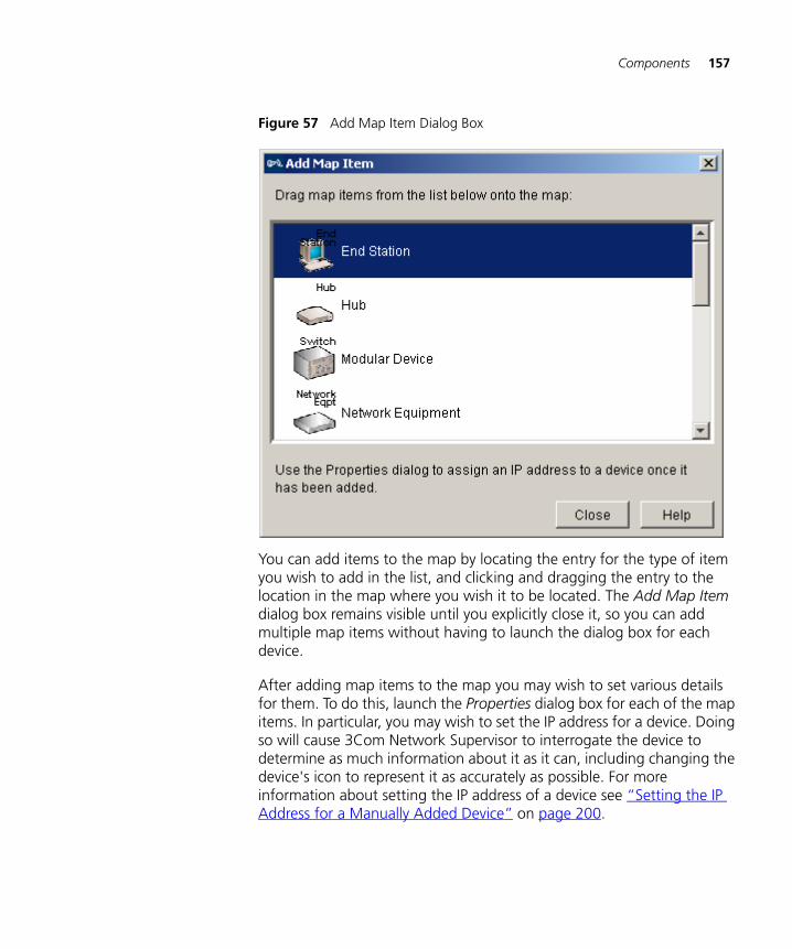
Components 157
Figure 57 Add Map Item Dialog Box
You can add items to the map by locating the entry for the type of item you wish to add in the list, and clicking and dragging the entry to the location in the map where you wish it to be located. The Add Map Item dialog box remains visible until you explicitly close it, so you can add multiple map items without having to launch the dialog box for each device.
After adding map items to the map you may wish to set various details for them. To do this, launch the Properties dialog box for each of the map items. In particular, you may wish to set the IP address for a device. Doing so will cause 3Com Network Supervisor to interrogate the device to determine as much information about it as it can, including changing the device's icon to represent it as accurately as possible. For more information about setting the IP address of a device see “Setting the IP Address for a Manually Added Device” on page 200.

158 CHAPTER 5: WORKING WITH THE MAP
You can still navigate around the map and between submaps when the Add Map Item dialog box is visible. For more information about map navigation see “Navigation” on page 137. This enables you to add map items to several submaps without having to launch the dialog box for each submap.
A newly added cloud is initially present only in the submap that you add it to. However, as soon as you add a link to the cloud the normal cloud behavior takes over. For more information see “Clouds and Submaps” on page 122.
Linking Items in the Map
Links can be added to the map between two devices, a device and a cloud, or between two clouds. To add a link, select the two map items that you wish to link and select Edit > Add Link. An unvalidated link will be added between the two map items. For more information about unvalidated links see “Unvalidated Links” on page 118.
After adding a link between two devices, or between a device and a cloud, you may wish to set the port or interface that the link is attached to on the device(s). For more information about how to set the port for a device at one end of a link see “Properties Dialog Box for a Node” on page 185.
Deleting Items from the Map
Any map item or link can be deleted from the map by selecting it and selecting Edit > Delete. Deleting an map item or link will remove it from all submaps that it is present in. The only way to re-add a map item is to either re-discover it or use the Add Map Item dialog box.
If you delete an map item or link from the map that is still present in your network and then subsequently rediscover the portion of network that the map item or link is on then 3Com Network Supervisor will rediscover that map item or link and add it back into the map.
If you delete a subnet or device group from the map then all items within that subnet or device group will be removed from the map.
Layer-3 connections cannot be manually deleted from the map. However, if you delete a subnet then all layer-3 connections to that subnet will be automatically removed from the map.

Components 159
Keeping the Map Up-to-date
You should carry out regular rediscoveries of your network to maintain your map topology, and keep it up to date with the physical layout of your network.
This technique is described in “Discovering the Network” on page 61.
Saving and OpeningMaps
To create a new empty map file and launch the Network Discovery wizard select File > New. You are prompted to save the map if the current map has changed.
Saving the map stores all of the information about the current map to a set of map files. These include such information as:
■ The devices in your network and their attributes.
■ The topology of your network and how it is laid out within the map.
■ The events associated with your network.
■ Navigation details, including the currently viewed submap and the zoom levels and pan settings for all submaps.
■ The options currently selected in the Tools > Options dialog box and the View menu.
If you choose to either exit 3Com Network Supervisor or open another map, 3Com Network Supervisor may prompt you to save the map. This will occur if:
■ The map was newly created and has never been saved.
■ Any of the above information has changed since the map was last saved.
If you intend, in the future, to manage the same portion of network that is currently discovered in the map 3Com recommends that you save the map. This will prevent you having to rediscover that portion of network when you next wish to view it.
It is good practice to save your map at regular intervals. To do this select File > Save. If the map is a newly created map and has never been saved then you will be prompted for a file name to save the map files under. If you have already saved the map and wish to save it under a new name, select File > Save As, which will prompt you for a new file name.

160 CHAPTER 5: WORKING WITH THE MAP
If you make changes to the above information in a map that you have opened, or if you create a new map, and you do not subsequently save it, then all the information associated with the map will be lost.
Once you have saved a map you can exit 3Com Network Supervisor, or use another map, and then later restore the saved map at the point where you saved it. To restore a saved map select File > Open and locate the map that you wish to open.
3Com Network Supervisor retains a history of the saved maps that have been used. When you launch 3Com Network Supervisor, and have previously saved maps, the Welcome screen offers you the option of opening the most recently used map. Similarly, the File menu includes a list of the four most recently used saved maps. Selecting one of these entries in the File menu will open that map.
Default Map Location
By default, 3Com Network Supervisor saves maps into and opens maps from the following location:
Installation Directory\maps\my_maps (where Installation Directory is the directory where 3Com Network Supervisor is installed)
You can change this location when you are opening or saving maps via the standard file browse dialog box. However, when you next wish to open or save a map the file browser will be launched back to the default location.
If the default location is not suitable, you can change it by launching the Tools > Options dialog box and, from the General tab, either browsing for a new default location, or manually entering the required default location in the Map files field.

Components 161
Figure 58 Default Map File Location
You may wish to select a default location that is backed-up regularly, such as on a file server, in order to ensure that you do not lose any saved maps in the event of hardware failure.

162 CHAPTER 5: WORKING WITH THE MAP
Printing the Map Selecting File > Print launches the Print Map dialog box, which allows you to select how to print the currently visible map:
Figure 59 Print Map Dialog Box
■ Selecting the Print the currently visible area option will reproduce exactly what is displayed on the screen in the printed output. This means that if your map is zoomed out far enough that device labels are not shown, they will not be included in the printed output.
■ Selecting the Print the whole map option will print out the whole of the currently viewed submap, zoomed so that it will fit onto the printed page. Depending upon the size of the currently viewed submap, this also may result in the device labels not being visible in the printed output.

Examples 163
Examples The following section provides some examples of how to perform common tasks with the map and tree.
Selecting all of theSuperStack 3 Switch4400 Devices in the
Network
You wish to locate and select all of the SuperStack 3 Switch 4400 devices in your network so that you can run the Capacity report for them. See “Capacity Report” on page 294 of further information.
1 Launch the Find dialog box by selecting Edit > Find
Figure 60 The Find Dialog Box
2 Select Devices from the Find: list.
3 Select Device type from the Search by: list.

164 CHAPTER 5: WORKING WITH THE MAP
Figure 61 The Search by: List
4 Select 3Com Switch 4400 from the Device type: list.
Figure 62 Selection on the Device type: List
5 Click Find to search for the devices, and wait until the search has completed.

Examples 165
Figure 63 Search Results Table
6 Select a row in the results table and then press Ctrl + A to select all of the SuperStack Switch 4400 devices in your network.
Figure 64 Devices Selected
7 Select Tools > Reports to launch the capacity report.

166 CHAPTER 5: WORKING WITH THE MAP
Viewing all of thePhysical Connections
for a Router
You are currently viewing the devices in your network grouped by subnet and need to see all of the physical connections for a particular router that is logically connected to multiple subnets.
1 Toggle the View > Group Map by Subnet option to change the map to view the devices without grouping them by subnets. All of the devices discovered in your network are now shown in a single submap with all of their physical links visible.
Figure 65 Viewing Devices without Grouping by Subnets
2 Double-click on the router’s entry in the tree. The map zooms in on the router, and the physical links can be viewed.

Examples 167
Figure 66 Double-Clicking on a Router in the Tree

168 CHAPTER 5: WORKING WITH THE MAP
Focusing in on a Setof Devices in the Map
You are viewing the devices in your network grouped by subnet, are in the top-level map, and wish to focus in on the servers on a particular subnet.
1 Double-click, either in the map or in the tree, on the subnet that the servers are in. The map changes to show the contents of that subnet:
Figure 67 Double-Clicking on a Subnet
2 Locate the servers in the tree. Select the first one with a single click and then use Ctrl + click to add each of the other servers into the selection:

Examples 169
Figure 68 Selection of Multiple Servers
3 Click on the Zoom in button in the toolbar. This centers the display around the selected servers and zooms in:
Figure 69 Zooming In

170 CHAPTER 5: WORKING WITH THE MAP
4 Repeat click on the Zoom in button in the toolbar until the servers are at the level of magnification desired:
Figure 70 Adjusting the Magnification

Examples 171
Adding a Linkbetween Map Items
from DifferentSubmaps
You are viewing the devices in your map grouped by subnet, and you wish to add a link between two devices that are on different submaps.
1 Locate the two devices in the tree, select the first one with a single-click and the second one with Ctrl + click.
Figure 71 Locating the Two Devices
2 Select Edit > Add Link. This will add a link between the two devices, and will add shortcut icons to the appropriate submaps.

172 CHAPTER 5: WORKING WITH THE MAP
Figure 72 Selecting Edit > Add Link
It is not necessary for either of the devices to be visible in the display in order to link them in this way.

Examples 173
Adding a New Deviceon Your Network Into
the Map
You have just connected a new stackable switch to the network, and wish to add it into the map so that you can manage it.
If you are viewing the devices in your network grouped by subnet then you need to locate and navigate to the subnet that the new switch is present on, so that the device is present in the correct submap.
1 Find the submap in the tree and double-click on it to open the submap.
Figure 73 Opening the Submap
2 Select Edit > Add Map Item to launch the Add Map Item dialog box, and locate the stackable switch icon in the list:

174 CHAPTER 5: WORKING WITH THE MAP
Figure 74 Selecting Edit > Add Map
3 Click and drag the stackable switch icon across into the location in the map where you wish the switch to be placed and drop the icon there.
Figure 75 Moving the Stackable Switch Icon

Examples 175
4 Having added the switch, close the Add Map Item dialog, right-click on the new icon and select Properties from the pull-right menu.
Figure 76 Selecting Properties
Use the Properties dialog to set the IP address of the new device. For more information about how do this see “Setting the IP Address for a Manually Added Device” on page 200.
As well as adding in the switch to the map using the Add Map Item dialog, you could also add the switch by rediscovering the subnet that the switch is present on. If you have configured a scheduled discovery then this will happen automatically the next time the scheduled discovery discovers the subnet. For more information about how to rediscover subnets and schedule discoveries see “Discovering the Network” on page 235.

176 CHAPTER 5: WORKING WITH THE MAP
Useful Information and References
The following section provides useful support details related to the map and tree.
Graphical Support forSpecific Device Types
Some device types have specific graphical support in the map. This section provides details of the specific support provided.
NBX Network Telephony Solution
For more information about the specific support provided for NBX systems see “NBX Support” on page 369.
3Com Switch 4007
If you have an Enterprise Management Engine (EME) installed in your Switch 4007 chassis, 3Com Network Supervisor will treat the EME as a blade within the chassis for presentation purposes. As a result, the EME will not be represented as a separate icon on the map, and the Switch 4007 icon will be shown linked to the device that provides the EME with it’s network connection point.
3Com Wireless Access Points
Wireless clients tend to be very transient in terms of connectivity compared to other devices, and may frequently change their point of connection. Rather than displaying these dynamically in the map as they come and go, 3Com Network Supervisor shows a single cloud attached to each Wireless Access Point.
Figure 77 Wireless Access Point Representation

Useful Information and References 177
If a Wireless Access Point is being monitored then 3Com Network Supervisor will monitor the number of clients connected to the Wireless Access Point and dynamically update the contents of the cloud to reflect the results of its monitoring.
Figure 78 Clients Connected to the Wireless Access Point
For more information see “Monitoring the Network” on page 213.
Files Associated with Saved Maps
When a map is saved, 3Com Network Supervisor actually creates or updates three files to contain the contents of that map. The three files are named based upon the name you choose, and are as follows:
Table 30 Saved Map Files
Filename Contents
MapName.map Details of the discovered devices and their attributes, the network topology and how it is laid out, navigation details and the various view options.
MapName.properties Details of various settings such as preferences for viewing events and the settings for the last discovery performed.

178 CHAPTER 5: WORKING WITH THE MAP
For example, if you choose to save a map with the name Corporate Core, the following three files will be created:
■ Corporate Core.map
■ Corporate Core.properties
■ Corporate Core Events.edb
All three files are saved to the location that you specify when you save the map.
CAUTION: Should you wish to move a saved map from one location to another, it is important that you move all three files, otherwise you will lose information related to the map.
MapName Events.edb Details of the events that have occurred against this map.
Filename Contents

6 VIEWING DEVICE DETAILS
Overview This chapter describes how to view detailed information about your networking equipment and apply new settings using the Properties dialog box.
The Properties dialog box is available after the network has been discovered.
It allows you to:
■ View detailed information about the items on the network map.
■ Specify custom information such as Custom Name and Comments for the items on the network map.
■ Change the community strings that 3Com Network Supervisor uses for an individual device, or for several simultaneously.
■ Modify how 3Com Network Supervisor communicates with an individual device, or with several simultaneously.
This chapter covers the following topics:
■ Key Concepts
■ Components
■ Examples
■ Key Considerations

180 CHAPTER 6: VIEWING DEVICE DETAILS
Key Concepts This section outlines the key concepts of working with the Properties dialog box in 3Com Network Supervisor.
Items Supported bythe Properties Dialog
Box
3Com Network Supervisor can display the properties of any item on the network map. This includes:
■ Nodes — a node is an object on the network map that represents a single physical entity. Examples of nodes in 3Com Network Supervisor are:
■ Device — a node that provides repeating, switching or routing capabilities for example a hub, switch, router, or bridge.
■ End station — a node that does not have repeating, switching or routing capabilities for example any PC, Unix workstation, server, or other client machine attached to the network.
■ Phone — a node that has voice over IP (VoIP) capability.
■ Subnets — a subnet is a section of the network in which all devices have an IP address within a defined range.
■ Device Groups — a group represents one or more devices that were grouped using the Edit > Grouping > Group Devices and Edit > Grouping > Move Devices to Group menu options.
■ Clouds — a cloud corresponds to an area of the network map for which 3Com Network Supervisor lacks topology information.
■ Links — a link represents the physical connection between two network nodes.
■ Layer-3 Connection — a layer-3 connection represents the logical connectivity between a router or layer-3 switch and a subnet.
See Chapter 5 for more information on working with the map.
Components
Launching theProperties Dialog Box
After you have discovered the network and 3Com Network Supervisor has created the network map you can view the properties for one or several items on the network.

Components 181
To do this:
1 Select the item(s). You can do this by:
■ Clicking on the item’s icon on the map.
■ Clicking on the item’s name in the network tree.
■ Selecting an area of the network map by dragging the mouse while the left mouse button is pressed.
2 Using the Device > Properties menu option, or right-clicking on the item’s icon on the map and selecting the Properties menu option.
Refer to “Working with the Map” on page 109 for more details on how to find and select map items.
Structure of theProperties Dialog Box
The Tabbed Pane
The information presented in the Properties dialog box is organized by tabs, with each tab corresponding to a topic. For instance General, Unit, Addresses.
To view topical information for an item, simply click the corresponding tab. This displays the information for that topic. For instance, click the Addresses tab to display the IP and MAC addresses for the currently selected item.
Figure 79 shows the tabbed pane for a device.

182 CHAPTER 6: VIEWING DEVICE DETAILS
Figure 79 Tabbed Pane for a Device
Table 31 gives a description of the information displayed for each tab.
Table 31 Description of the Tabs in the Properties Dialog Box
Tab Title Contents
General General information regarding the item, such as name, type and system information.
The information varies depending on the item selected.
Unit General information on the single unit for the device, such as type and system information.
Addresses List of IP and MAC addresses for the item.
Security Security settings for the item, such as the community strings that 3Com Network Supervisor should use to communicate with the item.
Ports Information regarding the ports at each end of the link.
Power over Ethernet
Information regarding the power over Ethernet settings and usage for the selected port at the end of a link.

Components 183
The Device Tree
If the selected map item is a networking device, the left-hand side of the dialog box shows a tree, as shown in Figure 80.
Figure 80 The Device Tree
The tree presents the structure, as units/slots and ports, of the selected device.
Phone Information regarding the selected phone.
Tab Title Contents

184 CHAPTER 6: VIEWING DEVICE DETAILS
The device tree lists the following:
■ Device — this is the root of the tree. It represents the whole device. The label displayed in the tree corresponds to the label displayed on the network map such as Custom Name, System Name, IP Address, etc.
■ Unit — this is displayed under the device tree node if there are at least two units within the device or the device is a chassis. It represents an individual unit within a stack, or a blade within a chassis. The label displayed in the tree corresponds to:
■ The unit index within the stack and the type of unit.
■ The slot index within the chassis and the type of blade.
■ Port — this is displayed under the device tree node if the device consists of only one unit, or under the unit tree node if there are several units within the device or the device is a chassis. It represents an individual port within the unit/blade. The label displayed in the tree corresponds to the port index. If the port is part of an aggregation or is connected, this is also shown. For instance:
■ If Port 12 is not connected and is not part of an aggregation, the label is Port 12
■ If Port 12 is not connected and is part of Aggregated Link 1, the label is Port 12: member of AL1
■ If Port 12 is connected to Device1 and is not part of an aggregation, the label is Port 12: connected to Device1
■ If Port 12 is connected to Device1 and is part of Aggregated Link 1, the label is Port 12: member of AL1
■ IfIndex — this is displayed under the device tree node if the device consists of only one unit, or under the unit tree node if there are several units within the device or the device is a chassis. It represents an individual interface within the unit/blade that could not be mapped to a port on the device. The label displayed in the tree corresponds to the ifIndex and the type of interface. If the port is connected, this is also shown. For instance:
■ If the interface with ifIndex 123 is of type PPP and is not connected, the label is IfIndex 123 PPP.

Components 185
■ Aggregated Link — this is displayed under the device tree node. It represents an individual port aggregation on the device. The label displayed in the tree corresponds to the port aggregation index. If ports within the aggregation are connected, this is also shown. For instance:
■ If no link on Aggregated Link 1 is connected, the label is AL 1
■ If one or several links on Aggregated Link 1 are connected to Device1, the label is AL 1: connected to Device1
By default, only units and aggregated links are displayed in the tree. To display ports within a unit you need to expand the corresponding tree node to view its contents.
To expand a tree node and view the contents, click on the + icon next to the folder icon.
To collapse a tree node and hide the contents, click on the - icon next to the folder icon.
To view information on a specific unit, port, or aggregated link, select the corresponding tree node by clicking on it. This updates the tabbed pane on the right-hand side of the dialog box.
The Properties dialog box shows the tree only if a single map item is selected and that map item is a device.
Properties Dialog Boxfor a Node
The contents of the Properties dialog box for the various types of nodes are similar, but there are some slight differences, as highlighted in the following paragraphs.
Table 32 shows the tabs that are displayed, and the contents of these tabs.
Table 32 The Tabs for a Node
Tab Title Contents
General General information regarding the node, such as name, type and system information.
Custom information, such as Custom Name and Comments
Addresses List of IP and MAC addresses for the item.
Security Community strings used for that device

186 CHAPTER 6: VIEWING DEVICE DETAILS
Properties Dialog Boxfor a Supported
Device
If the map item is a device supported by 3Com Network Supervisor, the Properties dialog box shows a tree on the left-hand side of the dialog box, with the tabbed pane on the right-hand side of the dialog box.
The tree shows the individual ports on the device. Select the port in the tree to view the properties for that port. The tabs available for a port are shown in Table 33.
Table 33 Tabs for a Port
If a port is not operating at its full capacity, this is indicated. For instance it may be operating at 10Mbps when it is capable of 100Mbps, or operating in half duplex when it is capable of full duplex.
The tree also shows the individual interfaces on the device that could not be mapped to ports. Select the ifIndex of the interface in the tree to view the properties for that interface. The tabs available for an interface are shown in Table 34.
Table 34 Tabs for an interface
The tree also shows the aggregated links set up on the device. The tabs available for an aggregated link are shown in Table 35.
Table 35 Tabs for an Aggregated Link
Tab Title Contents
General General settings for the port, such as speed, duplex mode, etc.
Custom information, such as comments
Power over Ethernet
Information regarding the power over Ethernet settings and usage for the selected port at the end of a link.
Tab Title Contents
General General settings for the interface, such as media type, speed, IP address, etc.
Custom information, such as comments
Tab Title Contents
General The settings for the aggregated link, such as speed, duplex mode, LACP state, etc.
Information on the individual ports that form the aggregation.
Power over Ethernet
Information regarding the power over Ethernet settings and usage for the selected port at the end of a link.

Components 187
Supported Device(Stack or Chassis)
If the device is a stack or a chassis device, the tree on the left-hand side of the dialog box shows the device, the units/slots on the device, the ports on each unit/slot and the ifIndices and aggregated links on the device, as shown in Figure 81.
Figure 81 Properties Dialog Box for a Supported Device (Stack or Chassis)
Select the unit/slot in the tree to view the properties for that unit/blade. The tabs available for a unit/slot are shown in Table 36.
Table 36 Tabs Available for a Unit/Slot
Tab Title Contents
General The system information for the unit/blade, such as type, hardware and software version, etc.
Custom information for the unit, such as comments.
Addresses The IP and MAC addresses for the unit/blade.

188 CHAPTER 6: VIEWING DEVICE DETAILS
Supported Device(Single Unit)
If the device is neither a stack nor a chassis device, the tree on the left-hand side of the dialog box shows the device, the ports, interfaces and aggregated links on the device, as shown in Figure 82.
Figure 82 Properties Dialog Box for a Supported Device (Single Unit)
Because it is not possible to view the properties of a unit by selecting it in the tree, an additional Unit tab is available for the device.
That tab shows the information in the same format as the General tab for a unit. See Table 36.
Properties Dialog Boxfor an Unsupported
Device
3Com Network Supervisor cannot list the units, interfaces or ports within a device that it does not support. For this reason, there is no tree on the left-hand side of the dialog box, as shown in Figure 83.

Components 189
Figure 83 Properties Dialog Box for an Unsupported Device
Because 3Com Network Supervisor does not support the device some information might be missing. Whenever information is missing, 3Com Network Supervisor shows N/A indicating that it is not applicable or Unknown indicating that 3Com Network Supervisor could not get the information).
Properties Dialog Boxfor an End station
End Stations usually consist of a single port, so 3Com Network Supervisor does not show a tree on the left-hand side of the dialog box, as shown in Figure 84.

190 CHAPTER 6: VIEWING DEVICE DETAILS
Figure 84 Properties Dialog Box for an End Station
Because end stations are usually unmanaged, some information might be missing. Whenever information is missing, 3Com Network Supervisor shows N/A indicating that it is not applicable or Unknown indicating that 3Com Network Supervisor could not get the information.
If the NBX pcXset software (softphone application) is running on the end station, the Phone tab is also available. See “Phone tab” on page 191 for the contents of that tab.
Properties Dialog Boxfor a Phone
Because phones are unmanaged, 3Com Network Supervisor cannot represent individual port information for them. Because of this there is no tree on the left-hand side of the dialog box, as shown in Figure 85.

Components 191
Figure 85 Properties Dialog for a Phone
Phone tab
The Properties dialog box for phones displays an extra Phone tab. This tab displays information such as:
■ User information for the phone: User title, user name, user department
■ Phone information: Extension number, location
Because phones are unmanaged, some information might be missing. Whenever information is missing, 3Com Network Supervisor shows N/A indicating that it is not applicable or Unknown indicating that 3Com Network Supervisor could not get the information.

192 CHAPTER 6: VIEWING DEVICE DETAILS
Properties Dialog Boxfor a Subnet
Figure 86 Properties Dialog Box for a Subnet
The tabs available for a subnet are shown in Table 37:
Table 37 Tabs available for a Subnet
Properties Dialog Boxfor a Device Group
The Properties dialog box for a device group consists of a single General tab, as shown in Figure 87.
Tab Title Contents
General General and custom information for the subnet, such as custom name, subnet address, comments, etc.

Components 193
Figure 87 Properties Dialog Box for a Device Group
The General tab shows the following information:
■ Custom Name — The name of the device group as it appears on the map.
■ Comments — The custom comment for the device group.
Properties Dialog Boxfor a Cloud
The Properties dialog box for a cloud consists of a single General tab, as shown in Figure 88.

194 CHAPTER 6: VIEWING DEVICE DETAILS
Figure 88 Properties Dialog Box for a Cloud
The General tab shows the following information:
■ Custom Name — the custom name of the cloud.
■ Type — this corresponds to the media types of the links connected to the cloud.
■ Comments — the custom comment for the cloud
Properties Dialog Boxfor a Link
This section describes the Properties dialog box for the various types of links.

Components 195
Properties Dialog Box for a Link
The Properties dialog box for a link between two nodes consists of a tabbed pane. There is no tree on the left-hand side, as shown in Figure 89.
Figure 89 Properties Dialog Box for a Link
The tabs available for a link are shown in Table 38:
Table 38 Tabs Available for a Link
Tab Title Contents
General General information for the link, such as speed, duplex mode, etc.
Custom information, such as comments.

196 CHAPTER 6: VIEWING DEVICE DETAILS
Properties Dialog Boxfor a Layer-3
Connection
The Properties dialog box for a Layer-3 Connection consists of a tabbed pane. There is no tree on the left-hand side, as shown in Figure 90.
Figure 90 Properties Dialog Box for a Layer-3 Connection
Ports Information for the devices at each end of the link such as device name and IP address.
Settings for the port at each end of the link such as port number, auto-negotiation settings, spanning tree state, etc.
Power over Ethernet Information regarding the power over Ethernet settings and usage for the ports at either end of the link.
Tab Title Contents

Components 197
The tabs available for a link to a subnet are shown in Table 39:
Table 39 Tabs available for a Layer-3 Connection
Properties Dialog Boxfor a Multiple
Selection
When multiple items are selected on the map and the Properties dialog box is launched, no tree is available on the left-hand side. Instead explanatory text is displayed, as shown in Figure 91.
Figure 91 Properties Dialog Box for a Multiple Selection
The tabs shown in the tabbed pane depend upon the items that have been selected:
■ If the selected items are all of the same type (for example, if they are all physical links, or if they are all devices) then the standard tabs for that type will be shown.
Tab Title Contents
General General information about the source of the layer-3 connection on the device end of the link, such as details of the IP interface and the ports it is associated with.

198 CHAPTER 6: VIEWING DEVICE DETAILS
■ If the selected items are of different types then the General tab will be shown, containing only the Comments section. In addition, if the Security tab would be displayed for any of the selected items if the Properties dialog box was launched for them individually then the Security tab is also displayed.
For example, if three links are selected, one of which is an aggregated link, and the Properties dialog box is launched then the General and Ports tabs will be displayed; if a node were added to the selection prior to launching the Properties dialog box then the General and Security tabs would be displayed.
If, for any tab, it is not possible to display information common to the whole selection, the tab shows explanatory text, as shown in Figure 92.
Figure 92 No Common Information Across the Selection
Where possible, 3Com Network Supervisor displays the original layout for each tab.
If the information for a field within a tab is the same for all selected items, that information is displayed. If the information differs between the items, the information shows multiple values.
For example, Figure 93 shows a section of the General tab for two devices of the same type (3Com SuperStack 3 Switch 4226T). The Type and Product Number are the same for both devices, so the actual value is displayed for both the Type and Product Number fields. However, the Serial Number is different for the two devices, so the value for Serial Number shows multiple values.
Figure 93 General Tab for Two Devices of the Same Type
Components 199
Applying Changes toDevices Using the
Properties Dialog Box
This section describes how you can apply changes to items with the Properties dialog box.
Changing the Custom Name
3Com Network Supervisor allows you to change the custom name of any item on the network map.
To change the custom name of an item on the map:
■ Click on the icon for the node in the 3Com Network Supervisor map to select it.
■ Select the Device > Properties menu option to launch the Properties dialog box.
■ In the General tab, enter the label you want to use in the Custom Name field.
■ Click OK to validate your changes.
To show the custom name of the items on your network, select the View > Labels > Custom Name menu option.
Changing the Custom Name only changes the label that 3Com Network Supervisor uses for the network map – if you are changing the label for a device then 3Com Network Supervisor makes no changes to the device itself.
Changing the Comments
3Com Network Supervisor allows you to specify comments for any item on the network, including the units, ports and interfaces on a node.
To specify comments:
1 Click on the icon for the item in the 3Com Network Supervisor map to select it.
2 Select the Device > Properties menu option to launch the Properties dialog box.
3 To specify a comment for any item type other than a unit, port or interface, type in your comment in the Comments section of the General tab. If you want to enter comments for a unit, port or interface, select that item in the tree on the left-hand side of the dialog box, then type in your comment in the Comments section of the General tab for that item.

200 CHAPTER 6: VIEWING DEVICE DETAILS
4 Click OK to save your changes.
Setting the IP Address for a Manually Added Device
When a device is manually added to the map, it does not have an IP address associated with it. 3Com Network Supervisor lets you enter an IP address for that device.
To specify the IP address for a manually added device:
1 Click on the icon for the device in the 3Com Network Supervisor map to select it.
2 Select the Device > Properties menu option to launch the Properties dialog box.
3 Click on the Addresses tab. This displays the tab as shown in Figure 94.
4 Click on the Assign button and enter the IP address for that device in the Add IP Address dialog box, then click OK.
The IP address must be a valid address, must be within the range allowed for the subnet the device was added to, and must not be already used by another device; otherwise a warning message is displayed.
5 3Com Network Supervisor then tries to contact the device using the IP address you specified. If the IP address does not respond, the dialog box shown in Figure 95 is displayed: Click No to enter a different IP address or Yes to use the IP address you specified.
6 Click on OK in the Properties dialog box to validate your changes.
The IP information is now set and the device is now recognized by 3Com Network Supervisor as a valid device.
When the changes are validated, 3Com Network Supervisor attempts to automatically recognize the type of the device. As a result, the icon representing the added device on the map might change to better reflect the actual type recognized.

Components 201
Figure 94 Addresses Tab for a Manually Added Device
Figure 95 Cannot Contact the IP Address Specified
Assigning an IP address to a manually added device only defines the IP address that 3Com Network Supervisor uses to communicate with the device – it does not assign the IP address to the device itself.

202 CHAPTER 6: VIEWING DEVICE DETAILS
Setting the Port Numbers for a Manually Added Link
When a link is manually added to the map, it does not specify which ports or interfaces are being used on the devices it connects. 3Com Network Supervisor lets you enter which ports or interfaces are used for the link.
To specify port information for a manually added link:
1 Click on the icon for the link in the 3Com Network Supervisor map to select it.
2 Select the Device > Properties menu option to launch the Properties dialog box.
3 Click on the Ports tab. This displays the tab shown in Figure 96.
4 Click on the Set button and select the unit, if applicable, and port or interface on which the link is connected for the From port in the Add Port dialog box. Click OK. The port or interface being used for the From device is now listed.
5 Click on the Set button and select the unit, if applicable, and port or interface on which the link is connected for the To port in the Add Port dialog box. Click OK. The port or interface being used for the To device is now listed.
You can only select a port or interface that is not already connected. If a port or interface is already connected it is not displayed in the list of available ports.
Warning: If the device at one end of the link is not supported or consists of a single port, for example an end station, there are no ports available so a message is displayed instead of the Add Port dialog box.
6 Click on OK in the Properties dialog box to validate your changes.
The port information is now set.

Components 203
Figure 96 Ports Tab for a Manually Added Link
Changing theCommunity Strings
for a Device
It is possible to specify which community strings 3Com Network Supervisor should use to communicate with a device.
This can be useful if a device has had its community strings changed since it was first discovered and you want to change the community strings that 3Com Network Supervisor uses so that you can continue to monitor it, or if a new device has been manually added to the 3Com Network Supervisor map and you want to specify the community strings that should be used to communicate with it.

204 CHAPTER 6: VIEWING DEVICE DETAILS
To change the community strings on a device:
1 Click on the icon for the device in the 3Com Network Supervisor map to select it.
2 Select the Device > Properties menu option to launch the Properties dialog box.
3 Select the SNMP tab. This shows the tab shown in Figure 97.
4 If you do not want to use the default community strings for that device, click the Specify option. This enables the Read and Write fields.
5 Enter the new community strings in the Read and Write sections.
6 Click OK to validate your changes.
3Com Network Supervisor attempts to use the specified community strings to communicate with the device. If the strings provided are not accepted by the device, 3Com Network Supervisor shows the dialog box in Figure 98. If you want to return to the existing community strings, select Ignore the new settings and click OK; if you still want to use the community strings you specified, select Apply the new settings and click OK.

Components 205
Figure 97 Security Tab for a Device

206 CHAPTER 6: VIEWING DEVICE DETAILS
Figure 98 Community Strings Not Accepted
Once the changes are applied 3Com Network Supervisor uses the new community strings to communicate with the device.
Changing the community strings for a device only changes the community strings that 3Com Network Supervisor uses to communicate with the device, it does not change the community strings on the device itself.

Examples 207
Examples The following section details examples of using the Properties dialog box.
How Do I View the Properties of a Specific Port on a Device?
You want to check the settings of port 5 on slot 4 of your 3Com Switch 4007.
To View the Properties for that port:
1 Click on the icon for your Switch 4007 on the map to select it.
2 Select the Device > Properties menu option to launch the Properties dialog box.
3 To expand the tree and display all the ports on Slot 4 of your Switch 4007 click on the + sign beside the tree branch corresponding to Slot 4 on the left-hand pane of the dialog box.
4 Select Port 5 in the tree to show the properties for that port.
The properties for that port are now displayed, as shown in Figure 99.
Figure 99 Properties for a Specific Port

208 CHAPTER 6: VIEWING DEVICE DETAILS
How Do I Change the Community Strings for All Devices in a Subnet?
You have changed the community strings for all devices in a subnet, and want 3Com Network Supervisor to use these community strings to communicate with these devices.
To change the community strings for all devices in a subnet:
1 Click on the icon for the subnet in the 3Com Network Supervisor map to select it.
2 Select the View > Enter Submap menu option to display the contents of the subnet.
3 Select the View > Select All menu option to select all items within the subnet.
4 Select the Device > Properties menu option to launch the Properties dialog box.
5 Select the Security tab.
6 Click the Specify option. This enables the Read and Write fields, as shown in Figure 100.
7 Enter the new community string in the Read and Write sections.
8 Click OK to validate your changes.
3Com Network Supervisor now uses the community strings you specified to communicate with the selected devices.

Examples 209
Figure 100 Security Tab for Multiple Devices
How Do I Find the Version of the Agent Software on a 3Com Device?
You want to check the version of the software running on your 3Com switch.
To see the software version running on your switch:
1 Click on the icon for the switch in the 3Com Network Supervisor map to select it.
2 Select the Device > Properties menu option to launch the Properties dialog box.
The software version is displayed in:
The Unit tab for the device, if the switch is a single-unit. The General tab for the unit if the switch is part of a stack.

210 CHAPTER 6: VIEWING DEVICE DETAILS
3 In that case, select the corresponding unit in the tree in the left-hand pane of the dialog box
To view the software version for a blade in a chassis, select the corresponding Slot in the tree in the left-hand pane of the dialog box.
Key Considerations The following section provides assistance when working with device properties.
Troubleshooting Some advice on errors that may occur on the system is given below:
There Is No Port Information For My Device
The Properties dialog box for the device you selected does not show a tree on the left-hand side, so it is not possible to view the properties of individual ports on that device.
The most likely reason for this is that 3Com Network Supervisor does not support the device. For devices that are not supported by 3Com Network Supervisor, neither unit or port information can be extracted, so no properties can be viewed for either a unit or a port on that device. Ensure that 3Com Network Supervisor supports the device.
It is also possible that the SNMP requests that 3Com Network Supervisor uses to communicate with the device timed out. If this is the case then the Discovery report will indicate that this problem occurred during discovery. For more information on this report see “The Discovery Report”on page 94.
There Is No General Unit Information For My Device
The Properties dialog box for the device you selected shows a tree on the left-hand side, but no unit is listed in the tree, so you cannot view the General tab for that unit.
In a case where the device consists of a single unit, the general properties of that unit can be viewed from the Unit tab for the device.
A Lot of Fields in the Properties Dialog Box Show Unknown
Many of the fields displayed in the Properties dialog box show Unknown.

Key Considerations 211
There are several reasons why this happens:
■ The device you selected is not fully supported by 3Com Network Supervisor: If the device is not fully supported by 3Com Network Supervisor the necessary information cannot be collected. For these fields, 3Com Network Supervisor shows Unknown. Ensure that the device is fully supported by 3Com Network Supervisor.
■ The SNMP requests used by 3Com Network Supervisor to discover the device timed out. If this is the case then the Discovery report will indicate that this problem occurred during discovery. For more information on this report see “The Discovery Report” on page 94.
It Takes a Long Time to Close the Dialog Box After Assigning an IP Address to a Manually Added Device
You assigned an IP address to a manually added device and the Properties dialog box takes a long time before closing. During that time, a message is displayed which reads: Please wait while the new properties are verified and applied.
This is normal. When an IP address is assigned to a manually added device, 3Com Network Supervisor checks whether the device is available on the network; if it is it retrieves the device name, type and other properties from the device, verifies them and updates the map, which explains the time required. It usually takes at least one minute for 3Com Network Supervisor to carry out those changes.

212 CHAPTER 6: VIEWING DEVICE DETAILS

7 MONITORING THE NETWORK
Overview This chapter describes how 3Com Network Supervisor can be used to monitor the status of the devices and links within your network.
Monitoring the status of devices and links within your network allows you to identify possible bottlenecks or trouble spots in the network before they cause a major impact, and can be used to assist in troubleshooting when issues arise.
This chapter covers the following topics:
■ Key Concepts
■ Components
■ Configuration
■ Examples
■ Key Considerations
Key Concepts This section describes the key concepts associated with monitoring your network using 3Com Network Supervisor.
Monitor A monitor is a counter or status indicator for a device or link that collects data about one of its attributes, such as the number of packets a device has been sent, or whether a link is up or down. A device or link may have multiple monitors that provide a complete picture of the network conditions that it is experiencing.
Some monitors, for example, the Link Availability monitor, only indicate whether an attribute is in a good state or a bad state. These are termed bi-state monitors. All other monitors can indicate a large range of values for the attribute they monitor, and are termed multi-state monitors.

214 CHAPTER 7: MONITORING THE NETWORK
Monitoring and EventGeneration
The monitoring system is used as the main source for generating events. When a monitor enters a state that indicates an abnormal network condition it logs an event detailing the cause. Depending upon the monitor it may also log details of the monitoring state in the time immediately preceding and following the event. When the monitor later exits this state it resolves the event. This information can be used either immediately or at a later date to determine the cause of the event and to assist with determining a resolution.
For more information on the events system see “Working With Events” on page 235.
The monitor states that indicate abnormal network conditions are based upon thresholds. For more information see “Setting Thresholds for Monitor-Based Events” on page 264.
Monitoring State 3Com Network Supervisor indicates the monitoring state of each monitored device by coloring the background of its icon in the map and its node in the tree using one of red, yellow or green. Similarly, the monitoring state of each monitored link is indicated by drawing the link in the map in red, yellow or green, rather than in black. This allows you to see at a glance the current state of your network so that you may quickly identify trouble spots.

Key Concepts 215
Figure 101 Example of how the Monitored State is Displayed on the Map
The color of a monitored item represents the highest severity unresolved event for that item, as shown in the table below:
Table 40 Map Item Color Key
This coloring scheme also allows you to quickly determine if a device or link is being monitored: monitored items are colored and unmonitored items are not.
Color Description
Red There are unresolved events for the item and the highest has a high, critical or recurring severity.
Yellow There are unresolved events for the item and the highest has a warning severity.
Green There are no unresolved events for the item.
None None The item is not being monitored.

216 CHAPTER 7: MONITORING THE NETWORK
For details on how to start monitoring an unmonitored device or link, or to stop monitoring a monitored device or link, see “Starting and Stopping Monitoring” on page 227.
For more information on event severities see “Event Severities” on page 237
Monitoring State and the Grouped View
When you are viewing the devices in your network grouped by subnet, 3Com Network Supervisor propagates the monitoring states of devices, links and submaps up the submap hierarchy. Each submap is colored to indicate the most critical monitoring state of the devices, links or submaps that it contains.
For example, if a subnet contains two devices, one of which has a red monitoring state and one of which has a yellow monitoring state, the subnet will be colored red. If the event causing the red device's monitoring state is subsequently resolved, the subnet will change to be colored yellow, as this is now the most critical monitoring state contained within the subnet.
When determining the monitoring state of a submap, 3Com Network Supervisor ignores any map items or links that are visible at a higher level in the hierarchy than the submap itself. For example, the monitoring state of a router will not affect the monitoring state of the subnets that it is present on, as the router is visible further up the hierarchy.
MonitoringTechniques
3Com Network Supervisor uses various techniques to monitor the state of devices and links within your network. The techniques used for a particular monitor depend upon the feature that is being monitored, and can be broadly broken down into active and passive monitoring:
Active Monitoring: Active monitoring works by 3Com Network Supervisor polling, and possibly retrieving data from, a device on a regular basis. Once the device has been polled, or once the data has been retrieved from the device, 3Com Network Supervisor can analyze the results to determine the state of the device. There are various mechanisms used for active monitoring, including sending IP pings, retrieving data from SNMP MIBs, and directly checking for service availability.

Key Concepts 217
The rate with which an active monitor polls depends upon the type of device that is being polled, the active monitoring mechanism used and the polling configuration.
Passive Monitoring: Passive monitoring relies upon a device monitoring its own state and sending unsolicited messages to 3Com Network Supervisor whenever its state changes, providing details of the change. Passive monitoring uses SNMP traps to send this data.
As active monitoring relies upon regular polling, whereas passive monitoring only sends data when a device’s state changes, active monitoring generates more network traffic than passive monitoring. However, active monitoring is a more reliable and deterministic means of monitoring the status of network devices.
IP Ping Monitoring
The simplest monitoring technique used by 3Com Network Supervisor is IP ping monitoring. This is an active monitoring technique that works by 3Com Network Supervisor sending an ICMP ping message to the device being monitored and using the response time, or lack of a response, to update the state of the monitor it is being used for.
SNMP MIB Data Retrieval
Many network infrastructure devices maintain statistics about their operation, which may include such details as the number of packets sent and received on each port or the status of their components, and allow access to this information via SNMP MIBs. When 3Com Network Supervisor is monitoring a device or link using an SNMP MIB-based monitor, 3Com Network Supervisor uses SNMP v1 to request particular MIB values on a regular basis. The information returned from the device’s MIB is then used, sometimes in conjunction with previously retrieved information, to update the state of the monitor.
SNMP MIB data retrieval is an active monitoring technique.
A particular SNMP MIB-based monitor may rely upon a single MIB value or multiple MIB values. 3Com Network Supervisor optimizes its retrieval from devices so that it only retrieves those MIB values relevant to the monitors that are currently running. For more details on how to restrict monitoring to only those monitors that you are interested in see “Disabling and Enabling Individual Monitors” on page 228.

218 CHAPTER 7: MONITORING THE NETWORK
Service Polling
3Com Network Supervisor provides support for monitoring the status of various services that may be provided by servers in your network, including such services as DNS, FTP, POP3 and SMTP mail. 3Com Network Supervisor monitors a service by connecting to and sending a request to the service on a regular basis. The response received, or the lack of any response, is used by 3Com Network Supervisor to update the state of the monitor.
Depending upon the service being monitored, the monitor may be able to use the response to determine more than just the responsiveness of the service i.e. how quickly the response is received. Some services, such as DNS, support status requests to which they respond with details of the internal status of the service. 3Com Network Supervisor will use these status requests when they are available to provide more detailed information about the service status.
SNMP Trap Receipt
Network infrastructure devices that maintain statistics about their operation and allow access to this information via SNMP MIBs often also support the concept of SNMP traps. SNMP traps are unsolicited messages sent out by the devices when the data stored in the SNMP MIB indicates that the device is in certain states. These may indicate simple state changes such as a port going up or down, or may indicate more complex state changes, such as the received packet rate reaching a particular level.
Devices that support SNMP traps are known as trap sources. In order for another device to receive the SNMP traps from a trap source it must register with the trap source as a trap destination. When a trap source enters a state for which it will generate an SNMP trap it sends the trap to all registered trap destinations.
SNMP trap receipt is the only passive monitoring technique used by 3Com Network Supervisor. 3Com Network Supervisor attempts to register the PC it is running on as a trap destination with all monitored network infrastructure devices that support SNMP traps. When 3Com Network Supervisor receives an SNMP trap it determines whether or not it has a monitor associated with the trap type. If it does then the trap is used to update the state of the monitor.

Key Concepts 219
If an SNMP trap is received that does not have a monitor associated with it then 3Com Network Supervisor will use the trap to generate an event directly. For more information see “The Event Log” on page 235
See “Registering 3Com Network Supervisor as an SNMP Trap Destination” on page 229 for more information on controlling how 3Com Network Supervisor registers itself with SNMP trap sources as an SNMP trap destination.
Monitor-able Items 3Com Network Supervisor can monitor most devices and links that are displayed in the map, including:
■ Network infrastructure devices
■ Servers
■ End stations
■ NBX phones
■ Ethernet links, including aggregated links
The particular attributes that can be monitored for a device or link depend upon the exact type of device or link that is being monitored.
Monitoring Non-3Com Devices
3Com Network Supervisor will monitor most non-3Com network devices to some extent. However, as some non-3Com devices do not present their statistics in a standard manner, 3Com Network Supervisor is unable to provide full monitoring support for non-3Com devices. In particular:
■ 3Com Network Supervisor will not monitor features on non-3Com devices whose statistics are presented via proprietary mechanisms.
■ 3Com Network Supervisor will not register or de-register itself as an SNMP trap destination with non-3Com devices.
Link Monitoring When you start monitoring for a link, 3Com Network Supervisor starts monitoring for the devices at the ends of that link automatically. The monitors for the link then use the data gathered by one or both of the devices for the port(s) that the link connects to in order to provide the data that they require. For monitors which use only one device, the selection of which device to use as the data source for a link’s monitors is performed automatically, and is based upon which device provides the most detailed information about the link. The algorithm used is:

220 CHAPTER 7: MONITORING THE NETWORK
■ If neither end of the link can be monitored then the link cannot be monitored.
■ Otherwise, if one end of the link cannot be monitored then use the other end.
■ Otherwise, if only one end of the link is currently being monitored then use that end.
■ Otherwise, if port information is only available for one end of the link then use that end. Note that full port information may not be available for non-3Com devices.
■ Otherwise, if only one end of the link is being fully monitored then use that end, for example, if the other end is in response monitoring mode.
■ Otherwise, if only one end of the link supports high-capacity RMON counters then use that end.
■ Otherwise, pick an end at random.
3Com Network Supervisor will reassess the device to be used as the data source whenever you stop or start monitoring on either of the devices at the ends of the link:
■ If you stop monitoring on the device that has been selected as the data source for the link then 3Com Network Supervisor will automatically switch across to using the device at the other end of the link as the data source.
■ If you subsequently restart monitoring on that device then 3Com Network Supervisor will automatically switch back to using that device as the link’s data source.
Components This section describes the components that may be used to view monitoring information for the devices and links in your network.
Live Graphs Window To view the live data for the monitors associated with a device or link, select the item you are interested in and then either select Monitoring > Live Graphs, or right-click on the item and select Live Graphs window from the item’s right-click menu. This launches the Live Graphs dialog box for the item:

Components 221
Figure 102 Live Graphs Window
The Live Graphs window has a similar layout to the Main Window, with a menu and toolbar at the top and a tree at the left-hand side. However, it uses the right-hand side of the display to show live graphs for monitors.
Poll Rates
When the Live Graphs window is displayed for a particular device or link 3Com Network Supervisor increases the poll rate for the active monitors of the device or link to every 10 seconds in order to provide you with more detailed graphs. The poll rate for the active monitors of the device or link revert to their normal settings when you close the Live Graphs window.
Live Graphs Tree The contents of the tree depend upon the map item that the graphs are being shown for:
■ For devices, the tree shows a hierarchical breakdown of the components of that device.
■ For modular devices the hierarchy lists the device as the top-level folder, the modules as folders at the next level and the known links to the device as nodes within the appropriate modules at the lowest level.
■ For stacked devices the hierarchy lists the stack as the top-level folder, the units as folders at the next level and the known links to the device as nodes within the appropriate units at the lowest level.

222 CHAPTER 7: MONITORING THE NETWORK
■ For other devices the hierarchy lists the device as the top-level folder and the known links to the device as nodes below that.
Selecting the top-level folder, which is the default, changes the displayed live graphs on the right-hand side of the display to graphs of the monitors that monitor the general state of the device. Selecting a link node changes the displayed live graphs on the right-hand side of the display to graphs of the monitors that monitor the state of the link.
■ When you launch the Live Graphs window for a link, the tree lists the link as the top-level folder, and the right-hand side of the display shows live graphs for all of the link’s monitors.
Live Graphs Display The live graphs display area, on the right-hand side, shows live graphs for the states of the monitors relevant to the item selected in the tree. Each monitor’s entry shows the name of the monitor that the graph is for and the graph itself:
Figure 103 Live Graph Display
The graph displays the historical state of the monitor. For example, for the IP Ping Service monitor, the graph displays a history of the IP ping response time for the device.
Each monitor has a menu that can be launched by right-clicking on the monitor’s live graph. Some items in the menu are not always applicable. When this is the case, the menu option is grayed out.
The operations provided by the right-click menu are equivalent to their corresponding main menu items. See “Live Graphs Menu” on page 224 for more information.
Displaying Thresholds
Each monitor has a configurable threshold associated with it that represents an abnormal, or high, state for that monitor. For multi-state monitors, 3Com Network Supervisor also automatically determines an appropriate warning threshold for the monitor.

Components 223
These thresholds are used mainly for event generation: if a monitor stays in the warning or high state long enough then it will generate an appropriate event.
When a graph for a multi-state monitor includes values that are near or exceed the warning threshold a yellow horizontal dashed line is displayed on the graph to indicate the warning threshold level. Additionally, if the graph includes values that are near or exceed the high threshold a red horizontal dashed line is displayed on the graph to indicate the high threshold level.
It is possible to force the Live Graphs window to always show the thresholds for each multi-state monitor displayed in the live graphs display area by enabling the View > Display thresholds option. This option is enabled by default.
If a graph does not include values that are near or exceed either of the thresholds, enabling this option allows you to see how close a monitor is to its threshold values while disabling the option allows you to view more detail on the monitor’s trends.
The difference between the two can be seen in the two graphs of the same monitor that are shown below:
Figure 104 Displaying Thresholds for Live Graph With Below-Threshold Values (Forcing display of Thresholds and Not Forcing display of Thresholds)
If a graph does include values that are near or exceed the high threshold, then both thresholds will already be visible on the graph. Enabling or disabling this option in this case will have no effect on the graph.

224 CHAPTER 7: MONITORING THE NETWORK
Regardless of whether the option is enabled or not, the graphed line that shows the historical monitor state is also color-coded to show the state of the monitor throughout its history: green for those times when it was normal (i.e. below the warning threshold), yellow for warning and red for high.
Threshold lines are not displayed for bi-state monitors. However, these monitors still color-code the graphed line to represent the state: green for the good state and red for the bad state. For example:
Figure 105 Bi-State Monitors State Representation
For more information on thresholds, see “Setting Thresholds for Monitor-Based Events” on page 264
Live Graphs Toolbar
The toolbar provides access to the most commonly used monitor tools.
Some items in the toolbar are not always applicable. When this is the case, the toolbar button is grayed out.
Hovering the mouse cursor over a button in the toolbar causes a tooltip for that button to be displayed. The tooltip describes the operation associated with the button.
The operations provided by the toolbar buttons are equivalent to their corresponding menu items. See “Live Graphs Menu” on page 224 for more information.
Live Graphs Menu The following tables list each menu item for a given menu in the Live Graphs window and the associated operation invoked by selecting it.
Table 41 Live Graphs - File Menu
Menu Item Hot Key Operation
Close Closes the Live Graphs dialog box.

Components 225
Table 42 Live Graphs — Monitor Menu
Table 43 Live Graphs — View Menu
Table 44 Live Graphs - Help Menu
More Detail DialogBox
To view more detail on a particular monitor, either right-click on its entry in the live graph display area of the Live Graphs window and select More detail from the right-click menu or select its entry in the live graph display area of the Live Graphs window and select Monitor > More detail. The More Detail dialog box is shown below:
Menu Item Hot Key Operation
More detail Launches the More Detail dialog box for the selected monitor. See “More Detail Dialog Box” on page 225 for more information.
Change thresholds Launches the Threshold Settings dialog box for the selected monitor. See “Setting Thresholds for Monitor-Based Events” on page 264 for more information.
Disable this monitor Disables the selected monitor on or off. See “Disabling and Enabling Individual Monitors” on page 228 for more information.
Enable this monitor Enables the selected monitor. See “Disabling and Enabling Individual Monitors” on page 228 for more information.
Menu Item Hot Key Operation
Display thresholds Toggles the forcing of the display of scaling of the monitors’ mini-graphs to the thresholds set for the monitors in their mini-graphs. See “Displaying Thresholds” on page 222 for more information.
Menu Item Hot Key Operation
Help on this window Launches the online help topic for the Live Graphs window.

226 CHAPTER 7: MONITORING THE NETWORK
Figure 106 More Detail Dialog Box
The More Detail dialog box provides in-depth information about the selected monitor.
The main body of text describes what attribute the monitor is monitoring, details the current state of the monitor and, if the monitor is in an abnormal state, describes what may be causing the problem and potential resolutions.
Clicking the blue underlined title of the monitor in the main body of text will bring the Live Graphs window that the More Detail dialog box was launched from to the front, re-launching it if necessary, and will locate and select the monitor within that dialog box.
The absolute value and the threshold for the monitor are shown below this. In addition, if the monitor is in an abnormal state then the number of events generated by this monitor in the last day and the last week will also be shown on the right.
The information displayed in the More Detail dialog box is not dynamic. If you launch the More Detail dialog box when a monitor is in an abnormal state and it subsequently returns to a normal state, the More Detail dialog box will continue to display details of the abnormal state.

Configuration 227
As well as providing details of the selected monitor, the More Details dialog box also allows you to configure the monitor via the Change thresholds and Disable this monitor buttons. See “Setting Thresholds for Monitor-Based Events” on page 264 and “Disabling and Enabling Individual Monitors” on page 228 respectively for more information.
Configuration The following section describes how to configure the monitoring system so that it provides the data that you require in managing your network.
Starting andStopping Monitoring
Before 3Com Network Supervisor can generate events for devices in your network you must first start monitoring on those devices. This can be performed automatically from the Network Discovery Wizard. However, you may wish to modify the set of monitored devices and links to focus only on specific items in your network, you may wish to exclude specific sections of the network from monitoring, or you may wish to reduce the amount of network traffic generated by 3Com Network Supervisor’s active monitors.
To start monitoring on a set of devices and links, select the items that you want to start monitoring and select either Monitoring > Start Monitoring from the main menu or Start Monitoring from the right-click menu. If your selection includes a subnet or device group then 3Com Network Supervisor will recursively start monitoring on all core devices and links in that group that are not visible at a higher level in the map.
3Com Network Supervisor will automatically start monitoring for an unmonitored device or link if you launch the Live Graphs window for it.
Stopping monitoring on a set of devices and links can be performed in a similar manner to starting monitoring, but by selecting either Monitoring > Stop Monitoring from the main menu or Stop Monitoring from the right-click menu instead.
When you stop monitoring for a device or link, 3Com Network Supervisor automatically resolves any unresolved events for that item that were generated by active monitors. Unresolved events for the device that were generated by SNMP traps or passive monitors remain unresolved. If you have the Live Graphs window open for the item then these will be automatically closed.

228 CHAPTER 7: MONITORING THE NETWORK
When you stop monitoring for a 3Com device, 3Com Network Supervisor may also de-register itself as an SNMP trap destination, if the device has no other features that require 3Com Network Supervisor to remain registered.
3Com Network Supervisor will never generate events for a device or link that is not being monitored.
Disabling and Enabling Individual Monitors
Each monitor provides details of the state of a particular attribute of a device or link. If a particular attribute is of no interest to you, but you still wish to monitor other attributes on a device or link, then you may disable the monitor for that attribute in order to reduce the amount of network traffic generated by 3Com Network Supervisor
Individual monitors can be disabled from the Live Graphs window by selecting the monitor and then selecting either Monitor > Disable this monitor from the main menu or Disable this monitor from the right-click menu. You may also disable a monitor by clicking the Disable this monitor button in the More Detail dialog box.
Similarly, a disabled monitor can be re-enabled from the Live Graphs window by selecting the monitor and then selecting either Monitor > Enable this monitor from the main menu or Enable this monitor from the right-click menu. Monitors cannot be re-enabled from the More Detail dialog box.
When you disable a monitor, all events that rely upon that monitor are automatically disabled. Similarly, when you enable a monitor, all events that rely upon that monitor are automatically enabled. See “Disabling and Enabling Events” on page 261.
When a monitor is disabled the text Switched Off will be displayed over the monitor. In the Live Graphs window the graph is otherwise blank:

Configuration 229
Figure 107 Disabled Monitor Screen
Controlling EventGeneration from
Monitors
3Com Network Supervisor uses monitors to generate events. If a monitor remains in a warning or high state for an extended period of time an event will be generated.
The warning and high states for a monitor are determined from the setting of a threshold for the monitor. This threshold specifies the state that the monitor must reach to enter its high state. 3Com Network Supervisor then derives a warning state from the threshold. For further details on thresholds and how to change them see “Setting Thresholds for Monitor-Based Events” on page 264.
Registering 3ComNetwork Supervisor
as an SNMP TrapDestination
3Com Network Supervisor will attempt to register itself as an SNMP trap destination with any 3Com device that it is monitoring.
3Com Network Supervisor will not register itself as an SNMP trap destination with non-3Com devices when you start monitoring them, nor will it de-register itself when you stop monitoring them.
If you wish 3Com Network Supervisor to receive traps from a non-3Com device then you will need to manually add the IP address of the PC that 3Com Network Supervisor is running on to the trap destination table of that device.

230 CHAPTER 7: MONITORING THE NETWORK
Similarly, if you no longer wish 3Com Network Supervisor to receive traps from a non-3Com device then you will need to manually remove the IP address of the PC that 3Com Network Supervisor is running on from the trap destination table of that device.
Please refer to the device’s own user guide for details on how to do this.
Examples This section provides examples of how you may use the monitoring features of 3Com Network Supervisor to assist in the management of your network.
Enabling Monitoringon the Core Devices
in the Map
You have are currently not monitoring any devices or links in your network, and wish to start monitoring on all of the core devices in your network.
1 In the main window, select Edit > Select All Core Devices. All of the core devices in your network are selected.
2 Select Monitoring > Start Monitoring. 3Com Network Supervisor will start monitoring on all of the core devices in your network and their links. Depending upon the size of your network this may take several minutes to complete. Progress is shown in the main window status bar:
Figure 108 Monitoring Progress Display in Main Window Status bar
When monitoring has been started on all core devices the status bar will be updated to indicate this:
Figure 109 Monitoring Started Indication in Main Window Status bar

Key Considerations 231
Disabling Monitoringon the Whole
Network
You are currently monitoring the majority of the devices and links in your network and are concerned that the level of traffic generated by the monitoring may be too high. You are going to manually configure the monitoring parameters to reduce the traffic generated, but wish to stop all monitoring first to remove the monitoring traffic from the network.
1 If you are viewing the devices in your network grouped by subnet, and are not viewing the top-level map, then first navigate to the top-level map using the up button in the toolbar.
2 In the main window, select Edit > Select All. All of the devices and subnets at the top-level of your network are selected.
3 Select Monitoring > Stop Monitoring. 3Com Network Supervisor will stop monitoring all of the devices and links in your network.
Key Considerations This section provides assistance with monitoring your network.
Text Displayed inGraphs
The graphs displayed in the Live Graphs window may sometimes have text displayed across them. This text is displayed when 3Com Network Supervisor has no current monitoring state for the monitor. The following text may appear:
Waiting… The monitor has just been started, and is in the process of gathering its initial data so that it may determine the monitor’s state. After a short period of time, assuming that there are no issues with the data collection, the graph should start showing the monitor’s state history.
Switched Off The monitor is disabled and so no data is being gathered for it. The monitor may be re-enabled from within the Live Graphs window by selecting it and selecting Monitor > Enable this monitor. See “Disabling and Enabling Individual Monitors” on page 228 for more information.
Data Unavailable The monitor has been started, but is unable to fetch the data it needs to operate.

232 CHAPTER 7: MONITORING THE NETWORK
This may occur if 3Com Network Supervisor is unable to authenticate with the device to retrieve the monitor data. For example, the wrong SNMP community strings may be configured for the device. You can change the security settings that 3Com Network Supervisor uses for a device from the Security tab of the Properties dialog box for the device. See “Viewing Device Details” on page 179 for more information.
This may also occur if the device does not provide the data required for the monitor. This commonly occurs when you first turn on monitoring for an end station or server. 3Com Network Supervisor will attempt to monitor several services on these devices, such as FTP and HTTP, most of which may not be supported by the device.
A monitor in the Data Unavailable state is not generating any traffic on the network, so may be safely ignored.
Problems StartingMonitoring for a
Device or Link
There are some devices and links that 3Com Network Supervisor cannot monitor:
Devices Without IP Addresses: Due to the techniques used to monitor devices, 3Com Network Supervisor uses device IP addresses to perform monitoring. If a device does not have an IP address assigned to it, or if 3Com Network Supervisor was unable to determine its IP address during Network Discovery, then 3Com Network Supervisor will not be able to monitor it.
Links Without Suitable Data Sources: When you start monitoring against a link, 3Com Network Supervisor examines the two items at either end and selects one of them as the data source for the link’s monitoring information.
However, some items cannot provide suitable information for monitoring the link. These are as follows:
■ Devices that are not monitored in full monitoring mode. Full monitoring mode is the only mode that provides enough information for link monitoring.
■ Non-core devices, such as end stations. These do not provide suitable information for link monitoring, even if they are monitored in full monitoring mode.
■ Clouds. Clouds are used to represent unknown portions of the network or logical entities within the network and do not represent physical items from which data may be collected.

Key Considerations 233
If neither of the items at either end of a link can provide suitable monitoring information, 3Com Network Supervisor will not be able to monitor the connection.
Layer 3 Connections: Layer 3 connections are used within 3Com Network Supervisor to represent logical connectivity between devices and subnets. They do not correspond directly to an attribute on a network device, and so cannot be monitored.
If 3Com Network Supervisor cannot start monitoring on a selected item or items, you will see an information dialog box like the following:
Figure 110 Error Message Dialog Box
Click on the Next and Back buttons to see detailed information on each problem item.

234 CHAPTER 7: MONITORING THE NETWORK

8 THE EVENT LOG
Overview This chapter describes the events system that is used within 3Com Network Supervisor to provide a constantly updated log of activity on your network.
The events system can be used to view and take action on abnormal network conditions before they cause problems. It offers powerful filtering tools to allow you to view only events of interest.
This chapter covers the following topics:
■ Key Concepts
■ Events List Components
■ Event System Configuration
■ Alert System Components
■ Examples
■ Key Considerations
Key Concepts This section describes the key concepts associated with the events system within 3Com Network Supervisor.
Events An event is a logged notification of something of interest that has occurred either on the network or within 3Com Network Supervisor itself. Events may inform you of any of the following:
■ An abnormal occurrence on the network.
■ A received SNMP trap.
■ The completion of an internal activity within 3Com Network Supervisor.

236 CHAPTER 8: THE EVENT LOG
Events may be viewed from within the Events List window. This provides you with a powerful mechanism for interpreting the events on your network, allowing you to:
■ Filter and sort the list of events, to enable you to focus on events of particular interest.
■ Obtain more information on events that, for events that indicate abnormal network occurrences, includes possible causes and suggested resolutions to prevent the event from occurring in future.
■ Control how events are generated and consolidated.
■ Enable automatic notification of new events, via e-mail, pager, or various other means.
Event Types
There are three basic types of event that may be generated, depending upon the source that was used to generate the event. These are:
■ monitor-based events
■ SNMP trap-based events
■ 3Com Network Supervisor internal events
Monitor-Based Events
Monitor-based events are generated as a result of an active monitor for a device or link entering a state that indicates an abnormal network condition.
For general information on configuring monitoring on your network see “Monitoring the Network” on page 213 and for more information on active monitoring in particular see “Monitoring Techniques” on page 216.
SNMP Trap-Based Events
SNMP traps that are received by 3Com Network Supervisor are processed and then used to generate SNMP trap-based events. SNMP trap-based events are indicated clearly in the Events window with their description being preceded by Trap:

Key Concepts 237
3Com Network Supervisor Internal Events
When you perform certain operations within 3Com Network Supervisor, an event will be generated when the operation has completed. These events provide an audit trail of the operations that you have applied to your network.
In addition, events are generated when you open, close and create new maps. These are generated so that you can easily identify whether a period during which no events were logged is due to the network being in a stable state or due to 3Com Network Supervisor not being active.
Event Severities Each logged event has a severity associated with it that is used to indicate the perceived impact of the event on your network. There are five event severities, in order of increasing severity these are: info, warning, high, critical and recurring.
Information Severity
The information, or info, severity is used for any event that does not, as far as 3Com Network Supervisor can determine, have any negative impact upon your network. This includes such occurrences as maps being created, opened or closed, agents restarting, links becoming operational and so on.
Information severity is also used for proprietary SNMP trap-based events that 3Com Network Supervisor does not have a specific decode for.
Warning Severity
The warning severity is used for events that indicate the presence of a potential problem on your network. Acting upon warning severity events allows you to take pre-emptive action to reduce the likelihood of a problem occurring.
Warning severity is also used for 3Com Network Supervisor internal events that indicate the failure of an operation, such as an agent update that could not be performed.
High Severity Events
The high severity is used for events that indicate that a problem has occurred on your network that may result in a loss of connectivity for a limited number of users or may affect the reliability of your network.

238 CHAPTER 8: THE EVENT LOG
Critical Severity
By default, the critical severity is only used for one event type in 3Com Network Supervisor:
Section of network down The Section of network down event is only generated when a group of devices in your network stop responding to monitoring polls, and so may indicate a major network outage.
Recurring Severity
The recurring severity is used when the same event occurs repeatedly, which may indicate a problem or potential problem on your network. Rather than logging the same event multiple times, 3Com Network Supervisor logs a single event and updates it with details of the number of times the condition that led to the event has occurred.
For example, a Security Violation event logged with recurring severity may indicate that someone is trying to crack user passwords on your network, alternatively, it may indicate that a user has forgotten their password and is repeatedly trying to log in.
Event Severity Colors
Each level of event severity has a color associated with it that is used within the list in the Events window for easy identification as shown in the following table:
Table 45 Event List Color Coding Key
Event Resolution Any logged event that represents an abnormal network condition is initially logged as an unresolved event to indicate that the condition that led to the event being generated is, as far as 3Com Network Supervisor can deduce, still occurring. Unresolved events allow you to see the outstanding abnormal network conditions that may be affecting your users, and so can help you determine how to prioritize any actions you may need to take on your network.
Color Severity
Black Recurring
Dark Red Critical
Red High
Yellow Warning
Turquoise Information

Key Concepts 239
When the condition that led to the original event being logged is later determined to have returned to normal the event is marked as resolved. Resolved events allow you to see historical occurrences in your network, which can help your awareness of problems that arise on a regular basis and allow you to see emerging patterns of network behavior. You may use this information to help you determine what action you need to take to prevent these problems from occurring in future, and so improve the reliability and performance of your network.
Information severity events are not logged as either unresolved or resolved events, as they do not represent an abnormal network condition, therefore there is nothing to resolve.
Events may also be manually resolved. See “Manually Resolving Events” on page 249 for more information.
Event Correlation
The event correlation feature analyzes the events that are being generated, determines sets of events that have been caused by the same issue, and replaces each set with a single event that more clearly describes the issue.
For example, if there is a set of Device not responding and Link is unavailable events generated for a group of connected devices within a short period of time, then the event correlator will analyze these events, determine that they are caused by a loss of connectivity to that section of the network and replace the set of events with a single Section of network down event.
Recurring Event Handling
Events may be generated repeatedly if a monitor regularly crosses a threshold or if the same SNMP trap type is received repeatedly from a device. If all of these events were logged separately in the event system then they would quickly outnumber other events, making it difficult to determine the real problems in your network.
The recurring event handler helps avoid this situation by determining when the same event is being generated repeatedly for a particular device or link, and then replacing all occurrences of the event with a single event that has the recurring severity.

240 CHAPTER 8: THE EVENT LOG
The recurring event handler then continues to scan for further occurrences of this event, prevents them from being logged and updates the already logged recurring severity event with the total number of times that the event has been generated.
Recurring events take longer to resolve than non-recurring events as 3Com Network Supervisor waits to ensure that no further events of the same type and source are being generated.
Event Suppression
Some networking technologies, such as Ethernet, are typically “bursty”. In other words data rates can suddenly increase to very high levels for very short periods of time before settling down again. Such spikes in data rates are not problematic; they are the normal behavior that arises from such technologies’ implementations.
The event suppressor prevents monitor-based events from being generated by these spikes by only generating an event for a monitor that enters an abnormal state and remains in that state for a certain period of time or a specific number of polls.See “Monitoring Techniques” on page 216 for more information on active monitoring.
SNMP Trap Filtering
The SNMP trap filtering feature prevents events from being generated from SNMP traps received from devices that have not been discovered in the map. This allows the events system to be focused on only those devices you are interested in.
Alerts The events system incorporates an alert system that allows actions to be performed when events are generated. Alerts can be used to keep you up-to-date with the state of your network when you are not at the PC running 3Com Network Supervisor, to automatically perform operations when events occur, or simply to inform you of a new event if you are not currently viewing the Events window.
There are various types of alert available:
Sound: Provides an audio notification of event generation on the PC running 3Com Network Supervisor.
Pop-up: Pops up a window providing details of an event that has been generated.

Events List Components 241
Application: Launches any application or batch file, passing details of an event that has been generated as command line parameters.
E-mail: Sends an e-mail containing details of a generated event.
Pager: Sends a pager message via a pager gateway containing details of a generated event.
SNMP Trap: Sends an SNMP trap to a trap destination containing details of a generated event.
See “Event System Configuration” on page page 261 for details of configuring alerts.
Events List Components
The Events window is used to display a list of events that have been generated for a particular map, and is automatically updated as new events are generated so that you may always view the current state of your network.
The Events window incorporates a comprehensive filtering system to allow you to focus the list on only those events that are of interest to you, and you may have several copies of the Events window on screen at one time, each with a different filter.
This section describes how to use the Events window in 3Com Network Supervisor to view the events for your network.
Launching the EventsWindow
The Events window can be launched in three ways from the map, each of which affects the initial filtering that is set up within the window:
Viewing All Events: In order to view all of the events logged for the map, select Alerts/Events > All Events, or click the corresponding button in the toolbar. This launches the Events window with the default filter.
Viewing Events for a Selection: To view all of the events logged for the items currently selected, select Alerts/Events > View Filtered Events, or right-click on the selection and select View Filtered Events from the right-click menu.
This launches the Events window box with the default filter, modified so that it filters for events logged for the selected items only.

242 CHAPTER 8: THE EVENT LOG
Viewing Unresolved Events for a Selection: To view all of the unresolved events logged for the items currently selected, right-click on the selection and select What’s Wrong from the right-click menu. This launches the Events window with the default filter, modified to so that it filters for unresolved events logged for the selected items only.
The default filter that gets used as the basis for all three launch points is to filter for any events logged in the last thirty days that have not been marked for deletion. See “Filter Dialog Box” on page 254 for more information on the available filtering options and “Deleting Events” on page 250 for more details on how 3Com Network Supervisor handles the deletion of events.
If you are launching the Events window to view all of the events logged for the map and you already have an Events window on screen that is not filtered for particular items then 3Com Network Supervisor will bring that Events window to the front. Similarly, if you are launching the Events window from the right-click menu and you already have an Events window on screen that is filtered for events logged for the currently selected items only then 3Com Network Supervisor will bring that Events window to the front.
Events Main Window The Events window main window consists of a menu, toolbar, status bars and the table of events that match the currently selected filter:

Events List Components 243
Figure 111 Events Window Main Window
Events List
The Events list presents details of all the logged events that match the filter that is configured for the Events window. Each row in the Events list gives the details of an event that has been logged. The list is automatically updated as new events are logged that match the configured filter.
The following table details the columns used in the Events list:
Table 46 Events List Column Headings
Column Heading Contents
(Deleted) Indicates whether an event has been marked for deletion or not. Events marked for deletion are shown with an X in this column. See “Deleting Events” on page 250 for more information.
This column is only shown if the filter is configured to show deleted events. See “Filter Dialog Box” on page 254 for more information.
Severity The severity of the event. This column is color-coded to allow for easy identification of events that may require more immediate action. See “Event Severity Colors” on page 238 for more information.
Time The date and time the event was logged.

244 CHAPTER 8: THE EVENT LOG
Clicking a column heading in the Events list will sort the rows in the list alphanumerically by the contents of that column. Clicking the column heading again will reverse the sort order. By default the events in the list are sorted by time, so that the most recently logged events are always shown at the top of the list.
An event can be selected within the list by clicking anywhere within its row, and multiple events may be selected using the standard techniques of Ctrl+ left click to add a row to, or remove it from, the selection and Shift+ left click to add a set of rows to, or remove them from, the selection.
Right-clicking on an event launches a menu that provides access to the most commonly used event management tools.
Some items in the right-click menu are not always applicable. When this is the case, the option is grayed out.
The operations provided by the right-click menu options are equivalent to their corresponding Events menu items. Please refer to the“Events Menu” on page 245 for more information.
Events Toolbar
The toolbar provides access to the most commonly used event management tools.
Resolved The date and time the event was resolved.
If the event is unresolved then this column will show No.
If the event is an information severity event then this column will show Not applicable.
Name The name of the item that the event was generated for.
If the event is a 3Com Network Supervisor internal event then this column will show Network.
Type If this event was generated for a specific device then this column will show the type of that device.
Description A description of the event that occurred. The description for SNMP trap-based events will be preceded by Trap:
Comments Any user comments that have been entered for the event. See“Commenting on Events” on page 248 for more information.
Events List Components 245
Some items in the toolbar are not always applicable. When this is the case, the relevant toolbar button is grayed out.
Hovering the mouse cursor over a button in the toolbar causes a tooltip for that button to be displayed. The tooltip describes the operation associated with the button.
The operations provided by the toolbar buttons are equivalent to their corresponding menu items. Please refer to the “Events Menu”on page 245 for more information.
Events Menu
The following tables list each menu item for a given menu in the Events window and the associated operation invoked by selecting it.
Table 47 File Menu
Table 48 Edit Menu(
File
Menu Item Hot Key Operation
Print Ctrl+P Prints the contents of the Events List. See “Printing the Events List”on page 253.
Export as CSV
Exports the contents of the Events list in CSV format. See “Exporting the Events List to a CSV Format File” on page 252.
Close Closes the Events window.
Edit
Menu Item Hot Key Operation
Resolve Resolves the currently selected events. See“Manually Resolving Events” on page 249.
Delete Delete Marks the currently selected events as deleted. See “Deleting Events” on page 250.
Undelete Marks the currently selected events as not deleted. See “Deleting Events” on page 250.
Find Ctrl+F Launches the Find dialog box for searching the Events list. See “Find Dialog Box” on page 253.

246 CHAPTER 8: THE EVENT LOG
Table 49 View Menu
Table 50 Event Menuon
Filter Launches the Filter dialog box for controlling how the Events list is filtered. See “Filter Dialog Box” on page 254.
Select All Ctrl+A Selects all events in the Events list.
View
Menu Item Hot Key Operation
Refresh F5 Refreshes the Events list from the database. See “Refreshing the Events List” on page 251.
Stop Stops any refresh that is currently in progress. See “Refreshing the Events List” on page 251.
Event
Menu Item Hot Key Operation
Comment Launches the Comments dialog box for the selected events. See “Commenting on Events” on page 248.
More Detail Launches the More Detail dialog box for the selected event. See “More Detail Dialog Box” on page 259.
Change Thresholds
Launches the Threshold Settings dialog box for the monitor that generated the selected event. See “Setting Thresholds for Monitor-Based Events” on page 264.
Disable this Event
Disables the selected events. See “Disabling and Enabling Events” on page 261.
Attach Alerts to Map Item(s)
Launches the Configure Alerts dialog box for the selected events. See“Configure Alerts Dialog Box” on page 271.
Configure Global Alerts
Launches the “Configure Global Alerts Dialog Box”on page 273
Go to Navigates in the map to the item that the event was generated for. See “Navigating to Event Sources in the Map” on page 248.

Events List Components 247
Table 51 Settings
Table 52 Help Menu
Status Bars
There are two status bars shown in the Events window.
The first status bar is shown above the Events table, and contains details of the filter that is currently being used:
Figure 112 Filter Status Bar
See “Filter Status Bar” on page 259 for details of the values that may be displayed in this status bar and their meanings.
The second status bar is shown at the bottom of the Events window, below the Events list:
Figure 113 Database Status Bar
The left-hand side of this status bar indicates whether or not an operation is in progress. This may show the following:
Settings
Menu Item Hot Key Operation
Disabled Events Launches the Disabled Events dialog box. See “Disabled Events Dialog Box” on page 262.
Ageing Launches the Ageing dialog box. See “Managing Event Ageing” on page 268.
Help
Menu Item Hot Key Operation
Contents and Index
Launches the online help contents and index lists.
Help on this window
F1 Launches the online help topic for the Events window.

248 CHAPTER 8: THE EVENT LOG
Updating…: The Events list is in the process of being updated. Events are being retrieved from the events database, filtered and, if they match the filter, added to the list.
Ready: The Events list is not being updated and, unless you interrupted the update using View > Stop, shows all events that match the current filter. See “Refreshing the Events List” on page 251 for more information on interrupting event list updates.
The right-hand side of the status bar indicates the number of events shown in the events list and also, if the list is filtered on any fields, the total number of events in the database.
Working With Events Events may be used in many ways within 3Com Network Supervisor, providing a powerful tool for network management. The following sections provide details of various operations that you may perform with events to obtain the most benefit from them.
Navigating to Event Sources in the Map
Every monitor-based or SNMP trap-based event has an event source associated with it, this being the device or link that the event was generated for. This item is listed in the Name column of the event’s entry in the Events list.
To view the event source of an event in the map, select the event and then select Event > Goto.
3Com Network Supervisor locates and selects the event source in the map, if necessary changing the viewed submap to one that contains the event source, centers the event source in the screen, zooms in to it and brings the map to the front. For devices, this is equivalent to double-clicking on the event source in the tree.
Commenting on Events
Each event can have a textual comment added to it. These may be used to detail an investigation into the cause of an event, steps that were taken to resolve the event, reasons why the event was manually resolved or any other information that is useful.
To add or edit a comment for an event, or to view the full comments for an event that has already been commented on, select the event and then select Event > Comment. This will launch the Comment dialog box:

Events List Components 249
Figure 114 Comment Dialog Box
Any comments already entered for the selected event will be shown within the editable text area.
It is possible to add, edit or view the comments for multiple events at the same time. This allows you to set identical comments for a set of related events, such as events generated by the same cause.
To do this select the set of events that you wish to access the comments for, then select Event > Comment.
If none of the selected events have yet been commented on, or if the events have different comments, then the Comment dialog box will be empty.
Updating the comments and clicking OK will set the comments for all the selected events to the entered comment.
Adding or editing comments in this manner does not in any way tie the events’ comments together. After updating the comments for a selection of multiple events you may view and edit the comments for individual events from within the selection in the normal way, and this will not affect the comments for any other events that were in the multiple selection.
Manually Resolving Events
Other than the Trap: Link is unavailable event, 3Com Network Supervisor is unable to automatically resolve SNMP trap-based events.

250 CHAPTER 8: THE EVENT LOG
This means that once an event has been logged for an SNMP trap with a severity other than info, the item that the event was logged for will always have unresolved events listed for it and so will appear in the map colored either yellow or red.
Once you have investigated such an event and are satisfied that the cause has been resolved, you can manually change its state to resolved to improve the accuracy of the reported state of your network.
To manually resolve an event, select it in the Event list and select Edit > Resolve.
You can resolve multiple events in one operation by first selecting all the events you wish to resolve and then selecting Edit > Resolve.
You can resolve any unresolved event in this manner, not just SNMP trap-based events.
This is useful if you have, for example, investigated and taken action that should resolve a recurring event. Rather than waiting for 3Com Network Supervisor to determine whether or not the event is resolved, you can manually resolve the event. If the event is still not resolved then 3Com Network Supervisor will log a new event when it next detects the abnormal network condition.
Deleting Events
If an event is of no interest to you, or you have resolved the event and no longer require a record of it, then you may wish to delete it from the Events list.
To delete an event, select the event you wish to delete and then select Edit > Delete. This marks an event as requiring deletion, but does not immediately delete it. The actual deletion of the event is performed by the event ageing process. See “Managing Event Ageing” on page 268 for more information on this process.
You can mark multiple events for deletion in one operation by first selecting all the events you wish to delete and then selecting Edit > Delete.

Events List Components 251
If you are deleting events because you are not interested in events of a particular type then you may wish to consider disabling that type of event to prevent them from being generated in future. See “Disabling and Enabling Events” on page 261 for more information on this.
If you have marked an event for deletion and later decide that you do not wish to delete it then, providing the event ageing process has not yet deleted it, you may clear the deletion mark by selecting the event and then selecting Edit > Undelete. Depending upon the current filter configuration in the Event list, you may need to adjust the filter before you can view and select events marked for deletion. See “Filter Dialog Box” on page 254 for more information on how to do this.
Similarly, you can clear the deletion mark for multiple events in one operation by first selecting all the events you wish to clear the deletion mark for and then selecting Edit > Undelete.
You can only clear the deletion mark for an event if the event ageing process has not yet removed the event from the database. Once the event ageing process has removed the event from the database it is unrecoverable.
See “Managing Event Ageing” on page 268 for more information on how the event ageing process decides which events to remove from the database.
Refreshing the EventsList
The Events window is automatically kept up-to-date. When new events are logged that match the filter configured for the window, the event is automatically added to the list. As a result it is not normally necessary to manually refresh the Events list.
However, if you have a large number of events in the events database then the initial population of the table when you launch the Events window, or subsequent re-populations after you change the filter may take some time. If this operation is taking too long then you may wish to stop the operation before it is completed, possibly in order that you may change the filter to reduce the number of events that will be viewed.
To stop an update while it is in progress select View > Stop.
After stopping an update the Events list may not contain all of the events from the events database that match the filter, as it will only contain those events that had been processed before View > Stop was selected.

252 CHAPTER 8: THE EVENT LOG
If you have stopped an update and later wish to ensure that you are viewing all of the events that match the filter, select View > Refresh. This will refresh the Events list from the events database.
Exporting the EventsList to a CSV Format
File
The Events window provides facilities for exporting the events to a comma-separated value format file. This may be useful, for example, if you wish to import the events into a spreadsheet in order to obtain statistics of the rates of event logging and event resolution.
In order to export events to a CSV format file, select File > Export as CSV. This launches the Export as CSV dialog box:
Figure 115 Export as CSV Format Dialog Box
You may choose one of two filtering options for the exported events:
Use current filter: This option uses the filter currently configured for the Events window that you are exporting the events from in order to determine which events to export. Only those events that match the filter will be exported to the CSV file. This is the default.
No filter: This option exports all of the events in the events database to the CSV file.
After selecting the option you require, click Export to select the file that you wish to save the events in. Once you have selected the file the events will be exported to that file.

Events List Components 253
Printing the EventsList
Selecting File > Print allows you to print the events that are currently shown in the Events list. The printed output also includes the name of the map and the time of the print out.
Find Dialog Box The Events Find dialog box allows you to search for specific text in all of the fields of the Events list. To launch the Find dialog box, select Edit > Find:
Figure 116 Events Find Dialog Box
Enter the text that you wish to search for in the Find text: field. This text may include wildcards, as described in the table below:
Table 53 Wildcards Used in Find Operations
Once you have entered the search text you may search the list forwards or backwards:
Find Next: Clicking Find Next starts searching the list from the event immediately following the first selected event in the list, and searches toward the end of the list.
If the search locates an event that matches the search text then that event will be selected, otherwise it will prompt you that the search has reached the end of the list.
Wildcard Matches Example Example Matches
* 0 or more unspecified characters
t*w Network
Created new map
? A single unspecified character
t?a Trap: Authentication failure
Not applicable

254 CHAPTER 8: THE EVENT LOG
If you click Find Next again after the end of the list has been reached the search will resume again from the beginning of the list.
Find Previous: Clicking Find Previous starts searching the list from the event immediately preceding the last selected event in the list, and searches toward the beginning of the list.
If the search locates an event that matches the search text then that event will be selected, otherwise it will prompt you that the search has reached the beginning of the list.
If you click Find Previous again after the beginning of the list has been reached the search will start again from the end of the list.
The search is not case sensitive. So, for example, entering NETWORK would find NETWORK, Network or even NeTwOrK.
To close the Find dialog box, click Close.
You may continue to use the normal operations of the Events List while the Find dialog box is on screen.
Filter Dialog Box The Filter dialog box allows you to control the events that are visible within the Events window, and has extensive filtering options to allow you to focus in on events that are of interest to you. To launch the Filter dialog box, select Edit > Filter:

Events List Components 255
Figure 117 Filter Dialog Box
Filter options cannot be changed for an Events window if it was launched using the What’s Wrong right-click menu option for a selection.
You may filter on any combination of the fields.
Name Filter
This field filters for events that were generated by a particular item or set of items.
If the Events window was launched by selecting Alerts/Events > View All Events, or launched from the Main Window toolbar, then this is initially set to All, and does not filter any events based on item.

256 CHAPTER 8: THE EVENT LOG
If the Events window was launched from the right-click menu for a selection in the map then this is initially set to either the name of the selected item if a single device or link was selected, or Multiple if there was more than one item in the selection, and filters for events that were generated by the selection.
To change the items that the Events list is filtered for, click Select. This launches the Select Item dialog box:
Figure 118 Select Item Dialog Box
From here you may choose to turn off filtering based on item by selecting All devices and links, or you may select which items to filter on by selecting Specific device or link.
The list of items only includes those devices and links that events have been generated for, along with a special entry, Network, for 3Com Network Supervisor internal events. Multiple items may be selected in the same manner as multiple events may be selected in the Events list.
Show only voice related events Filter
Checking the Show only voice related events checkbox filters for those events that may affect the status of your 3Com NBX voice system. See “Understanding Voice-related 3Com Network Supervisor Events” on page 378 for more details of the events that will be filtered for.

Events List Components 257
Severity Filter
This field filters for events that have a specific severity.
The default is All, and no events are filtered based upon severity.
If you select a specific severity then only events with that severity will be displayed in the Events list.
Last number of days Filter
This field filters the events by time.
This filter works in numbers of days. The default is thirty, and the list includes an all option, which results in events not being filtered based on time.
The time period covered by the filter is calculated when the filter is updated and is based upon the time that the filter is updated. So, for example, if you specify a 1-day filter and then click OK to apply the filter at 10:00am, the Events list will be filtered for events that have occurred since 10:00am yesterday.
The time period covered by the filter is not dynamically updated. So, for example, if at 11:00am you have not closed the Events window since specifying the 1-day filter at 10:00am and have not updated the filter since then, the Events list will remain as filtered for events that have occurred since 10:00am yesterday, not since 11:00am yesterday. If you do wish to filter for events that have occurred since 11:00am yesterday then you may achieve this by selecting Edit > Filter and then clicking OK to close the Filter dialog box and update the filter.
Resolved Filter
This field filters events based upon whether they are resolved or not.
There are three options for filtering on resolution state:
Any: Events will not be filtered based upon whether they are resolved or not. This is the default.
Yes: Only resolved events will be shown in the Events list.
No: Only unresolved events will be shown in the Events list.

258 CHAPTER 8: THE EVENT LOG
Information severity events, which have their resolved field set to Not applicable are treated as resolved events by this filter, and so will be shown in the Events List if you select All or Yes for this filter.
Deleted Events Filter
This field determines whether or not to show events marked for deletion in the Events list.
You may choose to either Show or Hide events that have been marked for deletion. Hide is the default.
If you wish to undelete an event you will need to Show the deleted events so that you may select it prior to selecting Edit > Undelete. See “Deleting Events” on page 250.
Description Filter
This field allows filtering for events that have specific text within their description.
There are two options for filtering on description:
Any description: This option does not filter the events based upon the contents of their description. This is the default.
Description containing text: This option allows you to specify text to search for in the event descriptions. Only events whose description contains the specified text will be shown in the Events list.
Typing text into the Description containing text: field will automatically select the Description containing text: option.
The Description containing text: field does not support wildcard characters.
Comment Filter
This field allows you to filter for events that have specific text within their comment, and performs identical filtering actions as those provided by the Description Filter.

Events List Components 259
Filter Status Bar
The filter status bar in the Events window provides a basic indication of the filters that are currently in use, and may include the text shown in the following table:
Table 54 Events Window Filter Status Bar Details
The filter status bar does not show what values have been selected for each filter. If you wish to see more details of the filter that is configured, select Edit > Filter to launch the Filter dialog box.
More Detail DialogBox
The More Detail dialog box provides detailed information about an event. To launch the More Detail dialog box for an event either select the event in the Events list and select Event > More Detail, or double-click on the event in the Events list.
Text Description
Filtering off
There is no filtering in effect. The Events list is showing every event that has been logged.
Name The events have been filtered on name, and so only events for the selected items are shown in the Events list.
Severity The events have been filtered on severity, and so only events with a particular severity are shown in the Events list.
Time The events have been filtered on time, and so only recent events are shown in the Events list.
Resolved The events have been filtered on resolved state, and so only events that are resolved or, alternatively, only events that are unresolved are shown in the Events list. This depends on the selected state.
Deleted The events shown in the Event list have been filtered to hide events that have been marked for deletion.
Description
The events shown in the Event list have been filtered so that only events whose description contains a particular piece of text are shown in the table.
Comment The events shown in the Event list have been filtered so that only events whose comment contains a particular piece of text are shown in the table.

260 CHAPTER 8: THE EVENT LOG
Event Tab
The Event tab provides a description of the event:
Figure 119 More Detail Dialog Box Event Tab
The description provided by the main body of text depends upon the event:
Monitor-based events: The main body of text describes what attribute is monitored by the monitor that generated the event, details the state of the monitor when the event was generated, describes what has caused the problem and provides potential resolutions.
Clicking the blue underlined title of the monitor that generated the event in the main body of text will bring the Live Graphs window for the item the event was generated for to the front, re-launching it if necessary, and will locate and select the monitor within that dialog box.
SNMP trap-based events: If3Com Network Supervisor was able to interpret the SNMP trap when it was received then the main body of text will provide a description of the cause of the trap and, if the trap indicates an abnormal condition, provides potential resolutions.

Event System Configuration 261
If 3Com Network Supervisor was not able to interpret the SNMP trap when it was received then the main body of text will simply provide some high-level information about the raw content of the trap.
If you know the format of an SNMP trap that 3Com Network Supervisor is unable to interpret then you may configure 3Com Network Supervisor with this information. 3Com Network Supervisor will then be able to interpret the trap if it receives it again. See Appendix D for more information on how to extend 3Com Network Supervisor’s default set of trap decodes.
3Com Network Supervisor internal events: For 3Com Network Supervisor internal events the content of the main body of text depends upon the event itself, but will contain details of the reason for the event and any other pertinent information.
For monitor-based and SNMP trap-based events the Events tab also shows details of the number of events generated by this monitor in the last day and the last week below the main body of text and, for monitor-based events, shows details of the absolute value of, and the threshold that was configured for, the monitor when the event was generated.
As well as providing details of the selected event, the Event tab also allows you to control the generation of the event via the Change Thresholds and Disable this Event buttons. See “Setting Thresholds for Monitor-Based Events” on page 264 and “Disabling and Enabling Events” on page 261 respectively for more information.
Event System Configuration
This section describes how to configure the events system in order to restrict the events generated so that only relevant events are logged in the event system.
Disabling andEnabling Events
If a particular event or set of events is of no interest to you then you can prevent events of that type being generated in future by selecting the events and then selecting Event > Disable this Event. You may also disable an event when you are viewing the Event tab of the More Details dialog box for the event by clicking Disable this Event.
Before the event is disabled, you must select the devices or links as appropriate, that the event is to be disabled for:

262 CHAPTER 8: THE EVENT LOG
■ Only devices and links which generated the selected events: Prevents events of the selected events’ types from being generated for the items that the selected events were generated for. This is the Default.
■ All devices and links: Prevents events of the selected events’ types from being generated by any item.
This option not only disables the events for items that are currently in the map, but also disables them for any items that may be added to the map in future through network discoveries or manual map changes.
Disabled Events Dialog Box
The disabled events can be viewed and can also be re-enabled by selecting Settings > Disabled Events. This launches the Disabled Events dialog box:
Figure 120 Disabled Events Dialog Box
Events can be re-enabled from here for specific items, or for sets of items, by selecting the appropriate entries in the table and clicking Re-enable.
If you re-enable a disabled event that relies upon a monitor that is currently disabled then the monitor will be re-enabled automatically.
The Disabled Events dialog box also allows you to change the items that an event is disabled for. To do this, select the event that you wish to change and click Change Selection. This then gives two options:

Event System Configuration 263
■ Selected devices/links: This option allows you to select the items, as appropriate, that the event is disabled for, by clicking Select to launch the Selected Items dialog box.
■ If the event is currently still enabled on some items in the map then this option will be selected by default and the selection will be initialized to the items that the event is disabled for.
■ All devices/links: This option disables the event for all items, as appropriate, in the map. It will also disable the event automatically for any new items added to the map in future.
Selecting Items
The Selected Items dialog box is used to change the selection of devices or links that an event is disabled for:
Figure 121 Selected Items dialog box
Depending upon the event that you are changing the selection for, this dialog box will allow you to change the set of devices or links that the event is disabled for.

264 CHAPTER 8: THE EVENT LOG
To add new items into the selection, click Add. This launches the Find dialog box in the appropriate mode. For example, if the event you are changing the selection for was generated by a device then the Find dialog will allow you to search for Devices and NBX telephony components. See “Finding Items on Your Network” on page 147 for more information.
To remove items from the selection, select the items that you wish to remove and click Remove.
Changes to the selection are only applied when you click OK.
Controlling HowEvents are Logged
The checkboxes shown in Figure 121 allow you to globally disable event correlation and recurring events.
If you disable event correlation, events logged from this time onwards will be logged as separate, individual events. Any correlated events already logged will not be affected. Similarly, if you subsequently enable the feature, individual events already logged will not be retrospectively correlated.
If you disable recurring events, all repeated events from this time onwards will be logged individually. Any recurring events already logged will not be affected. Similarly, if you subsequently enable the feature, individual events already logged will not be retrospectively grouped into a single recurring event.
See “Event Correlation” on page 239 and “Recurring Event Handling” on page 239 for a detailed description.
Setting Thresholdsfor Monitor-Based
Events
A monitor-based event is generated when the state of a monitor exceeds a configured threshold and continuously exceeds the threshold for a predetermined time or number of polls.
See “Event Suppression” on page 240 for more information on event suppression.
By changing the threshold for a monitor you can control the generation of events for that monitor. Lowering the threshold indicates that a monitor should be particularly sensitive to high values, and so events will be generated more frequently. Increasing the threshold indicates that high values are normal for that monitor or that the monitor should be less sensitive to high values, and so events will be generated less frequently.

Event System Configuration 265
High and Warning Thresholds
Multi-state monitors have two thresholds: a high threshold and a warning threshold. If a monitor exceeds its high threshold for long enough then a high severity event will be generated. Similarly, if a monitor exceeds its warning threshold for long enough, but does not trigger a high severity event, then a warning severity event will be generated.
3Com Network Supervisor allows you to configure the high threshold for multi-state monitors and then automatically determines a suitable setting for the warning threshold, based upon the configured high threshold and the type of monitor. The warning threshold cannot be manually configured. See “Threshold Settings Dialog Box” on page 265.
As bi-state monitors only have a good and a bad state, they do not have a warning threshold, only a high threshold. The high threshold is fixed for bi-state monitors: if a bi-state monitor enters its bad state then it has crossed the high threshold.
Launching the Threshold Settings Dialog Box
The Threshold Settings dialog box can be launched for a monitor in the following ways:
■ From within the Live Graphs window, select the monitor that you wish to change the thresholds for and select Monitor > Change thresholds. See “Live Graphs Window” on page 220 for further information.
■ From within the More Details dialog box for the monitor that you wish to change the thresholds for, click Change Thresholds. See “More Detail Dialog Box”on page 225 for further information.
■ From within the Events window, select an event that was generated by the monitor that you wish to change the thresholds for and select Event > Change Thresholds. See “Events List Components” on page 241 for further information.
■ From within the More Details dialog box for an event that was generated by the monitor that you wish to change the thresholds for, click Change Thresholds. See “More Detail Dialog Box” on page 259.
Threshold Settings Dialog Box
The Threshold Settings dialog box allows you to change the high threshold for a monitor, which automatically modifies the warning threshold for that monitor appropriately:

266 CHAPTER 8: THE EVENT LOG
Figure 122 Threshold Settings Dialog Box
There are three ways in which the high threshold can be changed:
Sensitivity: The sensitivity slider allows you to adjust how sensitive the monitor is to high values.
Increasing the sensitivity will reduce the threshold and so increase the frequency with which events will be generated by the monitor. Decreasing the sensitivity will increase the threshold and so decrease the frequency with which events will be generated by the monitor.
Changes made to the sensitivity slider will be reflected automatically in the High stress threshold value and the Warning stress threshold value.

Event System Configuration 267
Threshold Value: The absolute value of the high threshold can be set directly in the High stress threshold value.
Changes made to the High stress threshold value will be reflected automatically in the sensitivity slider and the Warning stress threshold value.
If the value you enter in the High stress threshold value is larger than the current range of the Sensitivity slider then the range of the Sensitivity slider will be adjusted so that its least sensitive setting matches the entered High stress threshold value.
The range of the Sensitivity slider is recalculated to a suitable range every time you launch the Threshold Settings dialog box for an event.
For example, the default range for the Network Instability monitor is a value from 10 minutes to 1440 minutes (1 day). If you enter a value of 2880 minutes (2 days) in the High stress threshold value and apply it to This device then the next time you launch the Threshold Settings dialog box for the same device the range of the Sensitivity slider will be from 10 minutes to 2880 minutes. If you subsequently change the High stress threshold value to 120 minutes and apply it to This device then the next time you launch the Threshold Settings dialog box for the same device the range of the Sensitivity slider will revert back to the default range of 10 minutes to 1440 minutes.
Use Suggested Settings: For most monitor types, 3Com Network Supervisor can suggest threshold values for you to use based on the monitor type. and on the events that have been previously generated by the monitor. To view, and optionally apply, these suggested values click Use Suggested Settings.
Every monitor may have a different threshold for each item that it monitors. This allows you, for example, to set different utilization thresholds for a link to a server that is normally highly utilized and a backup link that is normally never utilized.
When you change a threshold for a monitor, you can select which items, as appropriate, to change the threshold for:

268 CHAPTER 8: THE EVENT LOG
This device/link: Changes the threshold for the monitor on the item indicated at the top of the dialog box only. This will be the item that the Live Graphs were being viewed for, or the item that the event was generated for, depending upon whether the Threshold Settings dialog box was launched in the context of the Live Graphs window or the Events List window respectively. This is the default.
Selected devices/links: Allows you to select the set of items to change the threshold for this monitor on, by clicking Select to launch the Change Selection dialog box. See “Selecting Items” on page 263 for more information on changing the set of selected items respectively.
By default this selection will contain only the item that the Live Graphs were being viewed for, or the item that the event was generated for. You can extend this selection to include any items of the same type in your map.
All devices/links: Changes the threshold for this monitor on all items of the same type.
This option not only changes the threshold for this monitor on items of the same type that are currently in the map, but also changes it for any items of the same type that may be added to the map in future through network discoveries or manual map changes.
Managing EventAgeing
Event ageing is the process whereby old events and events marked for deletion are removed from the events database. This clears out events that are no longer relevant or that have been marked for deletion, and prevents the events database from becoming too large.
The process is controlled by two configurable parameters:
■ The maximum number of days to keep events for.
■ The maximum number of events to keep.
When the ageing process runs it uses these parameters to determine what events to permanently remove from the events database using the following rules:
■ Firstly, any events older than the configured maximum number of days are removed.

Event System Configuration 269
■ Secondly, if the number of events in the events database exceeds the configured maximum number of events then events marked for deletion are removed, oldest first. This process continues until either the number of events in the database equals the configured maximum number of events or all of the events marked for deletion have been removed, whichever comes first.
■ Third and finally, if the number of events in the events database still exceeds the configured maximum number of events then resolved events are removed, oldest first. Similarly, this process continues until either the number of events in the database equals the configured maximum number of events or all of the resolved events have been removed, whichever comes first.
The ageing process will never remove an unresolved event from the events database unless it has been marked for deletion. As a result you may find that after the ageing process has completed there are unresolved events in the database older than the configured maximum number of days.
Similarly, you may find that after the ageing process has completed the number of events in the database still exceeds the configured maximum number. This will occur if you have more unresolved events in the database that are not marked for deletion than the configured maximum number.
The ageing process normally runs once every 24 hours, at midnight.
As the process does not normally run during the day this means that you may see the configured limits being temporarily exceeded.
The event ageing process can only run overnight if 3Com Network Supervisor is running overnight. If you close 3Com Network Supervisor every evening then the event ageing process will only ever be run if you click OK in the Ageing dialog box. See “Ageing Dialog Box” on page 269.
Ageing Dialog Box
The event ageing process is controlled from within the Ageing dialog box, which is launched by selecting Settings > Ageing:

270 CHAPTER 8: THE EVENT LOG
Figure 123 Ageing Dialog Box
By default the Ageing process is configured to store a maximum of 5000 events for a maximum of 30 days. The Ageing dialog box allows you to:
■ Disable the event ageing process completely, by selecting Keep events indefinitely. If you select this option then events will never be permanently removed from the events database.
■ Selectively disable the ageing of events by number of days or by number of events by unchecking the Maximum number of days: or Maximum number of events: options respectively.
■ If you disable one of these options then events will only be permanently deleted if they exceed the limit set for the other option.
■ Change the configured maximum number of days to keep events for and change the maximum number of events to keep.
When you close the Ageing dialog box by clicking OK the event ageing process is immediately run with your new settings. This may result in events being permanently removed from the events database.

Alert System Components 271
If you do not normally leave 3Com Network Supervisor running overnight and you still wish to restrict the size of your events database using the ageing process then you should launch the Ageing dialog box and close it by clicking OK on a regular basis to enforce your configured limits.
Alert System Components
The alert system works in conjunction with the events system to perform actions when events are generated. These actions can provide you with automated notification of new events, or may automatically perform operations aimed at resolving the event, such as enabling a backup link if a main link fails.
This section describes how to use the alert system in 3Com Network Supervisor.
Alerts SystemOverview
The alerts system works in a straightforward manner. Each item in the map may have one or more alerts attached to it. When a new event is generated for an item, all alerts that are attached to that item are triggered and their actions are performed. Additionally, alerts can be enabled “globally”, to launch whenever any event of a specified severity is logged by 3Com Network Supervisor.
Alerts are attached to devices and links, not to events. When you attach an alert to an item, any event generated for that item will cause the alert to be triggered.
Configure AlertsDialog Box
The Configure Alerts dialog box allows you to view the alerts attached to items, attach new alerts to items and create new types of alert.
The Configure Alerts dialog box can be launched either from the Main Window or from the Events window.
To launch it from the Main Window, select the items that you wish to view the attached alerts for, or attach alerts to, and then select Alerts/Events > Configure Alerts for Selected Items.
To launch it from the Events window, select events generated by the items that you wish to view the attached alerts for, or attach alerts to, and select Event > Attach Alerts to Map Items.
When launching the Configure Alerts dialog box from the Events window, it is important to remember that alerts will be attached to the

272 CHAPTER 8: THE EVENT LOG
items that the selected events were generated for and not to the events themselves. As a result, alerts will be subsequently triggered for any events generated for the items.
The Configure Alerts dialog box displays a summary of the alerts currently configured on the system, and indicates which alerts are currently attached to the items that the Configure Alerts dialog box was launched for:
Figure 124 Configure Alerts Dialog Box
Attaching Alerts to Items
To attach an alert to, or remove an alert from, the items that the Configure Alerts dialog box was launched for, toggle the check box for the appropriate alert from within the Configure Alerts dialog box.
The alert will become active after you close the Configure Alerts dialog box by clicking OK.

Alert System Components 273
It is possible to specify the severity of event which will cause the attached alerts to launch. To launch the alert for any severity of event (including info events), select Launch alert for all events. To restrict the severity of events that will launch alerts, select launch alerts for all events with minimum severity and choose the desired severity from the list presented.
These settings specify a minimum severity. For example, if you chose to Launch all events with minimum severity: Warning, all warning, high, and critical severity events will cause the alerts to launch.
Alerts can be created, modified, and deleted directly from the Configure Alerts dialog. See “Configuring Alerts”, below, for more details.
If you attach a Sound alert to an item then the alert’s action will only be successfully performed if you have a correctly configured sound card and suitable speakers or headphones on the PC running 3Com Network Supervisor.
Configure GlobalAlerts Dialog Box
The Configure Global Alerts dialog box allows you to view the configured alerts, enable alerts to launch “globally” (whenever any event is logged by 3Com Network Supervisor), and create new types of alert.
The Configure Global Alerts dialog box can be launched either from the Main Window or from the Events window.
To launch it from the Main Window, select Alerts/Events > Configure Global Alerts.
To launch it from the Events window, select Event > Configure Global Alerts.
The Configure Global Alerts dialog box displays a summary of the alerts currently configured on the system, and indicates which alerts are currently enabled to launch globally:

274 CHAPTER 8: THE EVENT LOG
Figure 125 Configure Global Alerts Dialog Box
Enabling Global Alerts
To enable or disable a global alert, toggle the checkbox for the appropriate alert from within the Configure Global Alerts dialog box.
The alert will become active after you close the Configure Global Alerts dialog box by clicking OK.
It is possible to specify the severity of event which will cause the configured global alerts to launch. To launch the configured alerts for any severity of event (including info events), select Launch alert for all events. To restrict the severity of events that will launch global alerts, select Launch alerts for all events with minimum severity and choose the desired severity from the list presented.
These settings specify a minimum severity. For example, if you chose to Launch all events with minimum severity: Warning, all warning, high, and critical severity events will cause the global alerts to launch.
Alerts can be created, modified, and deleted directly from the Configure Global Alerts dialog. See “Configuring Alerts”, below, for more details.

Alert System Components 275
If you enable a Sound alert then the alert’s action will only be successfully performed if you have a correctly configured sound card and suitable speakers or headphones on the PC running 3Com Network Supervisor.
Configuring Alerts
Alerts can be created, modified and deleted from within the Configure Alerts and Configure Global Alerts dialog boxes.
There are various types of alert that may be created within the system. These are detailed in “Alerts” on page 240.
Each alert type may be configured with suitable parameters for its type. For example, a Sound alert only requires the name of a suitable audio file, whereas an E-mail alert requires details of the SMTP host to use, along with details of the source and destination e-mail addresses and the subject and contents of the message.
Other than the Sound alert type, which requires only the name of a suitable audio file, the configuration of an alert allows you to enter tokens in the fields used to generate the alert. When the alert is generated these tokens are replaced by the values they represent. This allows you to configure dynamic alert messages.
The Alerts System supports the following tokens:
Table 55 Alert System Tokens
Token Replaced In Generated Alert By
$date$ The date when the event was generated.
$time$ The time when the event was generated.
$device$ The name of the item that the event was generated for.
$ipAddr$ The IP address of the item that the event was generated for.
$event Severity$
The severity of the generated event.
$event Description$
The description of the generated event.
$event Explanation$
An explanation of the event, including possible causes and resolutions.

276 CHAPTER 8: THE EVENT LOG
To insert a token into a field, place the cursor at the location where the token is to be inserted and select the token from the table of tokens shown on the Add Alerts dialog box. Tokens may also be typed in directly.
For example, the sample Pop-up alert that is provided with the system is defined as follows:
Figure 126 Sample Pop-up Alert
If this alert was attached to a device, and an event was generated for that device due to high utilization then the following pop-up would appear on screen:

Alert System Components 277
Figure 127 Pop-up for a Device
Tokens are supported in the Text: field of Pop-up, E-mail, Pager and SNMP Trap alerts, in the Arguments: field of Application alerts and in the Subject: field of E-mail and Pager alerts. They are not supported in any other fields.
If you manually type a token in an unsupported field then it will not be replaced with the dynamic value when the alert is generated, and so will appear exactly as it is typed.
Launching Alerts When Events are Resolved
Alerts are normally launched both when an event is raised, and when it is resolved. It is possible to control the launching of alerts for resolved events through the Alerts tab of the Tools > Options dialog box:

278 CHAPTER 8: THE EVENT LOG
Figure 128 Options Dialog Box — Alerts Tab
If Launch alerts on event resolution is selected, alerts will launch when an event is resolved, as determined by the attachment and severity settings in the Configure Alerts and Configure Global Alerts dialog boxes in place at the time when the event is resolved.
If Do not launch alerts for manually resolved events is selected, events resolved automatically by 3Com Network Supervisor will still launch alerts, but no alerts will be launched for those that are resolved manually, using the Edit -> Resolve menu option in the Event List.
When an alert is launched for a resolved event, the $severity$ token will display “RESOLVED” in addition to the event’s severity.

Examples 279
When an alert is launched for a resolved event, the $severity$ token will display “RESOLVED” in addition to the event’s severity.
Examples This section provides examples of how you may use the events system to view relevant events and assist in troubleshooting.
Viewing theUnresolved Events
for a Subnet
You are viewing the devices in your network grouped by subnet and are viewing the top-level map. One of the subnets that you are monitoring has just changed color from green to red. You wish to determine what the problem is.
1 Right-click on the subnet in the tree or map. From the right-click menu, select What’s Wrong.
2 The Event window is launched, showing only the unresolved events for that subnet:
Figure 129 Events Window
Exporting HighSeverity Events
Generated in the LastWeek
You wish to build up a database to help determine problem trends in your network. To do this you decide to use undeleted high severity events as an indication of the trends, and need to export them from 3Com Network Supervisor so that you may import them into your database.
1 Launch the Events window by selecting Alerts/Events > View All Events.
2 Launch the Filter dialog box by selecting Edit > Filter.
3 Click Default Filter to ensure that the filter fields are reset.
4 Set the Severity: field to High and the Last number of days: field to 7:

280 CHAPTER 8: THE EVENT LOG
Figure 130 Filter Dialog Box 7 Days of High Severity
5 Click OK to close the Filter dialog box and update the events in the Events List to match the filter:

Examples 281
Figure 131 Events Window — Filtered Results
6 Select File > Export as CSV.
7 Ensure that Use current filter is selected and click OK.
8 Select the file that you wish to export to and click Save. You may now import the exported events into your database.
Undeleting an Event You have just marked an event for deletion in the Events window, but have decided that you wish to retain the event after all. However, the event is no longer visible in the Event window.
1 Launch the Filter dialog box by selecting Edit > Filter.
2 Set the Deleted events: field to Show:

282 CHAPTER 8: THE EVENT LOG
Figure 132 Filter Dialog Box — Show
3 Click OK to close the Filter dialog box and update the events in the Events window to match the filter:

Examples 283
Figure 133 Events Window — Updated
4 Locate the event that you wish to retain in the Event list and select it:
Figure 134 Events Window — Select Event
5 Select Edit > Undelete. This clears the deletion mark for the event:

284 CHAPTER 8: THE EVENT LOG
Figure 135 Events Window — Cleared Deletion Mark
ReceivingNotification When A
Server Farm IsUnreachable
You have a web server farm in your network that is critical to your business, as it enables your customers to place orders with your company 24-hours a day. You wish to receive pager messages whenever there is a problem with the farm to minimize the impact these may have.
1 Select the servers that are members of the server farm in the map or tree.
2 Select Alerts/Events > Configure Alerts for Selected Items to launch the Configure Alerts dialog box.
3 Click Add to launch the Add Alert dialog box so that you may add a new alert definition for server farm alerts.
4 Select the Pager option and enter the details of the message you wish sent and the details of the SMTP host to use for the pager message:

Examples 285
Figure 136 Add Alert Dialog Box — Pager Option
5 Close the Add Alert dialog box by clicking OK to add the alert and return to the Configure Alerts dialog box. The Server Farm Alert will now be visible in the list:

286 CHAPTER 8: THE EVENT LOG
Figure 137 Configure Alerts Dialog Box

Examples 287
6 Check the check box for the Server Farm Alert:
Figure 138 Attach Alerts Dialog Box

288 CHAPTER 8: THE EVENT LOG
7 As you only want to be alerted when there is a problem with your servers, select the radio button to receive the alert for all events of the required minimum severity:
Figure 139 Configure Alerts Dialog Box - select required minimum severity
8 Close the Configure Alerts dialog box by clicking OK. This attaches the alert to the server farm devices.
Key Considerations The following section provides assistance when using the events system within 3Com Network Supervisor.
No Events in theEvents List
There are various reasons why there may be no events visible in the events list:
Events List Update Was Stopped
If you selected View > Stop during the last update of the Events list then you may have stopped the update before any events were found that match the configured filter.

Key Considerations 289
If this is the case then the status bar at the bottom of the Events window will indicate that there are events in the database, but that you are viewing none of them:
Figure 140 Events List Window - Bottom Status Bar
To refresh the Events list fully, select View > Refresh and do not stop the update.
Filter Has Excluded All Events
The currently configured filter may be filtering out all events in the events database.
This situation is indicated in an identical manner to when the Events list update was stopped, with the status bar at the bottom of the Events window indicating that there are events in the database, but that you are viewing none of them.
To change the filter, select Edit > Filter to launch the Filter dialog box. You will need to use a less restrictive filter in order to view the events.
For example, if you are currently filtering for events logged in the last day and no events are visible in the Events list then changing this to filter for events logged in the last 5 days will extend the scope of the filter and so is more likely to match one or more events in the database. See “Filter Dialog Box” on page 254.

290 CHAPTER 8: THE EVENT LOG

9 CREATING REPORTS
Overviews This chapter describes the Reporting feature of 3Com Network Supervisor.
You can use the Reporting feature to obtain on-demand reports describing the 3Com devices on your network, listing attributes such as IP addresses, MAC addresses and agent software versions. You can also obtain specific information you may require by creating custom reports.
Reports are generated in HTML format to allow viewing within a web browser. You can export reports to CSV so that they can be imported into other tools such as Microsoft Excel or used in command line scripts.
You may view any report you have generated in the past by using the Reporting history feature.
The following topics are covered in this chapter:
■ Key Concepts
■ Components
■ Examples
■ Key Considerations

292 CHAPTER 9: CREATING REPORTS
Key Concepts This following section explains the key concepts of the Reporting feature.
Selection-sensitive Many reports may be launched against the current selection in the map, allowing you to generate reports listing only the devices and links you are interested in. Alternatively, you can choose to generate a report based on the whole map.
Feature Reports Types Various features within 3Com Network Supervisor use reports to convey information. These are covered in the section detailing the feature as shown in Table 56:
Table 56 Feature Report Types
Other reports are covered in “Components” on page 293 of this chapter.
Device Report History— Restriction
The history log that is used to keep track of operations applied to the devices on your network will never be purged by the application. Therefore the history for all devices will continue to grow over time.
However, you can manually purge the history log by deleting the current history log, and creating a new empty history log in its place, as follows:
1 Open Windows Explorer.
2 Navigate to the following directory:
<install_dir>\data\com\coms\wsd\tns\baseapiprivate\transactionlog
<install_dir> is the directory where you installed 3Com Network Supervisor.
3 Delete the file called logging.mdb from this directory.
Feature Report Types Covered in:
Network Discovery
■ Discovery
■ Misconfigurations and Optimizations
■ Changes
“Discovering the Network”on page 61
Traffic Prioritization
■ Prioritization Configuration
■ Network Prioritization
“Prioritizing Network Traffic” on page 329
Live Update Live Update Activity “Live Update” on page 389

Components 293
4 Make a copy of the file called emptyLogging.mdb and rename it to be called logging.mdb
CAUTION: The above instructions will delete all Device History information and Live Update Activity information from the current history log.
Custom Report Types Custom Report Types enable you to select the information you want to report on from all available report columns.
Reports History A full history of generated reports is maintained by 3Com Network Supervisor. You can view old reports and export them to CSV using the Report History feature. To aid identification of old reports, the historical reports are tied to the currently loaded map.
Export to CSV You can export any generated report to CSV. This formatted text file can be imported into various applications, for example, Microsoft Excel. You can also use this feature to obtain a list of your network devices and properties to use in your own command line scripts.
Components This section describes the components of the Reporting feature.
3Com Network Supervisor contains several report types. Feature-based reports are covered elsewhere in this guide, please refer to Table 56 for further information. In addition to these the following report types are also available:
■ Inventory Report
■ Capacity Report
■ Topology Report
■ Free Ports Report
Reports are produced in HTML and may also be exported to CSV.
Reports use a simple form of sorting in that the first column is sorted alpha-numerically. For example, a set of IP addresses would be sorted 10.0.0.1, 10.0.0.11, 10.0.0.12, 10.0.0.13, 10.0.0.2 and so on.

294 CHAPTER 9: CREATING REPORTS
Inventory Report You can obtain an inventory of devices on your network using the Inventory Report. For each device, the Inventory Report lists the following details:
■ IP address
■ Device type
■ MAC address
■ Device name
This report is launched from the Reports dialog box and is selection-sensitive. If you have a number of devices in a stack (e.g. a Switch 3300 and Switch 1100), all unit types are listed in the Type column. Similarly, if a modular device (e.g. the Switch 4007), has several cards in it, each card type is listed in this column. For convenience, it also displays the number of devices reported on at the start of the report.
Capacity Report The capacity report allows you to gauge how many available ports you have on your network. It lists the following details for each device:
■ IP address
■ Device type
■ Total ports on the device
■ Ports available (unused) on the device
This report provides information on all devices for which 3Com Network Supervisor has port information. To gather this port information, the device needs to support SNMP.
At the bottom of the Ports available column is a summary listing the number of free ports across the device selection and a percentage of how many ports are available of the total ports present.
This report is launched from the Reports dialog box and is selection-sensitive.
Topology Report You can see all links showing each device-to-device connection in your network using the topology report. This report lists the following details for the devices at each of the physical link ends:
■ IP address
■ Device type

Components 295
■ Unit number
■ Port number
This report is launched from the Reports dialog box, and is selection-sensitive.
Free ports Report This report is accessible when a high utilization event occurs (this happens when utilization on a link exceeds the threshold limit). When examining the high utilization event one of the remedies suggested (accessed via the More Detail dialog box) is to move the device to a switch that supports a higher link speed and/or full duplex mode. To launch the free ports report click on the hyperlink included in the text.
The free ports report lists the number of free ports on each device in the current map that are capable of speeds above a certain value.
This report is identical to the standard capacity report except it is filtered to exclude ports that are not above a certain speed.
There are two versions of the report:
■ Lists free ports capable of speeds over 10Mbps (100Mbps or more)
■ Lists free ports capable of speeds over 100Mbps (1000Mbps or more)
The report lists the following details for each device:
■ IP address
■ Device type
■ Total number of ports on the device
■ Total number of free ports on the device.
Devices that do not have any ports of the appropriate speed available are not included in the report. If 3Com Network Supervisor could not obtain the speed of the ports on a switch they will not be included in this report. For reasons why this could occur, refer to the capacity report section.
Reports Dialog Box The Reports dialog box displays a list of all the types of reports that you can generate using 3Com Network Supervisor as shown in Figure 141:

296 CHAPTER 9: CREATING REPORTS
Figure 141 Reports Dialog Box
Generate Report Tab
From the Generate Report tab you can select any report type in the list which will update the information presented in the text panel, under the label Information included in this report. This panel displays the following:
■ Name — the name of the report.
■ Description — a brief overview of what will be reported.
■ Content — describes what the report will contain. This is devices, links or Multiple, which means that the report has multiple tables or components in it so its content cannot be summarized.
■ Columns — lists the columns present in the table in this report. If the report has multiple tables, the value for columns will be Multiple.

Components 297
Click Generate Report to create the report for the report type you have selected in the Report types list. This will produce the report and open it in your default web browser. If you have some items selected, and the report is selection-sensitive, you will be presented with a pop-up asking if you wish to produce a report for all items in the current map file. The default is Yes. If you answer No, the report will be produced based on the current selection. If Generate Report is clicked when there is no selection, the report is automatically produced on all items in the current map file. See “Generate Report not Working” on page 308 if you have problems generating a report.
Clicking Custom Report Types launches a dialog box where you can add, edit and delete custom (that is, user-defined) report types. See “Custom Report Types Dialog Box” on page 299 for more information.
History Tab
The History tab of the Reports dialog box allows you to view previously generated reports as shown in Figure 142:
Figure 142 History

298 CHAPTER 9: CREATING REPORTS
You can also save reports as CSV files and delete reports using this dialog box. The table of reports can be sorted by clicking on the column headers. This is useful when trying to find a particular report to view or to aid deletion of old reports, for example. It lists any reports that have been generated since the current map file has been opened or created. It does not include reports generated against other map files.
Any reports that are created against an untitled or new map file are lost if that map file is not saved upon closing it.
Click View Report to launch the selected report in your default web browser. Click Save as CSV... to display a standard file chooser dialog box prompting you for a file location to save the current selected report in CSV form.
Click Delete to display a dialog box asking for delete confirmation before it removes the generated report from the disk and this table.
See “Disk Usage” on page 307 for information on disk space usage by the Reports feature.
The CSV format used for exported reports is:
<Report title>
<Table title>
<Table Heading 1>, <Table Heading2>, ...
<Row 1 Column 1>, <Row 1 Column 2>, ...<Row 2 Column 1>, <Row 2 Column 2>, ...
For example:
Misconfiguration and Optimizations Report
Misconfigured Link
End1, End 2Switch1100-1 (Unit 1 Port 1), Switch1100-2 (Unit 1 Port 2)Switch3300-1 (Unit 2 Port 1), Switch3300-2 (Unit 1 Port 5)
Blocks of text (e.g. report description, table descriptions etc.) will not appear in the CSV file.

Components 299
Custom Report TypesDialog Box
The Custom Report Types dialog box enables you to:
■ Create new custom report types
■ Edit existing custom report types
■ Delete custom report types
The list shown in Figure 143, displays any custom report types already created. It does not list any of the pre-defined report types.
Figure 143 Custom Report Types
The panel in this dialog box entitled Information included in this report works in the same way as the panel in the main Reports dialog box.

300 CHAPTER 9: CREATING REPORTS
If you edit an existing report type, you are warned that if you change the columns used in the report type then 3Com Network Supervisor will remove any existing reports (i.e. the reports listed in the History tabbed pane of the Reports dialog box) that were generated from that report type. However, if you edit the report type and only change the description (i.e. you do not change the columns), all generated reports for that report type will be preserved. If you then click View Report for one of these generated reports (or Save to CSV) the new description will be used.
Add/Edit Report TypeWizard
From the Add/Edit Report Type Wizard you can add and amend report types that detail information about the 3Com devices on your network.
The Add/Edit Report Type Wizard can be launched from the Custom Report Types dialog box.
Columns Step
The Columns step is the first step in the wizard as shown in Figure 144:
Figure 144 Add/Edit Report Type Wizard — Columns Step
The Content drop down menu sets what items the report will run on. This is either Node Details or Link Details. If Node Details is chosen the report will work on devices on a network. If Link Details is chosen the report will work on links on a network.

Components 301
There are two lists as follows:
■ Available columns — lists columns that can be included in the report. Select the column and click Include - > to add the column to the report.
■ Included columns — lists columns included in the report. Included columns will be used to compose a table for the Custom report and will be ordered from left to right as the list is ordered from top to bottom. For example, in the Add/Edit Report Type Wizard - Columns Step, Device Name will be the first column in the report. To remove a column from the report, select the column and click < - Exclude.
Once columns are included in a report, you can change the order the columns appear in by selecting an entry in the included columns and clicking Move Up or Move Down to change their position in the table. The topmost entry in the list appears on the far left of the table and so on.
The first column is used to sort the entire report so if you wish to sort the report by device name, for example, then ensure the Device Name column is first in the report.
The columns available for a report change depending on the selected Content, either Node Details or Link Details. Table 57 shows the available columns:
Table 57 Available Columns for Node Details
Column Description
Comment The comment associated with the device. See Properties Dialog Box for a Node on page 185 for more information.
Device Name The name of the device, which is one of the following: custom name, DNS name, SNMP sysName, IP address, MAC address.
DeviceType The type of the device, for example, 3Com Switch 3300
Extension Number The extension number of the device. This only applies to phones managed by an NBX call processor. If there is not an extension number for the device i.e. it is not a phone, then this column will have N/A in it.
Hardware Version The hardware version of the device e.g. 01.01.01. This is usually only obtained for 3Com devices. If the hardware version is not available then N/A is displayed in this column.
IP Address The IP address of the device, or Unknown if it is not known.

302 CHAPTER 9: CREATING REPORTS
Location The location of the device. This only applies to phones managed by an NBX call processor. If there is not a location for the device, that is it is not a phone, then this column will have N/A in it.
MAC Address The MAC address or addresses associated with a device.
Number of Units The number of units a device consists of, that is, the number of cards in a modular system or the number of units in a stack.
Ports Available The number of ports on a device.
Product Number The product number of the device e.g. 3C17203. This is usually only obtained for 3Com devices. If the product number is not available then N/A is displayed in this column.
Registered Whether the device has been registered with 3Com using the Device Warranty feature.
Serial Number The serial number of the device, for example, 1ABC2345678. This is usually only obtained for 3Com devices. If the serial number is not available, N/A is displayed in this column.
Software Version The software agent version running on a device for example, 3.0.0. This is usually only obtained for 3Com devices. If the agent version is not available, N/A is displayed in this column.
Subnet The subnet the device is on, e.g. 104.204.1.0 (255.255.255.0)
sysContact The value of SNMP object sysContact for the device
sysDescr The value of SNMP object sysDescr for the device.
sysLocation The value of SNMP object sysLocation for the device
sysName The value of SNMP object sysName for the device.
sysObjectID The value of SNMP object sysObjectID for the device.
Total Ports The total number of ports on a device.
Used Ports The number of used ports on a device.
User Department The user department of the device. This only applies to phones managed by an NBX call processor. If there is not a user department for the device, that is, it is not a phone, N/A is displayed in this column.
User Name The user name of the device. This only applies to phones managed by an NBX call processor and devices that have logged in to the network via Network Login. If there is no user name associated with the device, N/A is displayed in this column.
User Title The user title of the device. This only applies to phones managed by an NBX call processor. If there is not a user title for the device, that is, it is not a phone, N/A is displayed in this column.
Column Description

Components 303
Table 58 Available Columns for ‘Link Details
When generating a link details custom report you may see multiple entries in a table cell for a link, for example two entries for Resilience. The link in question is an aggregated link and is listing the properties of each link that composes the aggregated link.
Column Description
Comment (Both ends)
The comment associated with the devices at either end of the link.
Device Name (Both Ends)
Gives the names of the devices at either end of link.
Duplex mode The duplex mode of the link.
IP Address (Both Ends)
Gives the IP addresses of the devices at either end of link.
Link Aggregation
Whether link aggregation is enabled or disabled for the link.
Media Type The media type of the link for example, Ethernet.
Port (Both ends)
Gives port number that either end of link is connected to.
Registered (Both Ends)
Whether or not the devices at either end have been registered for Device Warranty using the Device Warranty Wizard.
Resilience Mode
Whether resilience is enabled for the link.
Spanning Tree Mode
The spanning tree mode of the link for example, Blocked.
Speed The speed of link e.g. 10 Mbps.
Unit (Both Ends)
Gives the unit numbers of the devices that either end of link is connected to.

304 CHAPTER 9: CREATING REPORTS
Name and Description Step
You can use this step to specify the name and description of your custom report as shown in Figure 145:
Figure 145 Add/Edit Report Type Wizard — Name and Description Step
The name and description appears in the report when it is generated. They also display in the Reports dialog box in the Information included in this report panel when this custom report type is selected.
If you are editing an existing custom report type you cannot change the report name.
Summary Step
The final step shows all the values you have chosen for your custom report type as shown in Figure 146:

Examples 305
Figure 146 Add/Edit Report Type Wizard — Summary Step
Click Finish, to add the report type to the Custom Report Types dialog box. Click OK to close the Custom Report Types dialog box. You can now use your custom report type in the same way as any of the pre-defined report types.
Examples The following section gives some examples of how the Reporting feature can be used. The feature-specific report types are covered in the chapter for the relevant feature. See “Feature Reports Types” on page 292 for further details.
Assessing NetworkExpansion Capability
You have a number of additional servers to add to your network and you want to find out if you have enough capacity in your network and to work out which 3Com devices to connect them to.
You can get an assessment of how much network capacity you have by charting available ports using the Save to CSV facility in Reports, in combination with an external CSV tool such as Microsoft Excel. To do this:
1 Launch the Reports dialog box from Tools > Reports and select the Capacity report type.
2 Click Generate Report.

306 CHAPTER 9: CREATING REPORTS
3 Select the History tab of the Reports dialog box and select the generated report in the table.
4 Click Save to CSV and choose a location for the CSV file.
5 Open the saved file in Microsoft Excel.
6 Select the IP Address column, by drag-clicking the cell entry with the column title IP Address all the way down to the end of the IP Address data.
7 Holding down Ctrl, do the same with the Total Ports and Ports Available columns.
8 Select Chart from the Insert menu.
9 Use the defaults of Chart Type: Column and Subtype: Clustered Column and click Next.
10 Click Next on the Chart Source Data wizard step.
11 Click on the Titles tab on this wizard step, enter Network Capacity as the chart title and click Next.
12 Choose to Place chart As new sheet and click Finish.
This gives you a graph showing at a glance how many ports you have free across your range of 3Com devices and where the servers could be best connected. You can also use Excel’s sorting feature to sort the table data by Ports Available, for example.
Ensuring Stacks areRunning the Same
Agent Version
3Com recommends that all units in a stack are running the same agent version to avoid performance issues. You can generate a report providing this information using the Custom Report Types feature. To do this:
1 Launch the Reports dialog box from Tools > Reports.
2 Click Custom Type Reports.
3 Click Add to create a new custom report type.
4 Select the columns you wish to view in your custom report. Device name is already an included column. Select any combination of the following columns and add them to the report:
■ Device type
■ IP address
■ Number of units
■ Software Version

Key Considerations 307
5 Click Next and enter Agents on units as the report name and provide a description.
6 Click Next.
7 After reviewing the details on the Summary step, click Finish.
8 Click OK in the Custom Report Types dialog box to confirm the custom report type addition.
9 Select Agents on units in the list of report types and click Generate Report.
The report will enable you to see at a glance which stacks have more than one unit and what the unit agent versions are, allowing you to locate units that require agent version changes.
Key Considerations The following section provides some useful advice when using the Reports feature in 3Com Network Supervisor.
Report InformationOut-of-Date
The information that appears in Reports is based on information held in the current map file. If changes have occurred since the last discovery operation, the report will contain out-of-date information. The one exception to this is the Prioritization Configuration report, which uses SNMP queries on your network devices to generate this report.
Disk Usage Generated reports are not aged or deleted automatically in any way. Therefore, over a period of time, the number of reports stored on disk will build up. One generated report will take up approximately 4KB to 5KB, depending on the number of devices reported on. You can delete generated reports from the History tab of the Reports dialog box.
If you have more than 500 generated reports stored, 3Com Network Supervisor will display a warning when you launch the Reports dialog box. This is purely for information and will not affect the operation of 3Com Network Supervisor in any way.

308 CHAPTER 9: CREATING REPORTS
When you generate a report, the report history is stored in XML format on disk. The HTML file produced is a temporary file that is removed once 3Com Network Supervisor shuts down. If you wish to view an old report, you can use the Report History feature to view it. If you wish to use the HTML report outside of 3Com Network Supervisor, generate the report and select File > Save As from your web browser to save the report to a location of your choice.
Generate Report notWorking
Sometimes, when you click Generate Report in the Reports dialog box it can seem as if nothing is happening. This may be because the map file is unusually large and therefore the report is taking a long time to generate.

10 CONFIGURING SINGLE DEVICES
Overview This chapter describes the following device administration functions:
■ Web Management — launches your default web browser against a device selected in the network map.
■ Telnet Management — launches your computer’s Telnet application against a device selected in the network map.
■ Administration Menu — contains integrated add-on 3Com device management applications.
■ Registering Devices for Warranty — enables you to register the 3Com devices on your network for any applicable warranty.
The following topics are covered in this chapter:
■ Key Concepts
■ Components
■ Examples
■ Key Considerations
Key Concepts The following section describes the key concepts for administering devices using 3Com Network Supervisor.
Web Management Many 3Com devices provide a web interface that enables you to manage a single device or stack of devices at one time. Your default web browser is used to display the web interface. Access to the interface is protected by username and password authentication. A graphical representation of the device is usually displayed, along with various device configuration options and low-level statistics. For more information on the features provided by the web interface, please refer to the user documentation for your device.

310 CHAPTER 10: CONFIGURING SINGLE DEVICES
Telnet Management Most 3Com devices provide a Telnet management interface, enabling you to manage a single device or stack of devices at one time. Access to the interface is protected by username and password authentication. It typically provides the most complete range of configuration options. For more information on the features provided by the Telnet interface, please refer to the user documentation for your device.
SSH Management For devices which provide an SSH (Secure SHell) management interface, you can integrate your own SSH client into 3Com Network Supervisor. See Chapter F for more information on how to do this.
Administration Menu The administration menu of 3Com Network Supervisor contains entries for add-on 3Com device management applications. These applications provide management operations specific to a particular device type. For more information please refer to the appropriate management application’s manual and/or online help pages.
Devices that support the features described in the Administration Menu are listed in the Supported Devices PDF available from the Start menu.
Network Jack Configuration Manager
3Com Network Jack Configuration Manager provides management for the 3Com Network Jack NJ200. The NJ200 is bundled with a Local Configuration Manager and a Central Configuration Manager. If the Central Configuration Manager is installed, 3Com Network Supervisor will display a launch point for it under the Administration menu.
The Central Configuration Manager enables remote discovery, advanced configuration and management of multiple NJ200s.

Key Concepts 311
Properties Dialog Box The Device Properties dialog box gives you additional details on a selected device. The details are split in to four tabs as follows:
General
The General tab provides name information for your device as shown in Figure 147. You can change the name by editing the Name text field and clicking OK.
Figure 147 Properties — General Tab

312 CHAPTER 10: CONFIGURING SINGLE DEVICES
Addresses
The Addresses tab provides IP and MAC address information for your device, as shown in Figure 148
Figure 148 Properties — Addresses Tab

Key Concepts 313
SNMP
The SNMP tab displays community string information as shown in Figure 149:
Figure 149 Properties — SNMP Tab
The following two radio buttons are provided:
■ Defaults — select this option to use the community strings 3Com Network Supervisor is using by default on all other devices. If this community string does not work, 3Com Network Supervisor will resort to using the factory defaults for devices of that device type.
■ Specify — select this option to specify the exact community strings to use for the selected device. You might use this option if you imported your devices using ‘read-only’ community strings but you now want to use the additional permissions that read-write access gives you.

314 CHAPTER 10: CONFIGURING SINGLE DEVICES
Registering Devicesfor Warranty
You can register the 3Com devices on your network for any applicable warranty. 3Com Network Supervisor checks for devices on your network that have not yet been registered and sends this information to 3Com. See “What Data is Sent to the 3Com server” on page 321 for more details.
Registering devices enables the device warranty for all the supported 3Com equipment and enables 3Com services such as technical assistance, hardware repair and hardware replacement.
Components The following sections describe how to administer devices using 3Com Network Supervisor.
Device WarrantyDialog Box
When a discovery operation completes and 3Com Network Supervisor finds that there are unregistered devices, you are given the option to register devices as shown in Figure 150:
Figure 150 Device Warranty Dialog Box
If you do not want to see this dialog box after each discovery, de-select the Show the Device Warranty dialog box after a network discovery check box. You can also de-select the Show the Device Warranty dialog box after a discovery operation check box in the General panel of the Options dialog box as shown in Figure 151.

Components 315
Figure 151 Options — General
Device WarrantyWizard
The Device Warranty wizard allows you to enter registration information and to select the devices you want to register for any applicable warranty.
To launch the wizard:
■ Click Yes from the Device Warranty dialog box, as shown in Figure 150. Or,
■ Select the Tools > Device Warranty menu option

316 CHAPTER 10: CONFIGURING SINGLE DEVICES
Introduction Step
The Introduction step describes the various stages of the wizard and provides a hyperlink to the 3Com Privacy Statement as shown in Figure 152.
Figure 152 Introduction Step
Click on the hyperlink to view the 3Com Privacy Statement in your default web browser.
By clicking Next, you consent to the collection, processing and use of the data submitted in the Device Warranty Wizard, in accordance with the 3Com Privacy Statement.

Components 317
Contact Details Step
The Contact Details step allows you to enter your contact information as shown in Figure 153.
Figure 153 Contact Details Step
All fields are compulsory (marked with a ‘*’), except the second line of the Address and the Phone Extension number
3Com Network Supervisor retains these details for the next time you run the Device Warranty Wizard. This way, you only have to enter your contact details once.
Partner/Reseller Details Step
The Partner/Reseller Details step enables you to enter contact details for your preferred 3Com Partner/Reseller as shown in Figure 154.

318 CHAPTER 10: CONFIGURING SINGLE DEVICES
Figure 154 Partner/Reseller Details Step
The Partner/Reseller Details step displays the following fields:
■ I have no preferred 3Com Partner/Reseller — select this option if you do not order 3Com equipment from an approved 3Com Partner/Reseller.
■ My preferred 3Com Partner/Reseller is — select this option if you order 3Com equipment from an approved 3Com Partner/Reseller.
These fields are only displayed if you select the My preferred 3Com Partner/Reseller is option:
■ Name — the company name of your preferred 3Com Partner/Reseller.
■ E-Mail — the contact e-mail for your preferred 3Com Partner/Reseller.
■ Phone — the contact phone number for your preferred 3Com Partner/Reseller.
If you select the My preferred 3Com Partner/Reseller is option, the Name field cannot be left blank.
Just like your contact details, 3Com Network Supervisor retains the reseller details for the next time you run the Device Warranty Wizard. This way, you only have to enter your reseller’s contact details once.

Components 319
Device Selection Step
The Device Selection step lists the 3Com devices on your network that have not yet been registered as shown in Figure 155.
Figure 155 Device Selection Step
Each row in the list corresponds to a 3Com product. If the device in the map is a stack, the list will contain one row per unit. If the network node in the map is a chassis device, the list will contain one row for each chassis blade.
The Device Selection step contains the following columns:
■ Register Now — when the check box in this column is selected, the corresponding device will be registered for warranty. De-select the check box if you do not want this device to be registered
■ Device Name — the name of the device as it appears in the map. If the row corresponds to a unit (for a stack) or a blade (for a chassis), the index of the unit or blade will also be specified. For instance, MySwitch (Unit 2).
■ Device Type — the type of the product.
By default, all supported 3Com devices are listed and selected.

320 CHAPTER 10: CONFIGURING SINGLE DEVICES
If you de-select some devices and complete the wizard, the next time you run the Device Warranty wizard, these devices will be listed and de-selected by default.
Summary Step
At the Summary step you can review the contact details you specified in the previous steps of the wizard as shown in Figure 156.
Figure 156 Summary Step
The Summary step provides a summary of the warranty registration information prior to sending it to 3Com. If you consent to 3Com keeping you updated on its products you will receive 3Com product news.
If you selected I am registering on behalf of the individual named above in the Contact Details step of the wizard, then the first I consent to: option will be greyed out.
Click Finish to connect to the 3Com server and register the devices for warranty.

Components 321
Connection to the3Com Server
While 3Com Network Supervisor is connecting to the 3Com server, a message, as shown in Figure 157, is displayed:
Figure 157 Connecting to the 3Com Server
Click Cancel if you wish to interrupt the connection and abort the registration of your 3Com devices.
Once 3Com Network Supervisor is connected to the 3Com server, the data will be transmitted and the message will update.
Once the transmission is complete, a confirmation message is displayed as shown in Figure 158.
Figure 158 Confirmation Message
3Com will send you an email within 24 hours to confirm that your 3Com devices are now registered for any applicable warranty.
What Data is Sent tothe 3Com server
To register your 3Com devices, 3Com Network Supervisor will transmit some data to the 3Com server. That data consists of:
■ The contact details (name, company, address etc) that you specified in the Device Warranty wizard.
■ The contact details of your preferred 3Com Partner/Reseller (name, email etc) that you specified in the Device Warranty wizard (if any).

322 CHAPTER 10: CONFIGURING SINGLE DEVICES
■ The details of the device you want to register (product number, serial number, MAC address).
For security reasons, 3Com Network Supervisor does not send the IP address of your devices.
This information is then processed so that the devices are registered for their applicable warranty.
Reports The following reports are produced when administering devices.
Device Warranty
You can generate a report on the devices on your network that 3Com Network Supervisor registered for any applicable warranty as follows:
1 From 3Com Network Supervisor, launch the Reports dialog box from Tools > Reports.
2 Click Custom Report Types.
3 Click Add from the Custom Report Types dialog box to launch the Add Report Type wizard.
4 In the first step of the wizard, include the Registered column in the report, as well as columns that help you identify the device (for instance, Device Name, Product Number, Serial Number). Click Next.
5 In the second step of the wizard, give the report a name and (optionally) a description. Click Next to show the Summary dialog box and click Finish.
6 Click OK to close the Custom Report Types dialog box.
7 In the Report Types table, click the name of the report you created and click on Generate Report to launch the report as shown in Figure 159.

Components 323
Figure 159 Device Warranty
When you view the report you have generated the Registered column shows:
■ Yes — if 3Com Network Supervisor registered the product.
■ No — if 3Com Network Supervisor did not register the product.
■ N/A — if the product is not supported by the Device Warranty feature.

324 CHAPTER 10: CONFIGURING SINGLE DEVICES
Examples The following section provides some examples of how to administer the devices on your network.
Renaming a Switch4007 using Telnet
You have a Switch 4007 on your network and you wish to rename it using the Telnet Management Interface. To do this:
1 Find the Switch 4007 device in the 3Com Network Supervisor network map. This can be done using Edit > Find if needed.
2 Select the device and right-click on it to launch the right-click menu.
3 Select the Telnet Management menu item. The Telnet console will be launched.
4 Enter your username and password for the device.
5 Type set name < new name >.
6 Type logout. The Telnet console will close.
7 Use Network Discovery to update the current map with the new name.
Disabling a Port on aSwitch 4400 using the
Web Interface
You have a Switch 4400 on your network and you wish to disable a port on it using the web interface:
1 Find the appropriate Switch 4400 device in the 3Com Network Supervisor network map. This can be done using the Find dialog box if needed.
2 Select the device and right-click on it to launch the right-click menu.
3 Select the Web Management menu item. The default web browser will be launched.
4 Enter your username and password for the device.
5 Select the Device View tab in the web browser.
6 Right-click on the port and select Setup.
7 Change the Port State to Disabled and click OK.
8 Close the web browser.
Registering 3ComDevices for Warranty
You have just bought several 3Com devices and installed them on your network. You now want to register all these devices for warranty using 3Com Network Supervisor.

Examples 325
1 Launch the Options dialog box using Tools > Options and make sure that in the General tab, the Show the Device Warranty dialog box after a network discovery operation option is selected. If it is de-selected, click on the check box to select it.
2 Re-discover the network on which the new 3Com devices are installed. This can be done by selecting Tools > Network Discovery in the main 3Com Network Supervisor window.
3 When the discovery is complete, you will get a message as shown in Figure 160.
Figure 160 Registering Devices for Warranty — Example
4 Click OK to launch the Device Warranty wizard.
5 In the Introduction step, make sure you have read the 3Com Privacy Statement and click Next.
6 In the Contact Details step ensure:
■ If this is the first time you have used the wizard, that you enter your contact details and click Next. Alternatively,
■ If you have previously completed the wizard, you review the contact details as they will be pre-set and click Next.
7 In the Reseller Details step ensure:
■ If this is the first time you have used the wizard, enter the contact details of your preferred 3Com Partner/Reseller (if any). Alternatively,
■ If you have previously completed the wizard, the contact details of your preferred 3Com Partner/Reseller (if any) will be pre-set so review the details and click Next.

326 CHAPTER 10: CONFIGURING SINGLE DEVICES
8 In the Device Selection step, make sure that your new devices are included and that the Register Now check box is selected for those devices. Click Next.
9 In the Summary step, make sure that the contact details are correct and click Finish.
The registration details will be communicated to the 3Com server and a message box will be displayed to confirm the completion of the operation.
You will also get a confirmation by email that the devices you selected have been registered by 3Com for any applicable warranty.
Key Considerations The following section provides assistance when administering devices.
Troubleshooting Some advice on errors are outlined as follows:
The Device Warranty dialog box is not displayed after a Network Discovery
One possible explanations for this is that the Device Warranty dialog box is disabled. To check this:
1 Launch the Options dialog box by selecting the Tools > Options menu.
2 Select the General tab.
3 Check that the Show the Device Warranty dialog box after a network discovery check box is selected. If it is not selected, click on the check box to select this option.
The other explanation for this is that there are no devices to register. To check this:
1 Select the Tools > Device Warranty menu option.

Key Considerations 327
2 If all the devices on your network have already been registered, a message, as shown in Figure 161, is displayed.
Figure 161 Warning Message
3Com Network Supervisor lists some devices as unregistered, although you have already registered them on the 3Com website
The reason for this is that 3Com Network Supervisor only knows about devices that were registered using 3Com Network Supervisor. If the devices were registered on the 3Com website, 3Com Network Supervisor will think these devices are as yet unregistered.
If you do register these devices again, this will not affect the original registration.
Frequently AskedQuestions
Below are some frequently asked questions about the device warranty confirmation email.
Why are some registered devices missing from the email?
If the device selection includes devices that have already been registered (for instance, if you registered them on the 3Com website), these devices will not be listed in the confirmation email.
Why is there no warranty associated with some of the devices in the email?
There are two explanations for this:
■ The product is not supported by 3Com anymore — if the product has been discontinued, there will be no warranty for that product.
■ The warranty date has expired — if the warranty period for a device has expired, there will be no warranty for that device.

328 CHAPTER 10: CONFIGURING SINGLE DEVICES

11 PRIORITIZING NETWORK TRAFFIC
Overview This chapter describes how 3Com Network Supervisor is used to prioritize network traffic on the 3Com devices on your network.
By enabling prioritization, you can specify the importance of certain types of network traffic (such as traffic to and from database servers or NBX phone traffic) over others. This can ensure that important traffic on a configured device flows quicker than other traffic and is less likely to be dropped in times of congestion.
Prioritizing network traffic also enables you to ban certain types of network traffic (such as games traffic or connections to streaming media servers). This is called blocking. If a configured device sees traffic that has been blocked, the blocked traffic is prevented from being transmitted over your network.
The following topics are covered in this chapter:
■ Key Concepts
■ Components
■ Examples
■ Useful Information and References
■ Key Considerations

330 CHAPTER 11: PRIORITIZING NETWORK TRAFFIC
Key Concepts Traffic prioritization has three basic aims:
■ To ensure that traffic defined as being more important flows through the network quicker than other types of traffic.
■ To ensure that important traffic is less likely to be dropped if there is congestion on the network.
■ To prevent traffic that has been blocked from flowing on the network.
In order to achieve the aims of traffic prioritization across the network, each Switch in the network must provide facilities for:
■ Performing identification of the most important traffic and traffic that should be blocked. This is known as classification.
■ Performing suitable actions as a result of classification to meet the needs of the particular traffic type that classification identified. There are three actions that can be performed; marking, queuing and dropping.
Classification Classification identifies different types of traffic by examining the contents of a packet or set of packets. For example, a packet received by a device can be identified as traffic to and from your database server if the destination or source IP address in the packet matches the IP address of the database server.
There are many fields in a packet that a device may use to classify traffic, including:
■ Ethernet type
■ Source or destination MAC address
■ IP protocol
■ Source or destination TCP port
■ Source or destination UDP port
Classification can also be much more complex than simply examining a field in a packet. It can involve examining multiple fields in a packet, parsing and analyzing the contents of a packet, or even analyzing flows of traffic rather than a single packet.

Key Concepts 331
Classification is configured on a device as a set of rules. Each rule defines a particular way of identifying the type of traffic. For example, a rule may state that SNMP traffic can be identified as UDP packets that have either the source or the destination UDP port set to the value 161.
Marking Due to the numerous possibilities for classifying packets, not every device can classify the same packets in the same manner. Some devices are capable of extremely complex classification (complex classification devices), while other devices may only be able to match traffic based on the content of one or two fields (simple classification devices). For example, this can mean that while one device in your network is able to identify traffic to and from your database server using the destination or source IP address in the packets, another device may not be able to.
There are two standards that specify how a complex classification device can modify packets in a straightforward manner so that a simple classification device can still identify how important those packets are.
This modification of packets is known as marking and the two standards are:
IEEE 802.1D — defines an extended MAC header (known as a tagged header) which contains a user priority field (known as the 802.1p tag), which takes one of eight values (0 - 7) to represent the priority of the packet.
IETF RFC 2474 — defines the use of the Differentiated Services (DiffServ) field in the IP header. This field can take one of sixty-four values (0 - 63) which are known as DiffServ codepoints (or DSCPs) to represent the quality of service requirements of the packet. There are no restrictions on what a particular codepoint value may mean, however one use could be to simply represent the priority of the packet.
More information on these standards is available in “User Priority Field” on page 358 and “DiffServ Codepoint Field” on page 359.

332 CHAPTER 11: PRIORITIZING NETWORK TRAFFIC
As these standards each define a single field in which to store the marking, it means that simple classification devices can still be used as part of a network-wide traffic prioritization solution provided that the following conditions are met:
■ Simple classification devices must be able to classify on the user priority field, the DiffServ field or both.
■ Complex classification devices must be able to mark packets appropriately based upon their traffic type. This must be done using a marking mechanism that the simple classification devices are able to classify. Whilst it is possible to use different marking schemes at different locations in the network 3Com recommends that, if possible, one is selected and used throughout the network.
■ Packets sent across the network must first pass through a complex classification device (such as a 3Com SuperStack 3 Switch 4400) so that they can be marked appropriately. This enables simple classification devices to prioritize packets.
For traffic prioritization to work on an end-to-end basis in your network it is recommended that you structure your network as shown in Figure 162.
Figure 162 Network Topology
Boundary Nodes
Interior Nodes
Device Capable ofComplex Classification
Device Capable ofComplex Classification
Device Capable ofComplex Classification
WAN LinkDevice Capable ofComplex Classification

Key Concepts 333
The boundary nodes (shown in the Topology example) are complex classification devices and can perform the appropriate marking of packets. This means that any interior nodes that are simple classification devices are still able to determine the correct traffic prioritization to perform.
Queuing The first two aims of traffic prioritization (forwarding important traffic through the device faster than other traffic and reducing the risk of dropping important traffic) are provided by the queuing mechanism as follows:
1 The classified traffic is queued for output on a particular port in multiple queues rather than in a single queue (as performed on devices that are not capable of traffic prioritization) and those queues are serviced in a particular way that favors the more important traffic over other traffic.
2 Each of the queues is shared between one or more different types of traffic that have been defined as having a similar level of importance.
3 If a particular queue fills up with packets then any further packets for that queue will be dropped until the queue is serviced. This will clear some of the packets from the queue.
4 Packets are taken off the queues and transmitted out of the port according to the particular queue servicing mechanism that is in place. A device may support one or more of the various queue servicing mechanisms that are available, which include weighted round robin and strict priority queueing. Each of these queuing mechanisms has its own characteristics yet they are all aimed at ensuring higher priority traffic is processed and forwarded by the device quicker than other traffic.
An example of the results of a queuing servicing mechanism is illustrated in Figure 163. It shows how important traffic flows through the network quicker than the less important traffic and reduces the likelihood of the more important traffic being dropped. The device in the figure defines traffic as being gold, silver or bronze (gold being the most important) with a queue for each type of traffic.

334 CHAPTER 11: PRIORITIZING NETWORK TRAFFIC
The example illustrates what happens when a device receives a set of packets of different types that are destined for the same port:
■ The queuing mechanism takes the packets (which are received in no particular order) and, based upon whether they were classified as gold, silver or bronze, places them in the gold, silver or bronze queue. The bronze queue does not have enough space to hold all of the bronze packets and so the sixth bronze packet is dropped.
■ The queue servicing mechanism takes packets off the queues, according to the particular mechanism in use and the way it is configured, and transmits them out of the port. This effectively re-orders the packets. The gold packets are transmitted before all other packets whilst the silver packets are transmitted in preference to the bronze ones. In the particular queue servicing mechanism used here it does not immediately transmit all of the silver packets after the gold, instead it allows some bronze packets to be transmitted so that even the lowest priority traffic can receive some amount of bandwidth.
Figure 163 Queue Servicing Mechanism
If these queuing operations are performed on all devices in the network then the overall effect is to speed up the flow of important traffic through the entire network. Also, by processing the queues containing more important traffic more frequently this reduces the likelihood that the queue will fill up because the queue will be emptied quicker and therefore reduce the risk that the more important traffic will get dropped.
3 11 12 2356 4 23 4 5
3
1
1
1
2
2 3 5
6
4
2 3 4 5 3 11 12 2 3 542 3 4 5
Packets Received and Classified Queuing Mechanism
Queue Servicing
Mechanism
Queue full! Sixth bronze
packet is dropped.
Packets Transmitted Out of Port

Key Concepts 335
Dropping The action of dropping allows the device to prevent blocked traffic from flowing on the network. This is achieved by discarding (dropping) packets that are identified via classification as traffic that should be blocked.
Service Levels The overall set of actions that are performed as a result of a particular classification are commonly known as a service level. Service levels enable a device configuration to be specified in terms of a mapping between the classification rules and the service levels. This enables several classification rules to share the same service level.
For example, a device may be configured with service levels for:
■ Business critical traffic
■ Voice traffic
■ The CEO’s traffic
■ Blocked traffic
■ All other traffic
Each of these service levels could perform different queuing and marking of the packets assigned to them.The service level for blocked traffic would not need to perform queuing or marking as traffic assigned to it would be dropped. The device can then be configured with a set of classification rules which are mapped to the service levels as shown in Table 59.
Table 59 Service Levels
Classification Rules Service Level
Traffic to or from the database server Business Critical Service Level
Traffic to or from the email server Business Critical Service Level
Traffic to or from the company website Business Critical Service Level
Phone traffic Voice Service Level
Traffic to or from the CEO’s PC CEO’s Service Level
Game traffic Blocked Service Level
All other traffic All Other Traffic Service Level

336 CHAPTER 11: PRIORITIZING NETWORK TRAFFIC
Service levels enable easy identification of end-to-end treatment of traffic. If the example was to be configured appropriately on the devices throughout the network, it would be possible to say that database traffic is treated as business critical throughout the network.
Settings within a service level may vary from device to device depending upon the device’s capabilities. One device, for example, may have four queues whilst another device may have two. As a result, a particular service level on one device may put the traffic in queue 3 while on another device it may be queue 1. However, identifying the service levels by name simplifies the understanding of the configuration.
Configuring theNetwork for
End-to-end TrafficPrioritization
When some devices in a network are complex classification devices and other devices are simple classification devices, it is necessary to apply configurations in such a way that the markings applied by the complex classification devices are treated appropriately by the simple classification devices.
In the previous example it was possible to specify that each service level marked its traffic with a DiffServ codepoint, assuming that the device in question was a complex classification device. The DiffServ codepoints can be seen in Table 60.
Table 60 DiffServ Codepoints
The DiffServ codepoints chosen in the table above are taken from the recommended values from RFC2474 and RFC3246.
The Blocked Service Level does not require a DiffServ codepoint value as the traffic is dropped anyway which makes marking the traffic unnecessary.
In order for devices to be able to provide suitable prioritization when they are not capable of identifying the types of traffic, it is possible to configure the devices to identify the traffic by their DiffServ codepoint.
Service Level DiffServ Codepoint
Business Critical Service Level 16
CEO’s Service Level 24
Voice Service Level 46
All Other Traffic Service Level 0

Components 337
These devices would be configured with mappings between classification rules and service levels as shown in Table 61:
Table 61 DiffServ Codepoints and Service Levels
When these devices receive packets they can simply examine the DiffServ codepoint field of the packets to determine the service level, rather than performing the more complex analysis that they are incapable of.
Components The following section describes the principles of traffic prioritization using 3Com Network Supervisor.
Prioritize NetworkTraffic Wizard
The Prioritize Network Traffic Wizard enables you to simplify traffic prioritization configuration on your network without the need to manually set up classifiers, dropping, queuing and marking.
The Prioritize Network Traffic Wizard is launched from Tools > Prioritize Network Traffic.
The wizard allows you to select:
■ Servers that traffic should be prioritized to and from.
■ Servers whose traffic (transmitted or received) should be blocked on your network.
■ Applications whose traffic you would like to prioritize.
■ Applications whose traffic should be blocked on your network.
In addition, the wizard automatically detects whether or not you have an NBX telephony solution in your network and, if you do, automatically selects NBX phone traffic for prioritization.
Classification Rule Service Level
Traffic marked with DiffServ codepoint 16 Business Critical Service Level
Traffic marked with DiffServ codepoint 24 CEO’s Service Level
Traffic marked with DiffServ codepoint 46 Voice Service Level
Traffic marked with DiffServ codepoint 0 All Other Traffic Service Level

338 CHAPTER 11: PRIORITIZING NETWORK TRAFFIC
The wizard determines which of the devices it configures are capable of the required classification and handles these devices as boundary nodes. These devices are configured by the wizard to classify the traffic and to apply appropriate DiffServ codepoint markings. Devices not capable of the required classification are configured by the wizard to classify traffic based upon the DiffServ codepoint values that the boundary nodes mark the traffic with. This ensures that all configured devices are able to participate in the prioritization of network traffic.
Whilst the Prioritize Network Traffic Wizard configures devices to mark the user priority field as well as the DiffServ codepoint, it does not configure devices to use the tagged MAC headers. However, if VLANs have been configured on some or all of the ports on the configured devices then the appropriate user priority data will be added to the packets that are transmitted out of these ports.
Configuration Type Step
You can select which of the supported 3Com devices in your network you wish to configure as follows (See Figure 164):
Figure 164 Prioritize Network Traffic Wizard — Configuration Type

Components 339
■ Network-wide Configuration — applies the selected configuration to all of the supported 3Com devices in the current map. 3Com recommends that you use this configuration type whenever you intend to make changes to your selection or when you are first configuring traffic prioritization on your network. If a new configuration is not applied across all of the devices then end-to-end traffic prioritization may not be possible.
■ Device Type Configuration — applies the selected configuration to all of the devices of a specific type in the current map. 3Com recommends that you only use this configuration type when you have added a large number of devices of a particular type to your network and you wish to configure them to participate in a previously configured end-to-end traffic prioritization.
■ Custom Configuration — allows you to choose which of the supported 3Com devices in your network that the wizard should apply the selected configuration to. 3Com recommends that you only use this configuration type when you have added new devices to your network and you wish to configure them to participate in a previously configured end-to-end traffic prioritization.
NBX Step
If your map contains an NBX network call processor then 3Com Network Supervisor will detect this and automatically select NBX phone traffic for prioritization. 3Com Network Supervisor will indicate that it has done this by displaying the NBX step:

340 CHAPTER 11: PRIORITIZING NETWORK TRAFFIC
Figure 165 NBX step
When 3Com Network Supervisor automatically selects NBX phone traffic for prioritization, traffic identified as NBX phone traffic is treated as more important than non-prioritized traffic and other prioritized traffic by the configured devices. This means that the phone traffic will flow through the network faster and with less chance of being dropped when compared with any other traffic in your network. This improves the quality of your NBX phone calls and ensures that the quality remains high even when your network is congested.
3Com Network Supervisor configures devices that are capable of performing complex application classification to identify traffic as NBX phone traffic by creating classifier rules. See “3Com Network Supervisor Classifier Rules for NBX Phone Traffic” on page 360 for definitions of the classifier rules used for NBX phone traffic by 3Com Network Supervisor. Traffic that matches these classifier rules is also mapped to the Voice service level. See “3Com Network Supervisor Service Levels” on page 361 for definitions of the service levels used by 3Com Network Supervisor.
When you are configuring 3Com devices that are not capable of complex application classification, 3Com Network Supervisor configures these devices to identify traffic with the Voice DiffServ codepoint. Traffic that matches this classifier rule is also mapped to the Voice service level.

Components 341
Servers Step
You can select servers for prioritization or blocking. In terms of the Prioritize Network Traffic Wizard, a server can be any device with an IP address regardless of whether or not the device is present in the 3Com Network Supervisor map. This enables you to perform actions such as blocking traffic to and from streaming media servers that are external to your company or to prioritize traffic to and from your partners websites.
■ Prioritized Servers — when a server is prioritized, two things occur:
■ Traffic to or from the prioritized server will be treated as more important than non-prioritized traffic by the configured devices. Traffic will, therefore, flow through the network faster and with less chance of being dropped.
■ Prioritizing the server overrides application blocking, so a server selected for prioritization will still be able to use applications that are selected for blocking without the devices in the network dropping the application’s traffic. 3Com Network Supervisor configures devices that are capable of classifying traffic based upon IP addresses to identify traffic going to or from a server selected for prioritization. This is achieved by creating classifier rules that match packets with either the destination or source IP address respectively set to the IP address of the server. Traffic that matches these classifier rules is mapped to the Business Critical service level. See “3Com Network Supervisor Service Levels” on page 361 for definitions of the service levels used by 3Com Network Supervisor.
When you are configuring devices that are not capable of classifying traffic based upon IP addresses, 3Com Network Supervisor configures these devices to identify traffic with the Business Critical DiffServ codepoint. Traffic that matches this classifier rule is also mapped to the Business Critical service level.
■ Blocked Servers — selecting a server for blocking simply causes traffic to or from that server to be dropped by configured devices that are capable of both classifying traffic based upon IP addresses and of dropping traffic as a result of classification. 3Com Network Supervisor configures these devices to identify traffic going to or from a server that has been selected for blocking. This is achieved by creating classifier rules that match packets with either the destination or source IP address respectively set to the IP address of the server. Traffic that matches these classifier rules is mapped to the Drop service level. See “3Com Network Supervisor Service Levels” on page 361 for definitions of service levels used by 3Com Network Supervisor.

342 CHAPTER 11: PRIORITIZING NETWORK TRAFFIC
There are several servers that 3Com Network Supervisor will not allow you to select for blocking. In addition, there are various problems that may arise due to selecting servers for blocking. For more information see “Potential Hazards When Blocking Traffic To and From Servers” on page 365.
Applications Step
You can select applications for prioritization or blocking (See Figure 166). The Prioritize Network Traffic Wizard defines an application as a collection of classifier rules, each of which specifies one method of identifying traffic belonging to that application. These classifier rules specify the values that certain fields with a packet must have in order for that packet to be considered as belonging to the application.
Figure 166 Prioritize Network Traffic Wizard — Applications
When a device is configured with the classifier rules for a particular application only one of the rules needs to match a packet in order for the packet to be identified as belonging to that application.
■ Prioritized Applications — when you select an application for prioritization, traffic identified as belonging to that application is treated as more important than non-prioritized traffic by the configured devices. This means that the traffic will flow through the network faster and with less chance of being dropped.

Components 343
3Com Network Supervisor configures devices that are capable of performing complex application classification to identify traffic as belonging to an application by creating classifier rules. These classifier rules are equivalent to the classifier rules that make up the definition in the wizard. Traffic that matches these classifier rules is also mapped to the Business Critical service level. See “3Com Network Supervisor Service Levels” on page 361 for definitions of the service levels used by 3Com Network Supervisor.
When you are configuring 3Com devices that are not capable of complex application classification, 3Com Network Supervisor configures these devices to identify traffic with the Business Critical DiffServ codepoint. Traffic that matches this classifier rule is also mapped to the Business Critical service level.
■ Blocked Applications — selecting an application for blocking causes traffic identified as belonging to that application to be dropped. Not all devices are capable of dropping application traffic. A device must be capable of both complex application classification and of dropping traffic as a result of classification in order to drop application traffic. 3Com Network Supervisor configures such devices to identify traffic as belonging to an application by creating classifier rules. These classifier rules are equivalent to the classifier rules that make up the definition in the wizard. Traffic that matches these classifier rules is mapped to the Drop service level. See “3Com Network Supervisor Service Levels” on page 361 for definitions of the service levels used by 3Com Network Supervisor.
3Com Network Supervisor imposes restrictions on the blocking of SNMP traffic. In addition, there are various problems that may arise due to selecting applications for blocking. For more information see “Potential Hazards of Blocking Application Traffic” on page 367.
If you prioritize traffic to and from a server then that server will also be able to use any applications that are blocked.
Application Field Values
Application traffic is identified by examining certain fields in the packets to see if they contain specific values. If you wish to add an application that is not present in the list you will need to know the appropriate field values required for that application.

344 CHAPTER 11: PRIORITIZING NETWORK TRAFFIC
More information on how to determine the appropriate field values is available in “Determining Field Values for Applications” on page 360.
Finish Step and Progress
Changes to your network traffic prioritization configuration are not applied to your network until you select Finish on the Configuration Summary screen. After selecting Finish, the Prioritize Network Traffic Wizard configures each of the supported 3Com devices in the map to prioritize network traffic according to your selected configuration. During the configuration of the devices, the Configuring Prioritization dialog is shown to indicate the progress.
You can cancel the configuration at any time. If you do cancel, the wizard will complete the configuration of the devices it was in the process of configuring before aborting. However, the configuration may then result in an inconsistent configuration across your network and so traffic may not receive end-to-end traffic prioritization. As a result, it is recommended that you do not cancel the configuration once it has started.
Prioritization Reports The following reports are produced through the traffic prioritization feature:
Agent Upgrades Required for Prioritization report
The Prioritize Network Traffic Wizard analyzes the details of your map to determine what devices the wizard can configure. If devices cannot be supported for either agent version or licensing reasons, it will inform you of this problem and subsequently generate an Agent Upgrades Required for Prioritization report.
For each device that the wizard cannot support due to its agent version, the report lists the following details:
■ Device name
■ Device type
■ IP address
■ The agent version that the device is currently running
■ The minimum agent version that the device must be running for the wizard to configure traffic prioritization.

Components 345
For each device that the wizard cannot support due to licensing reasons, the report lists:
■ Device name
■ Device type
■ IP address
Network Prioritization Report
The Prioritize Network Traffic Wizard automatically generates a Network Prioritization report after it has completed the configuration of your network for traffic prioritization. The Network Prioritization report details the following:
■ The servers whose traffic has been prioritized.
■ The applications whose traffic has been prioritized.
■ The servers whose traffic the network has been configured to block.
■ The list of applications whose traffic the network has been configured to block.
■ The devices in the network that were successfully configured.
■ The devices in the network that the wizard failed to configure. 3Com Network Supervisor reports a reason for each failure.
■ Detailed information about the configuration applied to the devices, including any restrictions as to what the devices will do in terms of prioritization and blocking.
Prioritization Configuration Report
If you wish to view the details of the configurations in terms of classifiers, queuing, dropping and marking, run the Prioritization Configuration report. This report can be run from the Reports dialog box, which can be launched by selecting Tools > Reports.
For each device that the report is run against, the Prioritization Configuration report lists:
■ The classifiers that are in use on each port
■ The service levels that the classifiers map to
■ The details of each classifier that is currently in use on the device
■ The details of each service level that is currently in use on the device

346 CHAPTER 11: PRIORITIZING NETWORK TRAFFIC
The report can help you determine whether you have applied a consistent end-to-end traffic prioritization configuration in your network. This is particularly useful if you have decided to manually configure your devices.
Whenever you run the Prioritization Configuration report, 3Com Network Supervisor retrieves the configuration information directly from the supported 3Com devices in your network. As this report must poll each of the devices for data it may take several minutes to run.
Examples The following section details useful examples of traffic prioritization configuration.
Applying an ExistingConfiguration to New
Devices
You have just upgraded the core of your network to an XRN core and wish to configure the XRN devices to participate in the end-to-end prioritization configuration that you have previously applied to your network. To do this:
1 Ensure that the new devices are present in the map.
2 In the Introduction step, select Next. The wizard will analyze the devices in the map and display the Configuration Type step as shown in Figure 167.
Figure 167 Configuration Type — Applying an Existing Configuration to New Devices Example

Examples 347
3 Click the Device type configuration radio button and select 3Com XRN Fabric from the drop-down list.
4 Click Next to show the Servers step in the wizard and continue selecting Next until the Configuration Summary step is shown.
5 Click Finish to apply the previously applied configuration to your XRN core.
Prioritizing NBX VoiceTraffic
You have recently installed an NBX phone system in your network and wish to ensure that the phone calls made using the system are of high quality, even when the network is congested. To do this:
1 Ensure the NBX network call processor has been discovered by 3Com Network Supervisor and is present in the map. See “NBX Phone Detection” on page 65 for more information on how to do this.
2 Launch the Prioritize Network Traffic Wizard using Tools > Prioritize Network Traffic.
3 In the Introduction step, select Next. The wizard will analyze your network and display the Configuration Type step as shown below:
Figure 168 Configuration Type — Prioritizing NBX Voice Traffic Example
4 Click the Network-wide configuration radio button and click Next to show the NBX step.

348 CHAPTER 11: PRIORITIZING NETWORK TRAFFIC
5 Click Next to show the Servers step in the wizard and continue selecting Next until the Configuration Summary step is shown. If the Resource Warning screen is displayed then you may wish to resolve the resource warnings before proceeding. Refer to “Resource Warnings” on page 363 for more information.
6 When you reach the Configuration Summary step, select Finish to apply the updated configuration to the supported 3Com devices in the map.
Prioritizing Traffic Toand From a SAP
Server
You have noticed that during periods of network congestion, several of your users have had difficulties accessing your SAP server. As this is having an impact on your business, you wish to prioritize traffic to and from the server to prevent these difficulties from arising.
1 In the Introduction step, select Next. The wizard will analyze your network and display the Configuration Type step as shown in Figure 168.
2 Select the Network-wide configuration radio button and select Next to show the Servers step as shown in Figure 169.
Figure 169 Servers — Prioritizing Traffic To and From a SAP Server Example
3 To add the SAP server to the list of servers, select Setup Servers from the Servers step to display the Setup Servers dialog as shown in Figure 170.

Examples 349
Figure 170 Setup Servers — Prioritizing Traffic To and From a SAP Server Example
4 In the Setup Servers dialog, select Add to display the Add Server dialog (as shown in Figure 171) enabling you to add the SAP server.
Figure 171 Add Server — Prioritizing Traffic To and From a SAP Server Example
5 Type the name of the SAP server (or the function that it performs) into the Name: field and type either the DNS name or the IP address of the server

350 CHAPTER 11: PRIORITIZING NETWORK TRAFFIC
into the DNS name/IP address: field. Select OK to add the server and return to the Setup Servers step.
If you have entered a DNS name then 3Com Network Supervisor will resolve the DNS name to an IP address for you.
6 Select OK in the Setup Servers step to return to the Servers step where the SAP server is now listed in the Normal list.
7 Select the SAP server from the Normal list and select Set Prioritized then select Next to display the Applications step.
8 Select Next to show the next step of the wizard. If the Resource Warning screen is displayed you may wish to resolve the resource warnings before proceeding. Refer to “Resource Warnings” on page 363 for more information.
9 When you reach the Configuration Summary step, select Finish to apply the updated configuration to the supported 3Com devices in the map.
Blocking Access to aStreaming Audio
Server
You have noticed that a significant amount of traffic is going to and from a server that provides streams for internet radio stations. This traffic is having an adverse effect upon other traffic and you wish to temporarily prevent access to the streaming audio server.
1 In the Introduction step, click Next. The wizard will analyze your network and display the Configuration Type step as shown in Figure 169
2 Select the Network-wide configuration radio button and click Next to show the Servers step shown in Figure 169.
3 To add the streaming audio server to the list of servers, click Setup Servers from the Servers step to display the Setup Servers dialog in Figure 170.
4 In the Setup Servers dialog, click Add to display the Add Server dialog in Figure 171, enabling you to add the streaming audio server.
5 Type the name of the streaming audio server (or the function that it performs) into the Name: field and type either the DNS name or the IP address of the server into the DNS name/IP address field. Select OK to add the server and return to the Setup Servers step.
If you have entered a DNS name then 3Com Network Supervisor will resolve the DNS name to an IP address for you.
6 Click OK in the Setup Servers step to return to the Servers step where the streaming audio server is now listed in the Normal list.
7 Select the streaming audio server from the Normal list and select Set Blocked and dismiss the warning dialog that is displayed.

Examples 351
8 Click Next to display the Applications step.
9 Click Next to display the next step of the wizard. If the Resource Warning screen is displayed then you may wish to resolve the resource warning before proceeding. Refer to “Resource Warnings” on page 363 for more information.
10 When you reach the Configuration Summary step, click Finish to apply the updated configuration to the supported 3Com devices in the map.
Prioritizing a VideoConferencing
Application
The CEO is holding a video conference with direct reports over the corporate intranet. Previous conferences like this have been affected by network congestion causing intermittent loss of video and audio. You decide to prioritize the traffic belonging to the video conferencing application to prevent similar disruption to this conference.
You have determined that your video conferencing software uses UDP port 2001 for audio, UPD port 2002 for video and UDP port 2003 for signaling.
1 In the Introduction step, click Next. The wizard will analyze the devices in the current map and display the Configuration Type step as shown in Figure 168.
2 Select the Network-wide configuration radio button and select Next to display the Servers step.
3 Click Next to display the Applications step as shown in Figure 172 below.

352 CHAPTER 11: PRIORITIZING NETWORK TRAFFIC
Figure 172 Applications — Prioritizing a Video Conferencing Application Example
4 To add the video conferencing application to the list of applications, select Setup Applications from the Applications step to display the Setup Applications dialog in Figure 172.
5 Click Add to display the Add Application dialog as shown in Figure 173.

Examples 353
Figure 173 Add Applications — Prioritizing a Video Conferencing Application Example
6 To specify the application definition, type the name of the application in the Name field.
7 To add each of the classifiers to the application, click Add to display the Add Classifier dialog as shown in Figure 174.
Figure 174 Add Classifier — Prioritizing a Video Conferencing Application Example
8 Select the appropriate type and enter the appropriate value (in this case, UDP and 2001 respectively). Click OK to return to the Add Application dialog.

354 CHAPTER 11: PRIORITIZING NETWORK TRAFFIC
9 Repeat steps 7 and 8 to add in the remaining classifiers (in this case, UDP port 2002 and UDP port 2003).
10 Click OK to return to the Setup Applications dialog.
11 Click OK again to return to the Applications screen where the video conferencing application is now listed in the Normal list.
12 Select the video conferencing application from the Normal list. Select Set Prioritized.
13 Click Next to display the next step of the wizard. If the Resource Warning screen is displayed then you may wish to resolve the resource warning before proceeding. Refer to “Resource Warnings” on page 363 for more information.
14 When you reach the Configuration Summary step, click Finish to apply the updated configuration to the supported 3Com devices in the map.
Restricting Access toSNMP
For security purposes you wish to restrict the use of SNMP in your network to the PCs used by the network managers.
1 In the Introduction step, click Next. The wizard will analyze the devices in your map and display the Configuration Type step as shown in Figure 169.
2 Select the Network-wide configuration radio button and click Next to display the Servers step as shown in Figure 175.
Figure 175 Servers — Restricting Access to SNMP Example

Examples 355
3 To add the first network manager’s PC to the list of servers, select Setup Servers from the Servers step to display the Setup Servers dialog in Figure 176.
Figure 176 Setup Servers — Restricting Access to SNMP Example
4 In the Setup Servers dialog, click Add to display the Add Server dialog in Figure 177, enabling you to add the first network manager’s PC.

356 CHAPTER 11: PRIORITIZING NETWORK TRAFFIC
Figure 177 Add Server — Restricting Access to SNMP Example
5 Type the name of the PC (or the function that it performs, or the name of the network manager) into the Name: field and type either the DNS name or the IP address of the PC into the DNS name/IP address: field. Click OK to add the PC and return to the Setup Servers screen.
If you have entered a DNS name then 3Com Network Supervisor will resolve the DNS name to an IP address for you.
6 Repeat steps 4 and 5 to add in the other network managers’ PCs.
7 Click OK in the Setup Servers step to return to the Servers step where the network managers’ PCs are now listed in the Normal list.
8 Select all of the network managers’ PCs from the Normal list and select Set Prioritized, then select Next to display the Applications step as shown in Figure 178.

Examples 357
Figure 178 Applications — Restricting Access to SNMP Example
9 Select the application Network Management (SNMP) from the Normal or Prioritized list. Select Set Blocked and dismiss the warning dialog that is displayed.
10 Click Next to display the next step of the wizard. If the Resource Warning screen is displayed then you may wish to resolve the resource warning before proceeding. Refer to “Resource Warnings” on page 363 for more information.
11 When you reach the Configuration Summary step, click Finish to apply the updated configuration to the supported 3Com devices in the map.

358 CHAPTER 11: PRIORITIZING NETWORK TRAFFIC
Useful Information and References
The following section provides useful information and references when using 3Com Network Supervisor.
User Priority Field The user priority field (and the tagged header that it is present in) allows information about the priority level of a packet to be carried with the packet as it traverses the network. The field is defined within the IEEE (Institute of Electrical and Electronics Engineers) 802.1D standard, which is available from the IEEE website:
http://www.ieee.org/
This standard defines the use of the eight values that the field may take. These definitions are shown in Table 62.
Table 62 User Priority
As the table shows, the default value is 0. This allows some traffic to be marked as less important than normal traffic.
The tagged header that the user priority field relies upon can be used in any packet in place of the normal 802.1D header. However, the tagged header is only normally used for packets if VLANs are being used within the network. This means that if VLANs are not being used then the information about the importance of traffic cannot be conveyed from a complex classification device to a simple classification device using this marking mechanism.
User Priority Use
1 Background
2 Spare
0 (Default) Best Effort
3 Excellent Effort
4 Controlled Load
5 “Video,” < 100 ms latency and jitter
6 “Voice,” < 10 ms latency and jitter
7 Network Control

Useful Information and References 359
DiffServ CodepointField
The DiffServ Codepoint field, defined in the IETF (Internet Engineering Task Force) RFC 2474, allows information about the quality of service requirements of a packet to be carried with the packet as it traverses the network.
There are no restrictions on what any of the codepoint values mean as it is the choice of the network manager or the network management tool to decide the local meanings, although there are recommended uses for some of the values. The codepoint meanings can extend beyond simple traffic priority to more precise specifications such as latency and jitter requirements.
Information about the field, its use and the recommended values are available in the IETF RFCs listed in Table 63.
Table 63 RFC Definitions
All of these RFCs are freely available from the IETF website:
http://www.ietf.org/
The RFCs listed in Table 63 do not include all of the RFCs relevant to DiffServ. Additional RFCs can be located on the Differentiated Services Working Group’s page on the IETF website.
As the DiffServ codepoint field is only present in IP packets, this restricts the use of this marking mechanism to IP packets only. This means that the information about the importance of non-IP traffic cannot be conveyed from a complex classification device to a simple classification device using this marking mechanism.
RFC Number Title
RFC 2474 Definition of the Differentiated Services Field (DS Field) in the IPv4 and IPv6 Headers
RFC 2475 An Architecture for Differentiated Services
RFC 2597 Assured Forwarding PHB Group
RFC 3246 An Expedited Forwarding PHB
RFC 3247 Supplemental Information for the New Definition of the EF PHB
RFC 3260 New Terminology and Clarification for DiffServ

360 CHAPTER 11: PRIORITIZING NETWORK TRAFFIC
Determining FieldValues for
Applications
In order to create a new application definition, it is necessary to know the field values that can be used to identify that application. Many vendors now provide the information about the field values that their applications use either in the application manual or on the vendor’s website to aid firewall configuration. This information may also be used for creating the application definition within the Prioritize Network Traffic Wizard.
If you cannot find the information from either the application manual or the vendor’s website then there are various other websites that may provide the information that you require. In particular, the IEEE are responsible for allocating Ethernet type values. A list of the assigned Ethernet type values can be found on the IEEE website:
http://www.ieee.org/
Similarly, as IANA (Internet Assigned Number Authority) are responsible for allocating TCP and UDP port numbers, a list of known TCP and UDP port numbers can be found on the IANA website:
http://www.iana.org/
The IANA website also contains a list of the known IP protocol numbers.
3Com NetworkSupervisor ClassifierRules for NBX Phone
Traffic
When 3Com Network Supervisor configures devices that are capable of performing complex application classification to identify traffic as NBX phone traffic it uses classifier rules shown in the following table:
Table 64 NBX Phone Traffic Classifier Rules
Classifier Type Classifier Value Description
Ethernet Type 0x8868 Used by NBX phones to transmit voice data when operating in layer-2 mode.
DSCP 46 Used by NBX phones to transmit voice data when operating in layer-3 mode.
UDP Port 2093 Used for setting up conference calls.
Ethernet Type 0x0806 ARP: used to determine the addresses of phones when establishing a call.

Useful Information and References 361
3Com NetworkSupervisor Service
Levels
3Com Network Supervisor uses the service levels on the devices it configures as shown in Table 65.
Table 65 Service Levels Used by 3Com Network Supervisor
The classifiers created by 3Com Network Supervisor are mapped to these service levels as follows:
■ Classifiers created for NBX traffic are mapped to the Voice service level.
■ Classifiers created for applications or servers that have been selected for prioritization are mapped to the Business Critical service level.
■ Classifiers created for applications or servers that have been selected for blocking are mapped to the Drop service level.
■ All other traffic is left unclassified and is treated with the Default service level. This service level does not perform any remarking and sends all packets to queue 0 (Low).
Configuration Levelsfor Supported 3Com
Devices
The Prioritize Network Traffic Wizard configures devices based upon their capabilities. These capabilities are dependent upon the device type and the agent software version.
Table 66 summarizes how the wizard will configure the supported devices:
Service Level Queue Marking Value
2 Queue Device 4 Queue Device 802.1p DSCP
Voice 1 (High) 3 (High) 6 46
Business Critical 1 (High) 1 3 16
Drop ------------------ Traffic is dropped ------------------

362 CHAPTER 11: PRIORITIZING NETWORK TRAFFIC
Table 66 Configuration Levels for Supported 3Com Devices
If a device is listed as not supporting Classify Servers or Classify Applications and you select a server or an application for prioritization, the wizard will create a classifier for the Business Critical service level’s DiffServ codepoint value and map it to the Business Critical service level instead.
If a device is listed as supporting Drop Traffic it will only be configured to drop traffic to and from servers selected for blocking if it is listed as supporting Classify Servers. Similarly, a device will only be configured to drop traffic for applications selected for blocking it if is listed as supporting Classify Applications.
Device TypeAgent Version C
lass
ify
Serv
ers
Cla
ssif
y A
pp
licat
ion
s
Dro
p T
raff
ic
Nu
mb
er o
f Q
ueu
es
Mar
k 80
2.1p
Mar
k D
SCP
SuperStack 3 Switch 4200 Family Any ✕ ✕ ✕ 2 ✕ ✕
SuperStack 3 Switch 4400 Family Any ✓ ✓ ✓ 4 ✓ ✓
SuperStack 3 Switch 4900
SuperStack 3 Switch 4900SX2.0 or later ✕ ✕ ✕ 4 ✓ ✕
Superstack 3 Switch 4924
Superstack 3 Switch 49502.0 ✕ ✕ ✕ 4 ✓ ✕
Superstack 3 Switch 4924
Superstack 3 Switch 49502.5 or later ✓ ✕ ✓ 4 ✓ ✓
Switch 4050
Switch 4060
Switch 4070
Any ✓ ✕ ✓ 4 ✓ ✓

Key Considerations 363
Key Considerations The following section provides assistance when configuring traffic prioritization on your network:
Resource Warnings Resource warnings occur for the following reasons:
■ Each device type has a certain number of resources available for classification which are managed in different ways by different device types. If a particularly complex configuration is selected then it may not be possible to configure all of the supported devices to match the configuration exactly as the configuration may require more resources than are available on some or all of the selected devices.
■ On some devices the classification functionality may differ depending on the agent version running on that device. Similarly, it is not possible to configure a device to exactly match a configuration that requires a certain level of classification functionality if the appropriate agent is not installed on the device.
If either of these situations occur a Resource Warning screen is displayed prior to the Configuration Summary step. The screen will list each distinct problem that has been detected as shown in Table 67.

364 CHAPTER 11: PRIORITIZING NETWORK TRAFFIC
Table 67 Resource Warnings
If you proceed with the configuration without resolving the resource warnings then the reduced configuration that is applied to your network may not be capable of performing any complex classification. If this is the case then you will effectively have no traffic prioritization in your network.
Resource Warning Content Explanation (if appropriate)
The type of devices that are affected by this problem
A description of the problem If the problem is resource related then a percentage indication will be given of the attempted resource usage.
A list of all devices that are affected by this problem
Details of the problem If the problem is resource related then the percentage resource requirements of each server and application selected for prioritization or blocking will be shown.
The reduced configuration that will be applied if the problem is not resolved
In many cases the reduced configuration will be equivalent to treating the affected devices as if they were not capable of complex configuration. If you were to proceed with the configuration without resolving the resource warnings, these devices would only be able to perform traffic prioritization if the traffic had first passed through a device that had been configured to perform complex classification and marking.
A suggested resolution to the problem
If the problem is resource related then it can be resolved by reducing the complexity of the configuration. If the problem is due to the agent version then it can be resolved by updating the agent to at least the minimum agent version suggested in the warning.

Key Considerations 365
Why Errors Can OccurWhen Adding a
Server
When you are adding a server it is necessary to enter a unique non-blank name and either a valid DNS name or a valid IP address. If you choose to enter an IP address it must not be a broadcast IP address. If any of these conditions are not met then the wizard will not allow the server to be added and an appropriate warning message will be displayed.
3Com Network Supervisor will resolve DNS names by using the DNS servers that the PC it is running on is configured to use and that 3Com Network Supervisor was able to contact when it was started. This means that you will be unable to add servers by DNS name if any of the following occur:
■ 3Com Network Supervisor was unable to contact any of the configured DNS servers when it was started.
■ 3Com Network Supervisor was only able to contact some of the configured DNS servers when it was started and none of the DNS servers contacted are able to resolve the DNS name.
■ It is not possible to contact any of the configured DNS servers while you were adding servers.
■ It is only possible to contact some of the configured DNS servers while you were adding servers and none of the DNS servers that can be contacted are able to resolve the DNS name.
If it was not possible to contact a DNS server when 3Com Network Supervisor was started but you are now able to do so, you will need to restart 3Com Network Supervisor before it will use the DNS server.
Potential HazardsWhen Blocking Traffic
To and From Servers
Blocking traffic to and from servers is a powerful feature that prevents access to particular resources. However, if you select the wrong servers to be blocked then this can cause severe problems on your network.
Whenever you attempt to block traffic to and from a server it is important that you check that:
■ The IP address of the server you wish to block does not belong to a server that is critical to your network infrastructure, such as a DHCP or RADIUS server. Blocking IP addresses such as these may prevent your network infrastructure from functioning correctly.

366 CHAPTER 11: PRIORITIZING NETWORK TRAFFIC
■ The IP address of the server that you wish to block does not belong to a server that is critical to your business, such as a database or e-mail server. Blocking IP addresses such as these may have a major impact on your business.
■ The IP address of the server that you wish to block is not an IP address that is served by a DHCP server. A device that has an IP address that is served by a DHCP server can potentially change and this could lead to intermittent problems for users of your network. If one or more of the network infrastructure devices on your network obtained their addresses via DHCP it could prevent your network from functioning correctly.
If you have previously configured the network to block traffic to and from a server it is important that prior to assigning an IP address to a new device (or any existing device whose IP address you wish to change) you check that the IP address that you are about to assign is not an IP address of a server you have blocked. One way to check this is to run the Prioritization Configuration report from the Reports dialog box, which is launched by selecting Tools > Reports and examining the contents of the report for blocked servers.
If you accidently block an IP address then you can rectify this problem by re-running the Prioritize Network Traffic Wizard and removing the server from the list of servers to be blocked.
Servers That Cannotbe Selected for
Blocking
3Com Network Supervisor prevents you selecting the following servers for blocking:
■ The PC that is running 3Com Network Supervisor. If you attempted to block this server 3Com Network Supervisor would no longer be able to contact your network. This would prevent it from configuring the devices on your network.
■ Any device in the map that forms part of the network infrastructure, such as a switch, hub or router.
3Com Network Supervisor will not prevent you from blocking traffic to and from a device that is not listed in the map. If any of your network infrastructure devices are not listed in the map you will need to check that you have not accidently selected one of these devices for blocking before configuring traffic prioritization on your network.

Key Considerations 367
Potential Hazards ofBlocking Application
Traffic
Blocking traffic belonging to applications is a powerful feature for preventing the use of undesired applications on your network. However, if the wrong application definitions are used for blocking an application this can cause severe problems on your network.
There are two reasons why blocking a particular application definition may cause problems on your network:
■ The application definition may not be narrow enough to prevent accidental classification of other application traffic. For example, if an application runs over TCP/IP then specifying a classifier rule of IP protocol 6 (the protocol number of TCP) in the application definition would not be narrow enough for blocking as this would also block all other TCP/IP traffic.
When blocking an application it is important that the definition is as specific as it can be about how to identify traffic belonging to that application. In the example above, it would be better in this case to specify the classifier rule of TCP port 123, assuming that the application uses TCP port 123, as this would only match and so only block TCP/IP traffic using port 123 rather than all TCP/IP traffic.
■ The application definition, while still being narrow, may include rules that will incorrectly classify other applications as belonging to the application you wish to block. For example, if the definition for an application A that you wish to block specifies the classifiers TCP port 123 and TCP port 456 and there is another application B running in your network that uses TCP port 456, then blocking application A would also block application B.
For many applications, it is enough to block only some of the traffic that the application generates in order to prevent if from running successfully on the network. Removing the classifiers that overlap with other applications may mean that you are still able to block the application. In the example above, it may be enough to only block TCP port 123 in order to prevent application A from running on your network and this would still allow application B to function correctly.

368 CHAPTER 11: PRIORITIZING NETWORK TRAFFIC
CAUTION: Many TCP and UDP based applications use dynamic port assignment to determine the TCP or UDP port that will be used as the source port. If your application definition contains a classifier for a TCP or UDP port that falls within a range that one or more of your devices may dynamically allocate to an application it could cause intermittent problems on your network. Whenever an application is dynamically allocated a port that is blocked it will be unable to function correctly.
CAUTION: Some applications allow the user to select the protocols and ports that are used. Whilst blocking the default protocol and port settings for this type of application will prevent an out-of-the-box instance from functioning correctly on your network, it cannot be guaranteed that this will block all instances of the application. Other instances may have been configured to use other protocols and ports.
Potential Hazards ofBlocking SNMP, HTTP
and Telnet
The protocols SNMP, HTTP and Telnet are all used for network management purposes. 3Com Network Supervisor uses SNMP to configure its devices and, in some cases, can use HTTP and Telnet for device discovery and configuration. HTTP and Telnet protocols are also used for manual configuration of devices. Blocking an application whose definition includes the ports used by these protocols would prevent 3Com Network Supervisor from functioning correctly and prevent you from manually accessing these devices.
3Com Network Supervisor will prevent you from blocking any application whose definition includes classifiers for the SNMP protocol unless you have first selected the PC that it is running on for prioritization. This is so that 3Com Network Supervisor can continue to manage your network whilst SNMP is blocked.
By prioritizing the traffic of your network management PCs and by blocking SNMP you can prevent any unauthorized SNMP access on your network.

12 NBX SUPPORT
Overview This chapter describes how to administer a 3Com NBX voice system using 3Com Network Supervisor.
This gives you the option to discover equipment from the 3Com SuperStack 3 NBX and 3Com NBX 100 networked telephony solutions.
Once the voice equipment has been discovered, 3Com Network Supervisor provides the following features:
■ Topology: The NBX Call Processors, line cards and phones are displayed on the 3Com Network Supervisor network map.
■ Monitoring: 3Com Network Supervisor checks the status of the NBX Call Processor and the availability of phones on the network.
■ Event reporting: 3Com Network Supervisor logs events when the network condition affects the voice system.
This chapter covers the following topics:
■ Key Concepts
■ Components
■ Examples
■ Useful Information and References
■ Key Considerations
Key Concepts This section outlines the key concepts of managing an NBX system using 3Com Network Supervisor.

370 CHAPTER 12: NBX SUPPORT
How 3Com NetworkSupervisor Discoversthe Phone Network
In the 3Com Network Supervisor Network Discovery, you can specify if you have a NBX system on your network. If you do, you can then specify the administrator username/password that 3Com Network Supervisor should use to communicate with the system. See “Discovering the Network” on page 61 for further details.
During the discovery and topology process, 3Com Network Supervisor will:
■ Query the NBX Call Processors on your network for the list of line cards and phones on the system.
■ Collect information about the line cards and phones on your network.
■ Find the physical location of the line cards and phones on your network.
How 3Com NetworkSupervisor
Represents the PhoneNetwork Icons
3Com Network Supervisor displays the devices that are part of the NBX system on the 3Com Network Supervisor network map. See the “Working with the Map” chapter on page 109 for further information
Table 68 shows the different types of icons and their meaning:
Table 68 NBX Map Icons
Device Type Icon Example
NBX Call Processor 3Com SuperStack 3 NBX Call Processor (750)
Line cards 3Com NBX T-1 Digital Line Card
Analog Terminal Adapter
3Com NBX Analog Terminal Adapter (Phone)
NBX Phones and Attendant Consoles
3Com NBX 1105 Attendant Console

Key Concepts 371
The NBX chassis is not displayed directly on the 3Com Network Supervisor map. Instead, NBX Call Processors and line cards are represented individually as described below:
NBX Call Processor
3Com Network Supervisor shows the NBX Call Processor on the map. The NBX Call Processor is shown correctly connected to the rest of the network, and in the appropriate IP subnet for its configured IP address.
Line Cards
NBX line cards are represented individually on the network map, as seen in Figure 179.
Figure 179 Representation of a Line Card on the Map
Although the line cards are managed by the NBX Call Processor, they are shown using a separate icon on the network map to offer a better physical representation of the network. For example, a line card might be physically connected to a different switch than its parent NBX Call Processor.
Analog Terminal Adapter and Analog Terminal Card
Each Analog Terminal Adapter (ATA) port is represented individually on the map.
NBX applications (pcXset and ConneXtions)
3Com NBX PcXSet PC
Device Type Icon Example

372 CHAPTER 12: NBX SUPPORT
The icon used for the ATA port depends on whether the port is connected to a phone or a fax.
For a 4-port Analog Terminal Card, each port uses a separate icon.
NBX Phones and Attendant Consoles
3Com Network Supervisor detects all types of NBX phones, as well as attendant consoles.
NBX Applications
3Com Network Supervisor also detects PCs running the pcXset (softphone client) and ConneXtions (H.323 Gateway) applications.
How 3Com NetworkSupervisor Monitorsthe Phone Network
3Com Network Supervisor monitors the phone network in different ways:
■ NBX Call Processor: Whenever the NBX Call Processor becomes unavailable, this affects the whole phone network; all phones on the map become red, showing high stress, and a critical event is logged listing all the equipment affected. In addition, 3Com Network Supervisor regularly polls the NBX Call Processor to check the status of the phones on the network. Whenever the status of a phone becomes offline, the phone becomes red on the map, indicating high stress, and a high severity event is logged against the phone.
■ IP Phones: 3Com Network Supervisor checks the availability of IP phones using the IP Ping Service monitor. Whenever the phone stops responding, it becomes red on the map, indicating high stress, and a high severity event is logged against the phone.
■ Network Stress: Whenever an event that could impact the NBX system is logged the details for the event warn you of the devices that may be affected.

Components 373
Components The following section describes how to discover and manage an NBX system using 3Com Network Supervisor.
Discovering the NBXVoice Network
NBX Voice Network Step
After you specified the community strings on your network within the Network Discovery Wizard you can specify whether or not you have an NBX system on your network in the step shown in Figure 180. Refer to “Community Strings Pane” on page 87 for details of specifying the community strings.
Figure 180 NBX Voice Network Step of the Network Discovery Wizard
Select the Yes radio button and click Next if you have a NBX system on your network.
NBX Call Processors Step
This step allows you to specify the username/password that 3Com Network Supervisor should use to communicate with the NBX Call Processors on your network.

374 CHAPTER 12: NBX SUPPORT
Figure 181 NBX Call Processors Step of the Network Discovery Wizard
The NBX Call Processors step displays the following settings:
■ Add/Modify/Remove NBX Call Processors: the table allows you to add details for individual NBX Call Processors on your network. By default, this table is empty.
■ Click on Add to specify the login details for a new NBX Call Processor.
■ Click on Modify to specify the login details for the selected NBX Call Processor in the table.
■ Click on Remove to remove the login details for the selected NBX Call Processor in the table.
■ Use the factory defaults: Select this option if you do not know the IP address of the NBX Call Processors on your network, and the NBX Call Processors on your network use the factory default username/password.
■ Custom: Select this option if you do not know the IP address of the NBX Call Processors on your network, and all NBX Call Processors use the same custom username/password.
During the discovery process, when 3Com Network Supervisor finds an NBX Call Processor on the network, it will try the following username/password combinations:

Components 375
■ The username/password in the table of NBX Call Processors, if you specified the NBX Call Processor's IP address in this table.
■ The username/password in the Custom section, if:
■ The NBX Call Processor's IP address is not present in the table
■ You specified a username/password in the Custom section
■ The factory default username/password, if:
■ The NBX Call Processor's IP address is not present in the table
■ You specified to use factory defaults
Add NBX Call Processor/Modify NBX Call Processor
Click on the Add button to specify the settings for an NBX Call Processor on your network, as shown in Figure 182:
Figure 182 Add NBX Call Processor
Click on the Modify button to alter the settings for an NBX Call Processor on your network, as shown in Figure 183:

376 CHAPTER 12: NBX SUPPORT
Figure 183 Modify NBX Call Processor
The Add NBX Call Processor and Modify NBX Call Processor dialog boxes display the following settings:
■ IP Address: The IP address of the NBX Call Processor. This entry must be a valid IP address.
■ Username: The NetSet administrator username for the NBX Call Processor.
■ Password: The NetSet administrator password for the NBX Call Processor.
Clicking Cancel will discard the details, clicking OK will validate the details in the step, as shown.
You can add NBX Call Processor details to your list even if the IP address of the NBX Call Processor is not in the IP address ranges for this discovery. 3Com Network Supervisor will only attempt to communicate with NBX Call Processors which it considers to be part of the current network discovery.
Properties dialog box The 3Com Network Supervisor Properties dialog box provides detailed information about the NBX phone equipment on your network including the NBX Call Processors, Analog Terminal Adapters and phones.

Components 377
Refer to the “Viewing Device Details” chapter, on page 179 for more details on the Properties dialog box.
Monitoring thePhone Network
Monitoring the NBX Call Processor
The NBX Call Processor controls the incoming and outgoing phone calls on your voice system. As a result, it is important that this device be monitored.
3Com Network Supervisor considers the NBX Call Processor to be a core device, so it will be monitored by default.
3Com Network Supervisor provides a number of monitors to check the status of the NBX Call Processor:
■ IP Ping Service: 3Com Network Supervisor checks the availability of the NBX Call Processor using the ICMP Ping echo.
■ Other services: 3Com Network Supervisor also checks the response time for the services running on the NBX Call Processor, such as HTTP, FTP and SMTP.
As the NBX call processor controls the incoming and outgoing phone calls on your voice system, when the NBX Call Processor stops responding to the IP Ping Service and its icon on the map turns red, 3Com Network Supervisor will also turn the icons for all monitored phones on the map managed by this processor to red, to indicate that they cannot receive or make calls.
When the NBX Call Processor becomes unavailable, no calls can be made or received for the phones on the network managed by this NBX Call Processor.
Monitoring a Phone
By default, phones will not be monitored on your network, because they are not considered to be core devices.
To start monitoring a specific phone, select the icon for it on the map, and use the Monitoring > Start Monitoring menu option.
3Com Network Supervisor provides a number of monitors to check the phone status:

378 CHAPTER 12: NBX SUPPORT
■ Availability: 3Com Network Supervisor polls the NBX Call Processor to check that the phone is still online.
■ IP Ping Service: 3Com Network Supervisor checks the availability of the phone using the ICMP Ping echo. Note that this monitor is only available for IP phones.
Because 3Com Network Supervisor polls the NBX Call Processor rather than the phone itself to retrieve the phone status, even phones with no IP address assigned can be monitored.
If the NBX Call Processor is not responding, the whole phone network will be unavailable. As a result, all monitored phones will become red, indicating high stress, on the map.
Monitoring a Line Card
By default, line cards will not be monitored on your network, because they are not considered to be core devices.
To start monitoring a line card, select the icon for it on the map, and use the Monitoring > Start Monitoring menu option.
The only monitor available for a line card is the IP Ping Service. This monitor is only available if an IP address was configured for the line card.
If a line card does not have an IP address assigned, the Monitoring > Start Monitoring menu option will be disabled.
UnderstandingVoice-related 3Com
Network SupervisorEvents
3Com Network Supervisor notifies you of network problems that might affect the voice system by logging events in the events system.
The main events that might be generated are:
■ Events related to the NBX Call Processor
■ Events related to phones
■ Events related to other links or devices on the network.
To view the list of events that have been logged, select the Alerts/Events > View All Events menu option.

Examples 379
Events related to the NBX Call Processor
The NBX Call Processor is the most important part of the voice network because it handles all incoming and outgoing phones calls.
If the HTTP service becomes unavailable on the NBX Call Processor, an event will be generated, with a severity of Warning. Phone calls can still be made and received while the HTTP service is down.
Events related to phones
When a phone becomes unavailable, an event will be logged. This event is generated if the phone stops responding to the IP Ping Service. The event resolves when the phone responds to the IP Ping Service again.
Events related to other links or devices on the network
Even if both the NBX Call Processor and the phones are available, some network conditions might cause calls to be dropped, or result in a loss of voice quality noticeable as delays or jitter. For instance, the following network conditions could affect the voice network:
■ High number of packets being dropped on switches
■ High number of error frames on links
■ High link utilization
■ Switch becomes unavailable
In all these cases, an event will be logged. Details shown for this event will include information such as:
■ What might be the cause of the problem
■ How to resolve this condition
The events resolve when the network condition becomes acceptable again.
Examples
Discovering SeveralNBX Call Processors
Simultaneously
You want to discover several NBX Call Processors on your network simultaneously or discover your whole NBX system at once, where each NBX Call Processor uses a different password.

380 CHAPTER 12: NBX SUPPORT
To discover multiple NBX Call Processors:
1 Start a new discovery using the File > New menu option.
2 Go through the steps of the wizard, as described in “The Network Discovery Wizard” on page 79, until you reach the NBX Voice Network step.
3 Select Yes and click Next.
4 In the NBX Call Processors step, click Add to open the Add NBX Call Processor dialog box.
5 In the Add NBX Call Processor dialog box, specify the IP address, administrator username and password for the NBX Call Processor, then click OK. This will add the NBX Call Processor to the table in the NBX Call Processors step.
6 Repeat steps 4 and 5 for each of the NBX Call Processors in your network.
7 Click Next and complete the wizard as explained in “The Network Discovery Wizard” on page 79.
If you do not know the IP address of one of your NBX Call Processors, or several of your NBX Call Processors use the same username and password, you may omit the NBX Call Processors from the table and instead select the Custom option and specify a username and password.
Receiving an Alertwhen my Phones
Stop Working
Phones are critical components of your company’s network and you want to be informed immediately when any of the phones become unavailable.
To do this:
1 Create one or more alerts as explained in the “Alert System Components” section on page 271. It is recommended that the body of a text alert contains at least the following variables:
■ $deviceName$
■ $date$
■ $time$
■ $description$
■ $explanation$
2 Select all the phones on the map.

Useful Information and References 381
3 Select the Alerts/Events > Attach Alerts menu option to launch the Attach Alerts dialog box
4 Click the checkboxes corresponding to the alerts you created in the Attach column and click OK to attach the alerts to all selected phones
5 With all the phones still selected, select the Monitoring > Start Monitoring menu option
Whenever a phone becomes unavailable, you will now be informed through the alert types of your choice.
Useful Information and References
NBX system The 3Com NBX communications system delivers robust call-processing features coupled with telephony applications over your network.
3Com NBX systems are designed for:
■ Small to midsize businesses and branch offices with up to 200 devices per location (3Com® NBX® 100)
■ Central or branch offices having from two to more than one thousand phones per location (3Com® SuperStack® 3 NBX®)
If you want to learn more about NBX products, you can visit the Products Offering Area on the 3Com web site at: http://www.3com.com/products/.
NBX Call Processor The NBX Call Processor is at the heart of your telephony system. It manages incoming and outgoing calls to and from the phones on your network.
It also has call-processing features built-in, such as voice mail and automated attendant.
NBX NetSet The NetSet utility is an HTML-based web interface for configuring and managing NBX systems. If you have a web browser such as Microsoft Internet Explorer or Netscape Navigator, you already have the client software you need to administer your system.

382 CHAPTER 12: NBX SUPPORT
The NetSet utility requires no installation. It is provided through an embedded web server in the NBX system. Passwords grant two levels of access privileges:
■ The User Password allows individual phone users to view or change their personal settings such as personal speed dial lists and ringing tones.
■ The Administrator Password allows the system administrator to manage user profiles and devices, and change system parameters such as speed dial lists and dial plan settings.
Key Considerations
Troubleshooting Some advice on errors that may occur on the system is outlined below:
The phones are not shown on the map, although there is a NBX Call Processor
You ran a discovery on the network where your NBX phone system is located, but although the NBX Call Processor is displayed on the map, the phones are not.
There are several reasons why this may happen:
■ The display of end stations in the map has been disabled.
■ The wrong username and password was specified for the NBX Call Processor.
■ There is a problem with the HTTP service for the NBX Call Processor.
■ The NBX Call Processor stopped responding during the network discovery.
The display of end stations in the map has been disabled
If the display of end stations in the map has been disabled, neither end stations nor phones will be visible.
To make sure end stations and phones are visible, open the View menu and ensure that the Show End Stations option is selected.

Key Considerations 383
The wrong username/password was specified for the NBX Call Processor
If the wrong username/password was specified for the NBX Call Processor on your network, NBX devices will be represented by an end station icon and will show the following device type:
■ Generic IP Device, if an IP address was assigned to the device.
■ Generic Device, if no IP address was assigned to the device.
You should check that 3Com Network Supervisor is using the correct username and password to access the NBX Call Processor.
To resolve this:
1 Make a note of the IP address for the NBX Call Processor. You can do this by selecting the View > Labels > IP Address menu option.
2 Make sure you know the administrator username and password for the NBX Call Processor.
3 Rediscover the network using the Tools > Network Discovery… menu option
4 Go through the steps of the wizard, as described in “The Network Discovery Wizard” on page 79, until you reach the NBX Voice Network step
5 In the NBX Voice Network step, select Yes and click Next
6 In the NBX Call Processors step which appears, if the NBX call processor is not visible in the table, click Add to open the Add NBX Call Processor dialog box, otherwise select the NBX call processor and click Edit to open the Edit NBX Call Processor dialog box.
7 In the Add/Edit NBX Call Processor dialog box, specify the IP address, username and password for the NBX Call Processor, then click OK. This will add the NBX Call Processor to the table in the NBX Call Processors step
8 Click Next and complete the wizard as explained in “The Network Discovery Wizard” on page 79.
When the discovery is complete, the phones should be visible.

384 CHAPTER 12: NBX SUPPORT
There is a problem with the HTTP service for the NBX Call Processor
3Com Network Supervisor uses the HTTP protocol to communicate with the NBX Call Processor. If this service is malfunctioning, 3Com Network Supervisor could fail to retrieve the list of phones for the NBX Call Processor.
To check this:
1 Select the NBX Call Processor icon on the map and select the Monitoring > Live Graphs menu option
2 Using the HTTP service monitor, ensure that the HTTP service is functioning correctly
The NBX Call Processor stopped responding during the network discovery
If none of the previous diagnoses apply, it might be that the NBX Call Processor momentarily stopped responding during the network discovery.
In that case, you should rediscover the network:
1 Rediscover the network using the Tools > Network Discovery menu option.
2 Go through the steps of the wizard until you reach the NBX Voice Network step. Refer to “NBX Voice Network Pane” on page 88.
3 In the NBX Voice Network step, select Yes and click Next.
4 In the NBX Call Processors step, if the NBX call processor is not visible in the table, click Add to open the Add NBX Call Processor dialog box, otherwise select the NBX call processor and click Edit to open the Edit NBX Call Processor dialog box.
5 In the Add/Edit NBX Call Processor dialog box, specify the IP address, username and password for the NBX Call Processor, then click OK. This will add the NBX Call Processor to the table in the NBX Call Processors step.
6 Click Next, and complete the wizard.
When the discovery is complete, the phones should be visible.

Key Considerations 385
Frequently AskedQuestions
Below are some frequently asked questions about NBX phones on the 3Com Network Supervisor map.
Why are there a lot of unconnected phones on the map?
3Com Network Supervisor successfully discovered your NBX network, but a number of phones are displayed at the top-left corner of the map, unconnected. This means 3Com Network Supervisor did not find any network node, router, switch, or hub, connected to that phone. This can mean one of three things:
■ The phone was removed from the network
■ The phone cannot be reached
■ The network device the phone is connected to has not been discovered
The phone was removed from the network
3Com Network Supervisor reads the list of phones from NetSet. If the list of phones in NBX NetSet is out-of-date, and some of the phones listed have been removed from the network, these phones will be shown on the 3Com Network Supervisor map, unconnected.
If that is the case, you should:
1 On the 3Com Network Supervisor map, delete the unconnected phones, by selecting the phones on the map and using the Edit > Delete menu option.
2 In NBX NetSet, remove the unused phones from the list.
These phones will not be displayed the next time you discover the network.
The phone cannot be reached
If the phone should be on the network but is unconnected, this means that none of the network nodes on the network (routers, switches, or hubs) saw the physical address (the MAC address) of the phone. This in turn means that the phone is unreachable, possibly due to being disconnected, or having a broken link. To check this:
1 Make sure that the phones can be reached.
2 Check that the phones are correctly connected and the links are up.

386 CHAPTER 12: NBX SUPPORT
3 Re-discover the network, using the Tool > Network Discovery menu option.
The phones should now be connected on the 3Com Network Supervisor map.
The network device the phone is connected to has not been discovered
If the network device that the phone is connected to has not been discovered by 3Com Network Supervisor then it will not be possible to connect the phone to the rest of the topology. If this is the case then you may resolve this by taking the following steps:
1 Determine the IP address of the network device that the phone is connected to.
2 Launch the Network Discovery wizard using the Tools > Network Discovery menu option.
3 In the Discovery Type stage, select Specify subnets and click Next.
4 In the Specify Subnets stage, add the subnets that contains the network device that the phone is connected to, restricting the ranges to just the IP address of the network device if desired.
5 Complete the network discovery.
After the network device has been discovered it should be added to the map and the phone connected to it.
Why are some phones on the map showing the user name, while others show the extension number?
By default, the label for a phone is the phone user name, in the format first name and last name. However, in some cases the phone user name is not set and shows the default values: New for the first name and User for the last name.
For phones that are using the default user name, 3Com Network Supervisor will show a label using the extension number, rather than showing a label of New User, which could cause a number of phones to use the same label.

Key Considerations 387
How do I change the label of a phone or line card?
To change the label of a phone or line card you can set the custom name using the Properties dialog box. Refer to“Viewing Device Details” on page 179 for further details.
You can also change the type of label displayed for all devices on the map, by selecting your preferred option from the View > Labels submenu.

388 CHAPTER 12: NBX SUPPORT

13 LIVE UPDATE
Overview This chapter describes how you can use Live Update to download product updates and product news from 3Com over the Internet. Live Update checks the 3Com server for available software updates and filters the updates so that only files that apply will be downloaded. Live Update also manages the download of these files.
By downloading and installing 3Com Network Supervisor updates, you can ensure that 3Com Network Supervisor is up-to-date, enabling you to take advantage of the latest bug-fixes and device support.
The Latest 3Com Product News notifies you of new 3Com products and also contains articles on how to make the most of the features on your existing devices.
The following topics are covered in this chapter:
■ Key Concepts
■ Components
■ Examples
■ Useful Information and References
■ Key Considerations

390 CHAPTER 13: LIVE UPDATE
Key Concepts This section describes the keys concepts of Live Update.
Connection Type 3Com Network Supervisor supports three methods of connecting to the Live Update server:
■ Use Browser Settings — 3Com Network Supervisor checks the settings of your default browser and uses the same settings to connect to the Internet.
■ Direct Connection to the Internet — 3Com Network Supervisor assumes it has a direct connection to the Internet.
■ Use Custom Proxy Settings — you can specify the proxy settings that 3Com Network Supervisor should use to connect to the Internet.
Service Packs A Service Pack is an installable software component that keeps 3Com Network Supervisor up-to-date. It provides updates such as:
■ Latest bug fixes.
■ Day-one management support for the latest 3Com devices.
Live Update Engine The Live Update engine ensures that you download only the updates that are relevant to you as follows:
■ 3Com Network Supervisor updates — the Live Update engine lists an update only if it is more recent than the version already installed on your PC.
■ Latest 3Com Product News — the Live Update engine only downloads news that you have not already downloaded.

Components 391
Components The following section describes the Live Update Components in 3Com Network Supervisor.
Live Update can be launched by:
■ Clicking Live Update on the toolbar.
■ Selecting the Tools > Live Update menu option.
Live Update consists of two main components:
■ The Live Update Setup Wizard — this lets you select the type of Internet connection.
■ The Live Update dialog box — this dialog box lists the available updates and lets you choose the ones you want to download.
Live Update SetupWizard
The Live Update Setup Wizard is launched the first time you use Live Update. You can choose the way 3Com Network Supervisor connects to the Internet and specify the proxy settings.
Connection Type Step
From the Connection Type step you can select the preferred method to connect to the Internet as shown in Figure 184.
Figure 184 Live Update Setup Wizard — Connection Type Step

392 CHAPTER 13: LIVE UPDATE
These are as follows:
■ Use Web browser settings — 3Com Network Supervisor uses the same settings as your default browser to connect to the Internet. This is the recommended setting if the default browser on your PC is supported by 3Com Network Supervisor.
■ Direct connection to the Internet — 3Com Network Supervisor connects directly to the Internet through the LAN.
■ Use custom proxy settings — 3Com Network Supervisor uses a proxy server that you specify to connect to the Internet. This is the recommended setting if you require a proxy server to connect to the Internet and your default browser is not configured to use that proxy or your default browser is not supported by 3Com Network Supervisor. This is also recommended if your proxy server requires authentication using username and password.
For more information on web browsers supported by 3Com Network Supervisor see “Web Browser” on page 417.
3Com Network Supervisor can only detect your default web browser settings if your default web browser is Internet Explorer or a version of Netscape Navigator earlier than 4.79, and will default to using a direct connection to the Internet for other web browsers. If 3Com Network Supervisor cannot detect the default web browser settings then you can configure the proxy settings manually by selecting the Use custom proxy settings radio button.
Use Custom Settings Step
The Use Custom Settings step displays if you selected the Use Custom Proxy Settings option in the Connection Type step. From this step you can select the proxy settings such as a proxy server name, port, user name and password as shown in Figure 185.

Components 393
Figure 185 Live Update Setup Wizard — Use Custom Settings Step
This step enables you to enter the following:
■ Proxy Server — either the DNS name or the IP address of your proxy server.
■ Proxy Port — the port number that 3Com Network Supervisor should use to connect to your proxy server.
■ My proxy server requires authentication — select this option if your proxy server requires authentication. If this option is not selected, the Username and Password fields will be ignored.
■ Username — enter the username that 3Com Network Supervisor should use to access the proxy server. This field can only be edited if the My proxy server requires authentication checkbox is selected.
■ Password — enter the password that 3Com Network Supervisor should use to access the proxy server. This field can only be edited if the My proxy server requires authentication checkbox is selected.
Summary Step
The Summary step allows you to review the connection settings as shown in Figure 186.

394 CHAPTER 13: LIVE UPDATE
Figure 186 Live Update Setup Wizard — Summary Step
This step details the following:
■ Connection Type — the type of connection that 3Com Network Supervisor will use to connect to the Internet.
■ Proxy Server — the name or IP address of the proxy server that 3Com Network Supervisor will use to connect to the Internet. This information is displayed if:
■ you selected Use Web browser settings and your default browser is configured to use a proxy server to connect to the Internet
■ or if you selected Use custom proxy settings in the Connection Type step.
■ Proxy Port — the port that 3Com Network Supervisor will connect to on the proxy server. This information is displayed if:
■ you selected Use Web browser settings and your default browser is configured to use a proxy server to connect to the Internet
■ you selected Use custom proxy settings in the Connection Type step.

Components 395
■ Username — the username that 3Com Network Supervisor will use to connect to the proxy server. This information is displayed only if you selected Use custom proxy settings in the Connection Type step and selected the My proxy server requires authentication checkbox in the Use Custom Settings step.
■ Password — the password that 3Com Network Supervisor will use to connect to the proxy server. This information is displayed only if you selected Use custom proxy settings in the Connection Type step and selected the My proxy server requires authentication checkbox in the Use Custom Settings step.
■ Show the Live Update Setup Wizard next time — select this option if you want the Live Update Setup Wizard to be displayed the next time you run Live Update. De-select this option if you do not want this wizard to be displayed the next time you run Live Update.
Click Finish to connect to the Internet.
If your proxy server requires authentication and you did not specify a username/password, you will be prompted to enter a username/password.
If your proxy server requires authentication and the username/password you provided have not been accepted, you will be prompted to enter a new username/password. If you no longer wish to connect to the Internet, click Cancel.
Live Update SelectFile Groups Dialog
Box
The Live Update Select File Groups dialog box lists the types of updates that are available to download as shown in Figure 187.

396 CHAPTER 13: LIVE UPDATE
Figure 187 Live Update — Select File Groups
The dialog box displays if:
■ You have clicked on Finish in the Summary step of the Live Update Setup Wizard.
■ The Show the Live Update Setup Wizard Next Time option is not selected in the General tab of the Options dialog box but you have clicked on Live Update or selected the Tools > Live Update menu option.
Status
This is the current status of the initial transaction between your PC and the Live Update server. The Status field will show one of the following:
■ Searching for available updates — 3Com Network Supervisor is connecting to the Live Update server and looking for the updates that are relevant to you.
■ Available updates retrieved — 3Com Network Supervisor completed the initial transaction with the Live Update server. If any updates are available, they are displayed in the list underneath the status message.

Components 397
■ Failed to retrieve update details — the initial transaction between 3Com Network Supervisor and the Live Update server failed. In this case, an error message is also displayed to help you identify the cause of the problem.
Table of Available Updates
The table in the Live Update - Select File Groups dialog box lists the types of update available for download. You can also select the file group that should be downloaded and the total space required on your PC.
The table consists of three columns as follows:
■ Load — when this box is selected, all updates within the file group are selected for download. When this box is de-selected, all updates within the file group are excluded from the download. When this box is selected and greyed out, some updates within this file group are selected, whereas some are not. Click More Details to select/de-select individual files for download within that group. For more information see “Select File Group - Group Name” on page 398.
■ File Group — this column indicates the type of file group available for download. 3Com Network Supervisor supports the following file groups:
■ 3Com Network Supervisor Update — this group contains the latest software updates for 3Com Network Supervisor, this can be a Service Pack or a main release.
■ Latest 3Com Product News — this group contains the latest news about 3Com products and services.
■ Size — the total size required to download the selected files in that file group. Click More Details to view which files are selected for download. For more information see “Select File Group - Group Name” on page 398.
File Group Details
The File Group Details section displays a description of the updates available within the selected group.
To display the description, select the file group in the table.
To view the contents of that file group in more detail, click More Details. For more information see “Select File Group - Group Name” on page 398.

398 CHAPTER 13: LIVE UPDATE
Select File Group -Group Name
This dialog box displays the contents of the file group selected in the Select File Groups dialog box as shown in Figure 188.
Use the checkboxes in the Load column to select which files you want to download.
Figure 188 Live Update — Select File Groups — Group Name
The title of the dialog box corresponds to the file group selected. For example, if the file group selected is 3Com Network Supervisor Update, the title of the dialog box will be Select File Group — 3Com Network Supervisor Update.

Components 399
The table in this dialog box consists of several columns as follows:
■ Load — when this box is selected, the corresponding update is downloaded. De-select this box if you do not want to download this update.
■ Version — the value of this column depends on the file group as follows:
If the file group is 3Com Network Supervisor Update, this is the version of the update as well as the main version it applies to. If the file group is Latest 3Com Product News, the version is not applicable (N/A).
■ File Size — the size of the file(s) in KB.
The Release Notes button opens the release notes in Windows Notepad for the selected update. If no release note is available for the update, the Release Notes button will be greyed out.
Download Progress This dialog box shows the progress of the ongoing download as shown in Figure 189.
Figure 189 Download Progress

400 CHAPTER 13: LIVE UPDATE
This step details the following:
■ Update Progress — this bar indicates the progress of the overall download.
■ Time Remaining — this is an estimate of the time required to download all of the remaining files.
■ Table — this indicates the download status of individual files, one of: Pending..., Downloading..., Complete, Download Error.
If you click Cancel during the download, the download is suspended. If the connection is lost during the download or you clicked Cancel you can choose to resume the download or cancel it. The completed downloads remain on your PC.
When the download is complete, the following occurs:
■ If the update is the Latest 3Com Product News, the downloaded update is launched in your default browser.
■ If the update is a 3Com Network Supervisor update, you are required to restart 3Com Network Supervisor. If you choose to restart, the update installs automatically. If you choose to restart later, the update installs the next time 3Com Network Supervisor is launched.
The 3Com Network Supervisor update and the Latest 3Com Product News files are downloaded to the temporary folder on your PC (usually either C:\Temp or C:\Documents and Settings\My Profile\Local Settings\Temp).
Changing theDownload Settings
The Internet tab in the Tools > Options dialog box allows you to change the Internet connection settings as shown in Figure 190.

Components 401
Figure 190 Options > Internet
This tab details the following:
■ Use Web browser settings — 3Com Network Supervisor uses the same settings as your default browser to connect to the Internet. This is the recommended setting if the default browser on your PC is supported by 3Com Network Supervisor.
■ Direct connection to the Internet — 3Com Network Supervisor connects directly to the Internet through the LAN.
■ Custom proxy settings — 3Com Network Supervisor uses a proxy server that you specify to connect to the Internet. This is the recommended setting if you require a proxy server to connect to the Internet and your default browser is not configured to use that proxy, or your default browser is not supported by 3Com Network Supervisor. This is also recommended if your proxy server requires authentication.

402 CHAPTER 13: LIVE UPDATE
■ Proxy Server — the name or IP address that 3Com Network Supervisor uses to connect to the Internet. This field is only available when Custom proxy settings is selected.
■ Proxy Port — the port that 3Com Network Supervisor uses to connect to the proxy server. This field is only available when Custom proxy settings is selected.
■ My proxy server requires authentication — select this option if your proxy server requires authentication.
■ Username — the username that 3Com Network Supervisor uses to access the proxy server. This field is only available when Custom proxy settings and the My proxy server requires authentication checkbox are selected.
■ Password — the password that 3Com Network Supervisor uses to access the proxy server. This field is only available when Custom proxy settings and the My proxy server requires authentication checkbox are selected.
The General tab in the Tools > Options dialog box, allows you to choose whether the Live Update Setup Wizard should be displayed when you next run Live Update. Select the Show the Live Update Setup Wizard next time checkbox, as shown in Figure 191, to denote that the wizard should be displayed next time.

Components 403
Figure 191 Options > General
Live Update ActivityReport
The Live Update Activity report can be used to review the download status of all the software updates downloaded using Live Update.
To view the report:
1 Select the Tools > Reports menu option.
2 In the Generate Reports tab, select the Live Update Activity report.
3 Click on Generate Report.
This will launch the Live Update Activity report in your default browser.
If the download operation failed or was cancelled, the File Size column indicates 0 KB.

404 CHAPTER 13: LIVE UPDATE
Examples This section provides some examples of how to use Live Update.
Ensuring 3ComDevices areSupported
You have just bought some new hardware from 3Com and want to update your version of 3Com Network Supervisor to ensure it supports these devices. To do this:
1 Click Live Update on the toolbar.
2 In the Live Update Setup Wizard, select Use Browser Settings and click Next.
3 Click Finish. 3Com Network Supervisor will check for available software updates on the Live Update server.
4 The Live Update - Select File Groups dialog box will display any available updates.
If 3Com Network Supervisor is up-to-date, you will get the message seen in Figure 192. This means that your devices are already supported and you need take no action.
Figure 192 3Com Network Supervisor Information Example
If an update is available, it will be listed in the dialog box. The File Group Details tell you what benefits that update adds as shown in Figure 193.

Examples 405
Figure 193 File Group Details Example
5 Click More Details... to view the details on that update. This will open the Live Update - Select File Groups - 3Com Network Supervisor update dialog box.
6 Click Release Notes to display the readme file in Notepad. You can then check that this update adds support for your new 3Com devices.
7 Click OK to return to the Live Update -Select File Groups dialog box.
8 Click OK to download the update.
9 When the download is complete you will be asked to restart 3Com Network Supervisor. Click Yes to restart. The downloaded update will be installed automatically.
Updating theConnection
Information
Your PC previously used a direct connection to the Internet, however, it now requires a proxy server. You want to update the Internet connection settings for Live Update.

406 CHAPTER 13: LIVE UPDATE
Solution 1 — Automatic Configuration using the Live Update Setup Wizard
This is the preferred method if your default browser is supported by 3Com Network Supervisor and is configured to use the proxy server.
1 Select the Tools > Options... menu option.
2 Click the General tab.
3 Click Show the Live Update Setup Wizard next time option if it is not already selected.
4 Click OK to validate the changes.
5 Click Live Update.... This launches the Live Update Setup Wizard.
6 Select Use Web Browser Settings and click Next. The Summary dialog box is displayed which shows the proxy settings that Live Update will now use (as shown in Figure 194).
Figure 194 Automatic Configuration Example
7 Click Finish to connect to the Internet using the proxy server specified.

Examples 407
Solution 2 — Manual Configuration using the Options Dialog Box
This is the preferred method if your default browser is not supported by 3Com Network Supervisor or if your browser is not configured to use the proxy server.
1 Select the Tools > Options... menu option.
2 Click the Internet tab to display the Internet connections settings.
3 Select the Custom Proxy Settings option. You can now enter the proxy server name (or IP address) and the proxy port as shown in Figure 195:
Figure 195 Tools > Options > Internet Tab Example
4 If your proxy server requires authentication, you can also enter a username and password in this dialog box by selecting the My proxy server requires authentication checkbox.
5 Click OK to validate the changes.

408 CHAPTER 13: LIVE UPDATE
Useful Information and References
The following section provides useful details to do with Live Update.
Proxy Server A proxy server acts as an intermediary between the PCs on your network and the Internet.
The main features of a proxy server are:
■ Centralized access to the Internet for all the PCs on your network.
■ Web content filtering
■ Internet access restricted to authorized users.
In most cases, proxy servers also support authentication (also known as logging) whereby the users must provide a username/password before connecting to the Internet. This ensures that only authorized personnel are able to access the Internet.
Key Considerations The following section provides assistance when using Live Update.
The Proxy Settingsare not Retrieved
A description of this problem is as follows:
■ Your browser is using a proxy server to connect to the Internet.
■ In the Connection Settings step of the Live Update Setup Wizard, you selected Use Browser Settings. However, in the Summary step of the Live Update Setup Wizard, the connection type is set to Direct Connection to the Internet when it should be Connection to the Internet using a proxy server.
■ After clicking Finish, you get an error message. The most likely reason for this is that your browser is not supported by 3Com Network Supervisor.
A suggested solution is as follows:
1 Open your browser and go to the Internet Connection Properties.
2 Write down the proxy server settings (proxy server name/IP address and proxy port). If available, also write down the username and password.
3 In 3Com Network Supervisor, open the Tools > Options dialog box and select the Internet tab.

Key Considerations 409
4 Select the Custom Proxy Settings option and enter the proxy server name/IP address and the proxy port. If your proxy server requires authentication, select the My proxy server requires authentication checkbox and enter the username and password.
5 Click OK to validate the settings.
6 Launch the Live Update Setup Wizard and proceed to the Summary step, which should now show the correct proxy settings.
7 Click Finish, the connection should now succeed.
Not Enough Space onthe Disk
A description of this problem is as follows:
■ On clicking OK in the Live Update — Select File Groups dialog box, to download the selected files, you get an error message informing you that the disk space required to download all the selected updates exceeds the free disk space.
A suggested solution is to free some disk space on the disk drive where the temporary folder is located until there is enough space to download all the updates.
Alternatively, you can de-select updates from the list in the Live Update - Select File Groups dialog box until the total download size fits into the free disk space.

410 CHAPTER 13: LIVE UPDATE

AOBTAINING SUPPORT FOR YOUR 3COM PRODUCTS
3Com offers product registration, case management, and repair services through eSupport.3com.com. You must have a user name and password to access these services, which are described in this appendix.
Register Your Product to Gain Service Benefits
To take advantage of warranty and other service benefits, you must first register your product at:
http://eSupport.3com.com/
3Com eSupport services are based on accounts that are created or that you are authorized to access.
Solve Problems Online
3Com offers the following support tool:
■ 3Com Knowledgebase — Helps you to troubleshoot 3Com products. This query-based interactive tool is located at:
http://knowledgebase.3com.com
It contains thousands of technical solutions written by 3Com support engineers.

412 APPENDIX A: OBTAINING SUPPORT FOR YOUR 3COM PRODUCTS
Purchase Extended Warranty and Professional Services
To enhance response times or extend your warranty benefits, you can purchase value-added services such as 24x7 telephone technical support, software upgrades, onsite assistance, or advanced hardware replacement.
Experienced engineers are available to manage your installation with minimal disruption to your network. Expert assessment and implementation services are offered to fill resource gaps and ensure the success of your networking projects. For more information on 3Com Extended Warranty and Professional Services, see:
http://www.3com.com/
Contact your authorized 3Com reseller or 3Com for additional product and support information. See the table of access numbers later in this appendix.
Access Software Downloads
You are entitled to bug fix / maintenance releases for the version of software that you initially purchased with your 3Com product. To obtain access to this software, you need to register your product and then use the Serial Number as your login. Restricted Software is available at:
http://eSupport.3com.com/
To obtain software releases that follow the software version that you originally purchased, 3Com recommends that you buy an Express or Guardian contract, a Software Upgrades contract, or an equivalent support contract from 3Com or your reseller. Support contracts that include software upgrades cover feature enhancements, incremental functionality, and bug fixes, but they do not include software that is released by 3Com as a separately ordered product. Separately orderable software releases and licenses are listed in the 3Com Price List and are available for purchase from your 3Com reseller.
Contact Us 3Com offers telephone, Internet, and e-mail access to technical support and repair services. To access these services for your region, use the appropriate telephone number, URL, or e-mail address from the table in the next section.

Contact Us 413
Telephone TechnicalSupport and Repair
To obtain telephone support as part of your warranty and other service benefits, you must first register your product at:
http://eSupport.3com.com/
When you contact 3Com for assistance, please have the following information ready:
■ Product model name, part number, and serial number
■ A list of system hardware and software, including revision level
■ Diagnostic error messages
■ Details about recent configuration changes, if applicable
To send a product directly to 3Com for repair, you must first obtain a return materials authorization number (RMA). Products sent to 3Com without authorization numbers clearly marked on the outside of the package will be returned to the sender unopened, at the sender’s expense. If your product is registered and under warranty, you can obtain an RMA number online at http://eSupport.3com.com/. First-time users must apply for a user name and password.
Telephone numbers are correct at the time of publication. Find a current directory of 3Com resources by region at:http://csoweb4.3com.com/contactus/
Country Telephone Number Country Telephone Number
Asia, Pacific Rim — Telephone Technical Support and Repair
AustraliaHong KongIndiaIndonesiaJapanMalaysiaNew Zealand
1800 075 3162907 0456000 800 440 1193001 803 852 982503 3507 59841800 812 6120800 450 454
Philippines
PR of ChinaSingaporeSouth. KoreaTaiwanThailand
1800 144 10220 or029003078800 810 0504800 616 1463080 698 088000801 444 318001 800 441 2152

414 APPENDIX A: OBTAINING SUPPORT FOR YOUR 3COM PRODUCTS
Pakistan Call the U.S. direct by dialing 00 800 01001, then dialing 800 763 6780Sri Lanka Call the U.S. direct by dialing 02 430 430, then dialing 800 763 6780Vietnam Call the U.S. direct by dialing 1 201 0288, then dialing 800 763 6780
You can also obtain non-urgent support in this region at this email address [email protected] Or request a return material authorization number (RMA) by FAX using this number: +61 2 9937 5048, or send an email at this email address: [email protected]
Europe, Middle East, and Africa — Telephone Technical Support and Repair
From anywhere in these regions not listed below, call: +44 1442 435529
From the following countries, call the appropriate number:
AustriaBelgiumDenmarkFinland FranceGermanyHungaryIrelandIsraelItaly
0800 297 4680800 71429800 173090800 1131530800 9179590800 182 150206800 128131 800 553 117180 945 3794800 879489
LuxembourgNetherlandsNorwayPolandPortugalSouth AfricaSpainSwedenSwitzerlandU.K.
800 236250800 0227788800 1137600800 4411 357800 8314160800 995 014900 938 919020 795 4820800 553 0720800 096 3266
You can also obtain support in this region using this URL: http://emea.3com.com/support/email.html
You can also obtain non-urgent support in this region at these email addresses:Technical support and general requests: [email protected] material authorization: [email protected] requests: [email protected]
Latin America — Telephone Technical Support and Repair
AntiguaArgentinaArubaBahamasBarbadosBelizeBermudaBonaireBrazilCaymanChileColombiaCosta RicaCuracaoEcuadorDominican Republic
1 800 988 21120 810 444 3COM1 800 998 21121 800 998 21121 800 998 211252 5 201 00101 800 998 21121 800 998 21120800 13 3COM1 800 998 2112AT&T +800 998 2112AT&T +800 998 2112AT&T +800 998 21121 800 998 2112AT&T +800 998 2112AT&T +800 998 2112
GuatemalaHaitiHondurasJamaicaMartiniqueMexicoNicaraguaPanamaParaguayPeruPuerto RicoSalvadorTrinidad and TobagoUruguayVenezuelaVirgin Islands
AT&T +800 998 211257 1 657 0888AT&T +800 998 21121 800 998 2112571 657 088801 800 849CAREAT&T +800 998 2112AT&T +800 998 211254 11 4894 1888AT&T +800 998 21121 800 998 2112AT&T +800 998 21121 800 998 2112AT&T +800 998 2112AT&T +800 998 211257 1 657 0888
You can also obtain support in this region in the following ways:
■ Spanish speakers, enter the URL: http://lat.3com.com/lat/support/form.html
■ Portuguese speakers, enter the URL: http://lat.3com.com/br/support/form.html
■ English speakers in Latin America, send e-mail to: [email protected]
Country Telephone Number Country Telephone Number

Contact Us 415
US and Canada — Telephone Technical Support and Repair
All locations: Network Jacks; Wired or Wireless Network Interface Cards:
All other 3Com products:
1 800 876 3266
1 800 876 3266
Country Telephone Number Country Telephone Number

416 APPENDIX A: OBTAINING SUPPORT FOR YOUR 3COM PRODUCTS

B SYSTEM REQUIREMENTS
This appendix details the system requirements needed in order to utilize 3Com Network Supervisor.
Operating System There are two supported platforms for 3Com Network Supervisor which are:
■ Windows 2000 Professional Service Pack 4
■ Windows XP Professional Service Pack 2
Web Browser A web browser is required to access the Help system and the HTML-based reports. The following web browsers have been successfully tested against 3Com Network Supervisor:
■ Netscape Navigator 4.72
■ Netscape 7.72
■ Internet Explorer 6
■ Internet Explorer 6 SP1
■ Opera 7.22
■ Mozilla 1.5
Netscape 6 is not recommended because of interoperability issues. There may also be restrictions on the web browsers supported by WebHelp.
Additional SoftwareRequired
Adobe Acrobat Reader is required to view the PDF files installed with 3Com Network Supervisor.

418 CHAPTER B: SYSTEM REQUIREMENTS
Hardware The minimum hardware specification required for 3Com Network Supervisor is:
■ IBM PC or compatible, with 500 MHz Pentium III processor
■ 512MB RAM
■ 500MB free hard disk space
■ 1024 x 768 graphics capabilities with 256 colors
■ CD-ROM drive
■ Network adapter card
The recommended hardware specifications for 3Com Network Supervisor is:
■ IBM PC or compatible, with 1GHz Pentium 4 processor, or better
■ 1GB RAM or more
■ 1GB free hard disk space or more
■ 1024 x 768 graphics capabilities with 64K colors
■ CD-ROM drive
■ Network adapter card

C REPORT EXAMPLES
Overview This appendix contains examples of the following type of report:
■ Discovery Report
■ Misconfigurations and Optimizations Report

420 CHAPTER C: REPORT EXAMPLES
Discovery Report This section contains two Discovery Report examples.
Discovery ReportExample
3Com Network Supervisor
Discovery Report
This report lists any problems that 3Com Network Supervisor encountered whilst discovering devices on your network.
Report created: February 5, 2002 12:06 PMMap: edin-test
Discovery - 140.204.232.0
Warning
3Com Network Supervisor was unable to determine the write community string for the following SNMP devices. This could be because the write community string for the device has been changed from the factory default and does not match the write community string specified during discovery.
For possible side-effects of this, see here.
Device NameIP AddressMAC Address
140.204.232.12140.204.232.1208-00-4e-af-f4-6f
140.204.232.3140.204.232.300-80-3e-99-89-2b
The help links will only work if the link is clicked while the report is being viewed in a browser running on a PC with 3Com Network Supervisor installed - if the user clicks on a help link while viewing a report on a PC without 3Com Network Supervisor installed, the user will see the browser's standard missing link page (this varies from browser to browser).

Discovery Report Example Content 421
Discovery Report Example Content
This section discusses the contents of a typical 3Com Network Supervisor Discovery Report.
The following devices stopped responding while 3Com Network Supervisor attempted to read topology information from them
This is as it says. The device must have responded at some point for the application to have discovered it. Currently the user has no means of increasing the timeout values, although there is a multiplying factor stored in SITimeoutRetry.properties.
The following devices are running with an unsupported version of the management agent software
Each device type has a text file associated with it which stores the supported agent versions. If the version read from the device does not match any of the values in that file this warning will be logged. The application will still continue attempting to read information from the device.
The following devices are running with an unknown version of the management agent software
The application could not determine the agent software version. It is therefore likely that it is an unsupported version.
The following devices have been configured into multiple segments
Port Switch Hub 40 and 50 allowed the separation of groups of ports into segments. 3Com Network Supervisor does not support this scenario.
The segment configuration of the following devices could not be determined
This may occur if the agent version is not supported.

422 CHAPTER C: REPORT EXAMPLES
The following devices returned invalid port information
During the sizing stage the application attempts to determine which ports are enabled and have a link present since it is only those that can take an active roll in the topology. For some third party devices it may fail to obtain any valid ports and this message will be logged. Also, for the CoreBuilder 9000 and Switch 4007 the application does not support the scenario where the management port is the port directly connected to the network. If this is the only connected port then this message will be logged.
The exact position of the following devices could not be determined
This is really just a statement of fact. It is likely to be due a problem that has occurred earlier such as losing communication with one of the switches, or possibly if no MAC addresses were obtained for the device.
3Com Network Supervisor was unable to write to the following devices, in order to get them to perform operations that could lead to a more accurate topology detection.
This is a failure to instruct a device to perform a remote poll. To do this 3Com Network Supervisor performs a write operation using the write community string. If the write community string is incorrect it is likely that the attempt will time out.
The configuration of the following devices is not supported by 3Com Network Supervisor
This was originally added when support was included for the Switch 4007. Because it was not possible to distinguish between it and other CoreBuilder 9000 devices, if an non-7-slot CoreBuilder 9000 was encountered this error would be logged. This should no longer occur as this restriction has been removed.
The following devices have support for the Spanning Tree Protocol enabled
Links connected to these devices may in the future be blocked by the Spanning Tree Protocol. 3Com Network Supervisor may not be able to detect this occurring.
The following devices have one or more ports that could not be included in the network topology

Misconfigurations and Optimizations Report 423
The following devices have one or more ports that have failed self-test
Listings of the devices are provided as described.
Misconfigurations and Optimizations Report
Spanning Tree FastStart
Spanning Tree Fast Start allows you to specify whether a switch port goes directly to the STP Forwarding state when a device is connected to it. This field should be set to enable if the switch port is connected to a single end station, and disable if the switch port is connected to another switch.
If a port connected to a single end station is set to disable, whenever the attached end station is powered up, the Spanning Tree protocol will treat this as a topology change event. This results in the Filtering Database entries being flushed and temporary flooding of traffic occurs until the addresses are re-learned.
XRN Fabric Configure aggregated links using LACP
Distributed Link Aggregation ensures that all member ports of an aggregated link distribute the traffic flow across the XRN Distributed Fabric. This provides resilience and enhanced performance.
If a switch within the Distributed Fabric fails, aggregated links will redirect all traffic down the link(s) to the unit that is still operating.
The optimal solution is to use LACP aggregated links. The 802.3ad (LACP) protocol can automatically resolve network loops and increase bandwidth by automatically creating aggregated links when multiple connections are detected between two devices. To use LACP, the device connected to the XRN Distributed Fabric must support LACP, and must be manually enabled.

424 CHAPTER C: REPORT EXAMPLES
Note that manually aggregated links or resilient links are not resilient in the event of an XRN interconnect module failure. This is because the device connected to the Distributed Fabric will not be aware that there is no longer a connection between the units in the Distributed Fabric. The device will continue to send traffic over both links, resulting in data loss.
Web Cache Redirection
The Webcache Redirection feature of 3Com switches allows web traffic passing through the switch to be transparently redirected to a Webcache on the network. If a switch can support Webcache Redirection, 3Com Network Supervisor provides the ability to enable Redirection via the Misconfigurations and Optimizations reports that are generated post-discovery.
Misconfiguration and Optimization Reports
The reports described in the following sections provide a hyperlink that allows the user to configure the device to perform Webcache Redirection and configure the Webcache caching mode. Clicking on these hyperlinks will send a request to 3Com Network Supervisor that will result in the operation being performed. A response page will be returned to the user, this response will contain the status of the operation. These responses are described below.
Webcache Redirection - not enabled This report will be generated when a device with a Webcache Redirection capable agent and a Webcache are discovered but Webcache Redirection is not enabled from the device to the Webcache. A third column in the table of the report contains a hyperlink which, when clicked, enables Webcache redirection from the device listed in column 1 to the Webcache listed in column 2. The caching mode of the Webcache is also changed to transparent mode, the mode required for the correct operation of Webcache Redirection. After changing the caching mode, the Webcache Traffic Server is restarted. This operation is necessary for successfully redirecting web traffic and will take approximately 20 seconds to complete.

Misconfigurations and Optimizations Report 425
Caching mode unsuitable for Webcache Redirection This report will be generated when a device with a Webcache redirection capable agent and a Webcache are discovered, Webcache redirection is enabled but the Webcache is operating in ëforward proxyí mode rather than ëtransparent modeí as is required to perform Webcache edirection. A third column in the table of the report contains a hyperlink which, when clicked, changes the caching mode of the Webcache to transparent mode before restarting the Webcache Traffic Server.
Webcache operating in transparent modes This report will be generated when a device with a Webcache redirection capable agent and a Webcache are discovered. Webcache redirection is not enabled but the Webcache is operating in transparent mode. When Webcache redirection is not enabled the Webcache should be operating in forward proxy mode.
Webcache Redirection - device not directly connected to Webcache This report will be generated when a device with a Webcache Redirection capable agent and a Webcache are discovered. The Webcache Redirection capable device is required to be directly attached to the Webcache for the feature to be enabled. As an example, if a Switch 4400 and a Webcache were discovered but there were intermediate devices this report would be generated.
Webcache Redirection - device not directly connected to router
This report will be generated when a device with a Webcache Redirection capable agent and a Webcache are discovered but the Webcache Redirection capable device is not directly attached to a router. This is the optimal position for the redirector as the closer the device is to the router, the more web traffic will pass through the device and hence be redirected to the Webcache.
Webcache Redirection - agent upgrade required This report will be generated when a device capable of performing Webcache Redirection and a Webcache are discovered but the device does not have the supporting firmware. An agent that is capable of performing Webcache Redirection is available for the device and the user is prompted to upgrade the agent.

426 CHAPTER C: REPORT EXAMPLES
Webcache Redirection - stack upgrade required This report will be generated when a stacked device capable of performing Webcache Redirection and a Webcache are discovered but the units in the stacked device either
■ do not have the supporting firmware
■ the units in the stack have different versions of the firmware.
In order to perform Webcache Redirection, all the units in the stack must have the same version of the firmware and this version must be capable of performing Webcache Redirection.
Webcache Redirection - redirection table is full This report will be generated when a device capable of performing Webcache Redirection and a Webcache are discovered but the redirection table maintained by the device is full and this table does not contain an entry for the Webcache listed.
Webcache not set up for inline mode (1)
This report will be generated when a device capable of performing Layer 4 Redirection and a Webcache in inline mode are discovered, but either the WAN or LAN ports on the Webcache are not connected to the rest of the network. To take advantage of inline mode, the Webcache must have both the LAN and WAN ports connected.
For this network configuration, you are recommended to change the Webcache to transparent mode instead of inline mode, and enable Layer Redirection on your Layer 4 capable device so it directs Layer 4 traffic to the Webcache.
Webcache not set up for inline mode (2) This report will be generated when no devices capable of performing Layer 4 Redirection are found, and a Webcache in inline mode is discovered, but either the WAN or LAN ports on the Webcache are not connected to the rest of the network. To take advantage of inline mode, the Webcache must have both the LAN and WAN ports connected.
For this network configuration, you are recommended to either connect your Webcache LAN and WAN ports to the network, or change the Webcache to forward proxy mode instead of inline mode.

Misconfigurations and Optimizations Report 427
Responses to Enable Webcache Redirection Request Clicking on the hyperlink presented in the Webcache Redirection - not enabled report will result in one of the responses below being returned to the client browser.
Successful Configuration Successful configuration of Webcache Redirection and alteration of the Webcache caching mode will result in the following status text being returned to the client browser:
Webcache Redirection was successfully configured. It will take around 20 seconds for the changes to take effect. Click the back button to return to the Misconfigurations and Optimizations report.
No Free Redirection Table Entries The switch is already redirecting to a Webcache (4400) or a number of Webcaches (49xx) and there are no more free cache entries in the internal redirection table, therefore Webcache Redirection cannot be enabled to this Webcache. This will result in the following status text being returned to the client browser:
Unable to redirect web traffic to this Webcache. There are no free redirection table entries available. Click the back button to return to the Misconfigurations and Optimizations Report.
Already Redirecting to Webcache Redirection is already enabled from this switch to this Webcache. This will result in the following status text being returned to the client browser:
The device is already redirecting web traffic to this Webcache. Click the back button to return to the Misconfigurations and Optimizations Report.
No Health Checks Webcache redirection has previously been configured to the Webcache, however there are no health checks being performed on the Webcache. This will result in the following response being returned to the client browser:
Web traffic redirection is already configured to this Webcache but there are no health checks being performed on the Webcache.

428 CHAPTER C: REPORT EXAMPLES
Webcache Redirection Not Being Performed Redirection has been enabled to this Webcache, the health check is ok but redirection is not being performed. This may be due to the Webcache being attached to a port that is a member of an aggregation or a resilient pair. This will result in the following response being returned to the client browser:
Web traffic redirection is already configured to this Webcache, the health check is working but redirection is not being performed. Please consult your Webcache user guide. This may be due to the Webcache being attached to a port that is a member of an aggregated link or a resilient pair.
Health Check Failed The health check has failed and although Webcache Redirection is already enabled to this cache, redirection is not actually being performed. This will result in the following response being returned to the client browser:
Web traffic redirection is enabled but there is a problem with the Webcache. The health check has failed and redirection is not being performed. Please consult your Webcache user guide.
Unable to Configure Webcache Redirection (1) The redirection status on the switch could not be determined or an error that prevents Webcache Redirection from being enabled has occurred. For example, the community strings have been changed on the switch and 3Com Network Supervisor can no longer write to the device. This will result in the following response being returned to the client browser:
Unable to configure Webcache redirection. There was a problem communicating with the device. Click the back button to return to the Misconfigurations and Optimizations Report.
Unable to Configure Webcache Redirection (2) An internal problem with the 3Com Network Supervisor database has occurred which prevents the configuration data being extracted. This will result in the following response being returned to the client browser:
Unable to configure Webcache redirection. 3Com Network Supervisor was unable to locate the device in its internal database. This device may have been removed. Please rediscover your network.

Misconfigurations and Optimizations Report 429
Unable to Configure Webcache Mode There was an error whilst trying to write the new cache proxy mode to the Webcache. This will result in the following response being returned to the client browser:
There was an error whilst changing the Webcache proxy mode. Click the back button to return to the Misconfigurations and Optimizations Report.
Unable to Confirm Webcache Mode Changed Changing the Webcache mode is an almost instantaneous operation, if after three successive polls the mode has not changed to transparent the following response is returned to the client browser:
Unable to verify that the Webcache mode was changed. Click the back button to return to the Misconfigurations and Optimizations report.
Unable to Determine Traffic Server Status Prior to performing the necessary restart of the Webcache Traffic Server, the value of the webCacheRestartTrafficServer MIB object must be read to determine whether there is already a restart underway. If the status of this MIB object could not be determined, for example, the community strings have been changed on the Webcache and 3Com Network Supervisor can no longer read from the device. This will result in the following response being returned to the client browser:
Unable to determine the current configuration of the Webcache. Webcache Redirection will not take place until the Webcache has been power cycled. Click the back button to return to the Misconfigurations and Optimizations report.
Traffic Server Restart Already UnderWay Prior to performing the necessary restart of the Webcache Traffic Server, the value of the webCacheRestartTrafficServer MIB object must be read to determine whether there is already a restart underway. If there is a restart already underway the following response will be returned to the client browser:
Webcache Redirection will not take place until the Webcache has been power cycled. Click back to return to the Misconfigurations and Optimizations report.

430 CHAPTER C: REPORT EXAMPLES
Unable to Restart Webcache Traffic Server If the webCacheRestartTrafficServer MIB object could not be written to, for example, the community strings have been changed on the Webcache and 3Com Network Supervisor can no longer write to the device, the following response will be returned to the client browser:
There was an error whilst attempting to update the configuration of the Webcache. Webcache Redirection will not take place until the Webcache has been power cycled. Click the back button to return to the Misconfigurations and Optimizations report.
Cache Mode Not Changed If the cache mode is discovered to be transparent inline mode, the cache mode will not be changed by any requests from 3Com Network Supervisor Misconfigurations and Optimizations report. The following response will be returned to the client browser:
The Webcache is operating in an inline configuration, the caching mode of the Webcache was not changed. Click the back button to return to the Misconfigurations and Optimizations report.
Responses to Change Webcache Mode Request Clicking on the hyperlink presented in the Caching mode unsuitable for Webcache Redirection report will result in one of the responses below being returned to the client browser.
Successful Configuration
Successful configuration of the Webcache caching mode will result in the following status text being returned to the client browser:
The Webcache proxy mode was successfully changed to Transparent Mode. It will take around 20 seconds for the changes to take effect. Click the back button to return to the Misconfigurations and Optimizations report.

Misconfigurations and Optimizations Report 431
Unsuccessful Configuration
There was some problem which prevented 3Com Network Supervisor writing the new cache mode to the device. For example, the community strings that 3Com Network Supervisor has for the device are no longer valid - the device community strings have been changed and 3Com Network Supervisor is unaware of the new strings. This will result in the following response being returned to the client browser:
There was an error whilst changing the cache proxy mode. Click the back button to return to the Misconfigurations and Optimizations Report.
Unable to Confirm Webcache Mode Changed
Changing the Webcache mode is an almost instantaneous operation, if after three successive polls the mode has not changed to transparent the following response is returned to the client browser:
Unable to verify that the Webcache mode was changed. Click the back button to return to the Misconfigurations and Optimizations report.
Unable to Determine Traffic Server Status
Prior to performing the necessary restart of the Webcache Traffic Server, the value of the webCacheRestartTrafficServer MIB object must be read to determine whether there is already a restart underway. If the status of this MIB object could not be determined, for example, the community strings have been changed on the Webcache and 3Com Network Supervisor can no longer read from the device. This will result in the following response being returned to the client browser:
Unable to determine the current configuration of the Webcache. Webcache Redirection will not take place until the Webcache has been power cycled. Click the back button to return to the Misconfigurations and Optimizations report.
Traffic Server Restart Already Under Way
Prior to performing the necessary restart of the Webcache Traffic Server, the value of the webCacheRestartTrafficServer MIB object must be read to determine whether there is already a restart underway. If there is a restart already underway the following response will be returned to the client browser:

432 CHAPTER C: REPORT EXAMPLES
Webcache Redirection will not take place until the Webcache has been power cycled. Click back to return to the Misconfigurations and Optimizations report.
Unable to Restart Webcache Traffic Server
If the webCacheRestartTrafficServer MIB object could not be written to, for example, the community strings have been changed on the Webcache and 3Com Network Supervisor can no longer write to the device, the following response will be returned to the client browser:
There was an error whilst attempting to update the configuration of the Webcache. Webcache Redirection will not take place until the Webcache has been power cycled. Click the back button to return to the Misconfigurations and Optimizations report.
Cache Mode Not Changed
If the cache mode is discovered to be transparent inline mode, the cache mode will not be changed by any requests from 3Com Network Supervisor Misconfigurations and Optimizations report. The following response will be returned to the client browser:
The Webcache is operating in an inline configuration, the caching mode of the Webcache was not changed. Click the back button to return to the Misconfigurations and Optimizations report.
Limitations Webcache Redirection and VLANs
The Webcache Redirection facility on the Switch 4924 will work on any VLAN. However, the Webcache Redirection feature on the Switch 4400 only works on the default VLAN.
Redirection on the Cache Port (49XX)
When Webcache Redirection is enabled on the Switch 4924, there will be no redirection of traffic from the cache port.

Misconfigurations and Optimizations Report 433
Webcache Software Releases
Version 1.0 of the Webcache agent supports only two caching modes
■ proxyMode(1)
■ transparentMode(2)
however, subsequent agent releases support a third caching mode
■ transparentInlineMode(3)
To ensure the Webcache Redirection feature operates alongside these subsequent agent releases without error, no Webcache Redirection Misconfigurations and Optimizations reports will be generated if the Webcache is operating in this new third mode.
Restarting Webcache Traffic Server
Once the Webcache mode has been changed it is necessary to shutdown and restart the Traffic Server process running on the Webcache. This is performed as part of the Enable Webcache Redirection hyperlink and as part of the Change mode to transparent hyperlink, however the shutdown and restart of this process takes approximately 20 seconds to complete. Therefore 3Com Network Supervisor does not wait for successful completion of this stage before responding to the client.
Once the webCacheRestartTrafficServer MIB object has been successfully written to and the restart is underway, the client will receive one of responses in the section above from 3Com Network Supervisor. If the traffic server restart fails, the Webcache internal recovery mechanism will attempt to restore the device.
3rd Party Devices
Webcache Redirection is only offered between 3Com devices capable of redirection and 3Com Webcaches.
Report Section Combinations
Not all the sections highlighted in the Misconfigurations and Optimizations Reports chapter above can be generated at the same time. The combinations in which these sections are likely to appear and under which circumstances are shown below.

434 CHAPTER C: REPORT EXAMPLES
If there is a Webcache Redirection capable device but it is not running a Webcache Redirection capable agent the following sections can be generated:
■ Different agents in stack - upgrade stack agent
■ Upgrade agent (non stacked unit).
If a Switch 4400 is found but it is not directly attached to the Webcache, the following section can be generated:
■ Attach the switch to the Webcache.
No other Webcache Redirection specific sections will appear in conjunction with this section.
If Layer 4 Redirection is enabled the following sections can be generated:
■ Attach Layer 4 Device to Router
■ Webcache operating in forward proxy mode (as opposed to Transparent).
If Layer 4 Redirection is not enabled the following sections can be generated:
■ Enable Layer 4 Redirection ORCan't enable Layer 4 Redirection - no free cache entries.
■ Webcache operating in transparent mode (as opposed to forward proxy)

D ADDING TRAP DECODES
You can add your own SNMP trap decodes to 3Com Network Supervisor by editing the file:
<Installation Directory>\templates.ini
3Com Network Supervisor reads this file when it starts, and any trap decodes it contains are added to the built-in trap decodes. If any errors are found in the file then an error is displayed, detailing the type and the location of the error in the file, and the trap decodes contained within the file are ignored.
The updated templates will be used to decode any traps received in the future. However, they will not be applied to traps that have already been received.
If you specify a decode for a trap type which is already handled by 3Com Network Supervisor, your decode will override 3Com Network Supervisor's built-in decode.
The format of the templates.ini file is as follows:
■ ·The format of each trap decode is:
[OID]name = <trap name>description = <description>explanation = <explanation>severity = <severity>
where the fields are as follows:
[OID]is the trap’s OID. For example: [1.3.6.1.4.1.43.47.2.1.0.57]. This is used to match up received SNMP traps with this decode.
<trap name> is the name of the trap. For example: linkUp.
<description> defines a brief description of the trap that appears in the Description column of the

436 APPENDIX D: ADDING TRAP DECODES
Events window for events caused by the receipt of this trap.
<explanation> defines a more detailed description of the trap. This appears in the Event tab of the More Detail dialog box when launched for an event caused by the receipt of this trap.The text “\n” can be used to indicate the end of a paragraph in the explanation.
Remedies can also be added to an explanation by using the format:
<remedy>Remedy Text</remedy>
These are shown in the More Detail dialog box as bulleted text, and can be used to suggest remedies for the trap. An example of a remedy is shown in the a3Com_swModuleVerMismatchNotification trap decode example given below.
<severity> specifies the severity to be assigned to events generated by the receipt of this trap. The supported severities are, from least to most important:
·info·warning·high·critical
See “Event Severities” on page 237 for more details on event severities and “Monitoring State” on page 214 for details of how event severities are used in the map.
■ Each field in a trap decode should be on a separate line. If necessary, any of the fields in a trap decode can be split over several lines in the templates.ini file by appending a “\” character to the end of each line of the field other than the last one. See the examples below for usage.
■ All of the fields in a trap decode support the use of variables that are replaced in-line when an event is generated for the trap in the following manner:
{n} will be replaced with the nth varbind of the trap, where n is numbered from 0 upwards.

437
The Java ChoiceFormat specification is also supported for generating text based upon the nth varbind of the trap, where n is numbered from 0 upwards.
Some examples of this format are shown in the a3ComPsePortCurrentStatusTrap example below. For more details on the Java ChoiceFormat, please refer to the Sun Java technology website:
http://java.sun.com/
The following additional variables are also supported:
$n – A human-readable form of the nth trap varbind value, where n is numbered from 1 upwards.
$e – The trap's enterprise field, in dotted-decimal format. For example, 1.3.6.1.4.1.43
$G – The trap's generic field.
$S – The trap's specific field.
$# – The number of varbinds in the trap.
$+n – The nth varbind of the trap, in name:value format, where n is numbered from 1 upwards. For example, ifIndex.1:32
Lines beginning with a “;” character are considered to be comments and are ignored.

438 APPENDIX D: ADDING TRAP DECODES
For example, the following would be valid trap decode definitions:
;a3Com_swModuleVerMismatchNotification[1.3.6.1.4.1.43.47.2.1.0.57]name= a3Com_swModuleVerMismatchNotificationdescription= Unit software version {2} mismatch. Expected version is {1}explanation= This trap is sent when the software versions on two units \in the stack do not match.\<remedy>Update the agents running on the units in the stack so they are \running the same version</remedy>severity= warning
;a3ComPsePortCurrentStatusTrap - For Switch 4400 PWR[1.3.6.1.4.1.43.0.142]name= a3ComPsePortCurrentStatusTrapdescription= Port Power over Ethernet current status changed.explanation= A current port status related to Power over Ethernet has \changed to {0,choice,\1#OK. Neither an under current or over current condition has \been detected.|\2#Over Current. The port current exceeds the maximum threshold.|\3#Over Current. The port current exceeds the maximum threshold.|\6#Invalid Power over Ethernet Device. An invalid powered device \has been detected and will not be delivered power.}severity= {0,choice, 1#info|2#high|3#high|6#warning}

E ADDING MAC ADDRESS VENDOR TRANSLATIONS
3Com Network Supervisor can convert the first six digits of a raw twelve digit MAC address into a vendor name. You can enable this feature by checking the Translate MACs option in the General tab of the Tools > Options dialog box.
3Com Network Supervisor includes many hundreds of built-in translations, but you can add your own or edit existing ones, by editing the file:
<Installation Directory>\MAC_Addr.txt
3Com Network Supervisor reads this file when it starts. If any errors are found then an error is displayed, detailing the type and the location of the error in the file, and the MAC address translations contained within the file are ignored. 3Com Network Supervisor reverts to a safe, backup copy of the originally installed file until all errors have been corrected.
The format for the MAC_Addr.txt file is as follows:
Each MAC address translation must occupy a single line in the file.
The format for each MAC address translation is:
<MAC address> <vendor> <description>
where each field is separated by two or more consecutive spaces.

440 APPENDIX E: ADDING MAC ADDRESS VENDOR TRANSLATIONS
The fields are defined as follows:
<MAC address> is the first three bytes of the MAC address, in hexadecimal format. For example, 000102
<vendor> is the vendor’s name. Single spaces are allowed, however two or more consecutive spaces will be interpreted as a separator between the <vendor> and <description> fields. For example, 3Com-Corporation is valid, but 3Com--Corporation is not (where “-” indicates a space character).
<description> is a field where you can provide your own description of the translation. 3Com Network Supervisor does not use this field.
Lines beginning with a “#” character are considered to be comments and are ignored.
For example, the following would be a valid vendor translation:
000102 3Com 3COM CORPORATION

441
For example, the following would be valid trap decode definitions:
;a3Com_swModuleVerMismatchNotification[1.3.6.1.4.1.43.47.2.1.0.57]name= a3Com_swModuleVerMismatchNotificationdescription= Unit software version {2} mismatch. Expected version is {1}explanation= This trap is sent when the software versions on two units \in the stack do not match.\<remedy>Update the agents running on the units in the stack so they are \running the same version</remedy>severity= warning
;a3ComPsePortCurrentStatusTrap - For Switch 4400 PWR[1.3.6.1.4.1.43.0.142]name= a3ComPsePortCurrentStatusTrapdescription= Port Power over Ethernet current status changed.explanation= A current port status related to Power over Ethernet has \changed to {0,choice,\1#OK. Neither an under current or over current condition has \been detected.|\2#Over Current. The port current exceeds the maximum threshold.|\3#Over Current. The port current exceeds the maximum threshold.|\6#Invalid Power over Ethernet Device. An invalid powered device \has been detected and will not be delivered power.}severity= {0,choice, 1#info|2#high|3#high|6#warning}

442 APPENDIX E: ADDING MAC ADDRESS VENDOR TRANSLATIONS

F INTEGRATING AN SSH CLIENT
By default, 3Com Network Supervisor allows you to launch web and Telnet management against any device which supports these administration interfaces.
3Com Network Supervisor also has built-in support for other management applications supported by specific device types (see Chapter 10 for more information).
3Com Network Supervisor does not include any default support for devices which support SSH (Secure SHell) administration. However, you can integrate your own SSH client into 3Com Network Supervisor by doing the following:
1 Locate the following file on your disk:
<Installation Directory>\SSHClient.properties
2 Follow the instructions at the top of this file.
Once your client is integrated, the option SSH Management... will appear on the pull-right menu for all devices on your map.
3Com Network Supervisor will call your client with a single command line parameter: the target device's IP address.
If your SSH client expects multiple parameters, or expects the client's IP address to be passed with additional command line options, you can achieve this by:
■ instead of specifying the SSH client's name directly in SSHClient.properties, specify a batch file instead.
■ in your batch file, you can call your client with any additional options or parameters that you wish. The client's IP address will be available within your batch file as %1%.

444 APPENDIX F: INTEGRATING AN SSH CLIENT
For example, if your client expects to be called using: myClient -ip <ip address> -verbose, your batch file might contain:
myClient -ip %1% -verbose

INDEX 445
INDEX
Numbers3Com Knowledgebase tool 4113Com Professional Services 4123Com resources, directory 413
Aactive monitoring 216add/edit report wizard 300adding items
map 156administration menu 310aggregated link
device tree 185aggregated links
configure 423alert system
components 271overview 271tokens 275
alerts 240attaching to devices and links 272configuring 275when phones stop working 380
analog terminal adapter 371analog terminal card 371application field values
prioritizing network traffic 343applications
prioritizing network traffic 342authentication 393automatic relayout of map 155available updates
live update 397
Bblocking
cannot select server 366servers 341, 365
bug fixes 412buttons
toolbar, zoom 138
Ccapacity report 294changes
network 94changes report 96changing
displayed path 144classification 330cloud 180clouds 122colors
event severity 238comment filter 258commenting on events 248community strings
changing for a device 203components
discovering the network 75live update 391map 114
configurationcustom 339device type 339network wide 339
configuring alerts 275configuring the network
end-to-end traffic prioritization 336Connection Assistant 411connection to the 3Com server 321connection type
live update 390conventions
notice icons, About This Guide 20text, About This Guide 20
critical severity 238CSV
exporting reports to 293CSV format
exporting events list to 252custom configuration 339custom proxy settings
live update 390custom settings 392
Ddefault browser 392default location
map 160

446 INDEX
deleted events filter 258deleting events 250deleting items and links
map 158description filter 258detecting NBX phones 65device 180
device tree 184groups 115icons 116
device propertiesworking with 179
device sizing 66device tree 183
aggregated link 185device 184IfIndex 184port 184unit 184
device typeconfiguration 339
device warrantydialog 314reporting 322wizard 315
devices 116discovering 62groups 180labels and address translation 130menu 117
dialog boxdisabled events 262events list find 253filter 254Find 147live graphs 220live update
select file groups 395more detail 225more details 259properties 179
launching 180structure 181
report 295threshold settings 265
DiffServ codepoint 336field 359
directed pings 69directory of 3Com resources 413disabled events dialog box 262disabling and enabling events 261discovering the NBX voice network 373discovering the network 61
components 75discovery
clouds 70device resolution 69errors and warnings 102initial endstation 69launching 76outstanding endstation 70rediscovery 74remote poll stage 68, 69report 94sizing 68Spanning Tree 68tree building 70
discovery process 62discovery report
example 420disk usage
reports 307display
live graphs 222displayed path
changing 144download progress
live update 399download settings
changing 400dropping
prioritizing network traffic 335
Ee-mail support 412EMS Quarantine Utility
Quarantine 50EMS Utility 50end station 180end stations
not displayed on the map 382engine
live update 390engineering services 412event correlation 239event suppression 240event system configuration 261events 235
alerts 240

INDEX 447
commenting on 248critical severity 238deleting 250disabling and enabling 261event correlation 239event list main window 242event suppression 240exporting the list to a CSV format file 252high severity 237internal 237launching the list dialog box 241list components 241list menu 245list table 243list toolbar 244list update was stopped 288manually resolving 249monitor-based 236navigating to sources in the map 248NBX call processor
related to other links or devices on the network 379
printing the list 253recurring event handling 239recurring severity 238refreshing the list 251related to phones 379related to the NBX call processor 379resolution 238severities 237severity colors 238SNMP trap-based 236types 236undeleting 281understanding voice-related 378viewing the unresolved events for a subnet 279working with 235, 248
events listno events shown 288
events list find dialog box 253example
discovery report 420examples
discoverydiscovery
examples 97main window 59NBX call processor 379reports 419working with device properties 207working with events 279working with the map 163
export reports to CSV 293exporting high severity events 279exporting the events list to a CSV format file 252Express services contract 412extended warranty options 412
Ffast start
spanning tree 423files
menus 41, 42filter
comment 258deleted events 258last number of days 257name 255resolved 257severity 257
filter description 258filter dialog box 254filter has excluded all events 289filter status bar 259filtered view
trace path 145Find
dialog box 147find links
search by options 152finding items
items 147finding links 152finding NBX telephony components 153finding on network 147free ports 295
GGetting Started 23graphs
text displayed in 231groups of devices 180Guardian services contract 412
Hhardware 418hazards
blocking SNMP, HTTP and Telnet 368high and warning thresholds 265high severity events 237HTTP
hazards of blocking 368

448 INDEX
Iicons 111
device 116subnets 123
IfIndexdevice tree 184
information severity 237Internet 392
direct connection to 390internet support 412inventory report 294IP Ping
monitoring 217
Kkey concepts
live update 390prioritizing network traffic 330
key considerationslive update 408
Knowledgebase 411
Llast number of days filter 257launching the threshold settings dialog box 265license keys 412line card
monitoring 378link 180link monitoring 219linking items
map 158links
finding 152physical 118unvalidated 118
live graphsdialog box 220display 222menu 224toolbar 224tree 221
Live Update 389live update
activity report 403components 391connection type 390direct connection to the Internet 390download progress 399download settings
changing 400key concepts 390key considerations 408select file groups dialog box 395status 396table of available updates 397use browser settings 390use custom proxy settings 390wizard 391
live update engine 390logical links
menu 123
MMAC Addresses
translation 132main window 39
features 40maintenance releases 412management
web 309manual layout of map 155manually modifying
map 156manually resolving events 249map
adding items 156automatic relayout 155components 114creation 96default location 160deleting items and links 158icons 111keeping up-to-date 159linking items 158manual layout 155manually modifying 156modifying the layout 155navigating to event sources 248navigation 137saved maps
files associated with 177saving and opening 159selecting items 135submaps 114subnets 114top-level 114updates 97working with 109zoom 137

INDEX 449
map background menu 141map files 40map navigation 137menu
devices 117events list 245live graphs 224logical links 123map background 141physical links 119subnets 124
menusfiles 41, 42
misconfigurations 93misconfigurations and optimizations
report 95, 423missing information 189modifying map layout 155monitor 213monitoring
active monitoring 216and event generation 214disabling on the whole network 231enabling on core devices 230examples 230IP Ping monitoring 217items suitable for 219line card 378link 219NBX call processor 377non-3Com devices 219phone 377phone network 377problems starting 232service polling 218SNMP MIB data retrieval 217SNMP trap receipt 218starting and stopping 227techniques 216
monitoring state 214grouped view 216
Monitoring the Network 213monitors
controlling event generation 229disabling and enabling individual 228
more detaildialog box 225
more details dialog box 259event tab 260
Nname filter 255navigating to event sources in the map 248navigation 137
using the tree 143NBX
telephony componentsfinding 153
voice traffic prioritization 347NBX applications 372NBX call processor 381
events related to 379examples 379information and references 381monitoring 377no correct username/password specified 383problem with the HTTP service 384stopped responding during the network
discovery 384troubleshooting 382
NBX NetSet 381NBX phones
attendant consoles 372detection 65
NBX stepprioritize network traffic 339prioritizing network traffic 339
NBX voice networkdiscovering 373
networkchanges 94discovery 61finding items 147misconfigurations 93optimizations 94
network discoveryNBX call processor stopped responding
during 384Network Discovery Wizard 77network traffic
prioritizing 329network view
ungrouped 116network-wide configuration 339no events in the events list 288node
properties dialog box for 185nodes 180non-3Com devices
monitoring 219

450 INDEX
Oobtaining technical support 412online problem solving 411opening and saving
map 159operating system 417
hardware 418web browser 417
optimizations 94options
search by 152Organizationally Unique Identifier (OUI) 132OUI 132out-of-date report information 307
Ppassword 393, 395phone 180phone network
how 3Com Network Supervisor monitors the 372
monitoring 377phones
events related 379monitoring 377
physical links 118menu 119
portdevice tree 184
portsfree 295
preserve topology 57printing the events list 253prioritization
reports 344prioritize network traffic
NBX step 339servers step 341
prioritized servers 341Prioritizing Network Traffic 329prioritizing network traffic
application field values 343applications 342classification 330configuration levels 361dropping 335NBX step 339NBX voice 347queuing 333reports 344resource warnings 363
restricting access to SNMP 354SAP server 348service levels 335wizard 337
product activation 33product registration 411, 412Professional Services from 3Com 412properties dialog
general 311properties dialog box 179
applying changes to devices 199cloud 193device group 192end station 189launching 180link 194link to a subnet 196multiple selection 197node 185phone 190structure 181supported device 187tabs 182tabs for a node 185tabs for a port 186tabs for an aggregated link 186tabs for an IfIndex 186unsupported device 188WAN link 196
proxy port 393proxy server 392, 393, 408proxy settings
custom 390purchasing license keys 412purchasing software upgrades 412
Qqueuing
prioritizing network traffic 333
Rrecurring event handling 239recurring severity 238redirection
web cache 424

INDEX 451
rediscovery 74refreshing the events list 251registering 3Com devices for warranty 314, 324registering as SNMP trap destination 229registering your product 411, 412, 413release notes 399repair authorization number by FAX, Asia and Pacific
Rim 414repair services 412repair support for Latin America 414repair support for US and Canada 415repair support, Europe, Middle East, and Africa 414report
changes 96discovery 94live update activity 403misconfigurations and optimizations 95, 423topology 95, 294
report dialog box 295Report Examples 419Report System 291report wizard
add/edit 300reporting
device warranty 322reports
capacity 294custom 293disk usage 307export to CSV 293feature reports 292history 293information out-of-date 307inventory 294prioritizing network traffic 344selection-sensitivity 292
resolved filter 257resource warnings
prioritizing network traffic 363Restricted Software 412return authorization number (RMA) 413RMA numbers 413
SSAP server
prioritizing network traffic 348saved maps
files associated with 177search
within the search results 149search results
searching within 149
selecting itemsmap and tree 135
sending products to 3Com for repair 413server farm 284servers
blocking 341, 365cannot be selected 366
prioritized 341servers step
prioritize network traffic 341service benefits 411, 413service pack 390service polling 218services, repair 412setting thresholds for monitor-based events 264severities
event 237severity
colors 238critical 238high 237information 237recurring 238
severity filter 257shortcut symbols 141sizing
device 66SNMP
hazards of blocking 368restricting access to 354trap-based events 236
SNMP MIB data retrieval 217SNMP trap destination
registering as 229SNMP trap filtering 240SNMP trap receipt 218software
additional required 417software upgrades contract 412solving problems online 411Spanning Tree 68
protocol support 119spanning tree
fast start 423starting and stopping monitoring 227status
live update 396submaps 114subnet 180subnets 114
icons 123menu 124undiscovered 124

452 INDEX
support, e-mail 412support, internet 412support, technical 412Supported Devices 435, 439, 443symbols
shortcut 141system requirements 417
operating system 417
Ttable of 3Com support contact numbers 412table of available updates
live update 397technical support, Asia and Pacific Rim 413technical support, Europe, Middle East, and
Africa 414telephone support 412telephone technical support 412telephone technical support for Latin America 414telephone technical support for US and
Canada 415telephone technical support, Asia and Pacific
Rim 413telephone technical support, Europe, Middle East,
and Africa 414telnet
hazards of blocking 368Telnet management 324text displayed in graphs 231third party devices 101threshold settings dialog box
launching 265thresholds
high and warning thresholds 265setting for monitor-based events 264
toolbarbuttons 41events list 244live graphs 224zoom buttons 138
topology 40determining 62, 67report 294uncertain 122unknown 70
topology report 95trace path 143
filtered view 145wizard 146
traffic prioritizationconfiguring the network for end-to-end
Traffic 336
translationMAC Addresses 132
trap filtering 240tree 112
device 183navigation 143selecting items 135working with 109
troubleshootingNBX call processor 382
Uundeleting an event 281undiscovered subnet 78undiscovered subnets 124ungrouped network view 116unit
device tree 184unknown topology 70unvalidated links 118username 393, 395username/password
NBX call processor 383
Vviewing the unresolved events for a subnet 279
Wwarranty registration 411web browser 417web cache
redirection 424web management 309, 324wildcards 148window
main 39wizard
add/edit report 300device warranty 315live update 391network discovery 77prioritizing network traffic 337trace path 146
Working with Events 235working with events 248working with the map 109
examples 163

INDEX 453
XXRN fabric 423
Zzoom 137
buttons 138

454 INDEX

3COM END USER SOFTWARE LICENSE AGREEMENT
YOU SHOULD CAREFULLY READ THE FOLLOWING TERMS AND CONDITIONS BEFORE DOWNLOADING, INSTALLING AND/OR USING THIS SOFTWARE, THE USE OF WHICH IS LICENSED BY 3COM CORPORATION ("3COM") TO ITS CUSTOMERS FOR THEIR USE ONLY AS SET FORTH BELOW. DOWNLOADING, INSTALLING OR OTHERWISE USING ANY PART OF THE SOFTWARE OR DOCUMENTATION INDICATES THAT YOU ACCEPT THESE TERMS AND CONDITIONS. IF YOU DO NOT AGREE TO THE TERMS AND CONDITIONS OF THIS AGREEMENT, DO NOT DOWNLOAD, INSTALL OR OTHERWISE USE THE SOFTWARE OR DOCUMENTATION, DO NOT CLICK ON THE "I AGREE" OR SIMILAR BUTTON. AND IF YOU HAVE RECEIVED THE SOFTWARE AND DOCUMENTATION ON PHYSICAL MEDIA, PROMPTLY RETURN THE ENTIRE PRODUCT WITH THE SOFTWARE AND DOCUMENTATION UNUSED TO THE SUPPLIER WHERE YOU OBTAINED IT.
IN THE EVENT THAT A SYSTEM INTEGRATOR, CONSULTANT, CONTRACTOR, OR OTHER PARTY DOWNLOADS THE SOFTWARE FOR YOU, AND/OR USES OR INSTALLS THE SOFTWARE OR DOCUMENTATION ON YOUR BEHALF PRIOR TO YOUR USE OF THE SOFTWARE OR DOCUMENTATION, SUCH SYSTEM INTEGRATOR, CONSULTANT, CONTRACTOR, OR OTHER PARTY WILL BE DEEMED TO BE YOUR AGENT ACTING ON YOUR BEHALF AND YOU WILL BE DEEMED TO HAVE ACCEPTED ALL OF THE TERMS AND CONDITIONS OF THIS AGREEMENT AS IF YOU HAD DOWNLOADED, INSTALLED, OR USED THE SOFTWARE OR DOCUMENTATION.
LICENSE 3Com grants you a nonexclusive, nontransferable (except as specified herein) license to use the accompanying software program(s) in executable form (the "Software") and accompanying documentation (the "Documentation"), subject to the terms and restrictions set forth in this Agreement. You are not permitted to modify, create derivative works of, sell, assign, lease, rent, distribute or sublicense (except as specified herein) the Software or Documentation or to use the Software or Documentation in a time-sharing arrangement or in any other unauthorized manner nor permit any other party to do any of the foregoing. Further, no license is granted to you in the human readable code of the Software (source code). Except as provided below, this Agreement does not grant you any rights to patents, copyrights, trade secrets, trademarks, or any other rights with respect to the Software or Documentation. Finally, you agree to comply with the terms and conditions of the third party license agreements contained in the same file as this Agreement or that are otherwise appended or attached hereto.
Subject to the restrictions set forth herein, the Software is licensed to be used on one (1) workstation or network server owned by or leased to you, for your internal use, provided that the Software is used only in connection with this 3Com product. You may reproduce one (1) copy of the Software and Documentation for backup or archive purposes, in support of your use of the Software as permitted hereunder. Each copy of the Software and Documentation must contain 3Com's and its licensors' proprietary rights and copyright notices in the same form as on the original. You agree not to remove alter or deface any of the trademarks, trade names, logos, patent or copyright notices or markings, or other legends, or add any other notices, markings, or legends to the Software or Documentation
ASSIGNMENT; NO REVERSE ENGINEERING
You may transfer the Software, Documentation and the licenses granted herein to another party in the same country in which you obtained the Software and Documentation if the other party agrees in writing to accept and be bound by the terms and conditions of this Agreement. If you transfer the Software and Documentation, you must at the same time either transfer all copies of the Software and Documentation to the party or you must destroy any copies not transferred. Except as set forth above, you may not assign or transfer your rights under this Agreement.
You may not derive or attempt to derive the source code of the Software by any means, nor permit any other party to derive or attempt to derive such source code. You may not reverse engineer, decompile, disassemble, or translate the Software or any part thereof. However, if you are a European Union (ìEUî) resident, information necessary to achieve interoperability of the Software with other programs within the meaning of the EU Directive on the Legal Protection of Computer Programs is available to you from 3Com upon written request.
OPEN SOURCE SOFTWARE
Certain items of independent code that are included with the Software hereunder may be subject to various open source or free software licenses (the ìOpen Source Softwareî). This Open Source Software is licensed under the terms of the end-user license(s) that are provided as part of the Documentation or upon request to 3Com. Nothing in this Agreement limits your rights under, or grants you rights that supersede, the terms and conditions of any applicable end-user license for such Open Source Software. The terms of this Agreement other than the Limited Warranties and Disclaimers and the Limitation of Liability will not apply to the Open Source Software.
EXPORT This product, Software and/or technical data (collectively "Product") may contain encryption. This Product is subject to U.S. and EU export control laws and regulations and may be subject to export or import regulations in other countries, including controls on encryption products. You agree that you will not export, reexport or transfer the Product (or any copies thereof) or any products utilizing the Product in violation of any applicable laws or regulations of the United States or the country where you legally obtained it. You are responsible for obtaining any licenses to export, reexport, transfer or import the Product.

You agree that you are not prohibited by the U.S. or other government export control regulations from receiving this Software, Documentation and/or other technical data.
In addition to the above, the Product may not be used by, or exported or reexported to (i) any U.S. or EU sanctioned or embargoed country, or to nationals or residents of such countries; or (ii) to any person, entity, organization or other party identified on the U.S. Department of Commerce's Table of Denial Orders or the U.S. Department of Treasury's lists of "Specially Designated Nationals and Blocked Persons," as published and revised from time to time; (iii) to any party engaged in nuclear, chemical/biological weapons or missile proliferation activities, unless authorized by U.S. and local (as required) law or regulations.
TRADE SECRETS; TITLE You acknowledge and agree that the structure, sequence and organization of the Software are the valuable trade secrets of 3Com and its suppliers. You agree to hold such trade secrets in confidence. You further acknowledge and agree that the Software is licensed and not sold to you and that all ownership of, and title to, the Software and Documentation and all subsequent copies thereof regardless of the form or media are held by 3Com and its licensors.
UNITED STATES GOVERNMENT LEGENDS
The Software and Documentation are ìCommercial Items(s)î as defined in 48 C.F.R. ß2.101, consisting of ìCommercial Computer Softwareî and ìCommercial Computer Software Documentationî, as such terms are used in 48 C.F.R. ß 12.212 or 48 C.F.R. ß227.7202, as applicable. Consistent with 48 C.F.R. ß12.212 or 48 C.F.R. ß227-7202-1 through 227.7202-4, as applicable, the Commercial Computer Software and Commercial Computer Software Documentation are being licensed U.S. Government end users (a) only as Commercial Items and (b) with only those rights as are granted to all other end users pursuant to the terms and conditions herein. Therefore, if you are licensing the Software and/or Documentation for acquisition by the U.S. Government or any contractor therefore, you will license consistent with the policies set forth in 48 C.F.R. ß12.212 (for civilian agencies) and 48 C.F.R. ß227-7202-1 and 227.7202-4 (for the Department of Defense), and their successors.
.TERM AND TERMINATION
The licenses granted hereunder are perpetual unless terminated earlier as specified below. You may terminate the licenses and this Agreement at any time by destroying the Software and Documentation together with all copies and merged portions in any form. The licenses and this Agreement will also terminate immediately if you fail to comply with any term or condition of this Agreement. Upon such termination you agree to destroy the Software and Documentation, together with all copies and merged portions in any form.
LIMITED WARRANTIES AND LIMITATION OF LIABILITY
All warranties and limitations of liability applicable to the Software are as stated on the Limited Warranty Card or in the product manual, whether in paper or electronic form, accompanying the Software. Such warranties and limitations of liability are incorporated herein in their entirety by this reference. EXCEPT AS EXPRESSLY STATED ON SUCH LIMITED WARRANTY CARD OR IN THE PRODUCT MANUAL, THE SOFTWARE IS LICENSED TO YOU ìAS IS,ì WITHOUT WARRANTY OF ANY KIND AND 3COM AND ITS LICENSORS DISCLAIM ALL WARRANTIES, EXPRESS OR IMPLIED, INCLUDING WITHOUT LIMITATION THE WARRANTIES OF MERCHANTABILITY, FITNESS FOR A PARTICULAR PURPOSE, TITLE, AND NONINFRINGEMENT OF THIRD-PARTY RIGHTS.
GOVERNING LAW This Agreement shall be governed by the laws of the Commonwealth of Massachusetts, U.S.A. excluding its conflicts of laws principles and excluding the United Nations Convention on Contracts for the International Sale of Goods.
SEVERABILITY In the event any provision of this Agreement is found to be invalid, illegal or unenforceable, the validity, legality and enforceability of any of the remaining provisions shall not in any way be affected or impaired and a valid, legal and enforceable provision of similar intent and economic impact shall be substituted therefor.
ENTIRE AGREEMENT This Agreement sets forth the entire understanding and agreement between you and 3Com and supersedes all prior agreements, whether written or oral, with respect to the Software and Documentation, and may be amended only in a writing signed by both parties.
Should you have any questions concerning this Agreement or if you desire to contact 3Com for any reason, please contact the 3Com subsidiary serving your country, or write: 3Com Corporation, Customer Support Information, 350 Campus Drive, Marlborough, MA 01752-3064 (508) 323-5000. Alternatively, log onto www.3Com.com and click "Contact Us" at the bottom of your screen for topic-specific contact information.
Copyright © 2006 3Com Corporation. All rights reserved. 3Com is a registered trademark of 3Com Corporation.

THIRD PARTY SOFTWARE SUN MICROSYSTEMS
The Software includes portions supplied by Sun Microsystems, Inc.The Software is written for the Java platform, and runs on the Java 2Runtime Environment (J2RE).
J2RE is covered by the license terms below:
Sun Microsystems, Inc. Binary Code License Agreement
for the JAVA 2 PLATFORM STANDARD EDITION RUNTIME ENVIRONMENT 5.0
SUN MICROSYSTEMS, INC. ("SUN") IS WILLING TO LICENSE THE SOFTWARE IDENTIFIED BELOW TO YOU ONLY UPON THE CONDITION THAT YOU ACCEPT ALL OF THE TERMS CONTAINED IN THIS BINARY CODE LICENSE AGREEMENT AND SUPPLEMENTAL LICENSE TERMS (COLLECTIVELY "AGREEMENT"). PLEASE READ THE AGREEMENT CAREFULLY. BY DOWNLOADING OR INSTALLING THIS SOFTWARE, YOU ACCEPT THE TERMS OF THE AGREEMENT. INDICATE ACCEPTANCE BY SELECTING THE "ACCEPT" BUTTON AT THE BOTTOM OF THE AGREEMENT. IF YOU ARE NOT WILLING TO BE BOUND BY ALL THE TERMS, SELECT THE "DECLINE" BUTTON AT THE BOTTOM OF THE AGREEMENT AND THE DOWNLOAD OR INSTALL PROCESS WILL NOT CONTINUE.
1. DEFINITIONS. "Software" means the identified above in binary form, any other machine readable materials (including, but not limited to, libraries, source files, header files, and data files), any updates or error corrections provided by Sun, and any user manuals, programming guides and other documentation provided to you by Sun under this Agreement. "Programs" mean Java applets and applications intended to run on the Java 2 Platform Standard Edition (J2SE platform) platform on Java-enabled general purpose desktop computers and servers.
2. LICENSE TO USE. Subject to the terms and conditions of this Agreement, including, but not limited to the Java Technology Restrictions of the Supplemental License Terms, Sun grants you a non-exclusive, non-transferable, limited license without license fees to reproduce and use internally Software complete and unmodified for the sole purpose of running Programs. Additional licenses for developers and/or publishers are granted in the Supplemental License Terms.
3. RESTRICTIONS. Software is confidential and copyrighted. Title to Software and all associated intellectual property rights is retained by Sun and/or its licensors. Unless enforcement is prohibited by applicable law, you may not modify, decompile, or reverse engineer Software. You acknowledge that Licensed Software is not designed or intended for use in the design, construction, operation or maintenance of any nuclear facility. Sun Microsystems, Inc. disclaims any express or implied warranty of fitness for such uses. No right, title or interest in or to any trademark, service mark, logo or trade name of Sun or its licensors is granted under this Agreement. Additional restrictions for developers and/or publishers licenses are set forth in the Supplemental License Terms.
4. LIMITED WARRANTY. Sun warrants to you that for a period of ninety (90) days from the date of purchase, as evidenced by a copy of the receipt, the media on which Software is furnished (if any) will be free of defects in materials and workmanship under normal use. Except for the foregoing, Software is provided "AS IS". Your exclusive remedy and Sun's entire liability under this limited warranty will be at Sun's option to replace Software media or refund the fee paid for Software. Any implied warranties on the Software are limited to 90 days. Some states do not allow limitations on duration of an implied warranty, so the above may not apply to you. This limited warranty gives you specific legal rights. You may have others, which vary from state to state.
5. DISCLAIMER OF WARRANTY. UNLESS SPECIFIED IN THIS AGREEMENT, ALL EXPRESS OR IMPLIED CONDITIONS, REPRESENTATIONS AND WARRANTIES, INCLUDING ANY IMPLIED WARRANTY OF MERCHANTABILITY, FITNESS FOR A PARTICULAR PURPOSE OR NON-INFRINGEMENT ARE DISCLAIMED, EXCEPT TO THE EXTENT THAT THESE DISCLAIMERS ARE HELD TO BE LEGALLY INVALID.
6. LIMITATION OF LIABILITY. TO THE EXTENT NOT PROHIBITED BY LAW, IN NO EVENT WILL SUN OR ITS LICENSORS BE LIABLE FOR ANY LOST REVENUE, PROFIT OR DATA, OR FOR SPECIAL, INDIRECT, CONSEQUENTIAL, INCIDENTAL OR PUNITIVE DAMAGES, HOWEVER CAUSED REGARDLESS OF THE THEORY OF LIABILITY, ARISING OUT OF OR RELATED TO THE USE OF OR INABILITY TO USE SOFTWARE, EVEN IF SUN HAS BEEN ADVISED OF THE POSSIBILITY OF SUCH DAMAGES. In no event will Sun's liability to you, whether in contract, tort (including negligence), or otherwise, exceed the amount paid by you for Software under this Agreement. The foregoing limitations will apply even if the above stated warranty fails of its essential purpose. Some states do not allow the exclusion of incidental or consequential damages, so some of the terms above may not be applicable to you.
7. TERMINATION. This Agreement is effective until terminated. You may terminate this Agreement at any time by destroying all copies of Software. This Agreement will terminate immediately without notice from Sun if you fail to comply with any provision of this Agreement. Either party may terminate this Agreement immediately should any Software become, or in either party's opinion be likely to become, the subject of a claim of infringement of any intellectual property right. Upon Termination, you must destroy all copies of Software.
8. EXPORT REGULATIONS. All Software and technical data delivered under this Agreement are subject to US export control laws and may be subject to export or import regulations in other countries. You agree to comply strictly with all such laws and regulations and acknowledge that you have the responsibility to obtain such licenses to export, re-export, or import as may be required after delivery to you.

9. TRADEMARKS AND LOGOS. You acknowledge and agree as between you and Sun that Sun owns the SUN, SOLARIS, JAVA, JINI, FORTE, and iPLANET trademarks and all SUN, SOLARIS, JAVA, JINI, FORTE, and iPLANET-related trademarks, service marks, logos and other brand designations ("Sun Marks"), and you agree to comply with the Sun Trademark and Logo Usage Requirements currently located at http://www.sun.com/policies/trademarks. Any use you make of the Sun Marks inures to Sun's benefit.
10. U.S. GOVERNMENT RESTRICTED RIGHTS. If Software is being acquired by or on behalf of the U.S. Government or by a U.S. Government prime contractor or subcontractor (at any tier), then the Government's rights in Software and accompanying documentation will be only as set forth in this Agreement; this is in accordance with 48 CFR 227.7201 through 227.7202-4 (for Department of Defense (DOD) acquisitions) and with 48 CFR 2.101 and 12.212 (for non-DOD acquisitions).
11. GOVERNING LAW. Any action related to this Agreement will be governed by California law and controlling U.S. federal law. No choice of law rules of any jurisdiction will apply.
12. SEVERABILITY. If any provision of this Agreement is held to be unenforceable, this Agreement will remain in effect with the provision omitted, unless omission would frustrate the intent of the parties, in which case this Agreement will immediately terminate.
13. INTEGRATION. This Agreement is the entire agreement between you and Sun relating to its subject matter. It supersedes all prior or contemporaneous oral or written communications, proposals, representations and warranties and prevails over any conflicting or additional terms of any quote, order, acknowledgment, or other communication between the parties relating to its subject matter during the term of this Agreement. No modification of this Agreement will be binding, unless in writing and signed by an authorized representative of each party.
SUPPLEMENTAL LICENSE TERMS
These Supplemental License Terms add to or modify the terms of the Binary Code License Agreement. Capitalized terms not defined in these Supplemental Terms shall have the same
meanings ascribed to them in the Binary Code License Agreement . These Supplemental Terms shall supersede any inconsistent or conflicting terms in the Binary Code License Agreement, or in any license contained within the Software.
A. Software Internal Use and Development License Grant. Subject to the terms and conditions of this Agreement and restrictions and exceptions set forth in the Software "README" file, including, but not limited to the Java Technology Restrictions of these Supplemental Terms, Sun grants you a non-exclusive, non-transferable, limited license without fees to reproduce internally and use internally the Software complete and unmodified for the purpose of designing, developing, and testing your Programs.
B. License to Distribute Software. Subject to the terms and conditions of this Agreement and restrictions and exceptions set forth in the Software README file, including, but not limited to the Java Technology Restrictions of these Supplemental Terms, Sun grants you a non-exclusive, non-transferable, limited license without fees to reproduce and distribute the Software, provided that (i) you distribute the Software complete and unmodified and only bundled as part of, and for the sole purpose of running, your Programs, (ii) the Programs add significant and primary functionality to the Software, (iii) you do not distribute additional software intended to replace any component(s) of the Software, (iv) you do not remove or alter any proprietary legends or notices contained in the Software, (v) you only distribute the Software subject to a license agreement that protects Sun's interests consistent with the terms contained in this Agreement, and (vi) you agree to defend and indemnify Sun and its licensors from and against any damages, costs, liabilities, settlement amounts and/or expenses (including attorneys' fees) incurred in connection with any claim, lawsuit or action by any third party that arises or results from the use or distribution of any and all Programs and/or Software.
C. Java Technology Restrictions. You may not create, modify, or change the behavior of, or authorize your licensees to create, modify, or change the behavior of, classes, interfaces, or subpackages that are in any way identified as "java", "javax", "sun" or similar convention as specified by Sun in any naming convention designation.
D. Source Code. Software may contain source code that, unless expressly licensed for other purposes, is provided solely for reference purposes pursuant to the terms of this Agreement. Source code may not be redistributed unless expressly provided for in this Agreement.
E. Third Party Code. Additional copyright notices and license terms applicable to portions of the Software are set forth in the THIRDPARTYLICENSEREADME.txt file. In addition to any terms and conditions of any third party opensource/freeware license identified in the THIRDPARTYLICENSEREADME.txt file, the disclaimer of warranty and limitation of liability provisions in paragraphs 5 and 6 of the Binary Code License Agreement shall apply to all Software in this distribution.
For inquiries please contact: Sun Microsystems, Inc., 4150 Network Circle, Santa Clara, California 95054, U.S.A.(LFI#141623/Form ID#011801)

==================================================================
The Software includes the RRDTool package, used to generate historical reports of logged data.
This package is covered by the license terms below:
GNU GENERAL PUBLIC LICENSE
Version 2, June 1991
Copyright (C) 1989, 1991 Free Software Foundation, Inc. 59 Temple Place, Suite 330, Boston, MA 02111-1307 USA Everyone is permitted to copy and distribute verbatim copies of this license document, but changing it is not allowed.
Preamble
The licenses for most software are designed to take away your freedom to share and change it. By contrast, the GNU General Public License is intended to guarantee your freedom to share and change free software--to make sure the software is free for all its users. This General Public License applies to most of the Free Software Foundation's software and to any other program whose authors commit to using it. (Some other Free Software Foundation software is covered by the GNU Library General Public License instead.) You can apply it to your programs, too.
When we speak of free software, we are referring to freedom, not price. Our General Public Licenses are designed to make sure that you have the freedom to distribute copies of free software (and charge for this service if you wish), that you receive source code or can get it if you want it, that you can change the software or use pieces of it in new free programs; and that you know you can do these things.
To protect your rights, we need to make restrictions that forbid anyone to deny you these rights or to ask you to surrender the rights. These restrictions translate to certain responsibilities for you if you distribute copies of the software, or if you modify it.
For example, if you distribute copies of such a program, whether gratis or for a fee, you must give the recipients all the rights that you have. You must make sure that they, too, receive or can get the source code. And you must show them these terms so they know their rights.
We protect your rights with two steps: (1) copyright the software, and (2) offer you this license which gives you legal permission to copy, distribute and/or modify the software.
Also, for each author's protection and ours, we want to make certain that everyone understands that there is no warranty for this free software. If the software is modified by someone else and passed on, we want its recipients to know that what they have is not the original, so that any problems introduced by others will not reflect on the original authors' reputations.
Finally, any free program is threatened constantly by software patents. We wish to avoid the danger that redistributors of a free program will individually obtain patent licenses, in effect making the program proprietary. To prevent this, we have made it clear that any patent must be licensed for everyone's free use or not licensed at all.
The precise terms and conditions for copying, distribution and modification follow.
GNU GENERAL PUBLIC LICENSE
TERMS AND CONDITIONS FOR COPYING, DISTRIBUTION AND MODIFICATION
0. This License applies to any program or other work which contains a notice placed by the copyright holder saying it may be distributed under the terms of this General Public License. The "Program", below, refers to any such program or work, and a "work based on the Program" means either the Program or any derivative work under copyright law: that is to say, a work containing the Program or a portion of it, either verbatim or with modifications and/or translated into another language. (Hereinafter, translation is included without limitation in the term "modification".) Each licensee is addressed as "you".
Activities other than copying, distribution and modification are not covered by this License; they are outside its scope. The act of running the Program is not restricted, and the output from the Program is covered only if its contents constitute a work based on the Program (independent of having been made by running the Program). Whether that is true depends on what the Program does.
1. You may copy and distribute verbatim copies of the Program's source code as you receive it, in any medium, provided that you conspicuously and appropriately publish on each copy an appropriate copyright notice and disclaimer of warranty; keep intact all the notices that refer to this License and to the absence of any warranty; and give any other recipients of the Program a copy of this License along with the Program.
You may charge a fee for the physical act of transferring a copy, and you may at your option offer warranty protection in exchange for a fee.
2. You may modify your copy or copies of the Program or any portion of it, thus forming a work based on the Program, and copy and distribute such modifications or work under the terms of Section 1 above, provided that you also meet all of these conditions:

a) You must cause the modified files to carry prominent notices stating that you changed the files and the date of any change.
b) You must cause any work that you distribute or publish, that in whole or in part contains or is derived from the Program or any part thereof, to be licensed as a whole at no charge to all third parties under the terms of this License.
c) If the modified program normally reads commands interactively hen run, you must cause it, when started running for such interactive use in the most ordinary way, to print or display an announcement including an appropriate copyright notice and a notice that there is no warranty (or else, saying that you provide a warranty) and that users may redistribute the program under these conditions, and telling the user how to view a copy of this License. (Exception: if the Program itself is interactive but does not normally print such an announcement, your work based on the Program is not required to print an announcement.)
These requirements apply to the modified work as a whole. If identifiable sections of that work are not derived from the Program, and can be reasonably considered independent and separate works in themselves, then this License, and its terms, do not apply to those
sections when you distribute them as separate works. But when you distribute the same sections as part of a whole which is a work based on the Program, the distribution of the whole must be on the terms of this License, whose permissions for other licensees extend to the entire whole, and thus to each and every part regardless of who wrote it.
Thus, it is not the intent of this section to claim rights or contest your rights to work written entirely by you; rather, the intent is to exercise the right to control the distribution of derivative or collective works based on the Program.
In addition, mere aggregation of another work not based on the Program with the Program (or with a work based on the Program) on a volume of a storage or distribution medium does not bring the other work under the scope of this License.
3. You may copy and distribute the Program (or a work based on it, under Section 2) in object code or executable form under the terms of Sections 1 and 2 above provided that you also do one of the following:
a) Accompany it with the complete corresponding machine-readable source code, which must be distributed under the terms of Sections 1 and 2 above on a medium customarily used for software interchange; or,
b) Accompany it with a written offer, valid for at least three years, to give any third party, for a charge no more than your cost of physically performing source distribution, a complete machine-readable copy of the corresponding source code, to be distributed under the terms of Sections 1 and 2 above on a medium customarily used for software interchange; or,
c) Accompany it with the information you received as to the offer to distribute corresponding source code. (This alternative is allowed only for noncommercial distribution and only if you received the program in object code or executable form with such an offer, in accord with Subsection b above.)
The source code for a work means the preferred form of the work for making modifications to it. For an executable work, complete source code means all the source code for all modules it contains, plus any
associated interface definition files, plus the scripts used to control compilation and installation of the executable. However, as a special exception, the source code distributed need not include anything that is normally distributed (in either source or binary form) with the major components (compiler, kernel, and so on) of the operating system on which the executable runs, unless that component itself accompanies the executable.
If distribution of executable or object code is made by offering access to copy from a designated place, then offering equivalent access to copy the source code from the same place counts as distribution of the source code, even though third parties are not compelled to copy the source along with the object code.
4. You may not copy, modify, sublicense, or distribute the Program except as expressly provided under this License. Any attempt otherwise to copy, modify, sublicense or distribute the Program is void, and will automatically terminate your rights under this License. However, parties who have received copies, or rights, from you under this License will not have their licenses terminated so long as such parties remain in full compliance.
5. You are not required to accept this License, since you have not signed it. However, nothing else grants you permission to modify or distribute the Program or its derivative works. These actions are prohibited by law if you do not accept this License. Therefore, by modifying or distributing the Program (or any work based on the Program), you indicate your acceptance of this License to do so, and all its terms and conditions for copying, distributing or modifying the Program or works based on it.
6. Each time you redistribute the Program (or any work based on the Program), the recipient automatically receives a license from the original licensor to copy, distribute or modify the Program subject to these terms and conditions. You may not impose any further restrictions on the recipients' exercise of the rights granted herein. You are not responsible for enforcing compliance by third parties to this License.
7. If, as a consequence of a court judgment or allegation of patent infringement or for any other reason (not limited to patent issues), conditions are imposed on you (whether by court order, agreement or otherwise) that contradict the conditions of this License, they do not excuse you from the conditions of this License. If

you cannot distribute so as to satisfy simultaneously your obligations under this License and any other pertinent obligations, then as a consequence you may not distribute the Program at all. For example, if a patent license would not permit royalty-free redistribution of the Program by all those who receive copies directly or indirectly through you, then the only way you could satisfy both it and this License would be to refrain entirely from distribution of the Program.
If any portion of this section is held invalid or unenforceable under any particular circumstance, the balance of the section is intended to apply and the section as a whole is intended to apply in other circumstances.
It is not the purpose of this section to induce you to infringe any patents or other property right claims or to contest validity of any such claims; this section has the sole purpose of protecting the integrity of the free software distribution system, which is implemented by public license practices. Many people have made generous contributions to the wide range of software distributed through that system in reliance on consistent application of that system; it is up to the author/donor to decide if he or she is willing to distribute software through any other system and a licensee cannot impose that choice.
This section is intended to make thoroughly clear what is believed to be a consequence of the rest of this License.
8. If the distribution and/or use of the Program is restricted in certain countries either by patents or by copyrighted interfaces, the original copyright holder who places the Program under this License may add an explicit geographical distribution limitation excluding those countries, so that distribution is permitted only in or among countries not thus excluded. In such case, this License incorporates the limitation as if written in the body of this License.
9. The Free Software Foundation may publish revised and/or new versions of the General Public License from time to time. Such new versions will be similar in spirit to the present version, but may differ in detail to address new problems or concerns.
Each version is given a distinguishing version number. If the Program specifies a version number of this License which applies to it and "any later version", you have the option of following the terms and conditions either of that version or of any later version published by the Free Software Foundation. If the Program does not specify a version number of this License, you may choose any version ever published by the Free Software Foundation.
10. If you wish to incorporate parts of the Program into other free programs whose distribution conditions are different, write to the author to ask for permission. For software which is copyrighted by the Free Software Foundation, write to the Free Software Foundation; we sometimes make exceptions for this. Our decision will be guided by the two goals of preserving the free status of all derivatives of our free software and of promoting the sharing and reuse of software generally.
NO WARRANTY
11. BECAUSE THE PROGRAM IS LICENSED FREE OF CHARGE, THERE IS NO WARRANTY FOR THE PROGRAM, TO THE EXTENT PERMITTED BY APPLICABLE LAW. EXCEPT WHEN OTHERWISE STATED IN WRITING THE COPYRIGHT HOLDERS AND/OR OTHER PARTIES PROVIDE THE PROGRAM "AS IS" WITHOUT WARRANTY OF ANY KIND, EITHER EXPRESSED OR IMPLIED, INCLUDING, BUT NOT LIMITED TO, THE IMPLIED WARRANTIES OF MERCHANTABILITY AND FITNESS FOR A PARTICULAR PURPOSE. THE ENTIRE RISK AS TO THE QUALITY AND PERFORMANCE OF THE PROGRAM IS WITH YOU. SHOULD THE PROGRAM PROVE DEFECTIVE, YOU ASSUME THE COST OF ALL NECESSARY SERVICING, REPAIR OR CORRECTION.
12. IN NO EVENT UNLESS REQUIRED BY APPLICABLE LAW OR AGREED TO IN WRITING WILL ANY COPYRIGHT HOLDER, OR ANY OTHER PARTY WHO MAY MODIFY AND/OR REDISTRIBUTE THE PROGRAM AS PERMITTED ABOVE, BE LIABLE TO YOU FOR DAMAGES, INCLUDING ANY GENERAL, SPECIAL, INCIDENTAL OR CONSEQUENTIAL DAMAGES ARISING OUT OF THE USE OR INABILITY TO USE THE PROGRAM (INCLUDING BUT NOT LIMITED TO LOSS OF DATA OR DATA BEING RENDERED INACCURATE OR LOSSES SUSTAINED BY YOU OR THIRD PARTIES OR A FAILURE OF THE PROGRAM TO OPERATE WITH ANY OTHER PROGRAMS), EVEN IF SUCH HOLDER OR OTHER PARTY HAS BEEN ADVISED OF THE POSSIBILITY OF SUCH DAMAGES.
==================================================================
The Software includes the PuTTY package, used to allow management of supported network devices.
This package is covered by the license terms below:
PuTTY is copyright 1997-2005 Simon Tatham.
Portions copyright Robert de Bath, Joris van Rantwijk, Delian Delchev, Andreas Schultz, Jeroen Massar, Wez Furlong, Nicolas Barry, Justin Bradford, Ben Harris, Malcolm Smith, Markus Kuhn, and CORE SDI S.A.
Permission is hereby granted, free of charge, to any person obtaining a copy of this software and associated documentation files (the "Software"), to deal in the Software without restriction, including without limitation the rights to use, copy, modify, merge, publish, distribute, sublicense, and/or sell copies of the Software, and to permit persons to whom the Software is furnished to do so, subject to the following conditions:

The above copyright notice and this permission notice shall be included in all copies or substantial portions of the Software.
THE SOFTWARE IS PROVIDED "AS IS", WITHOUT WARRANTY OF ANY KIND, EXPRESS OR IMPLIED, INCLUDING BUT NOT LIMITED TO THE WARRANTIES OF MERCHANTABILITY, FITNESS FOR A PARTICULAR PURPOSE AND NONINFRINGEMENT. IN NO EVENT SHALL SIMON TATHAM BE LIABLE FOR ANY CLAIM, DAMAGES OR OTHER LIABILITY, WHETHER IN AN ACTION OF CONTRACT, TORT OR OTHERWISE, ARISING FROM, OUT OF OR IN CONNECTION WITH THE SOFTWARE OR THE USE OR OTHER DEALINGS IN THE SOFTWARE.
==================================================================
The Software includes the JFreeChart package, used to present gathered data
as graphs.
This package is covered by the license terms below:
GNU LESSER GENERAL PUBLIC LICENSE
Version 2.1, February 1999
Copyright (C) 1991, 1999 Free Software Foundation, Inc. 59 Temple Place, Suite 330, Boston, MA 02111-1307 USA Everyone is permitted to copy and distribute verbatim copies of this license document, but changing it is not allowed.
[This is the first released version of the Lesser GPL. It also counts as the successor of the GNU Library Public License, version 2, hence the version number 2.1.]
Preamble
The licenses for most software are designed to take away your freedom to share and change it. By contrast, the GNU General Public Licenses are intended to guarantee your freedom to share and change free software--to make sure the software is free for all its users.
This license, the Lesser General Public License, applies to some specially designated software packages--typically libraries--of the Free Software Foundation and other authors who decide to use it. You can use it too, but we suggest you first think carefully about whether this license or the ordinary General Public License is the better strategy to use in any particular case, based on the explanations below.
When we speak of free software, we are referring to freedom of use, not price. Our General Public Licenses are designed to make sure that you have the freedom to distribute copies of free software (and charge for this service if you wish); that you receive source code or can get it if you want it; that you can change the software and use pieces of it in new free programs; and that you are informed that you can do these things.
To protect your rights, we need to make restrictions that forbid distributors to deny you these rights or to ask you to surrender these rights. These restrictions translate to certain responsibilities for you if you distribute copies of the library or if you modify it.
For example, if you distribute copies of the library, whether gratis or for a fee, you must give the recipients all the rights that we gave you. You must make sure that they, too, receive or can get the source code. If you link other code with the library, you must provide complete object files to the recipients, so that they can relink them with the library after making changes to the library and recompiling it. And you must show them these terms so they know their rights.
We protect your rights with a two-step method: (1) we copyright the library, and (2) we offer you this license, which gives you legal permission to copy, distribute and/or modify the library.
To protect each distributor, we want to make it very clear that there is no warranty for the free library. Also, if the library is modified by someone else and passed on, the recipients should know that what they have is not the original version, so that the original author's reputation will not be affected by problems that might be introduced by others.
Finally, software patents pose a constant threat to the existence of any free program. We wish to make sure that a company cannot effectively restrict the users of a free program by obtaining a restrictive license from a patent holder. Therefore, we insist that any patent license obtained for a version of the library must be consistent with the full freedom of use specified in this license.
Most GNU software, including some libraries, is covered by the ordinary GNU General Public License. This license, the GNU Lesser General Public License, applies to certain designated libraries, and is quite different from the ordinary General Public License. We use this license for certain libraries in order to permit linking those libraries into non-free programs.
When a program is linked with a library, whether statically or using a shared library, the combination of the two is legally speaking a combined work, a derivative of the original library. The ordinary General Public License therefore permits such linking only if the entire combination fits its criteria of freedom. The Lesser General Public License permits more lax criteria for linking other code with the library.
We call this license the "Lesser" General Public License because it does Less to protect the user's freedom than the ordinary General Public License. It also provides other free software developers Less of an advantage over competing non-free programs. These disadvantages are the reason we use the ordinary

General Public License for many libraries. However, the Lesser license provides advantages in certain special circumstances.
For example, on rare occasions, there may be a special need to encourage the widest possible use of a certain library, so that it becomes a de-facto standard. To achieve this, non-free programs must be allowed to use the library. A more frequent case is that a free library does the same job as widely used non-free libraries. In this case, there is little to gain by limiting the free library to free software only, so we use the Lesser General Public License.
In other cases, permission to use a particular library in non-free programs enables a greater number of people to use a large body of free software. For example, permission to use the GNU C Library in non-free programs enables many more people to use the whole GNU operating system, as well as its variant, the GNU/Linux operating system.
Although the Lesser General Public License is Less protective of the users' freedom, it does ensure that the user of a program that is linked with the Library has the freedom and the wherewithal to run that program using a modified version of the Library.
The precise terms and conditions for copying, distribution and modification follow. Pay close attention to the difference between a "work based on the library" and a "work that uses the library". The former contains code derived from the library, whereas the latter must be combined with the library in order to run.
GNU LESSER GENERAL PUBLIC LICENSE
TERMS AND CONDITIONS FOR COPYING, DISTRIBUTION AND MODIFICATION
0. This License Agreement applies to any software library or other program which contains a notice placed by the copyright holder or other authorized party saying it may be distributed under the terms of this Lesser General Public License (also called "this License"). Each licensee is addressed as "you".
A "library" means a collection of software functions and/or data prepared so as to be conveniently linked with application programs (which use some of those functions and data) to form executables.
The "Library", below, refers to any such software library or work which has been distributed under these terms. A "work based on the Library" means either the Library or any derivative work under copyright law: that is to say, a work containing the Library or a portion of it, either verbatim or with modifications and/or translated straightforwardly into another language. (Hereinafter, translation is included without limitation in the term "modification".)
"Source code" for a work means the preferred form of the work for making modifications to it. For a library, complete source code means all the source code for all modules it contains, plus any associated interface definition files, plus the scripts used to control compilation and installation of the library.
Activities other than copying, distribution and modification are not covered by this License; they are outside its scope. The act of running a program using the Library is not restricted, and output from such a program is covered only if its contents constitute a work based on the Library (independent of the use of the Library in a tool for writing it). Whether that is true depends on what the Library does and what the program that uses the Library does.
1. You may copy and distribute verbatim copies of the Library's complete source code as you receive it, in any medium, provided that you conspicuously and appropriately publish on each copy an appropriate copyright notice and disclaimer of warranty; keep intact all the notices that refer to this License and to the absence of any warranty; and distribute a copy of this License along with the Library.
You may charge a fee for the physical act of transferring a copy, and you may at your option offer warranty protection in exchange for a fee.
2. You may modify your copy or copies of the Library or any portion of it, thus forming a work based on the Library, and copy and distribute such modifications or work under the terms of Section 1 above, provided that you also meet all of these conditions:
a) The modified work must itself be a software library.
b) You must cause the files modified to carry prominent notices stating that you changed the files and the date of any change.
c) You must cause the whole of the work to be licensed at no charge to all third parties under the terms of this License.
d) If a facility in the modified Library refers to a function or a table of data to be supplied by an application program that uses the facility, other than as an argument passed when the facility is invoked, then you must make a good faith effort to ensure that, in the event an application does not supply such function or table, the facility still operates, and performs whatever part of its purpose remains meaningful.
(For example, a function in a library to compute square roots has a purpose that is entirely well-defined independent of the application. Therefore, Subsection 2d requires that any application-supplied function or table used by this function must be optional: if the application does not supply it, the square root function must still compute square roots.)

These requirements apply to the modified work as a whole. If identifiable sections of that work are not derived from the Library, and can be reasonably considered independent and separate works in themselves, then this License, and its terms, do not apply to those sections when you distribute them as separate works. But when you distribute the same sections as part of a whole which is a work based on the Library, the distribution of the whole must be on the terms of this License, whose permissions for other licensees extend to the entire whole, and thus to each and every part regardless of who wrote it.
Thus, it is not the intent of this section to claim rights or contest your rights to work written entirely by you; rather, the intent is to exercise the right to control the distribution of derivative or collective works based on the Library.
In addition, mere aggregation of another work not based on the Library with the Library (or with a work based on the Library) on a volume of a storage or distribution medium does not bring the other work under the scope of this License.
3. You may opt to apply the terms of the ordinary GNU General Public License instead of this License to a given copy of the Library. To do this, you must alter all the notices that refer to this License, so that they refer to the ordinary GNU General Public License, version 2, instead of to this License. (If a newer version than version 2 of the ordinary GNU General Public License has appeared, then you can specify that version instead if you wish.) Do not make any other change in these notices.
Once this change is made in a given copy, it is irreversible for that copy, so the ordinary GNU General Public License applies to all subsequent copies and derivative works made from that copy.
This option is useful when you wish to copy part of the code of the Library into a program that is not a library.
4. You may copy and distribute the Library (or a portion or derivative of it, under Section 2) in object code or executable form under the terms of Sections 1 and 2 above provided that you accompany it with the complete corresponding machine-readable source code, which must be distributed under the terms of Sections 1 and 2 above on a medium customarily used for software interchange.
If distribution of object code is made by offering access to copy from a designated place, then offering equivalent access to copy the source code from the same place satisfies the requirement to distribute the source code, even though third parties are not compelled to copy the source along with the object code.
5. A program that contains no derivative of any portion of the Library, but is designed to work with the Library by being compiled or linked with it, is called a "work that uses the Library". Such a work, in isolation, is not a derivative work of the Library, and therefore falls outside the scope of this License.
However, linking a "work that uses the Library" with the Library creates an executable that is a derivative of the Library (because it contains portions of the Library), rather than a "work that uses the library". The executable is therefore covered by this License. Section 6 states terms for distribution of such executables.
When a "work that uses the Library" uses material from a header file that is part of the Library, the object code for the work may be a derivative work of the Library even though the source code is not. Whether this is true is especially significant if the work can be linked without the Library, or if the work is itself a library. The threshold for this to be true is not precisely defined by law.
If such an object file uses only numerical parameters, data structure layouts and accessors, and small macros and small inline functions (ten lines or less in length), then the use of the object file is unrestricted, regardless of whether it is legally a derivative work. (Executables containing this object code plus portions of the Library will still fall under Section 6.)
Otherwise, if the work is a derivative of the Library, you may distribute the object code for the work under the terms of Section 6. Any executables containing that work also fall under Section 6, whether or not they are linked directly with the Library itself.
6. As an exception to the Sections above, you may also combine or link a "work that uses the Library" with the Library to produce a work containing portions of the Library, and distribute that work under terms of your choice, provided that the terms permit modification of the work for the customer's own use and reverse engineering for debugging such modifications.
You must give prominent notice with each copy of the work that the Library is used in it and that the Library and its use are covered by this License. You must supply a copy of this License. If the work during execution displays copyright notices, you must include the copyright notice for the Library among them, as well as a reference directing the user to the copy of this License. Also, you must do one of these things:
a) Accompany the work with the complete corresponding machine-readable source code for the Library including whatever changes were used in the work (which must be distributed under Sections 1 and 2 above); and, if the work is an executable linked with the Library, with the complete machine-readable "work that uses the Library", as object code and/or source code, so that the user can modify the Library and then relink to produce a modified executable containing the modified Library. (It is understood that the user who changes the contents of definitions files in the Library will not necessarily be able to recompile the application to use the modified definitions.)
b) Use a suitable shared library mechanism for linking with the Library. A suitable mechanism is one that (1) uses at run time a copy of the library already present on the user's computer system, rather than copying

library functions into the executable, and (2) will operate properly with a modified version of the library, if the user installs one, as long as the modified version is interface-compatible with the version that the work was made with.
c) Accompany the work with a written offer, valid for at least three years, to give the same user the materials specified in Subsection 6a, above, for a charge no more than the cost of performing this distribution.
d) If distribution of the work is made by offering access to copy from a designated place, offer equivalent access to copy the above specified materials from the same place.
e) Verify that the user has already received a copy of these materials or that you have already sent this user a copy.
For an executable, the required form of the "work that uses the Library" must include any data and utility programs needed for reproducing the executable from it. However, as a special exception, the materials to be distributed need not include anything that is normally distributed (in either source or binary form) with the major components (compiler, kernel, and so on) of the operating system on which the executable runs, unless that component itself accompanies the executable.
It may happen that this requirement contradicts the license restrictions of other proprietary libraries that do not normally accompany the operating system. Such a contradiction means you cannot use both them and the Library together in an executable that you distribute.
7. You may place library facilities that are a work based on the Library side-by-side in a single library together with other library facilities not covered by this License, and distribute such a combined library, provided that the separate distribution of the work based on the Library and of the other library facilities is otherwise permitted, and provided that you do these two things:
a) Accompany the combined library with a copy of the same work based on the Library, uncombined with any other library facilities. This must be distributed under the terms of the Sections above.
b) Give prominent notice with the combined library of the fact that part of it is a work based on the Library, and explaining where to find the accompanying uncombined form of the same work.
8. You may not copy, modify, sublicense, link with, or distribute the Library except as expressly provided under this License. Any attempt otherwise to copy, modify, sublicense, link with, or distribute the Library is void, and will automatically terminate your rights under this License. However, parties who have received copies, or rights, from you under this License will not have their licenses terminated so long as such parties remain in full compliance.
9. You are not required to accept this License, since you have not signed it. However, nothing else grants you permission to modify or distribute the Library or its derivative works. These actions are prohibited by law if you do not accept this License. Therefore, by modifying or distributing the Library (or any work based on the Library), you indicate your acceptance of this License to do so, and all its terms and conditions for copying, distributing or modifying the Library or works based on it.
10. Each time you redistribute the Library (or any work based on the Library), the recipient automatically receives a license from the original licensor to copy, distribute, link with or modify the Library subject to these terms and conditions. You may not impose any further restrictions on the recipients' exercise of the rights granted herein. You are not responsible for enforcing compliance by third parties with this License.
11. If, as a consequence of a court judgment or allegation of patent infringement or for any other reason (not limited to patent issues), conditions are imposed on you (whether by court order, agreement or otherwise) that contradict the conditions of this License, they do not excuse you from the conditions of this License. If you cannot distribute so as to satisfy simultaneously your obligations under this License and any other pertinent obligations, then as a consequence you may not distribute the Library at all. For example, if a patent license would not permit royalty-free redistribution of the Library by all those who receive copies directly or indirectly through you, then the only way you could satisfy both it and this License would be to refrain entirely from distribution of the Library.
If any portion of this section is held invalid or unenforceable under any particular circumstance, the balance of the section is intended to apply, and the section as a whole is intended to apply in other circumstances.
It is not the purpose of this section to induce you to infringe any patents or other property right claims or to contest validity of any such claims; this section has the sole purpose of protecting the integrity of the free software distribution system which is implemented by public license practices. Many people have made generous contributions to the wide range of software distributed through that system in reliance on consistent application of that system; it is up to the author/donor to decide if he or she is willing to distribute software through any other system and a licensee cannot impose that choice.
This section is intended to make thoroughly clear what is believed to be a consequence of the rest of this License.
12. If the distribution and/or use of the Library is restricted in certain countries either by patents or by copyrighted interfaces, the
original copyright holder who places the Library under this License may add an explicit geographical distribution limitation excluding those countries, so that distribution is permitted only in or among countries not thus excluded. In such case, this License incorporates the limitation as if written in the body of this

License.
13. The Free Software Foundation may publish revised and/or new versions of the Lesser General Public License from time to time. Such new versions will be similar in spirit to the present version, but may differ in detail to address new problems or concerns.
Each version is given a distinguishing version number. If the Library specifies a version number of this License which applies to it and "any later version", you have the option of following the terms and conditions either of that version or of any later version published by the Free Software Foundation. If the Library does not specify a license version number, you may choose any version ever published by the Free Software Foundation.
14. If you wish to incorporate parts of the Library into other free programs whose distribution conditions are incompatible with these, write to the author to ask for permission. For software which is copyrighted by the Free Software Foundation, write to the Free Software Foundation; we sometimes make exceptions for this. Our decision will be guided by the two goals of preserving the free status of all derivatives of our free software and of promoting the sharing and reuse of software generally.
NO WARRANTY
15. BECAUSE THE LIBRARY IS LICENSED FREE OF CHARGE, THERE IS NO WARRANTY FOR THE LIBRARY, TO THE EXTENT PERMITTED BY APPLICABLE LAW. EXCEPT WHEN OTHERWISE STATED IN WRITING THE COPYRIGHT HOLDERS AND/OR OTHER PARTIES PROVIDE THE LIBRARY "AS IS" WITHOUT WARRANTY OF ANY KIND, EITHER EXPRESSED OR IMPLIED, INCLUDING, BUT NOT LIMITED TO, THE IMPLIED WARRANTIES OF MERCHANTABILITY AND FITNESS FOR A PARTICULAR PURPOSE. THE ENTIRE RISK AS TO THE QUALITY AND PERFORMANCE OF THE LIBRARY IS WITH YOU. SHOULD THE LIBRARY PROVE DEFECTIVE, YOU ASSUME THE COST OF ALL NECESSARY SERVICING, REPAIR OR CORRECTION.
16. IN NO EVENT UNLESS REQUIRED BY APPLICABLE LAW OR AGREED TO IN WRITING WILL ANY COPYRIGHT HOLDER, OR ANY OTHER PARTY WHO MAY MODIFY AND/OR REDISTRIBUTE THE LIBRARY AS PERMITTED ABOVE, BE LIABLE TO YOU FOR DAMAGES, INCLUDING ANY GENERAL, SPECIAL, INCIDENTAL OR CONSEQUENTIAL DAMAGES ARISING OUT OF THE USE OR INABILITY TO USE THE LIBRARY (INCLUDING BUT NOT LIMITED TO LOSS OF DATA OR DATA BEING RENDERED INACCURATE OR LOSSES SUSTAINED BY YOU OR THIRD PARTIES OR A FAILURE OF THE LIBRARY TO OPERATE WITH ANY OTHER SOFTWARE), EVEN IF SUCH HOLDER OR OTHER PARTY HAS BEEN ADVISED OF THE POSSIBILITY OF SUCH DAMAGES.
==================================================================
The Software includes the Apache Log4j package, used to provide logging of data to disk.
The Software also includes the Apache Jakarta-ORO package, used for advanced text processing.
The Software also includes the Apache Xerces Java Parser, used for parsingXML files.
These packages are covered by the license terms below:
Apache License
Version 2.0, January 2004
http://www.apache.org/licenses/
TERMS AND CONDITIONS FOR USE, REPRODUCTION, AND DISTRIBUTION
1. Definitions.
"License" shall mean the terms and conditions for use, reproduction, and distribution as defined by Sections 1 through 9 of this document. "Licensor" shall mean the copyright owner or entity authorized by the copyright owner that is granting the License.
"Legal Entity" shall mean the union of the acting entity and all other entities that control, are controlled by, or are under common control with that entity. For the purposes of this definition, "control" means (i) the power, direct or indirect, to cause the direction or management of such entity, whether by contract or otherwise, or (ii) ownership of fifty percent (50%) or more of the outstanding shares, or (iii) beneficial ownership of such entity.
"You" (or "Your") shall mean an individual or Legal Entity exercising permissions granted by this License.
"Source" form shall mean the preferred form for making modifications, including but not limited to software source code, documentation source, and configuration files.
"Object" form shall mean any form resulting from mechanical transformation or translation of a Source form, including but not limited to compiled object code, generated documentation, and conversions to other media types.
"Work" shall mean the work of authorship, whether in Source or Object form, made available under the

License, as indicated by a copyright notice that is included in or attached to the work (an example is provided in the Appendix below).
"Derivative Works" shall mean any work, whether in Source or Object form, that is based on (or derived from) the Work and for which the editorial revisions, annotations, elaborations, or other modifications represent, as a whole, an original work of authorship. For the purposes of this License, Derivative Works shall not include works that remain separable from, or merely link (or bind by name) to the interfaces of, the Work and Derivative Works thereof.
"Contribution" shall mean any work of authorship, including the original version of the Work and any modifications or additions to that Work or Derivative Works thereof, that is intentionally submitted to Licensor for inclusion in the Work by the copyright owner or by an individual or Legal Entity authorized to submit on behalf of the copyright owner. For the purposes of this definition, "submitted" means any form of electronic, verbal, or written communication sent to the Licensor or its representatives, including but not limited to communication on electronic mailing lists, source code control systems, and issue tracking systems that are managed by, or on behalf of, the Licensor for the purpose of discussing and improving the Work, but excluding communication that is conspicuously marked or otherwise designated in writing by the copyright owner as "Not a Contribution."
"Contributor" shall mean Licensor and any individual or Legal Entity on behalf of whom a Contribution has been received by Licensor and subsequently incorporated within the Work.
2. Grant of Copyright License. Subject to the terms and conditions of this License, each Contributor hereby grants to You a perpetual, worldwide, non-exclusive, no-charge, royalty-free, irrevocable copyright license to reproduce, prepare Derivative Works of, publicly display, publicly perform, sublicense, and distribute the Work and such Derivative Works in Source or Object form.
3. Grant of Patent License. Subject to the terms and conditions of this License, each Contributor hereby grants to You a perpetual, worldwide, non-exclusive, no-charge, royalty-free, irrevocable (except as stated in this section) patent license to make, have made, use, offer to sell, sell, import, and otherwise transfer the Work, where such license applies only to those patent claims licensable by such Contributor that are necessarily infringed by their Contribution(s) alone or by combination of their Contribution(s) with the Work to which such Contribution(s) was submitted. If You institute patent litigation against any entity (including a cross-claim or counterclaim in a lawsuit) alleging that the Work or a Contribution incorporated within the Work constitutes direct or contributory patent infringement, then any patent licenses granted to You under this License for that Work shall terminate as of the date such litigation is filed.
4. Redistribution. You may reproduce and distribute copies of the Work or Derivative Works thereof in any medium, with or without modifications, and in Source or Object form, provided that You meet the following conditions:
(a) You must give any other recipients of the Work or Derivative Works a copy of this License; and
(b) You must cause any modified files to carry prominent notices stating that You changed the files; and
(c) You must retain, in the Source form of any Derivative Works that You distribute, all copyright, patent, trademark, and attribution notices from the Source form of the Work, excluding those notices that do not pertain to any part of the Derivative Works; and
(d) If the Work includes a "NOTICE" text file as part of its distribution, then any Derivative Works that You distribute must include a readable copy of the attribution notices contained within such NOTICE file, excluding those notices that do not pertain to any part of the Derivative Works, in at least one of the following places: within a NOTICE text file distributed as part of the Derivative Works; within the Source form or documentation, if provided along with the Derivative Works; or, within a display generated by the Derivative Works, if and wherever such third-party notices normally appear. The contents of the NOTICE file are for informational purposes only and do not modify the License. You may add Your own attribution notices within Derivative Works that You distribute, alongside or as an addendum to the NOTICE text from the Work, provided that such additional attribution notices cannot be construed as modifying the License.
You may add Your own copyright statement to Your modifications and may provide additional or different license terms and conditions for use, reproduction, or distribution of Your modifications, or for any such Derivative Works as a whole, provided Your use, reproduction, and distribution of the Work otherwise complies with the conditions stated in this License.
5. Submission of Contributions. Unless You explicitly state otherwise, any Contribution intentionally submitted for inclusion in the Work by You to the Licensor shall be under the terms and conditions of this License, without any additional terms or conditions. Notwithstanding the above, nothing herein shall supersede or modify the terms of any separate license agreement you may have executed with Licensor regarding such Contributions.
6. Trademarks. This License does not grant permission to use the trade names, trademarks, service marks, or product names of the Licensor, except as required for reasonable and customary use in describing the origin of the Work and reproducing the content of the NOTICE file.
7. Disclaimer of Warranty. Unless required by applicable law or agreed to in writing, Licensor provides the Work (and each Contributor provides its Contributions) on an "AS IS" BASIS, WITHOUT WARRANTIES OR CONDITIONS OF ANY KIND, either express or implied, including, without limitation, any warranties or

conditions of TITLE, NON-INFRINGEMENT, MERCHANTABILITY, or FITNESS FOR A PARTICULAR PURPOSE. You are solely responsible for determining the appropriateness of using or redistributing the Work and assume any risks associated with Your exercise of permissions under this License.
8. Limitation of Liability. In no event and under no legal theory, whether in tort (including negligence), contract, or otherwise, unless required by applicable law (such as deliberate and grossly negligent acts) or agreed to in writing, shall any Contributor be liable to You for damages, including any direct, indirect, special, incidental, or consequential damages of any character arising as a result of this License or out of the use or inability to use the Work (including but not limited to damages for loss of goodwill, work stoppage, computer failure or malfunction, or any and all other commercial damages or losses), even if such Contributor has been advised of the possibility of such damages.
9. Accepting Warranty or Additional Liability. While redistributing the Work or Derivative Works thereof, You may choose to offer, and charge a fee for, acceptance of support, warranty, indemnity, or other liability obligations and/or rights consistent with this License. However, in accepting such obligations, You may act only on Your own behalf and on Your sole responsibility, not on behalf of any other Contributor, and only if You agree to indemnify, defend, and hold each Contributor harmless for any liability incurred by, or claims asserted against, such Contributor by reason of your accepting any such warranty or additional liability.
END OF TERMS AND CONDITIONS
==================================================================
The Software includes MD5 code, used to encrypt data held on disk.
This package is covered by the license terms below:
W3CÆ SOFTWARE NOTICE AND LICENSE
http://www.w3.org/Consortium/Legal/2002/copyright-software-20021231
This work (and included software, documentation such as READMEs, or other related items) is being provided by the copyright holders under the following license. By obtaining, using and/or copying this work, you (the licensee) agree that you have read, understood, and will comply with the following terms and conditions.
Permission to copy, modify, and distribute this software and its documentation, with or without modification, for any purpose and without fee or royalty is hereby granted, provided that you include the following on ALL copies of the software and documentation or portions thereof, including modifications:
1. The full text of this NOTICE in a location viewable to users of the redistributed or derivative work.
2. Any pre-existing intellectual property disclaimers, notices, or terms and conditions. If none exist, the W3C Software Short Notice should be included (hypertext is preferred, text is permitted) within the body of any redistributed or derivative code.
3. Notice of any changes or modifications to the files, including the date changes were made. (We recommend you provide URIs to the location from which the code is derived.)
THIS SOFTWARE AND DOCUMENTATION IS PROVIDED "AS IS," AND COPYRIGHT HOLDERS MAKE NO REPRESENTATIONS OR WARRANTIES, EXPRESS OR IMPLIED, INCLUDING BUT NOT LIMITED TO, WARRANTIES OF MERCHANTABILITY OR FITNESS FOR ANY PARTICULAR PURPOSE OR THAT THE USE OF THE SOFTWARE OR DOCUMENTATION WILL NOT INFRINGE ANY THIRD PARTY PATENTS, COPYRIGHTS, TRADEMARKS OR OTHER RIGHTS.
COPYRIGHT HOLDERS WILL NOT BE LIABLE FOR ANY DIRECT, INDIRECT, SPECIAL OR CONSEQUENTIAL DAMAGES ARISING OUT OF ANY USE OF THE SOFTWARE OR DOCUMENTATION.
The name and trademarks of copyright holders may NOT be used in advertising or
publicity pertaining to the software without specific, written prior
permission. Title to copyright in this software and any associated
documentation will at all times remain with copyright holders.
Copyright © 2006 3Com Corporation and its licensors.
All rights reserved.
3Com is a registered trademark of 3Com Corporation.
DLA0001-0MAA01-ASCII Rev02