network planning lte
TRANSCRIPT

Planning of LTE Radio Networks in WinProp
AWE Communications GmbH Otto-Lilienthal-Str. 36 D-71034 Böblingen
Issue Date Changes
V1.0 Nov. 2010 First version of document
V2.0 Jan. 2011 Second version of document with modified example
V3.0 Feb. 2011 Third version of document with updates for GUI and sample data

LTE Planning in WinProp 1
1 Motivation 3GPP Long Term Evolution (LTE), is the latest standard in the mobile network technology tree that produced the GSM/EDGE and UMTS/HSxPA network technologies. The LTE specification provides downlink peak rates of at least 100 Mbit/s, an uplink of at least 50 Mbit/s and RAN round-trip times of less than 10 ms. LTE supports scalable carrier bandwidths, from 1.4 MHz to 20 MHz and supports both frequency division duplexing (FDD) and time division duplexing (TDD).
Figure 1: Main advantages of LTE compared to HSPA
The main advantages within LTE are high throughput, low latency, higher spectral efficiency, plug and play, FDD and TDD in the same platform, an improved end-user experience and a simple architecture resulting in low operating costs. LTE will also support seamless passing to cell towers with older network technology such as GSM, cdmaOne, UMTS, and CDMA2000. The next step for LTE evolution is LTE Advanced and is currently being standardized in 3GPP Release 10. E-UTRA is the air interface of 3GPP's Long Term Evolution (LTE) upgrade path for mobile networks. It is the abbreviation for evolved UMTS Terrestrial Radio Access Network and provides a single evolution path for
o GSM/EDGE o UMTS/HSPA o CDMA2000/EV-DO o TD-SCDMA
The LTE air interface will provide the following features:
o Peak download rates of more than 300 Mbps for 4x4 antennas, more than 170 Mbps for 2x2 antennas (20 MHz),
o Peak upload rates of more than 75 Mbps for every 20 MHz of spectrum using a single antenna,
o Increased spectrum flexibility supports slices as small as 1.4 MHz and as large as 20 MHz, o Supporting an optimal cell size of 5 km (rural areas), and up to 100 km cell sizes with
acceptable performance, in urban areas cell sizes less than 1 km, o Good support for mobility, i.e. high performance mobile data is possible at speeds of up to
350 km/h, o Support for MBSFN (Multicast Broadcast Single Frequency Network) for provision of
Mobile TV
© by AWE Communications GmbH

LTE Planning in WinProp 2
2 LTE Air Interface Downlink: The physical layer of E-UTRA uses orthogonal frequency-division multiplexing (OFDM) for the downlink with the following properties:
o Cyclic prefix of 4.7µs to compensate multipath (extended cyclic prefix of 16.6µs) o Radio frame in time domain 10 ms long and consists of 10 sub frames of 1 ms each o Every sub frame consists of 2 slots where each slot is 0.5 ms o The sub-carrier spacing in the frequency domain is 15 kHz o 12 sub-carriers together (per slot) form a resource block, i.e. one resource block is 180 kHz o 6 Resource blocks fit in a carrier of 1.4 MHz o 50 (25, 100) Resource blocks fit in a carrier of 10 MHz (5 MHz, 20 MHz, respectively)
In the downlink there are three main physical channels:
o Physical Downlink Shared Channel (PDSCH) is used for all the data transmission o Physical Multicast Channel (PMCH) is used for broadcast transmission using a SFN o Physical Broadcast Channel (PBCH) is used to send most important system information
Supported modulation formats are QPSK, 16QAM and 64QAM. For MIMO operation in single user MIMO (higher data rate) 2x2 MIMO and 4x4 MIMO systems are supported.
Figure 2: Frequency assignment in LTE for downlink and uplink
Uplink: In the uplink LTE uses a pre-coded OFDM called Single Carrier Frequency Division Multiple Access (SC-FDMA) in order to compensate the high peak-to-average power ratio (PAPR) of OFDM. This reduces the need for linearity of power amplifier, and so the power consumption. In the uplink there are three physical channels:
o Physical Random Access Channel (PRACH) used for initial access o Physical Uplink Shared Channel (PUSCH) carries the data o Physical Uplink Control Channel (PUCCH) carries control information
The same modulation formats as in downlink are used: QPSK, 16QAM and 64QAM.
© by AWE Communications GmbH

LTE Planning in WinProp 3
3 Modelling in WinProp For considering the LTE air interface in the radio network planning project the corresponding WinProp LTE wst-file (wst stands for wireless standard) has to be selected at the project definition. Accordingly the parameters on the air interface page (see Figure 3) for multiple access, duplex separation, bandwidth, carriers, transmission modes (modulation and coding schemes), cell assignment and mobile station are correctly defined. There are various wst-files available depending on the frequency band and the bandwidth. MIMO technology can be activated optionally if spatial multiplexing shall be considered (see the specific MIMO application note for further details).
Figure 3: Air interface definition for LTE
Further settings for the multiple access scheme OFDM/SOFDMA can be defined on the corresponding page (see Figure 4).
© by AWE Communications GmbH

LTE Planning in WinProp 4
Depending on the bandwidth the FFT order is automatically selected and the numbers for guard, pilot and data sub-carriers are predefined. The Tx power is split between the defined sub-carriers, i.e. each sub-carrier gets the same power. For the cell assignment a Tx power back-off can be defined with respect to the max. available Tx power (default 0 dB). The value defined for the power back-off influences the available signal power for the cell assignment, while the number of pilot sub-carriers influences the noise power bandwidth, thus both parameters influence the SNIR map for the cell assignment. The interference power for the cell assignment is influenced by the option “use in each cell same sub-carriers for pilot signals”. If this option is not activated the interference power considers the load in the neighboring cells, which determines the power transmitted in the data sub-carriers.
Figure 4: Air interface settings for LTE
The Fractional Frequency Reuse is an important feature in LTE in order to improve the performance at the cell border (as often a frequency reuse of 1 is applied). By using only a part of the bandwidth at the cell border it is possible to use other sub-carriers in the different cells (at the cell border only). In order to activate this feature the corresponding fractional frequency reuse factor has to be selected (default disabled). Based on that the defined transmission modes are also analyzed with reduced number of resource blocks (according to the reduced bandwidth) considering the interference reduction due to the fractional frequency reuse. On the air interface page (see Figure 3) the possible transmission modes are listed with modulation type, code rate and data rate. The transmission modes are also predefined in the wst-file. The settings for an individual transmission mode are presented in Figure 5.
© by AWE Communications GmbH

LTE Planning in WinProp 5
Here the properties for downlink (left) and uplink (right) are defined individually, however by default in a symmetrical way (regarding transmission parameters, required SNIR and Tx power back-off). Furthermore it is possible to switch from this bi-directional mode to the individual analysis of downlink only or uplink only. The first block defines the parameters for the data transmission with modulation, code rate, number of resource blocks and overhead ratio. These parameters result in a feasible data rate for this transmission mode. The number of resource blocks is defined according to the bandwidth (25 for 5 MHz, 50 for 10 MHz and 100 for 20 MHz). The Tx power back-off shall be defined with respect to the used modulation. In case of QAM modulation a back-off of 3 dB is recommended. The Tx power back-off reduces the SNIR for the corresponding transmission mode, which might lead to the situation that this transmission mode is no longer available.
Figure 5: Transmission mode definition for LTE
The performance of the LTE network (in terms of possible throughput) is derived from the computed SNIR map. Besides the available signal power the most significant impact is given due to the interference coming from neighboring cells as within a cell the different users are separated in the frequency and/or time domain. The interference level can be influenced by the definition of a corresponding load factor on the simulation page (see Figure 6). This value represents the assumed mean Tx power in downlink for the neighboring cells and is defined relative to the max. available Tx power in the corresponding cell. A value of 100% means that all the neighboring cells transmit the full power (i.e. 100% load), which clearly represents the worst case for the available throughput. In contrary a value of 0%
© by AWE Communications GmbH

LTE Planning in WinProp 6
means that no traffic is given in the neighboring cells and therefore only the noise power limits the performance (plus the power transmitted on the pilot sub-carriers if the option “use in each cell same sub-carriers for pilot signals” is disabled). For the uplink direction instead of the mean Tx power percentage a corresponding noise rise can be defined, which is used for the uplink interference computation (default 3 dB).
Figure 6: Definition of simulation parameters
The load factor ("assumed mean Tx power in downlink") can be either defined globally on the simulation page (as shown in Figure 6), i.e. a homogeneous cell load for all cells in the scenario, or this parameter ("assumed mean Tx power in downlink") can be defined for each cell individually on the carrier settings for the individual antenna/cell (see Figure 7). If no individual cell load is defined for a cell, the global value defined on the simulation page is used.
© by AWE Communications GmbH

LTE Planning in WinProp 7
Figure 7: Definition of individual cell load
© by AWE Communications GmbH
LTE Planning in WinProp 8
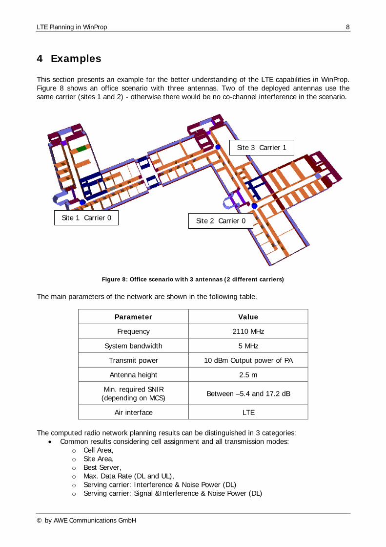
4 Examples This section presents an example for the better understanding of the LTE capabilities in WinProp. Figure 8 shows an office scenario with three antennas. Two of the deployed antennas use the same carrier (sites 1 and 2) - otherwise there would be no co-channel interference in the scenario.
Site 3 Carrier 1
Site 1 Carrier 0 Site 2 Carrier 0
Figure 8: Office scenario with 3 antennas (2 different carriers) The main parameters of the network are shown in the following table.
Parameter Value
Frequency 2110 MHz
System bandwidth 5 MHz
Transmit power 10 dBm Output power of PA
Antenna height 2.5 m
Min. required SNIR (depending on MCS) Between –5.4 and 17.2 dB
Air interface LTE
The computed radio network planning results can be distinguished in 3 categories:
• Common results considering cell assignment and all transmission modes: o Cell Area, o Site Area, o Best Server, o Max. Data Rate (DL and UL), o Serving carrier: Interference & Noise Power (DL) o Serving carrier: Signal &Interference & Noise Power (DL)
© by AWE Communications GmbH

LTE Planning in WinProp 9
• Cell Assignment: o Received Power o Received Sites o Received Cells o Received Carriers o Max SNIR (DL)
• For each transmission mode: o DL: Min Tx Power BS how much BS power is required to reach reception level o DL: Max Rx Power MS how much MS power is received on max. (full power BS) o DL: Max SNIR which SNIR is received on maximum (full power BS) o DL: Reception Probability o UL: Min Tx Power MS how much MS power is required to reach reception level o UL: Max Rx Power BS how much BS power is received on max. (full power MS) o UL: Max SNIR which SNIR is received on maximum (full power MS)
Accordingly the result maps consider two different settings on the transmitting side. Either Min. required power on the transmitter in order to reach the reception level (i.e. incl. power control) for the “Min Tx Power BS” and the “Min Tx Power MS” maps or full power transmission (i.e. without power control) for all the other maps. Figures 9-11 show the max. data rate map evaluating all transmission modes and the site area map and best server map for this network configuration. Here the influence of the carrier assignment is clearly visible. The two antennas operating on carrier 0 are interfering each other (assumed load of 100%) while the site 3 on carrier 1 has less interference and provides therefore a higher throughout in the corresponding cell area. As the cell assignment is based on the highest received power in downlink (DL) the throughout is limited in the region where the signals from site 1 and site 2 arrive with similar levels (South of site 1). Here the interference limits the SNIR.
Figure 9: Max. data rate (DL) for indoor network
© by AWE Communications GmbH

LTE Planning in WinProp 10
Figure 10: Site Area map for indoor network
Figure 11: Best Server map for indoor network
Figures 12 and 13 show two result maps from the cell assignment, first the received power map and then the max. SNIR map. While the received power map is influenced by the location of the sites and the propagation condition, the SNIR map is clearly influenced by the carrier assignment.
© by AWE Communications GmbH

LTE Planning in WinProp 11
Despite there are high received powers around sites 1 and 2, the SNIR is limited due to the frequency reuse (same carrier).
Figure 12: Received power (DL) in cell assignment
Figure 13: Max. SNIR (DL) map in cell assignment
© by AWE Communications GmbH

LTE Planning in WinProp 12
Figures 14 and 15 show two result maps for an individual transmission mode, first the min. required BS power map and then the max. SNIR map.
Figure 14: Min. required BS power map for transmission mode
Figure 15: Max. SNIR map for transmission mode
© by AWE Communications GmbH

LTE Planning in WinProp 13
In order to show the impact on the load (assumed percentage of mean Tx power in downlink for the neighboring cells) the Figure 16 shows the improved max. SNIR map (same transmission mode as on Figure 14) and the Figure 17 indicates the improved throughput due to the reduced load.
Figure 16: Max. SNIR map for transmission mode (30% load)
Figure 17: Max. data rate (DL) for indoor network (30% load)
© by AWE Communications GmbH

LTE Planning in WinProp 14
The following Figures show an example for an urban LTE deployment. The Figure 18 shows the received power in cell assignment for the deployed six 3-sector sites.
Figure 18: Received power (DL) in cell assignment for urban network
In the Figure 19 the max. available data rate (throughput) for the urban network is shown assuming a load of 30%. In the main beams of the individual sectors the max. data rate is available depending on the interference situation.
© by AWE Communications GmbH

LTE Planning in WinProp 15
Figure 19: Max. data rate (DL) for urban network (30% load)
© by AWE Communications GmbH