network layer 4-1 chapter 4 network layer (part ii) scsc512
TRANSCRIPT
Network Layer 4-1
Chapter 4Network Layer(Part II)
SCSC512
Network Layer 4-2
Chapter 4: Network Layer
4. 1 Introduction4.2 Virtual circuit and
datagram networks4.3 What’s inside a
router4.4 IP: Internet Protocol
Datagram format IPv4 addressing ICMP IPv6
4.5 Routing algorithms Link state Distance Vector Hierarchical routing
4.6 Routing in the Internet RIP OSPF BGP
4.7 Broadcast and multicast routing

Network Layer 4-3
1
23
0111
value in arrivingpacket’s header
routing algorithm
local forwarding tableheader value output link
0100010101111001
3221
Interplay between routing, forwarding

Network Layer 4-4
u
yx
wv
z2
2
13
1
1
2
53
5
Graph: G = (N,E)
N = set of routers = { u, v, w, x, y, z }
E = set of links ={ (u,v), (u,x), (v,x), (v,w), (x,w), (x,y), (w,y), (w,z), (y,z) }
Graph abstraction
Remark: Graph abstraction is useful in other network contexts
Example: P2P, where N is set of peers and E is set of TCP connections

Network Layer 4-5
Graph abstraction: costs
u
yx
wv
z2
2
13
1
1
2
53
5 • c(x,x’) = cost of link (x,x’)
- e.g., c(w,z) = 5
• cost could always be 1, or inversely related to bandwidth,or inversely related to congestion
Cost of path (x1, x2, x3,…, xp) = c(x1,x2) + c(x2,x3) + … + c(xp-1,xp)
Question: What’s the least-cost path between u and z ?
Routing algorithm: algorithm that finds least-cost path

Network Layer 4-6
Routing Algorithm classification
A. Global or decentralized?
Global: all routers have complete
topology, link cost info “link state” algorithmsDecentralized: router knows physically-
connected neighbors, link costs to neighbors
iterative process of computation, exchange of info with neighbors
“distance vector” algorithms
B.Static or dynamic?Static: routes change slowly
over timeDynamic: routes change more
quickly periodic update in response to link
cost changes

Routing Algorithm classification Load sensitive vs. Load insensitive
Link costs vary dynamically or not• If so, a routing algorithm will tend to choose
routes around a congested link
Example: ARPAnet, Internet routing protocols (RIP, OSPF, BGP)
Network Layer 4-7
Network Layer 4-8
Chapter 4: Network Layer
4. 1 Introduction4.2 Virtual circuit and
datagram networks4.3 What’s inside a
router4.4 IP: Internet Protocol
Datagram format IPv4 addressing ICMP IPv6
4.5 Routing algorithms Link state Distance Vector Hierarchical routing
4.6 Routing in the Internet RIP OSPF BGP
4.7 Broadcast and multicast routing
Network Layer 4-9
A Link-State Routing Algorithm
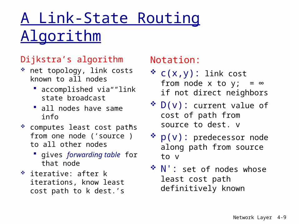
Dijkstra’s algorithm net topology, link costs
known to all nodes accomplished via “link
state broadcast” all nodes have same
info computes least cost paths
from one node (‘source”) to all other nodes gives forwarding table
for that node iterative: after k iterations,
know least cost path to k dest.’s
Notation: c(x,y): link cost from
node x to y; = ∞ if not direct neighbors
D(v): current value of cost of path from source to dest. v
p(v): predecessor node along path from source to v
N': set of nodes whose least cost path definitively known
Network Layer 4-10
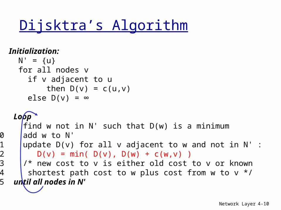
Dijsktra’s Algorithm
1 Initialization: 2 N' = {u} 3 for all nodes v 4 if v adjacent to u 5 then D(v) = c(u,v) 6 else D(v) = ∞ 7 8 Loop 9 find w not in N' such that D(w) is a minimum 10 add w to N' 11 update D(v) for all v adjacent to w and not in N' : 12 D(v) = min( D(v), D(w) + c(w,v) ) 13 /* new cost to v is either old cost to v or known 14 shortest path cost to w plus cost from w to v */ 15 until all nodes in N'
Network Layer 4-11
w3
4
v
x
u
5
37 4
y
8
z2
7
9
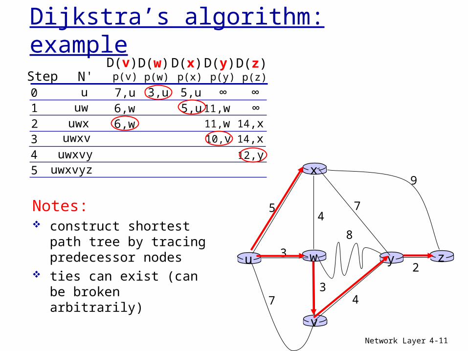
Dijkstra’s algorithm: example
Step N'D(v)
p(v)
012345
D(w)p(w)
D(x)p(x)
D(y)p(y)
D(z)p(z)
u ∞ ∞ 7,u 3,u 5,uuw ∞ 11,w 6,w 5,u
14,x 11,w 6,wuwxuwxv 14,x 10,v
uwxvy 12,y
Notes: construct shortest path
tree by tracing predecessor nodes
ties can exist (can be broken arbitrarily)
uwxvyz
Network Layer 4-12
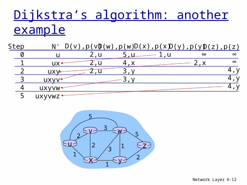
Dijkstra’s algorithm: another example
Step012345
N'u
uxuxy
uxyvuxyvw
uxyvwz
D(v),p(v)2,u2,u2,u
D(w),p(w)5,u4,x3,y3,y
D(x),p(x)1,u
D(y),p(y)∞
2,x
D(z),p(z)∞ ∞
4,y4,y4,y
u
yx
wv
z2
2
13
1
1
2
53
5

Network Layer 4-13
Dijkstra’s algorithm: example (2)
u
yx
wv
z
Resulting shortest-path tree from u:
vx
y
w
z
(u,v)(u,x)
(u,x)
(u,x)
(u,x)
destination link
Resulting forwarding table in u:

Network Layer 4-14
Dijkstra’s algorithm, discussion
Algorithm complexity: n nodes each iteration: need to check all nodes, w, not in N n(n+1)/2 comparisons: O(n2) more efficient implementations possible: O(nlogn)
Oscillations possible: e.g., link cost = amount of carried traffic
A
D
C
B1 1+e
e0
e
1 1
0 0
A
D
C
B2+e 0
001+e1
A
D
C
B0 2+e
1+e10 0
A
D
C
B2+e 0
e01+e1
initially… recompute
routing… recompute … recompute

Network Layer 4-15
Chapter 4: Network Layer
4. 1 Introduction4.2 Virtual circuit and
datagram networks4.3 What’s inside a
router4.4 IP: Internet Protocol
Datagram format IPv4 addressing ICMP IPv6
4.5 Routing algorithms Link state Distance Vector Hierarchical routing
4.6 Routing in the Internet RIP OSPF BGP
4.7 Broadcast and multicast routing

Network Layer 4-16
Distance Vector Algorithm
Bellman-Ford Equation (dynamic programming)
Definedx(y) := cost of least-cost path from x to y
Then
dx(y) = min {c(x,v) + dv(y) }
where min is taken over all neighbors v of x
v

Network Layer 4-17
Bellman-Ford example
u
yx
wv
z2
2
13
1
1
2
53
5Clearly, dv(z) = 5, dx(z) = 3, dw(z) = 3
du(z) = min { c(u,v) + dv(z), c(u,x) + dx(z), c(u,w) + dw(z) } = min {2 + 5, 1 + 3, 5 + 3} = 4
Node that achieves minimum is nexthop in shortest path ➜ forwarding table
B-F equation says:
Network Layer 4-18
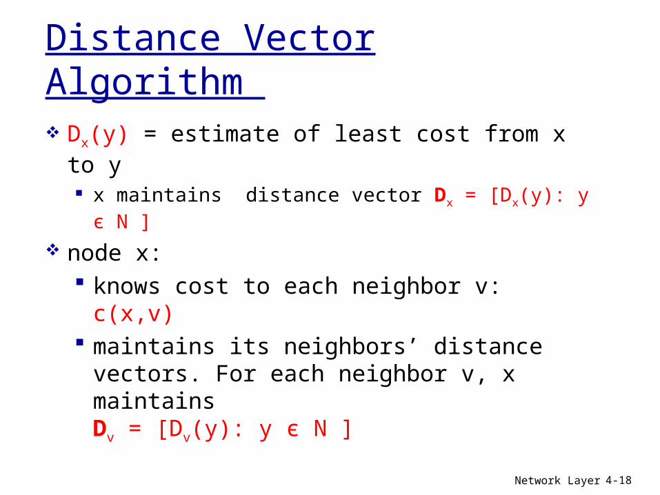
Distance Vector Algorithm
Dx(y) = estimate of least cost from x to y x maintains distance vector Dx = [Dx(y): y є
N ] node x:
knows cost to each neighbor v: c(x,v) maintains its neighbors’ distance
vectors. For each neighbor v, x maintains Dv = [Dv(y): y є N ]

Network Layer 4-19
Distance vector algorithm (4)
Basic idea: from time-to-time, each node sends its own
distance vector estimate to neighbors when x receives new DV estimate from
neighbor, it updates its own DV using B-F equation:Dx(y) ← minv{c(x,v) + Dv(y)} for each node y ∊ N
under minor, natural conditions, the estimate Dx(y) converge to the actual least cost dx(y)

Network Layer 4-20
Distance Vector Algorithm (5)
Iterative, asynchronous: each local iteration caused by:
local link cost change DV update message from
neighbor
Distributed: each node notifies
neighbors only when its DV changes neighbors then notify
their neighbors if necessary
wait for (change in local link cost or msg from neighbor)
recompute estimates
if DV to any dest has
changed, notify neighbors
Each node:

Network Layer 4-21
x y z
xyz
0 2 7
∞ ∞ ∞∞ ∞ ∞
from
cost to
from
from
x y z
xyz
0
from
cost to
x y z
xyz
∞ ∞
∞ ∞ ∞
cost to
x y z
xyz
∞ ∞ ∞7 1 0
cost to
∞2 0 1
∞ ∞ ∞
2 0 17 1 0
time
x z12
7
y
node x table
node y table
node z table
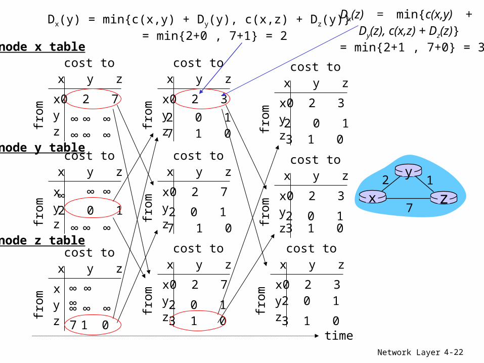
Dx(y) = min{c(x,y) + Dy(y), c(x,z) + Dz(y)} = min{2+0 , 7+1} = 2
Dx(z) = min{c(x,y) +
Dy(z), c(x,z) + Dz(z)}
= min{2+1 , 7+0} = 3
32
Network Layer 4-22
x y z
xyz
0 2 7
∞ ∞ ∞∞ ∞ ∞
from
cost to
from
from
x y z
xyz
0 2 3
from
cost tox y z
xyz
0 2 3
from
cost to
x y z
xyz
∞ ∞
∞ ∞ ∞
cost tox y z
xyz
0 2 7
from
cost to
x y z
xyz
0 2 3
from
cost to
x y z
xyz
0 2 3
from
cost tox y z
xyz
0 2 7
from
cost to
x y z
xyz
∞ ∞ ∞7 1 0
cost to
∞2 0 1
∞ ∞ ∞
2 0 17 1 0
2 0 17 1 0
2 0 13 1 0
2 0 13 1 0
2 0 1
3 1 0
2 0 1
3 1 0
time
x z12
7
y
node x table
node y table
node z table
Dx(y) = min{c(x,y) + Dy(y), c(x,z) + Dz(y)} = min{2+0 , 7+1} = 2
Dx(z) = min{c(x,y) + Dy(z), c(x,z) + Dz(z)} = min{2+1 , 7+0} = 3
Network Layer 4-23
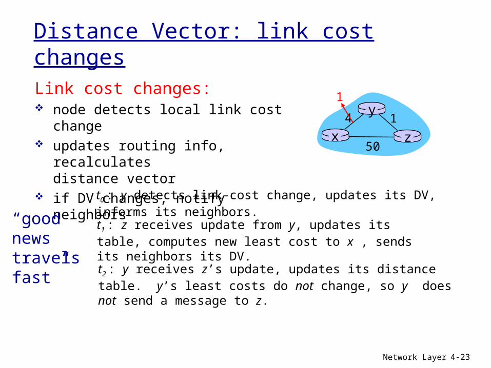
Distance Vector: link cost changes
Link cost changes: node detects local link cost
change updates routing info, recalculates
distance vector if DV changes, notify neighbors
“goodnews travelsfast”
x z14
50
y1
t0 : y detects link-cost change, updates its DV, informs its neighbors.t1 : z receives update from y, updates its table, computes new least cost to x , sends its neighbors its DV.t2 : y receives z’s update, updates its distance table. y’s least costs do not change, so y does not send a message to z.
Network Layer 4-24
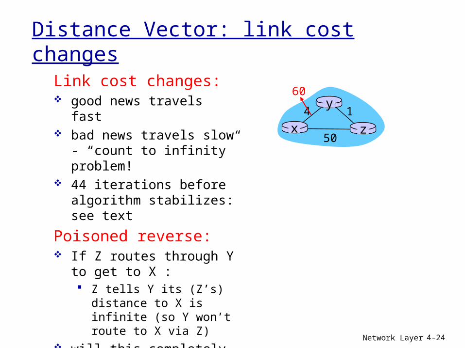
Distance Vector: link cost changes
Link cost changes: good news travels fast bad news travels slow -
“count to infinity” problem!
44 iterations before algorithm stabilizes: see text
Poisoned reverse: If Z routes through Y to
get to X : Z tells Y its (Z’s)
distance to X is infinite (so Y won’t route to X via Z)
will this completely solve count to infinity problem?
x z14
50
y60

Network Layer 4-25
Comparison of LS and DV algorithms
Message complexity LS: with n nodes, E links,
O(nE) msgs sent DV: exchange between
neighbors only convergence time varies
Speed of Convergence LS: O(n2) algorithm requires
O(nE) msgs may have oscillations
DV: convergence time varies may be routing loops count-to-infinity problem
Robustness: what happens if router malfunctions?
LS: node can advertise
incorrect link cost each node computes only
its own table
DV: DV node can advertise
incorrect path cost each node’s table used by
others • error propagate thru
network

Network Layer 4-26
Chapter 4: Network Layer
4. 1 Introduction4.2 Virtual circuit and
datagram networks4.3 What’s inside a
router4.4 IP: Internet Protocol
Datagram format IPv4 addressing ICMP IPv6
4.5 Routing algorithms Link state Distance Vector Hierarchical routing
4.6 Routing in the Internet RIP OSPF BGP
4.7 Broadcast and multicast routing

Network Layer 4-27
Hierarchical Routing
scale: with 200 million destinations:
can’t store all dest’s in routing tables!
routing table exchange would swamp links!
administrative autonomy
internet = network of networks
each network admin may want to control routing in its own network
Our routing study thus far - idealization all routers identical network “flat”… not true in practice

Network Layer 4-28
Hierarchical Routing
aggregate routers into regions, “autonomous systems” (AS)
routers in same AS run same routing protocol “intra-AS” routing
protocol routers in different AS
can run different intra-AS routing protocol
gateway router at “edge” of its own
AS has link to router in
another AS

Network Layer 4-29
3b
1d
3a
1c2aAS3
AS1
AS21a
2c2b
1b
Intra-ASRouting algorithm
Inter-ASRouting algorithm
Forwardingtable
3c
Interconnected ASes
forwarding table configured by both intra- and inter-AS routing algorithm intra-AS sets entries
for internal dests inter-AS & intra-As
sets entries for external dests

Network Layer 4-30
Inter-AS tasks suppose router in
AS1 receives datagram destined outside of AS1: router should
forward packet to gateway router, but which one?
AS1 must:1. learn which dests
are reachable through AS2, which through AS3
2. propagate this reachability info to all routers in AS1
job of inter-AS routing!
AS3
AS2
3b
3c
3a
AS1
1c1a
1d1b
2a2c
2b
othernetworks
othernetworks

Network Layer 4-31
Example: Setting forwarding table in router 1d suppose AS1 learns (via inter-AS protocol) that
subnet x reachable via AS3 (gateway 1c) but not via AS2. inter-AS protocol propagates reachability info to all internal
routers router 1d determines from intra-AS routing info that
its interface I is on the least cost path to 1c. installs forwarding table entry (x,I)
AS3
AS2
3b
3c
3a
AS1
1c1a
1d1b
2a2c
2b
othernetworks
othernetworks
x…

Network Layer 4-32
Example: Choosing among multiple ASes
now suppose AS1 learns from inter-AS protocol that subnet x is reachable from AS3 and from AS2.
to configure forwarding table, router 1d must determine which gateway it should forward packets towards for dest x this is also job of inter-AS routing protocol!
AS3
AS2
3b
3c
3a
AS1
1c1a
1d1b
2a2c
2b
othernetworks
othernetworks
x ……
…
?

Network Layer 4-33
Learn from inter-AS protocol that subnet x is reachable via multiple gateways
Use routing infofrom intra-AS
protocol to determine
costs of least-cost paths to each
of the gateways
Hot potato routing:Choose the
gatewaythat has the
smallest least cost
Determine fromforwarding table the interface I that leads
to least-cost gateway. Enter (x,I) in
forwarding table
Example: Choosing among multiple ASes
now suppose AS1 learns from inter-AS protocol that subnet x is reachable from AS3 and from AS2.
to configure forwarding table, router 1d must determine towards which gateway it should forward packets for dest x. this is also job of inter-AS routing protocol!
hot potato routing: send packet towards closest of two routers.

Network Layer 4-34
Chapter 4: Network Layer
4. 1 Introduction4.2 Virtual circuit and
datagram networks4.3 What’s inside a
router4.4 IP: Internet Protocol
Datagram format IPv4 addressing ICMP IPv6
4.5 Routing algorithms Link state Distance Vector Hierarchical routing
4.6 Routing in the Internet RIP OSPF BGP
4.7 Broadcast and multicast routing

Network Layer 4-35
Intra-AS Routing
also known as Interior Gateway Protocols (IGP) most common Intra-AS routing protocols:
RIP: Routing Information Protocol
OSPF: Open Shortest Path First
IGRP: Interior Gateway Routing Protocol (Cisco proprietary)
Network Layer 4-36
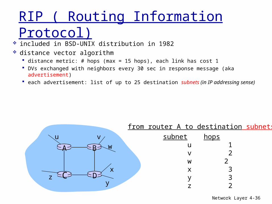
RIP ( Routing Information Protocol) included in BSD-UNIX distribution in 1982 distance vector algorithm
distance metric: # hops (max = 15 hops), each link has cost 1 DVs exchanged with neighbors every 30 sec in response message (aka
advertisement) each advertisement: list of up to 25 destination subnets (in IP addressing sense)
DC
BA
u vw
x
yz
subnet hops u 1 v 2 w 2 x 3 y 3 z 2
from router A to destination subnets:

Network Layer 4-37
RIP: Example
destination subnet next router # hops to dest
w A 2y B 2
z B 7x -- 1…. …. ....
routing table in router D
w x yz
A
C
D B

Network Layer 4-38
RIP: Example
destination subnet next router # hops to dest
w A 2y B 2
z B 7x -- 1…. …. ....
routing table in router D
w x yz
A
C
D B
A 5
dest next hops w - 1 x - 1 z C 4 …. … ...
A-to-D advertisement

Network Layer 4-39
RIP: Link Failure and Recovery If no advertisement heard after 180 sec -->
neighbor/link declared dead routes via neighbor invalidated new advertisements sent to neighbors neighbors in turn send out new advertisements
(if tables changed) link failure info quickly (?) propagates to entire
net poison reverse used to prevent ping-pong
loops (infinite distance = 16 hops)
Network Layer 4-40
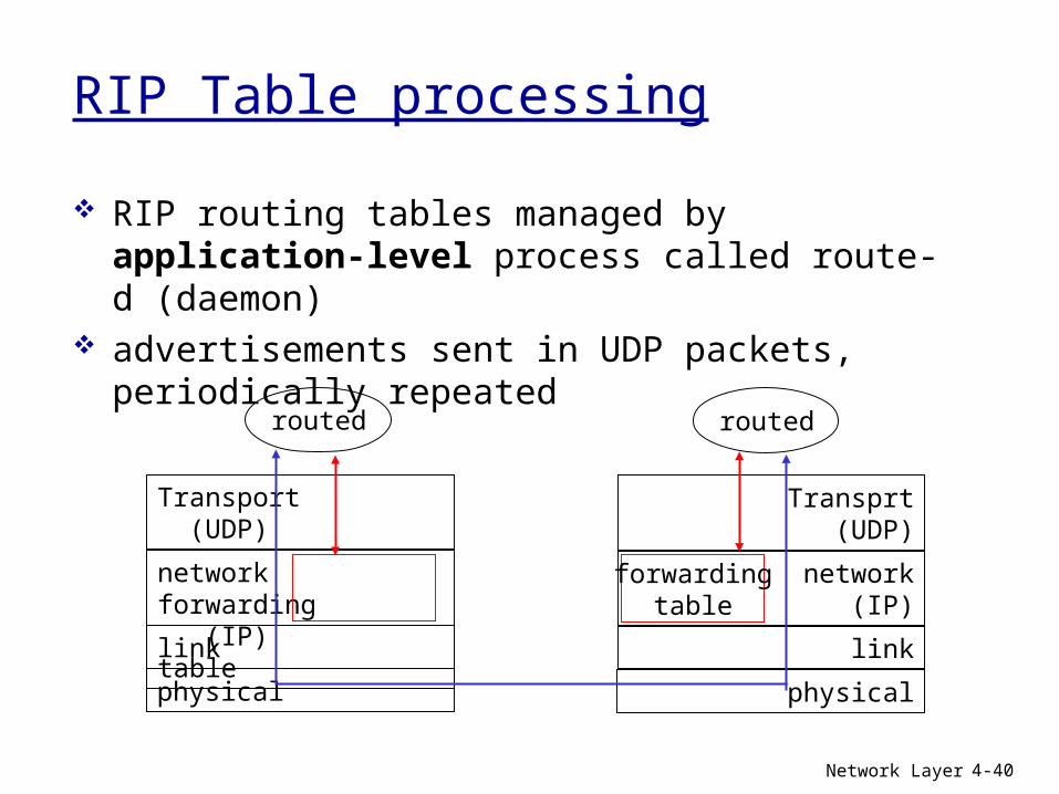
RIP Table processing
RIP routing tables managed by application-level process called route-d (daemon)
advertisements sent in UDP packets, periodically repeated
physical
link
network forwarding (IP) table
Transport (UDP)
routed
physical
link
network (IP)
Transprt (UDP)
routed
forwardingtable
Network Layer 4-41
OSPF (Open Shortest Path First)
“open”: publicly available uses Link State algorithm
LS packet dissemination topology map at each node route computation using Dijkstra’s algorithm
OSPF advertisement carries one entry per neighbor router
advertisements disseminated to entire AS (via flooding) carried in OSPF messages directly over IP (rather than
TCP or UDP

Network Layer 4-42
OSPF “advanced” features (not in RIP) security: all OSPF messages authenticated (to
prevent malicious intrusion) multiple same-cost paths allowed (only one path
in RIP) for each link, multiple cost metrics for different
TOS (e.g., satellite link cost set “low” for best effort ToS; high for real time ToS)
integrated uni- and multicast support: Multicast OSPF (MOSPF) uses same topology
data base as OSPF hierarchical OSPF in large domains.

Network Layer 4-43
Hierarchical OSPFboundary router
backbone router
Area 1
Area 2
Area 3
backbone
areaborderrouters
internalrouters
Network Layer 4-44
Hierarchical OSPF
two-level hierarchy: local area, backbone. link-state advertisements only in area each nodes has detailed area topology; only know
direction (shortest path) to nets in other areas. area border routers: “summarize” distances to nets
in own area, advertise to other Area Border routers. backbone routers: run OSPF routing limited to
backbone. boundary routers: connect to other AS’s.

Network Layer 4-45
Internet inter-AS routing: BGP
BGP (Border Gateway Protocol): the de facto inter-domain routing protocol “glue that holds the Internet together”
BGP provides each AS a means to: eBGP: obtain subnet reachability information from
neighboring ASs. iBGP: propagate reachability information to all AS-
internal routers. determine “good” routes to other networks based on
reachability information and policy. allows subnet to advertise its existence to rest
of Internet: “I am here”

Network Layer 4-46
BGP basics
when AS3 advertises a prefix to AS1: AS3 promises it will forward datagrams towards that prefix AS3 can aggregate prefixes in its advertisement
AS3
AS2
3b
3c
3a
AS1
1c1a
1d1b
2a2c
2b
othernetworks
othernetworks
BGP session: two BGP routers (“peers”) exchange BGP messages: advertising paths to different destination network prefixes
(“path vector” protocol) exchanged over semi-permanent TCP connections
BGP message

Network Layer 4-47
BGP basics: distributing path information
AS3
AS2
3b3a
AS1
1c1a
1d1b
2a2c
2b
othernetworks
othernetworks
using eBGP session between 3a and 1c, AS3 sends prefix reachability info to AS1. 1c can then use iBGP do distribute new prefix info to all
routers in AS1 1b can then re-advertise new reachability info to AS2 over
1b-to-2a eBGP session when router learns of new prefix, it creates entry for
prefix in its forwarding table.
eBGP session
iBGP session
Network Layer 4-48
Path attributes & BGP routes
advertised prefix includes BGP attributes prefix + attributes = “route”
two important attributes: AS-PATH: contains ASs through which prefix
advertisement has passed: e.g., AS 67, AS 17 NEXT-HOP: indicates specific internal-AS router to next-
hop AS. (may be multiple links from current AS to next-hop-AS)
gateway router receiving route advertisement uses import policy to accept/decline e.g., never route through AS x policy-based routing
Network Layer 4-49
BGP route selection
router may learn about more than 1 route to destination AS, selects route based on:1. local preference value attribute: policy
decision2. shortest AS-PATH 3. closest NEXT-HOP router: hot potato
routing4. additional criteria

Network Layer 4-50
BGP messages
BGP messages exchanged between peers over TCP connection
BGP messages: OPEN: opens TCP connection to peer and
authenticates sender UPDATE: advertises new path (or withdraws
old) KEEPALIVE: keeps connection alive in absence
of UPDATES; also ACKs OPEN request NOTIFICATION: reports errors in previous msg;
also used to close connection
Network Layer 4-51
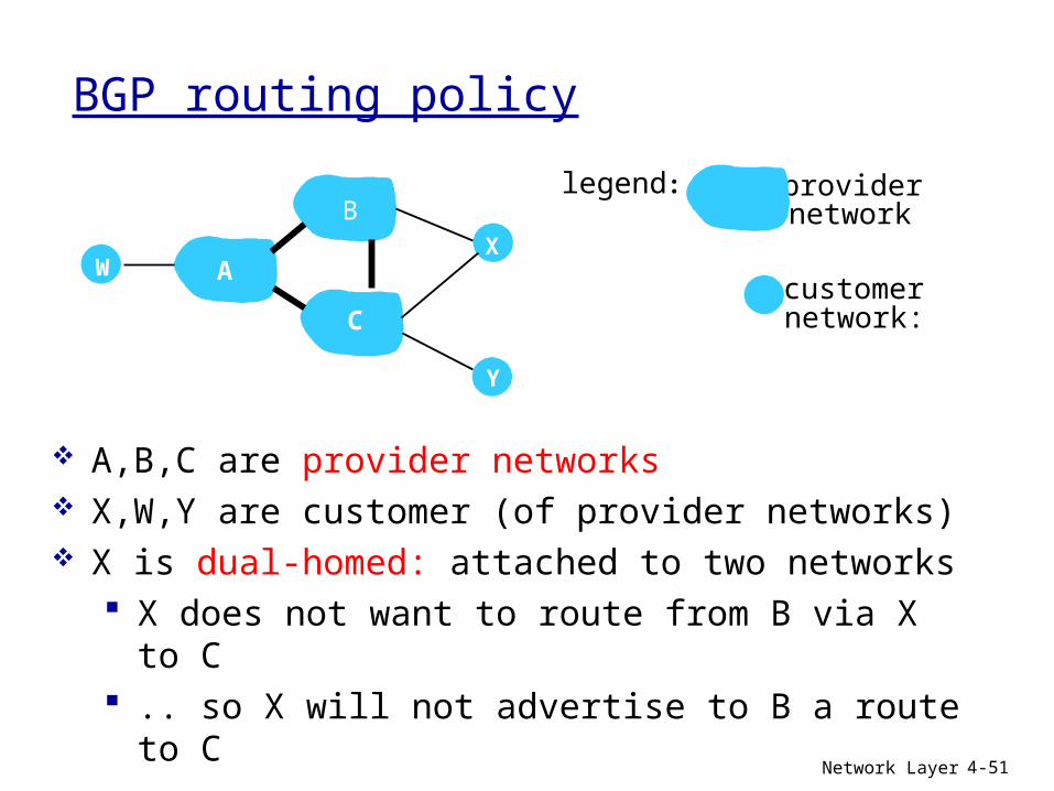
BGP routing policy
A,B,C are provider networks X,W,Y are customer (of provider networks) X is dual-homed: attached to two networks
X does not want to route from B via X to C .. so X will not advertise to B a route to C
A
B
C
W X
Y
legend:
customer network:
provider network

Network Layer 4-52
BGP routing policy (2)
A advertises path AW to B B advertises path BAW to X Should B advertise path BAW to C?
No way! B gets no “revenue” for routing CBAW since neither W nor C are B’s customers
B wants to force C to route to w via A B wants to route only to/from its customers!
A
B
C
W X
Y
legend:
customer network:
provider network
Network Layer 4-53
Why different Intra- and Inter-AS routing ?
Policy: Inter-AS: admin wants control over how its traffic
routed, who routes through its net. Intra-AS: single admin, so no policy decisions
needed
Scale: hierarchical routing saves table size, reduced
update trafficPerformance: Intra-AS: can focus on performance Inter-AS: policy may dominate over performance

Network Layer 4-54
Chapter 4: Network Layer
4. 1 Introduction4.2 Virtual circuit and
datagram networks4.3 What’s inside a
router4.4 IP: Internet Protocol
Datagram format IPv4 addressing ICMP IPv6
4.5 Routing algorithms Link state Distance Vector Hierarchical routing
4.6 Routing in the Internet RIP OSPF BGP
4.7 Broadcast and multicast routing

Network Layer 4-55
R1
R2
R3 R4
sourceduplication
R1
R2
R3 R4
in-networkduplication
duplicatecreation/transmissionduplicate
duplicate
Broadcast Routing deliver packets from source to all other nodes source duplication is inefficient:
source duplication: how does source determine recipient addresses?

Network Layer 4-56
In-network duplication
flooding: when node receives broadcast packet, sends copy to all neighbors problems: cycles & broadcast storm
controlled flooding: node only broqdcqsts pkt if it hasn’t broadcst same packet before node keeps track of packet ids already
broadacsted or reverse path forwarding (RPF): only
forward packet if it arrived on shortest path between node and source
spanning tree No redundant packets received by any node

Network Layer 4-57
A
B
G
DE
c
F
A
B
G
DE
c
F
(a) Broadcast initiated at A (b) Broadcast initiated at D
Spanning Tree
First construct a spanning tree Nodes forward copies only along
spanning tree
Network Layer 4-58
A
B
G
DE
c
F1
2
3
4
5
(a) Stepwise construction of spanning tree
A
B
G
DE
c
F
(b) Constructed spanning tree
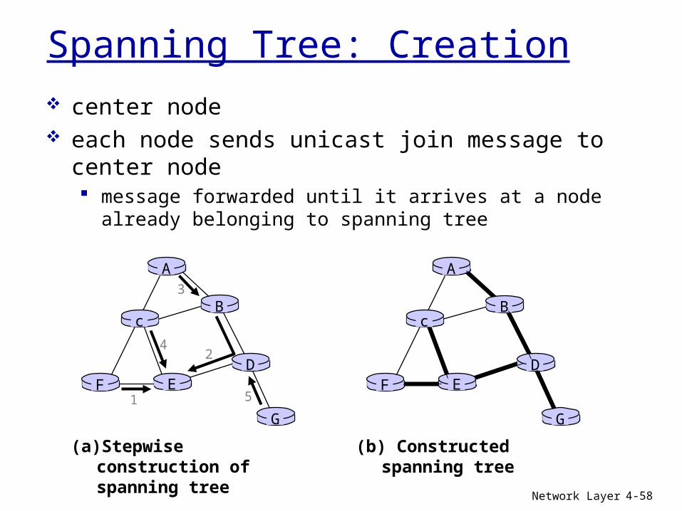
Spanning Tree: Creation center node each node sends unicast join message to
center node message forwarded until it arrives at a node already
belonging to spanning tree
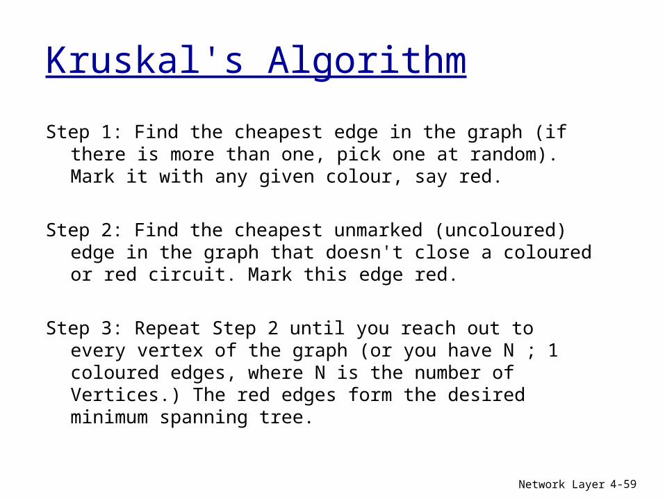
Kruskal's Algorithm
Step 1: Find the cheapest edge in the graph (if there is more than one, pick one at random). Mark it with any given colour, say red.
Step 2: Find the cheapest unmarked (uncoloured) edge in the graph that doesn't close a coloured or red circuit. Mark this edge red.
Step 3: Repeat Step 2 until you reach out to every vertex of the graph (or you have N ; 1 coloured edges, where N is the number of Vertices.) The red edges form the desired minimum spanning tree.
Network Layer 4-59

Prim's AlgorithmStep 0: Pick any vertex as a starting vertex. (Call it S).
Mark it with any given colour, say red. Step 1: Find the nearest neighbour of S (call it P1). Mark
both P1 and the edge SP1 red. Step 2: Find the nearest uncoloured neighbour to the red
subgraph (i.e., the closest vertex to any red vertex). Mark it and the edge connecting the vertex to the red subgraph in red.
Step 3: Repeat Step 2 until all vertices are marked red.
The red subgraph is a minimum spanning tree.
Network Layer 4-60

Multicast Routing: Problem Statement Goal: find a tree (or trees) connecting
routers having local mcast group members tree: not all paths between routers used source-based: different tree from each sender to rcvrs Group shared-tree: same tree used by all group
members
Group Shared tree Source-based trees
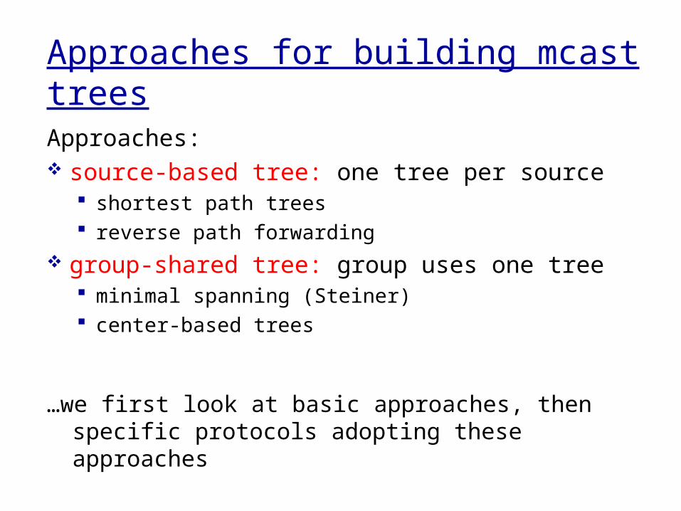
Approaches for building mcast treesApproaches: source-based tree: one tree per source
shortest path trees reverse path forwarding
group-shared tree: group uses one tree minimal spanning (Steiner) center-based trees
…we first look at basic approaches, then specific protocols adopting these approaches

Shortest Path Tree
mcast forwarding tree: tree of shortest path routes from source to all receivers Dijkstra’s algorithm
R1
R2
R3
R4
R5
R6 R7
21
6
3 4
5
i
router with attachedgroup member
router with no attachedgroup member
link used for forwarding,i indicates order linkadded by algorithm
LEGENDS: source

Reverse Path Forwarding
if (mcast datagram received on incoming link on shortest path back to center)
then flood datagram onto all outgoing links else ignore datagram
rely on router’s knowledge of unicast shortest path from it to sender
each router has simple forwarding behavior:
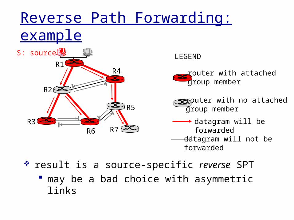
Reverse Path Forwarding: example
result is a source-specific reverse SPT may be a bad choice with asymmetric links
R1
R2
R3
R4
R5
R6 R7
router with attachedgroup member
router with no attachedgroup member
datagram will be forwarded
LEGENDS: source
datagram will not be forwarded

Reverse Path Forwarding: pruning forwarding tree contains subtrees with no mcast
group members no need to forward datagrams down subtree “prune” msgs sent upstream by router with
no downstream group members
R1
R2
R3
R4
R5
R6 R7
router with attachedgroup member
router with no attachedgroup member
prune message
LEGENDS: source
links with multicastforwarding
P
P
P

Shared-Tree: Steiner Tree
Steiner Tree: minimum cost tree connecting all routers with attached group members
problem is NP-complete excellent heuristics exists not used in practice:
computational complexity information about entire network needed monolithic: rerun whenever a router needs
to join/leave

Center-based trees
single delivery tree shared by all one router identified as “center” of tree to join:
edge router sends unicast join-msg addressed to center router
join-msg “processed” by intermediate routers and forwarded towards center
join-msg either hits existing tree branch for this center, or arrives at center
path taken by join-msg becomes new branch of tree for this router
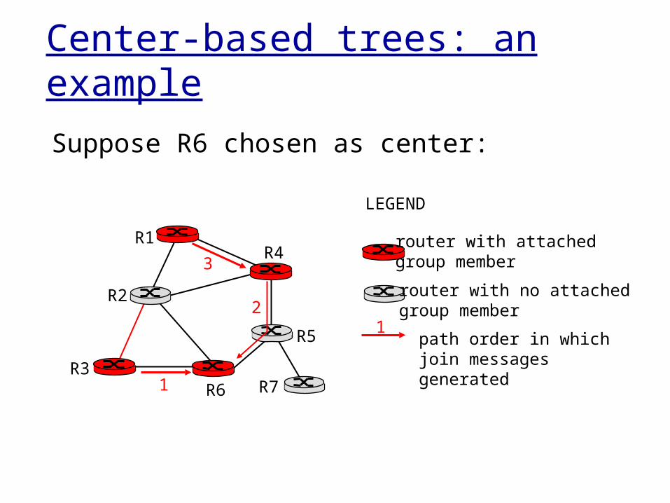
Center-based trees: an example
Suppose R6 chosen as center:
R1
R2
R3
R4
R5
R6 R7
router with attachedgroup member
router with no attachedgroup member
path order in which join messages generated
LEGEND
21
3
1
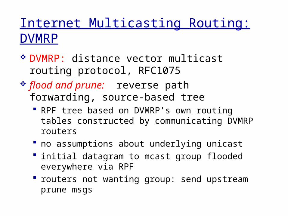
Internet Multicasting Routing: DVMRP
DVMRP: distance vector multicast routing protocol, RFC1075
flood and prune: reverse path forwarding, source-based tree RPF tree based on DVMRP’s own routing tables
constructed by communicating DVMRP routers no assumptions about underlying unicast initial datagram to mcast group flooded
everywhere via RPF routers not wanting group: send upstream
prune msgs

DVMRP: continued…
soft state: DVMRP router periodically (1 min.) “forgets” branches are pruned: mcast data again flows down unpruned branch downstream router: reprune or else continue
to receive data routers can quickly regraft to tree
following IGMP join at leaf odds and ends
commonly implemented in commercial routers Mbone routing done using DVMRP
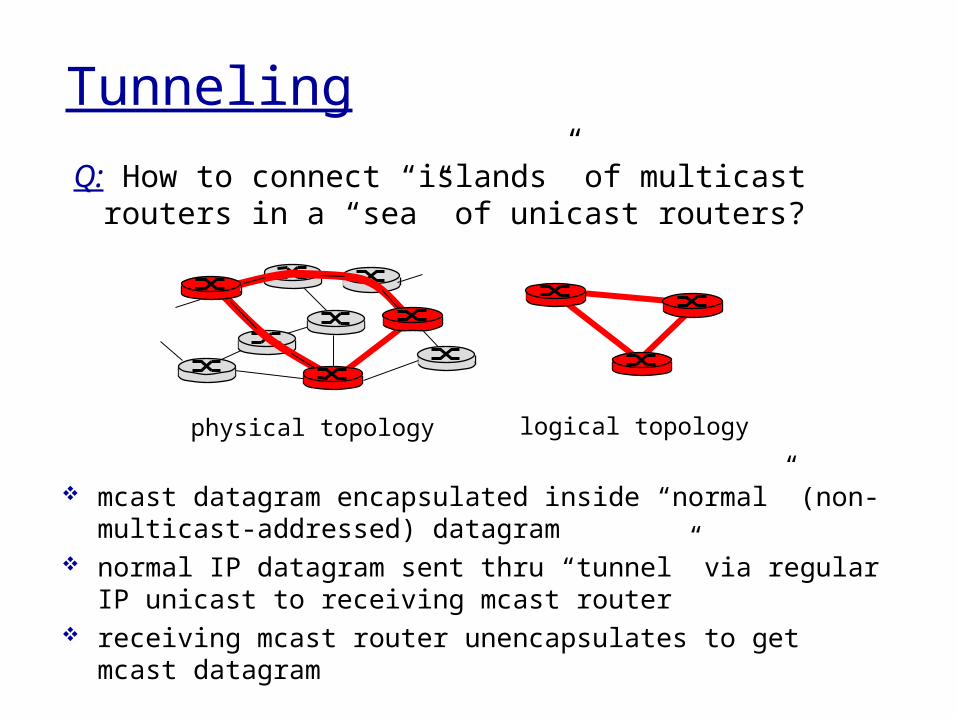
Tunneling
Q: How to connect “islands” of multicast routers in a “sea” of unicast routers?
mcast datagram encapsulated inside “normal” (non-multicast-addressed) datagram
normal IP datagram sent thru “tunnel” via regular IP unicast to receiving mcast router
receiving mcast router unencapsulates to get mcast datagram
physical topology logical topology
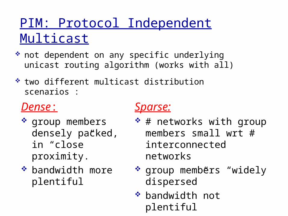
PIM: Protocol Independent Multicast
not dependent on any specific underlying unicast routing algorithm (works with all)
two different multicast distribution scenarios :
Dense: group members
densely packed, in “close” proximity.
bandwidth more plentiful
Sparse: # networks with group
members small wrt # interconnected networks
group members “widely dispersed”
bandwidth not plentiful

Consequences of Sparse-Dense Dichotomy: Dense group membership by
routers assumed until routers explicitly prune
data-driven construction on mcast tree (e.g., RPF)
bandwidth and non-group-router processing profligate
Sparse: no membership until
routers explicitly join receiver- driven
construction of mcast tree (e.g., center-based)
bandwidth and non-group-router processing conservative

PIM- Dense Mode
flood-and-prune RPF, similar to DVMRP but
underlying unicast protocol provides RPF info for incoming datagram
less complicated (less efficient) downstream flood than DVMRP reduces reliance on underlying routing algorithm
has protocol mechanism for router to detect it is a leaf-node router

PIM - Sparse Mode
center-based approach router sends join msg
to rendezvous point (RP) intermediate routers
update state and forward join
after joining via RP, router can switch to source-specific tree increased performance:
less concentration, shorter paths
R1
R2
R3
R4
R5
R6R7
join
join
join
all data multicastfrom rendezvouspoint
rendezvouspoint

PIM - Sparse Mode
sender(s): unicast data to RP,
which distributes down RP-rooted tree
RP can extend mcast tree upstream to source
RP can send stop msg if no attached receivers “no one is listening!”
R1
R2
R3
R4
R5
R6R7
join
join
join
all data multicastfrom rendezvouspoint
rendezvouspoint

Network Layer 4-78
Chapter 4: summary
4. 1 Introduction4.2 Virtual circuit and
datagram networks4.3 What’s inside a
router4.4 IP: Internet Protocol
Datagram format IPv4 addressing ICMP IPv6
4.5 Routing algorithms Link state Distance Vector Hierarchical routing
4.6 Routing in the Internet RIP OSPF BGP
4.7 Broadcast and multicast routing