network integration of ssresreschool.chania.teicrete.gr/lecture_notes/1_2_taylor1...network...
TRANSCRIPT
Small Scale Renewable Energy Sources and Energy Saving: 6 - 17th July 2009
Network Integration of Small-scale Renewable Energy Sources
Dr G A Taylor
Brunel Institute of Power SystemsBrunel University, London, UK
E-mail: [email protected]: www.brunel.ac.uk/~eesrgat

Network Integration of Small-scale Renewable Energy Sources
Overview• Introduction to UK Electricity Industry• Impact of electricity industry privatisation• Distribution networks• Classification of distributed generation• Deployment of Small-Scale Embedded
Generation (SSEG)
• ‘Overcoming Voltage Control Issues’ –Maciej Fila [4-5]
UK ELECTRICITY INDUSTRY
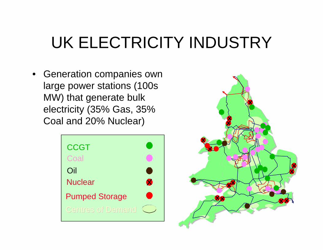
• Generation companies own large power stations (100s MW) that generate bulk electricity (35% Gas, 35% Coal and 20% Nuclear)
CCGTCoal
OilNuclear
Pumped Storage
Centres of DemandCentres of Demand
UK ELECTRICITY INDUSTRY
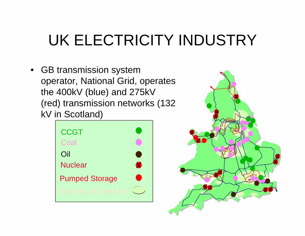
• GB transmission system operator, National Grid, operates the 400kV (blue) and 275kV (red) transmission networks (132 kV in Scotland)
CCGTCoal
OilNuclear
Pumped Storage
Centres of DemandCentres of Demand

UK ELECTRICITY INDUSTRY
• Distribution Network Operators (DNOs) manage 132kV to LV distribution networks in England & Wales (below 132 kV in Scotland)
• Electricity supply businesses sell electricity to customers anywhere within the UK
Targets for UK Energy Sector• Reduction in CO2 emmissions by 20% by
2010 and 60% by 2050• 20% electricity generated from renewables
by 2020• 2009 approximately 5-6 %• Diversity of electricity generation will be
required
UK ELECTRICITY INDUSTRY
ROLE OF UK REGULATOR
• Distribution networks are logical monopolies
• UK regulator ofgem conducts Distribution Price Control Reviews (DPCR) every five years
• The review – determines the revenue that a distribution network
operator can collect from customers – sets the amount of capital investment and allowable
rate of return– sets targets to reduce operational costs

ROLE OF UK REGULATOR
• Ofgem introduced new research and development incentives in DPCR4– Innovation Funding Incentive (IFI)– Registered Power Zones
• Ofgem consulting on Transmission Price Control Reviews
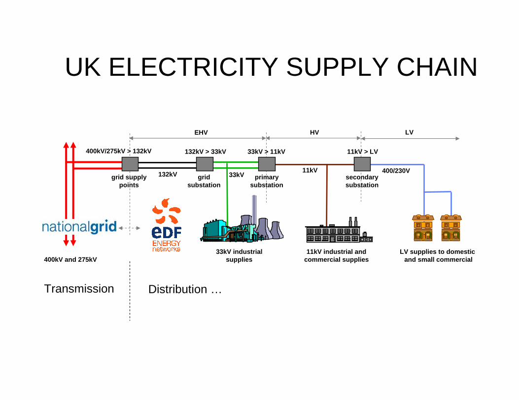
400kV and 275kV
400kV/275kV > 132kV
132kV 33kV11kV
33kV industrialsupplies
11kV industrial andcommercial supplies
LV supplies to domestic and small commercial
400/230Vsecondarysubstation
primarysubstation
33kV > 11kV 11kV > LV
gridsubstation
132kV > 33kV
grid supplypoints
EHV HV LV
UK ELECTRICITY SUPPLY CHAIN
Transmission Distribution …
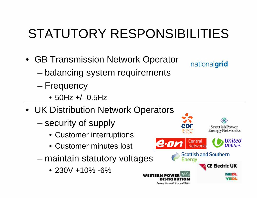
STATUTORY RESPONSIBILITIES
• GB Transmission Network Operator
– balancing system requirements– Frequency
• 50Hz +/- 0.5Hz
• UK Distribution Network Operators
– security of supply• Customer interruptions• Customer minutes lost
– maintain statutory voltages• 230V +10% -6%

DISTRIBUTION NETWORK ASSET MANAGEMENT
• Infrastructure planning– Strategic development of the 132kV and 33kV network
– Consider changing loads and generation
– Determining where new customer connections will be made
– Asset replacement requirements
DISTRIBUTION NETWORK ASSET MANAGEMENT
• Distribution planning– Development of the 11kV & Low Voltage (LV) network
– Determining where new customer connections will be made for larger loads and generation
• Asset optimisation and technology– Development of the asset strategy
– Life-cycle, maintenance and replacement strategies
– Optimum use of new technology?
– What equipment will be installed on the network?
CLASSIFICATION OF DISTRIBUTED GENERATION
Electricity Network Association (ENA) [1]
• Defines Engineering Recommendations for distributed generation
• G75/1, G59/1 and G83/1 recommendations for different classes of distributed generation
• Classification mainly based on generator real power output and network voltage
CLASSIFICATION OF DISTRIBUTED GENERATION
Engineering Recommendations
• G75/1: embedded (distributed) generation at or below 132 kV and generation does not exceed 50 MW– 30 or 10 MW in some UK areas ie Scotland
• G59/1: embedded (distributed) generation at or below 20 kV and generation does not exceed 5 MW
CLASSIFICATION OF DISTRIBUTION GENERATION
Engineering Recommendations
• G83/1: small scale embedded generation (SSEG) up to 16A per phase; typically up to 10 kW on LV networks (below 11 kV in the UK)
• ER G83/1 is an 'Annex 1 Standard‘, which is a UK electricity industry national standard that implements Distribution Code requirements
• Standard is listed in Annex 1 of the UK Distribution Code

CLASSIFICATION OF DISTRIBUTION GENERATION
Engineering Recommendations
• Provides technical requirements guidance for connection of SSEG in parallel with public LV distribution networks
• Consistent with Electricity, Safety, Quality and Continuity Regulations (ESQCR)
• Generic connection requirements for all types of SSEG:– Domestic (or Micro) Combined Heat Power (DCHP)
– Photovoltaic (PV)
– Fuel Cells, Micro wind and Micro Hydro
• Specific requirements for each different type of SSEG are also defined in the annexes
CLASSIFICATION OF DISTRIBUTION GENERATION
Engineering Recommendations
• G83/1 considers the following technical issues:– Power Quality
– Harmonic current emissions
– Voltage fluctuations and flicker
– DC injection / power factor
– Under/Over frequency switch off
– Under/Over Voltage switch off
– Loss of mains test
– Earthing arrangements
– Short circuit and fault current levels
DEPLOYMENT OF SSEG
As of July 2009
• In the UK current volume of SSEG or microgenerationconnected to distribution networks is very small (10s MW)
• Impact of SSEG on networks has not been a significant issue to date
• No clustering problems in existing networks as a result of customers choosing to install SSEG either as a new device or as a replacement of a previous heating system
• Emerging distribution network problems in Germany due to large deployment of PV SSEG

DEPLOYMENT OF SSEG
As of July 2009
• In the future UK local authorities may require developers to install smaller generators on new buildings in order to obtain planning consent
• For new housing developments that contain SSEG the network will be specifically designed to cater for the technical issues
• A scenario that could be challenging is high penetration of domestic CHP or PV on existing networks leading to reverse power flows during periods of low demand and high generation (eg week day mornings)
DEPLOYMENT OF SSEG
As of July 2009
• Existing LV distribution networks designed to cater for a unidirectional energy flow from the distribution substation to customer installations (radial or feeder networks)
• Connection of multiple SSEG units can have an adverse effect on network operation
DEPLOYMENT OF SSEG
As of July 2009
• Main issues that need to be considered include [2]:– Impact on voltage levels, both over and under-
voltage
– Short circuit and fault current levels
– System loading
– Voltage unbalance

DEPLOYMENT OF SSEG
Impact on voltage levels
• Overvoltage – SSEG export will tend to increase the voltage profile on
LV networks
– Under low load conditions
– Voltages at upper limit of the statutory voltage range
– Voltage level due the installation could increase above statutory limits leading to SSEG tripping or export constraints
DEPLOYMENT OF SSEG
Impact on voltage levels
• Undervoltage– Risk that transient disturbances on the HV system
could lead to voltage dips on LV system
– Resulting in widespread tripping of SSEG due to undervoltage protection
– Original disturbance compounded by sudden increase in demand as the system supports the load that was previously supplied by SSEG
DEPLOYMENT OF SSEG
Short circuit and fault current levels
• SSEG connection to LV networks may cause short circuit and fault current, from the source and the SSEG, to exceed short circuit or fault current rating of network equipment
• Short circuit or fault current contribution from SSEG must be considered to ensure that single and three phase fault duty imposed on Distribution Network Operator (DNO) and customer's equipment does not exceed equipment rating
• Contribution to short circuit and fault currents will depend upon specific SSEG technology
DEPLOYMENT OF SSEG
System loading
• Low voltage distribution networks have been designed assuming power flows from the substation out to the customers
• Radial or feeder design
• With large-scale deployment of SSEG the direction of power flows may reverse
• DNO may need to assess the magnitude and direction of power flow to ensure equipment thermal ratings are not exceeded

DEPLOYMENT OF SSEG
Voltage unbalance
• For large-scale deployment of single-phase SSEG units (eg housing estates), balancing the unit generation evenly against the load on the phases will need to be considered
• The connection of significant quantities of SSEG in LV networks could also have an adverse impact on the 11kV and higher voltage networks– Issues are similar to those for the low voltage network
– In particular, the impact of voltage changes and effect on the primary voltage control needs to be carefully considered
DEPLOYMENT OF SSEG
Future distribution network design
• It is important to note that the SSEG penetration level at which issues may appear depends upon specific SSEG and network characteristics [3]
• Across the UK there exists a range of distribution network designs and operating practices and thus the impact will vary accordingly
• Mitigation could take the form of more sophisticated control systems, plant and switchgear upgrade but network augmentation will often be required

DEPLOYMENT OF SSEGFuture distribution network design
• Realising full potential of LV networks could require revision of ESQCR that would permit a wider (LV) voltage operating range and hence enable large-scale deployment of SSEG into LV networks
• UK government support for demonstrator mixed SSEG based installations will provide much needed learning experiences for all stakeholders
• DNOs would benefit from practical real tests of appropriate scale where the effects of SSEG technologies can be properly planned for, assessed and tested

DEPLOYMENT OF SSEG
Connection of SSEG (up to 16A per phase)
• Procedures for connecting SSEG are fully described in the Engineering Recommendation G83/1 [2]
• Procedures are designed to facilitate connection SSEG whilst maintaining integrity of the public LV network, both in terms of safety and supply quality
DEPLOYMENT OF SSEGConnection of SSEG (up to 16A per phase)
• To comply with ESQCR Regulation 22 the Installer has to make the DNO aware of SSEG installation at or before the time of commissioning
• DNO may not refuse to accept the connection providing installation complies with the requirements of ESQCR Regulation 22
• However under the terms of ESQCR Regulation 26 the DNO may require a SSEG unit to be disconnected if it is a source of danger or interferes with the quality of supply to other consumers.

DEPLOYMENT OF SSEG
Connection of SSEG (up to 16A per phase)
• For a single SSEG installation the Installer must also provide the DNO with a commissioning form within 30 days of SSEG unit being commissioned
• Commissioning form provides a template for all the technical details required by the DNO
DEPLOYMENT OF SSEG
Connection of SSEG (up to 16A per phase)
• For multiple SSEG installations in a close local area it is recommended that the Installer discusses the installation project with the local DNO at the earliest opportunity
• For example part of a new housing development, housing refurbishment programme in the same local area etc
DEPLOYMENT OF SSEG
Connection of SSEG (up to 16A per phase)
• ER 83/1 provides a template for initial application
• DNO will assess the impact that these connections may have on the network and can specify conditions for connection
• Confirmation of commissioning will also need to be made to the DNO within 30 days of commissioning
DEPLOYMENT OF SSEG
Connection of SSEG (up to 16A per phase)
• Each micro-generator installation must also comply with IEE Wiring Regulations
• All wiring between the supply terminals and the SSEG shall be protected by a suitably rated protective device; and shall be of suitable size and type for the rating of the SSEG
DEPLOYMENT OF SSEGConnection of SSEG (up to 16A per phase)
• SSEG shall be connected directly to an isolation switch where for single-phase machines the phase and neutral are isolated and for multi-phase machines all phases and neutral are isolated
• In each instance the manual isolation shall be capable of being secured in the "off" (isolated) position; this switch is to be located in an accessible position within the Customer's installations
DEPLOYMENT OF SSEG
Connection of SSEG (up to 16A per phase)
• Interface protection is also required to ensure that the connection of SSEG will not impair the integrity or degrade the safety of the distribution network
• The protection can either be incorporated within the SSEG or enabled by separate devices
• In either case the interface protection shall comply with all relevant standards as described in the annex for specific SSEG technologies
DEPLOYMENT OF SSEGConnection of SSEG (up to 16A per phase)
• Installer must provide safety labelling at the supply terminals, meter position, consumer unit and at all points of isolation within the customer's premises to indicate the presence of SSEG
• In addition ER 83/1 requires the following information to be displayed at the point of interconnection with the DNO network:– A circuit diagram showing the circuit wiring, including all protective
devices, between the SSEG and the DNOs fused cut-out
– Diagram should also show who owns and maintains all apparatus
– A summary of the protection settings incorporated within the equipment
DEPLOYMENT OF SSEGConnection of SSEG (up to 16A per phase)
• Purpose of ER G83/1 is to simplify and standardise technical requirements for connection of SSEG by addressing all technical aspects of the connection process from standards of functionality to site commissioning
• ER G83/1 was drawn up by an all stakeholder group (including DNOs, Generators and taking input from UK DTI and Ofgem)
• Drafted and approved in accordance with the Ofgemagreed rules on the governance of standards
• It is important to note ER G83/1 has received international recognition for its innovative approach to facilitating the connection of SSEG
References1. ENA Website, www.energynetworks.org, (last accessed July 2009)
2. ENA Engineering Recommendation G83/1, “Recommendation for the connection of SSEG (up to 16A per phase) in parallel with public low-voltage distribution networks", Sept 2003.
3. ENA Distributed Generation (DG) – a primer, "The Impact of SSEG on the Operating Parameters of Distribution Networks", K/EL/00303/04/01, URN 03/1051, Sept 2006
4. M. Fila, G.A. Taylor J. Hiscock, M.R. Irving and P. Lang (2008), `Flexible Voltage Control to Support Distributed Generation in Distribution Networks', 43rd International Universities Power Engineering Conference, UPEC 2008, Padova, Italy, 1-4 September 2008.
5. G.A. Taylor, M. Fila, J. Hiscock, M.R. Irving, P. Lang (2008), `Modelling and Analysis of an Enhanced TAPP Scheme for Distribution Networks ', PSCC 2008, Glasgow, UK, 14-18 July 2008.