network configuration of lan with man
TRANSCRIPT
8/13/2019 Network configuration of LAN with MAN
http://slidepdf.com/reader/full/network-configuration-of-lan-with-man 1/78
1
Chapter-1
Introduction to Organization
HCL Info Systems Limited
HCL Infosystems Ltd., a listed subsidiary of HCL, is an India-based hardware and systems
integrator. It has a presence in 170 locations and 300 service centres throughout India. Its
manufacturing facilities are based in Chennai, Pondicherry and Uttarakhand. It is headquartered
at Noida.
History
With its origins in 1976, HCL Infosystems Ltd is one of the pioneers in the Indian IT market.
HCL Peripherals (a unit of HCL Infosystems Ltd.), founded in the year 1983, is a manufacturer
of computer peripherals in India of Display Products, Thin Client solutions, Information and
Interactive Kiosks and a range of Networking products & Solutions. HCL Peripherals has two
Manufacturing facilities, one in Pondicherry (Electronics) and the other in Chennai
(Mechanical). The company has been given ISO: 27001 certifications.
HCL ERC (Enterprise Response Center) was started to give outstanding support to its customers,
at Pondicherry, in 2007, . It has grown and team of domain experts working in it.
The company operates under three primary segments namely Computer Systems and related
products and services, Telecommunication & Office Automation and Internet and related
services.
Computer Systems and related products and services
Telecommunication & Office Automation
Internet and Related Services

8/13/2019 Network configuration of LAN with MAN
http://slidepdf.com/reader/full/network-configuration-of-lan-with-man 2/78
2
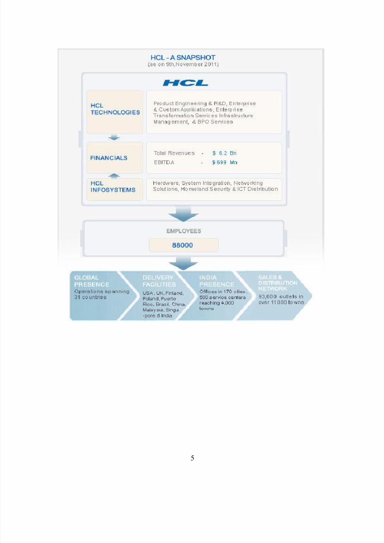
HCL Infosystems is ranked #1 in IDC-Dataquest Customer Satisfaction Survey 2011, third year
in a row. DQ-IDC ranks the company #2 Domestic ICT company. It has been selected as
Business Super brands of India by the Super Brands Council. The company has been awarded
with the CMMI (Capability Maturity Model Integration) Maturity Level 5 certification for its
Jaipur Development centre in 2011.
The 35 year old enterprise, founded in 1976, is one of India's original IT garage start ups. Its
range of offerings span R&D and Technology Services, Enterprise and Applications Consulting,
Remote Infrastructure Management, BPO services, IT Hardware, Systems Integration and
Distribution of Technology and Telecom products in India. The HCL team comprises 88,000
professionals of diverse nationalities, operating across 31 countries including 500 points of
presence in India. HCL has global partnerships with several leading Fortune 1000 firms,including several IT and Technology majors.
Courses
8/13/2019 Network configuration of LAN with MAN
http://slidepdf.com/reader/full/network-configuration-of-lan-with-man 3/78
3
Networking courses
HCE (HCL CERTIFIED ENTERPRISE ENGINEER)
In Today is IT scenario, there is a huge requirement of IT professionals with a firm grasp of
Hardware and Networking Concepts. With the role of an IT professional not restricted to one
technology alone, the industry requires one to have all-round knowledge of computer hardware
& networking concepts and technologies. The average salaries of such network professionals
which have done a complete course range to more than $90,000 per annum. The course is a great
value addition to the candidates who have completed their graduation in Applied Sciences and
Engineering, and IT field.
Taking into consideration the Industry requirements HCL has come up with an Industry Ready
Course known as HCEE (known as HCE+). The various course contents are-
Course Contents & Unique Features
i. Basic Hardware and Server Technology.
ii. Advanced Networking and Security.
iii. System Engineering on Microsoft Technologies.
iv. Networking Technology & Devices.
v. Linux Administration & Security
vi. Service Desk Institute.
vii. Advanced Storage Technology.
HCNE (NETWORK ENGINEER)
With roles of an IT professionals not just constrained to one technology only, Industry demands
people to have al-round knowledge of Computer Hardware and Networking Concepts ranging to
various Technologies. The average salaries of such network professionals which have done a
complete course range to more than $90,000 per annum.
The course creates great job prospects for the candidates who have a keen inclination towards
making their career in managing IT Infrastructure along with their graduation such that when
they complete the course with graduation they are industry ready and the most sought after
professionals.
8/13/2019 Network configuration of LAN with MAN
http://slidepdf.com/reader/full/network-configuration-of-lan-with-man 4/78
4
Course Contents & Unique Features
Taking into consideration the Industry requirements HCL has come up with an Industry Ready
Course known as HCE plus. The various course contents are:
i. Basic Hardware and Server Technology
ii. Advanced Networking and Security
iii. System Engineering on Microsoft Technologies
iv. Networking Technology & Devices
v. Linux Administration & Security
vi. Notebook Technology.
vii. Wireless Network Administration.
HCSA (SYSTEM ADMINISTRATOR)
With the role of an IT professional not restricted to one technology alone, the industry requires
one to have all-round knowledge of computer hardware & networking concepts and technologies
The average salaries of such network professionals which have done a complete course range to
more than $90,000 per annum. The course creates great job prospects for the candidates who
have a keen inclination towards making their career in managing IT Infrastructure along with
their graduation such that when they complete the course with graduation they are industry ready
and the most sought after professionals.
HCSP (SYSTEM PROFESSIONAL)
With the role of an IT professional not restricted to one technology alone, the industry requires
one to have all-round knowledge of computer hardware & networking concepts and
technologies. The average salaries of such network professionals which have done a complete
course range to more than $90,000 per annum. The course creates great job prospects for the
candidates who have a keen inclination towards making their career in managing ITInfrastructure along with their graduation such that when they complete the course with
graduation they are industry ready and the most sought after professionals.
8/13/2019 Network configuration of LAN with MAN
http://slidepdf.com/reader/full/network-configuration-of-lan-with-man 5/78
5

8/13/2019 Network configuration of LAN with MAN
http://slidepdf.com/reader/full/network-configuration-of-lan-with-man 6/78
6
CHAPTER-2
Literature Review
2.1 Network Essentials
1. Networking
Networking is the concept of sharing resources and services. A network of computers is a
group of interconnected systems sharing resources and interacting using a shared
communications link. A network , therefore, is a set of interconnected systems with
something to share. The shared resource can be data, a printer, a fax modem, or a service
such as a database or an email system. The individual systems must be connected through
a pathway (called the transmission medium) that is used to transmit the resource orservice between the computers. All systems on the pathway must follow a set of common
communication rules for data to arrive at its intended destination and for the sending and
receiving systems to understand each other. The rules governing computer
communication are called protocols. All networks must have the following:
i. A resource to share (resource)
ii. A pathway to transfer data (transmission medium)
iii. A set of rules governing how to communicate (protocols)
The two main reasons for using computer networking are to provide services and to
reduce equipment costs. The following are specific reasons for networking PCs:
i. Sharing files
ii. Sharing printers and other devices
iii. Enabling centralized administration and security of the resources within the
system
iv. Supporting network applications such as electronic mail and database services.
Networks come in all shapes and sizes. Network administrators often classify networks
according to geographical size. The following are the most common size classifications:
Local Area Networks (LANs)

8/13/2019 Network configuration of LAN with MAN
http://slidepdf.com/reader/full/network-configuration-of-lan-with-man 7/78
7
A local area network (LAN) is a group of computers and network communication
devices interconnected within a geographically limited area, such as a building or
a campus. LANs are characterized by the following:
They transfer data at high speeds (higher bandwidth).
They exist in a limited geographical area.
Connectivity and resources, especially the transmission media, usually are
managed by the company running the LAN.
Wide Area Networks (WANs)
A wide area network (WAN) interconnects LANs. A WAN can be located entirely
within a state or a country, or it can be interconnected around the world. WANs
are characterized by the following:
They exist in an unlimited geographical area.
They usually interconnect multiple LANs.
They often transfer data at lower speeds (lower bandwidth).
Connectivity and resources, especially the transmission media, usually are
managed by a third-party carrier such as a telephone or cable company.
Fig 2.1 LAN with WAN
Intranet
An intranet is basically a network that is local to a company. In other words, users
from within this company can find all of their resources without having to go
outside of the company. An intranet can include LANs, private WANs and
MANs.
8/13/2019 Network configuration of LAN with MAN
http://slidepdf.com/reader/full/network-configuration-of-lan-with-man 8/78
8
Extranet
An extranet is an extended intranet, where certain internal services are made
available to known external users or external business partners at remote
locations.
Internet
An internet is used when unknown external users need to access
internal resources in your network. In other words, your company might have a
web site that sells various products, and you want any external user to be able to
access this service.
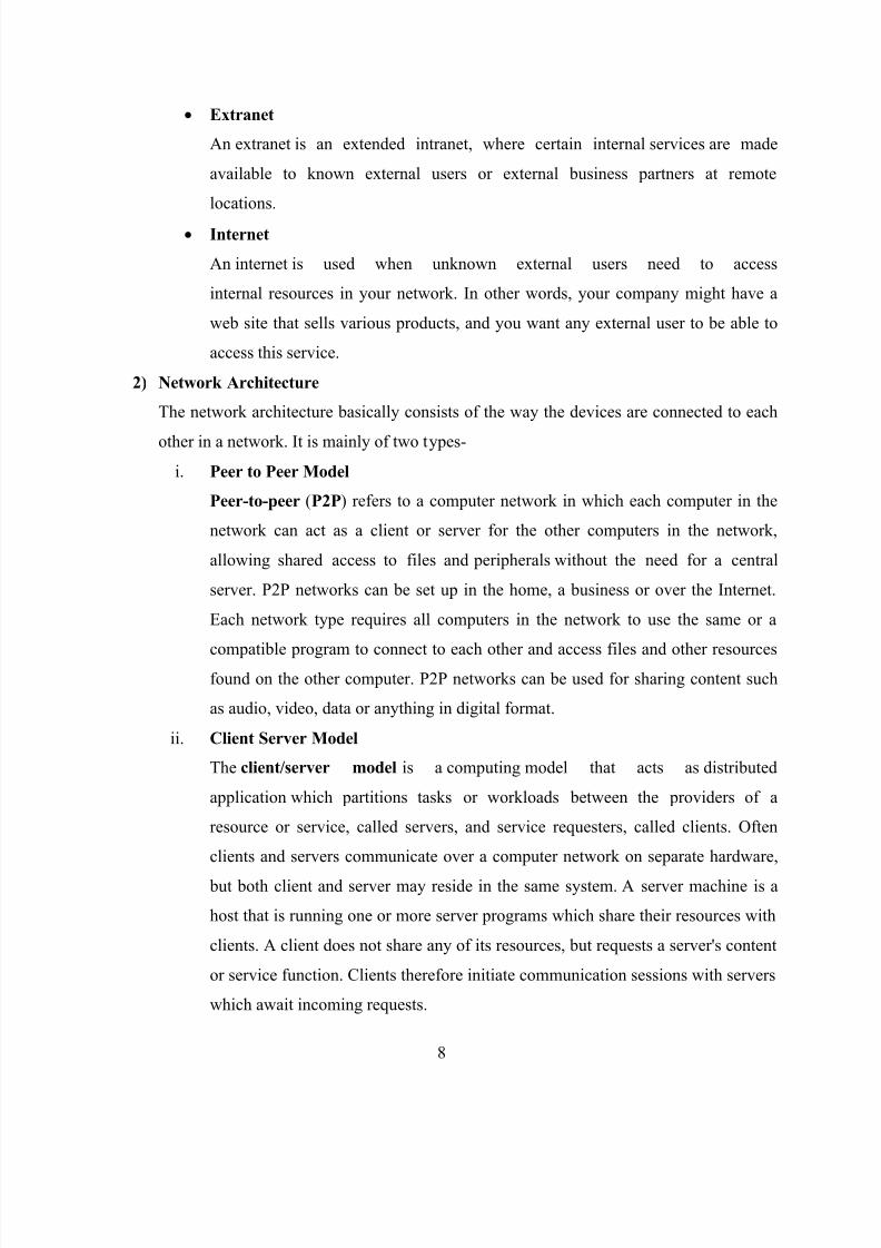
2) Network Architecture
The network architecture basically consists of the way the devices are connected to each
other in a network. It is mainly of two types-
i. Peer to Peer Model
Peer-to-peer (P2P) refers to a computer network in which each computer in the
network can act as a client or server for the other computers in the network,
allowing shared access to files and peripherals without the need for a central
server. P2P networks can be set up in the home, a business or over the Internet.
Each network type requires all computers in the network to use the same or a
compatible program to connect to each other and access files and other resourcesfound on the other computer. P2P networks can be used for sharing content such
as audio, video, data or anything in digital format.
ii. Client Server Model
The client/server model is a computing model that acts as distributed
application which partitions tasks or workloads between the providers of a
resource or service, called servers, and service requesters, called clients. Often
clients and servers communicate over a computer network on separate hardware,
but both client and server may reside in the same system. A server machine is a
host that is running one or more server programs which share their resources with
clients. A client does not share any of its resources, but requests a server's content
or service function. Clients therefore initiate communication sessions with servers
which await incoming requests.

8/13/2019 Network configuration of LAN with MAN
http://slidepdf.com/reader/full/network-configuration-of-lan-with-man 9/78
9
Functions such as email exchange, web access and database access are built on
the client/server model. Many business applications being written today use the
client – server model, as do the Internet's main application protocols, such
as HTTP, SMTP, Telnet, and DNS.
Fig 2.2 Peer to Peer and Client Server Model
3) Network Topology
Network topology is the layout pattern of interconnections of the various elements
(links, nodes, etc.) of a computer or biological network. Network topologies may be
physical or logical. Physical topology refers to the physical design of a network
including the devices, location and cable installation. Logical topology refers to how data
is actually transferred in a network as opposed to its physical design.
A local area network (LAN) is one example of a network that exhibits both a physical
topology and a logical topology. There are two basic categories of network topologies:
a) Physical topologies- The shape of the cabling layout used to link devices is called
the physical topology of the network. This refers to the layout of cabling, the
locations of nodes, and the interconnections between the nodes and the cabling.
The physical topology of a network is determined by the capabilities of the

8/13/2019 Network configuration of LAN with MAN
http://slidepdf.com/reader/full/network-configuration-of-lan-with-man 10/78
10
network access devices and media, the level of control or fault tolerance desired,
and the cost associated with cabling or telecommunications circuits.
The basic Physical Topologies are-
Bus Topology
In local area networks where bus topology is used, each node is connected
to a single cable. Each computer or server is connected to the single bus
cable. A signal from the source travels in both directions to all machines
connected on the bus cable until it finds the intended recipient. If the
machine address does not match the intended address for the data, the
machine ignores the data. Alternatively, if the data matches the machine
address, the data is accepted. Since the bus topology consists of only one
wire, it is rather inexpensive to implement when compared to other
topologies. However, the low cost of implementing the technology is
offset by the high cost of managing the network. Additionally, since only
one cable is utilized, it can be the single point of failure. If the network
cable is terminated on both ends and when without termination data
transfer stop and when cable breaks, the entire network will be down.
Star Topology
In local area networks with a star topology, each network host isconnected to a central hub with a point-to-point connection. The network
does not necessarily have to resemble a star to be classified as a star
network, but all of the nodes on the network must be connected to one
central device. All traffic that traverses the network passes through the
central hub. The hub acts as a signal repeater. The star topology is
considered the easiest topology to design and implement. An advantage of
the star topology is the simplicity of adding additional nodes. The primary
disadvantage of the star topology is that the hub represents a single point
of failure.
Although most networks that are based upon the physical star topology are
commonly implemented using a special device such as a hub or switch as
the central node (i.e., the 'hub' of the star), it is also possible to implement

8/13/2019 Network configuration of LAN with MAN
http://slidepdf.com/reader/full/network-configuration-of-lan-with-man 11/78
11
a network that is based upon the physical star topology using a computer
or even a simple common connection point as the 'hub' or central node.
Ring Topology
A network topology that is set up in a circular fashion in which data
travels around the ring in one direction and each device on the right acts as
a repeater to keep the signal strong as it travels. Each device incorporates a
receiver for the incoming signal and a transmitter to send the data on to the
next device in the ring. The network is dependent on the ability of the
signal to travel around the ring.
Mesh Topology
The number of connections in a full mesh = n(n - 1) / 2.
The physical fully connected mesh topology is generally too costly and
complex for practical networks, although the topology is used when there
are only a small number of nodes to be interconnected.
The Partially connected type of network topology in which some of the
nodes of the network are connected to more than one other node in the
network with a point-to-point link – this makes it possible to take
advantage of some of the redundancy that is provided by a physical fully
connected mesh topology without the expense and complexity required fora connection between every node in the network.
Tree Topology
Tree topology is a combination of Bus and Star topology.
Each node in the network having a specific fixed number, of nodes
connected to it at the next lower level in the hierarchy, the number, being
referred to as the 'branching factor' of the hierarchical tree. This tree has
individual peripheral nodes.
A network that is based upon the physical hierarchical topology must have
at least three levels in the hierarchy of the tree, since a network with a
central 'root' node and only one hierarchical level below it would exhibit
the physical topology of a star.
Such a type of network topology is very useful and highly recommended.

8/13/2019 Network configuration of LAN with MAN
http://slidepdf.com/reader/full/network-configuration-of-lan-with-man 12/78
12
Hybrid Topology
Hybrid topology is a combination of Bus, Star and ring topology.
Hybrid networks use a combination of any two or more topologies in such
a way that the resulting network does not exhibit one of the standard
topologies (e.g., bus, star, ring, etc.). For example, a tree network
connected to a tree network is still a tree network topology. A hybrid
topology is always produced when two different basic network topologies
are connected. Two common examples for Hybrid network are: Star-Ring
network and Star-Bus network
Fig 2.3 Basic Network Topologies
b) Logical topologies-The logical topology, in contrast, is the way that the signals
act on the network media, or the way that the data passes through the network
from one device to the next without regard to the physical interconnection of the
devices. For example, the original twisted pair Ethernet using repeater, hubs was a
logical bus topology with a physical star topology layout. Token Ring is a logical
ring topology, but is wired a physical star from the Media Access Unit.
The logical classification of network topologies describes the path that
the data takes between nodes being used as opposed to the
actual physical connections between nodes.
4) Networking Hardware
8/13/2019 Network configuration of LAN with MAN
http://slidepdf.com/reader/full/network-configuration-of-lan-with-man 13/78
13
Networking hardware or networking equipment typically refers to devices facilitating
the use of a computer network. Computer networking devices are units that
mediate data in a computer network. The various Networking devices are-
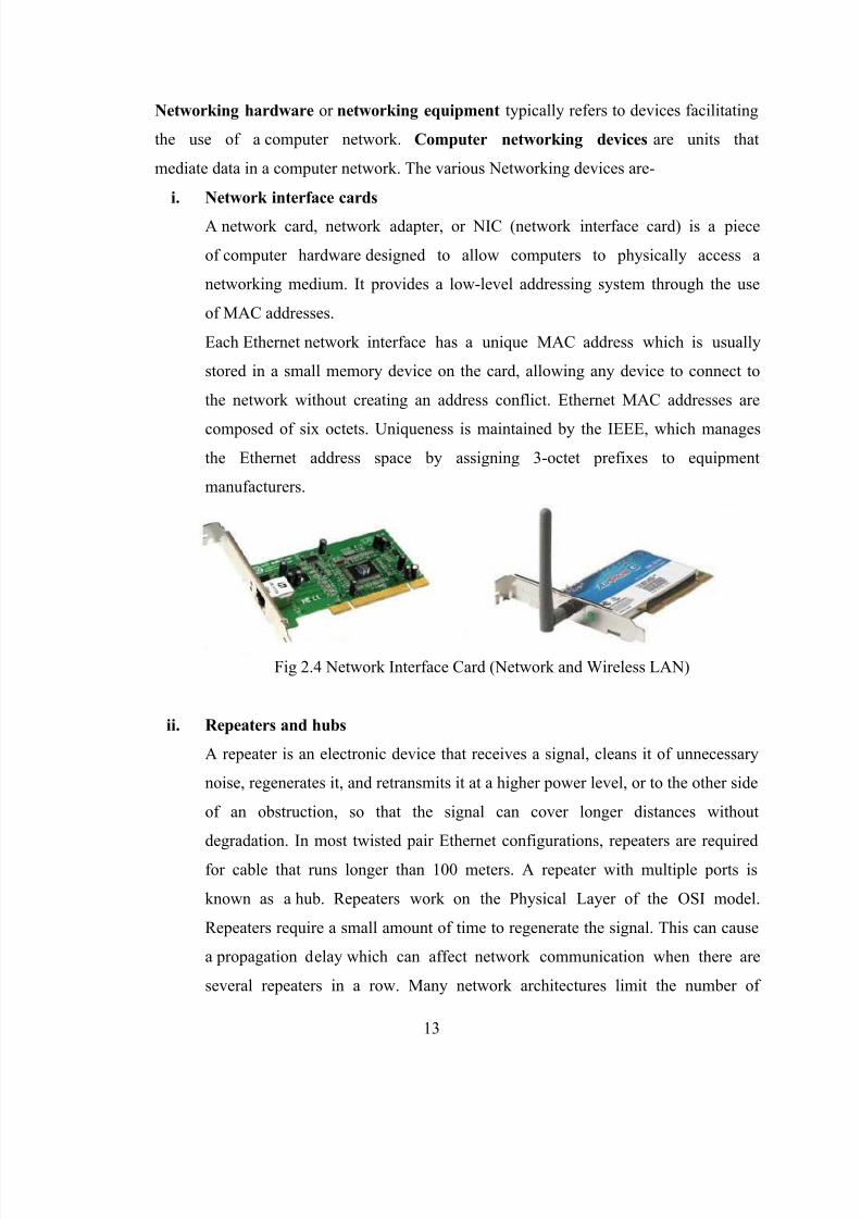
i. Network interface cards
A network card, network adapter, or NIC (network interface card) is a piece
of computer hardware designed to allow computers to physically access a
networking medium. It provides a low-level addressing system through the use
of MAC addresses.
Each Ethernet network interface has a unique MAC address which is usually
stored in a small memory device on the card, allowing any device to connect to
the network without creating an address conflict. Ethernet MAC addresses are
composed of six octets. Uniqueness is maintained by the IEEE, which manages
the Ethernet address space by assigning 3-octet prefixes to equipment
manufacturers.
Fig 2.4 Network Interface Card (Network and Wireless LAN)
ii. Repeaters and hubs
A repeater is an electronic device that receives a signal, cleans it of unnecessary
noise, regenerates it, and retransmits it at a higher power level, or to the other side
of an obstruction, so that the signal can cover longer distances without
degradation. In most twisted pair Ethernet configurations, repeaters are required
for cable that runs longer than 100 meters. A repeater with multiple ports is
known as a hub. Repeaters work on the Physical Layer of the OSI model.
Repeaters require a small amount of time to regenerate the signal. This can cause
a propagation delay which can affect network communication when there are
several repeaters in a row. Many network architectures limit the number of

8/13/2019 Network configuration of LAN with MAN
http://slidepdf.com/reader/full/network-configuration-of-lan-with-man 14/78
14
repeaters that can be used in a row (e.g. Ethernet's 5-4-3 rule). Today, repeaters
and hubs have been made mostly obsolete by switches.
Fig 2.5 Hub- 4 Port and 8 Ports
iii. Bridges
A bridge is used to join two network segments together; it allows computers on
either segment to access resources on the other. They can also be used to divide
large networks into smaller segments. Bridges have all the features of repeaters,
but can have more nodes, and since the network is divided, there is fewer
computers competing for resources on each segment thus improving network
performance.
Fig 2.6 Bridge
iv. Switches
Switches are a special type of hub that offers an additional layer of intelligence to
basic, physical-layer repeater hubs. A switch must be able to read the MAC
address of each frame it receives. This information allows switches to repeat
incoming data frames only to the computer or computers to which a frame is
addressed. This speeds up the network and reduces congestion.
Fig 2.7 Switch
8/13/2019 Network configuration of LAN with MAN
http://slidepdf.com/reader/full/network-configuration-of-lan-with-man 15/78
15
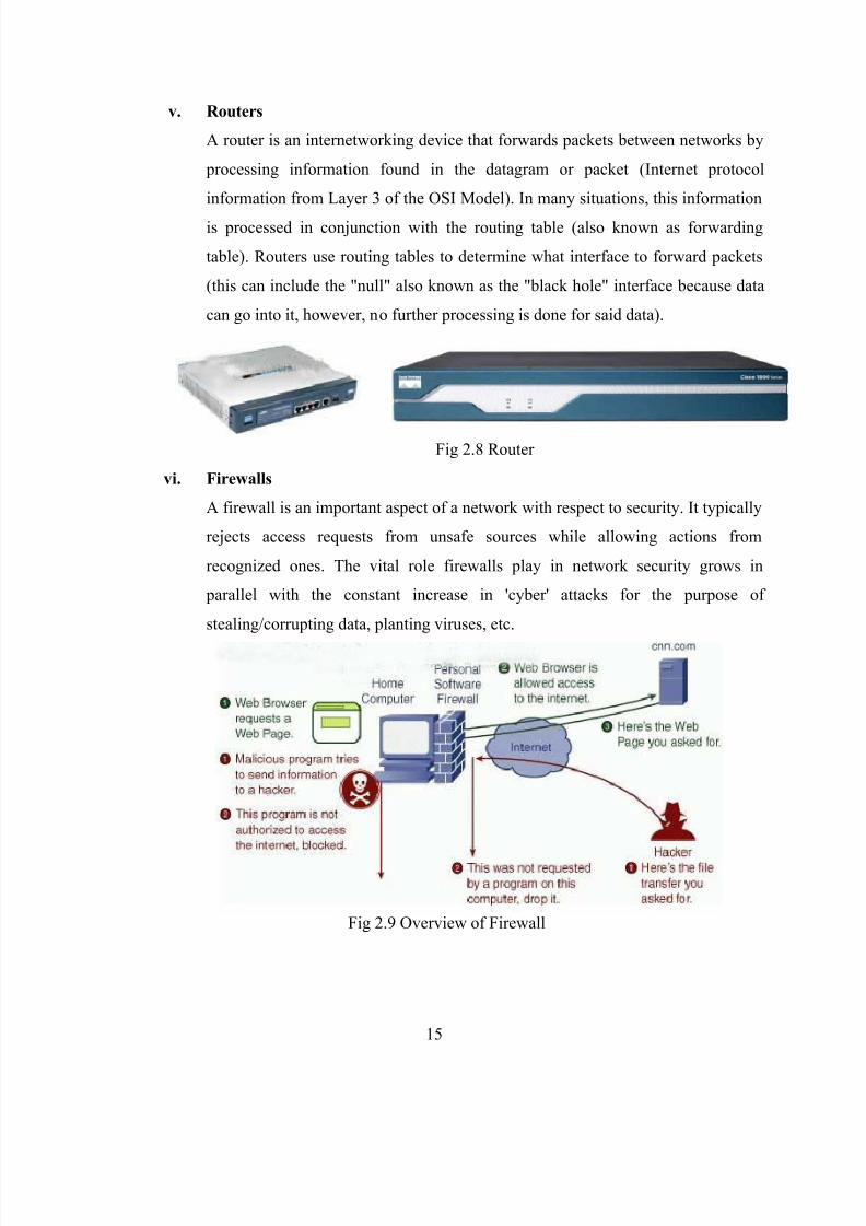
v. Routers
A router is an internetworking device that forwards packets between networks by
processing information found in the datagram or packet (Internet protocol
information from Layer 3 of the OSI Model). In many situations, this information
is processed in conjunction with the routing table (also known as forwarding
table). Routers use routing tables to determine what interface to forward packets
(this can include the "null" also known as the "black hole" interface because data
can go into it, however, no further processing is done for said data).
Fig 2.8 Router
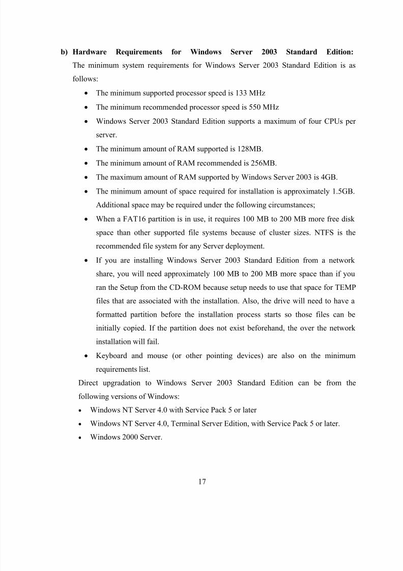
vi. Firewalls
A firewall is an important aspect of a network with respect to security. It typically
rejects access requests from unsafe sources while allowing actions from
recognized ones. The vital role firewalls play in network security grows in
parallel with the constant increase in 'cyber' attacks for the purpose of
stealing/corrupting data, planting viruses, etc.
Fig 2.9 Overview of Firewall

8/13/2019 Network configuration of LAN with MAN
http://slidepdf.com/reader/full/network-configuration-of-lan-with-man 16/78
16
2.2 Microsoft Certified Systems Engineer or MCSE
MCSE stands for the certification course "Microsoft Certified Systems Engineer". The MCSE
program began with Windows NT 3.1 and is today one of the most widely known Microsoft
certification programs. It is available for the Platforms viz., Windows NT 4.0, Windows 2000Server and Windows Server 2003. Microsoft has, in effect, discontinued the MCSE certifications
for future versions of Windows, replacing the single Platform MCSE award with a plethora of
other more narrowly focused certifications.
Each platform MCSE award required passing a different set of examinations. MCSE qualified
individuals will have the ability to provide business solutions by appropriate design and
implementation of the requisite infrastructure. MCSE Certification Program is useful for
Technical Support & Systems Engineers, Technical Consultants, Network and Systems Analysts
and also for regular Software Engineers / Software Professionals.
1) Windows Server 2003 Standard Edition RC2 Installation
The idea behind this article is to give an overview of the Windows Server 2003 Standard
Edition installation procedure as it is currently laid out under the current build, which is RC2
3718.main.021114-1947. That the name used throughout is different than what will show up
in many of the screen shots. This is because the name of Windows .NET Server 2003 has
been changed recently to Windows Server 2003.
a) Windows Server 2003 Family Version Overview
Windows Server 2003 Web Server Edition is designed specifically for low end and entry
level Web hosting environments, providing a specific platform for deploying Web
services and applications.
It is designed with the day to day needs of the average business in mind and is the
progressive replacement for the Windows NT4 Server / Windows 2000 Server line of
server operating systems.
It is designed specifically for the needs of larger customers, as their needs surpass the
functional levels of Windows Server 2003 Standard Edition.
8/13/2019 Network configuration of LAN with MAN
http://slidepdf.com/reader/full/network-configuration-of-lan-with-man 17/78
17
b) Hardware Requirements for Windows Server 2003 Standard Edition:
The minimum system requirements for Windows Server 2003 Standard Edition is as
follows:
The minimum supported processor speed is 133 MHz
The minimum recommended processor speed is 550 MHz
Windows Server 2003 Standard Edition supports a maximum of four CPUs per
server.
The minimum amount of RAM supported is 128MB.
The minimum amount of RAM recommended is 256MB.
The maximum amount of RAM supported by Windows Server 2003 is 4GB.
The minimum amount of space required for installation is approximately 1.5GB.
Additional space may be required under the following circumstances;
When a FAT16 partition is in use, it requires 100 MB to 200 MB more free disk
space than other supported file systems because of cluster sizes. NTFS is the
recommended file system for any Server deployment.
If you are installing Windows Server 2003 Standard Edition from a network
share, you will need approximately 100 MB to 200 MB more space than if you
ran the Setup from the CD-ROM because setup needs to use that space for TEMP
files that are associated with the installation. Also, the drive will need to have a
formatted partition before the installation process starts so those files can be
initially copied. If the partition does not exist beforehand, the over the network
installation will fail.
Keyboard and mouse (or other pointing devices) are also on the minimum
requirements list.
Direct upgradation to Windows Server 2003 Standard Edition can be from the
following versions of Windows: Windows NT Server 4.0 with Service Pack 5 or later
Windows NT Server 4.0, Terminal Server Edition, with Service Pack 5 or later.
Windows 2000 Server.
8/13/2019 Network configuration of LAN with MAN
http://slidepdf.com/reader/full/network-configuration-of-lan-with-man 18/78
18
Remote Storage is not included on Windows Server 2003 Standard Edition. If you are
using Windows 2000 Server with Remote Storage, you will not be able to upgrade the
system to Windows Server 2003 Standard Edition.
You cannot upgrade from Windows 9x, ME, Windows NT Workstation, Windows
2000 Professional and Windows XP Home or Professional directly to any of the
Windows Server 2003 versions.
Clean Install of Windows Server 2003 (RC2)
After performing the standard BIOS configurations to allow booting from the CD-
ROM you can load the bootable disk and begin the installation.
The first screen you'll see will be the black “Setup is inspecting your computer‟s
hardware configuration.” (If there is an active partition on any of the installedhard drives in the system, you will see a "Press any key to boot from the CD"
message before you reach this screen.)
After the drivers load, the Windows Setup screen appears and Setup copies the
required temporary files to the local hard drive after you acknowledge the location
of the setup files.
After the file copy is complete, the Setup Program will append any existing
boot.ini file (or write a new one) and will reboot and continue the installation
from the locally copied temporary files.
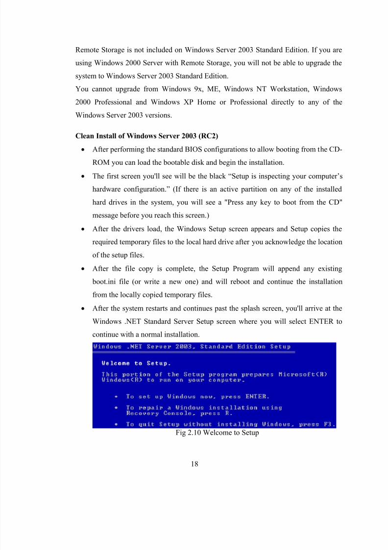
After the system restarts and continues past the splash screen, you'll arrive at the
Windows .NET Standard Server Setup screen where you will select ENTER to
continue with a normal installation.
Fig 2.10 Welcome to Setup
8/13/2019 Network configuration of LAN with MAN
http://slidepdf.com/reader/full/network-configuration-of-lan-with-man 19/78
19
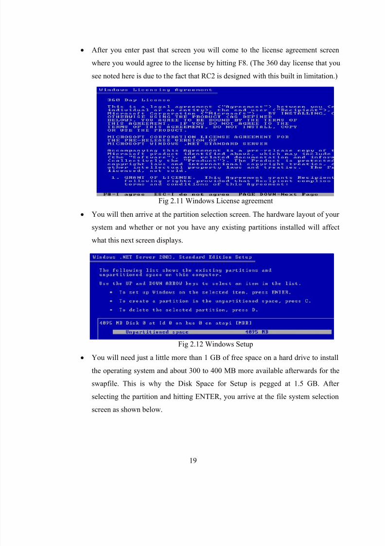
After you enter past that screen you will come to the license agreement screen
where you would agree to the license by hitting F8. (The 360 day license that you
see noted here is due to the fact that RC2 is designed with this built in limitation.)
Fig 2.11 Windows License agreement
You will then arrive at the partition selection screen. The hardware layout of your
system and whether or not you have any existing partitions installed will affect
what this next screen displays.
Fig 2.12 Windows Setup
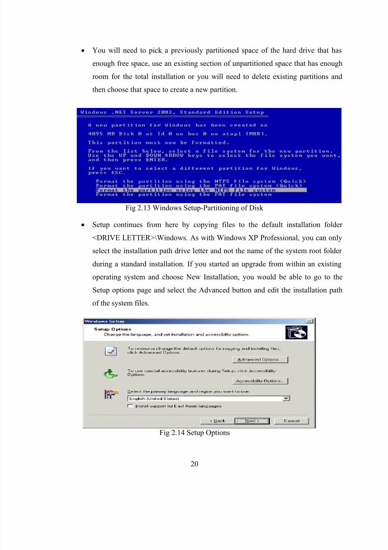
You will need just a little more than 1 GB of free space on a hard drive to install
the operating system and about 300 to 400 MB more available afterwards for the
swapfile. This is why the Disk Space for Setup is pegged at 1.5 GB. After
selecting the partition and hitting ENTER, you arrive at the file system selection
screen as shown below.
8/13/2019 Network configuration of LAN with MAN
http://slidepdf.com/reader/full/network-configuration-of-lan-with-man 20/78
20
You will need to pick a previously partitioned space of the hard drive that has
enough free space, use an existing section of unpartitioned space that has enough
room for the total installation or you will need to delete existing partitions and
then choose that space to create a new partition.
Fig 2.13 Windows Setup-Partitioning of Disk
Setup continues from here by copying files to the default installation folder
<DRIVE LETTER>\Windows. As with Windows XP Professional, you can only
select the installation path drive letter and not the name of the system root folder
during a standard installation. If you started an upgrade from within an existing
operating system and choose New Installation, you would be able to go to the
Setup options page and select the Advanced button and edit the installation path
of the system files.
Fig 2.14 Setup Options
8/13/2019 Network configuration of LAN with MAN
http://slidepdf.com/reader/full/network-configuration-of-lan-with-man 21/78
21
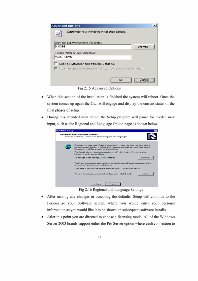
Fig 2.15 Advanced Options
When this section of the installation is finished the system will reboot. Once thesystem comes up again the GUI will engage and display the current status of the
final phases of setup.
During this attended installation, the Setup program will pause for needed user
input, such as the Regional and Language Option page as shown below.
Fig 2.16 Regional and Language Settings
After making any changes or accepting the defaults, Setup will continue to the
Personalize your Software screen, where you would enter your personal
information as you would like it to be shown on subsequent software installs.
After this point you are directed to choose a licensing mode. All of the Windows
Server 2003 brands support either the Per Server option where each connection to

8/13/2019 Network configuration of LAN with MAN
http://slidepdf.com/reader/full/network-configuration-of-lan-with-man 22/78
22
the server must have its own license or Per Device or Per User licensing option
where each person or device must have a client access license.
After you have made your licensing choice and continued, the next window that
will prompt you for information will be the Computer Name and Administrator
Password screen where you will choose the name of the system.
Computer names should be 15 characters or less and they can contain letters (A
through Z), numbers (0 through 9), and hyphens (-), but no spaces or periods (.).
While the names can contain numbers, they cannot consist entirely of numbers.
The maximum allowable length for a computer name is 63 characters.
This same screen is where you will need to enter the password to be used with the
default Administrator account.
Fig 2.17 Check Upgrade
The results screen will appear with any pertinent information after a few
moments.
Fig 2.18 Report System Compatibility

8/13/2019 Network configuration of LAN with MAN
http://slidepdf.com/reader/full/network-configuration-of-lan-with-man 23/78
23
Regardless of whether you intentionally run the pre-installation compatibility
check step ahead of time or not, the Setup Wizard checks hardware and software
compatibility at the beginning of a "standard" installation or upgrade and displays
a report if there are any known incompatibilities.
Fig 2.19 Windows Upgrade Advisor
As you can see, an error is generated as I am not allowed to upgrade from
Windows 2000 Professional to Windows Server 2003.
This does not prevent you from installing Windows Server 2003 as a clean
installation in this particular instance.
For security reasons you should supply a password for the Administrator account.
If you are allowed to leave the Administrator password blank and continue, this
would tell the system that there is no password for this account and this is very
insecure to have in any environment.
After entering the password and verifying it, you would select NEXT to continue
and arrive to the screen where you can set the date, time, and time zone settings.
This is also where you would specify whether the system should automatically
adjust for daylight saving time or not.
The next screen is the Specifying Networking Settings where you can allow the
Typical Settings to be applied. You can also select to Customize the settings now
as well.
The next step of the installation process after Specifying Networking Settings is
the Specifying the Workgroup or Domain Name screen where you would choose
to either have your Windows Server 2003 built as a standalone server in a
workgroup or a member server in a domain.
If you are going to add the server to an existing domain you would need to supply
the necessary credentials at this time if an account for the server hadn't already
been created.
8/13/2019 Network configuration of LAN with MAN
http://slidepdf.com/reader/full/network-configuration-of-lan-with-man 24/78
24
If you choose to add the server to a workgroup you need only to supply the name
of the workgroup.
This is the final interactive step. The Setup program will continue for a few more
minutes on its own. Once it has completed, the setup program will reboot the
server and upon restart it will await user input at the logon screen.
The Configure Your Server Wizard appears on the screen the first time you log on
locally to the server with the administrator account.
You can enable the Configure Your Server Wizard to finish installing optional
components that you chose during setup or add additional components as well.
There are options to configure domain controllers or member servers, file servers,
print servers, Web and media servers, application servers, and networking and
communications servers, all through this wizard.
d) Windows 2003 Service Pack 1 Installation
Microsoft has released Service Pack 1 for Windows Server 2003. The main new features
and changes the service pack will make to your server, Active Directory, and server
applications are listed below.
Security Configuration Wizard:
The Security Configuration Wizard (SCW) is a new feature with Windows 2003SP1, and probably the single largest addition to the OS in the Service Pack. The
main function of the SCW is to reduce the attack surface of the server. It guides
the creation of security policies and setting up minimum functionality depending
on the server role. After installing SP1, the SCW needs to be installed via the
Windows Components window of Add or Remove Programs control panel. The
SCW will then appear in the Administrative Tools folder. The SCW will allow
you to either;
i. Create a new Security policy.
ii. Edit an existing Security policy.
iii. Apply an existing Security policy.
iv. Rollback the last applied Security policy

8/13/2019 Network configuration of LAN with MAN
http://slidepdf.com/reader/full/network-configuration-of-lan-with-man 25/78
25
When creating a new security policy, the SCW has almost 200 different server
roles, which can be added to the policy to define the minimum services, ports and
other functional requirements while providing maximum security. Roles, features,
options, services and ports can be selected and de-selected as required as can
outbound authentication methods, registry settings and audit policies. The final
policy is saved to an XML file which can then be used and modified across
servers and server roles running the SCW.
Access Based Enumeration:
To enable this feature you will need to download and install an additional
component in the form of a msi (abeu.msi) file from the Microsoft Download site.
When it is installed, a new tab will appear on shared folders named “Access
Based Enumeration”.
When enabled, this will change the view users will have of files and folders when
accessing shares held on the Windows 2003 server. Only files and folders the
users have permissions to access will be displayed, and nothing else. Prior to
enabling this change, users could see all files and folders, regardless of
permissions, but would not be able to open denied folders or files.
Add or Remove Programs Filter:
A new tick box has been added to the Add or Remove Programs control panel,called Show Updates. With SP1, only installed programs will display until this
check box is ticked. It will then display both programs and updates together. This
feature can be used by any software vendor, not just Microsoft updates..
Device\Physical Memory Change:
The Device\Physical Memory object is used by applications to access physical
memory. This would be used by applications attempting to read BIOS data. Pre-
SP1 this was controlled by an Access Control List. Service Pack 1 changes this
and now denies all access at User Mode level regardless of user context or
application.
Workgroup
i. A workgroup is Microsoft's terminology for a peer-to-peer Windows
computer network.
8/13/2019 Network configuration of LAN with MAN
http://slidepdf.com/reader/full/network-configuration-of-lan-with-man 26/78
26
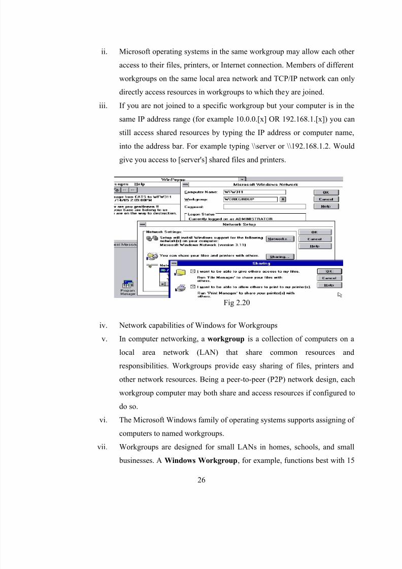
ii. Microsoft operating systems in the same workgroup may allow each other
access to their files, printers, or Internet connection. Members of different
workgroups on the same local area network and TCP/IP network can only
directly access resources in workgroups to which they are joined.
iii. If you are not joined to a specific workgroup but your computer is in the
same IP address range (for example 10.0.0.[x] OR 192.168.1.[x]) you can
still access shared resources by typing the IP address or computer name,
into the address bar. For example typing \\server or \\192.168.1.2. Would
give you access to [server's] shared files and printers.
Fig 2.20
iv. Network capabilities of Windows for Workgroups
v. In computer networking, a workgroup is a collection of computers on a
local area network (LAN) that share common resources and
responsibilities. Workgroups provide easy sharing of files, printers and
other network resources. Being a peer-to-peer (P2P) network design, each
workgroup computer may both share and access resources if configured to
do so.
vi. The Microsoft Windows family of operating systems supports assigning of
computers to named workgroups.
vii. Workgroups are designed for small LANs in homes, schools, and small
businesses. A Windows Workgroup, for example, functions best with 15
8/13/2019 Network configuration of LAN with MAN
http://slidepdf.com/reader/full/network-configuration-of-lan-with-man 27/78
27
or fewer computers. As the number of computers in a workgroup grows,
workgroup LANs eventually become too difficult to administer and should
be replaced with alternative solutions like domains or other client/server
approaches.
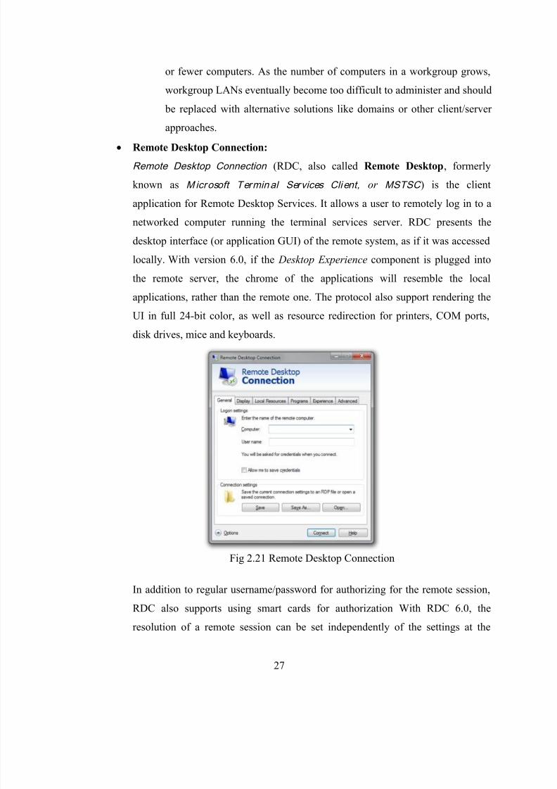
Remote Desktop Connection:
Remote Desktop Connection (RDC, also called Remote Desktop, formerly
known as Microsoft Terminal Services Client , or MSTSC ) is the client
application for Remote Desktop Services. It allows a user to remotely log in to a
networked computer running the terminal services server. RDC presents the
desktop interface (or application GUI) of the remote system, as if it was accessed
locally. With version 6.0, if the Desktop Experience component is plugged into
the remote server, the chrome of the applications will resemble the local
applications, rather than the remote one. The protocol also support rendering the
UI in full 24-bit color, as well as resource redirection for printers, COM ports,
disk drives, mice and keyboards.
Fig 2.21 Remote Desktop Connection
In addition to regular username/password for authorizing for the remote session,
RDC also supports using smart cards for authorization With RDC 6.0, the
resolution of a remote session can be set independently of the settings at the
8/13/2019 Network configuration of LAN with MAN
http://slidepdf.com/reader/full/network-configuration-of-lan-with-man 28/78
28
remote computer. In addition, a remote session can also span multiple monitors at
the client system, independent of the multi-monitor settings at the server. It also
redirects plug and play devices such as cameras, portable music players, and
scanners, so that input from these devices can be used by the remote applications
as well. Desktop Protocol, only the applications can be viewed this way, not any
media.
Windows Remote Assistance
Windows Remote Assistance is a feature of Windows XP and later that allows a
user to temporarily control a remote Windows computer over a network or the
Internet to resolve issues. As it can be inconvenient for system administrators to
personally visit the affected computer, Remote Assistance allows them to
diagnose and often repair problems with a computer without ever personally
visiting it.
It supports session pausing, built-in diagnostics, chat and file transfer and XML-
based logging. It has been reworked to use less bandwidth for low-speed
connections. NAT traversals are also supported, so a session can be established
even if the user is behind a NAT device. Remote Assistance is configurable using
Group Policy and supports command-line switches so that custom shortcuts can
be deployed.

8/13/2019 Network configuration of LAN with MAN
http://slidepdf.com/reader/full/network-configuration-of-lan-with-man 29/78
29
Fig 2.22 Windows Remote Assistance
In Windows 7, Windows Remote Assistance is based on RDP 7 and uses PNRP
when connecting using the Easy Connect option. With Easy Connect , only a
password needs to be shared instead of an invitation file, and two computers can
establish a P2P connection over the LAN (Local Area Network) or the Internet
(WAN) without a relay server.
Windows 7 adds the following new enhancements to Remote Assistance:
i. Easy Connect, a new method for soliciting RA that uses the peer-to-peer
collaboration infrastructure to simplify RA user interactions.
ii. An improved RA connection wizard that makes it easier than ever for
users to solicit or offer help.
iii. New command-line arguments for the RA executable (Msra.exe).
Home folders:
Home folders are separate folders where users save their data and protect their
data from other users every user can have one home folder either on the server on
the local machine. If the home folder is in the server an administrator can secure it

8/13/2019 Network configuration of LAN with MAN
http://slidepdf.com/reader/full/network-configuration-of-lan-with-man 30/78
30
and back-up. If the home folders are created in the local machine backing up is
not that easy.
i. Creating a user home folder in a server :
On member server –
Create a home folder for user1
Share it
Permissions
Remove everyone
Add administrator and user1
Give full control for both
Apply ok
Open ADUC
Create a user a/c
Go to user properties Connect home folder
Select the drive letter
To mention the path
Ex: sys1\u1\home\u1
Apply ok
Verifying: On client machine
Log in as user
Open my computer
We should notice an extra drive letter
Go to cmd prompt
We should not get the drive letter we have assigned.
ii. Creating a local home folder:
On member server –
Login as administrator
Create a folder in any drive
Share it
Permissions Remove everyone
Add administrator &u2
Give full access
Apply – ok
Verifying:
Move on to client machine
8/13/2019 Network configuration of LAN with MAN
http://slidepdf.com/reader/full/network-configuration-of-lan-with-man 31/78
31
Login as user
Go to command prompt.
We should notice the local folder
Active Directory
Active Directory (AD) is a directory service created by Microsoft for Windowsdomain networks. It is included in most Windows Server operating systems.
Server computers on which Active Directory is running are called domain
controllers.
Active Directory serves as a central location for network administration and
security. It is responsible for authenticating and authorizing all users and
computers within a network of Windows domain type, assigning and enforcing
security policies for all computers in a network and installing or updating
software on network computers. For example, when a user logs into a computer
that is part of a Windows domain, it is Active Directory that verifies his or her
password and specifies whether he or she is a system administrator or normal user
Print Server
A print server, or printer server, is a device that connects printers to client
computers over a network. It can accept print jobs from the computers and send
the jobs to the appropriate printers.
Print servers may support a variety of industry-standard or proprietary printing
protocols including Internet Printing Protocol, Line Printer Daemon protocol,
Microsoft Network Printing protocol, NetWare, NetBIOS/NetBEUI, or Jet Direct.
A print server may be a networked computer with one or more shared printers.
Alternatively a print server may be a dedicated device on the network, with
connections to the LAN and one or more printers. Dedicated server appliances
tend to be fairly simple in both configuration and features. Print server
functionality may be integrated with other devices such as a wireless router, a
firewall, or both. A printer may have a built-in print server.
Drive Mapping
Drive mapping is how Microsoft Windows and OS/2 associate a local drive letter
(A through Z) with a shared storage area to another computer over a network.
After a drive has been mapped, a software application on a client's computer can

8/13/2019 Network configuration of LAN with MAN
http://slidepdf.com/reader/full/network-configuration-of-lan-with-man 32/78
32
read and write files from the shared storage area by accessing that drive, just as if
that drive represented a local physical hard disk drive.
Shared Folder
My Shared Folder is a default folder in which several P2P programs store their
downloaded items. The actual directory on the hard disk, that this folder
corresponds to may differ between these programs and may also be changed by
the user. Any user with a P2P-client can download files from the My Shared
Folder belonging to any other person connected to that client at that time.
Offline Files &folders
i. Offline Files is a feature of Windows, introduced in Windows 2000, which
maintains a client side cache of files shared over a network. It locally
caches shared files marked for offline access, and uses the cached copy
whenever the network connection to the remote files is interrupted.
ii. Files are synchronized on a per-share basis and encrypted on a per-user
basis and users can force Windows to work in offline mode or online
mode through the Work Offline/Online button in Explorer, or sync
manually from the Sync Center. Even if a single file is unavailable, other
files in the same share and other shares are available as the transition is
now at the share level instead of server level. Offline Files areconfigurable through Group Policy and provide better interoperability with
DFS.
iii. In Windows XP, Offline Files could not be enabled when Fast User
Switching was enabled. This restriction applied because Offline Files were
synchronized at log off and Fast User Switching does not completely log
off users. In Windows Vista, this restriction no longer applies as Offline
Files runs as a Windows service that performs synchronization for the user
at opportune times such as logon and offline to online transitions.
Synchronization does not occur continuously in the background, nor does
it occur at log off.

8/13/2019 Network configuration of LAN with MAN
http://slidepdf.com/reader/full/network-configuration-of-lan-with-man 33/78
33
Microsoft Exchange Server
Microsoft Exchange Server is the server side of a client – server, collaborative
application product developed by Microsoft. It is part of the Microsoft Servers
line of server products and is used by enterprises using Microsoft infrastructure
products. Exchange's major features consist of electronic mail, calendaring,
contacts and tasks; that work with Microsoft Outlook on PC and Mac, wireless
synchronization of email, calendar, contacts with major mobile devices and
browser-based access to information; and support for data storage.
i. Exchange Server 2003
Exchange Server 2003 (v6.5, code name Titanium) debuted on September
28, 2003. Exchange Server 2003 (currently at Service Pack 2) can be run
on Windows 2000 Server (only if Service Pack 4 is first installed) and 32-
bit Windows Server 2003; although some new features only work with the
latter. Like Windows Server 2003, Exchange Server 2003 has many
compatibility modes to allow users to slowly migrate to the new system.
This is useful in large companies with distributed Exchange Server
environments who cannot afford the downtime and expense that comes
with a complete migration.
Group Policy Group Policy is a feature of the Microsoft Windows NT family of operating
systems. Group Policy is a set of rules that control the working environment of
user and computer accounts. Group Policy provides the centralized management
and configuration of operating systems, applications, and users' settings in an
Active Directory environment. In other words, Group Policy in part controls what
users can and cannot do on a computer system. Although Group Policy is more
often seen in use for enterprise environments, it is also common in schools,
smaller businesses, and other kinds of smaller organizations. Group Policy is
often used to restrict certain actions that may pose potential security risks, for
example: to block access to the Task Manager, restrict access to certain folders,
disable the downloading of executable files, and so on.
Local Group Policy
8/13/2019 Network configuration of LAN with MAN
http://slidepdf.com/reader/full/network-configuration-of-lan-with-man 34/78
34
Local Group Policy (LGP) is a more basic version of the Group Policy used by
Active Directory. In versions of Windows before Windows Vista, LGP can
configure the Group Policy for a single local computer, but unlike Active
Directory Group Policy, cannot make policies for individual users or groups. It
also has far fewer options overall than Active Directory Group Policy.
Domain Name Server
In computing, a domain name server is a program or computer server that
implements a name-service protocol. It maps a human-recognizable identifier to a
system-internal, often numeric, identification or addressing component.
The most prominent types of name servers in operation today are the name
servers of the Domain Name System (DNS), one of the two principal name spaces
of the Internet. The most important function of these DNS servers is the
translation (resolution) of humanly memorable domain names and hostnames into
the corresponding numeric Internet Protocol (IP) addresses, the second principal
Internet name space which is used to identify and locate computer systems and
resources on the Internet.
NAT (Network Address Translation)
In computer networking, network address translation (NAT) is the process of
modifying IP address information in IP packet headers while in transit across atraffic routing device.
The simplest type of NAT provides a one to one translation of IP addresses. RFC
2663 refers to this type of NAT as basic NAT. It is often also referred to as one-
to-one NAT. In this type of NAT only the IP addresses, IP header checksum and
any higher level checksums that include the IP address need to be changed. The
rest of the packet can be left untouched (at least for basic TCP/UDP functionality,
some higher level protocols may need further translation). Basic NATs can be
used when there is a requirement to interconnect two IP networks with
incompatible addressing.
SNAT (Static Network Address Translati on)
The meaning of the term SNAT varies by vendor. Many vendors have
proprietary definitions for SNAT. A common expansion is source NAT, the
8/13/2019 Network configuration of LAN with MAN
http://slidepdf.com/reader/full/network-configuration-of-lan-with-man 35/78
35
counterpart of Destination NAT (DNAT). Microsoft uses the acronym for
Secure NAT, in regard to the ISA Server. For Cisco Systems, SNAT means
stateful NAT.
Dynamic Network Address Translati on
Dynamic NAT, just like static NAT, is not common in smaller networks but is
found within larger corporations with complex networks. The way dynamic
NAT differs from static NAT is that where static NAT provides a one-to-one
internal to public static IP address mapping, dynamic NAT doesn't make the
mapping to the public IP address static and usually uses a group of available
public IP addresses.
Roaming user profile
A roaming user profile is a concept in the Microsoft Windows NT family of
operating systems that allows a user with a computer joined to a Windows Server
domain to log on to any computer on the same network and access their
documents and have a consistent desktop experience, such as applications
remembering toolbar positions and preferences, or the desktop appearance staying
the same.
DHCP (Dynamic Host Configure Protocol)
The Dynamic Host Configuration Protocol (DHCP) is a network configuration protocol for hosts on Internet Protocol (IP) networks. Computers that are
connected to IP networks must be configured before they can communicate with
other hosts. The most essential information needed is an IP address, and a default
route and routing prefix. DHCP eliminates the manual task by a network
administrator. It also provides a central database of devices that are connected to
the network and eliminates duplicate resource assignments.
In addition to IP addresses, DHCP also provides other configuration information,
particularly the IP addresses of local caching DNS resolvers, network boot
servers, or other service hosts. DHCP is used for IPv4 as well as IPv6.
RIS (Remote Installation Services)
RIS, Remote Installation Services is a Microsoft-supplied server that allows PXE
BIOS-enabled computers to remotely execute boot environment variables.

8/13/2019 Network configuration of LAN with MAN
http://slidepdf.com/reader/full/network-configuration-of-lan-with-man 36/78
36
On Windows 2003, two services are required to provide Remote Installation
Services: DHCP and Remote Installation Service. The Remote Installation Server
doubles as a proxy DHCP server to provide Boot Server and Filename
instructions to clients. Remote Installation Service utilizes UDP port 4011 to
provide clients the contents of each page the OS Chooser displays. Additionally,
this service can provide drivers to clients; it is often used to provide the
workstation's network card driver, which is required to launch the OS Chooser
and mount the share where images are stored.
IIS (Internet information services)
Internet Information Services (IIS) – formerly called Internet Information Server
– is a web server application and set of feature extension modules created by
Microsoft for use with Microsoft Windows. It is the most used web server after
Apache HTTP Server. IIS 7.5 supports HTTP, HTTPS, FTP, FTPS, SMTP and
NNTP. It is an integral part of Windows Server family of products, as well as
certain editions of Windows XP, Windows Vista and Windows 7. IIS is not
turned on by default when Windows is installed.
Features-
The architecture of IIS 7 is modular. Modules, also called extensions, can be
added or removed individually so that only modules required for specificfunctionality have to be installed. These modules are individual features that the
server uses to process requests and include the following:
i. HTTP modules – Used to perform tasks specific to HTTP in the request-
processing pipeline, such as responding to information and inquiries sent
in client headers, returning HTTP errors, and redirecting requests.
ii. Security modules – Used to perform tasks related to security in the
request-processing pipeline, such as specifying authentication schemes,
performing URL authorization, and filtering requests.
iii. Content modules – Used to perform tasks related to content in the
request-processing pipeline, such as processing requests for static files,
returning a default page when a client does not specify a resource in a
request, and listing the contents of a directory.
8/13/2019 Network configuration of LAN with MAN
http://slidepdf.com/reader/full/network-configuration-of-lan-with-man 37/78
37
iv. Compression modules – Used to perform tasks related to compression in
the request-processing pipeline, such as compressing responses, applying
Gzip compression transfer coding to responses, and performing pre-
compression of static content.
v. Caching modules – Used to perform tasks related to caching in the
request-processing pipeline, such as storing processed information in
memory on the server and using cached content in subsequent requests for
the same resource.
vi. Logging and Diagnostics modules – Used to perform tasks related to
logging and diagnostics in the request-processing pipeline, such as passing
information and processing status to HTTP.sys for logging, reporting
events, and tracking requests currently executing in worker processes.
Security
Earlier versions of IIS were hit with a number of vulnerabilities, especially the
CA-2001-13 which led to the infamous Code Red worm; however, both versions
6.0 and 7.0 currently have no reported issues with this specific vulnerability. In
IIS 6.0 Microsoft opted to change the behavior of pre-installed ISAPI handlers,
many of which were culprits in the vulnerabilities of 4.0 and 5.0, thus reducing
the attack surface of IIS. In addition, IIS 6.0 added a feature called "Web ServiceExtensions" that prevents IIS from launching any program without explicit
permission by an administrator. In the current release, IIS 7, the components are
provided as modules so that only the required components have to be installed,
thus further reducing the attack surface. In addition, security features are added
such as Request Filtering, which rejects suspicious URLs based on a user-defined
rule set.
Software deployment
Software deployment is all of the activities that make a software system available
for use.
The general deployment process consists of several interrelated activities with
possible transitions between them. These activities can occur at the producer site
or at the consumer site or both. Because every software system is unique, the
8/13/2019 Network configuration of LAN with MAN
http://slidepdf.com/reader/full/network-configuration-of-lan-with-man 38/78
38
precise processes or procedures within each activity can hardly be defined.
Deployment activities
i. Release- The release activity follows from the completed development
process. It includes all the operations to prepare a system for assembly and
transfer to the customer site. Therefore, it must determine the resources
required to operate at the customer site and collect information for
carrying out subsequent activities of deployment process.
ii. Install and Activate- Activation is the activity of starting up the
executable component of software. For simple system, it involves
establishing some form of command for execution. For complex systems,
it should make all the supporting systems ready to use. In larger software
deployments, the working copy of the software might be installed on a
production server in a production environment.
iii. Deactivate- Deactivation is the inverse of activation, and refers to shutting
down any executing components of a system. Deactivation is often
required to perform other deployment activities, e.g., a software system
may need to be deactivated before an update can be performed. The
practice of removing infrequently used or obsolete systems from service is
often referred to as application retirement or application decommissioning.
iv. Adapt- The adaptation activity is also a process to modify a software
system that has been previously installed.
v. Update- The update process replaces an earlier version of all or part of a
software system with a newer release.
vi. Built-In- Mechanisms for installing updates are built into some software
systems. Automation of these update processes ranges from fully
automatic to user initiated and controlled. Norton Internet Security is an
example of a system with a semi-automatic method for retrieving and
installing updates to both the antivirus definitions and other components of
the system.
vii. Version tracking-Version tracking systems help the user find and install
updates to software systems installed on PCs and local networks.

8/13/2019 Network configuration of LAN with MAN
http://slidepdf.com/reader/full/network-configuration-of-lan-with-man 39/78
39
Web based version tracking systems notify the user when updates are
available for software systems installed on a local system. For example:
Version Tracker Pro checks software versions on a user's computer and
then queries its database to see if any updates are available.
viii. Uninstall- Un-installation is the inverse of installation. It is the removal of
a system that is no longer required. It also involves some reconfiguration
of other software systems in order to remove the uninstalled system‟s files
and dependencies.
ix. Retire- Ultimately, a software system is marked as obsolete and support
by the producers is withdrawn. It is the end of the life cycle of a software
product.
Routing and Remote Access Service (RRAS):-
Routing and Remote Access Service (RRAS) is a Microsoft API and server
software make it possible to create applications to administer the routing and
remote access service capabilities of the operating system, to function as a
network router, and developers can also use RRAS to implement routing
protocols. The RRAS server functionality follows and builds upon the Remote
Access Service (RAS).2) IP Addressing
An IP (Internet Protocol) address is a unique identifier for a node or host connection on an IP
network. An IP address is a 32 bit binary number usually represented as 4 decimal values,
each representing 8 bits, in the range 0 to 255 (known as octets) separated by decimal points.
This is known as "dotted decimal" notation.
Example: 140.179.220.200
It is sometimes useful to view the values in their binary form.
141.179.220.200
10001100.10110011.11011100.11001000
Every IP address consists of two parts, one identifying the network and one identifying the
node. The Class of the address and the subnet mask determine which part belongs to the
network address and which part belongs to the node address.

8/13/2019 Network configuration of LAN with MAN
http://slidepdf.com/reader/full/network-configuration-of-lan-with-man 40/78
40
Address Classes
There are 5 different address classes. You can determine which class any IP address is in by
examining the first 4 bits of the IP address.
Class A addresses begin with 0xxx, or 1 to 126 decimal.
Class B addresses begin with 10xx, or 128 to 191 decimal.
Class C addresses begin with 110x, or 192 to 223 decimal.
Class D addresses begin with 1110, or 224 to 239 decimal.
Class E addresses begin with 1111, or 240 to 254 decimal.
Addresses beginning with 01111111, or 127 decimal, are reserved for loopback and for
internal testing on a local machine; [You can test this: you should always be able to
ping 127.0.0.1, which points to yourself] Class D addresses are reserved for multicasting;
Class E addresses are reserved for future use. They should not be used for host addresses.
Now we can see how the Class determines, by default, which part of the IP address belongs
to the network ( N, in blue) and which part belongs to the node (n, in red).
Class A -- NNNNNNNN.nnnnnnnn.nnnnnnnn.nnnnnnnn
Class B -- NNNNNNNN. NNNNNNNN.nnnnnnnn.nnnnnnnn
Class C -- NNNNNNNN. NNNNNNNN. NNNNNNNN.nnnnnnnn
In the example, 140.179.220.200 is a Class B address so by default the Network part of the
address (also known as the Network Address) is defined by the first two octets (140.179.x.x)
and the node part is defined by the last 2 octets (x.x.220.200).
In order to specify the network address for a given IP address, the node section is set to all
"0"s. In our example, 140.179.0.0 specifies the network address for 140.179.220.200. When
the node section is set to all "1"s, it specifies a broadcast that is sent to all hosts on the
network. 140.179.255.255 specifies the example broadcast address. Note that this is true
regardless of the length of the node section.
Private Subnets
There are three IP network addresses reserved for private networks. The addresses
are 10.0.0.0, Subnet Mask 255.0.0.0, 172.16.0.0, Subnet Mask 255.240.0.0,
and 192.168.0.0, Subnet Mask 255.255.0.0. These addresses are also
notated 10.0.0.0/8, 172.16.0.0/12, and 192.168.0.0/16; this notation will be explained later in
this tutorial. They can be used by anyone setting up internal IP networks, such as a lab or

8/13/2019 Network configuration of LAN with MAN
http://slidepdf.com/reader/full/network-configuration-of-lan-with-man 41/78
41
home LAN behind a NAT or proxy server or a router. It is always safe to use these because
routers on the Internet by default will never forward packets coming from these addresses.
These addresses are defined in RFC 1918.
3) Subnetting
Subnetting an IP Network can be done for a variety of reasons, including organization, use of
different physical media (such as Ethernet, FDDI, WAN, etc.), preservation of address space,
and security. The most common reason is to control network traffic. In an Ethernet network,
all nodes on a segment see all the packets transmitted by all the other nodes on that segment.
Performance can be adversely affected under heavy traffic loads, due to collisions and the
resulting retransmissions. A router is used to connect IP networks to minimize the amount of
traffic each segment must receive.
Subnet Masking
Applying a subnet mask to an IP address allows you to identify the network and node
parts of the address. The network bits are represented by the 1s in the mask, and the node
bits are represented by the 0s. Performing a bitwise logical AND operation between the
IP address and the subnet mask results in the Network Address or Number.
For example, using our test IP address and the default Class B subnet mask, we get:
10001100.10110011.11110000.11001000 140.179.240.200 Class B IP Address
11111111.11111111.00000000.00000000 255.255.000.000 Default Class B SubnetMask
10001100.10110011.00000000.00000000 140.179.000.000 Network Address
Default subnet masks:
Class A - 255.0.0.0 - 11111111.00000000.00000000.00000000
Class B - 255.255.0.0 - 11111111.11111111.00000000.00000000
Class C - 255.255.255.0 - 11111111.11111111.11111111.00000000
More Restrictive Subnet Masks
Additional bits can be added to the default subnet mask for a given Class to further
subnet, or break down, a network. When a bitwise logical AND operation is performed
between the subnet mask and IP address, the result defines the Subnet Address (also
called the Network Address or Network Number ). There are some restrictions on the
subnet address.
8/13/2019 Network configuration of LAN with MAN
http://slidepdf.com/reader/full/network-configuration-of-lan-with-man 42/78
42
Node addresses of all "0"s and all "1"s are reserved for specifying the local network
(when a host does not know its network address) and all hosts on the network (broadcast
address), respectively. This also applies to subnets. A subnet address cannot be all "0"s or
all "1"s. This also implies that a 1 bit subnet mask is not allowed.
To calculate the number of subnets or nodes, use the formula (2n-2) where n = number of
bits in either field, and 2n represents 2 raised to the nth power. Multiplying the number of
subnets by the number of nodes available per subnet gives you the total number of nodes
available for your class and subnet mask. Also, note that although subnet masks with
non-contiguous mask bits are allowed, they are not recommended.
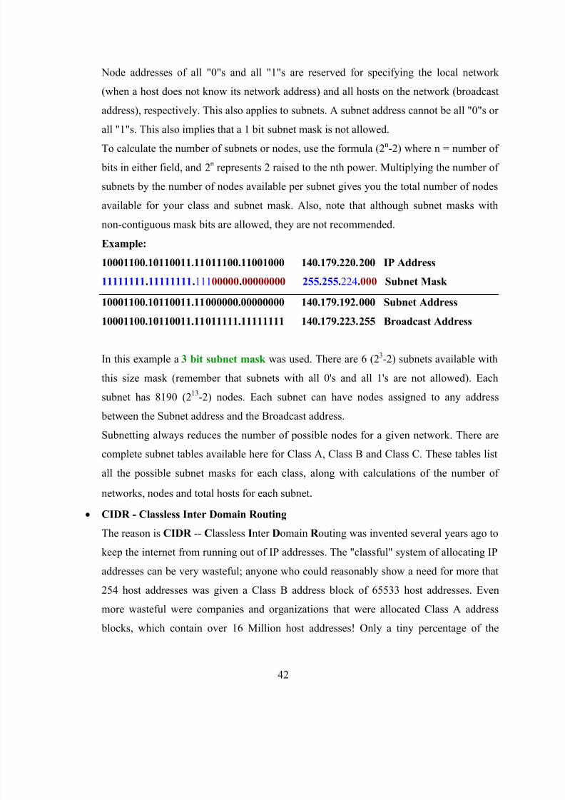
Example:
10001100.10110011.11011100.11001000 140.179.220.200 IP Address
11111111.11111111.11100000.00000000 255.255.224.000 Subnet Mask
10001100.10110011.11000000.00000000 140.179.192.000 Subnet Address
10001100.10110011.11011111.11111111 140.179.223.255 Broadcast Address
In this example a 3 bit subnet mask was used. There are 6 (23-2) subnets available with
this size mask (remember that subnets with all 0's and all 1's are not allowed). Each
subnet has 8190 (213-2) nodes. Each subnet can have nodes assigned to any address
between the Subnet address and the Broadcast address.Subnetting always reduces the number of possible nodes for a given network. There are
complete subnet tables available here for Class A, Class B and Class C. These tables list
all the possible subnet masks for each class, along with calculations of the number of
networks, nodes and total hosts for each subnet.
CIDR - Classless Inter Domain Routing
The reason is CIDR -- Classless Inter Domain R outing was invented several years ago to
keep the internet from running out of IP addresses. The "classful" system of allocating IP
addresses can be very wasteful; anyone who could reasonably show a need for more that
254 host addresses was given a Class B address block of 65533 host addresses. Even
more wasteful were companies and organizations that were allocated Class A address
blocks, which contain over 16 Million host addresses! Only a tiny percentage of the

8/13/2019 Network configuration of LAN with MAN
http://slidepdf.com/reader/full/network-configuration-of-lan-with-man 43/78
43
allocated Class A and Class B address space has ever been actually assigned to a host
computer on the Internet.
People realized that addresses could be conserved if the class system was eliminated. By
accurately allocating only the amount of address space that was actually needed, the
address space crisis could be avoided for many years. This was first proposed in 1992 as
a scheme called Supernetting. Under supernetting, the classful subnet masks are
extended so that a network address and subnet mask could, for example, specify multiple
Class C subnets with one address. For example, If I needed about 1000 addresses, I could
supernet 4 Class C networks together:
192.60.128.0 (11000000.00111100.10000000.00000000) Class C subnet address
192.60.129.0 (11000000.00111100.10000001.00000000) Class C subnet address
192.60.130.0 (11000000.00111100.10000010.00000000) Class C subnet address
192.60.131.0 (11000000.00111100.10000011.00000000) Class C subnet address
--------------------------------------------------------
192.60.128.0 (11000000.00111100.10000000.00000000) Supernetted Subnet address
255.255.252.0 (11111111.11111111.11111100.00000000) Subnet Mask
192.60.131.255 (11000000.00111100.10000011.11111111) Broadcast address
In this example, the subnet 192.60.128.0 includes all the addresses from 192.60.128.0 to
192.60.131.255. As you can see in the binary representation of the subnet mask, the
Network portion of the address is 22 bits long, and the host portion is 10 bits long.
Under CIDR, the subnet mask notation is reduced to simplified shorthand. Instead of
spelling out the bits of the subnet mask, it is simply listed as the number of 1s bits that
start the mask. In the above example, instead of writing the address and subnet mask as
192.60.128.0, Subnet Mask 255.255.252.0
The network address would be written simply as:
192.60.128.0/22Which indicates starting address of the network, and number of 1s bits (22) in the
network portion of the address. If you look at the subnet mask in binary
(11111111.11111111.11111100.00000000), you can easily see how this notation works.
8/13/2019 Network configuration of LAN with MAN
http://slidepdf.com/reader/full/network-configuration-of-lan-with-man 44/78
44
2.3 Cisco Certified Network Associate or CCNA
1) Router
Router is hardware device, which is used to communicate two different networks. Router
performs routing and path determination. It does not perform broadcast information.
There are two types of routers: -
(i) Hardware Routers are developed by Cisco, HP.
(ii) Software Routers is configured with the help of routing and remote
access. This feature is offered by Microsoft. This feature is by default
installed, but you have to enable or configure it.
Hardware routers are dedicated routers. They are more efficient. But in case of software
routers, it has fewer features, slow performance. They are not very much efficient.
2) Lan Card
LAN card is media access device. LAN card provide us connectivity in the network.
There is a RJ45 (Registered Jack) connector space on the LAN card. RJ45 is used in UTP
cable. There is another led which is also called heartbeat of Lan card. When any activity
occur it may be receiving or transmitting any kind of data. This led start blinking and also
tell us the status of lan card.
LAN Topologies BUS Topology
Cable Type – Coaxial
Connector Type – BNC (Bayonet Neill-Concelman), T type, Terminator
Coaxial – Thick Maximum length – 500 meters N/w devices 100
Coaxial – Thin Maximum length – 185 meters N/w devices 30
Fig 2.23

8/13/2019 Network configuration of LAN with MAN
http://slidepdf.com/reader/full/network-configuration-of-lan-with-man 45/78
45
Star Topology
Cable type - UTP
Connector type - RJ45
Maximum Length – 100 meters (with proper color coding)
UTP (Unshielded Twisted Pair)
Fig 2.24 UTP
STP (Shielded Twisted Pair)
Fig 2.25 STP
In case of hub media access method will be CSMA/CD.
Ethernet Family
Speed Base band
10 Base 2 200-meter Coaxial cable
10 Base 5 500-meter Thick Coaxial cable
10 Base T 100 meter Twisted Pair (UTP)
10/100(present) Base TX 100 meter UTP
100 Base T4 100 meter UTP 4 Pairs used
100 Base FX up to 4 kms Fiber Optic
1000(Server) Base TX 100 meter UTP
1000 Base FX up to 10 kms Fiber Optic
10000 Base FX Fiber Optic
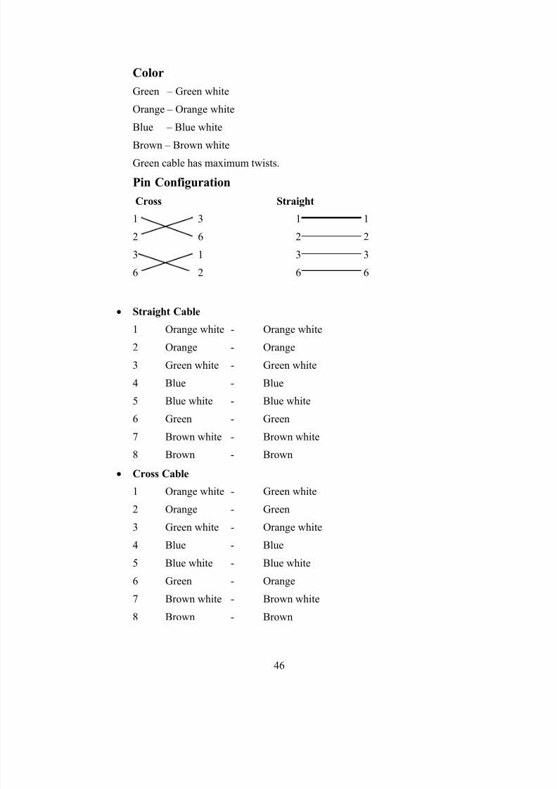
8/13/2019 Network configuration of LAN with MAN
http://slidepdf.com/reader/full/network-configuration-of-lan-with-man 46/78
46
Color
Green – Green white
Orange – Orange white
Blue – Blue white
Brown – Brown white
Green cable has maximum twists.
Pin Configuration
Cross Straight
1 3 1 1
2 6 2 2
3 1 3 3
6 2 6 6
Straight Cable
1 Orange white - Orange white
2 Orange - Orange
3 Green white - Green white
4 Blue - Blue
5 Blue white - Blue white
6 Green - Green
7 Brown white - Brown white
8 Brown - Brown
Cross Cable
1 Orange white - Green white
2 Orange - Green
3 Green white - Orange white
4 Blue - Blue
5 Blue white - Blue white
6 Green - Orange
7 Brown white - Brown white
8 Brown - Brown
8/13/2019 Network configuration of LAN with MAN
http://slidepdf.com/reader/full/network-configuration-of-lan-with-man 47/78
47
RJ45 Connector
Fig 2.26 RJ45
3) OSI (Open Systems Interconnection) Model
OSI model is the layer approach to design, develop and implement network. OSI
provides following advantages: -
(i) Designing of network will be standard base.
(ii) Development of new technology will be faster.
(iii) Devices from multiple vendors can communicate with each other.
(iv) Implementation and troubleshooting of network will be easy.
The seven Layers of OSI model are explained as-
i) Application Layer: - Application layer accepts data and forward into the protocol stack.
It creates user interface between application software and protocol stack.
ii) Presentation Layer: - This layer decides presentation format of the data. It also able to
performs other function like compression/decompression and encryption/decryption.
iii) Session Layer: - This layer initiate, maintain and terminate sessions between different
applications. Due to this layer multiple application software can be executed at the same
time.
iv) Transport Layer: - Transport layer is responsible for connection oriented and
connection less communication. Transport layer also performs other functions like
Error checking, Flow Control, Buffering, Windowing
Multiplexing, Sequencing, Positive Acknowledgement, Response
v) Network Layer: - This layer performs function like logical addressing and path
determination. Each networking device has a physical address that is MAC address. But
logical addressing is easier to communicate on large size network.
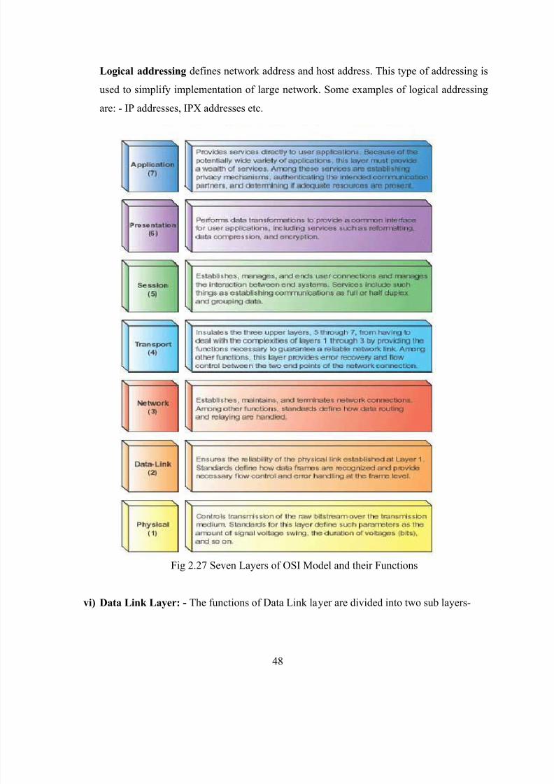
8/13/2019 Network configuration of LAN with MAN
http://slidepdf.com/reader/full/network-configuration-of-lan-with-man 48/78
48
Logical addressing defines network address and host address. This type of addressing is
used to simplify implementation of large network. Some examples of logical addressing
are: - IP addresses, IPX addresses etc.
Fig 2.27 Seven Layers of OSI Model and their Functions
vi) Data Link Layer: - The functions of Data Link layer are divided into two sub layers-
8/13/2019 Network configuration of LAN with MAN
http://slidepdf.com/reader/full/network-configuration-of-lan-with-man 49/78
49
Logical Link Control defines the encapsulation that will be used by the NIC to
delivered data to destination. Some examples of Logical Link Control are ARPA
(Ethernet), 802.11, Wi-Fi.
Media Access Control defines methods to access the shared media and establish
the identity with the help of MAC address. Some examples of Media Access
Control are CSMA/CD, Token Passing.
vii) Physical Layer: - Physical Layer is responsible to communicate bits over the media this
layer deals with the standard defined for media and signals. This layer may also perform
modulation and demodulation as required.
4) Router Configuration
I. Router Access Modes
When we access router command prompt the router will display different modes.
According to the modes, privileges and rights are assigned to the user.
User mode-In this mode, we can display basic parameter and status of the router
we can test connectivity and perform telnet to other devices. In this mode we are
not enable to manage & configure router.
Privileged mode-In this mode, we can display all information, configuration,
perform administration task, debugging, testing and connectivity with other
devices. We are not able to perform here configuration editing of the router.
The command to enter in this mode is „enable‟. We have to enter enable password
or enable secret password to enter in this mode. Enable secret has more priority
than enable password. If both passwords are configured then only enable secret
will work.
Global configuration-This mode is used for the configuration of global
parameters in the router. Global parameters applied to the entire router . For eg: -
router hostname or access list of router. The command Enter in this mode is „configure terminal‟.
II. Line configuration mode
This mode is used to configure lines like console, vty and auxiliary. There are
main types of line that are configured.
(i) Console- Router(config)#line console 0
8/13/2019 Network configuration of LAN with MAN
http://slidepdf.com/reader/full/network-configuration-of-lan-with-man 50/78
50
(ii) Auxiliary- Router(config)#line aux 0
(iii) Telnet or vty- Router(config)#line vty 0 4
III. Interface configuration mode
This mode is used to configure router interfaces. For e.g:- Ethernet, Serial, BRI
etc.
Router (config) #interface <type> <number>
Router (config) #interface serial 1
IV. Routing configuration mode
This mode is used to configure routing protocol like RIP, EIGRP, OSPF etc.
Router (config) #router <protocol> [<option>]
Router (config) #router rip
Router (config) #router eigrp 10
V. Configuring Password
There are five types of password available in a router
(1) Console PasswordRouter#configure terminal
Router(config)#line console 0
Router(config-line)#password <word>
Router(config-line)#login
Router(config-line)#exit
To erase password do all steps with no command.
(2) Vty PasswordRouter>enable
Router#configure terminal
Router(config)#line vty 0 4
Router(config-line)#password <word>
Router(config-line)#login
Router(config-line)#exit
(3) Auxi li ary PasswordRouter#configure terminal
Router(config)#line Aux 0

8/13/2019 Network configuration of LAN with MAN
http://slidepdf.com/reader/full/network-configuration-of-lan-with-man 51/78
51
Router(config-line)#password <word>
Router(config-line)#login
Router(config-line)#exit
(4) Enable PasswordRouter>enable
Router#configure terminal
Router(config)#enable password <word>
Router(config)#exit
(5) Enable Secret PasswordEnable Password is the clear text password.
Router>enable
Router#configure terminal
Router(config)#enable secret <word>
Router(config)#exit
(6) Encryption all passwordsAll passwords other than enable secret password are clear text password. We
can encrypt all passwords using level 7 algorithms. The command to encrypt
all passwords are-
Router#configure terminal
Router(config)#service password-encryption
VI. Managing Configuration
There are two types of configuration present in a router
(1) Startup Configuration
(2) Running Configuration
Startup configuration is stored in the NVRAM. Startup configuration is used to
save settings in a router. Startup configuration is loaded at the time of booting in
to the Primary RAM.
Running Configuration is present in the Primary RAM wherever we run a
command for configuration; this command is written in the running configuration.
To save confi guration
Router#copy running-configuration startup-configuration
8/13/2019 Network configuration of LAN with MAN
http://slidepdf.com/reader/full/network-configuration-of-lan-with-man 52/78
52
Or
Router#write
To display runni ng-conf iguration Router#show running-configuration
To display startup conf igurati on
Router#show startup-configuration
To erase old confi guration
Router#erase startup-configuration
Configuring Host Name
Router#configure terminal
Router#hostname <name>
<name>#exi t or end or /\z
VII. Configuration Interfaces
Interfaces configuration is one of the most important part of the router
configuration. By default, all interfaces of Cisco router are in disabled mode. We
have to use different commands as our requirement to enable and configure the
interface.
Configuring IP, Mask and Enabling the Interface
Router#configure terminal
Router(config)#interface <type> <no>
Router(config-if)#ip address <ip> <mask>
Router(config-if)#no shutdown
Router(config-if)#exit
To conf igure I nterface description
Router#configure terminal
Router(config)#interface <type> <no.>
Router(config-if)#description <line>
To display interface status
Router#show interfaces (to show all interfaces)
Router#show interface <type> <no.>
This command will display following parameters about an interface
1) Status

8/13/2019 Network configuration of LAN with MAN
http://slidepdf.com/reader/full/network-configuration-of-lan-with-man 53/78
53
2) Mac address
3) IP address
4) Subnet mask
5) Hardware type / manufacturer
6) Bandwidth
7) Reliability
8) Delay
9) Load ( Tx load, Rx load)
10) Encapsulation
11) ARP type (if applicable)
12) Keep alive
Configuring secondary IP
Router#config terminal

8/13/2019 Network configuration of LAN with MAN
http://slidepdf.com/reader/full/network-configuration-of-lan-with-man 54/78
54
Router(config)#interface <type> <no>
Router(config-if)#IP address 192.168.10.5 255.255.255.0
Router(config-if)#IP address 192.168.10.18 255.255.255.0 secondary
Router(config-if)#no shutdown (to enable the interface because they
always shutdown)
Router(config-if)#exit
Router#show run (to display secondary IP)
To display commands present i n history
Router#show history
To display history size
Router#show terminal
VIII. Configuring Banners
Banners are just a message that can appear at different prompts according to the
type. Different banners are: -
Message of the day (motd)-This banner appear at every access method.
5) IP Routing
When we want to connect two or more networks using different n/w addresses then we
have to use IP Routing technique. The router will be used to perform routing between the
networks. A router will perform following functions for routing.
I. Path determination
The process of obtaining path in routing table is called path determination. There
are three different methods to which router can learn path.
Automatic detection of directly connected networks.
Static & Default routing
Dynamic routing
II. Packet forwarding
It is a process that is by default enable in router. The router will perform packet
forwarding only if route is available in the routing table.
III. Static Routing
In this routing, we have to use IP route commands through which we can specify
routes for different networks. The administrator will analyze whole internetwork

8/13/2019 Network configuration of LAN with MAN
http://slidepdf.com/reader/full/network-configuration-of-lan-with-man 55/78
55
topology and then specify the route for each n/w that is not directly connected to
the router.
Steps to perform static routing-
a. Create a list of all n/w present in internetwork.
b. Remove the n/w address from list, which is directly connected to n/w.
c. Specify each route for each routing n/w by using IP route command.
Router(config)#ip route <destination n/w> <mask> <next hop ip>
Next hop IP it is the IP address of neighbor router that is directly
connected our router.
Static Routing Example: -
Router#conf ter
Router(config)#ip route 10.0.0.0 255.0.0.0 192.168.10.2
Advantages of static routing
a. Fast and efficient.
b. More control over selected path.
c. Less overhead for router.
Disadvantages of static routing
a. More overheads on administrator.
b. Load balancing is not easily possible.
c. In case of topology change routing table has to be change
manually.
IV. Default Routing
Default routing means a route for any n/w. these routes are specify with the help
of following syntax: -
Router(config)#ip route 0.0.0.0 0.0.0.0 <next hop>
To display routing table
Router#show ip route
To check all the in terf ace of a router
Router#show interface brief
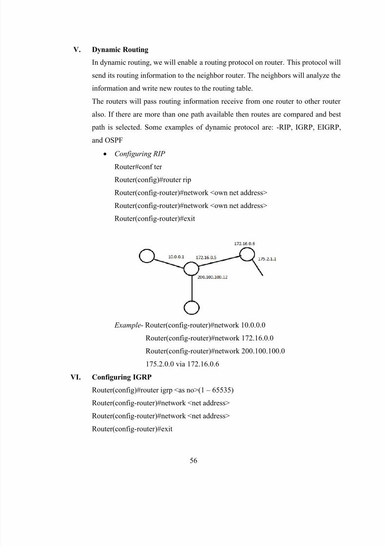
8/13/2019 Network configuration of LAN with MAN
http://slidepdf.com/reader/full/network-configuration-of-lan-with-man 56/78
56
V. Dynamic Routing
In dynamic routing, we will enable a routing protocol on router. This protocol will
send its routing information to the neighbor router. The neighbors will analyze the
information and write new routes to the routing table.
The routers will pass routing information receive from one router to other router
also. If there are more than one path available then routes are compared and best
path is selected. Some examples of dynamic protocol are: -RIP, IGRP, EIGRP,
and OSPF
Configuring RIP
Router#conf ter
Router(config)#router rip
Router(config-router)#network <own net address>
Router(config-router)#network <own net address>
Router(config-router)#exit
Example- Router(config-router)#network 10.0.0.0
Router(config-router)#network 172.16.0.0
Router(config-router)#network 200.100.100.0
175.2.0.0 via 172.16.0.6
VI. Configuring IGRP
Router(config)#router igrp <as no>(1 – 65535)
Router(config-router)#network <net address>
Router(config-router)#network <net address>
Router(config-router)#exit
8/13/2019 Network configuration of LAN with MAN
http://slidepdf.com/reader/full/network-configuration-of-lan-with-man 57/78
57
VII. Link State Routing
This type of routing is based on link state. The router will send link state
information to the all neighbors. Link state information from one neighbor is also
forwarded to other neighbor.
Each router will maintain its link state database created from link state
advertisement received from different routers.
The router will use best path algorithm to store the path in routing table.
Problems of Link State Routing
The main problems of link state routing are: -
High bandwidth consumption.
More hardware resources required that is processor and memory (RAM)
The routing protocols, which use link state routing are: -
a. EIGRP (Enhanced Interior Gateway Routing Protocol)
Features: -
Cisco proprietary
Hybrid protocol
Link State
Distance Vector
Multicast Updates using
Address 224.0.0.10
Support AS
Support VLSM
Automatic Route Summarization
Unequal path cost load balancing
Confi guring EIGRP: -
Router(config)#router eigrp <as no>
Router(config-router)#network <net addr.>
Router(config-router)#network <net addr.>
Router(config-router)#exit
b. OSPF Terminology

8/13/2019 Network configuration of LAN with MAN
http://slidepdf.com/reader/full/network-configuration-of-lan-with-man 58/78
58
Router ID-Router ID is the highest IP address of router interfaces. This id
is used as the identity of the router. It maintains link state databases. The
first preference for selecting router ID is given to the Logical interfaces. If
logical interface is not present then highest IP of physical interface is
selected as router id.
Backup Designated Router-This router will work as backup for the
designated router. In BDR mode, it will receive all information but do not
forward this information to other non-DR router.
Confi guring OSPF-
Router#conf ter
Router(config)#router ospf <process no>
Router(config-router)#network <net address> <wild mask> area <area id>
Router(config-router)#network <net address> <wild mask> area <area id>
Router(config-router)#exit
Wild Mask – Complement of subnet mask
Example 255.255.255.255
- 255.255.192.0 subnet mask
0.0.63.255 wild mask
Example of OSPF Routing-
Router(config)#router ospf 33
Router(config-router)#network 200.100.100.32 0.0.0.3 area 0
Router(config-router)#network 200.100.100.64 0.0.0.31 area 0
Router(config-router)#exit
6) LAN Switching
Ethernet switches are used in LAN to create Ethernet n/ws. Switches forward the traffic
on the basis of MAC address. Switches maintain a Mac Addresse table in which mac
addresses and port no.s are used to perform switching decision. Working of bridge and
switch is similar to each other.
Classif ication of switches
8/13/2019 Network configuration of LAN with MAN
http://slidepdf.com/reader/full/network-configuration-of-lan-with-man 59/78
59
Switches are classified according to the following criteria: -
Types of switches based on working: -
Store & Forward-This switch receives entire frame then perform error checking
and start forwarding data to the destination.
Cut through-This switch starts forwarding frame as soon as first six bytes of the
frame are received.
Fragment-free-This switch receives 64 bytes of the frame, perform error checking
and then start forwarding data.
Adaptive cut-through-It changes its mode according the condition. If it see there
are errors in many frames then it changes to Store & Forward mode from Cut
through or Fragment-free.
Types of switches based on management: -
Manageable switches
Non-Manageable switches
Semi-Manageable switches
Types of switches based on OSI layer: -
Layer 2 switches (only switching)
Layer 3 switches (switching & routing)
Types of switches based on command mode (only in Cisco): -
IOS based
CLI based
Type of switches based on hierarchical model: -
Core layer switches
Distribution layer switches
Access layer switches
Qual iti es of switch
- No. of ports
- Speed of ports
- Type of media
- Switching or wire speed or throughput
Basic Switch Admini stration

8/13/2019 Network configuration of LAN with MAN
http://slidepdf.com/reader/full/network-configuration-of-lan-with-man 60/78
60
IOS based switches are similar to the routers. We can perform following function on
switches in a similar manner as performed on router.
(1) Access switch using console
(2) Commands to enter & exit from different mode
(3) Commands to configure passwords
(4) Manage configuration
(5) Backup IOS and configuration
(6) Configuring and resolving hostnames
(7) Managing telnet
(8) Configuring CDP
(9) Configuring time clock
(10) Configuring Banners
(11) Command line shortcuts and editing shortcuts
(12) Managing history
(13) Configure logging
(14) Boot system commands
Following function and options are not similar in router and switch.
(1) Default hostname is „Switch‟
(2) Auxiliary port is not present
(3) VTY ports are mostly 0 to 15
(4) By default interfaces are enabled
(5) IP address cannot be assign to interfaces
(6) Routing configuration mode is not present
(7) Interface no. starts from 1
(8) Web access is by default enabled
(9) Configuration registry is not present in similar manner
(10) Flash memory may contain multiple files and startup-configuration is also
saved in flash
Configuring I P and Gateway on switch
We can configure IP address on switch for web access or telnet IP address
is required for the administration of the switch. If we have to access switch

8/13/2019 Network configuration of LAN with MAN
http://slidepdf.com/reader/full/network-configuration-of-lan-with-man 61/78
61
from remote n/w then we will configure default gateway in addition to IP
address.
IP address is assigned to the logical interface of switch with following
command:-
Switch(config)#interface vlan 1
Switch(config)#IP address <ip> <mask>
Switch(config)#no sh
Switch(config)#exit
Configuring Gateway
Switch(config)#ip default-gateway <ip>
Switch(config)#exit
Breaking Switch Password
1. Power off switch press mode button present in front of switch then
power on the switch.
2. Keep mode button press until „Switch:‟ prompt appears on console.
3. In switch monitor mode, type following commands: -
flash_init
load_helper
rename flash:config.text flash:<anyname>
dir flash:
boot
4. After booting switch will prompt to enter in initial configuration
dialog. Enter „no‟ here and type.
Switch>enable
Rename flash:<anyname> Flash:config.text
Configure memory
Change password and save config. Then copy run start_config.
Logical Segmentation of Network
To perform logical segmentation, we have to create VLAN in the network. With the help
of VLAN, we can logically divide the broadcast domain of the network.

8/13/2019 Network configuration of LAN with MAN
http://slidepdf.com/reader/full/network-configuration-of-lan-with-man 62/78
62
VLAN (Virtual LAN)- VLAN provides Virtual Segmentation of Broadcast Domain in the
network. The devices, which are member of same Vlan, are able to communicate with
each other. The devices of different Vlan may communicate with each other with routing.
So that different Vlan devices will use different n/w addresses. Vlan provides following
advantages: -
(1) Logical Segmentation of network
(2) Enhance network security
Creating port based Vlan
In port based Vlan, first we have to create a Vlan on manageable switch then we have to
add ports to the Vlan.
Commands to create Vlan
Switch#config ter
Switch(config)#vlan <no> [name <word>]
Switch(config)#exit [optional]
Or
Switch#vlan database
Switch(vlan)#vlan <no> [name <word>]
Switch(vlan)#exit
Commands to conf igure ports for a Vlan
By default, all ports are member of single vlan that is Vlan1. we can
change vlan membership according to our requirement.
Switch#conf ter
Switch(config)#interface <type> <no>
Switch(config-if)#switchport access vlan <no>
Switch(config-if)#exit
Commands to conf igur e mul tiple ports in a vlan
Switch#config ter
Switch(config)#interface range <type> <slot/port no-port no>
Switch(config-if)#switchport access vlan <no>
Switch(config-if)#exit

8/13/2019 Network configuration of LAN with MAN
http://slidepdf.com/reader/full/network-configuration-of-lan-with-man 63/78
63
Example: - Suppose we want to add interface fast Ethernet 0/10 to
0/18 in vlan5
Switch#config ter
Switch(config)#interface range fastethernet 0/10 – 18
Switch(config-if)#switchport access vlan 5
Switch(config-if)#exit
To Di sable web access in switch
Switch#config ter
Switch(config)#no ip http server
To display mac address table
Switch#show mac-address-table
Vlan Mac address type ports
20 00-08-a16-ab-6a-7b dynamic fa0/7
To Di splay Vlan and port membership
Switch#show vlan
Trunking
When there are multiple switches then we have to use trunk links to connect one switch
with other. If we are not using trunk links then we have to connect one cable from each
vlan to the corresponding vlan of the other switch.
Switches will perform trunking with the help of frame tagging. The trunk port will send
data frames by adding a Vlan id information to the frame, at the receiving end vlan id
information is removing from the end and according to the tag data is delivered to the
corresponding vlan.
Configuring Trunking- In cisco switches all switch ports may be
configured in three modes-Trunk desirable (default), Trunk on, Trunk off.
Switch#conf ter
Switch(config)#interface <type> <no>
Switch(config-if)#switchport mode <trunk|access|auto>
Switch(config-if)#exit on off desirable

8/13/2019 Network configuration of LAN with MAN
http://slidepdf.com/reader/full/network-configuration-of-lan-with-man 64/78
64
To conf igure Vlans allowed on Trunk - By default all Vlans are allowed
on Trunk port. We can add/remove a particular Vlan from trunk port with
following command
Switch#config ter
Switch(config)#interface <type> <no.>
Switch(config-if)#switchport trunk allowed vlan all
To display trunk interfaces
Switch#show interface trunk
Switch#show interface <type> <no.> trunk
I nter Vlan Communication
After creating Vlans, each Vlan has own broadcast domain. If we want communication
from one Vlan to another Vlan then we need to perform routing. There are three methods
for inter vlan communication.
Inter Vlan using multi-interface router
In this case, we have to connect one interface of router in each Vlan. This
interface will act as gateway for the corresponding vlan. Each Vlan has to use
different n/w addresses. Data from one Vlan to another Vlan will travel by router.
Configuration on Router
Router#config ter
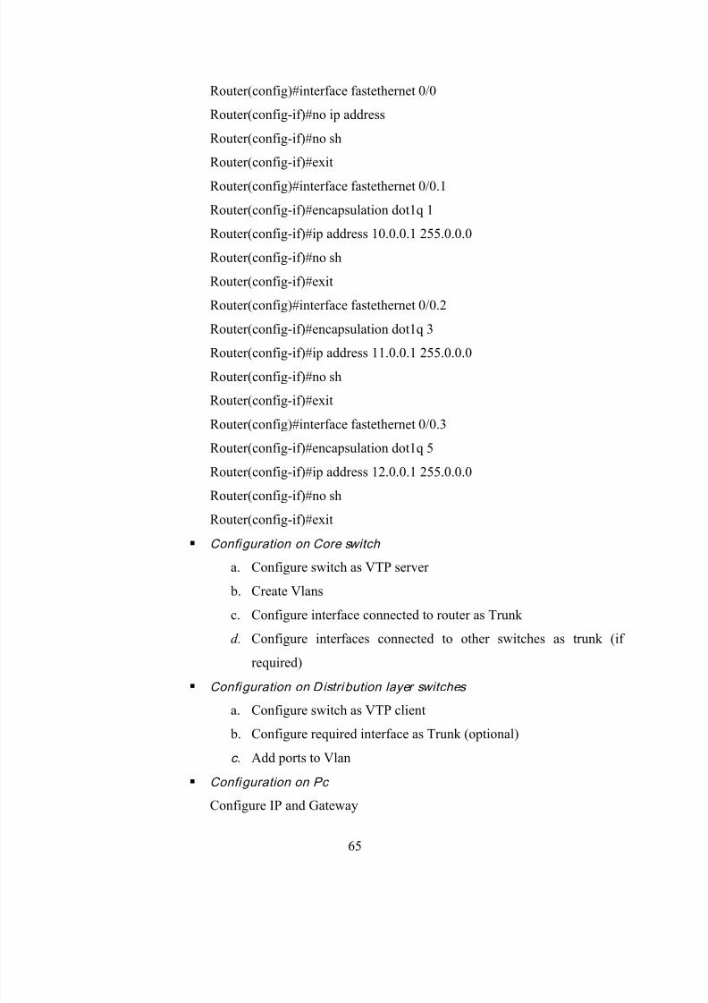
8/13/2019 Network configuration of LAN with MAN
http://slidepdf.com/reader/full/network-configuration-of-lan-with-man 65/78
65
Router(config)#interface fastethernet 0/0
Router(config-if)#no ip address
Router(config-if)#no sh
Router(config-if)#exit
Router(config)#interface fastethernet 0/0.1
Router(config-if)#encapsulation dot1q 1
Router(config-if)#ip address 10.0.0.1 255.0.0.0
Router(config-if)#no sh
Router(config-if)#exit
Router(config)#interface fastethernet 0/0.2
Router(config-if)#encapsulation dot1q 3
Router(config-if)#ip address 11.0.0.1 255.0.0.0
Router(config-if)#no sh
Router(config-if)#exit
Router(config)#interface fastethernet 0/0.3
Router(config-if)#encapsulation dot1q 5
Router(config-if)#ip address 12.0.0.1 255.0.0.0
Router(config-if)#no sh
Router(config-if)#exit
Configuration on Core switch
a. Configure switch as VTP server
b. Create Vlans
c. Configure interface connected to router as Trunk
d. Configure interfaces connected to other switches as trunk (if
required)
Configuration on Distri bution layer switches
a. Configure switch as VTP client
b. Configure required interface as Trunk (optional)
c. Add ports to Vlan
Configuration on Pc
Configure IP and Gateway
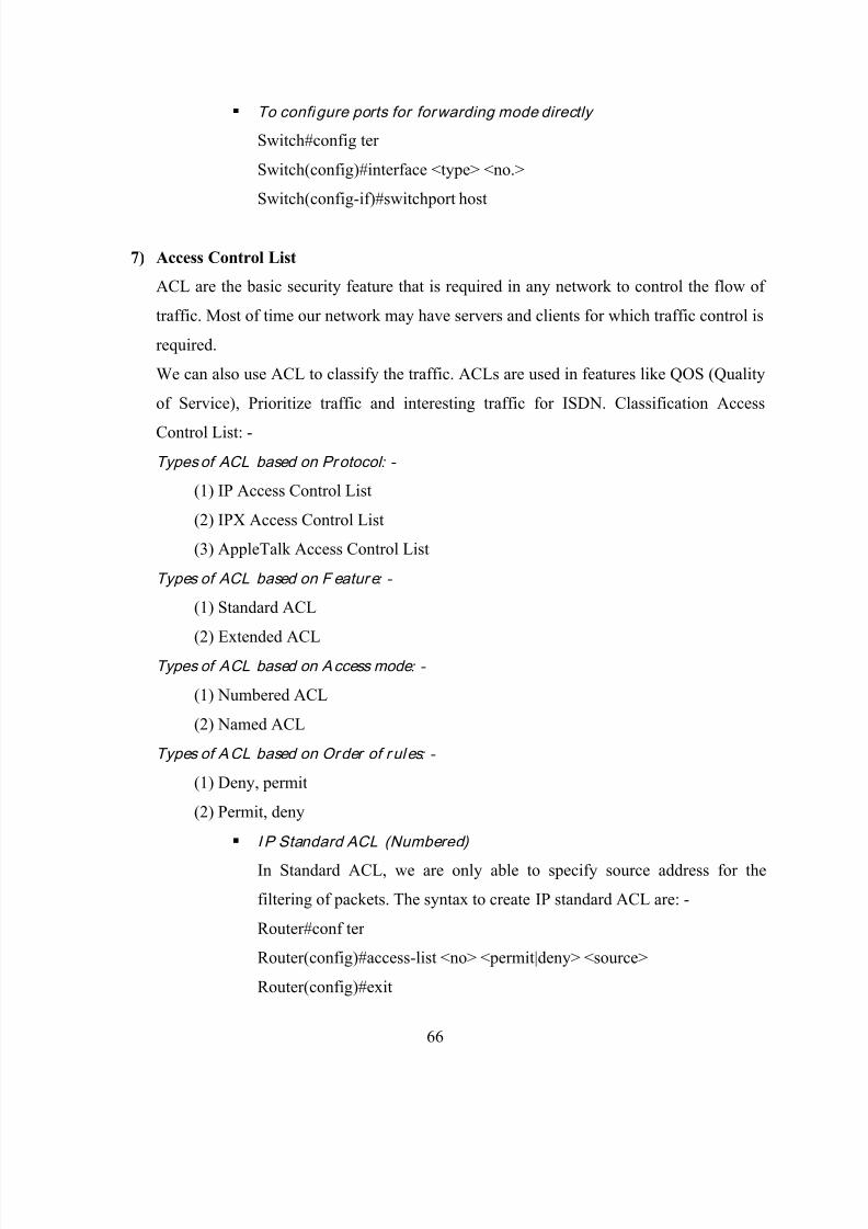
8/13/2019 Network configuration of LAN with MAN
http://slidepdf.com/reader/full/network-configuration-of-lan-with-man 66/78
66
To configure ports for forwarding mode directly
Switch#config ter
Switch(config)#interface <type> <no.>
Switch(config-if)#switchport host
7) Access Control List
ACL are the basic security feature that is required in any network to control the flow of
traffic. Most of time our network may have servers and clients for which traffic control is
required.
We can also use ACL to classify the traffic. ACLs are used in features like QOS (Quality
of Service), Prioritize traffic and interesting traffic for ISDN. Classification Access
Control List: -
Types of ACL based on Protocol : -
(1) IP Access Control List
(2) IPX Access Control List
(3) AppleTalk Access Control List
Types of ACL based on F eature : -
(1) Standard ACL
(2) Extended ACL
Types of ACL based on Access mode : -
(1) Numbered ACL
(2) Named ACL
Types of ACL based on Order of r ules : -
(1) Deny, permit
(2) Permit, deny
I P Standard ACL (Numbered)
In Standard ACL, we are only able to specify source address for the
filtering of packets. The syntax to create IP standard ACL are: -
Router#conf ter
Router(config)#access-list <no> <permit|deny> <source>
Router(config)#exit

8/13/2019 Network configuration of LAN with MAN
http://slidepdf.com/reader/full/network-configuration-of-lan-with-man 67/78
67
<source> Single pc host 192.168.10.5
192.168.10.5
192.168.10.5 0.0.0.0
N/w 200.100.100.0 0.0.0.255
Subnet 200.100.100.32 0.0.0.15
Applying ACL on interf ace
Router#conf ter
Router(config)#interface <type> <no>
Router(config-if)#ip access-group <ACL no.> <in|out>
Router(config-if)#exit
Internet
Router(config)#access-list 25 permit 192.168.10.32 0.0.0.31
Router(config)#access-list 25 permit 192.168.10.64 0.0.0.3
Router(config)#access-list 25 permit 192.168.10.68
Router(config)#access-list 25 permit 192.168.10.69
Router(config)#access-list 25 permit 192.168.10.70
Router(config)#interface serial 0
Router(config-if)#ip access-group 25 out
Router
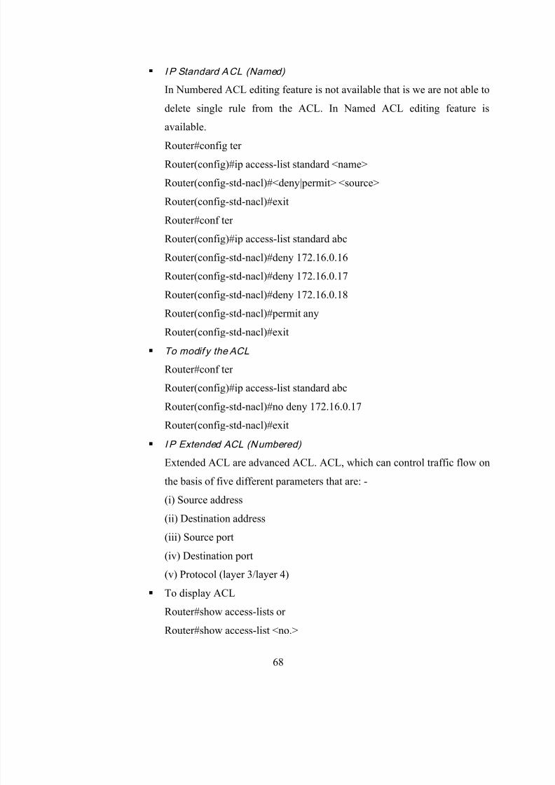
8/13/2019 Network configuration of LAN with MAN
http://slidepdf.com/reader/full/network-configuration-of-lan-with-man 68/78
68
I P Standard ACL (Named)
In Numbered ACL editing feature is not available that is we are not able to
delete single rule from the ACL. In Named ACL editing feature is
available.
Router#config ter
Router(config)#ip access-list standard <name>
Router(config-std-nacl)#<deny|permit> <source>
Router(config-std-nacl)#exit
Router#conf ter
Router(config)#ip access-list standard abc
Router(config-std-nacl)#deny 172.16.0.16
Router(config-std-nacl)#deny 172.16.0.17
Router(config-std-nacl)#deny 172.16.0.18
Router(config-std-nacl)#permit any
Router(config-std-nacl)#exit
To modif y the ACL
Router#conf ter
Router(config)#ip access-list standard abc
Router(config-std-nacl)#no deny 172.16.0.17
Router(config-std-nacl)#exit
I P Extended ACL (Numbered)
Extended ACL are advanced ACL. ACL, which can control traffic flow on
the basis of five different parameters that are: -
(i) Source address
(ii) Destination address
(iii) Source port
(iv) Destination port
(v) Protocol (layer 3/layer 4)
To display ACL
Router#show access-lists or
Router#show access-list <no.>

8/13/2019 Network configuration of LAN with MAN
http://slidepdf.com/reader/full/network-configuration-of-lan-with-man 69/78
69
To display ACL applied on interface
Router#show ip interface
Router#show ip interface <type> <no>
Router#show ip interface Ethernet 0
9) Network Address Translation
NAT is the feature that can be enable in a Router, Firewall or a Pc. With the help of
NAT, we are able to translate network layer addresses that are IP addresses of packets.
With the help of Port Address Translation, we are also able to translate port no.s present
in transport layer header.
There are two reasons due to which we use NAT: -
(1) Conserve Live IP address-On Internet, there are limited no of IP addresses. If our Pc
wants to communicate on Internet then it should have a Live IP address assigned by our
ISP. So that IP address request will depend on no. of PCs that we want to connect on
Internet. Due to this, there will be a lot of wastage in IP addresses. To reduce wastage, we
can share live IP addresses between multiple PCs with the help of NAT.
(2) NAT enhances the network security by hiding PC & devices behind NAT.
Types of NAT-
Static NAT-This NAT is used for servers in which one Live IP is directly mapped
to one Local IP. This NAT will forward on the traffic for the Live IP to the LocalPC in the n/w.
Dynamic NAT-Dynamic NAT is used for clients, which want to access Internet.
The request from multiple client IPs are translated with the Live IP obtained from
the Pool. It is also called Pool Based Dynamic NAT.
Confi guring NAT
Router#conf ter
Router(config)#int serial 0
Router(config-if)#ip nat outside
Router(config-if)#int eth 0
Router(config-if)#ip nat inside
Router(config-if)#exit
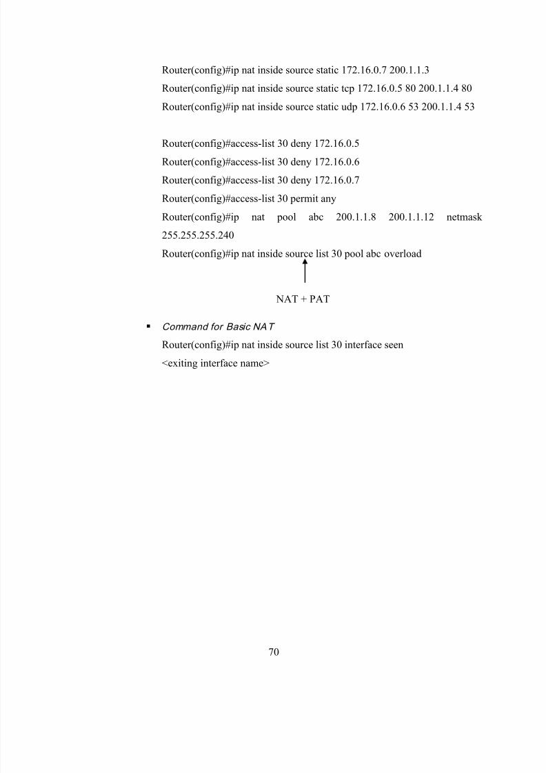
8/13/2019 Network configuration of LAN with MAN
http://slidepdf.com/reader/full/network-configuration-of-lan-with-man 70/78
70
Router(config)#ip nat inside source static 172.16.0.7 200.1.1.3
Router(config)#ip nat inside source static tcp 172.16.0.5 80 200.1.1.4 80
Router(config)#ip nat inside source static udp 172.16.0.6 53 200.1.1.4 53
Router(config)#access-list 30 deny 172.16.0.5
Router(config)#access-list 30 deny 172.16.0.6
Router(config)#access-list 30 deny 172.16.0.7
Router(config)#access-list 30 permit any
Router(config)#ip nat pool abc 200.1.1.8 200.1.1.12 netmask
255.255.255.240
Router(config)#ip nat inside source list 30 pool abc overload
NAT + PAT
Command for Basic NAT
Router(config)#ip nat inside source list 30 interface seen
<exiting interface name>

8/13/2019 Network configuration of LAN with MAN
http://slidepdf.com/reader/full/network-configuration-of-lan-with-man 71/78
71
Chapter-3
Project Methodology
Network Configuration of LAN with WAN
The project is based on the concepts of networking. It includes configuring different network
devices like Router, Switch, Bridge & connecting it with Hubs & PCs by using different types of
connecting wires by allocating the IP Addresses to all the interfaces after the subneting of
network ID. The beauty of configuring network devices is that it helps users access the network
with few constraints like allowing some to access the website but not allowing them to access the
mail server on the internet on private IP address which are otherwise excluded by internet service
provider (ISP).
We have used Routing between the various centers of a Company in different cities. Inter VLAN
technology is used to make work efficient between 2 different departments in one center.
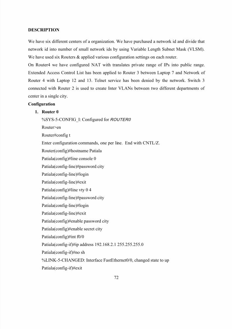
8/13/2019 Network configuration of LAN with MAN
http://slidepdf.com/reader/full/network-configuration-of-lan-with-man 72/78
72
DESCRIPTION
We have six different centers of a organization. We have purchased a network id and divide that
network id into number of small network ids by using Variable Length Subnet Mask (VLSM).
We have used six Routers & applied various configuration settings on each router.
On Router4 we have configured NAT with translates private range of IPs into public range.
Extended Access Control List has been applied to Router 3 between Laptop 7 and Network of
Router 4 with Laptop 12 and 13. Telnet service has been denied by the network. Switch 3
connected with Router 2 is used to create Inter VLANs between two different departments of
center in a single city.
Configuration
1. Router 0
%SYS-5-CONFIG_I: Configured for ROUTER0
Router>en
Router#config t
Enter configuration commands, one per line. End with CNTL/Z.
Router(config)#hostname Patiala
Patiala(config)#line console 0
Patiala(config-line)#password city
Patiala(config-line)#login
Patiala(config-line)#exit
Patiala(config)#line vty 0 4
Patiala(config-line)#password city
Patiala(config-line)#login
Patiala(config-line)#exit
Patiala(config)#enable password city
Patiala(config)#enable secret cityPatiala(config)#int f0/0
Patiala(config-if)#ip address 192.168.2.1 255.255.255.0
Patiala(config-if)#no sh
%LINK-5-CHANGED: Interface FastEthernet0/0, changed state to up
Patiala(config-if)#exit

8/13/2019 Network configuration of LAN with MAN
http://slidepdf.com/reader/full/network-configuration-of-lan-with-man 73/78
73
Patiala(config)#int s0/0/0
Patiala(config-if)# ip address 192.168.3.1 255.255.255.0
Patiala(config-if)#no sh
Patiala(config-if)#clock rate 64000
Patiala(config-if)#exit
Patiala(config)#int s0/0/1
Patiala(config-if)# ip address 192.168.4.1 255.255.255.0
Patiala(config-if)#no sh
Patiala(config-if)#clock rate 64000
Patiala(config-if)#exit
Patiala(config)#router rip
Patiala(config-router)#network 192.168.2.0
Patiala (config-router)#network 192.168.4.0
Patiala (config-router)#network 192.168.8.0
Patiala (config-router)#network 192.168.10.0
Patiala (config-router)#network 192.168.14.0
Patiala (config-router)#network 192.168.15.0
Patiala (config-router)# exit
Patiala (config)# router ospf 100
Patiala (config-router)#network 192.168.3.0 0.0.0.15 area 0
Patiala (config-router)#network 192.168.2.0 0.0.0.15 area 0
Patiala (config-router)#exit
Patiala(config)#exit
Patiala# write
2. Router 3
%SYS-5-CONFIG_I: Configured for ROUTER0
Router>en
Router#config t
Enter configuration commands, one per line. End with CNTL/Z.
Router(config)#hostname Ludhiana
Ludhiana (config)#line console 0
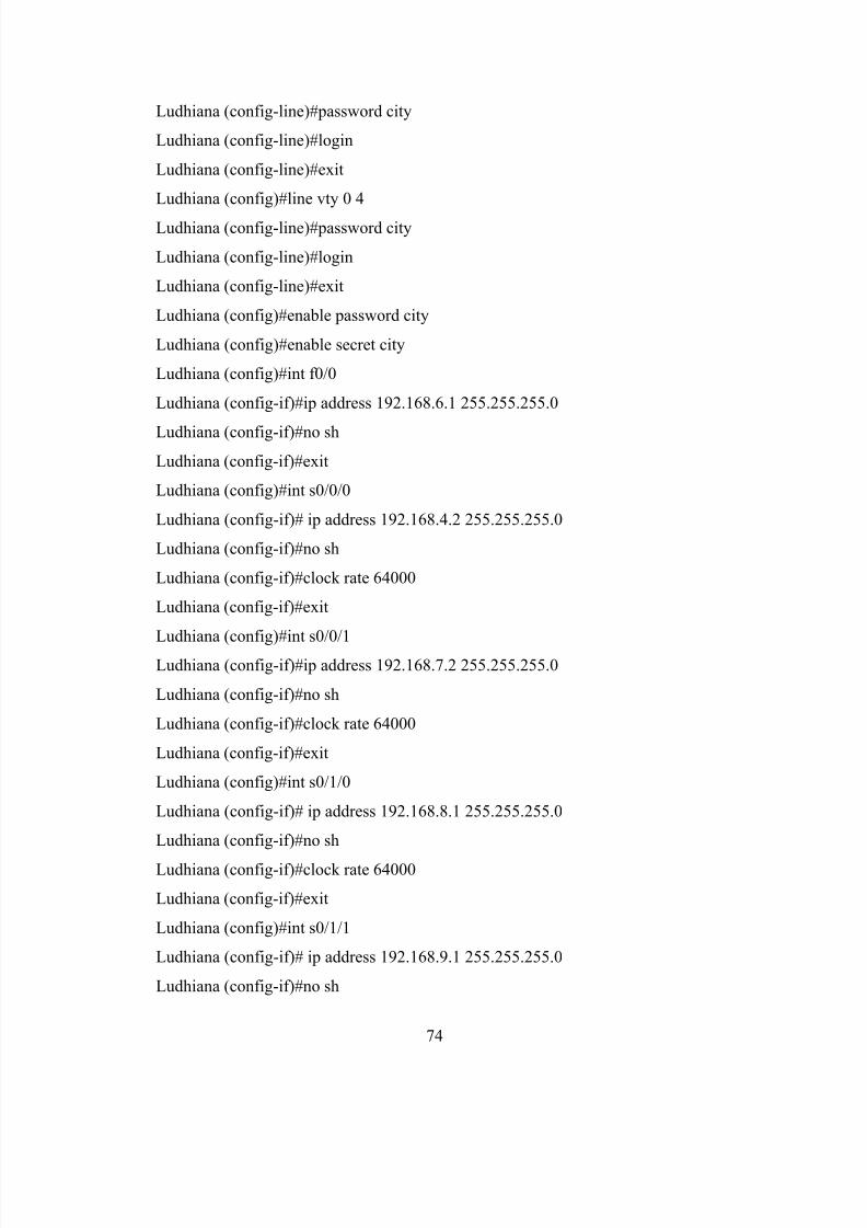
8/13/2019 Network configuration of LAN with MAN
http://slidepdf.com/reader/full/network-configuration-of-lan-with-man 74/78
74
Ludhiana (config-line)#password city
Ludhiana (config-line)#login
Ludhiana (config-line)#exit
Ludhiana (config)#line vty 0 4
Ludhiana (config-line)#password city
Ludhiana (config-line)#login
Ludhiana (config-line)#exit
Ludhiana (config)#enable password city
Ludhiana (config)#enable secret city
Ludhiana (config)#int f0/0
Ludhiana (config-if)#ip address 192.168.6.1 255.255.255.0
Ludhiana (config-if)#no sh
Ludhiana (config-if)#exit
Ludhiana (config)#int s0/0/0
Ludhiana (config-if)# ip address 192.168.4.2 255.255.255.0
Ludhiana (config-if)#no sh
Ludhiana (config-if)#clock rate 64000
Ludhiana (config-if)#exit
Ludhiana (config)#int s0/0/1
Ludhiana (config-if)#ip address 192.168.7.2 255.255.255.0
Ludhiana (config-if)#no sh
Ludhiana (config-if)#clock rate 64000
Ludhiana (config-if)#exit
Ludhiana (config)#int s0/1/0
Ludhiana (config-if)# ip address 192.168.8.1 255.255.255.0
Ludhiana (config-if)#no sh
Ludhiana (config-if)#clock rate 64000
Ludhiana (config-if)#exit
Ludhiana (config)#int s0/1/1
Ludhiana (config-if)# ip address 192.168.9.1 255.255.255.0
Ludhiana (config-if)#no sh

8/13/2019 Network configuration of LAN with MAN
http://slidepdf.com/reader/full/network-configuration-of-lan-with-man 75/78
75
Ludhiana (config-if)#clock rate 64000
Ludhiana (config-if)#exit
Ludhiana (config)# router eigrp 10
Ludhiana (config-router)# network 192.168.4.0
Ludhiana (config-router)# network 192.168.6.0
Ludhiana (config-router)#exit
Ludhiana (config)#router rip
Ludhiana (config)# network 192.168.2.0
Ludhiana (config-router)# network 192.168.4.0
Ludhiana (config-router)# network 192.168.6.0
Ludhiana (config-router)# network 192.168.7.0
Ludhiana (config-router)# network 192.168.8.0
Ludhiana (config-router)# network 192.168.9.0
Ludhiana (config-router)# network 192.168.10.0
Ludhiana (config-router)# network 192.168.11.0
Ludhiana (config-router)# network 192.168.14.0
Ludhiana (config-router)# network 192.168.15.0
Ludhiana (config-router)#exit
Ludhiana (config)#ip access-list extended city
Ludhiana (config)#deny tcp 192.168.6.4 0.0.0.1 192.168.10.1 255.255.255.0 eq 23
Ludhiana (config)# permit ip any any
Ludhiana (config)#int f0/0
Ludhiana (config-if)# ip access-group city in
Ludhiana (config-if)#exit
Ludhiana (config)#exit
Ludhiana#write
3. Router 4
%SYS-5-CONFIG_I: Configured for ROUTER4
Router>en
Router#config t
Enter configuration commands, one per line. End with CNTL/Z.

8/13/2019 Network configuration of LAN with MAN
http://slidepdf.com/reader/full/network-configuration-of-lan-with-man 76/78
76
Router(config)#hostname Jalandhar
Jalandhar (config)#line console 0
Jalandhar (config-line)#password city
Jalandhar (config-line)#login
Jalandhar (config-line)#exit
Jalandhar (config)#line vty 0 4
Jalandhar (config-line)#password city
Jalandhar (config-line)#login
Jalandhar (config-line)#exit
Jalandhar (config)#enable password city
Jalandhar (config)#enable secret city
Jalandhar (config)#int f0/0
Jalandhar (config-if)# ip address 192.168.10.1 255.255.255.0
Jalandhar (config-if)#no sh
Jalandhar (config-if)#exit
Jalandhar (config)#int f0/1
Jalandhar (config-if)#ip address 192.168.12.1 255.255.255.0
Jalandhar (config-if)#no sh
Jalandhar (config-if)#exit
Jalandhar (config)#int s0/0/0
Jalandhar (config-if)#ip address 202.20.20.1 255.255.255.0
Jalandhar (config-if)#no sh
Jalandhar (config-if)#clock rate 64000
Jalandhar (config-if)#exit
Jalandhar (config)#int s0/1/1
Jalandhar (config-if)#ip address 192.168.8.2 255.255.255.0
Jalandhar (config-if)#no sh
Jalandhar (config-if)# clock rate 64000
Jalandhar (config-if)#exit
Jalandhar (config)#router rip
Jalandhar (config-router)# network 192.168.2.0

8/13/2019 Network configuration of LAN with MAN
http://slidepdf.com/reader/full/network-configuration-of-lan-with-man 77/78
77
Jalandhar (config-router)#network 192.168.3.0
Jalandhar (config-router)#network 192.168.4.0
Jalandhar (config-router)#network 192.168.5.0
Jalandhar (config-router)#network 192.168.6.0
Jalandhar (config-router)#network 192.168.7.0
Jalandhar (config-router)#network 192.168.8.0
Jalandhar (config-router)#network 192.168.9.0
Jalandhar (config-router)#network 192.168.10.0
Jalandhar (config-router)#network 192.168.12.0
Jalandhar (config-router)#network 192.168.13.0
Jalandhar (config-router)#network 192.168.14.0
Jalandhar (config-router)#network 192.168.15.0
Jalandhar (config-router)#network 202.20.20.0
Jalandhar (config-router)#exit
Jalandhar (config)#int f0/1
Jalandhar (config-if)#ip nat inside
Jalandhar (config-if)#exit
Jalandhar (config)#int s0/0/0
Jalandhar (config-if)#ip nat outside
Jalandhar (config)#exit
Jalandhar (config)#ip access-list standard 10
Jalandhar (config)#permit 192.168.12.0 0.0.0.15
Jalandhar (config)# ip nat pool city 202.20.20.3 202.20.20.10 netmask 255.255.255.0
Jalandhar (config)# ip nat inside source list 10 pool city
Jalandhar (config)#exit
Jalandhar#write

8/13/2019 Network configuration of LAN with MAN
http://slidepdf.com/reader/full/network-configuration-of-lan-with-man 78/78