network components of the switching subsystem the switching subsystem comprises the following...
TRANSCRIPT

Network components of the Switching Subsystem
The switching Subsystem comprises the following subsystems.
MSC (Mobile Switching Centre) HLR (Home location Register) VLR (Visitor Location Register) AU (Authentification Centre) EIR (Equipment Identification Register)
Network Components of MSC
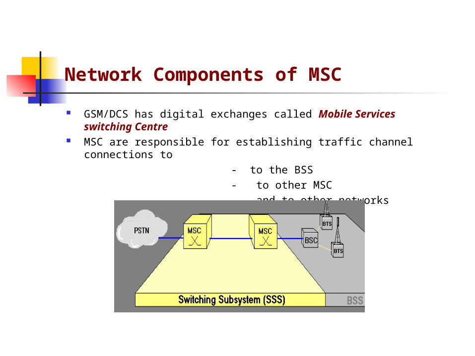
GSM/DCS has digital exchanges called Mobile Services switching Centre MSC are responsible for establishing traffic channel connections to
- to the BSS
- to other MSC
- and to other networks

The database of MSC contains the information for the routing traffic channels connections and handles the basic and supplementary services
In addition MSC performs the administration of cells and location areas
Unlike the PSTN the mobile subscriber current location determines the MSC responsible for it at that particular moment.
GSM/DCS contains a central component called the Home location Register which Administers the subscriber data.
Network Components of MSC

Network Components of MSC
The HLR is a database where the mobile subscribers are created, barred or deleted by the operator
The HLR contains all the permanent subscriber identities as well as the services (and corresponding restrictions) a mobile subscriber is authorized to use

Network Components of MSC
A great part of the HLR subscriber data is required for the connection setup and clear down
For immediate availability of the data for a call the information is temporarily stored in a further database called visitor location Register.
HLR is associated with the MSC, during the location update the subscriber data is passed from HLR to current VLR.

Network Components of MSC
VLR provides the data whenever it is needed for call handling. VLR also verifies whether the sim card is approved i.e performs the
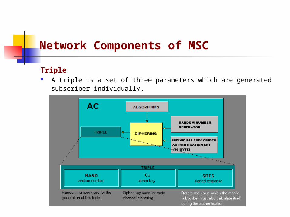
authentication VLR uses the authentication parameters called tripples, which are generated
continuously by authentication centre. and on request provided to AC The Network component AC is associated with the HLR.
Network Components of MSC
Triple A triple is a set of three parameters which are generated subscriber individually.

Network Components of MSC
The MSc also verifies whether the mobile equipment is approved or not therefore requests the (IMEI) from the MS and then sends it to the
Equipment identification register. International Mobile Equipment identity
Represents an internationally uniquely defined code which is assigned to the every mobile equipment by the manufacturer.
The IMEI consists of

Network Components of MSC

Network Components of MSC
In Equipment identification register, the IMEI of the whole mobile
equipment used are categorized into three lists
White List: contains the mobile equipment approved without restrictions.
Grey List: contains the equipment to be observed Black list: contains the unapproved equipment.
The EIR checks whether the IMEI fits into one of three list and passes the
results to MSC.
Network Components of Radio subsystem
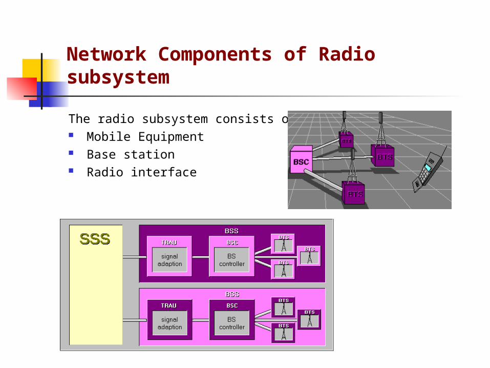
The radio subsystem consists of Mobile Equipment Base station Radio interface

The Radio Interface

The Radio interface
The GSM/DCS frequency bands

The Radio interface
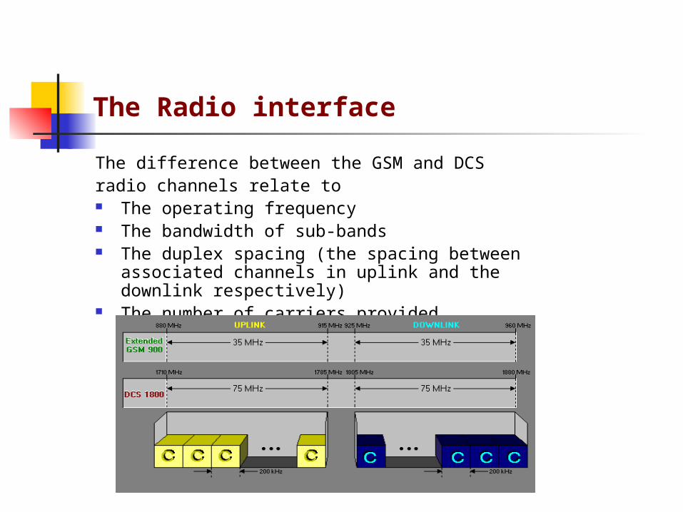
Both sub-bands uplink and down link are divided into carriers or radio frequency channels (RFC) with a bandwidth of 200khz
The carrier access procedure in the frequency range is called frequency division multiple access (FDMA)
The Radio interface
The difference between the GSM and DCS radio channels relate to The operating frequency The bandwidth of sub-bands The duplex spacing (the spacing between associated channels in
uplink and the downlink respectively) The number of carriers provided

Radio frequency channels in GSM/DCS
Depending upon the traffic volume every radio cell uses one or more RFC As the network capacity is limited the RFC has to be used several times To avoid the co-channel interference, it must be observed during the network
planning that adjacent cells use different RFC Therefore a safe distance is required between the BTS using the same RFC,
called reuse distance

Radio frequency channels in GSM/DCS
In densely populated areas, the transmission power is kept low and accordingly the cell radius is small
With a short safe distance a multiple use of the same RFC is possible.
Similar to PCM 30 system(1 link with 32 channels)
1 RFC consists of 8 channels, several mobile subscribers can access one RFC at the same time.

Radio frequency channels in GSM/DCS

Physical Channels
A physical channel is defined by a specific carrier pair (i.e., by an RFC) and by the time slot no in the TDMA frame.

Physical Channels
A physical channel can function as
traffic channel for the transmission of speech and data information Control Channel for the transmission of signaling and control
information
The generic term for traffic and control channel respectively is logical channel