netscope data acquisition cards for real-time ethernet · 65 user manual netscope data acquisition...
TRANSCRIPT
65
User Manual
netSCOPE Data Acquisition Cards for Real-Time Ethernet
PCI (NSCP-C100-RE\50)
PCI Express (NSCP-C100-RE\50E)
Low Profile PCIe (NSCP-C100-RE\70E)
Compact PCI (NSCP-C100-RE\80)
Mini PCI Express (NSCP-C100-RE\90E)
Installation, Operation and Hardware Description
Hilscher Gesellschaft für Systemautomation mbH
www.hilscher.com DOC131006UM02EN | Revision 2 | English | 2014-07 | Released | Public

Table of Contents 2/75
netSCOPE Data Acquisition Cards for Real-Time Ethernet | Installation, Operation and Hardware Description DOC131006UM02EN | Revision 2 | English | 2014-07 | Released | Public © Hilscher, 2013-2014
Table of Contents
1 INTRODUCTION.........................................................................................................5
1.1 About the User Manual ...............................................................................................5 1.1.1 List of Revisions ...................................................................................................5 1.1.2 Notes on Hardware, Software and Driver Versions .............................................6 1.1.3 Conventions in this Manual ..................................................................................7 1.1.4 Used Terminology ................................................................................................7
1.2 Contents of the netSCOPE LabVIEW DVD ................................................................8 1.2.1 Directory Structure of the netSCOPE LabVIEW DVD..........................................8 1.2.2 Documentation .....................................................................................................8
1.3 Legal Notes.................................................................................................................9 1.3.1 Copyright ..............................................................................................................9 1.3.2 Important Notes ....................................................................................................9 1.3.3 Exclusion of Liability ...........................................................................................10 1.3.4 Warranty .............................................................................................................10 1.3.5 Export Regulations .............................................................................................11 1.3.6 Registered Trademarks......................................................................................11 1.3.7 Obligation to read and understand the Manual ..................................................11 1.3.8 Hilscher Software License Agreement ...............................................................11
2 SAFETY ....................................................................................................................12
2.1 General Note ............................................................................................................12
2.2 Intended Use ............................................................................................................12
2.3 Personnel Qualification.............................................................................................12
2.4 Safety Instructions to avoid Personal Injury..............................................................13 2.4.1 Electrical Shock Hazard .....................................................................................13
2.5 Safety Instructions to avoid Property Damage .........................................................14 2.5.1 Device Destruction by exceeding allowed Supply Voltage ................................14 2.5.2 Device Destruction by exceeding allowed Signaling Voltage ............................14 2.5.3 Electrostatically sensitive Devices......................................................................15
2.6 Labeling of Safety Messages....................................................................................16
2.7 References Safety ....................................................................................................16
3 DESCRIPTIONS AND REQUIREMENTS .................................................................17
3.1 Introduction to netSCOPE ........................................................................................17
3.2 netSCOPE Data Acquisition Cards...........................................................................18
3.3 Recording and analyzing Data Traffic.......................................................................20
3.4 Hardware Requirements...........................................................................................21 3.4.1 PC.......................................................................................................................21 3.4.2 Slot for the netSCOPE Data Acquisition Cards.................................................21 3.4.3 Card Height and Panel Cutout NSCP-C100-RE\90E.........................................22 3.4.4 Power Supply and Host Interface.......................................................................23

Table of Contents 3/75
netSCOPE Data Acquisition Cards for Real-Time Ethernet | Installation, Operation and Hardware Description DOC131006UM02EN | Revision 2 | English | 2014-07 | Released | Public © Hilscher, 2013-2014
3.5 Software Requirements ............................................................................................24
4 GETTING STARTED.................................................................................................25
4.1 Notes for Installation and Operation .........................................................................25
4.2 Installation and Configuration netSCOPE Data Acquisition Card............................26
5 DEVICE DRAWINGS ................................................................................................28
5.1 netSCOPE Data Acquisition Cards PCI (NSCP-C100-RE\50) and PCI Express (NSCP-C100-RE\50E) ..............................................................................................28
5.2 netSCOPE Data Acquisition Cards Low Profile PCI Express (NSCP-C100-RE\70E)..................................................................................................................................30
5.3 netSCOPE Data Acquisition Cards Compact PCI (NSCP-C100-RE\80) ..................31
5.4 netSCOPE Data Acquisition Cards Mini PCI Express ..............................................32 5.4.1 NSCP-C100-RE\90E ..........................................................................................32
5.5 AIFX Assembly Interface Ethernet - AIFX-RE ..........................................................33
6 SOFTWARE INSTALLATION....................................................................................34
6.1 netSCOPE LabVIEW DVD Autostart Menu ..............................................................34
6.2 netANALYZER / netSCOPE Windows Device Driver ...............................................34
6.3 netSCOPE for LabVIEW Instrument Driver ..............................................................37
6.4 Microsoft Software Components...............................................................................38
6.5 Documentation..........................................................................................................39
7 HARDWARE INSTALLATION AND UNINSTALLING ...............................................40
7.1 Safety Messages on Personal Injury ........................................................................40 7.1.1 Electrical Shock Hazard .....................................................................................40
7.2 Property Damage Messages ....................................................................................41 7.2.1 Device Destruction by exceeding allowed Supply Voltage ................................41 7.2.2 Device Destruction by exceeding allowed Signaling Voltage ............................41 7.2.3 Electrostatically sensitive Devices......................................................................41
7.3 Installing netSCOPE Data Acquisition Card ............................................................42
7.4 Uninstalling netSCOPE Data Acquisition Cards ......................................................47
7.5 Microsoft Windows Power Management for netSCOPE Data Acquisition Cards PCI Express.....................................................................................................................49
8 TROUBLESHOOTING ..............................................................................................52
8.1 Instructions for Problem Solving ...............................................................................52
9 LED DESCRIPTIONS ...............................................................................................53
10 DEVICE CONNECTIONS..........................................................................................54
10.1 Ethernet Interface .....................................................................................................54 10.1.1 Ethernet Pin Assignment at the RJ45 Socket ....................................................54 10.1.2 Ethernet Connection Data ..................................................................................54
Table of Contents 4/75
netSCOPE Data Acquisition Cards for Real-Time Ethernet | Installation, Operation and Hardware Description DOC131006UM02EN | Revision 2 | English | 2014-07 | Released | Public © Hilscher, 2013-2014
10.2 Cable Connector.......................................................................................................55 10.2.1 Pin Assignment for Cable Connector Ethernet ..................................................55
10.3 Pin Assignment at the PCI Bus.................................................................................56 10.3.1 Overview.............................................................................................................56 10.3.2 References PCI Specifications...........................................................................56 10.3.3 Pin Assignment for Mini PCI Express Bus (NSCP-C100-RE\90E) ....................57
11 TECHNICAL DATA ...................................................................................................58
11.1 Technical Data netSCOPE Data Acquisition Cards..................................................58 11.1.1 NSCP-C100-RE\50.............................................................................................58 11.1.2 NSCP-C100-RE\50E ..........................................................................................60 11.1.3 NSCP-C100-RE\70E ..........................................................................................62 11.1.4 NSCP-C100-RE\80.............................................................................................64 11.1.5 NSCP-C100-RE\90E ..........................................................................................66 11.1.6 AIFX-RE .............................................................................................................68
11.2 PCI IDs netSCOPE Data Acquisition Cards on the PCI Bus ...................................69
11.3 Supported PCI-Bus Commands ...............................................................................69
12 ANNEX......................................................................................................................70
12.1 Matrix Label ..............................................................................................................70
12.2 Disposal of Waste Electronic Equipment..................................................................70
12.3 List of Figures ...........................................................................................................71
12.4 List of Tables ............................................................................................................71
12.5 Glossary....................................................................................................................73
12.6 Contacts....................................................................................................................75
Introduction 5/75
netSCOPE Data Acquisition Cards for Real-Time Ethernet | Installation, Operation and Hardware Description DOC131006UM02EN | Revision 2 | English | 2014-07 | Released | Public © Hilscher, 2013-2014
1 Introduction
1.1 About the User Manual
This user manual provides descriptions and installation instructions of
the installation of the software and
the installation, operation and hardware
of the netSCOPE data aquistion card PCI, PCI Express, Low Profile PCI Express, Compact PCI and Mini PCI Express under Windows® XP, Windows® Vista, Windows® 7 and Windows® 8, as listed subsequently.
netSCOPE data aquistion card for Real-Time Ethernet:
PCI (NSCP-C100-RE\50)
PCI Express (NSCP-C100-RE\50E)
Low Profile PCIe (NSCP-C100-RE\70E)
Compact PCI (NSCP-C100-RE\80)
Mini PCI Express (NSCP-C100-RE\90E)
for NSCP-C100-RE\90E inclusively the AIFX Assembly Interface1:
Ethernet (AIFX-RE)
for the Real-Time Ethernet system:
EtherCAT
PROFINET IO
The devices described in this manual are listed in the sections - netSCOPE Data Acquisition Cards (page 18)
The devices are described in detail in the chapters - Hardware Installation and Uninstalling (page 40), - LED Descriptions (page 53), - Device Connections (page 54) and - Technical Data (page 58).
1.1.1 List of Revisions
Index Date Chapter Revisions
1 13-10-21 All Created
2 14-07-17 All PROFINET IO protocol added.
4.1, 4.2, 7.5
Sections Notes for Installation and Operation and Installation and Configuration netSCOPE Data Acquisition Card: notice added about the required PC settings for netSCOPE data aquistion cards PCI Express (Microsoft Windows "Link State Power Management" must be shut-off). Section Microsoft Windows Power Management for netSCOPE Data Acquisition Cards PCI Express added.
Table 1: List of Revisions
1 The AIFX Assembly Interface is also named as „Detached Network Interface“.
Introduction 6/75
netSCOPE Data Acquisition Cards for Real-Time Ethernet | Installation, Operation and Hardware Description DOC131006UM02EN | Revision 2 | English | 2014-07 | Released | Public © Hilscher, 2013-2014
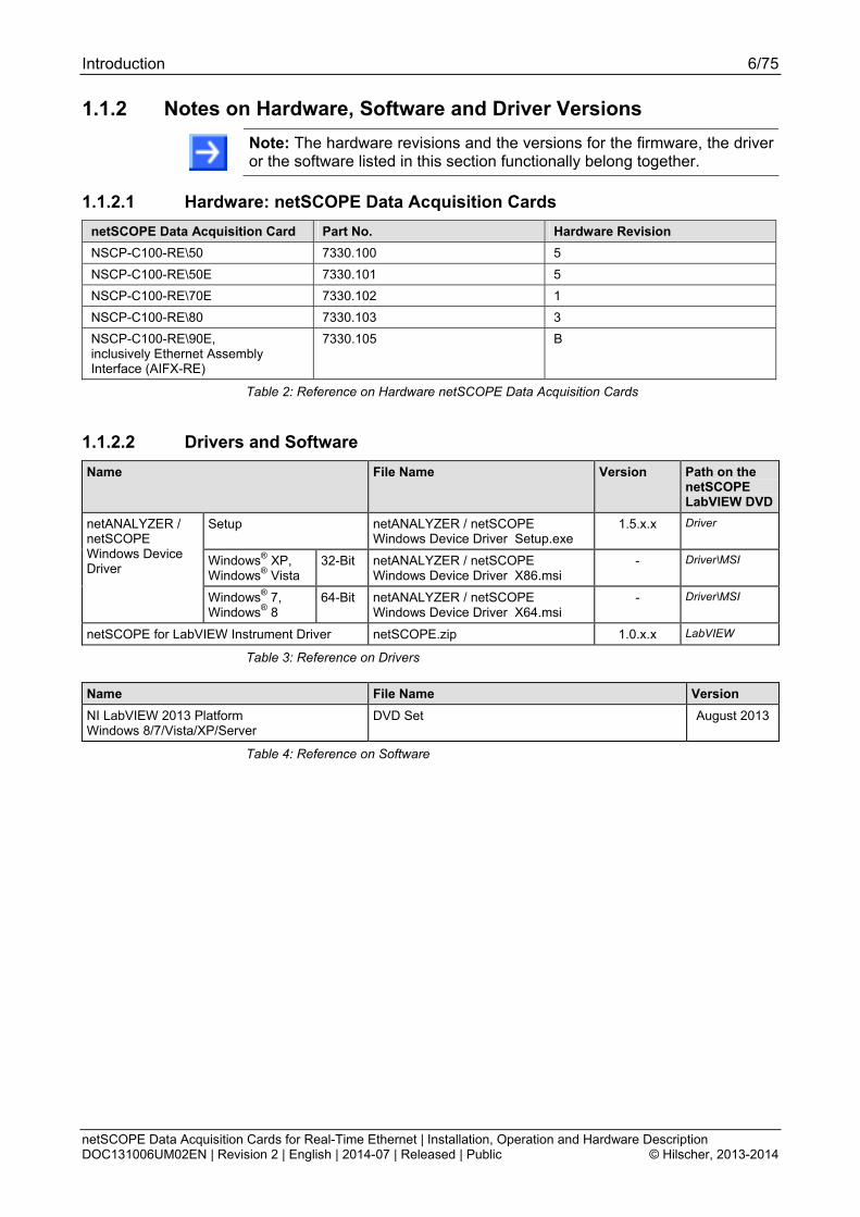
1.1.2 Notes on Hardware, Software and Driver Versions
Note: The hardware revisions and the versions for the firmware, the driver or the software listed in this section functionally belong together.
1.1.2.1 Hardware: netSCOPE Data Acquisition Cards
netSCOPE Data Acquisition Card Part No. Hardware Revision
NSCP-C100-RE\50 7330.100 5
NSCP-C100-RE\50E 7330.101 5
NSCP-C100-RE\70E 7330.102 1
NSCP-C100-RE\80 7330.103 3
NSCP-C100-RE\90E, inclusively Ethernet Assembly Interface (AIFX-RE)
7330.105 B
Table 2: Reference on Hardware netSCOPE Data Acquisition Cards
1.1.2.2 Drivers and Software
Name File Name Version Path on the netSCOPE LabVIEW DVD
Setup netANALYZER / netSCOPE Windows Device Driver Setup.exe
1.5.x.x Driver
Windows® XP, Windows® Vista
32-Bit netANALYZER / netSCOPE Windows Device Driver X86.msi
- Driver\MSI
netANALYZER / netSCOPE Windows Device Driver
Windows® 7, Windows® 8
64-Bit netANALYZER / netSCOPE Windows Device Driver X64.msi
- Driver\MSI
netSCOPE for LabVIEW Instrument Driver netSCOPE.zip 1.0.x.x LabVIEW
Table 3: Reference on Drivers
Name File Name Version
NI LabVIEW 2013 Platform Windows 8/7/Vista/XP/Server
DVD Set August 2013
Table 4: Reference on Software

Introduction 7/75
netSCOPE Data Acquisition Cards for Real-Time Ethernet | Installation, Operation and Hardware Description DOC131006UM02EN | Revision 2 | English | 2014-07 | Released | Public © Hilscher, 2013-2014
1.1.3 Conventions in this Manual
Notes, operation instructions and results of operation steps are marked as follows:
Notes
Important: <important note you must follow to avoid malfunction>
Note: <general note>
<note, where to find further information>
Operation Instructions
1. <instruction>
2. <instruction>
or
<instruction>
Results
<result>
Safety Messages
The labeling of safety messages is explained in the chapter Safety.
1.1.4 Used Terminology
netSCOPE data acquisition card
Hilscher netSCOPE data acquisition card based on the netX technology.
NSCP-C100-RE\50 Example for the type name of a netSCOPE data aquistion card for Real-Time Ethernet.
Introduction 8/75
netSCOPE Data Acquisition Cards for Real-Time Ethernet | Installation, Operation and Hardware Description DOC131006UM02EN | Revision 2 | English | 2014-07 | Released | Public © Hilscher, 2013-2014
1.2 Contents of the netSCOPE LabVIEW DVD
The netSCOPE LabVIEW DVD for the netSCOPE data aquistion card contains:
The netANALYZER / netSCOPE Windows Device Driver file for 32-bit and for 64-bit
netSCOPE for LabVIEW Instrument Driver
The documentation
1. netSCOPE User Manual (this document)
2. netSCOPE Operating Instruction Manual
1.2.1 Directory Structure of the netSCOPE LabVIEW DVD
Directory Name Description
Root Directory Flash Animation (netSCOPE-for-LabVIEW.exe)
Documentation Documentation in the Acrobat® Reader Format (PDF), Adobe® Reader Installation
Driver netANALYZER / netSCOPE Windows Device Driver for 32-bit (for Windows® XP and Windows® Vista) respectively for 64-bit (for Windows® 7 and Windows® 8)
netSCOPE for LabVIEW Instrument Driver
fscommand Help files for the installation program.
LabVIEW netSCOPE.zip with the LabVIEW instrument driver
Table 5: Directory Structure of the netSCOPE LabVIEW DVD
1.2.2 Documentation
The following documentation overview gives information, for which items you can find further information in which manual. Available on the netSCOPE LabVIEW DVD
Document Type Title Document ID File Name
User Manual netSCOPE Data Acquisition Cards for Real-Time Ethernet [ …] Installation, Operation and Hardware Description
DOC131006UMXXEN netSCOPE Data Acquisition Cards for RTE UM xx EN.pdf
Operating Instruction Manual
netSCOPE, VIs for LabVIEW
DOC131005OIXXEN netSCOPE for LabVIEW OI xx EN.pdf
Table 6: Documentations netSCOPE LabVIEW DVD
These documents are available on the DVD delivered with the device underneath the directory Documentation, in Adobe Acrobat® Reader format (PDF) or you can download the latest edition of a manual from the website www.hilscher.com under Support > Downloads > Manuals or under Products directly with the information about your product.

Introduction 9/75
netSCOPE Data Acquisition Cards for Real-Time Ethernet | Installation, Operation and Hardware Description DOC131006UM02EN | Revision 2 | English | 2014-07 | Released | Public © Hilscher, 2013-2014
1.3 Legal Notes
1.3.1 Copyright
© Hilscher, 2013-2014, Hilscher Gesellschaft für Systemautomation mbH
All rights reserved.
The images, photographs and texts in the accompanying material (user manual, accompanying texts, documentation, etc.) are protected by German and international copyright law as well as international trade and protection provisions. You are not authorized to duplicate these in whole or in part using technical or mechanical methods (printing, photocopying or other methods), to manipulate or transfer using electronic systems without prior written consent. You are not permitted to make changes to copyright notices, markings, trademarks or ownership declarations. The included diagrams do not take the patent situation into account. The company names and product descriptions included in this document may be trademarks or brands of the respective owners and may be trademarked or patented. Any form of further use requires the explicit consent of the respective rights owner.
1.3.2 Important Notes
The user manual, accompanying texts and the documentation were created for the use of the products by qualified experts, however, errors cannot be ruled out. For this reason, no guarantee can be made and neither juristic responsibility for erroneous information nor any liability can be assumed. Descriptions, accompanying texts and documentation included in the user manual do not present a guarantee nor any information about proper use as stipulated in the contract or a warranted feature. It cannot be ruled out that the user manual, the accompanying texts and the documentation do not correspond exactly to the described features, standards or other data of the delivered product. No warranty or guarantee regarding the correctness or accuracy of the information is assumed.
We reserve the right to change our products and their specification as well as related user manuals, accompanying texts and documentation at all times and without advance notice, without obligation to report the change. Changes will be included in future manuals and do not constitute any obligations. There is no entitlement to revisions of delivered documents. The manual delivered with the product applies.
Hilscher Gesellschaft für Systemautomation mbH is not liable under any circumstances for direct, indirect, incidental or follow-on damage or loss of earnings resulting from the use of the information contained in this publication.
Introduction 10/75
netSCOPE Data Acquisition Cards for Real-Time Ethernet | Installation, Operation and Hardware Description DOC131006UM02EN | Revision 2 | English | 2014-07 | Released | Public © Hilscher, 2013-2014
1.3.3 Exclusion of Liability
The software was produced and tested with utmost care by Hilscher Gesellschaft für Systemautomation mbH and is made available as is. No warranty can be assumed for the performance and flawlessness of the software for all usage conditions and cases and for the results produced when utilized by the user. Liability for any damages that may result from the use of the hardware or software or related documents, is limited to cases of intent or grossly negligent violation of significant contractual obligations. Indemnity claims for the violation of significant contractual obligations are limited to damages that are foreseeable and typical for this type of contract.
It is strictly prohibited to use the software in the following areas:
for military purposes or in weapon systems;
for the design, construction, maintenance or operation of nuclear facilities;
in air traffic control systems, air traffic or air traffic communication systems;
in life support systems;
in systems in which failures in the software could lead to personal injury or injuries leading to death.
We inform you that the software was not developed for use in dangerous environments requiring fail-proof control mechanisms. Use of the software in such an environment occurs at your own risk. No liability is assumed for damages or losses due to unauthorized use.
1.3.4 Warranty
Although the hardware and software was developed with utmost care and tested intensively, Hilscher Gesellschaft für Systemautomation mbH does not guarantee its suitability for any purpose not confirmed in writing. It cannot be guaranteed that the hardware and software will meet your requirements, that the use of the software operates without interruption and that the software is free of errors. No guarantee is made regarding infringements, violations of patents, rights of ownership or the freedom from interference by third parties. No additional guarantees or assurances are made regarding marketability, freedom of defect of title, integration or usability for certain purposes unless they are required in accordance with the law and cannot be limited. Warranty claims are limited to the right to claim rectification.

Introduction 11/75
netSCOPE Data Acquisition Cards for Real-Time Ethernet | Installation, Operation and Hardware Description DOC131006UM02EN | Revision 2 | English | 2014-07 | Released | Public © Hilscher, 2013-2014
1.3.5 Export Regulations
The delivered product (including the technical data) is subject to export or import laws as well as the associated regulations of different counters, in particular those of Germany and the USA. The software may not be exported to countries where this is prohibited by the United States Export Administration Act and its additional provisions. You are obligated to comply with the regulations at your personal responsibility. We wish to inform you that you may require permission from state authorities to export, re-export or import the product.
1.3.6 Registered Trademarks
Windows® XP, Windows® Vista, Windows® 7 and Windows® 8 are registered trademarks of Microsoft Corporation.
Adobe-Acrobat® is a registered trademark of the Adobe Systems Incorporated.
EtherCAT® is a registered trademark and a patented technology of Beckhoff Automation GmbH, Verl, Germany, formerly Elektro Beckhoff GmbH.
PROFINET® is a registered trademark of PROFIBUS & PROFINET International (PI), Karlsruhe.
LabVIEW is a graphical programming system from National Instruments.
PCI™, PCI EXPRESS® and PCIe® or MINI PCI™ are trademarks or registered trademarks of the Peripheral Component Interconnect Special Interest Group (PCI-SIG).
CompactPCI™ is a trademark of the PCI Industrial Manufacturers Group (PICMG).
All other mentioned trademarks are property of their respective legal owners.
1.3.7 Obligation to read and understand the Manual
Important!
To avoid personal injury and to avoid property damage to your system or to your netSCOPE data aquistion card, you must read and understand all instructions in the manual and all accompanying texts to your netSCOPE data aquistion card, before installing and operating your netSCOPE data aquistion card.
First read the Safety Instructions in the safety chapter.
Obey to all Safety Messages in the manual.
Keep the product DVD providing the product manuals.
1.3.8 Hilscher Software License Agreement
When you install the Hilscher software you are asked to read the Hilscher Software License Agreement and explain your acceptance to it.
Safety 12/75
netSCOPE Data Acquisition Cards for Real-Time Ethernet | Installation, Operation and Hardware Description DOC131006UM02EN | Revision 2 | English | 2014-07 | Released | Public © Hilscher, 2013-2014
2 Safety
2.1 General Note
The documentation in the form of a user manual, an operating instruction manual or other manual types, as well as the accompanying texts have been created for the use of the products by educated personnel. When using the products, all Safety Messages, Safety Messages, Property Damage Messages and all valid legal regulations have to be obeyed. Technical knowledge is presumed. The user has to assure that all legal regulations are obeyed.
2.2 Intended Use
The netSCOPE data aquistion card described in this User Manual each work as a passive Ethernet analyzer in RT-Ethernet systems. The netSCOPE data aquistion card analyze the data in a communication link and capture the incoming Ethernet frames.
Name netSCOPE Data Acquisition Card
netSCOPE data acquisition card PCI for Real-Time Ethernet NSCP-C100-RE\50
netSCOPE data acquisition card PCI Express for Real-Time Ethernet NSCP-C100-RE\50E
netSCOPE data acquisition card Low Profile PCIe for Real-Time Ethernet NSCP-C100-RE\70E
netSCOPE data acquisition card Compact PCI for Real-Time Ethernet NSCP-C100-RE\80
netSCOPE data acquisition card Mini PCI for Express Real-Time Ethernet NSCP-C100-RE\90E, inclusively Ethernet Assembly Interface (AIFX-RE)
Table 7: netSCOPE Data Acquisition Cards
If the netSCOPE data aquistion cards are used outside of the scope described in this user manual, an error free function can not be guaranteed.
2.3 Personnel Qualification
The netSCOPE data aquistion card must only be installed, configured and removed by qualified personnel. Job-specific technical skills for people professionally working with electricity must be present concerning the following topics:
Safety and health at work
Mounting and connecting of electrical equipment
Measurement and Analysis of electrical functions and systems
Evaluation of the safety of electrical systems and equipment
Installing and Configuring IT systems

Safety 13/75
netSCOPE Data Acquisition Cards for Real-Time Ethernet | Installation, Operation and Hardware Description DOC131006UM02EN | Revision 2 | English | 2014-07 | Released | Public © Hilscher, 2013-2014
2.4 Safety Instructions to avoid Personal Injury
To ensure your own personal safety and to avoid personal injury, you necessarily must read, understand and follow the following safety instructions and safety messages in this manual about danger causing personal injury, before you install and operate your netSCOPE data aquistion card.
2.4.1 Electrical Shock Hazard
The danger of a lethal electrical shock caused by parts with more than 50V may occur if you open the PC cabinet to install the netSCOPE data aquistion card.
HAZARDOUS VOLTAGE is present inside of the PC or of the connec-ting device, into which the netSCOPE data aquistion card is integrated. Strictly obey to all safety rules provided by the device’s manufacturer in the documentation!
First disconnect the power plug of the PC or of the connecting device, before you open the cabinet.
Make sure, that the power supply is off at the PC or at the connecting device.
Open the PC cabinet and install or remove the netSCOPE data aquistion card only after disconnecting power.
An electrical shock is the result of a current flowing through the human body. The resulting effect depends on the intensity and duration of the current and on its path through the body. Currents in the range of approximately ½ mA can cause effects in persons with good health, and indirectly cause injuries resulting from startle responses. Higher currents can cause more direct effects, such as burns, muscle spasms, or ventricular fibrillation.
In dry conditions permanent voltages up to approximately 42.4 V peak or 60 V are not considered as dangerous if the contact area is equivalent to the size of a human hand.
Reference Safety [S2]
Safety 14/75
netSCOPE Data Acquisition Cards for Real-Time Ethernet | Installation, Operation and Hardware Description DOC131006UM02EN | Revision 2 | English | 2014-07 | Released | Public © Hilscher, 2013-2014
2.5 Safety Instructions to avoid Property Damage
To avoid property damage respectively device destruction to the netSCOPE data aquistion card and to your system, you necessarily must read, understand and follow the following safety instructions and safety messages in this manual about danger causing property damage, before you install and operate your netSCOPE data aquistion card.
2.5.1 Device Destruction by exceeding allowed Supply Voltage
To avoid device destruction due to high supply voltage to your netSCOPE data aquistion card, you must observe the following instructions. These instructions apply to all netSCOPE data aquistion cards described in this manual.
The netSCOPE data aquistion card may only be operated with the specified supply voltage. Make sure that the limits of the allowed range for the supply voltage are not exceeded. A supply voltage above the upper limit can cause severe damage to the netSCOPE data aquistion card! A supply voltage below the lower limit can cause malfunction in the netSCOPE data aquistion card. The allowed range for the supply voltage is defined by the tolerances specified in this manual.
For the netSCOPE data aquistion cards listed hereafter adhere specifically: The netSCOPE data aquistion card
NSCP-C100-RE\50,
NSCP-C100-RE\50E,
NSCP-C100-RE\70E,
NSCP-C100-RE\80,
NSCP-C100-RE\90E
may not be powered by a 5V supply voltage! The netSCOPE data aquistion card may only be powered by a 3.3 V dc ±5 % supply voltage.
The data on the mandatory supply voltage for the netSCOPE data aquistion cards described in this manual you find in section Power Supply and Host Interface on page 23. There the required and permitted supply voltage is provided by device type inclusively the permitted tolerance range.
2.5.2 Device Destruction by exceeding allowed Signaling Voltage
To avoid device destruction due to high signal voltage to your netSCOPE data aquistion card, you must observe the following instructions. These instructions apply to all netSCOPE data aquistion cards described in this manual.
All I/O signal pins at the netSCOPE data aquistion card tolerate only the specified signaling voltage!
Operating of your netSCOPE data aquistion card with a signaling voltage other than the specified signaling voltage may lead to severe damage to the netSCOPE data aquistion card!
Safety 15/75
netSCOPE Data Acquisition Cards for Real-Time Ethernet | Installation, Operation and Hardware Description DOC131006UM02EN | Revision 2 | English | 2014-07 | Released | Public © Hilscher, 2013-2014
The data on the mandatory signaling voltage for the netSCOPE data aquistion cards described in this manual you find in the section Power Supply and Host Interface on page 23.There the required and permitted signaling voltage is provided by device type.
2.5.3 Electrostatically sensitive Devices
This equipment is sensitive to electrostatic discharge, which cause internal damage and affect normal operation. Therefore adhere to the necessary safety precautions for components that are vulnerable with electrostatic discharge if you install or replace your device. Follow the guidelines listed hereafter when you handle this equipment:
Touch a grounded object to discharge potential static.
Wear an approved grounding wriststrap.
Do not touch connectors or pins on the netSCOPE data aquistion card.
Do not touch circuit components inside the equipment.
If available, use a static-safe workstation.
When not in use, store the equipment in appropriate static-safe packaging.
Reference Safety [S3]
Safety 16/75
netSCOPE Data Acquisition Cards for Real-Time Ethernet | Installation, Operation and Hardware Description DOC131006UM02EN | Revision 2 | English | 2014-07 | Released | Public © Hilscher, 2013-2014
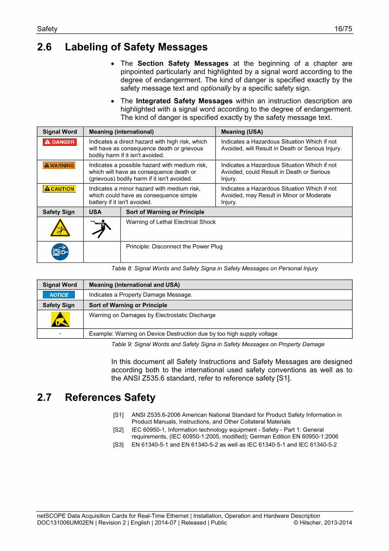
2.6 Labeling of Safety Messages
The Section Safety Messages at the beginning of a chapter are pinpointed particularly and highlighted by a signal word according to the degree of endangerment. The kind of danger is specified exactly by the safety message text and optionally by a specific safety sign.
The Integrated Safety Messages within an instruction description are highlighted with a signal word according to the degree of endangerment. The kind of danger is specified exactly by the safety message text.
Signal Word Meaning (international) Meaning (USA)
Indicates a direct hazard with high risk, which will have as consequence death or grievous bodily harm if it isn't avoided.
Indicates a Hazardous Situation Which if not Avoided, will Result in Death or Serious Injury.
Indicates a possible hazard with medium risk, which will have as consequence death or (grievous) bodily harm if it isn't avoided.
Indicates a Hazardous Situation Which if not Avoided, could Result in Death or Serious Injury.
Indicates a minor hazard with medium risk, which could have as consequence simple battery if it isn't avoided.
Indicates a Hazardous Situation Which if not Avoided, may Result in Minor or Moderate Injury.
Safety Sign USA Sort of Warning or Principle
Warning of Lethal Electrical Shock
Principle: Disconnect the Power Plug
Table 8: Signal Words and Safety Signa in Safety Messages on Personal Injury
Signal Word Meaning (international and USA)
Indicates a Property Damage Message.
Safety Sign Sort of Warning or Principle
Warning on Damages by Electrostatic Discharge
- Example: Warning on Device Destruction due by too high supply voltage
Table 9: Signal Words and Safety Signa in Safety Messages on Property Damage
In this document all Safety Instructions and Safety Messages are designed according both to the international used safety conventions as well as to the ANSI Z535.6 standard, refer to reference safety [S1].
2.7 References Safety
[S1] ANSI Z535.6-2006 American National Standard for Product Safety Information in Product Manuals, Instructions, and Other Collateral Materials
[S2] IEC 60950-1, Information technology equipment - Safety - Part 1: General requirements, (IEC 60950-1:2005, modified); German Edition EN 60950-1:2006
[S3] EN 61340-5-1 and EN 61340-5-2 as well as IEC 61340-5-1 and IEC 61340-5-2
Descriptions and Requirements 17/75
netSCOPE Data Acquisition Cards for Real-Time Ethernet | Installation, Operation and Hardware Description DOC131006UM02EN | Revision 2 | English | 2014-07 | Released | Public © Hilscher, 2013-2014
3 Descriptions and Requirements
3.1 Introduction to netSCOPE
The main characteristics of the netSCOPE data aquistion cards are:
Process monitoring
Process documentation
Data acquisition of process values directly from the network
No additional signal wiring
No modification in PLC necessary
You can use the netSCOPE data aquistion cards to record and analyze data of Ethernet based automation network or its components conforming to the Ethernet II IEEE 802.3 specification.
For visualization, archiving or machine diagnosis purposes, not even network telegrams but process values are captured from the network. The netSCOPE data aquistion card is connected to the automation network as a purely passive node.
Process values are converted to be displayed in LabVIEW for analyzing purposes without changing your PLC program at all. All data from the network is recorded with precision timestamp. All collected process data is being recorded in a way that it is associated to a certain network cycle ("communication cycle accurate"). At any point of time the record is complete, allowing examination of information like measurements, status and control values by going back in time to find out what had happen in your process.
A detailed description how to use the netSCOPE instrument driver in LabVIEW you find in the Operating Instruction Manual netSCOPE, VIs for LabVIEW.

Descriptions and Requirements 18/75
netSCOPE Data Acquisition Cards for Real-Time Ethernet | Installation, Operation and Hardware Description DOC131006UM02EN | Revision 2 | English | 2014-07 | Released | Public © Hilscher, 2013-2014
3.2 netSCOPE Data Acquisition Cards
netSCOPE Data Acquisition Cards with integrated Ethernet Interface
netSCOPE Data Acquisition Card
Description
NSCP-C100-RE\50
netSCOPE data acquisition card PCI for Real-Time Ethernet
NSCP-C100-RE\50E
netSCOPE data acquisition card PCI Express for Real-Time Ethernet
NSCP-C100-RE\70E
netSCOPE data acquisition card Low Profile PCIe for Real-Time Ethernet

Descriptions and Requirements 19/75
netSCOPE Data Acquisition Cards for Real-Time Ethernet | Installation, Operation and Hardware Description DOC131006UM02EN | Revision 2 | English | 2014-07 | Released | Public © Hilscher, 2013-2014
netSCOPE Data Acquisition Card
Description
NSCP-C100-RE\80
netSCOPE data acquisition card Compact PCI for Real-Time Ethernet
Table 10: netSCOPE Data Acquisition Cards with integrated Ethernet Interface
The netSCOPE data aquistion cards NSCP-C100-RE\50, NSCP-C100-RE\50E, NSCP-C100-RE\70E and NSCP-C100-RE\80 provide an integrated Ethernet interface.
netSCOPE Data Acquisition Card with AIFX Assembly Interface Ethernet
netSCOPE Data Acquisition Card
Description
NSCP-C100-RE\90E
netSCOPE data acquisition card Mini PCI Express for Real-Time Ethernet
inclusively Ethernet Assembly Interface AIFX-RE (with Ethernet interface)
Table 11: netSCOPE Data Acquisition Card with AIFX Assembly Interface Ethernet
The netSCOPE data aquistion card NSCP-C100-RE\90E is composed of a basic card and an assembly interface AIFX. The basic card NSCP-C100-RE\90E is equipped with a Cable Connector Ethernet, to connect the Ethernet assembly interface (AIFX-RE).
Important! Operating the netSCOPE data aquistion card Mini PCI Express NSCP-C100-RE\90E requires proper connection of the Ethernet assembly interface (AIFX-RE) to the basic card!
Note: The device height and the power input of the netSCOPE data aquistion card NSCP-C100-RE\90E do not comply with the standard specifications.
Descriptions and Requirements 20/75
netSCOPE Data Acquisition Cards for Real-Time Ethernet | Installation, Operation and Hardware Description DOC131006UM02EN | Revision 2 | English | 2014-07 | Released | Public © Hilscher, 2013-2014
3.3 Recording and analyzing Data Traffic
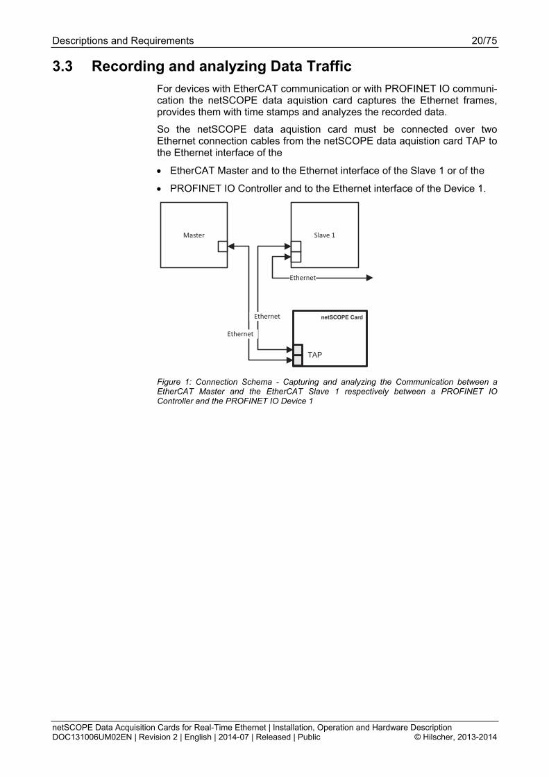
For devices with EtherCAT communication or with PROFINET IO communi-cation the netSCOPE data aquistion card captures the Ethernet frames, provides them with time stamps and analyzes the recorded data.
So the netSCOPE data aquistion card must be connected over two Ethernet connection cables from the netSCOPE data aquistion card TAP to the Ethernet interface of the
EtherCAT Master and to the Ethernet interface of the Slave 1 or of the
PROFINET IO Controller and to the Ethernet interface of the Device 1.
Master Slave 1
netSCOPE Card
TAP
Ethernet
Ethernet
Ethernet
Figure 1: Connection Schema - Capturing and analyzing the Communication between a EtherCAT Master and the EtherCAT Slave 1 respectively between a PROFINET IO Controller and the PROFINET IO Device 1

Descriptions and Requirements 21/75
netSCOPE Data Acquisition Cards for Real-Time Ethernet | Installation, Operation and Hardware Description DOC131006UM02EN | Revision 2 | English | 2014-07 | Released | Public © Hilscher, 2013-2014
3.4 Hardware Requirements
3.4.1 PC
PC with the following specification:
Intel compatible CPU, approx. 2 GHz or faster
1 GB RAM or more
1 PCI slot (refer to section Slot for the netSCOPE Data Acquisition Cards page 21)
Note: The netSCOPE data aquistion card NSCP-C100-RE\90E can be used together with main boards according to any earlier revision (1.1 and 1.2) of the Mini PCI Express specification [bus spec 6], as well as to the latest revision (2.0).
For the reference for [bus spec 6] for the bus specification for Mini PCI Express refer to section References PCI Specifications on page 56 of this manual.
3.4.2 Slot for the netSCOPE Data Acquisition Cards
PC with slot (3.3 V) for netSCOPE data aquistion cards PCI, PCI Express, Low Profile PCI Express, Compact PCI and Mini PCI Express:
netSCOPE Data Acquisition Cards
PCI Bus [Pins]
Slot
NSCP-C100-RE\50 124 PCI slot (3.3 V)
NSCP-C100-RE\50E, NSCP-C100-RE\70E
36 PCI Express x1 slot (3.3 V),
x12 = One Lane [bus spec 3]
NSCP-C100-RE\80 110 Compact PCI Slot (3.3 V)
NSCP-C100-RE\90E 52 PCI Express Mini System Connector (3.3 V), X1/X23 = One Lane
Note: As the basic card NSCP-C100-RE\90E can be inserted correctly into the Mini PCI Express slot, the element height in the Mini PCI Express slot of the connecting device must meet to the standard specifications.
Table 12: Slot for the netSCOPE Data Acquisition Cards
2 The term "x1" refers to the convention of the PCI Express specifications [bus spec 3] to the number of lanes in the slot. 3 X1, X2 corresponds to the Hilscher convention for „interface“ on the top or the bottom side of the netSCOPE Data Acquisition Card.
Descriptions and Requirements 22/75
netSCOPE Data Acquisition Cards for Real-Time Ethernet | Installation, Operation and Hardware Description DOC131006UM02EN | Revision 2 | English | 2014-07 | Released | Public © Hilscher, 2013-2014
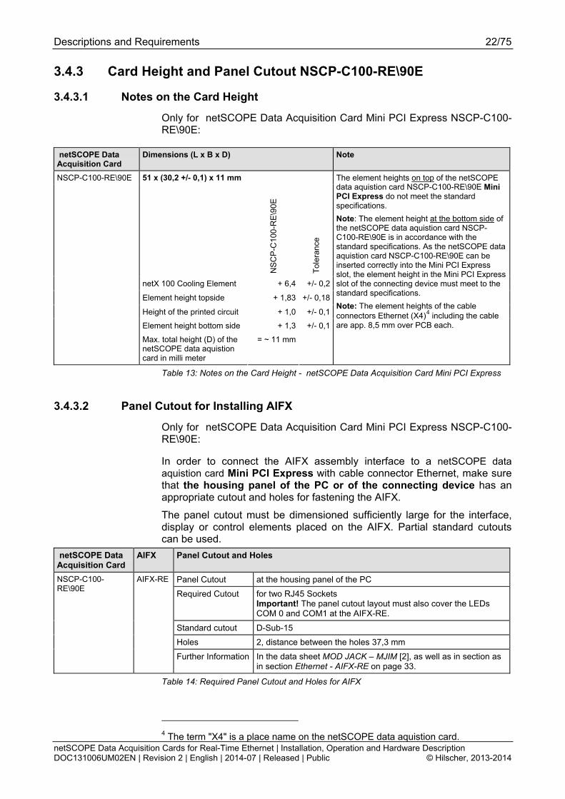
3.4.3 Card Height and Panel Cutout NSCP-C100-RE\90E
3.4.3.1 Notes on the Card Height
Only for netSCOPE Data Acquisition Card Mini PCI Express NSCP-C100-RE\90E:
netSCOPE Data Acquisition Card
Dimensions (L x B x D) Note
51 x (30,2 +/- 0,1) x 11 mm
NS
CP
-C10
0-R
E\9
0E
Tol
eran
ce
netX 100 Cooling Element + 6,4 +/- 0,2
Element height topside + 1,83 +/- 0,18
Height of the printed circuit + 1,0 +/- 0,1
Element height bottom side + 1,3 +/- 0,1
NSCP-C100-RE\90E
Max. total height (D) of the netSCOPE data aquistion card in milli meter
= ~ 11 mm
The element heights on top of the netSCOPE data aquistion card NSCP-C100-RE\90E Mini PCI Express do not meet the standard specifications.
Note: The element height at the bottom side of the netSCOPE data aquistion card NSCP-C100-RE\90E is in accordance with the standard specifications. As the netSCOPE data aquistion card NSCP-C100-RE\90E can be inserted correctly into the Mini PCI Express slot, the element height in the Mini PCI Express slot of the connecting device must meet to the standard specifications.
Note: The element heights of the cable connectors Ethernet (X4)4 including the cable are app. 8,5 mm over PCB each.
Table 13: Notes on the Card Height - netSCOPE Data Acquisition Card Mini PCI Express
3.4.3.2 Panel Cutout for Installing AIFX
Only for netSCOPE Data Acquisition Card Mini PCI Express NSCP-C100-RE\90E:
In order to connect the AIFX assembly interface to a netSCOPE data aquistion card Mini PCI Express with cable connector Ethernet, make sure that the housing panel of the PC or of the connecting device has an appropriate cutout and holes for fastening the AIFX.
The panel cutout must be dimensioned sufficiently large for the interface, display or control elements placed on the AIFX. Partial standard cutouts can be used.
netSCOPE Data Acquisition Card
AIFX Panel Cutout and Holes
Panel Cutout at the housing panel of the PC
Required Cutout for two RJ45 Sockets Important! The panel cutout layout must also cover the LEDs COM 0 and COM1 at the AIFX-RE.
Standard cutout D-Sub-15
Holes 2, distance between the holes 37,3 mm
NSCP-C100-RE\90E
AIFX-RE
Further Information In the data sheet MOD JACK – MJIM [2], as well as in section as in section Ethernet - AIFX-RE on page 33.
Table 14: Required Panel Cutout and Holes for AIFX
4 The term "X4" is a place name on the netSCOPE data aquistion card.
Descriptions and Requirements 23/75
netSCOPE Data Acquisition Cards for Real-Time Ethernet | Installation, Operation and Hardware Description DOC131006UM02EN | Revision 2 | English | 2014-07 | Released | Public © Hilscher, 2013-2014
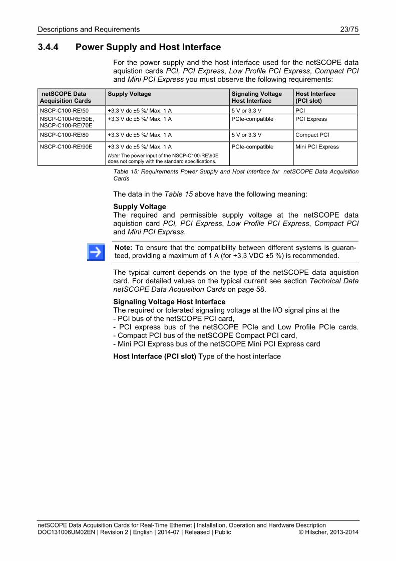
3.4.4 Power Supply and Host Interface
For the power supply and the host interface used for the netSCOPE data aquistion cards PCI, PCI Express, Low Profile PCI Express, Compact PCI and Mini PCI Express you must observe the following requirements:
netSCOPE Data Acquisition Cards
Supply Voltage Signaling Voltage Host Interface
Host Interface (PCI slot)
NSCP-C100-RE\50 +3,3 V dc ±5 %/ Max. 1 A 5 V or 3.3 V PCI
NSCP-C100-RE\50E, NSCP-C100-RE\70E
+3,3 V dc ±5 %/ Max. 1 A PCIe-compatible PCI Express
NSCP-C100-RE\80 +3.3 V dc ±5 %/ Max. 1 A 5 V or 3.3 V Compact PCI
NSCP-C100-RE\90E +3.3 V dc ±5 %/ Max. 1 A
Note: The power input of the NSCP-C100-RE\90E does not comply with the standard specifications.
PCIe-compatible Mini PCI Express
Table 15: Requirements Power Supply and Host Interface for netSCOPE Data Acquisition Cards
The data in the Table 15 above have the following meaning:
Supply Voltage The required and permissible supply voltage at the netSCOPE data aquistion card PCI, PCI Express, Low Profile PCI Express, Compact PCI and Mini PCI Express.
Note: To ensure that the compatibility between different systems is guaran-teed, providing a maximum of 1 A (for +3,3 VDC ±5 %) is recommended.
The typical current depends on the type of the netSCOPE data aquistion card. For detailed values on the typical current see section Technical Data netSCOPE Data Acquisition Cards on page 58.
Signaling Voltage Host Interface The required or tolerated signaling voltage at the I/O signal pins at the - PCI bus of the netSCOPE PCI card, - PCI express bus of the netSCOPE PCIe and Low Profile PCIe cards. - Compact PCI bus of the netSCOPE Compact PCI card, - Mini PCI Express bus of the netSCOPE Mini PCI Express card
Host Interface (PCI slot) Type of the host interface
Descriptions and Requirements 24/75
netSCOPE Data Acquisition Cards for Real-Time Ethernet | Installation, Operation and Hardware Description DOC131006UM02EN | Revision 2 | English | 2014-07 | Released | Public © Hilscher, 2013-2014
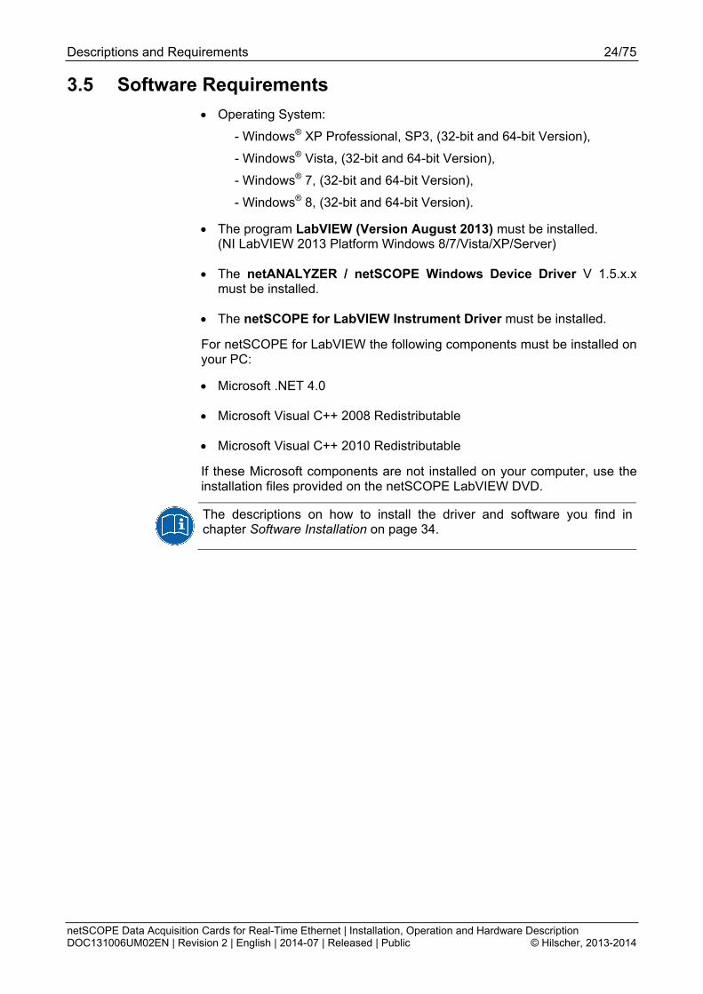
3.5 Software Requirements
Operating System:
- Windows® XP Professional, SP3, (32-bit and 64-bit Version),
- Windows® Vista, (32-bit and 64-bit Version),
- Windows® 7, (32-bit and 64-bit Version),
- Windows® 8, (32-bit and 64-bit Version).
The program LabVIEW (Version August 2013) must be installed. (NI LabVIEW 2013 Platform Windows 8/7/Vista/XP/Server)
The netANALYZER / netSCOPE Windows Device Driver V 1.5.x.x must be installed.
The netSCOPE for LabVIEW Instrument Driver must be installed.
For netSCOPE for LabVIEW the following components must be installed on your PC:
Microsoft .NET 4.0
Microsoft Visual C++ 2008 Redistributable
Microsoft Visual C++ 2010 Redistributable
If these Microsoft components are not installed on your computer, use the installation files provided on the netSCOPE LabVIEW DVD.
The descriptions on how to install the driver and software you find in chapter Software Installation on page 34.
Getting Started 25/75
netSCOPE Data Acquisition Cards for Real-Time Ethernet | Installation, Operation and Hardware Description DOC131006UM02EN | Revision 2 | English | 2014-07 | Released | Public © Hilscher, 2013-2014
4 Getting Started
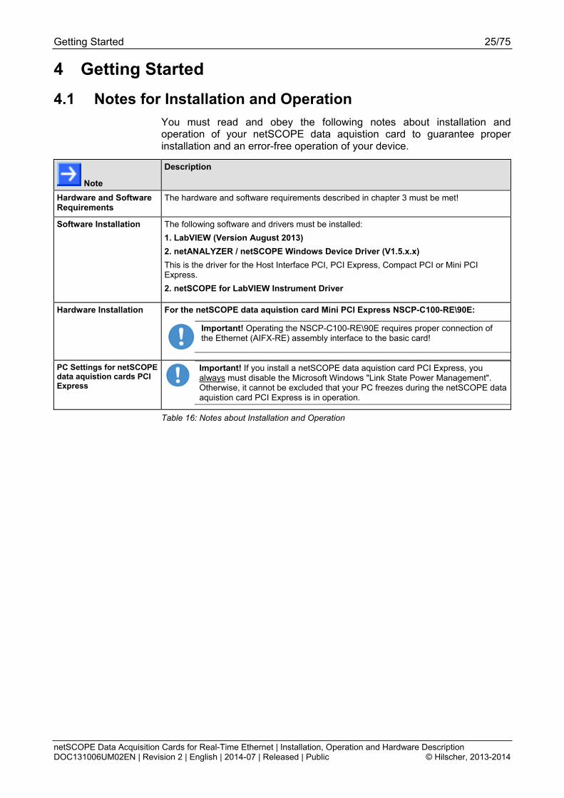
4.1 Notes for Installation and Operation
You must read and obey the following notes about installation and operation of your netSCOPE data aquistion card to guarantee proper installation and an error-free operation of your device.
Note
Description
Hardware and Software Requirements
The hardware and software requirements described in chapter 3 must be met!
Software Installation The following software and drivers must be installed:
1. LabVIEW (Version August 2013)
2. netANALYZER / netSCOPE Windows Device Driver (V1.5.x.x)
This is the driver for the Host Interface PCI, PCI Express, Compact PCI or Mini PCI Express.
2. netSCOPE for LabVIEW Instrument Driver
Hardware Installation For the netSCOPE data aquistion card Mini PCI Express NSCP-C100-RE\90E:
Important! Operating the NSCP-C100-RE\90E requires proper connection of the Ethernet (AIFX-RE) assembly interface to the basic card!
PC Settings for netSCOPE data aquistion cards PCI Express
Important! If you install a netSCOPE data aquistion card PCI Express, you always must disable the Microsoft Windows "Link State Power Management". Otherwise, it cannot be excluded that your PC freezes during the netSCOPE data aquistion card PCI Express is in operation.
Table 16: Notes about Installation and Operation

Getting Started 26/75
netSCOPE Data Acquisition Cards for Real-Time Ethernet | Installation, Operation and Hardware Description DOC131006UM02EN | Revision 2 | English | 2014-07 | Released | Public © Hilscher, 2013-2014
4.2 Installation and Configuration netSCOPE Data Acquisition Card
The following table describes the steps for the software and hardware installation and for the configuration of a netSCOPE data aquistion card Real-Time Ethernet.
# Step Description For detailed information see manual / section
Page
1 Installing Driver and Software
1.1 Install netANALYZER / netSCOPE Windows Device Driver
- Insert the netSCOPE LabVIEW DVD
- select Install Windows Device Driver
Open Instrument Driver Directory and follow to the instructions of the installation wizard to install the netANALYZER / netSCOPE Windows Device Driver.
Note: If the installation program does not start automatically start the *.msi or Setup.exe program of the netANALYZER / netSCOPE Windows Device Driver in the driver folder of the DVD.
Software Installation
1.2 Install netSCOPE for LabVIEW Instrument Driver
- Select Open Instrument Driver Directory. - Extract the instrument driver.zip file to an arbitrary location.
34
2 Preparing Hardware Installation
2.1 Take precautions on Electrostatically sensitive Devices
Electrostatically sensitive Devices Make sure, that the netSCOPE data aquistion card is grounded via the endplate and the PC and make sure, that you are discharged when you install/ uninstall the netSCOPE data aquistion card.
Electrostatically sensitive Devices
15
2.2 Glue sticker on the front plate.
For NSCP-C100-RE\50, NSCP-C100-RE\50E, NSCP-C100-RE\70E, NSCP-C100-RE\80
- Glue the sticker on the front plate of the netSCOPE data aquistion card.
Installing netSCOPE Data Acquisition Card
42
3 Hardware Installation Installing netSCOPE data aquistion card. Take required safety precautions.
3.1 Take safety precautions
Lethal Electrical Shock caused by parts with more than 50V! Disconnect the power plug of the PC or of the connecting device. Make sure, that the power supply is off at the PC or at the connecting device.
Electrical Shock Hazard 13
3.2 Open cabinet - Now open the cabinet of the PC or of the connecting device.
3.3 Installing netSCOPE data aquistion card
- Plug in and mount the netSCOPE data aquistion card.
Installing netSCOPE Data Acquisition Card
42
Getting Started 27/75
netSCOPE Data Acquisition Cards for Real-Time Ethernet | Installation, Operation and Hardware Description DOC131006UM02EN | Revision 2 | English | 2014-07 | Released | Public © Hilscher, 2013-2014
# Step Description For detailed information see manual / section
Page
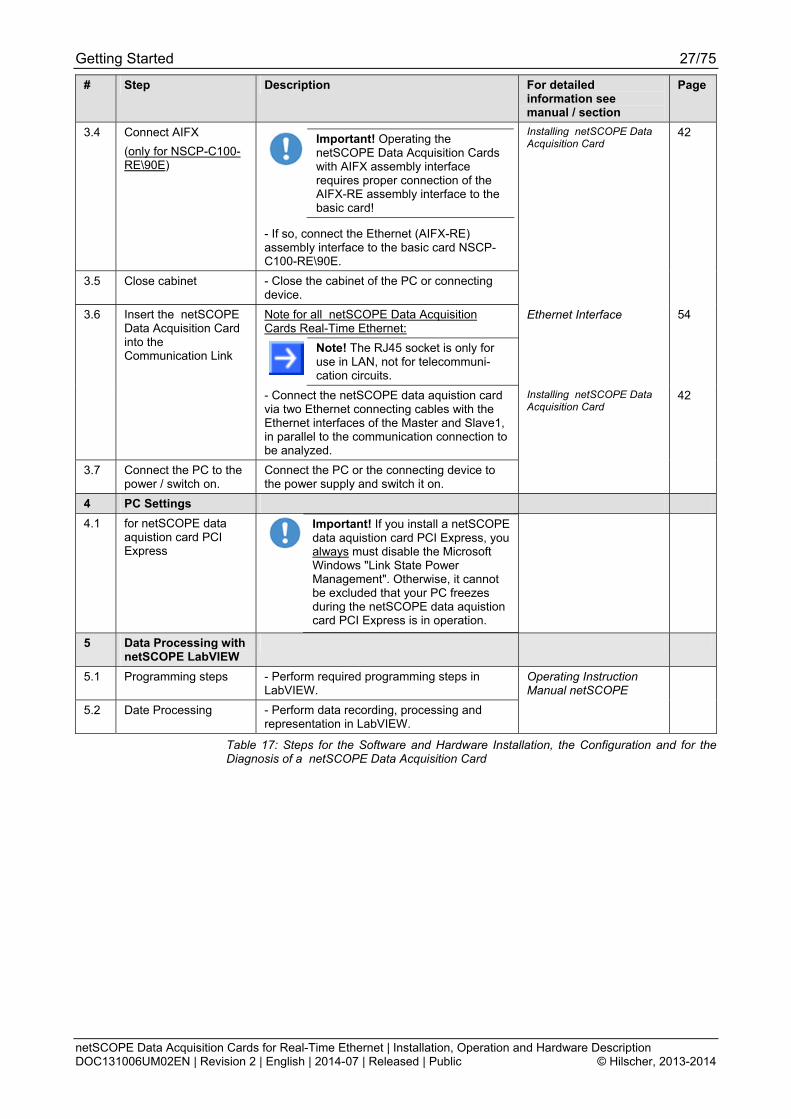
3.4 Connect AIFX
(only for NSCP-C100-RE\90E)
Important! Operating the netSCOPE Data Acquisition Cards with AIFX assembly interface requires proper connection of the AIFX-RE assembly interface to the basic card!
- If so, connect the Ethernet (AIFX-RE) assembly interface to the basic card NSCP-C100-RE\90E.
Installing netSCOPE Data Acquisition Card
42
3.5 Close cabinet - Close the cabinet of the PC or connecting device.
3.6 Insert the netSCOPE Data Acquisition Card into the Communication Link
Note for all netSCOPE Data Acquisition Cards Real-Time Ethernet:
Note! The RJ45 socket is only for use in LAN, not for telecommuni-cation circuits.
Ethernet Interface 54
- Connect the netSCOPE data aquistion card via two Ethernet connecting cables with the Ethernet interfaces of the Master and Slave1, in parallel to the communication connection to be analyzed.
Installing netSCOPE Data Acquisition Card
42
3.7 Connect the PC to the power / switch on.
Connect the PC or the connecting device to the power supply and switch it on.
4 PC Settings
4.1 for netSCOPE data aquistion card PCI Express
Important! If you install a netSCOPE data aquistion card PCI Express, you always must disable the Microsoft Windows "Link State Power Management". Otherwise, it cannot be excluded that your PC freezes during the netSCOPE data aquistion card PCI Express is in operation.
5 Data Processing with netSCOPE LabVIEW
5.1 Programming steps - Perform required programming steps in LabVIEW.
Operating Instruction Manual netSCOPE
5.2 Date Processing - Perform data recording, processing and representation in LabVIEW.
Table 17: Steps for the Software and Hardware Installation, the Configuration and for the Diagnosis of a netSCOPE Data Acquisition Card

Device Drawings 28/75
netSCOPE Data Acquisition Cards for Real-Time Ethernet | Installation, Operation and Hardware Description DOC131006UM02EN | Revision 2 | English | 2014-07 | Released | Public © Hilscher, 2013-2014
5 Device Drawings
5.1 netSCOPE Data Acquisition Cards PCI (NSCP-C100-RE\50) and PCI Express (NSCP-C100-RE\50E)
SYS
STA0
System LED (gelb/grün) / (yellow/green)Status-LED 0 und 1 (rot/grün) / Status LED 0 and 1 (red/green)
Pin
1:
TX
+
Pin
2: T
X-
Pin
3:
RX
+
Pin
4:
Te
rm 1
Pin
5: T
erm
1
Pin
6:
RX
-
Pin
7: T
erm
2
Pin
8:
Te
rm 2
LEDgrün / green
LEDgelb / yellow
Kanal 0 / Channel 0 (CH 0)
Kanal 1 / Channel 1 (CH 1)
STA1
X2
PCI Bus (X2/(X1), 124-polig / 124 pin)
Ethernet RJ45-Buchse / Ethernet RJ45 Socket
Figure 2: NSCP-C100-RE\50*
Pin
1: T
X+
Pin
2: T
X-
Pin
3: R
X+
Pin
4: T
erm
1
Pin
5:
Ter
m 1
Pin
6: R
X-
Pin
7:
Te
rm 2
Pin
8:
Ter
m 2
LEDgrün / green
LED gelb / yellow
Kanal 0 / Channel 0 (CH 0)
Kanal 1 / Channel 1 (CH 1)
PCI Express Bus (36-polig / 36 pin)
SYS
STA0
STA1
Ethernet RJ45-Buchse / Ethernet RJ45 Socket
System LED (gelb/grün) / (yellow/green)Status-LED 0 und 1 (rot/grün) / Status LED 0 and 1 (red/green)
Figure 3: NSCP-C100-RE\50E*
Note: *Device supports Auto Crossover Function. Only 100 Mbit/s connections 100BASE-T are supported.
Device Drawings 29/75
netSCOPE Data Acquisition Cards for Real-Time Ethernet | Installation, Operation and Hardware Description DOC131006UM02EN | Revision 2 | English | 2014-07 | Released | Public © Hilscher, 2013-2014
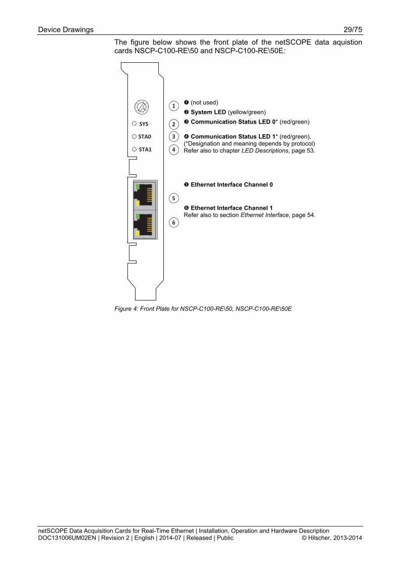
The figure below shows the front plate of the netSCOPE data aquistion cards NSCP-C100-RE\50 and NSCP-C100-RE\50E:
(not used)
System LED (yellow/green)
Communication Status LED 0* (red/green)
Communication Status LED 1* (red/green), (*Designation and meaning depends by protocol) Refer also to chapter LED Descriptions, page 53.
Ethernet Interface Channel 0
1
2
3
4
5
6
SYS
STA0
0
23
45
6
7 8
91
STA1
Ethernet Interface Channel 1 Refer also to section Ethernet Interface, page 54.
Figure 4: Front Plate for NSCP-C100-RE\50, NSCP-C100-RE\50E

Device Drawings 30/75
netSCOPE Data Acquisition Cards for Real-Time Ethernet | Installation, Operation and Hardware Description DOC131006UM02EN | Revision 2 | English | 2014-07 | Released | Public © Hilscher, 2013-2014
5.2 netSCOPE Data Acquisition Cards Low Profile PCI Express (NSCP-C100-RE\70E)
Pin
1: T
X+
Pin
2: T
X-
Pin
3: R
X+
Pin
4: T
erm
1
Pin
5: T
erm
1
Pin
6: R
X-
Pin
7: T
erm
2
Pin
8: T
erm
2
LED grün / green
LED gelb / yellow
Kanal 0 / Channel 0 (CH 0)
Kanal 1 / Channel 1 (CH 1)
Ethernet RJ45-Buchse / Ethernet RJ45 Socket
Status-LED 1 und 0 (rot/grün) / Status LED 1 and 0 (red/green)System-LED (gelb/grün) / System LED (yellow/green)
ST
A 1
ST
A 0
S
YS
PCI-Express-Bus / PCI Express Bus(X2/(X1), 64-polig / 64 pin)
Figure 5: NSCP-C100-RE\70E* (Hardware revision 1)
Note: *Device supports Auto Crossover Function. Only 100 Mbit/s connections 100BASE-T are supported.
The figure below shows the front plate of the netSCOPE data aquistion card NSCP-C100-RE\70E:
(not used)
Communication Status LEDs COM1*
Communication Status LEDs COM0*
System LED (yellow/green)
(*red/green, Designation and meaning depends by protocol). Refer also to chapter LED Descriptions, page 53.
Ethernet Interface Channel 0
ST
A1
ST
A0
SY
S
4
5
6
3
2
1
Ethernet Interface Channel 1 Refer also to section Ethernet Interface, page 54.
Figure 6: Front Plate for NSCP-C100-RE\70E
Device Drawings 31/75
netSCOPE Data Acquisition Cards for Real-Time Ethernet | Installation, Operation and Hardware Description DOC131006UM02EN | Revision 2 | English | 2014-07 | Released | Public © Hilscher, 2013-2014
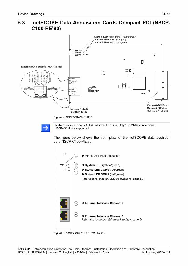
5.3 netSCOPE Data Acquisition Cards Compact PCI (NSCP-C100-RE\80)
Pin
1: T
X+
Pin
2: T
X-
Pin
3: R
X+
Pin
4: T
erm
1
Pin
5: T
erm
1
Pin
6: R
X-
Pin
7: T
erm
2
Pin
8: T
erm
2
Kanal 0 / Channel 0 (CH 0)
Kanal 1 / Channel 1 (CH 1)
Ethernet RJ45-Buchse / RJ45 Socket
Kompakt-PCI-Bus / Compact PCI Bus(135-polig / 135 pin)
Auswurfhebel / Ejection Lever
System LED (gelb/grün) / (yellow/green)Status-LED 0 und 1 (rot/grün) / Status LED 0 and 1 (red/green)
LEDgrün / green
LED gelb / yellow
SYSSTA 0STA 1
Figure 7: NSCP-C100-RE\80*
Note: *Device supports Auto Crossover Function. Only 100 Mbit/s connections 100BASE-T are supported.
The figure below shows the front plate of the netSCOPE data aquistion card NSCP-C100-RE\80:
Mini B USB Plug (not used)
System LED (yellow/green)
Status LED COM0 (red/green)
Status LED COM1 (red/green)
Refer also to chapter, LED Descriptions, page 53.
Ethernet Interface Channel 0
1
2
3
4
5
6
SYS
STA0
STA1
Ethernet Interface Channel 1 Refer also to section Ethernet Interface, page 54.
Figure 8: Front Plate NSCP-C100-RE\80

Device Drawings 32/75
netSCOPE Data Acquisition Cards for Real-Time Ethernet | Installation, Operation and Hardware Description DOC131006UM02EN | Revision 2 | English | 2014-07 | Released | Public © Hilscher, 2013-2014
5.4 netSCOPE Data Acquisition Cards Mini PCI Express
5.4.1 NSCP-C100-RE\90E
System LED (gelb/grün) / (yellow/green)
Kabelstecker Ethernet / Cable Connector Ethernet
(X4, 20-polig / 20 pin)
Mini PCI Express Bus (X1/(X2), 52-polig
Figure 9: Basic Card for NSCP-C100-RE\90E*
Note: *Device supports Auto Crossover Function. Only 100 Mbit/s connections 100BASE-T are supported.
For the pin assignment of the Mini PCI Express bus to section Pin Assignment for Mini PCI Express Bus on page 57.
For information on the card height refer to section the Card Height and Panel Cutout NSCP-C100-RE\90E
Notes on the Card Height on page 22.
Device Drawings 33/75
netSCOPE Data Acquisition Cards for Real-Time Ethernet | Installation, Operation and Hardware Description DOC131006UM02EN | Revision 2 | English | 2014-07 | Released | Public © Hilscher, 2013-2014
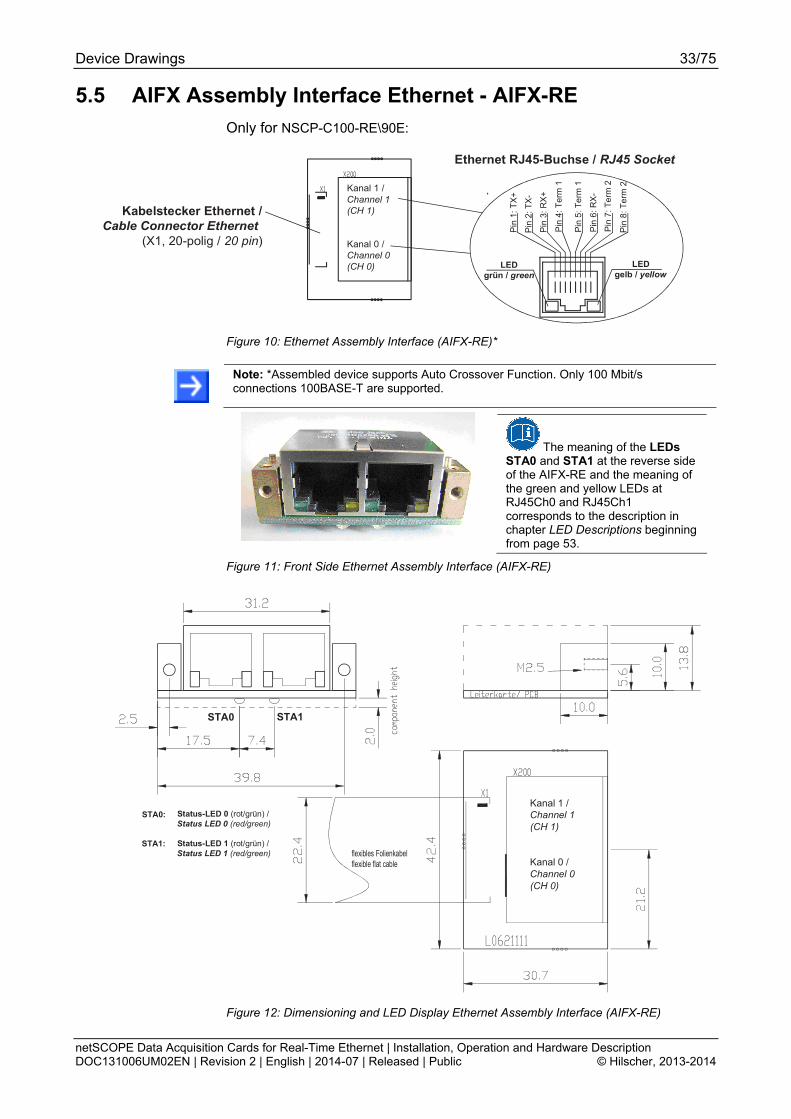
5.5 AIFX Assembly Interface Ethernet - AIFX-RE
Only for NSCP-C100-RE\90E:
Kanal 1 / Channel 1 (CH 1)
Kanal 0 / Channel 0 (CH 0)
Pin
1: T
X+
Pin
2: T
X-
Pin
3:
RX
+
Pin
4:
Ter
m 1
Pin
5:
Ter
m 1
Pin
6:
RX
-
Pin
7:
Ter
m 2
Pin
8: T
erm
2
LED grün / green
LED gelb / yellow
Ethernet RJ45-Buchse / RJ45 Socket
Kabelstecker Ethernet / Cable Connector Ethernet
(X1, 20-polig / 20 pin)
Figure 10: Ethernet Assembly Interface (AIFX-RE)*
Note: *Assembled device supports Auto Crossover Function. Only 100 Mbit/s connections 100BASE-T are supported.
The meaning of the LEDs STA0 and STA1 at the reverse side of the AIFX-RE and the meaning of the green and yellow LEDs at RJ45Ch0 and RJ45Ch1 corresponds to the description in chapter LED Descriptions beginning from page 53.
Figure 11: Front Side Ethernet Assembly Interface (AIFX-RE)
flexibles Folienkabelflexible flat cable
STA0 STA1
Kanal 1 / Channel 1 (CH 1)
Kanal 0 / Channel 0 (CH 0)
Status-LED 0 (rot/grün) / Status LED 0 (red/green)
Status-LED 1 (rot/grün) / Status LED 1 (red/green)
STA0:
STA1:
Figure 12: Dimensioning and LED Display Ethernet Assembly Interface (AIFX-RE)
Software Installation 34/75
netSCOPE Data Acquisition Cards for Real-Time Ethernet | Installation, Operation and Hardware Description DOC131006UM02EN | Revision 2 | English | 2014-07 | Released | Public © Hilscher, 2013-2014
6 Software Installation
6.1 netSCOPE LabVIEW DVD Autostart Menu
For the software installation for your netSCOPE data aquistion card the netSCOPE LabVIEW DVD provides the netANALYZER / netSCOPE Windows Device Driver, the netSCOPE Software and the documentations.
In the netSCOPE LabVIEW DVD autostart menu you can select:
Install Windows Device Driver
Via this option you can install the netANALYZER / netSCOPE Windows Device Driver
Open Instrument Driver Directory
Via this option you can install the netSCOPE for LabVIEW Instrument Driver
Open Documentation Directory
Via this option you can access to the documentations (netSCOPE User and Operating Instruction Manual)
6.2 netANALYZER / netSCOPE Windows Device Driver
To install the netANALYZER / netSCOPE Windows Device Driver proceed as described hereafter:
1. Close all programs!
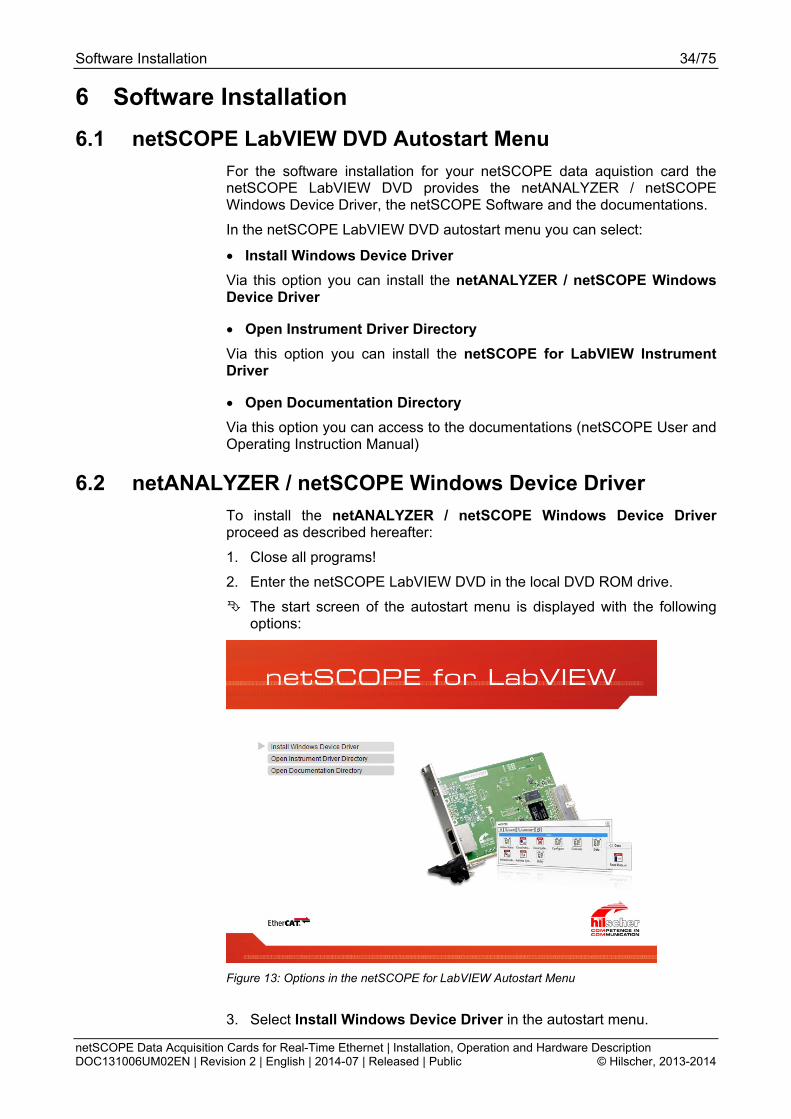
2. Enter the netSCOPE LabVIEW DVD in the local DVD ROM drive.
The start screen of the autostart menu is displayed with the following options:
Figure 13: Options in the netSCOPE for LabVIEW Autostart Menu
3. Select Install Windows Device Driver in the autostart menu.

Software Installation 35/75
netSCOPE Data Acquisition Cards for Real-Time Ethernet | Installation, Operation and Hardware Description DOC131006UM02EN | Revision 2 | English | 2014-07 | Released | Public © Hilscher, 2013-2014
Note: Under Windows® you need administration rights for the installation!
The netANALYZER / netSCOPE Windows Device Driver Setup Wizard netANALYZER Device Driver appears.
Figure 14: netANALYZER / netSCOPE Windows Device Driver Setup Wizard
4. Click on Install.
The installation is started.
Figure 15: netANALYZER / netSCOPE Windows Device Driver Setup Wizard

Software Installation 36/75
netSCOPE Data Acquisition Cards for Real-Time Ethernet | Installation, Operation and Hardware Description DOC131006UM02EN | Revision 2 | English | 2014-07 | Released | Public © Hilscher, 2013-2014
The screen Completed is displayed.
Figure 16: netANALYZER / netSCOPE Windows Device Driver Setup Wizard
Click Finish.
The netANALYZER / netSCOPE Windows Device Driver installation is complete.
Software Installation 37/75
netSCOPE Data Acquisition Cards for Real-Time Ethernet | Installation, Operation and Hardware Description DOC131006UM02EN | Revision 2 | English | 2014-07 | Released | Public © Hilscher, 2013-2014
6.3 netSCOPE for LabVIEW Instrument Driver
To install the netSCOPE for LabVIEW Instrument Driver proceed as described hereafter:
1. Close all programs!
2. Enter the netSCOPE LabVIEW DVD in the local DVD ROM drive.
The start screen of the autostart menu is displayed with the following options:
Figure 17: Options in the netSCOPE for LabVIEW Autostart Menu
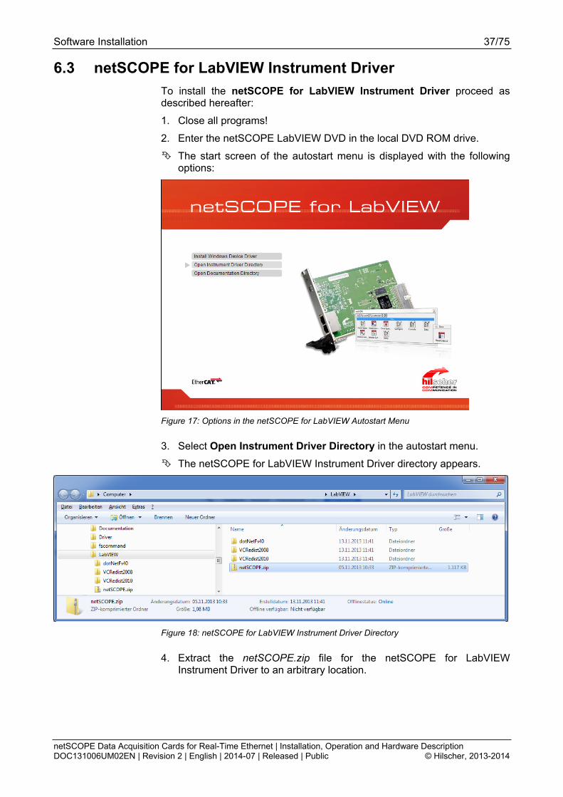
3. Select Open Instrument Driver Directory in the autostart menu.
The netSCOPE for LabVIEW Instrument Driver directory appears.
Figure 18: netSCOPE for LabVIEW Instrument Driver Directory
4. Extract the netSCOPE.zip file for the netSCOPE for LabVIEW Instrument Driver to an arbitrary location.
Software Installation 38/75
netSCOPE Data Acquisition Cards for Real-Time Ethernet | Installation, Operation and Hardware Description DOC131006UM02EN | Revision 2 | English | 2014-07 | Released | Public © Hilscher, 2013-2014
6.4 Microsoft Software Components
If the Microsoft components
Microsoft .NET 4.0
Microsoft Visual C++ 2008 Redistributable
Microsoft Visual C++ 2010 Redistributable
are not installed on your computer, install them from the netSCOPE LabVIEW DVD. Therefore:
1. Close all programs!
2. Enter the netSCOPE LabVIEW DVD in the local DVD ROM drive.
The start screen of the autostart menu is displayed with the following options:
Figure 19: Options in the netSCOPE for LabVIEW Autostart Menu
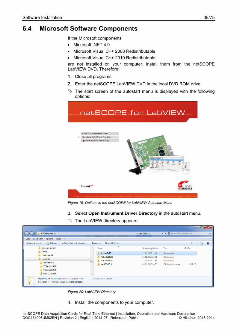
3. Select Open Instrument Driver Directory in the autostart menu.
The LabVIEW directory appears.
Figure 20: LabVIEW Directory
4. Install the components to your computer.
Software Installation 39/75
netSCOPE Data Acquisition Cards for Real-Time Ethernet | Installation, Operation and Hardware Description DOC131006UM02EN | Revision 2 | English | 2014-07 | Released | Public © Hilscher, 2013-2014
6.5 Documentation
To open the Documentation directory
1. Enter the netSCOPE LabVIEW DVD in the local DVD ROM drive.
The start screen of the autostart menu is displayed with the following options:
Figure 21: Options in the netSCOPE for LabVIEW Autostart Menu
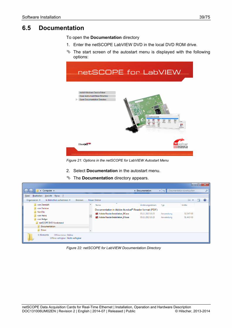
2. Select Documentation in the autostart menu.
The Documentation directory appears.
Figure 22: netSCOPE for LabVIEW Documentation Directory

Hardware Installation and Uninstalling 40/75
netSCOPE Data Acquisition Cards for Real-Time Ethernet | Installation, Operation and Hardware Description DOC131006UM02EN | Revision 2 | English | 2014-07 | Released | Public © Hilscher, 2013-2014
7 Hardware Installation and Uninstalling To install / uninstall the netSCOPE data aquistion cards for Real-Time Ethernet:
PCI (NSCP-C100-RE\50)
PCI Express (NSCP-C100-RE\50E)
Low Profile PCIe (NSCP-C100-RE\70E)
Compact PCI (NSCP-C100-RE\80)
Mini PCI Express (NSCP-C100-RE\90E)
handle as described in the sections hereafter. The device drawing of your netSCOPE data aquistion card gives information on the manual control elements of your device.
This user manual provides descriptions of the installation of the software and the installation, operation and hardware of the netSCOPE data aquistion cards PCI, PCI Express, Low Profile PCI Express, Compact PCI and Mini PCI Express under Windows® XP, Windows® Vista, Windows® 7 and Windows® 8, as listed subsequently.
For the installation, uninstalling and replacement of the netSCOPE data aquistion card check any notes in the overview in chapter Getting Started on page 25.
7.1 Safety Messages on Personal Injury
Obey to the following safety messages on personal injury, when installing, uninstalling or replacing the netSCOPE data aquistion card.
7.1.1 Electrical Shock Hazard
Lethal Electrical Shock caused by parts with more than 50V!
HAZARDOUS VOLTAGE inside of the PC or of the connecting device.
Strictly obey to all safety rules provided by the device’s manufacturer in the documentation!
First disconnect the power plug of the PC or of the connecting device, before you open the cabinet.
Make sure, that the power supply is off at the PC or at the connecting device.
Open the PC cabinet and install or remove the netSCOPE data aquistion card only after disconnecting power.

Hardware Installation and Uninstalling 41/75
netSCOPE Data Acquisition Cards for Real-Time Ethernet | Installation, Operation and Hardware Description DOC131006UM02EN | Revision 2 | English | 2014-07 | Released | Public © Hilscher, 2013-2014
7.2 Property Damage Messages
Obey to the following property damage messages, when installing, uninstalling or replacing the netSCOPE data aquistion card.
7.2.1 Device Destruction by exceeding allowed Supply Voltage
Adhere for all netSCOPE data aquistion cards described in this manual the instruction hereafter:
Device Destruction!
Use only the permissible supply voltage to operate the netSCOPE data aquistion card.
Operating the netSCOPE data aquistion card with a supply voltage above of the specified range leads to device destruction.
7.2.2 Device Destruction by exceeding allowed Signaling Voltage
Adhere for all netSCOPE data aquistion cards described in this manual the instruction hereafter:
Device Destruction!
All I/O signal pins at the netSCOPE data aquistion card tolerate only the specified signaling voltage!
Operation the netSCOPE data aquistion card with a signaling voltage other than the specified signaling voltage may lead to severe damage to the netSCOPE data aquistion card!
For detailed information on the supply and signaling voltage of the netSCOPE data aquistion cards described in this manual, refer to section Power Supply and Host Interface on page 23.
7.2.3 Electrostatically sensitive Devices
Adhere to the necessary safety precautions for components that are vulnerable with electrostatic discharge.
Electrostatically sensitive Devices
To prevent damage to the PC and the netSCOPE data aquistion card, make sure, that the netSCOPE data aquistion card is grounded via the endplate and the PC and make sure, that you are discharged when you install/uninstall the netSCOPE data aquistion card.
Hardware Installation and Uninstalling 42/75
netSCOPE Data Acquisition Cards for Real-Time Ethernet | Installation, Operation and Hardware Description DOC131006UM02EN | Revision 2 | English | 2014-07 | Released | Public © Hilscher, 2013-2014
7.3 Installing netSCOPE Data Acquisition Card
Electrostatically sensitive Devices
3. Adhere to the necessary safety precautions for components that are vulnerable with electrostatic discharge.
Electrostatically sensitive Devices
To prevent damage to the PC and the netSCOPE card, make sure, thatthe netSCOPE card is grounded via the endplate and the PC and makesure, that you are discharged when you install/uninstall the netSCOPEcard.
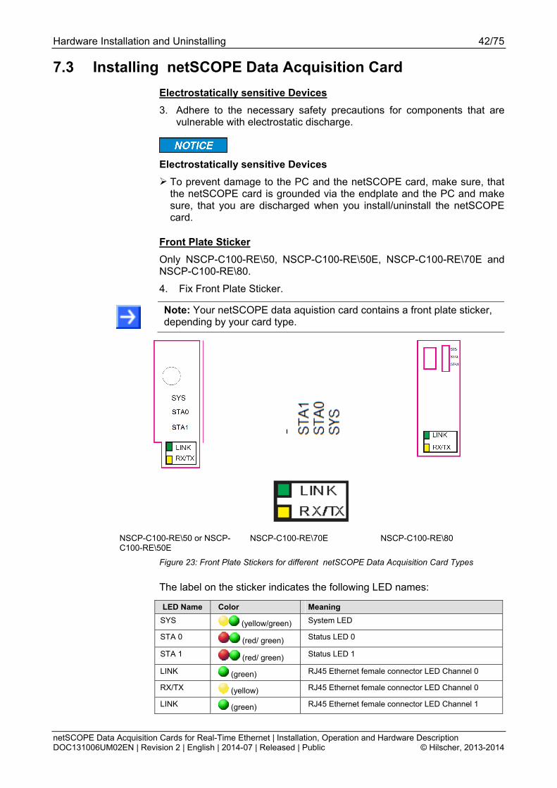
Front Plate Sticker
Only NSCP-C100-RE\50, NSCP-C100-RE\50E, NSCP-C100-RE\70E and NSCP-C100-RE\80.
4. Fix Front Plate Sticker.
Note: Your netSCOPE data aquistion card contains a front plate sticker, depending by your card type.
NSCP-C100-RE\50 or NSCP-C100-RE\50E
NSCP-C100-RE\70E NSCP-C100-RE\80
Figure 23: Front Plate Stickers for different netSCOPE Data Acquisition Card Types
The label on the sticker indicates the following LED names:
LED Name Color Meaning
SYS (yellow/green) System LED
STA 0 (red/ green) Status LED 0
STA 1 (red/ green) Status LED 1
LINK (green) RJ45 Ethernet female connector LED Channel 0
RX/TX (yellow) RJ45 Ethernet female connector LED Channel 0
LINK (green) RJ45 Ethernet female connector LED Channel 1
Hardware Installation and Uninstalling 43/75
netSCOPE Data Acquisition Cards for Real-Time Ethernet | Installation, Operation and Hardware Description DOC131006UM02EN | Revision 2 | English | 2014-07 | Released | Public © Hilscher, 2013-2014
RX/TX (yellow) RJ45 Ethernet female connector LED Channel 1
Table 18: LED Labeling
For further information refer to chapter LED Descriptions page 53.
Hardware Installation and Uninstalling 44/75
netSCOPE Data Acquisition Cards for Real-Time Ethernet | Installation, Operation and Hardware Description DOC131006UM02EN | Revision 2 | English | 2014-07 | Released | Public © Hilscher, 2013-2014
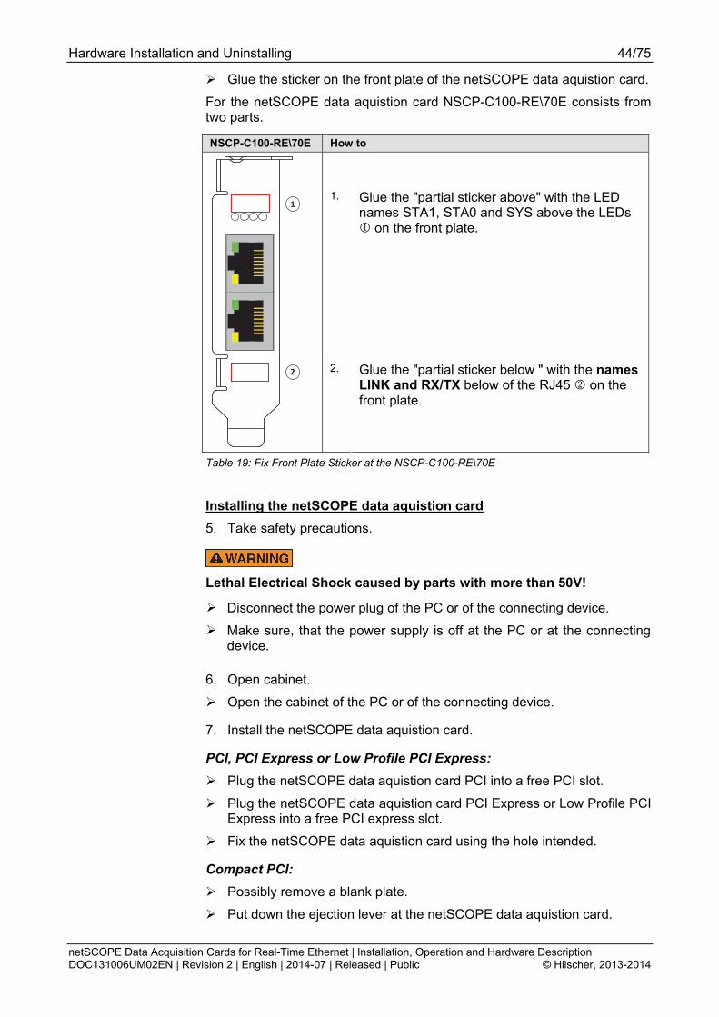
Glue the sticker on the front plate of the netSCOPE data aquistion card.
For the netSCOPE data aquistion card NSCP-C100-RE\70E consists from two parts.
NSCP-C100-RE\70E How to
1.
Glue the "partial sticker above" with the LED names STA1, STA0 and SYS above the LEDs on the front plate.
1
2
2. Glue the "partial sticker below " with the names LINK and RX/TX below of the RJ45 on the front plate.
Table 19: Fix Front Plate Sticker at the NSCP-C100-RE\70E
Installing the netSCOPE data aquistion card
5. Take safety precautions.
Lethal Electrical Shock caused by parts with more than 50V!
Disconnect the power plug of the PC or of the connecting device.
Make sure, that the power supply is off at the PC or at the connecting device.
6. Open cabinet.
Open the cabinet of the PC or of the connecting device.
7. Install the netSCOPE data aquistion card.
PCI, PCI Express or Low Profile PCI Express: Plug the netSCOPE data aquistion card PCI into a free PCI slot.
Plug the netSCOPE data aquistion card PCI Express or Low Profile PCI Express into a free PCI express slot.
Fix the netSCOPE data aquistion card using the hole intended.
Compact PCI: Possibly remove a blank plate.
Put down the ejection lever at the netSCOPE data aquistion card.
Hardware Installation and Uninstalling 45/75
netSCOPE Data Acquisition Cards for Real-Time Ethernet | Installation, Operation and Hardware Description DOC131006UM02EN | Revision 2 | English | 2014-07 | Released | Public © Hilscher, 2013-2014
Plug the netSCOPE data aquistion card Compact PCI into a free Compact PCI slot.
Fasten the netSCOPE data aquistion card.
Tip up the lever and click in.
Screw the netSCOPE data aquistion card with two screws on the wholes above and below.
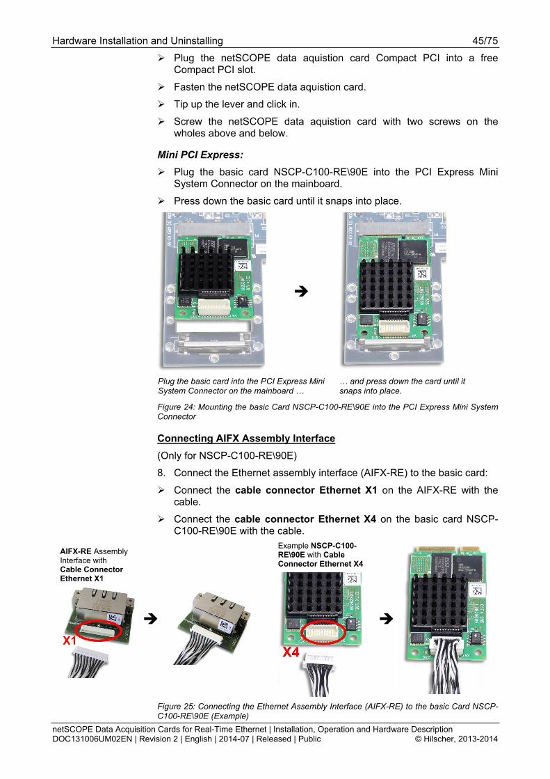
Mini PCI Express: Plug the basic card NSCP-C100-RE\90E into the PCI Express Mini
System Connector on the mainboard.
Press down the basic card until it snaps into place.
Plug the basic card into the PCI Express Mini System Connector on the mainboard …
… and press down the card until it snaps into place.
Figure 24: Mounting the basic Card NSCP-C100-RE\90E into the PCI Express Mini System Connector
Connecting AIFX Assembly Interface
(Only for NSCP-C100-RE\90E)
8. Connect the Ethernet assembly interface (AIFX-RE) to the basic card:
Connect the cable connector Ethernet X1 on the AIFX-RE with the cable.
Connect the cable connector Ethernet X4 on the basic card NSCP-C100-RE\90E with the cable.
AIFX-RE Assembly Interface with Cable Connector Ethernet X1
Example NSCP-C100-RE\90E with Cable Connector Ethernet X4
Figure 25: Connecting the Ethernet Assembly Interface (AIFX-RE) to the basic Card NSCP-C100-RE\90E (Example)
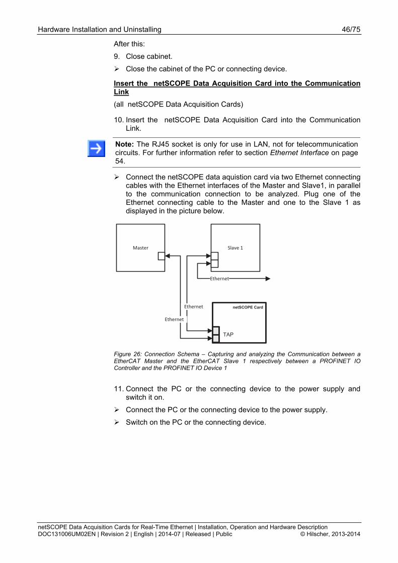
Hardware Installation and Uninstalling 46/75
netSCOPE Data Acquisition Cards for Real-Time Ethernet | Installation, Operation and Hardware Description DOC131006UM02EN | Revision 2 | English | 2014-07 | Released | Public © Hilscher, 2013-2014
After this:
9. Close cabinet.
Close the cabinet of the PC or connecting device.
Insert the netSCOPE Data Acquisition Card into the Communication Link
(all netSCOPE Data Acquisition Cards)
10. Insert the netSCOPE Data Acquisition Card into the Communication Link.
Note: The RJ45 socket is only for use in LAN, not for telecommunication circuits. For further information refer to section Ethernet Interface on page 54.
Connect the netSCOPE data aquistion card via two Ethernet connecting cables with the Ethernet interfaces of the Master and Slave1, in parallel to the communication connection to be analyzed. Plug one of the Ethernet connecting cable to the Master and one to the Slave 1 as displayed in the picture below.
Master Slave 1
netSCOPE Card
TAP
Ethernet
Ethernet
Ethernet
Figure 26: Connection Schema – Capturing and analyzing the Communication between a EtherCAT Master and the EtherCAT Slave 1 respectively between a PROFINET IO Controller and the PROFINET IO Device 1
11. Connect the PC or the connecting device to the power supply and switch it on.
Connect the PC or the connecting device to the power supply.
Switch on the PC or the connecting device.

Hardware Installation and Uninstalling 47/75
netSCOPE Data Acquisition Cards for Real-Time Ethernet | Installation, Operation and Hardware Description DOC131006UM02EN | Revision 2 | English | 2014-07 | Released | Public © Hilscher, 2013-2014
7.4 Uninstalling netSCOPE Data Acquisition Cards
1. Take safety precautions.
Lethal Electrical Shock caused by parts with more than 50V!
Disconnect the power plug of the PC or of the connecting device.
Make sure, that the power supply is off at the PC or at the connecting device.
Electrostatically sensitive Devices
To prevent damage to the PC and the netSCOPE card, make sure, thatthe netSCOPE card is grounded via the endplate and the PC and makesure, that you are discharged when you install/uninstall the netSCOPEcard.
2. Remove the Ethernet connecting cables.
Remove the Ethernet connecting cables between the netSCOPE data aquistion card and the Master or the Device.
3. Open cabinet.
Open the cabinet of the PC or of the connecting device.
4. Uninstall netSCOPE data aquistion card.
PCI, PCI Express or Low Profile PCI Express: Loosen the netSCOPE data aquistion card.
Remove the netSCOPE data aquistion card from the PCI slot or from the PCI express slot.
Compact PCI: Unscrew the netSCOPE data aquistion card.
First press the grey button at the ejection lever.
Then press the ejection lever downwards.
Remove the netSCOPE data aquistion card from the compact PCI slot.
Possibly reinsert a blank plate.
Mini PCI Express: 5. Uninstall the Ethernet (AIFX-RE) assembly interface. (Only NSCP-
C100-RE\90E)
Remove the AIFX-RE assembly interface from the PC housing panel.
Disconnect the cable from the basic card NSCP-C100-RE\90E, cable connector Ethernet X4.

Hardware Installation and Uninstalling 48/75
netSCOPE Data Acquisition Cards for Real-Time Ethernet | Installation, Operation and Hardware Description DOC131006UM02EN | Revision 2 | English | 2014-07 | Released | Public © Hilscher, 2013-2014
6. Remove the basic Card. (Only NSCP-C100-RE\90E)
Press down the fastening clips (on the upper edge of the basic card), until the card flips up.
Press down the fastening clips (red arrows) of the basic card …
… until the card flips up.
Figure 27: Demounting the basic Card NSCP-C100-RE\90E from the PCI Express Mini System Connector
Remove the basic card from the PCI Express Mini System Connector.
After this:
7. Close cabinet (All netSCOPE data aquistion cards)
Close the cabinet of the PC or connecting device.
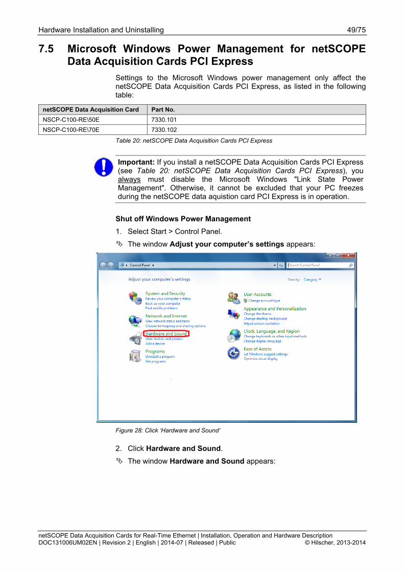
Hardware Installation and Uninstalling 49/75
netSCOPE Data Acquisition Cards for Real-Time Ethernet | Installation, Operation and Hardware Description DOC131006UM02EN | Revision 2 | English | 2014-07 | Released | Public © Hilscher, 2013-2014
7.5 Microsoft Windows Power Management for netSCOPE Data Acquisition Cards PCI Express
Settings to the Microsoft Windows power management only affect the netSCOPE Data Acquisition Cards PCI Express, as listed in the following table:
netSCOPE Data Acquisition Card Part No.
NSCP-C100-RE\50E 7330.101
NSCP-C100-RE\70E 7330.102
Table 20: netSCOPE Data Acquisition Cards PCI Express
Important: If you install a netSCOPE Data Acquisition Cards PCI Express (see Table 20: netSCOPE Data Acquisition Cards PCI Express), you always must disable the Microsoft Windows "Link State Power Management". Otherwise, it cannot be excluded that your PC freezes during the netSCOPE data aquistion card PCI Express is in operation.
Shut off Windows Power Management
1. Select Start > Control Panel.
The window Adjust your computer’s settings appears:
Figure 28: Click ‘Hardware and Sound’
2. Click Hardware and Sound.
The window Hardware and Sound appears:

Hardware Installation and Uninstalling 50/75
netSCOPE Data Acquisition Cards for Real-Time Ethernet | Installation, Operation and Hardware Description DOC131006UM02EN | Revision 2 | English | 2014-07 | Released | Public © Hilscher, 2013-2014
Figure 29: Click ‘Change when the computer sleeps’
3. Under Power Options click Change when the computer sleeps.
The window Change when the computer sleeps appears:
Figure 30: Click ‘Change advanced power settings’
4. Click Change advanced power settings.
The window Power Options > Advances settings:

Hardware Installation and Uninstalling 51/75
netSCOPE Data Acquisition Cards for Real-Time Ethernet | Installation, Operation and Hardware Description DOC131006UM02EN | Revision 2 | English | 2014-07 | Released | Public © Hilscher, 2013-2014
Figure 31: Click ‘Change settings that are currently unavailable’
5. Click Change settings that are currently unavailable.
6. Scroll down until PCI Express > Link State Power Management appears.
7. For Link State Power Management select the setting ‚Off’.
Figure 32: Set ‚Link State Power Management’ to ‘Off’
8. Apply the changed settings by OK.
Troubleshooting 52/75
netSCOPE Data Acquisition Cards for Real-Time Ethernet | Installation, Operation and Hardware Description DOC131006UM02EN | Revision 2 | English | 2014-07 | Released | Public © Hilscher, 2013-2014
8 Troubleshooting
8.1 Instructions for Problem Solving
In case of any error, follow the instructions for problem solving given here:
General
Check if the PC is on.
Check the netSCOPE data aquistion card operating requirements according to the requirements given in the section Notes for Installation and Operation on page 25.
LINK-LEDs
Check using the LINK LEDs status whether a connection to the Ethernet is established. Therefore use the descriptions on the LINK LEDs in the chapter LED Descriptions beginning from page 53.
Cable
Check that the pin assignment of the cable is correct. This means, the cable by which you connect the netSCOPE data aquistion card to the Master or Device.
Configuration
Check if the netSCOPE data aquistion card is configured properly.
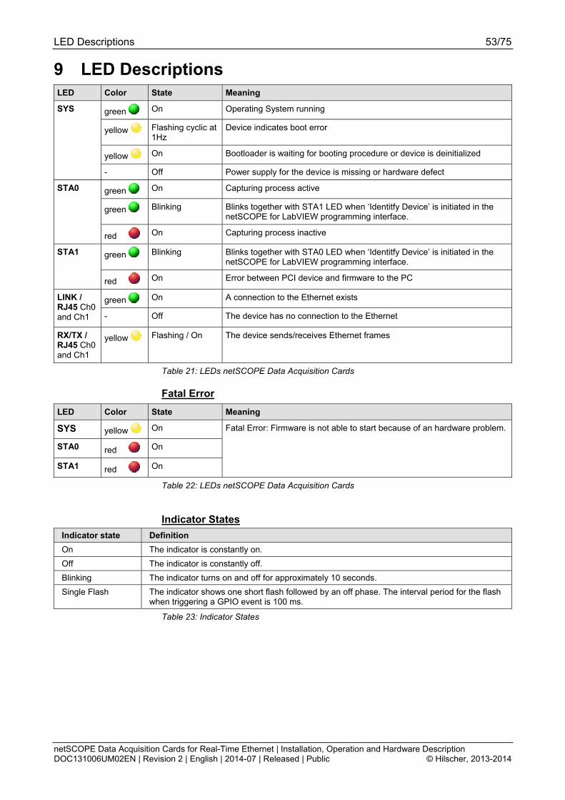
LED Descriptions 53/75
netSCOPE Data Acquisition Cards for Real-Time Ethernet | Installation, Operation and Hardware Description DOC131006UM02EN | Revision 2 | English | 2014-07 | Released | Public © Hilscher, 2013-2014
9 LED Descriptions LED Color State Meaning
green On Operating System running
yellow Flashing cyclic at 1Hz
Device indicates boot error
yellow On Bootloader is waiting for booting procedure or device is deinitialized
SYS
- Off Power supply for the device is missing or hardware defect
green On Capturing process active
green Blinking Blinks together with STA1 LED when ‘Identitfy Device’ is initiated in the netSCOPE for LabVIEW programming interface.
STA0
red On Capturing process inactive
green Blinking Blinks together with STA0 LED when ‘Identitfy Device’ is initiated in the netSCOPE for LabVIEW programming interface.
STA1
red On Error between PCI device and firmware to the PC
green On A connection to the Ethernet exists LINK / RJ45 Ch0 and Ch1 - Off The device has no connection to the Ethernet
RX/TX / RJ45 Ch0 and Ch1
yellow Flashing / On The device sends/receives Ethernet frames
Table 21: LEDs netSCOPE Data Acquisition Cards
Fatal Error
LED Color State Meaning
SYS yellow On
STA0 red On
STA1 red On
Fatal Error: Firmware is not able to start because of an hardware problem.
Table 22: LEDs netSCOPE Data Acquisition Cards
Indicator States
Indicator state Definition
On The indicator is constantly on.
Off The indicator is constantly off.
Blinking The indicator turns on and off for approximately 10 seconds.
Single Flash The indicator shows one short flash followed by an off phase. The interval period for the flash when triggering a GPIO event is 100 ms.
Table 23: Indicator States
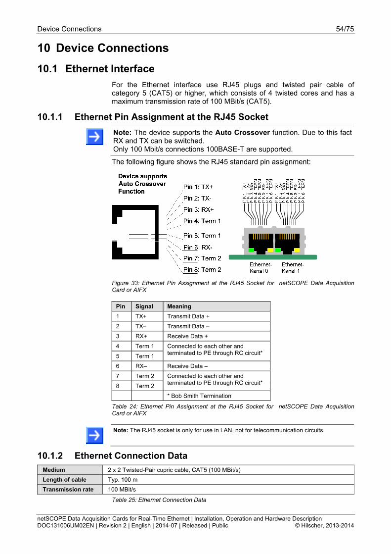
Device Connections 54/75
netSCOPE Data Acquisition Cards for Real-Time Ethernet | Installation, Operation and Hardware Description DOC131006UM02EN | Revision 2 | English | 2014-07 | Released | Public © Hilscher, 2013-2014
10 Device Connections
10.1 Ethernet Interface
For the Ethernet interface use RJ45 plugs and twisted pair cable of category 5 (CAT5) or higher, which consists of 4 twisted cores and has a maximum transmission rate of 100 MBit/s (CAT5).
10.1.1 Ethernet Pin Assignment at the RJ45 Socket
Note: The device supports the Auto Crossover function. Due to this fact RX and TX can be switched. Only 100 Mbit/s connections 100BASE-T are supported.
The following figure shows the RJ45 standard pin assignment:
Figure 33: Ethernet Pin Assignment at the RJ45 Socket for netSCOPE Data Acquisition Card or AIFX
Pin Signal Meaning
1 TX+ Transmit Data +
2 TX– Transmit Data –
3 RX+ Receive Data +
4 Term 1
5 Term 1
Connected to each other and terminated to PE through RC circuit*
6 RX– Receive Data –
7 Term 2
8 Term 2
Connected to each other and terminated to PE through RC circuit*
* Bob Smith Termination
Table 24: Ethernet Pin Assignment at the RJ45 Socket for netSCOPE Data Acquisition Card or AIFX
Note: The RJ45 socket is only for use in LAN, not for telecommunication circuits.
10.1.2 Ethernet Connection Data
Medium 2 x 2 Twisted-Pair cupric cable, CAT5 (100 MBit/s)
Length of cable Typ. 100 m
Transmission rate 100 MBit/s
Table 25: Ethernet Connection Data
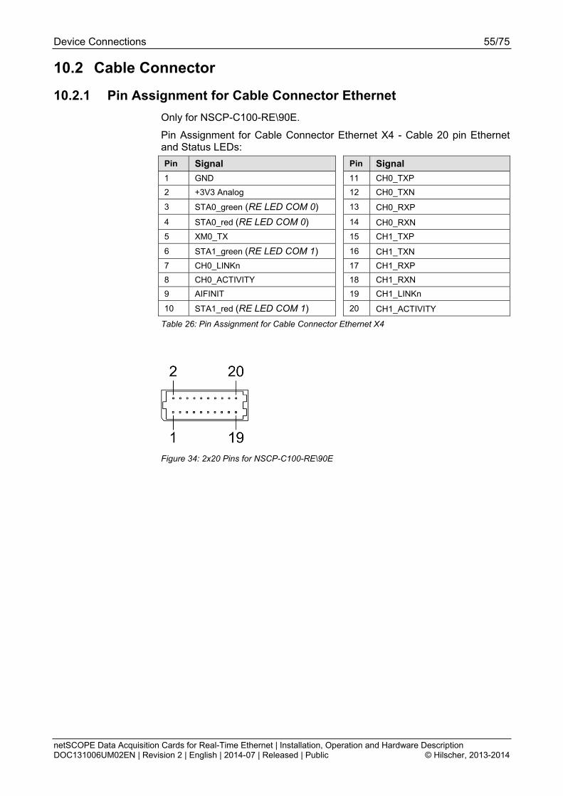
Device Connections 55/75
netSCOPE Data Acquisition Cards for Real-Time Ethernet | Installation, Operation and Hardware Description DOC131006UM02EN | Revision 2 | English | 2014-07 | Released | Public © Hilscher, 2013-2014
10.2 Cable Connector
10.2.1 Pin Assignment for Cable Connector Ethernet
Only for NSCP-C100-RE\90E.
Pin Assignment for Cable Connector Ethernet X4 - Cable 20 pin Ethernet and Status LEDs:
Pin Signal Pin Signal
1 GND 11 CH0_TXP
2 +3V3 Analog 12 CH0_TXN
3 STA0_green (RE LED COM 0) 13 CH0_RXP
4 STA0_red (RE LED COM 0) 14 CH0_RXN
5 XM0_TX 15 CH1_TXP
6 STA1_green (RE LED COM 1) 16 CH1_TXN
7 CH0_LINKn 17 CH1_RXP
8 CH0_ACTIVITY 18 CH1_RXN
9 AIFINIT 19 CH1_LINKn
10 STA1_red (RE LED COM 1) 20 CH1_ACTIVITY
Table 26: Pin Assignment for Cable Connector Ethernet X4
Figure 34: 2x20 Pins for NSCP-C100-RE\90E
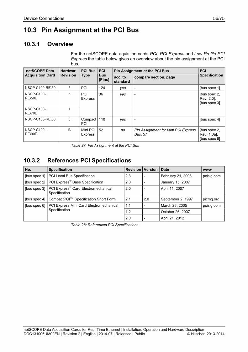
Device Connections 56/75
netSCOPE Data Acquisition Cards for Real-Time Ethernet | Installation, Operation and Hardware Description DOC131006UM02EN | Revision 2 | English | 2014-07 | Released | Public © Hilscher, 2013-2014
10.3 Pin Assignment at the PCI Bus
10.3.1 Overview
For the netSCOPE data aquistion cards PCI, PCI Express and Low Profile PCI Express the table below gives an overview about the pin assignment at the PCI bus.
Pin Assignment at the PCI Bus netSCOPE Data Acquisition Card
Hardwar Revision
PCI Bus Type
PCI Bus [Pins]
acc. to standard
compare section, page
PCI Specification
NSCP-C100-RE\50 5 PCI 124 yes - [bus spec 1]
NSCP-C100-RE\50E
5 PCI Express
36 yes - [bus spec 2, Rev. 2.0], [bus spec 3]
NSCP-C100-RE\70E
1
NSCP-C100-RE\80 3 Compact PCI
110 yes - [bus spec 4]
NSCP-C100-RE\90E
B Mini PCI Express
52 no Pin Assignment for Mini PCI Express Bus, 57
[bus spec 2, Rev. 1.0a], [bus spec 6]
Table 27: Pin Assignment at the PCI Bus
10.3.2 References PCI Specifications
No. Specification Revision Version Date www
[bus spec 1] PCI Local Bus Specification 2.3 - February 21, 2003 pcisig.com
[bus spec 2] PCI Express® Base Specification 2.0 - January 15, 2007
[bus spec 3] PCI Express® Card Electromechanical Specification
2.0 - April 11, 2007
[bus spec 4] CompactPCITM Specification Short Form 2.1 2.0 September 2, 1997 picmg.org
1.1 - March 28, 2005 pcisig.com
1.2 - October 26, 2007
[bus spec 6] PCI Express Mini Card Electromechanical Specification
2.0 - April 21, 2012
Table 28: References PCI Specifications
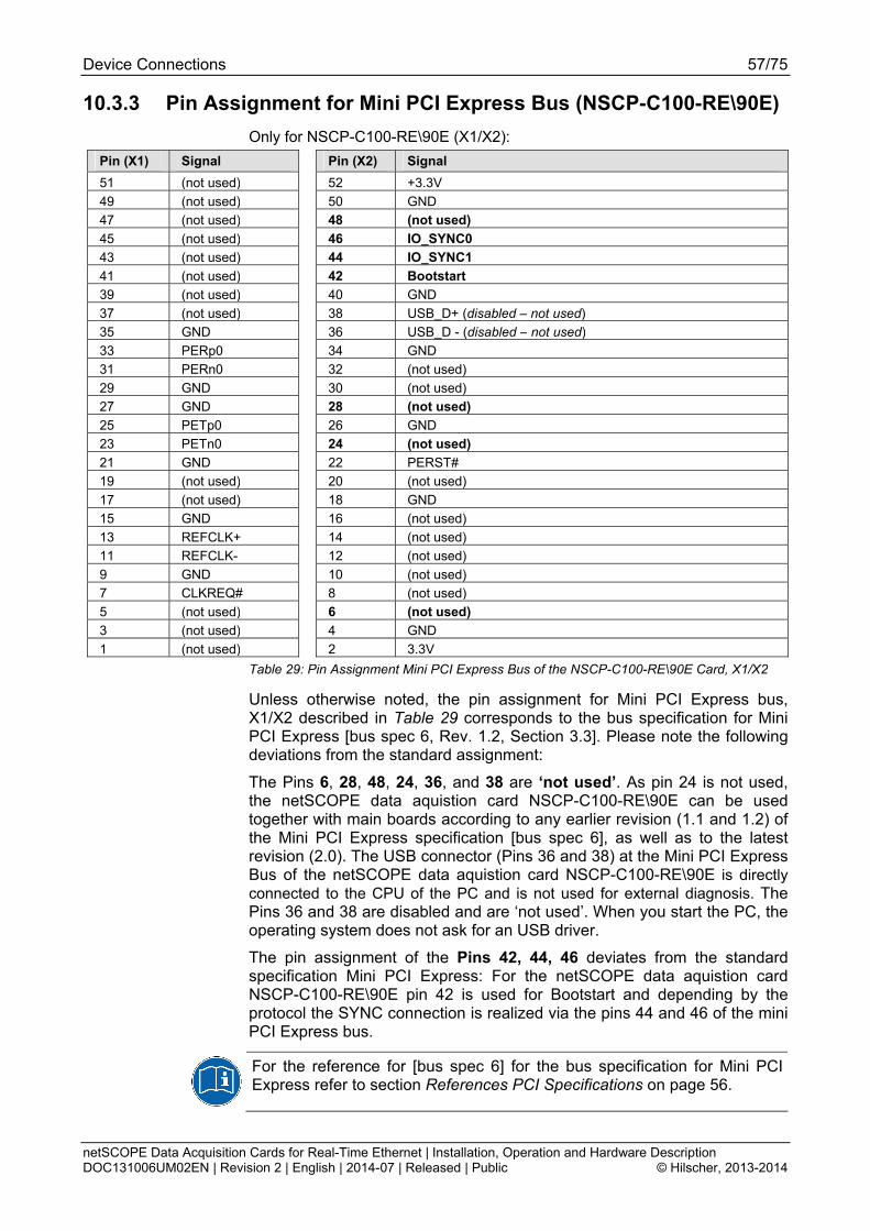
Device Connections 57/75
netSCOPE Data Acquisition Cards for Real-Time Ethernet | Installation, Operation and Hardware Description DOC131006UM02EN | Revision 2 | English | 2014-07 | Released | Public © Hilscher, 2013-2014
10.3.3 Pin Assignment for Mini PCI Express Bus (NSCP-C100-RE\90E)
Only for NSCP-C100-RE\90E (X1/X2):
Pin (X1) Signal Pin (X2) Signal
51 (not used) 52 +3.3V
49 (not used) 50 GND
47 (not used) 48 (not used)
45 (not used) 46 IO_SYNC0
43 (not used) 44 IO_SYNC1
41 (not used) 42 Bootstart
39 (not used) 40 GND
37 (not used) 38 USB_D+ (disabled – not used)
35 GND 36 USB_D - (disabled – not used)
33 PERp0 34 GND
31 PERn0 32 (not used)
29 GND 30 (not used)
27 GND 28 (not used)
25 PETp0 26 GND
23 PETn0 24 (not used)
21 GND 22 PERST#
19 (not used) 20 (not used)
17 (not used) 18 GND
15 GND 16 (not used)
13 REFCLK+ 14 (not used)
11 REFCLK- 12 (not used)
9 GND 10 (not used)
7 CLKREQ# 8 (not used)
5 (not used) 6 (not used)
3 (not used) 4 GND
1 (not used) 2 3.3V
Table 29: Pin Assignment Mini PCI Express Bus of the NSCP-C100-RE\90E Card, X1/X2
Unless otherwise noted, the pin assignment for Mini PCI Express bus, X1/X2 described in Table 29 corresponds to the bus specification for Mini PCI Express [bus spec 6, Rev. 1.2, Section 3.3]. Please note the following deviations from the standard assignment:
The Pins 6, 28, 48, 24, 36, and 38 are ‘not used’. As pin 24 is not used, the netSCOPE data aquistion card NSCP-C100-RE\90E can be used together with main boards according to any earlier revision (1.1 and 1.2) of the Mini PCI Express specification [bus spec 6], as well as to the latest revision (2.0). The USB connector (Pins 36 and 38) at the Mini PCI Express Bus of the netSCOPE data aquistion card NSCP-C100-RE\90E is directly connected to the CPU of the PC and is not used for external diagnosis. The Pins 36 and 38 are disabled and are ‘not used’. When you start the PC, the operating system does not ask for an USB driver.
The pin assignment of the Pins 42, 44, 46 deviates from the standard specification Mini PCI Express: For the netSCOPE data aquistion card NSCP-C100-RE\90E pin 42 is used for Bootstart and depending by the protocol the SYNC connection is realized via the pins 44 and 46 of the mini PCI Express bus.
For the reference for [bus spec 6] for the bus specification for Mini PCI Express refer to section References PCI Specifications on page 56.

Technical Data 58/75
netSCOPE Data Acquisition Cards for Real-Time Ethernet | Installation, Operation and Hardware Description DOC131006UM02EN | Revision 2 | English | 2014-07 | Released | Public © Hilscher, 2013-2014
11 Technical Data
11.1 Technical Data netSCOPE Data Acquisition Cards
Note: All technical data are temporarily and can be altered without notice.
11.1.1 NSCP-C100-RE\50
NSCP-C100-RE\50 Parameter Value
Name NSCP-C100-RE\50
Part No. 7330.100
Description netSCOPE data aquistion card PCI for Real-Time Ethernet
Part
Function Data Acquisition Card for Real-Time Ethernet
Communication Controller
Type netX 500 processor
RAM 8 MB SDRAM
FLASH 4 MB serial Flash EPROM
Integrated Memory
Size of the Dual-Port Memory 64 KByte
Bus Type PCI, according to [bus spec 1], refer to section Overview, page 56.
Transmission Rate 33 MHz
Data Access DPM
System Interface
Width for the data access to the Dual-Port Memory (DPM)
32-Bit
History depth and signal
count
Unlimited, only restricted by PC memory Process Data Interface
Signal types Input and output process values
EtherCAT Supported Real-Time Ethernet system
PROFINET IO
Ethernet Frame Types Ethernet II
Baud rate 100 MBit/s
Data transport layer Ethernet II, IEEE 802.3
Ethernet System
Automated symbol import EtherCAT: ENI file
Transmission rate 100 MBit/s
Interface Type 100 BASE-TX, refer to section Ethernet Interface, page 54.
Galvanic Isolation isolated
Isolation Voltage 1000 VDC (tested for 1 minute)
Full duplex supported (at 100 MBit/s)
Auto-Negotiation supported
Auto-Crossover supported
Connector 2* RJ45 Socket
Ethernet channels 2x RJ45, passive TAP, Ethernet delay < 1 µs
additional external TAP with zero-delay possible
Ethernet Interface
Time-stamp resolution 10 ns
SYS System Status LED
STA0 LED Status 0 (duo LED)
Display LED Display
STA1 LED Status 1 (duo LED)
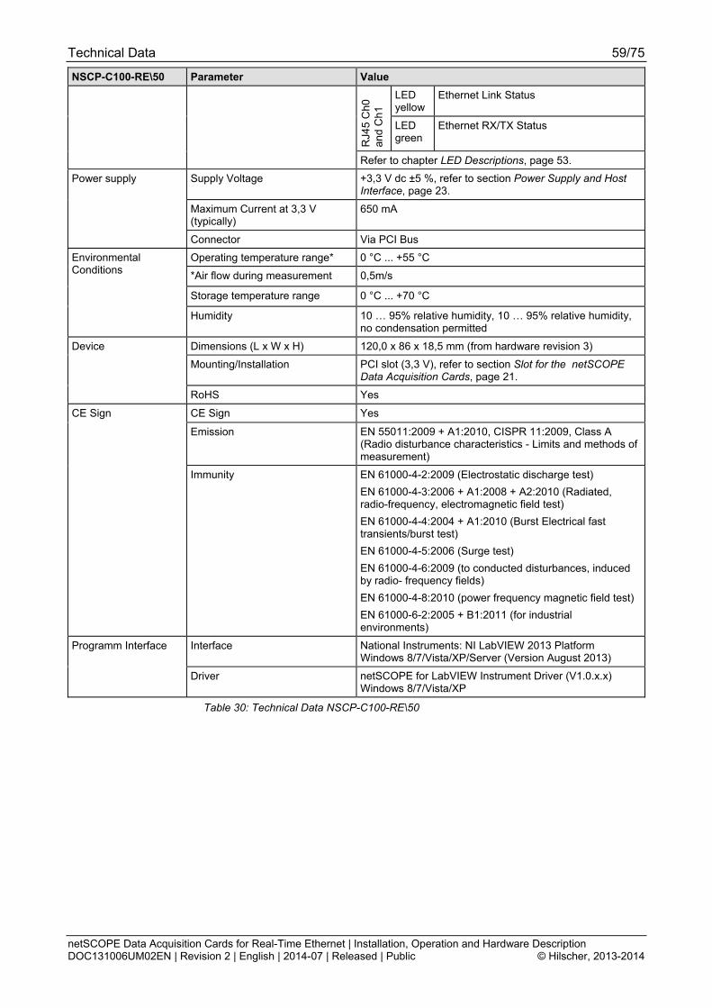
Technical Data 59/75
netSCOPE Data Acquisition Cards for Real-Time Ethernet | Installation, Operation and Hardware Description DOC131006UM02EN | Revision 2 | English | 2014-07 | Released | Public © Hilscher, 2013-2014
NSCP-C100-RE\50 Parameter Value
LED yellow
Ethernet Link Status
RJ4
5 C
h0
and
Ch1
LED green
Ethernet RX/TX Status
Refer to chapter LED Descriptions, page 53.
Supply Voltage +3,3 V dc ±5 %, refer to section Power Supply and Host Interface, page 23.
Maximum Current at 3,3 V (typically)
650 mA
Power supply
Connector Via PCI Bus
Operating temperature range* 0 °C ... +55 °C
*Air flow during measurement 0,5m/s
Storage temperature range 0 °C ... +70 °C
Environmental Conditions
Humidity 10 … 95% relative humidity, 10 … 95% relative humidity, no condensation permitted
Dimensions (L x W x H) 120,0 x 86 x 18,5 mm (from hardware revision 3)
Mounting/Installation PCI slot (3,3 V), refer to section Slot for the netSCOPE Data Acquisition Cards, page 21.
Device
RoHS Yes
CE Sign Yes
Emission EN 55011:2009 + A1:2010, CISPR 11:2009, Class A (Radio disturbance characteristics - Limits and methods of measurement)
CE Sign
Immunity EN 61000-4-2:2009 (Electrostatic discharge test)
EN 61000-4-3:2006 + A1:2008 + A2:2010 (Radiated, radio-frequency, electromagnetic field test)
EN 61000-4-4:2004 + A1:2010 (Burst Electrical fast transients/burst test)
EN 61000-4-5:2006 (Surge test)
EN 61000-4-6:2009 (to conducted disturbances, induced by radio- frequency fields)
EN 61000-4-8:2010 (power frequency magnetic field test)
EN 61000-6-2:2005 + B1:2011 (for industrial environments)
Interface National Instruments: NI LabVIEW 2013 Platform Windows 8/7/Vista/XP/Server (Version August 2013)
Programm Interface
Driver netSCOPE for LabVIEW Instrument Driver (V1.0.x.x) Windows 8/7/Vista/XP
Table 30: Technical Data NSCP-C100-RE\50

Technical Data 60/75
netSCOPE Data Acquisition Cards for Real-Time Ethernet | Installation, Operation and Hardware Description DOC131006UM02EN | Revision 2 | English | 2014-07 | Released | Public © Hilscher, 2013-2014
11.1.2 NSCP-C100-RE\50E
NSCP-C100-RE\50E Parameter Value
Name NSCP-C100-RE\50E
Part No. 7330.101
Description netSCOPE data aquistion card PCI Express for Real-Time Ethernet
Part
Function Data Acquisition Card for Real-Time Ethernet
Communication Controller
Type netX 500 processor
RAM 8 MB SDRAM
FLASH 4 MB serial Flash EPROM
Integrated Memory
Size of the Dual-Port Memory 64 KByte
Bus Type PCI Express, One Lane Port, according to [bus spec 2, Rev. 2.0] and [bus spec 3], refer to section Overview, page 56.
Transmission Rate 2 GBit/s
Data Access DPM
System Interface
Width for the data access to the Dual-Port Memory (DPM)
32-Bit
History depth and signal
count
Unlimited, only restricted by PC memory Process Data Interface
Signal types Input and output process values
EtherCAT Supported Real-Time Ethernet system PROFINET IO
Ethernet Frame Types Ethernet II
Baud rate 100 MBit/s
Data transport layer Ethernet II, IEEE 802.3
Ethernet system
Automated symbol import EtherCAT: ENI file
Transmission rate 100 MBit/s
Interface Type 100 BASE-TX, refer to section Ethernet Interface, page 54.
Galvanic Isolation isolated
Isolation Voltage 1000 VDC (tested for 1 minute)
Full duplex supported (at 100 MBit/s)
Auto-Negotiation supported
Auto-Crossover supported
Connector 2* RJ45 Socket
Ethernet channels 2x RJ45, passive TAP, Ethernet delay < 1 µs
additional external TAP with zero-delay possible
Ethernet Interface
Time-stamp resolution 10 ns
SYS System Status LED
STA0 LED Status 0 (duo LED)
STA1 LED Status 1 (duo LED)
LED yellow
Ethernet Link Status
RJ4
5 C
h0
and
Ch1
LED green
Ethernet RX/TX Status
Display LED Display
Refer to chapter LED Descriptions, page 53.

Technical Data 61/75
netSCOPE Data Acquisition Cards for Real-Time Ethernet | Installation, Operation and Hardware Description DOC131006UM02EN | Revision 2 | English | 2014-07 | Released | Public © Hilscher, 2013-2014
NSCP-C100-RE\50E Parameter Value
Supply Voltage +3,3 V dc ±5 %, refer to section Power Supply and Host Interface, page 23.
Maximum Current at 3,3 V (typically)
800 mA
Power supply
Connector Via PCI Express Bus
Operating temperature range* 0 °C ... +55 °C
*Air flow during measurement 0,5m/s
Storage temperature range 0 °C ... +70 °C
Environmental Conditions
Humidity 10 … 95% relative humidity, no condensation permitted
Dimensions (L x W x H) 120,0 x 86 x 18,5 mm (from hardware revision 4)
Mounting/Installation PCI Express x1 slot (3.3 V), refer to section Slot for the netSCOPE Data Acquisition Cards, page 21.
Device
RoHS Yes
CE Sign Yes
Emission EN 55011:2009 + A1:2010, CISPR 11:2009, Class A (Radio disturbance characteristics - Limits and methods of measurement)
CE Sign
Immunity EN 61000-4-2:2009 (Electrostatic discharge test)
EN 61000-4-3:2006 + A1:2008 + A2:2010 (Radiated, radio-frequency, electromagnetic field test)
EN 61000-4-4:2004 + A1:2010 (Burst Electrical fast transients/burst test)
EN 61000-4-5:2006 (Surge test)
EN 61000-4-6:2009 (to conducted disturbances, induced by radio- frequency fields)
EN 61000-4-8:2010 (power frequency magnetic field test)
EN 61000-6-2:2005 + B1:2011 (for industrial environments)
Interface National Instruments: NI LabVIEW 2013 Platform Windows 8/7/Vista/XP/Server (Version August 2013)
Programm Interface
Driver netSCOPE for LabVIEW Instrument Driver (V1.0.x.x) Windows 8/7/Vista/XP
Table 31: Technical Data NSCP-C100-RE\50E

Technical Data 62/75
netSCOPE Data Acquisition Cards for Real-Time Ethernet | Installation, Operation and Hardware Description DOC131006UM02EN | Revision 2 | English | 2014-07 | Released | Public © Hilscher, 2013-2014
11.1.3 NSCP-C100-RE\70E
NSCP-C100-RE\70E Parameter Value
Name NSCP-C100-RE\70E
Part No. 7330.102
Description netSCOPE data aquistion card Low Profile PCI Express for Real-Time-Ethernet (Low Profile PCIe with RTE)
Part
Function Data Acquisition Card for Real-Time Ethernet
Communication Controller
Type netX 100 processor
RAM 8 MB SDRAM
FLASH 4 MB serial Flash EPROM
Integrated Memory
Size of the Dual-Port Memory 64 KByte
Bus Type PCI Express, One Lane Port, according to [bus spec 2, Rev. 2.0] and [bus spec 3], refer to section Overview, page 56.
Transmission Rate 2 GBit/s
Data Access DPM or DMA (Direct Memory Access)
System Interface
Width for the data access to the Dual-Port Memory (DPM)
32-Bit
History depth and signal
count
Unlimited, only restricted by PC memory Process Data Interface
Signal types Input and output process values
EtherCAT Supported Real-Time Ethernet system PROFINET IO
Ethernet Frame Types Ethernet II
Baud rate 100 MBit/s
Data transport layer Ethernet II, IEEE 802.3
Ethernet system
Automated symbol import EtherCAT: ENI file
Transmission rate 100 MBit/s
Interface Type 100 BASE-TX, refer to section Ethernet Interface, page 54.
Galvanic Isolation isolated
Isolation Voltage 1000 VDC (tested for 1 minute)
Full duplex supported (at 100 MBit/s)
Auto-Negotiation supported
Auto-Crossover supported
Connector 2* RJ45 Socket
Ethernet channels 2x RJ45, passive TAP, Ethernet delay < 1 µs
additional external TAP with zero-delay possible
Ethernet Interface
Time-stamp resolution 10 ns
SYS System Status LED
STA0 LED Status 0 (duo LED)
STA1 LED Status 1 (duo LED)
LED yellow
Ethernet Link Status
RJ4
5 C
h0
and
Ch1
LED green
Ethernet RX/TX Status
Display LED Display
Refer to chapter LED Descriptions, page 53.

Technical Data 63/75
netSCOPE Data Acquisition Cards for Real-Time Ethernet | Installation, Operation and Hardware Description DOC131006UM02EN | Revision 2 | English | 2014-07 | Released | Public © Hilscher, 2013-2014
NSCP-C100-RE\70E Parameter Value
Supply Voltage +3,3 V dc ±5 %, refer to section Power Supply and Host Interface, page 23.
Maximum Current at 3,3 V (typically)
800 mA
Power supply
Connector Via PCI Express Bus
Operating temperature range* 0 °C ... +65 °C
*Air flow during measurement 0,5m/s
Storage temperature range 0 °C ... +70 °C
Environmental Conditions
Humidity 10 … 95% relative humidity, no condensation permitted
Dimensions (L x W x H) 119,0 x 69,0 x 18,5 mm
Mounting/Installation PCI Express x4 slot (3.3 V), refer to section Slot for the netSCOPE Data Acquisition Cards, page 21.
Device
RoHS Yes
CE Sign Yes
Emission EN 55011:2009 + A1:2010, CISPR 11:2009, Class A (Radio disturbance characteristics - Limits and methods of measurement)
CE Sign
Immunity EN 61000-4-2:2009 (Electrostatic discharge test)
EN 61000-4-3:2006 + A1:2008 + A2:2010 (Radiated, radio-frequency, electromagnetic field test)
EN 61000-4-4:2004 + A1:2010 (Burst Electrical fast transients/burst test)
EN 61000-4-5:2006 (Surge test)
EN 61000-4-6:2009 (to conducted disturbances, induced by radio- frequency fields)
EN 61000-4-8:2010 (power frequency magnetic field test)
EN 61000-6-2:2005 + B1:2011 (for industrial environments)
Interface National Instruments: NI LabVIEW 2013 Platform Windows 8/7/Vista/XP/Server (Version August 2013)
Programm Interface
Driver netSCOPE for LabVIEW Instrument Driver (V1.0.x.x) Windows 8/7/Vista/XP
Table 32: Technical Data NSCP-C100-RE\70E

Technical Data 64/75
netSCOPE Data Acquisition Cards for Real-Time Ethernet | Installation, Operation and Hardware Description DOC131006UM02EN | Revision 2 | English | 2014-07 | Released | Public © Hilscher, 2013-2014
11.1.4 NSCP-C100-RE\80
NSCP-C100-RE\80 Parameter Value
Name NSCP-C100-RE\80
Part No. 7330.103
Description netSCOPE data aquistion card Compact PCI for for Real-Time Ethernet Master or Slave
Part
Function Data Acquisition Card for Real-Time Ethernet
Communication Controller
Type netX 100 processor
RAM 8 MB SDRAM
FLASH 4 MB serial Flash EPROM
Integrated Memory
Size of the Dual-Port Memory 64 KByte
Bus Type Compact PCI, according to [bus spec 4], refer to section Overview, page 56.
Transmission Rate 33 MHz
Data Access DPM or DMA (Direct Memory Access)
System Interface
Width for the data access to the Dual-Port Memory (DPM)
32-Bit
History depth and signal
count
Unlimited, only restricted by PC memory Process Data Interface
Signal types Input and output process values
EtherCAT Supported Real-Time Ethernet system PROFINET IO
Ethernet Frame Types Ethernet II
Baud rate 100 MBit/s
Data transport layer Ethernet II, IEEE 802.3
Ethernet System
Automated symbol import EtherCAT: ENI file
Transmission rate 100 MBit/s
Interface Type 100 BASE-TX, refer to section Ethernet Interface, page 54.
Galvanic Isolation isolated
Isolation Voltage 1000 VDC (tested for 1 minute)
Full duplex supported (at 100 MBit/s)
Auto-Negotiation supported
Auto-Crossover supported
Connector 2* RJ45 Socket
Ethernet channels 2x RJ45, passive TAP, Ethernet delay < 1 µs
additional external TAP with zero-delay possible
Ehernet Interface
Time-stamp resolution 10 ns
Diagnostic Interface USB Interface Not used.
SYS System Status LED
STA0 LED Status 0 (duo LED)
STA1 LED Status 1 (duo LED)
LED yellow
Ethernet Link Status
RJ4
5 C
h0
and
Ch1
LED green
Ethernet RX/TX Status
Display LED Display
Refer to chapter LED Descriptions, page 53.
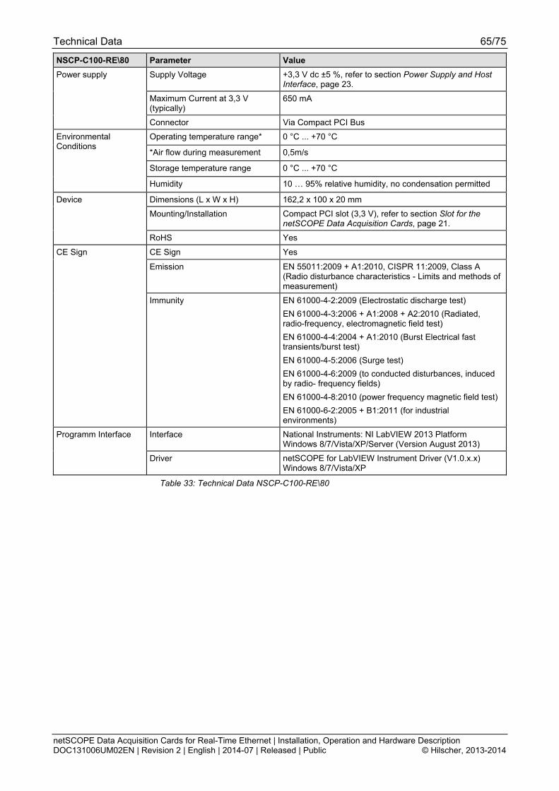
Technical Data 65/75
netSCOPE Data Acquisition Cards for Real-Time Ethernet | Installation, Operation and Hardware Description DOC131006UM02EN | Revision 2 | English | 2014-07 | Released | Public © Hilscher, 2013-2014
NSCP-C100-RE\80 Parameter Value
Supply Voltage +3,3 V dc ±5 %, refer to section Power Supply and Host Interface, page 23.
Maximum Current at 3,3 V (typically)
650 mA
Power supply
Connector Via Compact PCI Bus
Operating temperature range* 0 °C ... +70 °C
*Air flow during measurement 0,5m/s
Storage temperature range 0 °C ... +70 °C
Environmental Conditions
Humidity 10 … 95% relative humidity, no condensation permitted
Dimensions (L x W x H) 162,2 x 100 x 20 mm
Mounting/Installation Compact PCI slot (3,3 V), refer to section Slot for the netSCOPE Data Acquisition Cards, page 21.
Device
RoHS Yes
CE Sign Yes
Emission EN 55011:2009 + A1:2010, CISPR 11:2009, Class A (Radio disturbance characteristics - Limits and methods of measurement)
CE Sign
Immunity EN 61000-4-2:2009 (Electrostatic discharge test)
EN 61000-4-3:2006 + A1:2008 + A2:2010 (Radiated, radio-frequency, electromagnetic field test)
EN 61000-4-4:2004 + A1:2010 (Burst Electrical fast transients/burst test)
EN 61000-4-5:2006 (Surge test)
EN 61000-4-6:2009 (to conducted disturbances, induced by radio- frequency fields)
EN 61000-4-8:2010 (power frequency magnetic field test)
EN 61000-6-2:2005 + B1:2011 (for industrial environments)
Interface National Instruments: NI LabVIEW 2013 Platform Windows 8/7/Vista/XP/Server (Version August 2013)
Programm Interface
Driver netSCOPE for LabVIEW Instrument Driver (V1.0.x.x) Windows 8/7/Vista/XP
Table 33: Technical Data NSCP-C100-RE\80

Technical Data 66/75
netSCOPE Data Acquisition Cards for Real-Time Ethernet | Installation, Operation and Hardware Description DOC131006UM02EN | Revision 2 | English | 2014-07 | Released | Public © Hilscher, 2013-2014
11.1.5 NSCP-C100-RE\90E
NSCP-C100-RE\90E Parameter Value
Name NSCP-C100-RE\90E
Part No. 7330.105
Description netSCOPE data aquistion card Mini PCI Express for for Real-Time Ethernet - with cable connector Ethernet for Ethernet assembly interface (AIFX-RE) Note: The device height and the power input of the netSCOPE data aquistion card Mini PCI Express NSCP-C100-RE\90E do not comply with the standard specifications.
Part
Function Data Acquisition Card for Real-Time Ethernet
Communication Controller
Type netX 100 processor
RAM 8 MB SDRAM
FLASH 4 MB serial Flash EPROM
Integrated Memory
Size of the Dual-Port Memory 64 KByte
Bus Type Mini PCI Express, One Lane Port, according to [bus spec 2], refer to section Overview, page 56 and Pin Assignment for Mini PCI Express Bus, page 57.
Transmission Rate 33 MHz
Data Access DPM or DMA (Direct Memory Access)
System Interface
Width for the data access to the Dual-Port Memory (DPM)
32-Bit
History depth and signal
count
Unlimited, only restricted by PC memory Process Data Interface
Signal types Input and output process values
EtherCAT Supported Real-Time Ethernet system PROFINET IO
Ethernet Frame Types Ethernet II
Baud rate 100 MBit/s
Data transport layer Ethernet II, IEEE 802.3
Ethernet System
Automated symbol import EtherCAT: ENI file
Transmission Rate 100 MBit/s
Interface Type 100 BASE-TX, refer to section Ethernet Interface, page 54.
Full duplex supported (at 100 MBit/s)
Auto-Negotiation supported
Auto-Crossover supported
Ethernet Assembly Interface AIFX-RE, refer to section AIFX-RE, page 68. Important! Operating the netSCOPE data aquistion card NSCP-C100-RE\90E requires proper connection of the Ethernet assembly interface (AIFX-RE) to the basic card!
Connector AIFX-RE Cable Connector Ethernet X4 (JST BM20B-SRDS-G-TFC, Pitch 1,0 mm)
Ethernet Interface
Time-stamp resolution 10 ns
Display LED Display SYS System Status LED
Supply Voltage +3,3 V dc ±5 %, refer to section Power Supply and Host Interface, page 23.
Maximum Current at at 3,3 V (typically)
800 mA
Power supply
Connector Via Mini PCI Express Bus
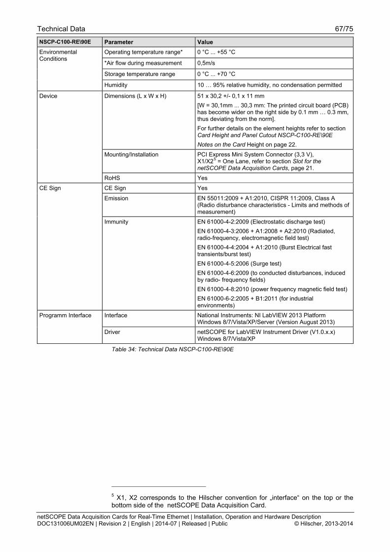
Technical Data 67/75
netSCOPE Data Acquisition Cards for Real-Time Ethernet | Installation, Operation and Hardware Description DOC131006UM02EN | Revision 2 | English | 2014-07 | Released | Public © Hilscher, 2013-2014
NSCP-C100-RE\90E Parameter Value
Operating temperature range* 0 °C ... +55 °C
*Air flow during measurement 0,5m/s
Storage temperature range 0 °C ... +70 °C
Environmental Conditions
Humidity 10 … 95% relative humidity, no condensation permitted
Dimensions (L x W x H) 51 x 30,2 +/- 0,1 x 11 mm
[W = 30,1mm ... 30,3 mm: The printed circuit board (PCB) has become wider on the right side by 0.1 mm … 0.3 mm, thus deviating from the norm].
For further details on the element heights refer to section Card Height and Panel Cutout NSCP-C100-RE\90E
Notes on the Card Height on page 22.
Mounting/Installation PCI Express Mini System Connector (3,3 V), X1/X25 = One Lane, refer to section Slot for the netSCOPE Data Acquisition Cards, page 21.
Device
RoHS Yes
CE Sign Yes
Emission EN 55011:2009 + A1:2010, CISPR 11:2009, Class A (Radio disturbance characteristics - Limits and methods of measurement)
CE Sign
Immunity EN 61000-4-2:2009 (Electrostatic discharge test)
EN 61000-4-3:2006 + A1:2008 + A2:2010 (Radiated, radio-frequency, electromagnetic field test)
EN 61000-4-4:2004 + A1:2010 (Burst Electrical fast transients/burst test)
EN 61000-4-5:2006 (Surge test)
EN 61000-4-6:2009 (to conducted disturbances, induced by radio- frequency fields)
EN 61000-4-8:2010 (power frequency magnetic field test)
EN 61000-6-2:2005 + B1:2011 (for industrial environments)
Interface National Instruments: NI LabVIEW 2013 Platform Windows 8/7/Vista/XP/Server (Version August 2013)
Programm Interface
Driver netSCOPE for LabVIEW Instrument Driver (V1.0.x.x) Windows 8/7/Vista/XP
Table 34: Technical Data NSCP-C100-RE\90E
5 X1, X2 corresponds to the Hilscher convention for „interface“ on the top or the bottom side of the netSCOPE Data Acquisition Card.
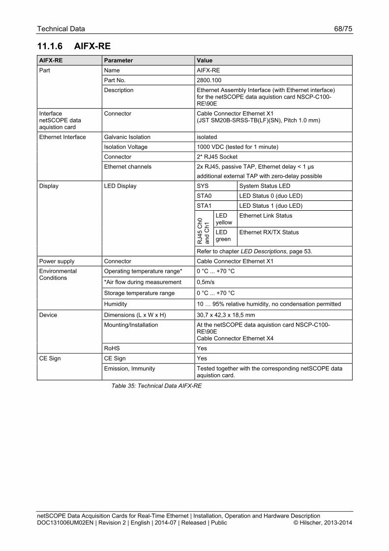
Technical Data 68/75
netSCOPE Data Acquisition Cards for Real-Time Ethernet | Installation, Operation and Hardware Description DOC131006UM02EN | Revision 2 | English | 2014-07 | Released | Public © Hilscher, 2013-2014
11.1.6 AIFX-RE
AIFX-RE Parameter Value
Name AIFX-RE
Part No. 2800.100
Part
Description Ethernet Assembly Interface (with Ethernet interface) for the netSCOPE data aquistion card NSCP-C100-RE\90E
Interface netSCOPE data aquistion card
Connector Cable Connector Ethernet X1 (JST SM20B-SRSS-TB(LF)(SN), Pitch 1.0 mm)
Galvanic Isolation isolated
Isolation Voltage 1000 VDC (tested for 1 minute)
Connector 2* RJ45 Socket
Ethernet Interface
Ethernet channels 2x RJ45, passive TAP, Ethernet delay < 1 µs
additional external TAP with zero-delay possible
SYS System Status LED
STA0 LED Status 0 (duo LED)
STA1 LED Status 1 (duo LED)
LED yellow
Ethernet Link Status
RJ4
5 C
h0
and
Ch1
LED green
Ethernet RX/TX Status
Display LED Display
Refer to chapter LED Descriptions, page 53.
Power supply Connector Cable Connector Ethernet X1
Operating temperature range* 0 °C ... +70 °C
*Air flow during measurement 0,5m/s
Storage temperature range 0 °C ... +70 °C
Environmental Conditions
Humidity 10 … 95% relative humidity, no condensation permitted
Dimensions (L x W x H) 30,7 x 42,3 x 18,5 mm
Mounting/Installation At the netSCOPE data aquistion card NSCP-C100-RE\90E Cable Connector Ethernet X4
Device
RoHS Yes
CE Sign Yes CE Sign
Emission, Immunity Tested together with the corresponding netSCOPE data aquistion card.
Table 35: Technical Data AIFX-RE
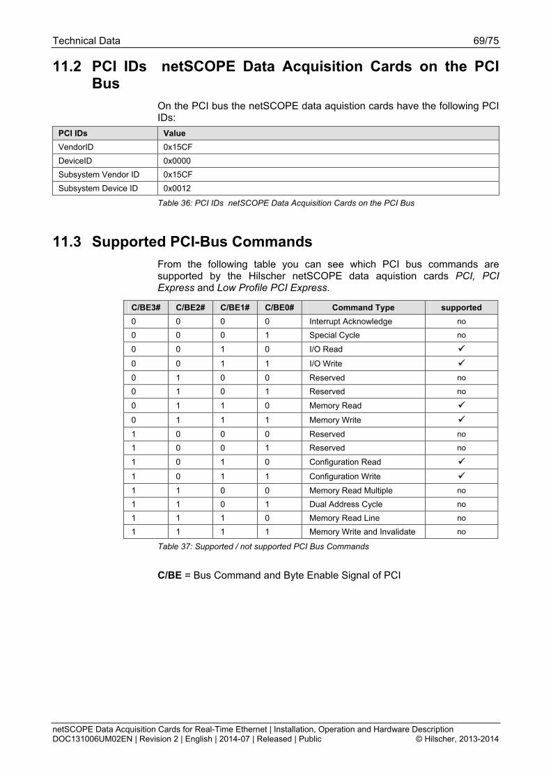
Technical Data 69/75
netSCOPE Data Acquisition Cards for Real-Time Ethernet | Installation, Operation and Hardware Description DOC131006UM02EN | Revision 2 | English | 2014-07 | Released | Public © Hilscher, 2013-2014
11.2 PCI IDs netSCOPE Data Acquisition Cards on the PCI Bus
On the PCI bus the netSCOPE data aquistion cards have the following PCI IDs:
PCI IDs Value
VendorID 0x15CF
DeviceID 0x0000
Subsystem Vendor ID 0x15CF
Subsystem Device ID 0x0012
Table 36: PCI IDs netSCOPE Data Acquisition Cards on the PCI Bus
11.3 Supported PCI-Bus Commands
From the following table you can see which PCI bus commands are supported by the Hilscher netSCOPE data aquistion cards PCI, PCI Express and Low Profile PCI Express.
C/BE3# C/BE2# C/BE1# C/BE0# Command Type supported
0 0 0 0 Interrupt Acknowledge no
0 0 0 1 Special Cycle no
0 0 1 0 I/O Read
0 0 1 1 I/O Write
0 1 0 0 Reserved no
0 1 0 1 Reserved no
0 1 1 0 Memory Read
0 1 1 1 Memory Write
1 0 0 0 Reserved no
1 0 0 1 Reserved no
1 0 1 0 Configuration Read
1 0 1 1 Configuration Write
1 1 0 0 Memory Read Multiple no
1 1 0 1 Dual Address Cycle no
1 1 1 0 Memory Read Line no
1 1 1 1 Memory Write and Invalidate no
Table 37: Supported / not supported PCI Bus Commands
C/BE = Bus Command and Byte Enable Signal of PCI

Annex 70/75
netSCOPE Data Acquisition Cards for Real-Time Ethernet | Installation, Operation and Hardware Description DOC131006UM02EN | Revision 2 | English | 2014-07 | Released | Public © Hilscher, 2013-2014
12 Annex
12.1 Matrix Label
A matrix label is on the device. It contains 3 items:
1. Part number
2. Hardware Revision
3. Serial number
The figure shows part number 7330.105, hardware revision 1 and serial number 22394.
Part number
Hardware Revision
Serial number
Figure 35: Matrix Label
12.2 Disposal of Waste Electronic Equipment
According to the European Directive 2002/96/EG “Waste Electrical and Electronic Equipment (WEEE)”, waste electronic equipment may not be disposed of as household waste. As a consumer, you are legally obliged to dispose of all waste electronic equipment according to national and local regulations.
Waste Electronic Equipment
This product must not be treated as household waste.
This product must be disposed of at a designated waste electronic equipment collecting point.
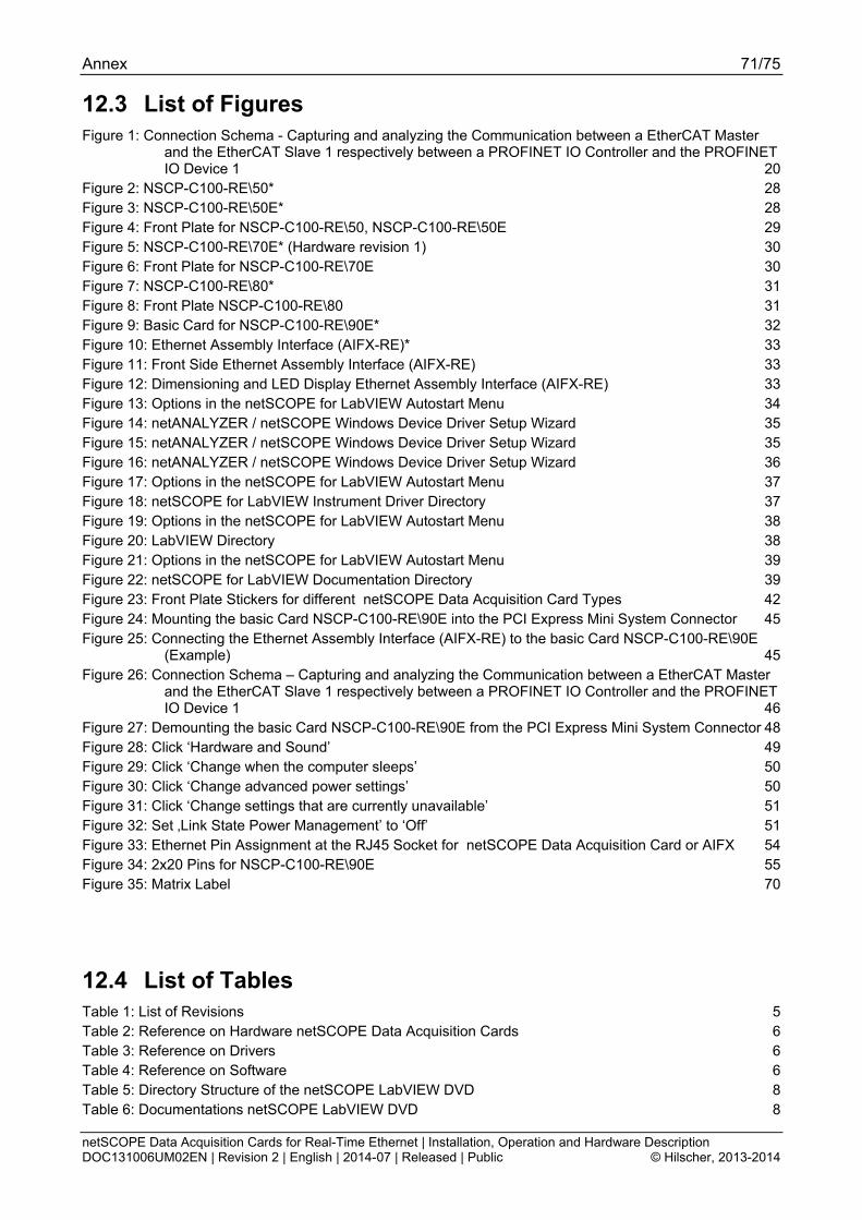
Annex 71/75
netSCOPE Data Acquisition Cards for Real-Time Ethernet | Installation, Operation and Hardware Description DOC131006UM02EN | Revision 2 | English | 2014-07 | Released | Public © Hilscher, 2013-2014
12.3 List of Figures Figure 1: Connection Schema - Capturing and analyzing the Communication between a EtherCAT Master
and the EtherCAT Slave 1 respectively between a PROFINET IO Controller and the PROFINET IO Device 1 20
Figure 2: NSCP-C100-RE\50* 28 Figure 3: NSCP-C100-RE\50E* 28 Figure 4: Front Plate for NSCP-C100-RE\50, NSCP-C100-RE\50E 29 Figure 5: NSCP-C100-RE\70E* (Hardware revision 1) 30 Figure 6: Front Plate for NSCP-C100-RE\70E 30 Figure 7: NSCP-C100-RE\80* 31 Figure 8: Front Plate NSCP-C100-RE\80 31 Figure 9: Basic Card for NSCP-C100-RE\90E* 32 Figure 10: Ethernet Assembly Interface (AIFX-RE)* 33 Figure 11: Front Side Ethernet Assembly Interface (AIFX-RE) 33 Figure 12: Dimensioning and LED Display Ethernet Assembly Interface (AIFX-RE) 33 Figure 13: Options in the netSCOPE for LabVIEW Autostart Menu 34 Figure 14: netANALYZER / netSCOPE Windows Device Driver Setup Wizard 35 Figure 15: netANALYZER / netSCOPE Windows Device Driver Setup Wizard 35 Figure 16: netANALYZER / netSCOPE Windows Device Driver Setup Wizard 36 Figure 17: Options in the netSCOPE for LabVIEW Autostart Menu 37 Figure 18: netSCOPE for LabVIEW Instrument Driver Directory 37 Figure 19: Options in the netSCOPE for LabVIEW Autostart Menu 38 Figure 20: LabVIEW Directory 38 Figure 21: Options in the netSCOPE for LabVIEW Autostart Menu 39 Figure 22: netSCOPE for LabVIEW Documentation Directory 39 Figure 23: Front Plate Stickers for different netSCOPE Data Acquisition Card Types 42 Figure 24: Mounting the basic Card NSCP-C100-RE\90E into the PCI Express Mini System Connector 45 Figure 25: Connecting the Ethernet Assembly Interface (AIFX-RE) to the basic Card NSCP-C100-RE\90E
(Example) 45 Figure 26: Connection Schema – Capturing and analyzing the Communication between a EtherCAT Master
and the EtherCAT Slave 1 respectively between a PROFINET IO Controller and the PROFINET IO Device 1 46
Figure 27: Demounting the basic Card NSCP-C100-RE\90E from the PCI Express Mini System Connector 48 Figure 28: Click ‘Hardware and Sound’ 49 Figure 29: Click ‘Change when the computer sleeps’ 50 Figure 30: Click ‘Change advanced power settings’ 50 Figure 31: Click ‘Change settings that are currently unavailable’ 51 Figure 32: Set ‚Link State Power Management’ to ‘Off’ 51 Figure 33: Ethernet Pin Assignment at the RJ45 Socket for netSCOPE Data Acquisition Card or AIFX 54 Figure 34: 2x20 Pins for NSCP-C100-RE\90E 55 Figure 35: Matrix Label 70
12.4 List of Tables Table 1: List of Revisions 5 Table 2: Reference on Hardware netSCOPE Data Acquisition Cards 6 Table 3: Reference on Drivers 6 Table 4: Reference on Software 6 Table 5: Directory Structure of the netSCOPE LabVIEW DVD 8 Table 6: Documentations netSCOPE LabVIEW DVD 8
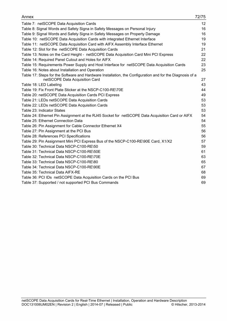
Annex 72/75
netSCOPE Data Acquisition Cards for Real-Time Ethernet | Installation, Operation and Hardware Description DOC131006UM02EN | Revision 2 | English | 2014-07 | Released | Public © Hilscher, 2013-2014
Table 7: netSCOPE Data Acquisition Cards 12 Table 8: Signal Words and Safety Signa in Safety Messages on Personal Injury 16 Table 9: Signal Words and Safety Signa in Safety Messages on Property Damage 16 Table 10: netSCOPE Data Acquisition Cards with integrated Ethernet Interface 19 Table 11: netSCOPE Data Acquisition Card with AIFX Assembly Interface Ethernet 19 Table 12: Slot for the netSCOPE Data Acquisition Cards 21 Table 13: Notes on the Card Height - netSCOPE Data Acquisition Card Mini PCI Express 22 Table 14: Required Panel Cutout and Holes for AIFX 22 Table 15: Requirements Power Supply and Host Interface for netSCOPE Data Acquisition Cards 23 Table 16: Notes about Installation and Operation 25 Table 17: Steps for the Software and Hardware Installation, the Configuration and for the Diagnosis of a
netSCOPE Data Acquisition Card 27 Table 18: LED Labeling 43 Table 19: Fix Front Plate Sticker at the NSCP-C100-RE\70E 44 Table 20: netSCOPE Data Acquisition Cards PCI Express 49 Table 21: LEDs netSCOPE Data Acquisition Cards 53 Table 22: LEDs netSCOPE Data Acquisition Cards 53 Table 23: Indicator States 53 Table 24: Ethernet Pin Assignment at the RJ45 Socket for netSCOPE Data Acquisition Card or AIFX 54 Table 25: Ethernet Connection Data 54 Table 26: Pin Assignment for Cable Connector Ethernet X4 55 Table 27: Pin Assignment at the PCI Bus 56 Table 28: References PCI Specifications 56 Table 29: Pin Assignment Mini PCI Express Bus of the NSCP-C100-RE\90E Card, X1/X2 57 Table 30: Technical Data NSCP-C100-RE\50 59 Table 31: Technical Data NSCP-C100-RE\50E 61 Table 32: Technical Data NSCP-C100-RE\70E 63 Table 33: Technical Data NSCP-C100-RE\80 65 Table 34: Technical Data NSCP-C100-RE\90E 67 Table 35: Technical Data AIFX-RE 68 Table 36: PCI IDs netSCOPE Data Acquisition Cards on the PCI Bus 69 Table 37: Supported / not supported PCI Bus Commands 69
Annex 73/75
netSCOPE Data Acquisition Cards for Real-Time Ethernet | Installation, Operation and Hardware Description DOC131006UM02EN | Revision 2 | English | 2014-07 | Released | Public © Hilscher, 2013-2014
12.5 Glossary
100-Base TX
Standard for communication on Ethernet over unshielded twisted pair lines with RJ45 connectors and a baud rate of 100 MBit/s according to the IEEE 802. specification
Auto-Crossover
Auto-Crossover is a feature of an interface: An interface with Auto-Crossover capability will automatically detect and correct if the data lines have been exchanged vice versa.
Auto-Negotiation
Auto-Negotiation is a feature of an interface: An interface with Auto- Negotiation will automatically determine a set of correct communication parameters.
Baud rate
Data transmission speed of a communication channel or interface.
Boot loader
Program loading the firmware into the memory of a device in order to be executed.
Device Description File
A file containing configuration information about a device being a part of a network that can be read out by masters for system configuration. Device Description Files use various formats which depend on the communication system.
EtherCAT
A communication system for industrial Ethernet designed and developed by Beckhoff Automation GmbH.
Firmware
Software running inside a device providing the basic functionality of this device. The firmware is stored remanently in the flash memory circuit of the device. It can be updated by a firmware download.
Full duplex
Full duplex denominates a telecommunication system between two communication partners which allows simultaneous communication in both directions is called a full-duplex telecommunication system. At such a system, it will be possible to transmit data even if currently data are received. Full-duplex is the opposite of Half_duplex.
telecommunication system. At such a system, receiving data inhibits the transmission of data. Half-duplex is the opposite of _Full_duplex.
Industrial Ethernet
See Real-Time Ethernet

Annex 74/75
netSCOPE Data Acquisition Cards for Real-Time Ethernet | Installation, Operation and Hardware Description DOC131006UM02EN | Revision 2 | English | 2014-07 | Released | Public © Hilscher, 2013-2014
LabVIEW
Laboratory Virtual Instrumentation Engineering Workbench
netSCOPE
Hilscher's netSCOPE is a tool to capture network traffic from Real-Time Ethernet systems and to display data content for analysis purposes.
netX
networX on chip, next generation of communication controllers
PCB
Printed Circuit Board, (printed = machine-made) circuit board
PCIe
Abbreviation for PCI Express
PROFINET
A communication system for Industrial Ethernet designed and developed by PROFIBUS & PROFINET International (PI). It uses some mechanisms similar to those of the PROFIBUS field bus.
RE
RE stands for Real-Time Ethernet
Real-Time Ethernet
Real-Time Ethernet (Industrial Ethernet) is an extension of the Ethernet networking technology for industrial purposes with very good real-time features and performance. There is a variety of different Real-Time Ethernet systems on the market (e. g. EtherCAT) which are incompatible with each other.
RJ45
A connector type often used for Ethernet connection. It has been standardized by the Federal Communications Commission of the USA (FCC).

Annex 75/75
netSCOPE Data Acquisition Cards for Real-Time Ethernet | Installation, Operation and Hardware Description DOC131006UM02EN | Revision 2 | English | 2014-07 | Released | Public © Hilscher, 2013-2014
12.6 Contacts
Headquarters
Germany Hilscher Gesellschaft für Systemautomation mbH Rheinstrasse 15 65795 Hattersheim Phone: +49 (0) 6190 9907-0 Fax: +49 (0) 6190 9907-50 E-Mail: [email protected]
Support Phone: +49 (0) 6190 9907-99 E-Mail: [email protected]
Subsidiaries
China Hilscher Systemautomation (Shanghai) Co. Ltd. 200010 Shanghai Phone: +86 (0) 21-6355-5161 E-Mail: [email protected]
Support Phone: +86 (0) 21-6355-5161 E-Mail: [email protected]
France Hilscher France S.a.r.l. 69500 Bron Phone: +33 (0) 4 72 37 98 40 E-Mail: [email protected]
Support Phone: +33 (0) 4 72 37 98 40 E-Mail: [email protected]
India Hilscher India Pvt. Ltd. New Delhi - 110 065 Phone: +91 11 26915430 E-Mail: [email protected]
Italy Hilscher Italia S.r.l. 20090 Vimodrone (MI) Phone: +39 02 25007068 E-Mail: [email protected]
Support Phone: +39 02 25007068 E-Mail: [email protected]
Japan Hilscher Japan KK Tokyo, 160-0022 Phone: +81 (0) 3-5362-0521 E-Mail: [email protected]
Support Phone: +81 (0) 3-5362-0521 E-Mail: [email protected]
Korea Hilscher Korea Inc. Seongnam, Gyeonggi, 463-400 Phone: +82 (0) 31-789-3715 E-Mail: [email protected]
Switzerland Hilscher Swiss GmbH 4500 Solothurn Phone: +41 (0) 32 623 6633 E-Mail: [email protected]
Support Phone: +49 (0) 6190 9907-99 E-Mail: [email protected]
USA Hilscher North America, Inc. Lisle, IL 60532 Phone: +1 630-505-5301 E-Mail: [email protected]
Support Phone: +1 630-505-5301 E-Mail: [email protected]