netra™ ct server system administration guideheas/sun-feh-2_1/collections/816/816-2483/pdf/... ·...
TRANSCRIPT

Sun Microsystems, Inc.4150 Network CircleSanta Clara, CA 95054 U.S.A.650-960-1300
Send comments about this document to: [email protected]
Netra™ CT Server SystemAdministration Guide
For the Netra CT 810 Server and Netra CT 410 Server
Part No. 816-2483-10October 2002, Revision A

Copyright 2002 Sun Microsystems, Inc., 4150 Network Circle, Santa Clara, California 95054, U.S.A. All rights reserved.
Sun Microsystems, Inc. has intellectual property rights relating to technology embodied in the product that is described in this document. Inparticular, and without limitation, these intellectual property rights may include one or more of the U.S. patents listed athttp://www.sun.com/patents and one or more additional patents or pending patent applications in the U.S. and in other countries.
This document and the product to which it pertains are distributed under licenses restricting their use, copying, distribution, anddecompilation. No part of the product or of this document may be reproduced in any form by any means without prior written authorization ofSun and its licensors, if any.
Third-party software, including font technology, is copyrighted and licensed from Sun suppliers.
Parts of the product may be derived from Berkeley BSD systems, licensed from the University of California. UNIX is a registered trademark inthe U.S. and in other countries, exclusively licensed through X/Open Company, Ltd.
Sun, Sun Microsystems, the Sun logo, AnswerBook2, docs.sun.com, Netra, ChorusOS, OpenBoot, Java, and Solaris are trademarks or registeredtrademarks of Sun Microsystems, Inc. in the U.S. and in other countries.
All SPARC trademarks are used under license and are trademarks or registered trademarks of SPARC International, Inc. in the U.S. and in othercountries. Products bearing SPARC trademarks are based upon an architecture developed by Sun Microsystems, Inc.
The OPEN LOOK and Sun™ Graphical User Interface was developed by Sun Microsystems, Inc. for its users and licensees. Sun acknowledgesthe pioneering efforts of Xerox in researching and developing the concept of visual or graphical user interfaces for the computer industry. Sunholds a non-exclusive license from Xerox to the Xerox Graphical User Interface, which license also covers Sun’s licensees who implement OPENLOOK GUIs and otherwise comply with Sun’s written license agreements.
Use, duplication, or disclosure by the U.S. Government is subject to restrictions set forth in the Sun Microsystems, Inc. license agreements and asprovided in DFARS 227.7202-1(a) and 227.7202-3(a) (1995), DFARS 252.227-7013(c)(1)(ii) (Oct. 1998), FAR 12.212(a) (1995), FAR 52.227-19, orFAR 52.227-14 (ALT III), as applicable.
DOCUMENTATION IS PROVIDED "AS IS" AND ALL EXPRESS OR IMPLIED CONDITIONS, REPRESENTATIONS AND WARRANTIES,INCLUDING ANY IMPLIED WARRANTY OF MERCHANTABILITY, FITNESS FOR A PARTICULAR PURPOSE OR NON-INFRINGEMENT,ARE DISCLAIMED, EXCEPT TO THE EXTENT THAT SUCH DISCLAIMERS ARE HELD TO BE LEGALLY INVALID.
Copyright 2002 Sun Microsystems, Inc., 4150 Network Circle, Santa Clara, California 95054, Etats-Unis. Tous droits réservés.
Sun Microsystems, Inc. a les droits de propriété intellectuels relatants à la technologie incorporée dans le produit qui est décrit dans cedocument. En particulier, et sans la limitation, ces droits de propriété intellectuels peuvent inclure un ou plus des brevets américains énumérésà http://www.sun.com/patents et un ou les brevets plus supplémentaires ou les applications de brevet en attente dans les Etats-Unis et dansles autres pays.
Ce produit ou document est protégé par un copyright et distribué avec des licences qui en restreignent l’utilisation, la copie, la distribution, et ladécompilation. Aucune partie de ce produit ou document ne peut être reproduite sous aucune forme, parquelque moyen que ce soit, sansl’autorisation préalable et écrite de Sun et de ses bailleurs de licence, s’il y ena.
Le logiciel détenu par des tiers, et qui comprend la technologie relative aux polices de caractères, est protégé par un copyright et licencié par desfournisseurs de Sun.
Des parties de ce produit pourront être dérivées des systèmes Berkeley BSD licenciés par l’Université de Californie. UNIX est une marquedéposée aux Etats-Unis et dans d’autres pays et licenciée exclusivement par X/Open Company, Ltd.
Sun, Sun Microsystems, le logo Sun, AnswerBook2, docs.sun.com, Netra, ChorusOS, OpenBoot, Java, et Solaris sont des marques de fabriqueou des marques déposées de Sun Microsystems, Inc. aux Etats-Unis et dans d’autres pays.
Toutes les marques SPARC sont utilisées sous licence et sont des marques de fabrique ou des marques déposées de SPARC International, Inc.aux Etats-Unis et dans d’autres pays. Les produits protant les marques SPARC sont basés sur une architecture développée par SunMicrosystems, Inc.
L’interface d’utilisation graphique OPEN LOOK et Sun™ a été développée par Sun Microsystems, Inc. pour ses utilisateurs et licenciés. Sunreconnaît les efforts de pionniers de Xerox pour la recherche et le développment du concept des interfaces d’utilisation visuelle ou graphiquepour l’industrie de l’informatique. Sun détient une license non exclusive do Xerox sur l’interface d’utilisation graphique Xerox, cette licencecouvrant également les licenciées de Sun qui mettent en place l’interface d ’utilisation graphique OPEN LOOK et qui en outre se conformentaux licences écrites de Sun.
LA DOCUMENTATION EST FOURNIE "EN L’ÉTAT" ET TOUTES AUTRES CONDITIONS, DECLARATIONS ET GARANTIES EXPRESSESOU TACITES SONT FORMELLEMENT EXCLUES, DANS LA MESURE AUTORISEE PAR LA LOI APPLICABLE, Y COMPRIS NOTAMMENTTOUTE GARANTIE IMPLICITE RELATIVE A LA QUALITE MARCHANDE, A L’APTITUDE A UNE UTILISATION PARTICULIERE OU AL’ABSENCE DE CONTREFAÇON.

Contents
Preface xi
1. Introduction 1
Overview of Netra CT Server Software 1
System Administration Tasks 3
2. Configuring Your System 5
Accessing the Alarm Card 6
Configuring the Alarm Card Serial Ports 6
Configuring the Alarm Card Ethernet Ports 8
Setting Up User Accounts on the Alarm Card 9
Username Restrictions 10
Password Restrictions 10
Specifying Netra CT Server FRU ID Information 11
Specifying the Netra CT Server Functional Configuration 14
Configuring a Chassis Slot for a Board 15
Configuring the MCNet Interface 17
Choosing the IP Address for the MCNet 17
Checking the MCNet Configuration for the Solaris Environment 19
Checking the MCNet Configuration on the Alarm Card 20
iii

Specifying Other FRU ID Information 20
Displaying Netra CT Server FRU ID Information 21
Configuring the CPU Boards 25
Enabling the Managed Object Hierarchy Application 25
Software Required 25
The MOH Configuration File 26
Enabling the Processor Management Service Application 29
Stopping and Restarting the PMS Daemon on the Alarm Card 30
Setting the IP Address for the Alarm Card to Control CPU Boards 32
3. Administering Your System 33
Using the Alarm Card Command-Line Interface 33
CLI Commands 34
Security Provided 39
Updating the Alarm Card Flash Images 40
Setting the Date and Time on the Alarm Card 42
Running Scripts on the Alarm Card 43
Using Scripting 43
Scripting Limitations 43
Administering the CPU Boards 44
Booting Satellite CPU Boards 44
Using the PMS Application for Recovery and Control of CPU Boards 45
Recovery Configuration of a CPU Board From the Alarm Card 45
Detailed Recovery of a Board in Case of Fault 46
Monitoring and Controlling a CPU Board’s Resources From the AlarmCard 48
Using the Netra High Availability Suite With the Netra CT ServerApplications 50
Monitoring Your System 51
Command-line Interface Information 51
iv Netra CT Server System Administration Guide • October 2002

LED Information 51
The MOH Application 57
Additional Troubleshooting Information 57
Hot Swap on the Netra CT Server 58
How High Availability Hot Swap Works 59
Hot Swap With Boards That Don’t Support Full Hot Swap 59
Index 63
Contents v

vi Netra CT Server System Administration Guide • October 2002

Figures
FIGURE 1-1 Logical Representation of Software and the Hardware Interfaces in a Netra CT Server 3
FIGURE 3-1 System Status Panel (Netra CT 810 Server) 52
FIGURE 3-2 System Status Panel (Netra CT 410 Server) 53
FIGURE 3-3 Power and Okay to Remove LEDs 54
FIGURE 3-4 Power and Fault LEDs 54
vii

viii Netra CT Server System Administration Guide • October 2002

Tables
TABLE 1-1 Netra CT Server Software for System Administrators 1
TABLE 2-1 FRU ID Information Specified Using the setfru Command 12
TABLE 2-2 Netra CT Server Functional Configurations 14
TABLE 2-3 FRU ID Information Displayed Using the showfru Command 22
TABLE 2-4 Solaris Packages for the MOH Application 25
TABLE 2-5 cmgtx Options 28
TABLE 3-1 Alarm Card Command-Line Interface Commands 34
TABLE 3-2 Alarm Card Flash Options 40
TABLE 3-3 System Status Panel LEDs for the Netra CT 810 Server 52
TABLE 3-4 System Status Panel LEDs for the Netra CT 410 Server 53
TABLE 3-5 CompactPCI Board LED States and Meanings 54
TABLE 3-6 Meanings of Power and Okay to Remove LEDs 55
TABLE 3-7 Meanings of Power and Fault LEDs 56
TABLE 3-8 Netra CT System Hot-Swap Modes 58
ix

x Netra CT Server System Administration Guide • October 2002

Preface
The Netra CT Server System Administration Guide contains configuration andadministration information for system administrators of the Netra™ CT 810 and 410servers. This manual assumes you are familiar with UNIX® commands andnetworks.
How This Book Is OrganizedChapter 1 contains an introduction to the Netra CT software.
Chapter 2 contains information on configuring your system.
Chapter 3 describes how to administer your system.
xi

Typographic Conventions
Shell Prompts
Typeface*
* The settings on your browser might differ from these settings.
Meaning Examples
AaBbCc123 The names of commands, files,and directories; on-screencomputer output
Edit your.login file.Use ls -a to list all files.% You have mail.
AaBbCc123 What you type, when contrastedwith on-screen computer output
% su
Password:
AaBbCc123 Book titles, new words or terms,words to be emphasized.Replace command-line variableswith real names or values.
Read Chapter 6 in the User’s Guide.These are called class options.You must be superuser to do this.To delete a file, type rm filename.
Shell Prompt
C shell machine-name%
C shell superuser machine-name#
Bourne shell and Korn shell $
Bourne shell and Korn shell superuser #
xii Netra CT Server System Administration Guide • October 2002

Related DocumentationThe Netra CT server documentation is listed in the following table.
You might want to refer to documentation on the following products for additionalinformation: the Solaris™ operating environment, the ChorusOS™ environment,OpenBoot™ PROM firmware, the Netra High Availabilty (HA) Suite, and the NetraCP2140 CompactPCI board.
Accessing Sun Documentation OnlineYou can view, print, or purchase a broad selection of Sun documentation, includinglocalized versions, at:
http://www.sun.com/documentation
Sun Welcomes Your CommentsSun is interested in improving its documentation and welcomes your comments andsuggestions. You can email your comments to Sun at:
Title Part Number
Netra CT Server Start Here 816-2479
Netra CT Server Product Overview 816-2480
Netra CT Server Installation Guide 816-2481
Netra CT Server Service Manual 816-2482
Netra CT Server System Administration Guide 816-2483
Netra CT Server Safety and Compliance Manual 816-2484
Netra CT Server Software Developer’s Guide 816-2486
Netra CT Server Product Note 816-2488
Preface xiii

Please include the part number (816-2483-10) of your document in the subject line ofyour email.
xiv Netra CT Server System Administration Guide • October 2002

CHAPTER 1
Introduction
This chapter includes the following sections:
■ Overview of Netra CT Server Software
■ System Administration Tasks
Overview of Netra CT Server SoftwareThe Netra CT server software can be categorized as follows:
■ Operating environments and applications■ Firmware■ Network support
The software is described in TABLE 1-1 and represented logically, with the hardware,in FIGURE 1-1.
TABLE 1-1 Netra CT Server Software for System Administrators
Category Name Description
OperatingEnvironments andApplications
Solaris operatingenvironment
The Solaris operating environment runs on the host andsatellite CPU boards. It is installed by the user.
ChorusOS operatingenvironment
The ChorusOS operating environment runs on the alarmcard. It manages the Netra CT server, that is, mostcomponents connected to the midplane. It is factory-installed.
Command-line Interface(CLI)
The CLI is the primary user interface to the alarm card.
1

Note – The Netra High Availability (HA) Suite may be used to provide enhancedservices for customer high-availability applications. It is required to use certainmonitoring capabilities of the MOH application, such as monitoring nfs and tftpdaemons. When installed, it runs on the host and satellite CPU boards. The NetraHA Suite is ordered and shipped separately from the Netra CT server.
In the Netra CT server, the alarm card manages most of the components connectedto the midplane. The host CPU board accepts and owns peripherals, such as I/Oboards or disks; it runs user applications and distributes tasks within a system. In aNetra CT server, each CPU board (including satellite and host CPU boards) runs itsown copy of the Solaris operating environment, and each is therefore considered aserver; the alarm card, plus the CPU boards and the other system FRUs, make up asystem. There can be several systems in one chassis.
The hardware interfaces include the Intelligent Platform Management Interface(IPMI), the CompactPCI (cPCI) bus, and the PCI interface (PCI i/f) on the alarmcard, host CPU boards, and satellite CPU boards.
Managed Object Hierarchy(MOH)
Management application that monitors and managesthe field-replaceable units (FRUs) in your system. Itprovides support for high-availability services andapplications.
Processor ManagementService (PMS)
Management application that provides support forhigh-availability services and applications, such asthe Netra High Availability (HA) Suite.
Firmware OpenBoot PROM firmware Firmware on the host and satellite CPU boards thatcontrols booting. It includes diagnostics.
Boot control firmware (BCF) Firmware on the alarm card that performs power-on self-test (POST) and controls booting of the alarm cardsoftware.
Baseboard ManagementController (BMC) firmware
Baseboard Management Controller firmware enablescommunication over the Intelligent Platform ManagementInterface (IPMI) controller on the alarm card.
System ManagementController (SMC) firmware
System Management Controller firmware enablescommunication over the IPMI controller on CPU boards.
Network Support MCNet MCNet is a communication channel over the cPCImidplane. It can be used to communicate between thealarm card, the host CPU board, and any MCNet-capablesatellite CPU boards for exchanging system managementinformation.
TABLE 1-1 Netra CT Server Software for System Administrators (Continued)
Category Name Description
2 Netra CT Server System Administration Guide • October 2002

FIGURE 1-1 Logical Representation of Software and the Hardware Interfaces in a NetraCT Server
System Administration TasksNetra CT server system administration typically includes installation, configuration,and administration tasks.
Solaris administration on the Netra CT server, including adding Solaris useraccounts, is performed by logging into the host or satellite CPU board. Netra CTserver administration is performed by logging into the alarm card and using thealarm card command-line interface. The alarm card can be used as the single pointof entry in the Netra CT system for configuration and administration purposes.
Satellite CPUAlarm Card
MCNet
I/O board
cPCI bus
IPMI
External data network (LAN)
Host CPU
Solaris
OBP
SMC PCI i/f SMC PCI i/f BMC PCI i/f
MOHPMS
Solaris
OBP
MOHPMS
ChorusOS
BCF
CLIMOHPMS
Chapter 1 Introduction 3

System administration tasks are described in the following chapters.
4 Netra CT Server System Administration Guide • October 2002

CHAPTER 2
Configuring Your System
This chapter assumes you have already installed the Solaris operating environmentand the required patches on your Netra CT system.
You configure the Netra CT system primarily through the alarm card command-lineinterface (CLI). The alarm card CLI enables system-level configuration,administration, and management that includes the CPU nodes, I/O boards, thealarm card, power supplies, and fan trays. The alarm card CLI interface can be usedboth locally and remotely.
You configure the alarm card first, then the CPU boards, then the system-wideapplications.
This chapter includes the following sections:
■ Accessing the Alarm Card■ Configuring the Alarm Card Serial Ports■ Configuring the Alarm Card Ethernet Ports■ Setting Up User Accounts on the Alarm Card■ Specifying Netra CT Server FRU ID Information■ Specifying the Netra CT Server Functional Configuration■ Configuring a Chassis Slot for a Board■ Configuring the MCNet Interface■ Specifying Other FRU ID Information■ Displaying Netra CT Server FRU ID Information■ Configuring the CPU Boards■ Enabling the Managed Object Hierarchy Application■ Enabling the Processor Management Service Application
5

Accessing the Alarm CardWhen you initially access the alarm card, you must do so over serial port COM1(console), using an ASCII terminal or the tip program.
When you first access the alarm card, log in with the default user account ofnetract and the password suncli1. This account is set to full authorization(permissions). This account can not be deleted; however, you should change thepassword on this account for security purposes, before your Netra CT server isoperational.
The next sections provide information on configuring the alarm card serial andEthernet ports, and setting up user accounts and passwords using the alarm cardcommand-line interface. For more information on using the alarm card command-line interface, refer to Chapter 3.
After you configure the serial and Ethernet ports, you can access and configure thealarm card over:
■ The Ethernet port, using telnet
■ The serial port (console), using an ASCII terminal or the tip program.
If you have a rear-access Netra CT server, to use the console, a cable should beconnected to the rear serial port on the alarm card (the front ports are disabled ona rear-access system).
Configuring the Alarm Card Serial PortsThe alarm card has two serial ports, COM1 and COM2. COM1 is configured for theconsole; you can not change this port. You can configure COM2 using the followingCLI commands:
■ setserialmode■ setserialbaud■ setserialparity■ setserialstop■ setserialhwhandshake
You must be logged in to the alarm card with a user account that has fullpermissions.
When you specify the port number (port_num), use 2 to reference serial port COM2.
6 Netra CT Server System Administration Guide • October 2002

▼ To Configure the Alarm Card Serial Ports■ Set the serial mode:
Set the mode of the specified serial port to tty or none. The default for COM2 isnone, that is, no services are available on this port.
■ Set the serial baud rate:
Set the baud rate of the specified serial port. Valid values are 1200, 4800, 9600,19200, 38400, and 56000. The default is 9600.
■ Set the serial parity:
Set the parity bit of the specified serial port. Valid values are none, odd, or even.The default is odd.
■ Set the serial stop bit:
Set the stop bit of the specified serial port. Valid values are 1 or 2. The default is 1.
■ Set the serial data bit number:
Set the number of data bits of the specified serial port. Valid values are 7 or 8. Thedefault is 8.
■ Set the serial hardware handshake:
Set the hardware handshake of the specified serial port. Valid values are true orfalse. The default is false.
hostname cli> setserialmode -b port_num tty|none
hostname cli> setserialbaud -b port_num baudrate
hostname cli> setserialparity -b port_num none|odd|even
hostname cli> setserialstop -b port_num none|odd|even
hostname cli> setserialdata -b port_num 7|8
hostname cli> setserialhwhandshake -b port_num true|false
Chapter 2 Configuring Your System 7

Configuring the Alarm Card EthernetPortsThe alarm card has two Ethernet ports, ENET1 and ENET2. You configure theseports using the following CLI commands:
■ setipmode■ setipaddr■ setipnetmask■ setipgateway
You must be logged in to the alarm card with a user account that has fullpermissions.
When you specify the port number (port_num), use 1 or 2, depending on which portyou are referencing.
Any one of the Ethernet ports can be configured for failover to the other port. Referto “Set the IP mode,” below, for instructions.
You must reset the alarm card for any changes to take effect.
▼ To Configure the Alarm Card Ethernet Ports■ Set the IP mode:
Set the IP mode of the specified Ethernet port. Choose the IP mode according tothe services available in the network (rarp or config) or to configure the portfor failover (standby). The default for ENET1 is rarp; the default for ENET2 isnone, that is, no services are available on this port. You must reset the alarm cardfor the changes to take effect.
Any one of the Ethernet ports can be configured for failover. To do this, set the IPmode to standby on one port, and set the IP mode to rarp or config on theother port. If the port configured for rarp or config fails, the network trafficwill be switched over to the port configured for standby. For example:
hostname cli> setipmode -b port_num rarp|config|standby|none
hostname cli> setipmode -b 1 rarphostname cli> setipmode -b 2 standbyhostname cli> reset ac
8 Netra CT Server System Administration Guide • October 2002

In this example, ENET2 is set to standby. If ENET1 fails, all network traffic isswitched over to ENET2.
■ Set the IP address:
Set the IP address of the specified Ethernet port. The default is 0.0.0.0. Thiscommand is only used if the ipmode is set to config. You must reset the alarmcard for the changes to take effect.
■ Set the IP netmask:
Set the IP netmask of the specified Ethernet port. The default is 0.0.0.0. Thiscommand is only used if the ipmode is set to config. You must reset the alarmcard for the changes to take effect.
■ Set the IP gateway:
Set the IP gateway of Ethernet port 1. The default is 0.0.0.0. You must reset thealarm card for the changes to take effect.
Setting Up User Accounts on the AlarmCardUser accounts are set up using the alarm card command-line interface. The defaultuser account is netract and the password is suncli1. This account is set to fullauthorization (permissions). This account can not be deleted; however, you shouldchange the password on this account for security purposes, before your Netra CTserver is operational.
The alarm card supports 16 accounts with passwords.
hostname cli> setipaddr -b port_num addr
hostname cli> setipnetmask -b port_num addr
hostname cli> setipgateway -b port_num addr
Chapter 2 Configuring Your System 9

▼ To Set Up a User Account1. Log in to the alarm card.
2. Add a user:
3. Add a password for that user:
By default, new accounts are created with read-only permission. Permission levelscan be changed using the userperm command; refer to “CLI Commands” onpage 34 for more information about permissions and the userperm command.
Username RestrictionsThe username field has a maximum length of 16 characters; it must contain at leastone lowercase alphabetic character, and the first character must be alphabetic.
Valid characters for username include:
■ Alphabetic characters■ Numeric characters■ Period (.)■ Underscore (_)■ Hyphen (-)
Password RestrictionsPasswords have the following restrictions:
■ They must contain at least six characters but not more than eight characters (onlythe first eight characters are considered if the password is longer than eightcharacters).
■ They must contain at least two alphabetic characters and at least one numeric orspecial character; alphabetic characters can be both uppercase and lowercase.
■ They must differ from the user’s login name and any reverse or circular shift ofthat login name; for comparison purposes, uppercase and lowercase letters areequivalent.
hostname cli> useradd username
hostname cli> userpassword username
10 Netra CT Server System Administration Guide • October 2002

■ The new password must differ from the old by at least three characters; forcomparison purposes, uppercase and lowercase letters are equivalent.
Specifying Netra CT Server FRU IDInformationA field-replaceable unit (FRU) is a module or component that can typically bereplaced in its entirety as part of a field service repair operation.
The Netra CT system FRUs include:
■ Host CPU board■ Alarm card■ System controller board (SCB)■ Power supply 1■ Power supply 2 (only on the Netra CT 810 server)■ Fan tray 1■ Fan tray 2■ Satellite CPU boards■ I/O boards■ Midplane
All FRUs contain FRU ID (identification) information that includes FRUmanufacturing and configuration data. This information can be displayed throughthe alarm card CLI (see TABLE 2-3).
In addition, you enter certain FRU ID information, through the alarm card CLI, thatis stored in the midplane. This information includes:
■ The functional configuration of the system (there is no default)■ Allowable plug-in boards (a default exists) and boot devices (a default exists in
OpenBoot PROM) for the cPCI slots■ The MCNet configuration (a default exists)■ System location information, customer data information, and user label
information (there are no defaults; these are optional entries)
Some of this information is used by the MOH application to audit board insertionsand prevent misconfigurations, and to display information; some is used by theMCNet interface.
The format of the information to be specified is:
hostname cli> setfru fru_target fru_instance fru_field value
Chapter 2 Configuring Your System 11

FRU ID information can be displayed using the CLI showfru command; see“Displaying Netra CT Server FRU ID Information” on page 21 for more information.
TABLE 2-1 shows the FRU ID information that can be specified with the CLI setfrucommand.
TABLE 2-1 FRU ID Information Specified Using the setfru Command
FRU TargetFRUInstance FRU Field Value Description
midplane 1 Drawer_Cfg 1 or 2 Set the Netra CT functionalconfiguration to 1 (satellite only) or 2(hosted or mixed)
midplane 1 MCNetIPSubnet IP subnet address(hexadecimal)
Specify the IP subnet address for theMCNet. The default is 0xc0a80d(192.168.13).
midplane 1 MCNetIPSubnetMask IP subnet mask(hexadecimal)
Specify the IP subnet mask for theMCNet. The default is 0xffffff00(255.255.255.0).
midplane 1 Location text description A description of the location (forexample, the number on the chassislabel) of the Netra CT system. Thisdescription is used in the MOHapplication. The text can be up to 80characters in length.
midplane 1 Cust_Data text description Any customer-supplied information.The text can be up to 80 characters inlength.
midplane 1 User_Label text description Any customer-supplied information.The text can be up to 10 characters inlength.
slot 1 to 7 Acceptable_Fru_Types vendor:partnumber First, specify the chassis slot number tobe configured, where the FRU Instancecan be 1, 2, 3, 4, 5, 6, or 7 for a Netra CT810 and 2, 3, 4, or 5 for a Netra CT 410.(Slots are numbered starting from theleft.) Second, specify the allowableplug-in board(s) for that slot, where thevalue is the vendor name and partnumber (separated by a colon) of theboard. Use the showfru command todisplay this information. Multipleboards may be specified, separated by asemi-colon (;). The default is to allow allcPCI boards.
12 Netra CT Server System Administration Guide • October 2002

Changes to FRU fields through the CLI setfru command require you to completelypower the system off and on for the changes to take effect. It is recommended thatyou enter all necessary FRU ID information, then power the system off and on.
Note – You must have the host CPU board, the alarm card, and the systemcontroller board installed in the Netra CT server before powering it on. The systemwill not power on properly if all of these components are not installed.
The next several sections describe the configurations you can set by entering FRU IDinformation.
slot 1 to 7 Boot_Devices boot_device_list First, specify the chassis slot number tobe configured, where the FRU Instancecan be 1, 2, 3, 4, 5, 6, or 7 for a Netra CT810 and 2, 3, 4, or 5 for a Netra CT 410.(Slots are numbered starting from theleft.) Second, specify the alias(es) listingthe devices the board in this slot willboot from. When the board in this slotis powered up, this FRU informationoverwrites the entry in the OpenBootPROM boot-device NVRAMconfiguration variable.
slot 1 to 7 Cust_Data text description First, specify the chassis slot number tobe configured, where the FRU Instancecan be 1, 2, 3, 4, 5, 6, or 7 for a Netra CT810 and 2, 3, 4, or 5 for a Netra CT 410.(Slots are numbered starting from theleft.) Second, specify any customer-supplied information. The text can beup to 80 characters in length.
fan 1 or 2 Cust_Data text description Any customer-supplied information.The text can be up to 80 characters inlength.
ps 1 or 2 Cust_Data text description Any customer-supplied information.The text can be up to 80 characters inlength.
scb 1 Cust_Data text description Any customer-supplied information.The text can be up to 80 characters inlength.
TABLE 2-1 FRU ID Information Specified Using the setfru Command (Continued)
FRU TargetFRUInstance FRU Field Value Description
Chapter 2 Configuring Your System 13

Specifying the Netra CT ServerFunctional ConfigurationNetra CT server base configurations of front or rear access with diskful or disklessaccess are set at the factory. Each of these base configurations supports any one ofthe functional configurations shown in TABLE 2-2.
There is no default functional configuration on the Netra CT server; you set thefunctional configuration using the alarm card CLI. The functional configurationinformation is used by the MOH application to audit board insertions and preventmisconfigurations. The functional configuration can be changed at any time ifdesired using the alarm card CLI.
▼ To Specify the Netra CT Server FunctionalConfiguration
1. Log in to the alarm card.
2. Set the functional configuration for the Netra CT server:
Refer to TABLE 2-1 for allowable information for each variable. For example, if youwant to set the functional configuration to “hosted,” enter the following:
3. Completely power off and on the system:
TABLE 2-2 Netra CT Server Functional Configurations
Configuration Description
Hosted Host CPU board and I/O boards
Satellite Host CPU board and satellite CPU boards
Mixed Host CPU board, satellite CPU boards, and I/O boards
hostname cli> setfru fru_target fru_instance fru_field value
hostname cli> setfru midplane 1 Drawer_Cfg 2
14 Netra CT Server System Administration Guide • October 2002

a. Press the system power button on the system status panel and release it to gothrough a graceful soft power-down; wait for the system power LED to go off.
b. Push the locking mechanism on the power supplies up (unlocked) to powerdown; wait for the green LEDs on the power supplies to go off; then push thelocking mechanism on the power supplies down (locked) to power up. Note: onthe Netra CT 810 server, push the locking mechanism on both power suppliesup and then down at the same time.
c. Press the system power button on the system status panel and release it topower on the server.
Configuring a Chassis Slot for a BoardYou can specify the type of board that is allowed in a given chassis slot using thealarm card CLI. The slot usage information is used by the MOH application to auditboard insertions and prevent misconfigurations. You can also specify the boot devicefor the slot, that is, the path to the device the board in the slot will boot from. Whenthe board is powered on, the FRU boot device information overwrites the entry inthe OpenBoot PROM boot-device NVRAM configuration variable on that board.The chassis slot information can be changed at any time if desired using the alarmcard CLI.
By default, slots are configured to accept any cPCI FRU unless you specifically set anallowable plug-in for a specific slot. The exceptions are: for a Netra CT 810 server,the alarm card must be in slot 8 and the host CPU must be in slot 1; for a Netra CT410 server, the alarm card must be in slot 1 and the host CPU must be in slot 3.
To set allowable plug-ins for a particular slot, you need the vendor name and thepart number of the board. This FRU ID information can be displayed using the CLIshowfru command; see “Displaying Netra CT Server FRU ID Information” onpage 21 for more information.
▼ To Configure a Chassis Slot for a Board1. Log in to the alarm card.
Chapter 2 Configuring Your System 15

2. Set the acceptable FRUs for the slot:
Refer to TABLE 2-1 for allowable information for each variable. For example, if youwant to set chassis slot 5 to allow only a Sun Microsystems (vendor 003E) particularCPU board (part number 595-5769-03), enter the following:
Multiple boards can be specified for one slot. Separate the boards with a semi-colon.You can also use the asterisk (*) as a wild card in the part number to allow multipleboards. For example, if you want to set chassis slot 4 to allow only boards from threeparticular vendors, with multiple board part numbers from one vendor, enter thefollowing:
3. Set the boot device for the slot:
Refer to TABLE 2-1 for allowable information for each variable. For example, if youwant to set chassis slot 5 to boot from a device on the network, enter the following:
where boot_device_list is the alias(es) specifying the boot devices (limit is 25 bytes),for example, disk net.
4. Completely power off and on the system:
a. Press the system power button on the system status panel and release it to gothrough a graceful soft power-down; wait for the system power LED to go off.
b. Push the locking mechanism on the power supplies up (unlocked) to powerdown; wait for the green LEDs on the power supplies to go off; then push thelocking mechanism on the power supplies down (locked) to power up. Note: onthe Netra CT 810 server, push the locking mechanism on both power suppliesup and then down at the same time.
hostname cli> setfru fru_target fru_instance fru_field value
hostname cli> setfru slot 5 Acceptable_Fru_Types 003E:595-5769-03
hostname cli> setfru slot 4 Acceptable_Fru_Types 003E:595-5*;0004:1234-5678-1;0001:8796541-02
hostname cli> setfru fru_target fru_instance fru_field value
hostname cli> setfru slot 5 Boot_Devices boot_device_list
16 Netra CT Server System Administration Guide • October 2002

c. Press the system power button on the system status panel and release it topower on the server.
Configuring the MCNet InterfaceMCNet provides a communication channel over the cPCI midplane. It can be used tocommunicate between the alarm card, the host CPU board, and satellite CPU boards.It appears as any other generic Ethernet port in the Solaris operating environment.MCNet is configured by default on Solaris (host CPU and satellite CPUs) and on thealarm card. MCNet is used by the MOH and PMS applications.
Choosing the IP Address for the MCNetThe IP address of the MCNet interfaces on the CPU boards is formed as follows: themidplane FRU ID field MCNetIPSubnet contains the valueIP_subnet_address.slot_number. The default IP subnet address is 0xc0a80d (192.168.13)and the default IP subnet mask is 0xffffff00 (255.255. 255.0). When you power onthe Netra CT server, and if you have not made any changes for the MCNet interfacein the midplane FRU ID, the IP address of a board installed in slot 2 will beconfigured to 192.168.13.2; if you then move that board to slot 4, the IP address forthat board will be configured to 192.168.13.4.
The IP address of the MCNet interface on the alarm card is always the midplaneFRU ID field MCNetIPSubnet value IP_subnet_address.8. This is the case for the alarmcard in the Netra CT 810 server and in the Netra CT 410 server.
▼ To Configure the MCNet Interface1. Log in to the alarm card.
Chapter 2 Configuring Your System 17

2. Set the FRU ID for the MCNet interface:
Refer to TABLE 2-1 for allowable information for each variable. You must set both theMCNet IP subnet address and the subnet mask in hexadecimal format. For example,to set the subnet address to 192.168.16 and the subnet mask to 255.255.255.0, enterthe following:
3. Completely power off and on the system:
a. Press the system power button on the system status panel and release it to gothrough a graceful soft power-down; wait for the system power LED to go off.
b. Push the locking mechanism on the power supplies up (unlocked) to powerdown; wait for the green LEDs on the power supplies to go off; then push thelocking mechanism on the power supplies down (locked) to power up. Note: onthe Netra CT 810 server, push the locking mechanism on both power suppliesup and then down at the same time.
c. Press the system power button on the system status panel and release it topower on the server.
hostname cli> setfru fru_target fru_instance fru_field value
hostname cli> setfru midplane 1 MCNetIPSubnet 0xc0a810hostname cli> setfru midplane 1 MCNetIPSubnetMask 0xffffff00
18 Netra CT Server System Administration Guide • October 2002

Checking the MCNet Configuration for the SolarisEnvironmentAfter you boot the Solaris operating environment, you can check to see that MCNethas been configured by using the ifconfig -a command. You should see outputfor the mcn0 interface similar to the following:
To test for actual communication, use the ping -s command. You should see outputsimilar to the following:
# ifconfig -a...eri0: flags=10000843<UP,BROADCAST,RUNNING,MULTICAST,IPv4>mtu 1500 index 1 inet 192.168.207.64 netmask ffffff00 broadcast 192.168.207.255 ether 8:0:20:a9:4d:1dlo0: flags=1000849<UP,LOOPBACK,RUNNING,MULTICAST,IPv4>mtu 1500 index 2 inet 127.0.0.1 netmask ff000000mcn0: flags=10000843<UP,BROADCAST,RUNNING,MULTICAST,IPv4>mtu 1500 index 3 inet 192.168.16.1 netmask ffffff00 broadcast 192.168.16.255 ether 8:0:20:a9:4d:1d
# ping -s 192.168.16.3PING 192.168.13.3: 56 data bytes64 bytes from 192.168.16.3:icmp_seq=0,time=1,ms64 bytes from 192.168.16.3:icmp_seq=1,time=0,ms64 bytes from 192.168.16.3:icmp_seq=2,time=0,ms...----192.168.16.3 PING statistics----14 packets transmitted, 14 packets received, 0% packet lossround-trip (ms) min/avg/max=0/0/1
Chapter 2 Configuring Your System 19

Checking the MCNet Configuration on the AlarmCardAfter you configure the MCNet interface, you can check to see that it has beenconfigured by using the CLI shownetwork command. You should see output similarto the following:
Specifying Other FRU ID InformationYou can use the FRU fields Location, Cust_Data, and User_Label to enter anycustomer-specific information about your system. These are optional entries; bydefault, there is no information stored in these fields. Information entered in theLocation field is displayed through the MOH application.
You might want to use the Location FRU field to enter specific, physical locationinformation for your system. For example, you might enter the number on thechassis label, to indicate the location of the system.
▼ To Specify Other FRU ID Information1. Log in to the alarm card.
hostname cli> shownetworkNetract network configuration is:
ethernet portsip_addr :192.168.207.130ip_netmask : 0xffffff00mac_address : 00:03:ba:13:c4:dd
ip_addr :192.168.13.8ip_netmask : 0xffffff00mac_address : 00:03:ba:13:c4:ddhostname cli>
20 Netra CT Server System Administration Guide • October 2002

2. Specify other FRU ID information for the Netra CT server:
Refer to TABLE 2-1 for allowable information for each variable. For example, if youwant to set the location information to reflect a chassis label that reads 12345-10-20,enter the following:
3. Completely power off and on the system:
a. Press the system power button on the system status panel and release it to gothrough a graceful soft power-down; wait for the system power LED to go off.
b. Push the locking mechanism on the power supplies up (unlocked) to powerdown; wait for the green LEDs on the power supplies to go off; then push thelocking mechanism on the power supplies down (locked) to power up. Note: onthe Netra CT 810 server, push the locking mechanism on both power suppliesup and then down at the same time.
c. Press the system power button on the system status panel and release it topower on the server.
Displaying Netra CT Server FRU IDInformationFRU ID information entered during the manufacturing process and through thealarm card CLI setfru command can be displayed using the showfru command.
hostname cli> setfru fru_target fru_instance fru_field value
hostname cli> setfru midplane 1 Location 12345-10-20
Chapter 2 Configuring Your System 21

TABLE 2-3 shows the FRU ID information that can be displayed with the CLIshowfru command. Use the FRU field to specify the information you want.
TABLE 2-3 FRU ID Information Displayed Using the showfru Command
FRU TargetFRUInstance FRU Field Description
midplane 1 Sun_Part_No Display the part number for the midplane.
midplane 1 Sun_Serial_No Display the serial number for the midplane.
midplane 1 Drawer_Cfg Display the functional configuration (satellite,hosted, or mixed) for this system.
midplane 1 MCNetIPSubnet Display the MCNet IP subnet address inhexadecimal format for this system.
midplane 1 MCNetIPSubnetMask Display the MCNet IP subnet mask inhexadecimal format for this system.
midplane 1 Vendor_Name Display the vendor name for the midplane.
midplane 1 Fru_Shortname Display the FRU short name for the midplane.
midplane 1 Initial_HW_Dash_Level Display the initial hardware dash level of themidplane
midplane 1 Initial_HW_Rev_Level Display the initial hardware revision level of themidplane.
midplane 1 Location Display any customer-supplied text specified forthe Location of this system.
midplane 1 User_Label Display any customer-supplied text for this field.
midplane 1 Cust_Data Display any customer-supplied text for this field.
slot 1 to 8 Sun_Part_No Display the part number for the board in aparticular slot.
slot 1 to 8 Sun_Serial_No Display the serial number for the board in aparticular slot.
slot 1 to 8 Acceptable_Fru_Types Display the allowable plug-in boards for aparticular slot.
slot 1 to 8 Boot_Devices Display the boot devices for a particular slot.
slot 1 to 8 Vendor_Name Display the vendor name for the board in aparticular slot.
slot 1 to 8 Fru_Shortname Display the FRU short name for the board in aparticular slot.
slot 1 to 8 Initial_HW_Dash_Level Display the initial hardware dash level of theboard in a particular slot.
22 Netra CT Server System Administration Guide • October 2002

slot 1 to 8 Initial_HW_Rev_Level Display the initial hardware revision level of theboard in a particular slot.
slot 1 to 8 Cust_Data Display any customer-supplied text for this fieldfor the board in a particular slot.
fan 1 or 2 Sun_Part_No Display the part number for fan tray 1 or 2.
fan 1 or 2 Sun_Serial_No Display the serial number for fan tray 1 or 2.
fan 1 or 2 Vendor_Name Display the vendor name for fan tray 1 or 2.
fan 1 or 2 Fru_Shortname Display the FRU short name for fan tray 1 or 2.
fan 1 or 2 Initial_HW_Dash_Level Display the initial hardware dash level of fantray 1 or 2.
fan 1 or 2 Initial_HW_Rev_Level Display the initial hardware revision level of fantray 1 or 2.
fan 1 or 2 Cust_Data Display any customer-supplied text for this fieldfor fan tray 1 or 2.
ps 1 or 2 Sun_Part_No Display the part number for power supply unit 1or 2.
ps 1 or 2 Sun_Serial_No Display the serial number for power supply unit1 or 2.
ps 1 or 2 Vendor_Name Display the vendor name for power supply unit1 or 2.
ps 1 or 2 Fru_Shortname Display the FRU short name for power supplyunit 1 or 2.
ps 1 or 2 Initial_HW_Dash_Level Display the initial hardware dash level of powersupply unit 1 or 2.
ps 1 or 2 Initial_HW_Rev_Level Display the initial hardware revision level ofpower supply unit 1 or 2.
ps 1 or 2 Cust_Data Display any customer-supplied text for this fieldfor power supply unit 1 or 2.
scb 1 Sun_Part_No Display the part number for the systemcontroller board.
scb 1 Sun_Serial_No Display the serial number for the systemcontroller board.
scb 1 Vendor_Name Display the vendor name for the systemcontroller board.
scb 1 Fru_Shortname Display the FRU short name for the systemcontroller board.
TABLE 2-3 FRU ID Information Displayed Using the showfru Command (Continued)
FRU TargetFRUInstance FRU Field Description
Chapter 2 Configuring Your System 23

▼ To Display FRU ID Information1. Log in to the alarm card.
2. Enter the showfru command:
Refer to TABLE 2-3 for allowable information for each variable. For example, if youwant to display the part number FRU ID information for fan tray 1, enter thefollowing:
Use the FRU target “slot” to display information for the alarm card, the CPUboards, and the I/O boards; the FRU slot instance can be 1, 2, 3, 4, 5, 6, 7, or 8 fora Netra CT 810 and 1, 2, 3, 4, or 5 for a Netra CT 410 (slots are numbered startingfrom the left). For example, to display part number FRU ID information for thealarm card in a Netra CT 810 server, enter the following:
scb 1 Initial_HW_Dash_Level Display the initial hardware dash level of thesystem controller board.
scb 1 Initial_HW_Rev_Level Display the initial hardware revision level of thesystem controller board.
scb 1 Cust_Data Display any customer-supplied text for this fieldfor the system controller board.
hostname cli> showfru fru_target fru_instance fru_field
hostname cli> showfru fan 1 Sun_Part_No
hostname cli> showfru slot 8 Sun_Part_No
TABLE 2-3 FRU ID Information Displayed Using the showfru Command (Continued)
FRU TargetFRUInstance FRU Field Description
24 Netra CT Server System Administration Guide • October 2002

Configuring the CPU BoardsYou should verify that you can log in to the CPU boards. Any Solaris configurationneeded for your environment should be done, such as modifying OpenBoot PROMvariables. Refer to the Solaris documentation, the OpenBoot PROM documentation,or to the specific CPU board documentation if you need additional information.
Enabling the Managed Object HierarchyApplicationThe Managed Object Hierarchy (MOH) is an application that runs on the alarm card,the host CPU, and satellite CPUs. It monitors the field-replaceable units (FRUs) inyour system.
Software RequiredThe MOH application requires the Solaris 9 or Solaris 8 2/02 operating environment,and additional Netra CT platform-specific Solaris patches that contain packagesshown in TABLE 2-4.
Download the Solaris patch updates from the web site:http://www.sunsolve.sun.com.
Install the patch updates using the patchadd command. After these packages areinstalled, they reside in the default installation directory,/opt/SUNWnetract/mgmt2.0/bin.
TABLE 2-4 Solaris Packages for the MOH Application
Package Description
SUNW2jdrt Java™ Runtime Java Dynamic Management Kit (JDMK) package
SUNWctmgx Netra CT management agent package
SUNWctac Alarm card firmware package that includes the Netra CTmanagement agent
Chapter 2 Configuring Your System 25

The Netra High Availability Suite may be used to provide enhanced services forcustomer high-availability applications. It is required to use certain monitoringcapabilities of the MOH application, such as monitoring nfs and tftp daemons.The Netra HA Suite is ordered and shipped separately from the Netra CT server.
The MOH application is always started on the alarm card; the application requires aconfiguration file to be started on the Solaris operating environment on the CPUboards.
The MOH Configuration FileThe MOH application requires a configuration file that contains a Simple NetworkManagement Protocol (SNMP) access control list (ACL). The file lists:
■ The SNMP management applications that can access the information maintainedby the MOH. The control is based on the IP address and the community of thehost on which the management application is running. Access can be either read-write or read-only.
■ The hosts that can receive SNMP traps, or event notifications. There are severaltypes of SNMP traps. MOH uses the ACL file to determine where to sendcoldStart (initial) traps. A coldStart trap is sent to the system when MOH starts.For other types of traps or notifications, such as hardware status changes, MOHmaintains a table which specifies where traps should be sent.
The format of this file is specified in the JDMK documentation. An ACL file templatethat is part of the JDMK package is installed by default in/opt/SUNWjdmk/jdmk4.2/1.2/etc/conf/template.acl.
26 Netra CT Server System Administration Guide • October 2002

An example of a configuration file is:
In this example, oak, elm, robin, michigan, and mead are hostnames. If this is theACL file specified, when the MOH starts, a coldStart trap will be sent to michiganand mead. Management applications running on oak and elm can read (get)information from MOH, but they cannot write (set) information. Managementapplications running on robin can read (get) and write (set) information fromMOH.
The ACL file can be stored anywhere on your system. When you start the MOHapplication and you want to use an ACL file you created, you specify the completepath to the file.
Refer to the JDMK documentation (http://www.sun.com/documentation) formore information on ACL file format.
▼ To Enable the Managed Object Hierarchy on theCPU Boards
1. Log in to the server.
acl = { { communities = trees access = read-only managers = oak, elm } { communities = birds access = read-write managers = robin }}
trap = { { trap-community = lakes hosts = michigan, mead }}
Chapter 2 Configuring Your System 27

2. Verify that the Solaris packages SUNW2jdrt, SUNWctmgx, and SUNWctac areinstalled:
3. Create a configuration file in the format of a JDMK ACL configuration file.
Refer to the section “The MOH Configuration File” on page 26 for information onthe configuration file and format.
4. As root, start the MOH application.
If you installed the Solaris patches in a directory other than the default directory,specify that path instead.
Options that can be specified with cmgtx start when you start the MOHapplication include:
The MOH application starts and reads the configuration file using one of thesemethods, in this order:
a. If the command cmgtx start -snmpacl filename is used, MOH uses thespecified file as the ACL file.
b. If the variable jdmk.acl.file has been set (setenv jdmk.acl.filefilename), MOH uses the value of that variable as the ACL file when thecommand cmgtx start is used.
# pkginfo -l SUNW2jdrt SUNWctmgx SUNWctac...PKGINST: SUNW2jdrt...
# cd /opt/SUNWnetract/mgmt2.0/bin/cmgtx# ./cmgtx start [option]
TABLE 2-5 cmgtx Options
Option Description
-rmiport portnum Specify the Remote Method Invocation (RMI) port number. Thedefault is 1099.
-snmpport portnum Specify the Simple Network Management Protocol (SNMP) portnumber. The default is 9161.
-snmpacl filename Specify the SNMP ACL file to be used. The full path to filenamemust be specified.
-showversion Print the system version number.
28 Netra CT Server System Administration Guide • October 2002

c. If the file /opt/SUNWjdmk/jdmk4.2/1.2/etc/conf/jdmk.acl exists, MOHuses that file as the ACL file when the command cmgtx start is used.
If the ACL cannot be determined after these steps, SNMP applications will haveread-write access and MOH will send the coldStart trap to the local host only.
Once MOH is running, it interfaces with your SNMP or RMI application to discovernetwork elements, monitor the system, and provide status messages.
Refer to the Netra CT Server Software Developer’s Guide for information on writingapplications to interface with the MOH application.
Enabling the Processor ManagementService ApplicationThe Processor Management Service (PMS) is a management application thatprovides support for high-availability services and applications, such as the NetraHigh Availability Suite. It provides both local and remote monitoring and control ofa cluster of CPU boards.
This section describes:
■ Starting and stopping the PMS application on CPU boards.■ Stopping and restarting the PMS application on the alarm card; the application
starts automatically but can be restarted manually with various options.■ Setting the IP address by which the alarm card monitors and controls a CPU
board in a particular slot.
You use the alarm card PMS CLI commands to control PMS services, such as faultdetection/notification, and fault recovery. This administration is described in “Usingthe PMS Application for Recovery and Control of CPU Boards” on page 45. You canalso use the PMS API to configure partner lists (tables of alarm card and CPU boardinformation relating to connectivity and addressing; the alarm card and the CPUboards in a partner list must be in the same system). Refer to the pms API manpages, installed by default in /opt/SUNWnetract/mgmt2.0/man, for moreinformation on partner lists.
Note – If you installed the Netra High Availability Suite, and you want the NetraCT server PMS probe to manage the state of nodes, you must start the Netra CTserver PMS probe script in place of the Netra High Availability Suite probe script.Refer to “Using the Netra High Availability Suite With the Netra CT ServerApplications” on page 50 for information on how to do this.
Chapter 2 Configuring Your System 29

▼ To Start or Stop the PMS Application on a CPUBoard
1. Log in as root to the server that has the Solaris patches installed (see “SoftwareRequired” on page 25).
2. Create a Solaris script to start, stop, and restart PMS, as follows:
3. Save the script to a file.
4. Start, stop, or restart the PMS application by typing one of the following:
■ filename start■ filename stop■ filename restart
where filename is the name of the file in which you saved the script.
Stopping and Restarting the PMS Daemon on theAlarm CardThe PMS daemon (pmsd) starts automatically on the alarm card. However, you canmanually stop and restart the PMS daemon on the alarm card, specifying theseoptional parameters:
#!/sbin/sh# Start/stop/restart processes required for PMS
case "$1" in’start’)
/opt/SUNWnetract/mgmt2.0/bin/pmsd start;;
’stop’)/opt/SUNWnetract/mgmt2.0/bin/pmsd stop;;
’restart’)/opt/SUNWnetract/mgmt2.0/bin/pmsd stop/opt/SUNWnetract/mgmt2.0/bin/pmsd start;;
*)echo "Usage: $0 {start | stop | restart }"exit 1;;
esacexit 0
30 Netra CT Server System Administration Guide • October 2002

■ The port number pmsd listens on for servicing clients (default is port 10300).
■ The state pmsd will be started in: available or unavailable (default is to start in theunavailable state, unless a previous and different operating state exists inpersistent storage).
■ Whether to reset persistent storage to the default values on the alarm card(default is to use existing persistent storage).
You specify the port number for pmsd using the parameter port_num.
You specify the state in which to start pmsd using the parameter server_admin_state.This parameter may be set to force_unavail (force pmsd to start in theunavailable state); force_avail (force pmsd to start in the available state); orvote_avail (start pmsd in the available state, but only if all conditions have beenmet to make it available; if all the conditions have not been met, pmsd will notbecome available).
You specify whether to reset persistent storage to the default values on the alarmcard using the -d option. Data in persistent storage remains across reboots or poweron and off cycles. If you do not specify -d, pmsd is started using its existingpersistent storage configuration; if you specify -d, the persistent storageconfiguration is reset to the defaults for pmsd. The -d option would typically bespecified only to perform a bulk reset of persistent storage.
▼ To Manually Stop the Processor ManagementService on the Alarm Card
1. Log in to the alarm card.
2. Stop the PMS daemon with the stop command:
where port_num is the port number to stop pmsd on. The default is port 10300.
▼ To Manually Start the Processor ManagementService on the Alarm Card
1. Log in to the alarm card.
hostname cli> pmsd stop [-p port_num]
Chapter 2 Configuring Your System 31

2. Start the PMS daemon with the start command:
where port_num is the port number for pmsd to listen on, server_admin_state can beforce_unavail, force_avail, or vote_avail, and -d resets the persistentstorage to the defaults for pmsd.
Setting the IP Address for the Alarm Card toControl CPU BoardsThe pmsd slotaddressset command is used to set the IP address by which thealarm card controls and monitors a CPU board in a particular slot. The commandestablishes the connection between pmsd running on the alarm card and pmsdrunning on a CPU board. The alarm card and the CPU board must be in the samesystem.
You specify the slot number of the CPU board and the IP address to be configured.The default IP address for all slots is 0.0.0.0; therefore, control is initially disabled.
▼ To Set the IP Address for the Alarm Card toControl CPU Boards
1. Log in to the alarm card.
2. Set the IP address with the slotaddressset command:
where slot_num can be a slot number from 1 to 8, and ip_addr is the IP address to beconfigured.
hostname cli> pmsd start [-p port_num] [-e server_admin_state] [-d]
hostname cli> pmsd slotaddressset -s slot_num -i ip_addr
32 Netra CT Server System Administration Guide • October 2002

CHAPTER 3
Administering Your System
You administer your system using the alarm card command-line interface andthrough the MOH application.
The alarm card CLI works with the MOH and PMS applications, and supportsSimple Network Management Protocol (SNMP) and Remote Method Invocation(RMI) interfaces. MOH provides the SNMP and RMI interfaces to manage thesystem and send out events and alerts. CLI provides an overlapping subset ofcommands with MOH and also provides commands for the alarm card itself;sending out events and alerts is not a function of the CLI.
This chapter contains the following sections:
■ Using the Alarm Card Command-Line Interface■ Updating the Alarm Card Flash Images■ Setting the Date and Time on the Alarm Card■ Administering the CPU Boards■ Using the PMS Application for Recovery and Control of CPU Boards■ Using the Netra High Availability Suite With the Netra CT Server Applications■ Monitoring Your System■ Hot Swap on the Netra CT Server
Using the Alarm Card Command-LineInterfaceThe alarm card command-line interface provides commands to control power of thesystem, control the CPU nodes, administer the system, show status, and setconfiguration variables. (See “Accessing the Alarm Card” on page 6 for informationon how to access the alarm card.)
33

CLI CommandsTABLE 3-1 lists the alarm card command-line interface commands by type, commandname, default permission required to use the command, and command description.A -h option with a command indicates that help is available for that command.
Default permission levels are:
■ c (console permission; authorized to connect to other server console)■ u (user administration permission; authorized to use commands that can add,
delete, and change permission of users)■ a (administration permission; authorized to change the state of the CLI
configuration variables)■ r (reset/poweron/poweroff permissions; authorized to reset, poweron, and
poweroff any of the CPU boards)■ blank (permission not required).
The permission level for a user can be changed with the userperm command.
TABLE 3-1 Alarm Card Command-Line Interface Commands
CommandType Command
Permis-sion Description
Status showenvironment Display a summary of current environmentalinformation, such as fan and power supply status.
shownetwork Display the current network configuration of thealarm card.
showserialmode-b port_num
Display the value of serial_mode for the specifiedport number.
showserialbaud-b port_num
Display the value of serial_baud for the specifiedport number.
showserialparity-b port_num
Display the value of serial_parity for thespecified port number.
showserialstop-b port_num
Display the value of serial_stop for the specifiedport number.
showserialdata-b port_num
Display the value of serial_data for the specifiedport number.
showserialhwhandshake-b port_num
Display the value of serial_hwhandshake for thespecified port number.
showipmode-b port_num
Display the value of ip_mode for the specified portnumber.
showipaddr-b port_num
Display the value of ip_addr for the specified portnumber.
34 Netra CT Server System Administration Guide • October 2002

showipnetmask-b port_num
Display the value of ip_netmask for the specifiedport number.
showipgateway-b port_num
Display the value of ip_gateway for the specifiedport number.
showdate Display the system date.
showntpserver Display the IP address of the NTP server.
showfru target instance field Display FRU ID information. Refer to “DisplayingNetra CT Server FRU ID Information” on page 21for more information.
showhostname Display the value of the hostname used in the CLIprompt.
Power control poweroff[cpu_node]
r Power off the specified CPU node slot, wherecpu_node can be 1 to 8 on a Netra CT 810 or 1 to 5 ona Netra CT 410; if no node is specified, power off thewhole system.
poweron[cpu_node]
r Power on the specified CPU node slot, wherecpu_node can be 1 to 8 on a Netra CT 810 or 1 to 5 ona Netra CT 410; if no node is specified, power on thewhole system.
powersupplyn on|off
r Switch on or off the specified power supply unit.
CPU control console cpu_node c Enter console mode and connect to the specifiedCPU node, where cpu_node can be 1 to 8 on a NetraCT 810 or 1 to 5 on a Netra CT 410.
break cpu_node c Put the server in debug mode, where cpu_node canbe 1 to 8 on a Netra CT 810 or 1 to 5 on a Netra CT410.
consolerestart c Set the current console and boot log to be theoriginal console and boot log.
reset [-h] [cpu_node][-x cpu_node|ac|host][-p cpu_node]
r Reset (reboot) a specified server, where cpu_node canbe 1 to 8 on a Netra CT 810 or 1 to 5 on a Netra CT410; ac is the alarm card; host is the host CPUboard. reset cpu_node produces a soft reset (rebootsthe operating system); reset -x produces a hardreset (reboots the board); reset -p forces the CPUboard to panic dump.
setpanicdump cpu_node a Set whether a panic dump is generated when a CPUnode is reset.
TABLE 3-1 Alarm Card Command-Line Interface Commands (Continued)
CommandType Command
Permis-sion Description
Chapter 3 Administering Your System 35

setescapechar value a Set the escape character to end a console session.The default is a ~ (tilde).
showhealth [-b cpu_node] Show the healthy information of a CPU node, wherecpu_node can be 1 to 8 on a Netra CT 810 or 1 to 5 ona Netra CT 410.
pmsd help u Display help information on starting, stopping, andcontrolling the PMS daemon on the alarm card.Refer to “Enabling the Processor ManagementService Application” on page 29 and to “Using thePMS Application for Recovery and Control of CPUBoards” on page 45 for more information.
Administra-tion
useradd [-h] username u Add a user account. The default user account isnetract. The alarm card supports 16 accounts.
userdel [-h] username u Delete a user account.
usershow [-h] [username] u Show user accounts.
userpassword [-h]username
u Set or change the password of a specified useraccount.
userperm [-h] username[c|u|a|r]
u Set or change the permission levels for a specifieduser account.
logout Log out of the current session.
password [-h] u Change the existing password.
flashupdate -dcmsw|bcfw|bmcfw|rpdf|scdf -f path
a Flash update the alarm card software, where cmswrepresents the chassis management software;. bcfwrepresents the boot control firmware; bmcfwrepresents the BMC firmware; rpdf represents thesystem configuration repository; and scdfinitializes the system configuration variables to theirdefaults. Refer to “Updating the Alarm Card FlashImages” on page 40 for more information.
help Display a list of supported commands.
version u Display the CLI version.
setdate [-h]mmddHHMMccyy
a Set the current date.
setsecondaryboot [-h]rarp
a The primary boot device for the alarm card isalways the flash. In case of flash failure, thesecondary boot device is used. The default is rarp.
showsecondaryboot Display the secondary boot mode.
TABLE 3-1 Alarm Card Command-Line Interface Commands (Continued)
CommandType Command
Permis-sion Description
36 Netra CT Server System Administration Guide • October 2002

setntpserver addr|none a Configure the alarm card to be an NTP client. TheNTP server IP address must be on the same subnetas the alarm card. The default is none.
setfru [-h] target instancefield value
a Set FRU ID information. Refer to “Specifying NetraCT Server FRU ID Information” on page 11 for moreinformation.
Configuration(serial ports)
setserialmode-b port_num tty|none
a Set the mode of the specified serial port to tty ornone.The default for COM2 is none, that is, noservices are available on this port.
setserialbaud-b port_num baudrate
a Set the baud rate of the specified serial port. Thedefault is 9600. Valid values are: 1200, 4800, 9600,19200, 38400, 56000.
setserialparity-b port_numnone|odd|even
a Set the parity bit of the specified serial port. Validvalues are none, odd, or even. The default is odd.
setserialstop-b port_num 1|2
a Set the stop bit of the specified serial port. Validvalues are 1 or 2. The default is 1.
setserialdata-b port_num 7|8
a Set the number of data bits of the specified serialport. Valid values are 7 or 8. The default is 7.
setserialhwhandshake-b port_numtrue|false
a Set the hardware handshake of the specified serialport. Valid values are true or false. The default isfalse.
Configuration(Ethernetports)
setipmode-b port_numrarp|config|standby|none
a Set the IP mode of the specified Ethernet port.Choose the IP mode according to the servicesavailable in the network (rarp, config) or toconfigure the port for failover (standby). Thedefault for ENET1 is rarp, the default for ENET2 isnone, that is, no services are available on this port.You must reset the server for the changes to takeeffect.
setipaddr-b port_num addr
a Set the IP address of the specified Ethernet port. Thedefault is 0.0.0.0. This command is only used if theipmode is set to config. You must reset the serverfor the changes to take effect.
setipnetmask-b port_num mask
a Set the IP netmask of the specified Ethernet port.The default is 0.0.0.0. This command is only used ifthe ipmode is set to config. You must reset theserver for the changes to take effect.
TABLE 3-1 Alarm Card Command-Line Interface Commands (Continued)
CommandType Command
Permis-sion Description
Chapter 3 Administering Your System 37

setipgateway-b port_num addr
a Set the IP gateway of Ethernet port 1. The default is0.0.0.0. You must reset the server for the changes totake effect.
Configuration(Other)
sethostname hostname a Set the hostname to be used in the CLI prompt. Thedefault is netract. The maximum length is 32characters.
setservicemodetrue|false
a Set the alarm card to allow or disallow flashupdates. Refer to “Updating the Alarm Card FlashImages” on page 40 for more information.
PMS daemoncontrol
pmsd start [-p port_num][-e server_admin_state] [-d]
a Start PMS on the alarm card.
pmsd stop [-p port_num] a Stop PMS on the alarm card.
pmsd slotaddressset -sslot_num -i ip_addr
a Set the IP address for the alarm card to control andmonitor a CPU board.
pmsd operset -sslot_num|all -omaint_config|oper_config|graceful_reboot
a Enable automatic recovery of a CPU board.
pmsd infoshow -sslot_num|all
a Print PMS system information.
pmsd historyshow -sslot_num|all
a Print a log of PMS system events and time stamps.
pmsd recoveryoperset-s slot_num|all-o pc|rst|rstpc|pd|rb
a Manually recover a board in case of fault.
pmsdrecoveryautooperset -sslot_num|all-o pc|rst|rstpc|pd|rb[-d startup_delay] [-ffailure power on|off][-r retries] [-p resetpower cycle delay]
a Automatically recover a board in case of fault.
pmsdrecoveryautoinfoshow-s slot_num|all
a Print the configuration information affected by therecoveryautooperset command.
TABLE 3-1 Alarm Card Command-Line Interface Commands (Continued)
CommandType Command
Permis-sion Description
38 Netra CT Server System Administration Guide • October 2002

Information on configuring alarm card ports, setting up user accounts, specifyingFRU ID information, and starting the PMS daemon using the alarm card CLI isprovided in Chapter 2. The PMS daemon commands are described in “Using thePMS Application for Recovery and Control of CPU Boards” on page 45.
Security ProvidedA remote command-line session or a console session automatically disconnects after10 minutes of inactivity.
pmsd hwoperset -sslot_num|all -opowerdown|powerup|reset|mon_enable|mon_disable [-f]
a Perform operations on a CPU board hardware.
pmsd hwinfoshow -sslot_num|all
a Print PMS system information on the hardware.
pmsd hwhistoryshow -sslot_num|all
a Print a log of PMS hardware events and timestamps.
pmsd osoperset -sslot_num|all -oreboot|mon_enable|mon_disable [-f]
a Perform operations on a CPU board operatingsystem.
pmsd osinfoshow -sslot_num|all
a Print PMS system information on the operatingsystem.
pmsd oshistoryshow -sslot_num|all
a Print a log of PMS operating system events and timestamps.
pmsd appoperset -sslot_num|all -oforce_offline|vote_active|force_active
a Perform operations on a CPU board applications.
pmsd appinfoshow -sslot_num|all
a Print PMS system information on the applications.
pmsd apphistoryshow -sslot_num|all
a Print a log of PMS application events and timestamps.
pmsd version a Print the PMS version.
pmsd usage a Print a synopsis of the pmsd commands.
TABLE 3-1 Alarm Card Command-Line Interface Commands (Continued)
CommandType Command
Permis-sion Description
Chapter 3 Administering Your System 39

Security is also provided through the permission levels and passwords set for eachaccount.
Updating the Alarm Card Flash ImagesYou can update the alarm card flash images over the network. TABLE 3-2 shows thealarm card flash options.
There is no required sequence for flashing the alarm card, although the followingorder is recommended: cmsw, bcfw, bmcfw, and rpdf. You can update individualimages if you want.
▼ To Update All the Alarm Card Flash Images1. Log in to the alarm card.
2. Set the servicemode to true and reset the alarm card by entering the followingcommands:
TABLE 3-2 Alarm Card Flash Options
Option Description
cmsw Updates the chassis management software, which includes theChorus operating system, the MOH application, and the PMSapplication.
bcfw Updates the boot control firmware.
bmcfw Updates the BMC firmware.
rpdf Updates the system configuration repository, which containsinformation used internally by the CLI in the flash, reinitializes it toa default minimum, and resets the alarm card.
scdf Initializes the system configuration variables, for example, the serialport variables, to the defaults.
hostname cli> setservicemode truehostname cli> reset ac
40 Netra CT Server System Administration Guide • October 2002

3. Relog in, flash update all the alarm card images, and complete the process byentering the following commands:
where path is nfs://nfs.server.ip.address/directory/filename where the software to usein the flash is installed.
After you update rpdf, the alarm card resets itself. If you do not update rpdf, youmust reset the alarm card manually.
▼ To Update an Individual Alarm Card FlashImage
1. Log in to the alarm card.
2. Set the servicemode to true and reset the alarm card by entering the followingcommands:
3. Relog in, flash update an alarm card image, and complete the process by enteringthe following commands:
where option can be cmsw -f path, bcfw -f path, bmcfw -f path, or scdf, and path isnfs://nfs.server.ip.address/directory/filename where the software to use in the flash isinstalled. Note that if you want to update rpdf, you must set the servicemode tofalse before using the flashupdate command, and the alarm card will reset itselfafter finishing the rpdf update.
hostname cli> flashupdate -d cmsw -f pathhostname cli> flashupdate -d bcfw -f pathhostname cli> flashupdate -d bmcfw -f pathhostname cli> flashupdate -d scdfhostname cli> setservicemode falsehostname cli> flashupdate -d rpdf -f path
hostname cli> setservicemode truehostname cli> reset ac
hostname cli> flashupdate -d optionhostname cli> setservicemode falsehostname cli> reset ac
Chapter 3 Administering Your System 41

Setting the Date and Time on the AlarmCardThe alarm card does not support battery backup time-of-day because battery lifecannot be monitored to predict end of life, and drift in system clocks can becommon. To provide a consistent system time, set the date and time on the alarmcard using one of these methods:
■ Manually, using the CLI setdate command. The date and time must be resetafter any power cycle.
■ Configuring the alarm card to be an NTP client, using the CLI setntpservercommand. The Network Time Protocol (NTP) provides the correct timestamp forall systems on a network by synchronizing the clocks of all the systems. A Solarisserver, called xntp, sets and maintains the timestamp. The NTP server must be onthe same subnet as the alarm card. Refer to the online man pages for the xntpd,ntpq, and ntpdate commands for more information about NTP.
▼ To Set the Alarm Card Date and Time Manually
where mm is the current month; dd is the current day of the month; HH is thecurrent hour of the day; MM is the current minutes past the hour; cc is the currentcentury minus one; and yy is the current year.
▼ To Set the Alarm Card Date and Time as an NTPClient
where addr is the IP address of the NTP server. The NTP server must be on thesame subnet as the alarm card.
hostname cli> setdate mmddHHMMccyy
hostname cli> setntpserver addr
42 Netra CT Server System Administration Guide • October 2002
Running Scripts on the Alarm CardThis section describes the Netra CT server alarm card scripting feature.
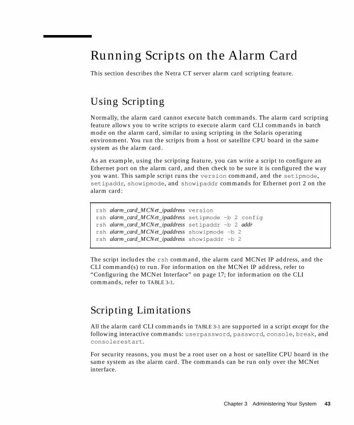
Using ScriptingNormally, the alarm card cannot execute batch commands. The alarm card scriptingfeature allows you to write scripts to execute alarm card CLI commands in batchmode on the alarm card, similar to using scripting in the Solaris operatingenvironment. You run the scripts from a host or satellite CPU board in the samesystem as the alarm card.
As an example, using the scripting feature, you can write a script to configure anEthernet port on the alarm card, and then check to be sure it is configured the wayyou want. This sample script runs the version command, and the setipmode,setipaddr, showipmode, and showipaddr commands for Ethernet port 2 on thealarm card:
The script includes the rsh command, the alarm card MCNet IP address, and theCLI command(s) to run. For information on the MCNet IP address, refer to“Configuring the MCNet Interface” on page 17; for information on the CLIcommands, refer to TABLE 3-1.
Scripting LimitationsAll the alarm card CLI commands in TABLE 3-1 are supported in a script except for thefollowing interactive commands: userpassword, password, console, break, andconsolerestart.
For security reasons, you must be a root user on a host or satellite CPU board in thesame system as the alarm card. The commands can be run only over the MCNetinterface.
rsh alarm_card_MCNet_ipaddress versionrsh alarm_card_MCNet_ipaddress setipmode -b 2 configrsh alarm_card_MCNet_ipaddress setipaddr -b 2 addrrsh alarm_card_MCNet_ipaddress showipmode -b 2rsh alarm_card_MCNet_ipaddress showipaddr -b 2
Chapter 3 Administering Your System 43

▼ To Run a Script on the Alarm Card1. Log in to the server.
2. Create a script:
where alarm_card_MCNet_ipaddress is the MCNet IP address of the alarm card, andCLI_command is the CLI command you want to run.
3. Save the script to a file.
4. As root, run the script:
where path is the path to the script and filename is the name of the script.
Before executing the commands in the script, the alarm card verifies that thecommands are being run by a root user on a host or satellite CPU board in the samesystem as the alarm card, and that the commands have been received over theMCNet.
Administering the CPU BoardsThis section contains information on booting satellite CPU boards.
Booting Satellite CPU BoardsSatellite CPUs can boot from a local disk connected using a PMC SCSI card or overthe network.
By default, the OpenBoot PROM NVRAM boot-device configuration variable isset to disk net, disk being an alias for the path to the local disk, and net being analias for the path of the primary network. You can set the boot device for satellite
rsh alarm_card_MCNet_ipaddress CLI_commandrsh alarm_card_MCNet_ipaddress CLI_commandrsh alarm_card_MCNet_ipaddress CLI_commandrsh alarm_card_MCNet_ipaddress CLI_command...
# /path/filename
44 Netra CT Server System Administration Guide • October 2002

CPUs through the alarm card CLI setfru command. Refer to “Configuring aChassis Slot for a Board” on page 15 for more information on using the setfrucommand to specify a boot device for a board.
When the alarm card powers on a board in a slot, the OpenBoot PROM firmwarechecks with the alarm card for a boot device for that slot; if one exists, the alarm cardsends it to the OpenBoot PROM firmware, which overwrites the NVRAM boot-device variable with the new information.
If you use a DHCP server for downloading software to satellite CPUs, you mustconfigure the DHCP server to add certain information, including the system’smidplane Sun part number (7 bytes), the system’s midplane Sun serial number (6bytes), and the board’s geographical address (slot number) (1 byte). These form the14-byte client ID. Refer to “Displaying Netra CT Server FRU ID Information” onpage 21 for information on using the showfru command to display the Sun partnumber and serial number. For information on how to configure the DHCP server,refer to the Netra HA Suite documentation on reliable DHCP boot.
Using the PMS Application for Recoveryand Control of CPU BoardsThis section describes specifying recovery operations and controlling CPU boardsthrough the alarm card PMS CLI commands.
Recovery Configuration of a CPU Board From theAlarm CardYou specify the recovery configuration of a CPU board by using the command pmsdoperset -s slot_num|all (a single slot number or all slots in the Netra CT systemcontaining a CPU board) and the recovery mode (disabled or enabled) for thespecified slot(s).
The recovery configuration can be maintenance mode (disabled) or operationalmode (enabled). Maintenance mode means the alarm card’s automatic recovery of aCPU board is disabled, and PMS applications are started in an offline state, so thatyou can use manual maintenance operations. Operational mode means the alarmcard’s automatic recovery of a CPU board is enabled; the alarm card will recover theCPU board in the event of a monitoring fault, and start PMS in an active state.
Chapter 3 Administering Your System 45

The mode is stored in persistent storage. You specify the operation to be performedon the specified slot by using the option -o with the parameter maint_config (setthe hardware, operating system, and applications into maintenance mode), oroper_config (set the hardware, operating system, and applications intooperational mode), or graceful_reboot (bring the applications offline if neededand then reboot the operating system).
▼ To Specify the Recovery Configuration of a CPUBoard
1. Log in to the alarm card.
2. Configure the automatic recovery mode with the operset command:
where slot_num can be a slot number from 1 to 8, and all specifies all slotscontaining CPU boards. For example, to make PMS’ recovery operational for theentire Netra CT server, enter:
Printing PMS Recovery Configuration Information
The pmsd infoshow -s slot_num|all command can be used to print the recoveryconfiguration and alarm status for the recovery configuration.
The pmsd historyshow -s slot_num|all command can be used to print a recoveryconfiguration message log. The log is printed to the ChorusOS operatingenvironment.
Detailed Recovery of a Board in Case of FaultYou can perform detailed, manual recovery operations on a board or instruct PMS toperform detailed, automatic recovery operations on a board using the CLI. Theoperations are performed across the hardware, the operating system, and theapplications.
hostname cli> pmsd operset -s slot_num|all -o maint_config|oper_config|gracefulreboot
hostname cli> pmsd operset -s all -o oper_config
46 Netra CT Server System Administration Guide • October 2002

For manual recovery, use the pmsd recoveryoperset -s slot_num|all command.This command can only be run when the board is in maintenance mode (offline). Youspecify the recovery operation to be performed on the specified slot by using theoption -o with the parameters: pc (power cycle), rst (reset), rstpc (reset, thenpower cycle), pd (power down), or rb (reboot).
For automatic recovery, use the recoveryautooperset -s slot_num|allcommand. This command instructs PMS what to do in response to a fault when theboard is in operational mode (active).
You specify the automatic recovery operation to be performed on the specified slotby using the option -o with the parameters: pc (power cycle), rst (reset), rstpc(reset, then power cycle), pd (power down), or rb (reboot). Optional parameters forautomatic recovery include: -d startup_delay (the time in deciseconds between a faultoccurrence and the start of a recovery operation; default is 0 deciseconds), -ffailure power off|on (whether a power down operation will occur if therecovery operation fails; on specifies power down will occur and off specifies thatpower down will not occur; the default is off), -r retries (the number of times arecovery operation can occur and fail before it is terminated; the default is one try),and -p reset power-cycle delay (the time in deciseconds to be waited betweenthe reset and power cycle portions of the recovery operation before a failed reset isdeclared and the power cycle portion of the operation starts; default is 0deciseconds).
▼ To Manually Recover a Board1. Log in to the alarm card.
2. Perform manual recovery operations on a board with the recoveryopersetcommand:
where slot_num can be a slot number from 1 to 8, and all specifies all slotscontaining CPU boards. For example, to instruct PMS to reboot slot 5 after a fault,enter the following:
hostname cli> pmsd recoveryoperset -s slot_num|all -o pc|rst|rstpc|pd|rb
hostname cli> pmsd recoveryoperset -s 5 -o rb
Chapter 3 Administering Your System 47

▼ To Automatically Recover a Board1. Log in to the alarm card.
2. Perform automatic manual recovery operations on a board with therecoveryoperset command:
where slot_num can be a slot number from 1 to 8, and all specifies all slotscontaining CPU boards. For example, to instruct PMS to automatically reboot slot5 after a fault, enter the following:
Printing PMS Automatic Recovery Information
The pmsd recoveryautoinfoshow -s slot_num|all command can be used toprint information showing the configuration information affected by therecoveryautooperset command.
Monitoring and Controlling a CPU Board’sResources From the Alarm CardPMS normally performs operations on a board’s hardware, the operating system,and applications. You can specify that PMS performs one of these, rather than all.
Hardware Operations
The pmsd hwopersest -s slot_num|all command performs operations on thehardware. The operations can only be performed in maintenance mode unless theoptional -f parameter is used. You specify the operation to be performed on thespecified slot by using the option -o with the parameters: powerdown (set thehardware to the power-off state), powerup (set the hardware to the power-on state),reset (reset the hardware), mon_enable (enable health monitoring of thehardware), or mon_disable (disable health monitoring of the hardware). Theoptional -f parameter can be used to perform the operation even if applications arein the active state.
hostname cli> pmsd recoveryautooperset -s slot_num|all -o pc|rst|rstpc|pd|rb [-dstartup_delay][-f failure power on|off][-r retries][-p reset power cycle delay]
hostname cli> pmsd recoveryautooperset -s 5 -o rb
48 Netra CT Server System Administration Guide • October 2002

The pmsd hwinfoshow -s slot_num|all command can be used to print PMSsystem information on the hardware state, monitoring status, and alarm status(whether an alarm was generated).
The pmsd hwhistoryshow -s slot_num|all command can be used to print a shortlog (one-line descriptions) of messages pertaining to changes in the hardware’soperations. The log is printed to the ChorusOS operating environment.
Operating System Operations
The pmsd osopersest -s slot_num|all command performs operations on theoperating system. The operations can only be performed in maintenance modeunless the optional -f parameter is used. You specify the operation to be performedon the specified slot by using the option -o with the parameters: reboot (reboot theoperating system), mon_enable (enable health monitoring of the operating system),or mon_disable (disable health monitoring of the operating system). The optional-f parameter can be used to perform the operation even if applications are in theactive state.
The pmsd osinfoshow -s slot_num|all command can be used to print PMS systeminformation on the operating system state, monitoring status, and alarm status(whether an alarm was generated).
The pmsd oshistoryshow -s slot_num|all command can be used to print a shortlog (one-line descriptions) of messages pertaining to changes in the operatingsystem’s operations. The log is printed to the ChorusOS operating environment.
Application Operations
The pmsd appopersest -s slot_num|all command performs operations on theapplications. You specify the operation to be performed on the specified slot byusing the option -o with the parameters: force_offline (force the applications toan offline state), vote-active (move the group of applications to the active stateonly if all of the applications agree to be moved), or force_active (force theapplications to the active state).
The pmsd appinfoshow -s slot_num|all command can be used to print PMSsystem information on the applications’ state and alarm status (whether an alarmwas generated).
The pmsd apphistoryshow -s slot_num|all command can be used to print a shortlog (one-line descriptions) of messages pertaining to changes in the applications’operations. The log is printed to the ChorusOS operating environment.
Chapter 3 Administering Your System 49

Printing Other PMS Information
The pmsd version command prints the current version of pmsd.
The pmsd usage command prints a synopsis of the pmsd commands.
Using the Netra High Availability SuiteWith the Netra CT Server ApplicationsThe Netra High Availability (HA) Suite software provides enhanced services forcustomer high-availability applications. When installed, it runs on the host andsatellite CPU boards. The Netra HA Suite provides reliable (redundant) servicesacross CPU boards; you can fail over from one CPU board in one Netra CT system toanother CPU board in another Netra CT system.
The MOH and PMS applications integrate with these Netra HA Suite foundationservices: reliable NFS, reliable DHCP/boot server, and CGTP (Carrier-GradeTransport Protocol, providing IP packet services).
The MOH application has to manage these services, for example, monitoring the nfsand tftp daemons. It does this through the node manager agent (NMA). Forexample, if there is an NFS failure, the MOH application will detect this failure.
The points of interaction between the Netra CT server software and the Netra HASuite are:
■ MOH software modules interact with the Netra HA Suite process monitordaemon (PMD) and NMA
■ MOH I/O interfaces interact with the Netra HA Suite NMA and CGTP
■ PMS interacts with the Netra HA Suite probe
▼ To Integrate the Netra High Availability Suiteand the Netra CT Server ApplicationsAfter you have installed the Netra HA Suite, you may want to make the followingcustomization for the Netra CT server:
50 Netra CT Server System Administration Guide • October 2002
1. If you want to change the Netra HA Suite services that are started by default,configure the Process Monitor Daemon (PMD) to start those services.
The Netra HA Suite starts RNFS, RDHCP, and CGTP by default. You may want tostart fewer or more services. Refer to the Netra HA Suite documentation for moreinformation on how to do this.
2. If you want the Netra CT server PMS probe to manage the state of nodes, youmust start that probe instead of the Netra HA Suite probe (started by default). Todo this, replace the Netra HA Suite probe startup script with the Netra CT serverPMS startup script.
The Netra HA Suite probe startup script is installed by default in/etc/opt/SUNWcgha/init.d/nhprobe. The Netra CT server PMS probe startupscript is installed by default in /opt/SUNWnetract/mgmt2.0/bin/ctprobed.
The Netra CT PMS probe brings together the PMS partner list and the Netra HASuite master and vice-master cluster. Refer to the pms API man pages for moreinformation on partner lists; the man pages are installed by default in/opt/SUNWnetract/mgmt2.0/man.
Refer to the Netra HA Suite documentation for more information on this application.
Monitoring Your SystemThis section describes various ways to monitor your system.
Command-line Interface InformationThe alarm card CLI provides many commands to display system status. Refer to thealarm card CLI commands in the section, “Using the Alarm Card Command-LineInterface” on page 33, in particular the show commands, to view system status.
LED InformationThe system status panel is a module designed to give feedback on the status of thekey components within the Netra CT server. The system status panel has one set ofLEDs for each component within that particular server. FIGURE 3-1 shows the LEDson the system status panel for the Netra CT 810 server, and FIGURE 3-2 shows theLEDs on the system status panel for the Netra CT 410 server.
Chapter 3 Administering Your System 51

FIGURE 3-1 System Status Panel (Netra CT 810 Server)
TABLE 3-3 describes the system status panel LEDs for the Netra CT 810 server.
TABLE 3-3 System Status Panel LEDs for the Netra CT 810 Server
LED LEDs Available Component
HDD 0 Power and Okay to Remove Upper hard disk drive
HDD 1 Power and Okay to Remove Lower hard disk drive
Slot 1 Power and Okay to Remove Host CPU board installed in slot 1
Slots 2–7 Power and Okay to Remove I/O boards or satellite CPU boards installed in slots 2–7
Slot 8 Power and Okay to Remove Alarm card installed in slot 8
SCB Power and Fault System controller board (behind the system status panel)
FAN 1 Power and Fault Upper fan tray (behind the system status panel)
FAN 2 Power and Fault Lower fan tray (behind the system status panel)
RMM Power and Okay to Remove Removable media module
PDU 1 Power and Fault (DC only) Left power distribution unit (behind the server)
PDU 2 Power and Fault (DC only) Right power distribution unit (behind the server)
PSU 1 Power and Okay to Remove Left power supply unit
PSU 2 Power and Okay to Remove Right power supply unit
52 Netra CT Server System Administration Guide • October 2002

FIGURE 3-2 System Status Panel (Netra CT 410 Server)
TABLE 3-4 describes the system status panel LEDs for the Netra CT 810 server.
Each major component in the Netra CT 810 server or Netra CT 410 server has a setof LEDs on the system status panel that gives the status on that particularcomponent. Each component has either the green Power and the amber Okay toRemove LEDs (FIGURE 3-3) or the green Power and amber Fault LEDs (FIGURE 3-4).Note that the components in the Netra CT servers all have the green Power LED,and they have either the amber Okay to Remove LED or the amber Fault LED, butnot both.
TABLE 3-4 System Status Panel LEDs for the Netra CT 410 Server
LED LEDs Available Component
Slot 1 Power and Okay to Remove Alarm card installed in slot 1
Slot 2 Power and Okay to Remove I/O board or satellite CPU board installed in slot 2
Slot 3 Power and Okay to Remove Host CPU board installed in slot 3
Slot 4 and 5 Power and Okay to Remove I/O boards or satellite CPU boards installed in slot 4 and 5
HDD 0 Power and Okay to Remove Hard disk drive
SCB Power and Fault System controller board (behind the system status panel)
FAN 1 Power and Fault Upper fan tray (behind the system status panel)
FAN 2 Power and Fault Lower fan tray (behind the system status panel)
FTC Power and Fault Host CPU front transition card or host CPU fronttermination board
PDU 1 Power and Fault (DC only) Power distribution unit (behind the server)
PSU 1 Power and Okay to Remove Power supply
Chapter 3 Administering Your System 53

FIGURE 3-3 Power and Okay to Remove LEDs
FIGURE 3-4 Power and Fault LEDs
■ TABLE 3-5 gives the LED states and meanings for any CompactPCI board installed ina slot in the Netra CT 810 server or Netra CT 410 server.
■ TABLE 3-6 gives the LED states and meanings for any component other than aCompactPCI board that has the green Power and amber Okay to Remove LEDs.
■ TABLE 3-7 gives the LED states and meanings for any component other than aCompactPCI board that has the green Power and amber Fault LEDs.
TABLE 3-5 CompactPCI Board LED States and Meanings
GreenPowerLED state
AmberOkay toRemoveLED state Meaning Action
Off Off The slot is empty or the systemthinks that the slot is emptybecause the system didn’t detectthe board when it was inserted.
If there is a board installed in this slot, then one ofthe following components is faulty:• the board installed in the slot• the alarm card• the system controller boardRemove and replace the failed component to clearthis state.
Blinking Off The board is coming up or goingdown.
Do not remove the board in this state.
On Off The board is up and running. Do not remove the board in this state.
Green Power LED Amber Okay to Remove LED
Green Power LED Amber Fault LED
54 Netra CT Server System Administration Guide • October 2002

Off On The board is powered off. You can remove the board in this state.
Blinking On The board is powered on, but itis offline for some reason (forexample, a fault was detected onthe board).
Wait several seconds to see if the green Power LEDstops blinking. If it does not stop blinking afterseveral seconds, enter cfgadm -al and verify thatthe board is in the unconfigured and disconnectedstate, then perform the necessary action, dependingon the board:• Alarm card—You can remove the alarm card in
this state.• All other boards—Power off the slot through the
alarm card software, then remove the board.
On On The board is powered on and isin use, but a fault has beendetected on the board.
Deactivate the board using one of the followingmethods:• Use the cfgadm -f -c unconfigure
command to deactivate the board. Note that insome cases, this may cause the system to panic,depending on the nature of the board hardwareor software.
• Halt the system and power off the slot throughthe alarm card software, then remove the board.
The green Power LED will then give statusinformation:• If the green Power LED goes off, then you can
remove the board.• If the green Power LED remains on, then you
must halt the system and power off the slotthrough the alarm card software.
TABLE 3-6 Meanings of Power and Okay to Remove LEDs
LED StatePower LED Okay to Remove LED
On, Solid Component is installed andconfigured.
Component is Okay to Remove. Youcan remove the component from thesystem, if necessary.
On, Flashing Component is installed but isunconfigured or is going through theconfiguration process.
Not applicable.
TABLE 3-5 CompactPCI Board LED States and Meanings (Continued)
GreenPowerLED state
AmberOkay toRemoveLED state Meaning Action
Chapter 3 Administering Your System 55

There is also a green system power LED and power on/off button located on thesystem status panel. When the system is off, the system power LED will be unlit.Pressing the system power button when the system is off will start the power-upsequence. Once the system is completely powered up, the system power LEDremains on.
When the system is powered on, pressing the system power button for less than 4seconds will start the orderly power-down sequence—in a manner that no persistentoperating system data structures are corrupted—indicated by a blinking LED. In theorderly power-down, applications in service may be abnormally terminated and nofurther services will be invoked by the CPU. Once the CPU has reached a quiescentstate (run level-0, as if init 0 had been invoked), then the power supply(s) willturn off, indicated by the LED changing from a blinking state to the off state.
If the button is held down for 4 seconds or longer, the power supply(s) are turned offwithout any intervention of the CPU; that is, the “emergency” power-downsequence occurs.
Off Component was not recognized bythe system or is not installed in theslot.
Component is not Okay to Remove.Do not remove the component whilethe system is running.
TABLE 3-7 Meanings of Power and Fault LEDs
LED StatePower LED Fault LED
On, Solid Component is installed andconfigured.
Component has failed. Replace thecomponent.
On, Flashing Component is installed but isunconfigured or is going through theconfiguration process.
Not applicable.
Off Component was not recognized bythe system or is not installed in theslot.
Component is functioning properly.
TABLE 3-6 Meanings of Power and Okay to Remove LEDs (Continued)
LED StatePower LED Okay to Remove LED
56 Netra CT Server System Administration Guide • October 2002

The MOH ApplicationThe MOH collects information about individual field replaceable units (FRUs) inyour system and monitors their operational status. MOH can also monitor certaindaemons; for example, if you installed the Netra High Availability Suite, MOHmonitors daemons through that application.
Starting and Stopping MOHIf you installed the Solaris patches for MOH in a directory other than the defaultdirectory, specify that path instead. You must start the MOH application as root.
Refer to TABLE 2-5 for the options available with cmgtx start.
Once MOH is running, it interfaces with your SNMP or RMI application to discovernetwork elements, monitor the system, and provide status messages. Refer to theNetra CT Server Software Developer’s Guide for information on writing applications tointerface with the MOH application.
Additional Troubleshooting InformationFor additional troubleshooting information, refer to the Netra CT Server ServiceManual.
# cd /opt/SUNWnetract/mgmt2.0/bin/cmgtx# ./cmgtx start [option]
# cd /opt/SUNWnetract/mgmt2.0/bin/cmgtx# ./cmgtx stop
Chapter 3 Administering Your System 57

Hot Swap on the Netra CT ServerMost FRUs in the Netra CT system are hot-swappable.1 Hot swap, a key feature ofthe PICMG standard, means that a CompactPCI board that meets the PICMGstandard can be reliably inserted into or extracted from a powered and operatingCompactPCI platform without affecting the other functions of the platform.
The Netra CT system hot-swap modes are shown in TABLE 3-8.
The Netra CT system is configured for full hot swap by default. You can change themode of the slot for the CPU boards and I/O boards to basic or full hot swap usingthe cfgadm(1M) command. You might want to change the hot-swap state of a slot tobasic, for example, if you need to insert or remove a third-party I/O board that doesnot have full hot-swap support.
Note that whenever you reboot or power your system on and off, the hot-swapstates revert back to the default full hot-swap state for all I/O slots.
Complete information on hot swapping FRUs is contained in the Netra CT ServerService Manual.
1. Exceptions include the single power supply and the single hard disk drive in the Netra CT 410 server; a singleor lone remaining power supply and a single or lone remaining hard disk drive in the Netra CT 810 server;and the power distribution units.
TABLE 3-8 Netra CT System Hot-Swap Modes
Type of Hot Swap Description
Basic The hardware connection/disconnection process is performedautomatically by the hardware, while the software connectionprocess requires user assistance through the cfgadm (1M) command
Full Both the hardware and the software connection process areperformed automatically
High Availability High availability hot swap provides the ability to control thehardware connection process. This provides a higher degree ofcontrol than just indicating insertion and extraction of a board. Thehardware connection process is controlled by software on highavailability systems, such as the Netra CT server
58 Netra CT Server System Administration Guide • October 2002

How High Availability Hot Swap WorksBy default, the Netra CT server is configured to accept any cPCI FRU unless youspecifically set an allowable plug-in for a specific slot. (Refer to “Configuring aChassis Slot for a Board” on page 15 for more information.)
When a board is inserted into the Netra CT server, the alarm card checks themidplane FRU ID information for allowable FRUs for that slot, then checks theinserted board’s FRU ID to make sure the board is allowed in the particular slot. Ifthe board is allowed in the slot, the alarm card powers up the board. If the board isnot allowed in the slot, the alarm card does not enable power to the slot.
If a host or satellite CPU board is in use, that is, has applications currently running,the alarm card CLI power commands, such as poweron or poweroff, will not workfor that CPU board.
Hot Swap With Boards That Don’t Support FullHot SwapYou might want to change the hot-swap state of a slot from full to basic if you needto insert or remove a third-party I/O board that does not have full hot-swapsupport.
To determine the current hot-swap state of a slot, you use the prtconf(1M)command. To enable or disable a type of hot swap on a slot, you use thecfgadm(1M) command. For many cfgadm commands, you must know theattachment point ID for the I/O slot that you will be working on.
Chapter 3 Administering Your System 59

▼ To Determine the Current Hot-Swap State of aSlot
● As root on the server, enter the command:
For a Netra CT 810 server, the output is similar to the following:
■ If you see value ’basic’ underneath the default-hotswap-mode line, thenall of the I/O slots in the Netra CT server have been set to basic hot swap. Youshould see value ’disabled’ for every I/O slot in the system in this situation.
■ If you see value ’full’ underneath the default-hotswap-mode line, then atleast one of the I/O slots in the Netra CT server has been set to full hot swap. Youmust look at the entries for individual I/O slots to determine if they have been setto basic or full hot swap mode in this situation:
# prtconf -v -P
cphsc, instance #0 System properties: name=’instance’ type=int items=1 value=00000000 name=’default-hotswap-mode’ type=string items=1 value=’full’ Driver properties:
name=’AL-8-autoconfig’ type=string items=1 dev=none value=’enabled’
name=’IO-7-autoconfig’ type=string items=1 dev=none value=’enabled’
name=’IO-6-autoconfig’ type=string items=1 dev=none value=’enabled’
name=’IO-5-autoconfig’ type=string items=1 dev=none value=’enabled’
name=’IO-4-autoconfig’ type=string items=1 dev=none value=’enabled’
name=’IO-3-autoconfig’ type=string items=1 dev=none value=’enabled’
name=’IO-2-autoconfig’ type=string items=1 dev=none value=’enabled’
name=’CPU-autoconfig’ type=string items=1 dev=none value=’enabled’ name=’hotswap-mode’ type=string items=1 dev=none value=’full’
60 Netra CT Server System Administration Guide • October 2002

■ If you see value ’enabled’ underneath an autoconfig line, then that slotis set to full hot swap.
■ If you see value ’disabled’ underneath an autoconfig line, then that slotis set to basic hot swap.
▼ To List Attachment Point IDs for I/O Slots● As root on the server, enter the command:
For a Netra CT 810 server, the output is similar to the following:
where the attachment point ID is shown in the first column of the readout; forexample, the attachment point ID for I/O slot 2 in a Netra CT 810 server would beIO-2.
For a Netra CT 410 server, the output is similar to the following:
where the attachment point ID is shown in the first column of the readout; forexample, the attachment point ID for I/O slot 4 in a Netra CT 410 server would beIO-4.
# cfgadm
Ap_Id Type Receptacle Occupant ConditionAL-8 mcd/fhs connected configured okCPU bridge/fhs connected configured okIO-2 stpcipci/fhs connected configured okIO-3 unknown empty unconfigured unknownIO-4 stpcipci/fhs connected configured okIO-5 unknown empty unconfigured unknownIO-6 unknown empty unconfigured unknownIO-7 unknown empty unconfigured unknown
Ap_Id Type Receptacle Occupant ConditionAL-1 mcd/fhs connected configured okCPU bridge/fhs connected configured okIO-2 unknown empty unconfigured unknownIO-4 stpcipci/fhs connected configured okIO-5 stpcipci/fhs connected configured ok
Chapter 3 Administering Your System 61

▼ To Disable Full Hot Swap and Enable Basic HotSwap
● As root on the server, enter the command:
where ap_id is the attachment point ID in the server that you want to have basic hotswap enabled on.
▼ To Re-Enable Full Hot Swap● As root on the server, enter the command:
where ap_id is the attachment point ID in the server that you want to have full hotswap enabled on.
# cfgadm -x disable_autoconfig ap_id
# cfgadm -x enable_autoconfig ap_id
62 Netra CT Server System Administration Guide • October 2002

Index
AACL file, 26alarm card
accessing, 6and PMS application, 29 to 32, 45 to 50command-line interface, 1, 3, 33 to 39console, 6, 35, 39date and time, 42description of, 2, 3Ethernet ports, 8flashing, 40permission levels, 34scripts, 43 to 44serial ports, 6user account, 6, 9 to 11
BBCF firmware, 2, 3, 40BMC firmware, 2, 3, 40boot device, 13, 36, 44
Ccfgadm command, 59ChorusOS operating environment, 1, 3, 40cluster, 51command-line interface, 1, 3, 33 to 39console, 6, 35, 39cPCI bus, 2, 3
CPU board, 2, 3, 12, 14, 15, 25, 27, 30, 44, 45, 58, 59
Ddate and time, 42DHCP, 45, 50documentation, xiii
EEthernet ports, 8, 17
Ffailover, Ethernet ports, 8flash, alarm card, 36, 40FRU ID, 11 to 24, 59FRU, system, 11
Hhost CPU board, 2, 3, 12, 14, 15, 25, 27, 30, 44, 45, 58,
59hot swap, 58 to 62
II/O board, 3, 12, 14, 15, 58, 59
63

IPMI, 2, 3
JJDMK, 26
LLEDs, 51 to 56
MManaged Object Hierarchy application, see MOH
applicationMCNet, 2, 3, 17 to 20, 43MOH application, 2, 3, 25 to 29
NNetra High Availability Suite, 2, 50 to 51NFS, 50NTP, 42
OOpenBoot PROM firmware, 2, 3, 13, 15, 25, 44
Ppanic dump, 35partner list, 29, 51password, 6, 10patches, Solaris, 25permission levels, alarm card, 34PMC card, 44PMS application, 2, 3, 29 to 31, 45 to 50POST, 2power on/off server, 13, 21Processor Management Service application, see
PMS applicationprtconf command, 59
Rrecovery, CPU boards, 45 to 48RMI, 29
Ssatellite CPU board, 2, 3, 12, 14, 15, 25, 27, 30, 44, 45,
58, 59scripts, alarm card, 43 to 44security, 39, 43serial ports, 6slot, 12, 15 to 17, 59 to 62SMC firmware, 2, 3SNMP, 26, 29Solaris operating environment, 1, 3, 25system status panel, 51
Ttelnet, 6tip program, 6
Uuser account, 3, 6, 9
Vvariables, system configuration, 33, 40
64 Netra CT Server System Administration Guide • October 2002