netra--a parallel architecture for integrated vision ... · architecture for integrated vision...
TRANSCRIPT

De ember 1989--_ =_
UILU-ENG-89-224i-
CSG-117
COORDINATED SCIENCE LABORATORY_ - College of Engineering
, i .... ±E___ : ;T
:. ==,,
Z- t,u,,
S.
NETRA--A PARALLELARCHITECTUREFOR INTEGRATEDVISION SYSTEMS
_! ARCHITECTUREAND ORGANIZATION
7 ZZ
Alok N. ChoudharyJanak H. Patel
Narendra Ahuja
(NASA-CR-185955) NFTRA: A PARALLEL
ARC_ITECT!JRF FUR INTEGRAT_O VISION SYSTFMS.
1: ARCHITFCTURE AND ORGANIZATION (Illinois
UniV.) 40 p CSCL OqB
N90-14S39
Uncl._s
G3/03 0254490
UNIVERSITY OF ILLINOIS AT URBANA-CHAMPAIGN
Approved for Public Release. Distribution Unlimited.
https://ntrs.nasa.gov/search.jsp?R=19900005523 2018-07-17T05:45:46+00:00Z

im
iB
7-- N
ID
-:7
W
_t
hJ
i
W
_ _r ¸,- =_7: =

SECuRItY CLASSJF;CATION OF TMIS PAGEm ii i i
la. REPORT SECURITY CL_SStFICATION
Unclassified
2a. SECURITY CLASSIFICATION IAUTHORITY
2b. DECLAS$1FIO_TIONIOOWNGRADING SCHEDULE
REPORT DOCUMENTATION PAGE
|| C ml i' lb. RESTR! TWE MARKINGS
,, None •3 • DISTRIBUTION IAVAJLABIUTY OF RE_ORT
Approved for public release;
distribution unlimited
4. PERFORMING ORGANIZATION REPORT NUMBER(S)
UILU-ENG-8}-2241 (CSG-II7)
6,1. NAME' OF PERFORMING ORGANIZATION
Coordinated Science Lab
University of Illinois
6c. ADDRESS (Dry, State, and ZIP Code)
Ii01 Wm Springfield Avenue
Urbana, IL 61801
8a. N,_ME OF FUNDINGISPONSORINGORGANIZATION
NASA
8c ADDRESS (City, State, and ZIP Code)'
see 7b
6b. OFFICE SYMBOL
(/f _pp//cable)
N/A
8b. OFFICE SYMBOL(If applicable)
mm
i
Architecture for Integrated
11. TITLE (Include Securi_/ Cl_¢dfication)NETRA - A Parallel
Organization
12. PERSONAL AUTHOR(S)"I
Choudhary, A. N.,
13a. TYPE OF REPORT
Technical
16. SUPPLEMENTARY NOTATION
S. MONITORING ORGANIZATION REPORT NUMBER(S)
7a. NAME OF MONITORING ORGANIZATION
NASA
7b. ADDRESS (O1_, Stat_, 0t_ ZIP _ode;
NASA Langley Research Center
Hampton, VA 23665
9. PROCUREMENT INSTRUMEN'_ IDENTIFICATION NUMBER
NASA NAG 1-613
10. SOURCE OF FUNDING NUMBERS
ELEMENT NO. .WORK UNITACCESSION NO,
Vision Systems I: Architecture and
Patel, J. H. and Ahuja, N.i
I FROM ,TO i_8_ December 7 _7r
17. COSATI CODES 18. SUBJECT TERMS (Corrdnue on reverse if Recessaty and/dentify by b/ock numbed
FIELD GROUP SUB-GROUP muI t i p roces so r arch i tectu re, pa ral J el p rotes s[ng, v J s [on,
image processing, parallel algorithms, performanceevaluat ion
!9. ABSTRACT (Continue on reverse if necessary and/dent_'fy by b/eeL number)
Computer vision has been regarded as one of the most complex and compuiatJonally inlcnsive problems. Anintegrated vision system (IVS) is considered to b¢ a system that uses vision algorithms from all levels of processingfor a high level application (such as object recognition). This paper presents a model of computation for parallelprocessing for an IVS. Using the model desired features and capabilities of a parallel architecture suitable for IVSs
arc derived. Then a multiprocessor archimctur¢ (called NETRA) is presented. Originally NETRA was proposed inI. NETRA is highly flexible without the use of complex intcrconnccdon schemes. The topology of NETRA isrecursivcly defined, and hence, is easily scalable from small to large systems. Homogeneity of NETRA permits faulttolerance and graceful degradation under faults. NETRA is a rccursively defined u'ce-type hierarchical architecture
each of whose leaf nodes consists of a cluster of processors connecmd with a programmable crossbar with selective
broadcast capability to provide for desired flexibility. A qualitative evaluation of NETRA is presented. Then gen-eral schemes are described to map parallel algorithms onto NETRA. Algorithms are classified according to their
communication requirements for parallel processing. An extensive analysis of inter-cluster communication stra-
tegies in NETRA is presented, and parameters affecting performance of parallel algorithms when mapped onNETRA are discussed, Finally, a methodology to evaluate performance of algorithms on NETRA is described.
20. DISTRIBUTION/AVAILABILITY OF ABSTRACT 121.ABSTRACT SECURITY CLASSIFICATION
[] UNCLASSIFIED/UNLIMITED I"1 SAME AS RPT. I"1 DTIC USERS J Unclassified
22a. NAME OF RESPONSIBLE iNDIVIDUAL ' I22b.TELEPHONEOncIudeAre.Code) J22c. OFFiCE SYMBOL
! ....II III
DO FORM 1473, 84 MAR 83 APR edition may be used until exhausted. SECURITY CLASSIFICATION .QF THIS PAGEAll other editions are obsolete.
I_;CLASSIFIED
UN_SIFIED
,_cu_aTv¢L_t_lca_o. op v.,. pA_
Part II of this paper 2 presents performance evaluation of computer vision algorithms on NETRA. Perfor-mance of algorithms when they arc mapped on a cluster is described. For some algorithms, performance resultsbased on analysis are compared with those observed in an implementation. It is observed that the analysis is veryaccurate. Performance analysis of parallel algorithms when mapped across clusters is presented. Alternative com-munication communication strategies in NETRA arc evaluated. The effect of the requirement of interprocessorcommunication on the execution of an algorithm is studied. It is observed that if communication speeds arematched with the computation speeds, almost linear speedups are possible when algorithms are mapped across clus-ters.
UNC_ASSIFIED_tcum'rv Ct.ASSIFICA'nO. 0_" vms ps_1:
1

w
J
NETRA - A Parallel Architecture for Integrated Vision Systems hArchitecture and Organization
Aiok N. Choudhary, Janak H. Patel and Narendra Ahuja
Coordinated Science LaboratoryUniversity of Illinois1101 W. SpringfieldUrbana, IL 61801
Index Terms - Multlproc_ Architecture, Parallel Processing, Vision, Image Processing, Parallel Algorithms,Performance Evaluation
Corresponding Author : Prof. Alok N. Choudhary
Electrical and Computer Engineering DepartmentScience and Technology Center
Syracuse University,Syracuse,NY 13244
w
w
r
w

I
O
i
RIP
Ill
l!
ibm
iMP
in
air
_If !
.
= ,
w
w
NETRA - A Parallel Architecture for Integrated Vision Systems I:
Architecture and Organization
Alok N. Choudhary, Janak H. Patel and Narendra Ahuja
Coordinated Science LaboratoryUniversity of Illinois1101 W. SpringfieldUrbana, IL 61801
Abstract
W
w
Computer vision has been regarded as one of the most complex and computationally intensive problems. Anintegrated vision system CIVS) is considered to be a system that uses vision algorithms from all levels of processingfor a high level application (such as object recognition). This paper presents a model of computation for parallelprocessing for an IVS. Using the model desired features and capabilities of a parallel architecture suitable for IVSsare derived. Then a multiprocessor architecture (called NETRA) is presented. Originally NETRA was proposed in1. NETRA is highly flexible without the use of complex interconnection schemes. The topology of NETRA isrecursively defined, and hence, is easily scalable from small to large systems. Homogeneity of NETRA permits faulttolerance and graceful degradation under faults. NETRA is a recursively defined tree-type hierarchical architectureeach of whose leaf nodes consists of a cluster of processors connected with a programmable crossbar with selectivebroadcast capability to provide for desired flexibility. A qualitative evaluation of NETRA is presented. Then gen-eral schemes are described to map parallel algorithms onto NETRA. Algorithms are classified according to theircommunication requirements for parallel processing. An extensive analysis of inter-cluster communication stra-tegies in NETRA is presented, and parameters affecting performance of parallel algorithms when mapped onNETRA are discussed. Finally, a methodology to evaluate performance of algorithms on NETRA is described.
Part II of this paper 2 presents performance evaluation of computer vision algorithms on NETRA. Perfor-mance of algorithms when they are mapped on a cluster is described. For some algorithms, performance resultsbased on analysis are compared with those observed in an implementation. It is observed that the analysis is veryaccurate. Performance analysis of parallel algorithms when mapped across clusters is presented. Alternative com-munication communication strategies in NE'IRA are evaluated. The effect of the requirement of interprocessorcommunication on the execution of an algorithm is studied. It is observed that if communication speeds arematched with the computation speeds, almost linear speedups are possible when algorithms are mapped across clus-ters.
r
v
w
This researchwas supportedin part by NationalAeronautics and SpaceAdministration UnderContract NASA NAG-l-613.
W
m
i
mm
w
im
i
Wl •
m
IE
I!
mm
IB
m _
u _
m _

s
v
w
m
m
E
v
Table of Contents
1. Introduction ....................................................................................................................................................
2. Model of Computation for Integrated Vision Systems ..................................................................................
2.1. Data Dependencies .............................................................................................................................. ,'"
2.2. Features and Capabifities of Parallel Architectures for IVS ..................................................................
3. Architecture ............................................................................................................. _.....................................
3.1. Processor Clusters ...................................................................................................................................
3.1.1. Crossbar Design ...............................................................................................................................
3.1.2. Scalability of Crossbar .....................................................................................................................
3.2. The DSP Hierarchy .................................................................................................................................
3.3. Global Memory .......................................................................................................................................3.4. Global Interconnection ...........................................................................................................................
3.5. IVS Computation Requirements and NETRA ........................................................................................
4. Mapping Parallel Algorithms ........................................................................................................................
4.2. Mapping an Algorithm on One Ouster ..................................................................................................
4.3. Mapping an Algorithm on More than one Cluster .................................................................................
5. Inter-cluster Communication in NETRA ......................................................................................................
5.1. Analysis of Inter-Ouster Communication ..............................................................................................
5.2. Approach to Performance Evaluation of Algorithms ............................................................................
6. Summary ........................................................................................................................................................
1
3
4
7
8
8
11
11
12
13
14
15
19
21
22
25
27
31
32
w

mm
up
im
m
m
m
m
i
w
W
II
m
g
mmt
g ,
m
lid
mBBm
m
m
Iw

L
- °
= =
r
w
L ,
w
ij
F_
w
1. Introduction
Computer vision has been regarded as one of the most complex and computationally intensive problems. The
algorithms involved employ a very broad spectrum of techniques from several areas such as signal processing,
advanced mathematics, graph theot'y, and artificial intelligence. These algorithms are, in general, characterized by
massive parallelism. For low level processing, spatial decomposition of image provides a naturedway of generating
parallel tasks. For higher level processing operations, parallelizatlon may also be based on other image characteris-
tics. The multi-dimensional divide-and-conquer paradigm [3] is an attractive mechanism for providing parallelism
in both of the above cases.
There is no general definition of an Integrated Vision System OVS). However, an application dependent
definition of an IVS is possible. For example, an object recognition, system that takes an image (or a set of images)
of an object as input and produces as an output a description of the object can be considered an IVS. However, a
system (or an algorithm) that takes an image input and produces its Discrete Fourier Transform (DFT) is not con-
sidered an IVS though computing DFT itself may be a part of an IVS. Therefore, IVS can be viewed as a system
which employs a number of vision algorithms in a systematic way to produce a specified output. In this paper we are
interested in an IVS from the viewpoint of complexity and execution of the necessary computations. An architec-
ture for vision must be powerful as well as general enough to efficiently execute algorithms for any given computer
vision problem. Researchers in vision and architecture communities are recognizing the need for architectures that
are suited for IVSs rather than those architectures that are good for a few applications but are too rigid to perform
any other applications efficiently. In [4] Weems et al. present an integrated image understanding benchmark that
consists of algorithms that may comprise an object recognition system.
The advent of VLSI technology has provided architects to produce high performance chips for specific appli-
cations. But these special purpose chips can only be used in an IVS as accelerators of specific algorithms (e.g., con-
volution chips or FFT chips). Another use of VLSI technology has been to create massively parallel Single Instruc-
tion Multiple Data (SIMD) processors for vision and other applications. Massively parallel SIMD processors are
well suited for low level and well structured vision algorithm that exhibit spatial parallelism at pixel level. However,
such architectures are not well suited for for high level vision algorithm because high level vision algorithms require
non-uniform processing, more complex data structures and data dependent decision making capabilities. Further-
more, mapping a parallel algorithm on such architectures becomes really inefficient when the problem size does not
w

match with the available processor size and when its communication requirements do not match with the underlying
interconnecfion structure of the parallel processor machine..
Meshes, array processors, hypercubes and pyramids are some of the most common SIMD parallel processors
proposed for image analysis and processing. In meshes, the processing elements are arranged in a square array.
Examples of mesh connected computers include CLIP4 [5,6,7], and the MPP [8,9,10]. In [11], Ahuja and Swamy
proposed multiprocessor pyramid architecture of the divide-and-conquer based approach model of computation.
Such pyramids arc, therefore, natural candidates for executing divide-and-conqner algorithms that closely mirror the
flow of information in these algorithms. Example of other pyramid architectures include PAPIA [12], SPHINX [13],
MPP pyramid [14], and HCL Pyramid [15,16]. However, design of an integrated vision system requires a greater
flexibility, partiLionability, and rcconfigurability than is offered by regular array, mesh connected or pyramid struc-
tures as discussed in [1]. For this reason other mulfipmcessor architectures and pfa-allel algorithms have been pro-
posed [17, 18, 19,20], some of which discuss the flexibility, partitionability, and reconfigurability issues. CMU
Warp process_ [21,22,23,24] is another machine proposed and built for image understanding. The machine has a
programmable systolic array of linearly connected cells. The array can perform low level and high level vision
algorithms in systolic mode for low level operations and in MIMD mode for high level operations. There axe unique
features in the Warp processor that are not present in other architectures. The machine can be reconfigured in
several modes [25]. The UMass image understanding architecture is based on Content Addressable Array Parallel
Processor for low level vision and a MIMD parallel processor for high level vision [26].
The effectiveness and performance of architectures such as pyramid, array processors, and meshes is limited
as architectures for integrated vision systems due to several reasons. First, they are mostly suitable for SIMD type
of algorithms which only constitute low level vision operations, Secondly, the architectures are inflexible due to the
rigid interconnections. Third, the number of processors needed to solve a problem of reasonable size is thousands.
Such a large number of processors is not only cost prohibitive, but the processors themselves cannot be very power-
ful and can have only limited features due to technological limitations. Fourth, it is normally assumed that the prob-
lem size exactly matches the number of processors available. Most of the time it is not clear how to adapt algo-
rithms so that problems of differerg _ _ be solved using the me number of p_rocessors. Finally, the problem
of input-output of data and fault-tolerance is rarely addressed in any of these architectures. It is important to note
that no matter how fast or powerful a particular architecture is, its utilization can be limited by the bandwidth of the
I
m
gg
B
i
I
Ig
I
I
Ill

= ,
=
3
I/O. Ftmhermore, a failure normally either results in a breakdown of the entire system or the performance degrades
tremendously. It is important thatthe architecture provide for graceful degradation. Graceful degradation can be
achieved by providing flexibility in the interconnection and a capability for dynamic reconfiguration and partitioning
of the architectare.
In this paper, we present a parallel architecture called NETRA for IVSs which is intended to provide the
above flexibility. The architecture was originally proposed by Sharma, Patel and Ahuja [1]. NETRA is a recur-
sively defined tree-type hierarchical architecture each of whose leaf nodes consists of a cluster of processors con-
nected with a programmable crossbar with selective broadcast capability. The internal nodes are scheduling proces-
sors whose function is task scheduling, load balancing, and global memory managemenL All the scheduling proces-
sors and the cluster processors are connected to a global memory through a multistage circuit switched network.
The processors in clusters can operate in SIMD, MIMD or systolic mode, and therefore, are suitable for both low
level as well as high level vision algorithms.
In Section 2 we propose a model of computation for integrated vision systems. The model is discussed from
the parallel processing perspective. Using the model we derive desired features and capabilities of a parallel archi-
tectm'e for IVSs. Section 3 presents the. architecture of NETRA and describes its components and their functions in
detail. Then the architecture is critically examined with respect to the IVS requirements. In Section 4 we present
methods to map parallel algorithms on NETRA. We also discuss the alternative communication strategies in
NETRA and present a qualitative evaluation of the strategies. The algorithms are classified according to their com-
putation and communication requirements for parallel processing. Section 5 presents analysis of alternative inter-
cluster communication strategies in NETRA and discusses a methodology to evaluate a parallel algorithm which has
been mapped across clusters. Finally, a summary is presented in Section 6.
2. Model of Computation for Integrated Vision Systems
There are two types of parallelism available in vision tasks. First, Sp_ria/ParaUelism, in which the same
operation is applied to all parts of the image data. That is, the data is divided into many granules and distributed to
different subtasks which may execute on different processors in parallel. Most low level vision algorithms exhibit
this type of parallelism. However, different tasks may be performed sequentially in time on the same granules of
data. Each such _ operates on the output data of the previous task. Therefore, the type of data, data structures, etc.,

maybedifferentforeachtaskin thesystem but each form of dam can be partitioned into several granules, to be pro-
cessed in parallel. For example, consider one IVS that performs object recognition. The input image is smoothed
using some filtering operation, then on the smoothed image an operator is applied for feature extraction, features
with similar characteristics are grouped, then matching with the models is pedorme_ Each of these tasks takes the
output of the previous tasks as its input and produces an output which becomes the input for the next task.
Second form of parallelism called Temporal Parallelism is available when these tasks ate repeated on a time
sequence of images or on different resolutions of images. For example, the system in which the motion of a moving
object is estimated from an image sequence performs the same set of computation on all image frame(s) in the
sequence. The processing of each frame or sets of frames can be done in parallel.
Figure 1 shows a computational model of IVS which incorporates the above mentioned characteristics. Each
pipeline shows a number of tasks applied to a set of inputs. Each block in the pipeline represents one task. The
input to the first task in a pipeline is the image, and the input to the rest of the tasks is the output of the previous task.
Entire pipeline of tasks is repeated at different images in time and/or resolution. Each task is decomposed into sub-
tasks to be performed in parallel. For example, T 1 is one task, and T 1(d 1) is a subtask of T 1 operating on data
granule d 1. The figure shows m tasks in the pipeline. The number of subtasks depends on the amount of data in a
granuleand numberofavailableprocessors.Di,i+1 representsdatatransferfromtaskTitotaskTi+1 inthepipe-
line.
2.1. Data Dependencies
Existence of spatial and temporal parallelism may also result in two types of data dependencies, namely, spa-
tial data dependency and temporal data dependency. The spatial data dependency can be classified into inwatask
data dependency and intertask data dependency. Intratask clam dependency arises when a set of subtasks need to
exchange data in order to execute a task in parallel. The exchange of dam may be needed during the execution of the
algorithm, or to combine their partial results, or both. Therefore, each task itself is a collection of subtasks which
may be represented as a graph with nodes representing the subtasks and edges representing communication between
submsks. Intertask data dependency denotes the transfer and reorganization of data to be passed onto the next task in
the pipeline. This may be done by exchanging data between submsks of the current tasks and the subtasks of the
next task, or by collection and reorganization of the output data of current task and then redistribution of the data.
a
Q
k_
g
U
W
g
mg
wI
lu
=..__
u
g
D
m
u
W

-= T
m
w
ii#
w
W
Input
/i
DI
InputImage
Frames
Inpm
D'I
Input
1i+2
D" 1
Data Dependencies (Spatial)
Tt(dl)
T 1(d2)
Tl(dnl)
DL2
Tt(dt)
Tt (d2)
T1(dnl)
D'l,2
T2(dl)
T2(d2)
T2(dn2)
T1(dl)
T I(d2)
Tl(dnl)
Data Dependencies
Data_De__pendencies (Spatial)
Tin(d1)
Tin(d2)
Tm(d.r,t)
D"l,2
(Temporal)
T2(dl)
= T2(d2) __D'z3• 000
T2(dn2)
Data Dependencies 1
T2(dt)
T2(d2)
• 000
T2(dn2)
Output
Tm(dl)
Tin(d2)
@
Tm(d,,m)
("Temporal)
Output
Tm(dl)
Tin(d2)Output
Tm(dnm)
Figure 1 : A Computational Model of an Integrated Vision System
The choice and method depends on the underlying parallel architecture and mapping of the algorithms. Temporal
data dependency is similar to spatial data dependency except that some form of output generated by tasks executed
on the previous image frames may be headed by one or more tasks executing on the current image frames. A simple
example of such a dependency is the system for modon estimation in which features from the previous image
frames are needed in the processing of the current image frames so that features can be matched to establish
correspondences between features ofdifferent time frames.
6
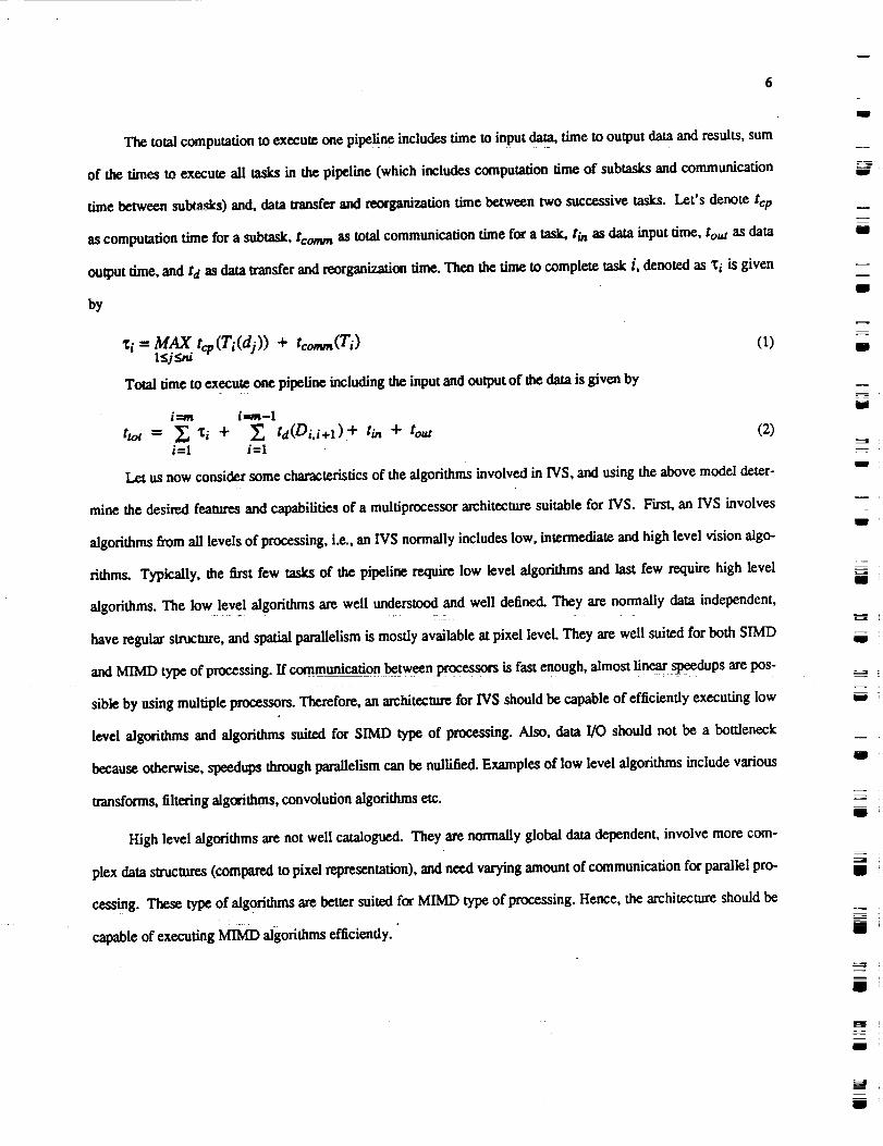
The total computation to execute one pipeline includes time to input dam, time to output data and results, sum
of the times to execute all tasks in the pipeline (which includes computation time of subtasks and communication
time between [email protected]) and, data transfer and reorganization time between two successive tasks. Let's denote tcp
as computation time for a subtask, tcomm as total communication time for a task, t/n as data input time, tou t as data
output time, and td as data transfer and reorganization time. Then the time to complete task i, denoted as Xi is given
by
= MAX tq,(T (dj))+ (o1<j _,d
Total time to execute one pipefine including the input and output of the data is given by
t._,,n i---m-1
trot = _ '_i + _'. fd(Di, i+l) + tin + tout (2)i=l i=1
Let us now consider some characteristics of the algorithms involved in INS, and using the above model deter-
mine the desired features and capabilities of a multiprocessor architecture suitable for INS. First, an IVS involves
algorithms from all levels of processing, i.e., an INS normally includes low, intermediate and high level vision algo-
rithms. Typically, the first few tasks of the pipeline require low level algorithms and last few require high level
algorithms, The low level algorithms are well understood and well defined. They are normally data independent,
have regular structure, and spatial parallelism is mostly available at pixel level. They are well suited for both $IMD
and MIMD type of processing. If communication between processors is fast enough, almost linear speedups are pos-
sible by using multiple processors. Therefore, an architecture for INS should be capable of efficiently executing low
level algorithms and algorithms suited for SIMD type of processing. Also, data I/O should not be a bottleneck
because otherwise, spccdups through parallelism can be nullified. Examples of low level algorithms include various
transforms, filtering algorithms, convolution algorithms etc.
High level algorithms are not well catalogued. They are normally global data dependent, involve more com-
plex data structures (compared to pixel representation), and need varying amount of communication for parallel pro-
cessing. These type of algorithms are better suited for MIMD type of processing. Hence, the architecture should be
capable of executing MTMD algorithms efficiently.
u
I
W
u
J
g
J
g
.===.
w
I
t
m
m
I
I
D

laid
2.2. Desired Features and Capabilities of Parallel Architectures for IVS
(1) Reconfigurability :From the model and the above discussion it is clear that the architecture should be capable
of executing both SIMD and IMD type of algorithms efficiently. That is, it should be possible to
reconfigure the architecture such that each algorithm can be implemented efficiently using the most suited
mode of computation.
(2) Flexible Communication : The communication requirements vary for different algorithms. The communica-
tion pattern between tx'ocessors executing subtasks of a larger task depends on the algorithm involved in the
task. If the connectivity between processors is too rigid then the communication overhead of intratask and
intertask commtmieation may become prohibitive. Therefore, it is desirable that the communication be flexi-
ble in order to provide most efficient communication with low overhead.
(3) Resource Allocation and Partitionability : As we discussed earlier, there are several tasks with vastly different
characteristics and computational requirements in an IVS. These tasks need to exist simultaneously in the sys-
tem. Therefore, the system should be pastitionable into many independently controlled subsystems to execute
each task. Since the high level algorithms exhibit varying level of parallelism and data dependent perfor-
mane.e, it should be possible to allocate resources (such as processors, memory) dynamically to meet the per-
formance requirements.
(4) Load Balancing and Task Scheduling : Load balancing and task scheduling are very important, specially for
high level vision algorithms. High level vision algorithms are data dependent, and therefore, in order to obtain
better utilization of resources and better speedups, dividing the computation equally among the processor is
critical [27]. The underlying architecture on which load balancing is done and the type of algorithm(s)
involved contribute significantly to how well load balancing can be achieved. In low level algorithms since
the computations are data independent, partitioning data equally among the processors normally balances the
load among the processors. However, for high level algorithms more sophisticated load balancing and
scheduling strategies are needed. The architecture should include features such that it is easy to perform load
balancing and task scheduling and that the overhead of doing so is minimal.
(5) Topology and Data Size Independent Mapping : For a system as complex as an IVS, if the underlying archi-
tecture is rigid such that the problem size that can be solved on it dependent on the size of the architecture,
the effectiveness of the architecture for an IVS will diminish.

(6) Input-Output of Data : It is most often the case that an architecture is able to perform very well on some algo-
rithms and high speedups are obtained but input-output (I/O) of data is inefficient. I/O is an integral part of a
system and if it is a bottleneck then performance of the system will be limited.
(7) Fault-Tolerance : Fault-tolerance is an important part of a system of such complexity. A failure in a processor
or communication structure should not affect the performance drastically which is normally the case when
rigid interconnectious are present between processors. The architecture should provide for graceful degrada-
tion in case of failures.
3. Architecture o(NETRA
In this section we describe the architecture of NETRA and its features. We examine and evaluate the charac-
terisfics of the architecture using the criteria developed in the previous section.
Figure 2 shows the architecture of "NETRA" for integrated vision systems. The architecture consists of the
following components :-
(1) A large number (10(X) - 10000) of Processing Elements (PEs), organized into clusters of 16 to 64 PEs each.
(2) A tree of Distributing-and-Scheduling-Processors (DSPs) that make up the task distribution and control struc-
ture of the multiprocessor.
O) A parallel pipefined shared Global Memory and a Global lnterconnection that links the PEs and DSPs to the
Global Memory.
3.1. Processor Clusters
The clusters consist of, 16 t064 PEs, each with its own pro_,and data memory. They form a layer below
the DSP-tree, with a leaf DSP associated with each cluster. PEs within a cluster also share a common data memory.
The PEs, the DSP associated with the cluster, and the shared memory are connected together with a crossbar switch.
The crossbar switch permits point-to-point communications as well as selective broadcast by the DSP or any of the
PEs. Figure 3 shows the cluster organization. A 4x4 crossbar is shown as an example of the implementation of the
cmssbur switch. The crossbar design consists of pass transistors connecting the input and output data lines. The
switches are controlled by control bits indicating the connection pattern. If a processor of DSP needs to broadcast
then all the control bits in its row ate made one. In order to connect processor Pi to processor P j, control bit (i,j) is
g
m
i
I
m
m
m
I
m
Ill
mW
g
I
I
m
m
m
m
I
m
m

w
J
--=
/
D ;!
/\
Ii
./I
I
/,
C C
DI
I
),_,F
C C
• " I |
ii II
1
),u
I
//
I DS_
/ .
C t2
_Fw
I
/
C
DSI
A\
\
C
W
GLOBAL INTERCONNECTION
I I I I
SECONDARY STORAGE AND I/O DEVICES
lira DSP : Distributing and Scheduling Processor
C : Processor Ouster M : Memory Module
Figure 2 : Organization of NETRA
set to one and rest of the con_ol bits in row i and column j are off.
Clusters can operate in an SIMD mode, a systolic mode, or an MIMD mode. Each PE is a general purpose
processor with a high speed floating point capability. In an SIMD mode, PEs in a cluster execute identical instruc-
tion sa_ams from private memories in a lock-step fashion. In the systolic mode, PEs repetitively execute an insmic-
tion or set of instruction on data streams from one of more PEs. In both cases, communication between PEs is syn-
chronous. In the MIMD mode PEs asynchronously execute instruction streams resident in their private memories.
W

W
10
lid
o LOBAL
TO
GLOBALMEMOR_
fS_CHRONIZATION BUS
Control Bit
Example 4x4 Crossbar
UNIDIRECTIONAL
CROSSBAR
PE" PROCESSOR M'LOCALMEMORY
CDM" COMMON DATA MEMORY
Fibre 3: OrganizationofProcessorCluster
The streams may not be identical. In order to synchronize the processors in a cluster, a synchronization bus is pro-
vided which is used by processors to indicate to the DSP that a processor(s) has finished its computation or a proces-
sor wantsto change the communication pattern. The DSP can either poll the processors or the processors can inter-
rapttheDSP usingthesynchronizationbus.
g
i
m[g
i
i
i
J
i
_=_=W
i
m
m
I
i
m
i
g
i
U

u
W
W
W
L_
w
i
I1
3.1.1. Crossbar Design
There is no arbitration in the crossbar switch. That is, the interconnection between processor has to be pro-
grammed before processors can communicate with each other. Programming a crossbar requires writting a com-
munication pattern into the control memory of the crossbar. A processor can alter the communication pattern by
updating the control memory as long as it does not conflict with the existing communication pattern. The DSP asso-
ciated with the cluster can write into the control memory to alter the communication pattern. The most common
communication paUerns such as linear arrays, trees, meshes, pyramids, shuffle-exchanges, cubes, broadcast, can be
stored in the memory of the crossbar. These patterns need not be supplied externally. Therefore, switching to a dif-
ferent pattern in the crossbar can be fast because switching only requires writing the patterns into the control bits of
the crossbar switches from its control memory.
The advantages of such a crossbar design are the following:, first, since there is no arbitration, the crossbar is
relatively faster than one which provides arbilration because switching and arbitration delays are avoided. Secondly,
it is easier to design and implement the crossbar because arbitration is absent, and therefore, switches are simple.
Furthermore, it is possible to implement systolic algorithms using the crossbar because it can transfer data at the
same or greater speed than required by the systolic computation. Such a crossbar is easily scalable, Unlike other
interconnections (such as cubes, shuffle-exchanges etc.), the scalability need not be in power of 2. A unit scalability
is possible. Furthermore, clue to the same reason, it is easy to provide fault-tolerance because one spare processor
can replace any failed processor, and one extra crossbar link can replace any failed link. This is possible because
there is no inherent structure that connects the processor and each processor (link) is topologically equivalent to any
other processor (link).
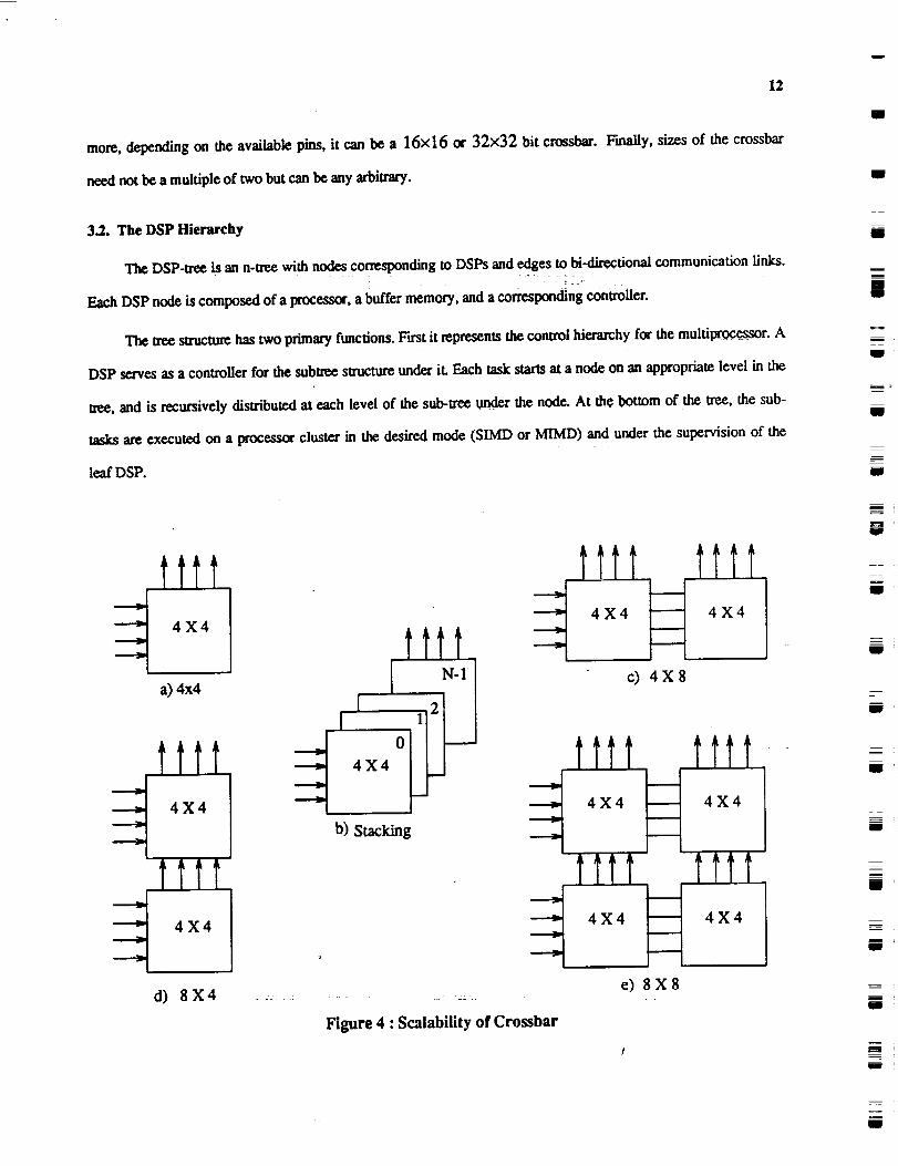
3.1.2. Scalability of Crossbar
Figure 4(a) depicts a 1 bit 4×4 crossbar switch. In order to obtain byte or word parallel crossbar, the crossbar
switches can be stacked together as shown in figure 4(b). The control, address and communication pattern informa-
tion is exactly the same in all the stacked switches. Figure 4(c),(d) and (e) illustrate the size scalability. Figure 4(c)
shows how a 4×8 crossbar can be obtained from two 4×4 crossbars. Similarly, figure 4(d) and (e) illustrate how
8×4 and 8X8 crossbars can be obtained respectively. Note that the smallest switch need not be a bit crossbar.
Depending on the technology and availability of the I/O pins, it can be of any size (such as 4 bit or a byte). Further-
w
12
more, depending on the available pins, it can be a 16x16 or 32x32 bit crossbar. Finally, sizes of the crossbar
need not be a multiple of two but can be any arbitrary.
3.2. The DSP Hierarchy
The DSP-tree is an n-tree with nodes corresponding to DSPs and edges to hi-directional communication links..... :: =: :::_:
Each DSP node is composed of a process_, a buffer memory, and a corresponding controller.
The tree structure has two primary functions. First it represents the control hierarchy for the multi_r. A
DSP serves as a conwoller for the subtree structure under iL Each task starts at a node on an appropriate level in the
t_e, and is recursively distributed at each level of the sub-tree under the node. At the bottom of the tree, the sub-
tasks are executed on a processor cluster in the desired mode (SIMD or MIMD) and under the supervision of the
leaf DSP.
m
J
g
R
I
g
U
m
tttt
4X4 tttt
a) 4x4 [ N-1
I[
otttt ,x,
4 X 4 b) Stacking
d) 8X4
lift tilt
4X4 _ 4X4
c) 4X8
t.ttt tttt4X4 4X4
tttt tttt
Ie) 8X8
Figure 4 : Scalability of Crossbar
U
g
Im
m
g
Q
i
i

r_w
13
The second function is that of disu%ufing the programs to leaf DSPs and the PEs. Vision algorithms are
charac_rized by a large number of identical parallel processes that exploit the spatial parallelism and operate on dif-
fexentdatasets.ItwouldbehighlywastefulifeachPE issueda sepam_ requestforitscopyoftheprogramblock
totheglobalmemory becauseitwould resultinhuge unnecessarytraffic throughtheinterconnecrlonnetwork.
UndertheDSP-hierarchyapproach,onecopyoftheprogramisfetchedbythecontrollingDSP (theDSP attheroot
ofthetasksubtre_)and thenbroadcastdown thesubtr_totheselectedPEa.Also,DSP hierarchyprovidescom-
municationpathsbetweenclusterstoIransferconlzolinformationordatafromone clustertoothers.Finally,the
DSP-treeisresponsibleforGlobalMemory management.
3.3. Global Memory
The multiport global memory is a parallel-pipelined sa,ucture as introduced in [28]. Given a memory(chip)-
access-time of T processor-cycles, each line has T memory modules. It accepts a request in each cycle and responds
after a delay of T cycles. Since an L-port memory has L lines, the memory can support a bandwidth of L words per
cycle.
Data and programs are organized in memory in blocks. Blocks correspond to "units" of data and programs.
The size of a block is variable and is determined by the underlying tasks and their data swuctures and data require-
ments. A large number of blocks may together constitute an entire program or an entire image. Memory requests
ate made for blocks. The PEs and DSPs are connected to the Global Memory with a multistage interconnection
network.
The global memory is capable of queuing requests made for blocks that have not yet been written into. Each
line (or port) has a Memory-line Controller (MLC) which maintains a list of read requests to the line and services
them when the block arrives. It maintains a table of tokens co_nding to blocks on the line, together with their
length, virtual address and full�empty status. The MLC is also responsible for virtual memory management func-
t/ons.
Two main functions of the global memory are input-output of data and program to and from the DSPs and
processor clusters, and to provide intercluster communication between various tasks as well as within a task if a task
is mapped onto more than one cluster.

14
3.4. Global Interconnection
The PEs and the DSPs are connected to the Global Memory using a multistage circuit-switching interconnec-
tion network. Data is transferred through the network in pages. A page is wansferred from the global memory to the
processors which is given in the header as a destination port address and the header also contains the starting
address of the page in the global memory. When the data is written into the global memory, only starting addressL
needs to be stated. In each case, end-of-page may be indicated using an exwa flag bit appended to each word.
We are evaluating an alternative strategy to connect DSPs, clusters and the global memory using a high speed
bus. In this organization one port of each cluster will be connected to the high speed bus. Also, each DSP will be
connected to the bus. Processors that need to communicate with processors in other clusters use explicit messages
to send and receive data from the other processors. Figure 5 illustrates this method. A processor Pi in cluster Ci
can send data to a processor Pj in cluster Cj as shown in the figure. Pi sends the data to the DSPi which sends the
data to DSP j in a burst mode. DSPj then sends the data to the processor P j. We are evaluating both alternatives
for intercluster communication.
GLOBAL BUS
M
E
M
0
R
Y
k
DSPi """
Ci cj
Figure 5 : An Alternative Strategy for Inter-Cluster Communication
I
g
IB
m
m
iii
N
i
W
I
i
i
D
t
i
Q
gl
w
r __J
W
w_
w
r_
15
3.5. IVS Computation Requirements and NETRA
In the following discussion we examine NETRA's architecture in the fight of requirements for an 1VS dis-
cussed in the previous section.
Reconfigurability (Computation Modes)
The clusters in NETRA provide SIMD, MIMD and systolic capabilities. As we discussed earlier, it is desir-
able to have these modes of operations in a multiproeessor system for IVS so that all levels of algorithms can be
executed efficiently. For example, consider matrix multiplication operation. We will show how it can be performed
in SIMD and systolic modes. Let us assume that the computation requires obtaining matrix C = A xB. For simpli-
city, let's assume that the cluster size is P and the matrix dimensions are PxP. Note that this assumption is made to
simplify the example description. In general, any arbitrary size computation can be performed independent of the
data or cluster size.
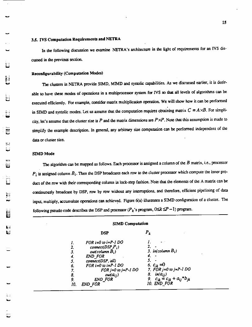
SIMD Mode
The algorithm can be mapped as follows. Each processor is assigned a column of the B matrix, i.e., processor
Pi is assigned column Bi. Then the DSP broadcasts each row to the cluster processor which compute the inner pro-
duct of the mw with their corresponding column in lock-step fashion. Note that the elements of the A matrix can be
continuously broadcast by DSP, row by row without any interruptions, and therefore, efficient pipelining of data
input, multiply, accumulate operations can achieved. Figure 6(a) illustrates a SIMD configuration of a cluster. The
following pseudo code describes the DSP and processor (Pt's program, 0<..k <_P-l) program.
=
SIMD Computation
DSP Pk
1. FOR iffiOto i=P-I DO 1.
2. connect(DSP,P i) 2.3. out( coiwnn B i) 3. in(column B i)4. END FOR 4.5. connect(DSP, all) 5. -6. FOR i=0 to i=P-I DO 6. Cik =07. FOR j=O to j=P-1 DO 7. FOR j=O to j=P-1 DO8. out(aij) 8. in(a U)9. END_FOR 9. Cik ----Cil_+ a U-bit10. END FOR 10. END FOR

16
In the above code, the computation proceeds as follows. In first three lines, the DSP connects with each pro-
cessor through the crossbar and writes the column on the output port. That column is input by the corresponding
processor. In statement 5, the DSP connects with all the processors in a broadcast mode. Then from statement 6
onwards, the DSP broadcasts the data from matrix A in row major order and each processor computes the inner pro-
duct with each row. Finally, each processor has a column of the output matrix. It should be mentioned that the above
code describes the operation in principal and does not exactly depict the timing of operations.W
Systolic Mode
The same computation can be performed in a systolic mo¢le. The DSP can reconfigure the cluster in a circular
l/near array after distributing columns of matrix B to processors as before. Then DSP assigns row Ai of matrix A to
processor Pi. Each processor computes the inner product of its row with its column and at the same time writes the
element of the row on the outout POre. This element of the row is input to the next processor. Therefore, each pro-
cessor receives the rows of matrix A in a systolic fashion and the computation is performed in the systolic fashion.
Note that the computation and communication can be efficiently pipelined. In the code, it is depicted by statements
7-10. Each element of the row is used by a processor and immediately written on to the output port, and at the same
time, the processor receives an element of the row of the previous processor. Therefore, every P cycles a processor
computes new element of the C matrix from the new rows it receives every P cycles. Again, note that the code
describes only the logic Of the computation and does not include the timing information. Figure 6(b) illustrates a
systolic configuration of a cluster,
ilp
ms
i
I
m
i
i
i
I,
2.3.4.5.6.7.8.9.I0.11.
Systolic Computation
DSP Pi
FOR i--O to i--P-1 DOconnect(DSP,P i)
out(column B i)out(row A i)
END FOR
co71_ct(Pi to Pi+l mod P)
I°
2.
3. in(column B i)4. in(coluran Ai)5.
6. c_i=O
7. FOR j=O to j--P-1 DO
8. Cii -- Cii 4" aij*b_i9. out(aij), in(ai-lj/10. END FOR -11. repeat 7-10for each new row
II
i
i
i :u
g
g
I

m
17
In a companion paper we present several examples of mapping different algorithms in different modes on the
clusters as well as their performance evaluation.
v
w
E ,
w
m
Partitioning and Resource Allocation
There are several tasks with vastly different characteristics in an IVS, and therefore, the number of processors
needed for each task may be different and may be needed in different computational modes. Hence, partitionability
and dynamic resource allocation are keys to high performance. Pardoning in NETRA can be achieved as follows.
When a task is to be allocated, the set of subtrees of DSPs is identified such that the required number of PEs is avail-
able at their leaves. One of the subtrees is chosen on the basis of characteristics of the task. The chosen DSP
represents the root of the control hierarchy for the task. Together with the DSPs in its subtrce, it manages the execu-
tion of the task. Note that partitioning is only virtual. The PEs are not required to be physically isolated from the rest
of the system. Once the subtree is chosen, the processes may execute in SIMD, MIMD or systolic mode. The fol-
lowing are some of the advantages of such a scheme. F'wsdy, only one copy of the programs needs to be fetched
thereby reducing the traffic through the global interconnecfion network. Secondly, simple load balancing techniques
my be employed while allocating tasks (examples are discussed in a companion paper). The tasks of global
memory management can be distributed over the DSP tree by assigning it to the DSP at the root of the subtree exe-
cuting the subtask. Finally, locality is maintained within the control hierarchy, which limits the intratask
DSP
f
...a) SIMD Mode
I--.,__ • • • ----__
b) Systolic Mode
Figure 6 : An Example of SIMD and Systolic Modes of Computation in a Cluster

18
communication to within the subm_.
Load Balancing and Task Scheduling
Two levelsof loadbalancingneed tobe employed, namely,globalload balancingand localload balancing.
Global load balancinga/ds in partitioningand allocatingthe resourcesfortasksas discussedearlier.Local load
balancingisused todisu'ibutecomputations(ordam) toprocessorsexecutingsubtasksofa largertask.Local load
balancingcan be eitherstaticor dynamic or a combinationof both. With staticload balancing,given a task,its
associateddataand the number of processorsallocatedforthe task,thedataispartitionedinsuch a way thateach
processorgetsequal or comparable amounts of computation [27].In dynamic load balancing,the subtasksare
dynamicallyassignedto theprocessorsasand when they finishthe previouslyassignedtasks.In NETRA when a
taskisassignedtoa subu-e_,theDSPs involvedperformthelocalloadbalancingfunctions.
Using the informationfrom localload balancingand othermeasures of computation,globalload balancingi - L : T ' T
can be achieved hierarchically by using the DSP hierarchy. In this scheme, each conl_ller DSP sends its measure of
load to its parent DSP and the root DSP receives the load information for the entire system. The root DSP then
broadcasts the measure of load of the entire system to the DPSs. When a task is to be allocated, these measures can
be used to select a subtree for i_ execution as follows: If any subtree corresponding to the child of the current DSP
has an adequate number of processors then the task is transfe_ to a child DSP with the lowest load, else if the
current subtree has enough resources and the load is not significantly greater than the average system load then the
task is allocated to the current sublree, else the current DSP transfers the task to the parent DSP.
Flexible Communication
Availability of flexible communication is critical to achieving high performance. For example, when a parti-
tion operates in SIMD mode there is a need to broad_t the programs. When a partition operates in MIMD mode,
where processors in the partition cooperate in the execution of a task, one or more programs need to be transferred
to the local memories of the processors. Performing the above justifies the need for selective broadcast capability. In
order to take advantage of spatial parallelism in vision tasks processors working on neighboring data need to com-
municate fast amongst themselves for high performance. The programmability and flexibility of the crossbar pro-
vide fast local communication. Most common vision algorithms such as FFTs, filtering, convolution, counting,
transforms, etc., need a broad range of processor connectivities for efficient execution. These connectivities include
g
g
mIll
m
I
m
i
g
mii
mm
iN
iN
m
m
m
W
iN
i
m
m
w
w
rw
w
lmmww
19
arrays, pipelines, several systolic configurations, shuffle-exchanges, cubes, meshes, pyramids e_. Each of these con-
nectivities may perform well for some tasks and badly for others. Therefore, using a crossbar with a selective broad-
cast capability, any of the above configurations can be achieved, and consequently, optimal performance can be
achieved at the clusters.
Several techniques for implementing reconfigurabUity between a set of PEs were studied [29, 30]. It was
discovered that using a crossbar switch to connect all PEs was simpler than any other schemes. The popular argu-
ment that crossbar switches are expensive was easily thwarted. When designing communication networks in VLSI,
the primary constraint is the number of pins and not the chip area. The number of pins is governed by the number of
ports on the network and is independent of the type of network. Fmlhermore, it was realized that a crossbar with a
selective broadcast capability was not only very powerful and flexible structure, but was also simpler, scalable and
less expensive.
The need for global communication is relatively low and infrequenL Global communication is needed for
intertask communication, i.e., from one task to another in the IVS pipeline. It is also needed to input and output data,
to Iransfer data within a subsystem when a task is executed on more than one cluster, and finally, it is needed to load
the programs. The most important issue in global communication is that the network speed should be matched with
the crossbar speed as well as with the processors speed. The global communication is performed through the global
memory using the interconnection network, or using the DSP hierarchy. Another alternative we consider is connect-
ing all the clusters and DSPs to a global bus. Since the DSPs perform most control functions and loading of pro-
grams and data, the responsibility of intertask communication does not lie with hierarchy. In a Section 5 we present
an extensive analysis of the global communication networks in NETRA. Then using the analysis developed here we
present performance of several algorithms in a companion paper.
4, Mapping Parallel Algorithms
There are two main considerations in mapping the parallel algorithms. First, mapping individual tasks or
algorithms, and the second, integration of various tasks. Mapping individual tasks involves efficient division of the
task(s) on the available processors, intratask communication, load balancing and, input and output of data. If the
task is mapped onto more than one processor cluster then the mapping will reAluire both intra-cluster as well as
inter-cluster communication. Integration of algorithms involves intertask communication, data transfer between

2O
tasks, formatting the data for the next task, and global load balancing.
The methodology we use for mapping parallel algorithms is multi-dimensional divide-and-conquer with
medium to large grain parallelism. An individual task (in the following discussion task and algorithm are used inter-
changeably) can be efficiently mapped using spatial parallelism because most of the vision algorithms are performed
on two dimensional data. However, integration of tasks involves exploiting both spatial as well as temporal parallel-
ism. Temporal parallelism can be exploited by recognizing intertask data dependencies. In NETRA, by providing
virtual partitioning of processors, refonfignrability, flexibili_ of communication and _stributed control, it is possi-
ble with much ease to exploit temporal parallelism available in integrated vision systems. Furthermore, temporal
parallelism can be improved by making data available to the next task in the pipeline as soon as it is produced by the
previous task. This is achieved using the macro data flow approach between tasks.
4.1.. Classification of Common Vision Algorithms
: " _ 77
We can classify some of the common vision algorithms according to their communication requirements when
mapped onto parallel processors. The classification provides an insight to the performance of an algorithm depend-
ing on its communication requirements.
(1) Local Fixed - In these algorithm, the output depends on a small neighborhood of input data in which the
(2)
(3)
neighborhood size is normally fixed. Sobel edge detection, image scaling and, thresholding are examples of
such algorithms.
Local Varying - Like the local fixed algorithms, the output at each point depends on a small neighborhood of
input data. However, the neighborhood size is an input parameter and is independent of the input image size.
Convolutions, edge detection and most other filtering and smoothing operations are examples of such algo.
rithms.
Global Fized - In such algorithms each output point depends on the entire input image. However, the compu-
ration is normally input data independent (i.e., computation does not vary with the type of image and only
depends on the size of the image). Two Dimensional Discrete Fourier Transform and Histogram computation
are examples of such algorithms.
(4) Global Varying - Unlike global fixed algorithms, in these algorithms the amount of computation and commun-
icadon depends on the image input as well as its size. That is, the output may depend on the entire image or
U
m
W
Iil
11
==
i
g
m
g
m
g
II
mm
m
I
lib
ill
II

w
w
7_
=
w
w
= =w
21
may depend on a part of image. In other words, the computation is data dependent. Hough Transform and,
Connected Component Labeling are examples of such algorithms. In an image, a connected component may
span only a small region, or in the worst case the entire image may be one connected component (a spiral).
Similarly, in case of the Hough transform for detecting lines, a line may span across image (meaning its votes
must come from distant pixels or edges) or it may be localized.
,1.2. Mapping an Algorithm on One Cluster
Mapping a task on one clustea"means that intratask communication will only involve communication between
processors of the same clusters. Figure 7 shows how a parallel algorithm is mapped on a cluster. Let us assume that
there are P processors in a cluster. As shown in figure 7, first program and data are loaded onto the processor cIus-
tea'. Both in case of SIMD or IMD mode, the program is broadcast onto the cluster processors. The data division
depends on the particular algorithm. If algorithms are mapped in SIMD or systolic mode then the compute and
communication cycles will be intermixed. If the algorithms are mapped in MIMD mode then each processor com-
putes its partial results and then communicates with others to exchange or merge data.
Let us assume that an algorithm is mapped on one cluster with P processors. The total processing time in such
a mapping consists of the following components. Program load time onto the cluster processors (tp/), data load and
partitioning time (td/), computation time of the divided subtasks on the processors (tcp) which is the sum of the
maximum processing time on a processor Pi and intra-cluster communication time (tcomm), and the result report
time (trr). tdl consists of three components: 1) data read time from the global memory (tr) by the cluster DSP, 2)
crossbar switgh setup time (tsw) and, 3) the data broadcast and distribution time onto the cluster processors (tbr).
The total processing time x(P) of the parallel algorithm is given by
x(P) = tpt + + tq, + t,, (3)where,
tdt = t, + t t,,e + tb, (4)and if the computation and communication do not overlap then,
tq, = MAX (tei) + tcomm (5)lai._
else if computation and communication can completely overlap then,

22
tg
ProgramLoad
I tdtw
m
Compute
P1
Communi-
cation
Compu_
P2
Communi-
cation
Compute
Communi-
_fion
Result trrOutput
I Next Ta.._qk
Figure 7 : Mapping Algorithms on One Cluster
tcp= MAX ( MAX (tpi) , room, )l$i gP
In the above equations tr depends on the effective bandwidth of the global interconnection network.
(6)
4.3. Mapping an Algorithm on More than one Cluster
If an algorithm is mapped on more than one cluster then the communication consists of intra-cluster commun-
ication as well as inter-cluster communication. Since the cost of inter-cluster communication is more than that of
inwa-cluster communication, the inter-clustex communication should be minimized while mapping a parallel algo-
rithm on more than one cluster. Figure 8 shows how a typical algorithm will be mapped onto two clusters.
Figure 5 shows how processor Pi in cluster Ci will communicate with processor Pj in cluster Cj using the- " 7
global bus. The communication will be performed explicitly by messages. Processor Pi will send the clam and the
identification of the receiving processor to its DSP (DSPi). The DSP then will forward the message to the
corresponding DSP in the other cluster (DSPj). DSPj will send the data to Pj. A processor Pi in cluster Ci will
communicate with a processor Pj in cluster Cj using the global memory as shown in figure 9. Processor Pi will
u
B
I
I
1ig
m
J

w
23
Next
Task
TASK
Program I ProgramLoad Load
Next TaskNext Task
Next
I'ask
Figure 8 : Mapping Algorithms on Multiple Clusters
write the data into a specified memory location in the global memory using its port connected to the multistage inter-
connection network. Processor Pj will request for the data from the Memory Line Controller on its port connected
to the interconnection network. The basic difference between the two approaches is the available bandwidth through
the global interconnection. In case of the bus, the effective bandwidth will be much lower compared to the effective
bandwidth of the multistage interconnection network because only one processor or DSP can access the bus at a
time.
The performance of the algorithm mapped on more than one cluster depends on how much inter-cluster corn-
munieation is required and by how many processors, which in tm'n depends on the type of algorithm. Figure 9 illus-
trates various ways in which an algorithm can be mapped on two or mote clusters. However, in the figure we only

24
show two clusters. Case a) represents the best case in which a parallel algorithm can be mapped such that only one
or no processors need to communicate with any processor in the other cluster. This is obtained by partitioning the
data in such a way that only one processor in each cluster gets the boundary data and the algorithm is such that corn-
munication is only exchanging boundary values. Example of such algorithms include local fixed and local varying
algorithms.
In an average case, some of the processors in one cluster are required to communicate with processors in the
other cluster. Case b) in Figure 9 illustrates such a case. The figure shows that data processed by a few processors is
needed by corresponding processors in the other cluster. However, the figure does not show how the transfer of the
data will take place. That depends on the chosen global interconnection network and how the algorithm is mapped.
Global varying algorithms may need this type of communication. For example, the connected component labeling
algorithm can be mapped in such a way that only those processors need to communicate across clusters which have
boundary components.
U
I
U
B
g
U
D
C1
C2
e/I
P]
Pn
Best Case
C1
C2
! ! !
i | ipI I I tl
I ! I
I ! !
PI I _ i A
! !
I ! !
! !
i I lpI I 1 /11
I _1 I
Average Case
I
!
I
C! !!e_:
! !
!
C2 PI:l
I
I
I I I
I
I
I
I
I
I
! !
! ! I
Worst Case
| I !
I I I
I I I
I I I
I I I
I I I! t P/'ll !
!
!
!
!
I
!
! !
Figure 9 : Types of Intercluster Communication
mlP
i
I
U
U
I
im
i

w
qr¢o
w
D-°
m_F .
z
w
25
The third case (c) represents the worst case. The worst case means that data produced by each processor is
required by at least one processor in another cluster. Global fixed and some global varying algorithms need this
typeofcommunication.
Now, letusdiscusshow inter_lustercommunicationisincorporatedintheperformanceofan algorithm.Let
usassumethatan algorithmismapped on C clusters.The totalcomputationtimeforan algorithm(EQ.5)isnow
given by
tcp MAX ( MAX (tt, i) ) + tcomm (7)I<j<C O_i_P
now, tcomm is given by
t_o#_ = t_ + ticz (8)
where, tct represents the inu'a-cluster communication time and, tict denotes the inter-cluster communication time.
ticl not only depends on the type of algorithm, how it is mapped, how many clusters it is mapped on but also
depends on the effective bandwidth of the global interconnection. The effective bandwidth depends on the commun-
ication requirements of the other tasks in the system which may be executing on other clusters. Let us assume that
t_=t denotes the communication time when there is no interference in the interconnection network, that is, tct
denotes the data write and read time given that the network is available whenever inter-cluster communication is
needed. Then the actual inter-cluster communication will be degraded by a factor w which depends on the traffic
intensity in the network and the interference by communication of other tasks in the system. Therefore, instead of
ticl, the inter-cluster communication time will be w×ticI.
$. Inter-cluster Communication in NETRA
Communication between processors within the same cluster is performed using the crossbar connections.
Communication between processors in different clusters can be performed in various ways. First, the global memory
is used for this purpose as follows. The processor(s) needing to send data to another processor in a different cluster
writes the data into designated locations in the memory. This involves setting the appropriate circu/t through the glo-
bal multistage interconnection network to the memory module followed by a data transfer. The data is transferred in
block mode. The Memory Line Controller (MLC) updates the information about the destination port(s), the length
of the data block, block's starting address and sets a flag indicating the availability of the data. Now, the destination
processor can read the data using this information. Note that this method permits out of order requests to be ser-

26
viced. For example, if the destination processor tries to read the dam before it has been written, MLC informs the
processor of this situation and when the data is really wriuen into the global memory then the MLC informs the des-
tination processor. This is a block level data-flow approach. The main advantages of this approach are that asyn-
chronous communication is possible, out of order messages can be handled and efficient pipelining of data can be
achieved.
The second alternative to perform inter-cluster communication is to use the DSP tree links. However, for dis-
tam inter-cluster communications, the tree may not perform well because of the root bottlenecks typical to any tree
structure. The main function of the tree structure is to provide control hierarchy for the clusters. Its links are mainly
used for program and data broadcast to subtrees, and DSPs use the tree links to send (receive) control information to
(from) other DSPs.
The third alternative strategy to perform inter-cluster communication is to use a high speed global bus that
connects all DSPs and one port from each cluster. The global memory is also connected to the bus and is accessible
to all the clusters via the bus. The communication is done explicitly by messages and synchronously. Figures 10 and
5 show the first and third communication methods. The figures show how a processor Pi of cluster Ci will com-
municate with processor Pj of cluster Cj using the two strategies.
Inter-cluster communication is needed in the following cases : i) An algorithm is mapped in parallel on more
than one cluster and the processors need to communicate to exchange partial results or combine their results, ii) in
C -tl- t- -tC_ c C c c c
I11[. -
i ll li l JIiII IK:I Figure 10 : Inter-Cluster Communication Using Global Memory
w
m
m
b
nllJ
IB
m
I
I
ii
l
i
M
i
i
IIS
L_
= ;
r _
_r
27
an integratedvisionsystem,outputdataof a taskproducedat oneor more clustersneedsto be wansferredto thenext
task executing on different clusters and, iii) to perform input and output of data and results.
The extent of inter<luster communication depends on the type of algorithms, how they are mapped in paral-
lel, frequency of communication and amount of data to be communicated.
$.1. Analysis of Inter-Cluster Communication
There are several parameters that affect the inter-cluster communication time. The architecture dependent
parameters are: number of processors (i.e., number of clusters and number of processors in each cluster), number of
memory modules, number of processors per port connected to the global interconnection, and the type of intercon-
nection network. Some parameters depend both on the architecture as well as on the type of algorithms, how they
are mapped, their communication requirements when mapped onto multiple clusters etc. Furthermore, not only does
the communication time depend on the underlying algorithms but also on the network traffic generated by other pro-
cessors in the system because there may be conflicts in accessing the network as well as memory modules.
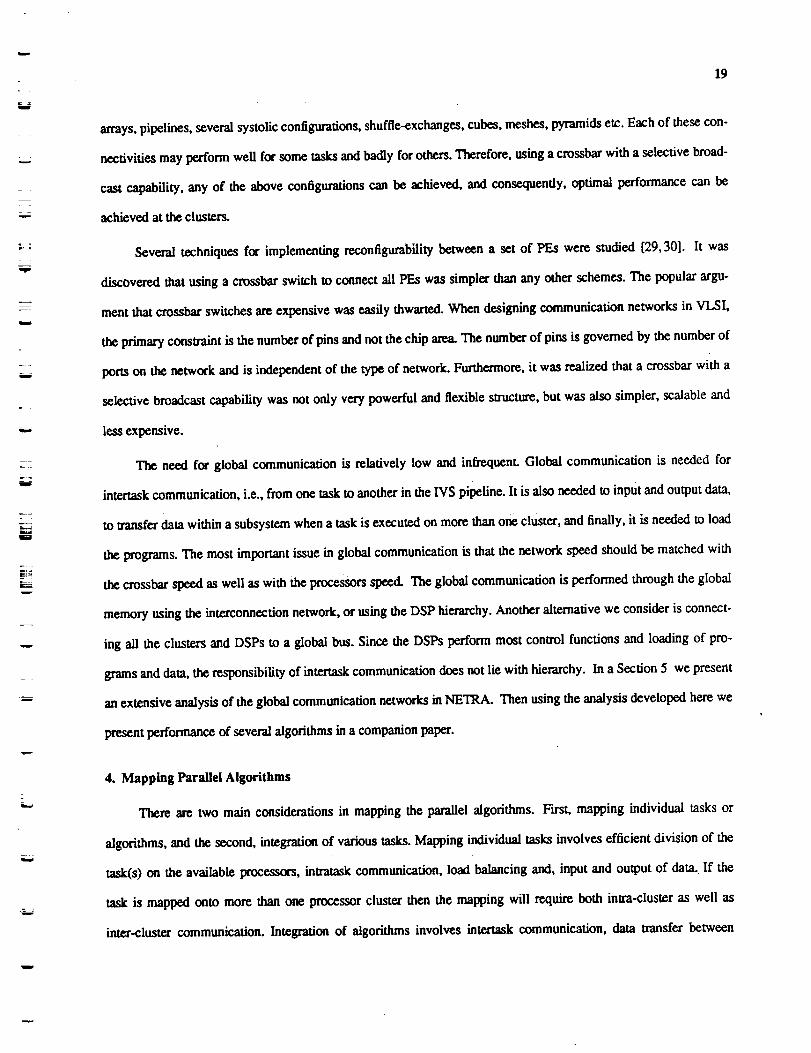
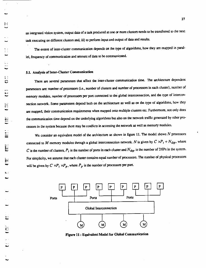
We consider an equivalent model of the architecture as shown in figure 11. The model shows N processors
connected to M memory modules through a global interconnection network. N is given by C xP t + Ndsp, where
C is the number of clusters, Pt is the number of ports in each cluster and Ndsp is the number of DSPs in the system.
For simplicity, we assume that each cluster contains equal number of processors. The number of physical processors
will be given by C xP t xPp, where Pp is _ number of processors per port.
Ports
Figure 11 : Equivalent Model for Global Communication

28
The followinganalysisisbasedon theanalysispresentedby Patelin[3I,32].He developedan analytical
model for evaluating alternative processor memory intcrconnection performance and showed that the analysis is lea-
sonably accurate. Consider execution of a typical parallel algorithm on multip!9 clus_. The execution will consist
of processing, intra-cluster communication and inter-cluster communication. Figure 12 shows the computation and
.communication phases of an algorithm. The computation time is given by top, the intra-cluster communication time
is given by tcl, and the inter-cluster communication time is given by ticl in terms of equivalent processor cycles.
However, due to conflicts in the network or in memory modules, a processor may have to wait for w a cycles before
being able to access the network and write to (or read from) the memo_. In effect, this can be seen as the communi-
cation time being elongated by a factor w for each request, and instead of it being tier, it is now wY, tic I as shown in
figure 12. Therefore, if the probability of accessing the global network in each processing cycle is m and for each
access the communication time is ticl, then the useful computation for t processor cycles takes t + m×t×w×licl,
where t =tcp +tel. The fraction of useful work (utilization U) is given by
tU=
t + mxt×wxt_:t
The average number of busy memory modules
(9)
(or fraction of time when the bus is busy when the global intercon-
nection is a bus) is
Nxmxt_lxtB=
t + mxt_:txt×w
and in terms of utilization,
(I0)
D
m#l#
i
m
D
g
l
i
g
IB
tc_ +tot
No Interference
tcp + ta wxtia
]l]]lllI[l ll IIIWith Interference
Figure 12 : Computation and Communication Activities of a Processor
M
i
i
N
m
mg
g
Ill

L_
=
L=
29
B = NxmxtictxU (11)
In [31] it is shown that the utilization primarily depends on the product m×ticl rather than m and ticI indivi-
dually. In other words, the processor utilization primarily depends on the traffic intensity and to a lesser extent on
the nature of the traffic.
For a particular algorithm, all the parameters are known except w. The probability of accessing the global
network is essentially given by the number of times communication is needed per processor cycle and is known
when an algorithm is mapped in parallel. The factor w depends on the algorithm parameters as well as the interfer-
ence from other processors accessing the global network and the memory, number of processors, number of
memory modules, the type of interconnection network and the access rate m.
Consider the processor activities again. A processor needing to access the global memory or the bus submits
requests again and again until accepted; on an average this happens for (w-1)×t/c/time units. After the request is
granted, the processor has a path to memory for tict fame urfits. In other words, the network sees an average of
WXlic l consecutive requests for unit service time. Therefore, the request rate (for unit service) from a processor as
seen by the network is
m×w×t_tm'= . (12)
1 + m ×w×tic 1
and in terms of utilization
m'= 1 -U.
For details, the reader is referred to [31].
The model that we analyze is a system of N sources and M destinations. Each source generates a request with
probability m" in each unit time. The request is independent, random, and uniformly distributed over all destina-
tions. Each request is for one unit service time. The following is an analysis for a bus and for multistage delta net-
WOrk.
Bus : We know from earlier discussion that
B = NxmxtidxU (13)
and also, assuming all sources have the same request rate, average amount of time the bus is busy is given by
B=[ 1-(1-m'_ ]. (14)

3O
The equations 12 and 13 result in a non-linear equation
NxmxtictxU - [ 1 - ( 1 - m" )N =0. (15)
In the above equation, value of m' can be substituted in terms of w, and hence, value of w can be computed.
If the request rate from som_es is not uniform, i.e., ff the request rate from source Ni is mi then the above equation
becomes
(mixticl(,l')xUj) - [ 1 - (1 - m'j ) ] = 0. (16)jr1 j=l
When evaluating performance of a parallel algorithm mapped across clusters there will be two request rates,
one for the processors taking part in runing the algorithm and the other for rest of the processors in the system which
will be an input parameter.
Multistage-lnterconnectlon (Delta) : A delta network is an n stage network constructed from axb crossbar
switches with a resulting size of an×b n. Therefore, N = a n and M = bn. For:a:completer description refer to
[32]. Functionally, a delta network is an interconnection network which allows any of N sources (processors) to
communicate with any one of the M destinations (memory modules). However, two requests may collide in the net-
work even if the requests are made to different memory modules. We use results from[32,31] to obtain average
number of busy main memory modules B, which is given by
B = Mxmn (17)
and the following equation in satisfied.
N/,mxtictxU - Mxmn = 0 (18)
where,
mi
mi+l = 1 - ( 1 --_- )a O<i <n
too= 1-U.
For details, the reader is referred to [31,32].
These equations are solved numerically to obtain the interference delay factor w which is used in the perfor-
mance evaluation of algorithms mapped across multiple clusters.
u
m
m
J
IB
h
m
S
g
il
m
lib
R
D
m
I
i
m
t

w
31
5.2. Approach to Performance Evaluation of Algorithms
Performance of an algorithm mapped on multiple clusters is governed by various factors. Table 1, summarizes
the parameters affecting the performance of a parallel algorithm. The approach to evaluating the performance of an
algorithm is as follows. Using the parameters and a particular mapping, computation (tcp), intra-cluster communi-
cation (td) and inter-cluster communication time if/d) are determined. The traffic intensity for a processor(s) (or a
cluster depending on how an algorithm is mapped) is given byticl
tcp+td• Using the traffic intensity values, and using
a range of traffic intensity values for interference, the effective bandwidth of the network is determined, that is, the
factor w is computed. In a companion paper, we will present performance evaluation of several algorithms using the
above method.
Consider a parallel execution of an algorithm across clusters. If the execution time when the algorithm is exe-
cuted on a single processor is tseq then the speed up in the best case is given by
lseqSp - (19)
+ +
That is, assuming there is no interference while accessing the network or the global memory. Under the condi-
tions in which there are conflicts while accessing the network, the inter-cluster communication time will be given by
wxticl, and therefore, the speed up will be given by
Sp" = tseq% + tot+ wxt t
(20)
Table 1 : Parameters for Performance Evaluation
PCN
D
MGICN
mxt
mix/1
No. of proe. executing an algorithmOuster size
Total no. of proc, in the systemData size
No. of procJponNo. of memory modulesType of global intereonnectionTraffic intensity for interference in networkand memory acceSS by (N-P) processorsTraffic intensity for network andmemory access by partition executing the algorithm

32
Hence, degradation in speed up with respect to the best case speed up will be
Sp - Sp"= (w-l)xt :tSp + + wxt "
(21)
6. Summary
Inthispaperwe presentedamodelofcomputationforIVSs.Usingthemodel desiredfeaturesand capabili-
ties of a parallel architecture for IVSs were derived. Then a multi_r architecture suitable for IVS (called
NETRA) was presented. The topology of NETRA is recursively defined and, hence is easily scalable from small to
large systems. Homogeneity of NETRA permits fault tolerance and graceful degradation under faults. NETRA is a
recursively defined tree-type hierarchical architecture whose leaf nodes consist of cluster of processors connected
with a programmable cro__bar with selective broadcast capability to provide for desired flexibility. We presented a
qualitative evaluation is NETRA. Then general schemes were described to map parallel algorithms onto NETRA.
Finally,an analysistoevaluate alternative inter-clustercommunicationstrategies_ NETRA was presentedwitha
methodology to evaluate performance of parallel algorithms mapped across multiple clusters.
In a companion paper (part II of this paper) we present performance evaluation of several common vision
algorithmson NETRA. The paperdiscussesperformanceofalgorithmson onecluster,theiranalysisandimplemen-
tation.Furthermore, the paper includes performance evaluation of alternative communication strategies as well as
presentsmappingofalgorithmsacrossmultipleclusters.The effectofinterferenceintheglobalinterconncctionnet-
work and global memory on the performance of algorithms is also studied.
1
I
I
I
i1
I
t
uI
I
i
I
z
I
I
II
U
i
I

REFERENCES
33
[1] M. Sharma, J. H. Patel, and N. Ahuja, "NETRA: An architecture for a large scale multiproccssor visionsystem," in Workshop on Computer Architecture for Pattern Analysis ans Image Database Management,Miami Beach, FL, pp. 9'2-98, November 1985.
[2] Alok C_udhary, Janak Patel, and Narendra Ahuja, "NETRA - A paralld architecture for integrated visionsystems H: algorithms and performance evaluation," IEEE Transactions on Parallel and DistributedProcessing (submitted), August 1989.
[3] J.L. Bentley, "Multidimensional divide-and-conquer," Communications of the ACM, vol. 23, pp. 214-229,April, 1980.
[4] C. Wee,ms, A. Hanson, E. Riscman, and A. Rosenfeld, "An integrated image understanding benchmark:recognition of a 2 1/2 D mobile," in International Conference on Computer Vision and Pattern Recognition,Ann Arbor, MI, June 1988.
[5] M.J.B. Duff, "CLIP 4: a large scale integrated circuit array parallel processor," IEEE Intl. Joint Conf. OnPattern Recognition, pp. 728-733, November 1976.
[6] M.J.B. Duff, "Review of the CLIP image processing system," in National Computer Conference,Anaheim, CA, 1978.
[7] L. Cordelia, M. J. B. Duff, S. Levialdi, "An analysis of computational cost in image processing: a casestudy," IEEE Transactions on Computers, vol. c-27, no.10, pp. 904-910, 1978.
[8] K. Bateher, "Design of a massively parallel processor," IEEE Transactions on Computers, vol. 29, pp.836-840, 1980.
[9] T. Kushner, A. Y. Wu, and A. Rosenfeld, "Image processing on MPP:.I," Pattern recognition, vol. 15,, pp.120-130, 1982.
[10] J.L. Potter, "Image processing on the massively parallel processor," IEEE Computer, pp. 62-67, January1983.
[11] N. Ahuja and S. Swamy, "Multiprocessor pyramid architectures for bottom-up image analysis," IEEETransactions on Pattern Analysis and Machine Intelligence, vol. PAMI-6, pp. 463-475, July 1984.
[12] V. Cantoni, S. Levialdi, M. Ferretti, and F. Maloberti, "A pyramid project using integrated technology," inIntegrated Technology for Parallel Image Processing, London, pp. 121-132, 1985.
[13] A. Merigot, B. Zavidovique, and F. Devos, "SPHINX, A pyramidal approach to parallel image processing,"IEEE Workshop on Computer Architecture for Pattern Analysis and Image Database Management, pp.107-111, November 1985.
[14] D.H. Schaefner, D. H. Wilcox, and G. C. Harris, "A pyramid of MPP processing elements - xperience andplans," Hawaii lntl. Conf. on System Sciences, pp. 178-184, 1985.
[15] S.L. Tanimoto, "A hierarchical cellular logic for pyramid computers," J. of Parallel and DistributedProcessing, vol. 1, pp. 105-132, 1984.
[16] S.L. Tanimoto, T. J. Ligocki, and R. ling, "A prototype pyramid machine for hierarchical cellular logic," inParallel Hierarchical Computer Vision, L. Uhr (Ed.), London, 1987.
[17] F.A. Briggs, K. S. Fu, J. H. Patel, and K. H. Huang, "PM4 - A reconfigurable multiprocessor system forpattern recognition and image processing," 1979 National Computer Conference, pp. 255-266.
[18] H.J. Siegel et al., "PASM - a partitionable SIMD/MMD system for image processing and patternrecognition," IEEE Transactions on Computers, vol. C-30, pp. 934-947, December 1981.
[19] Y.W. Ma and R. Krishnamurti, "The architecture of REPLICA - a special-purpose computer system foractive multi-sensory perception of 3_dimensional objects," Proceedings International Conference onParallel Processing, pp. 30-37, 1984.
[20] W.A. Perkins, "INSPECTOR - A computer vision system that learns to inspect parts," IEEE Transactionson Pattern Analysis and Machine Intelligence, vol. PAMI-5, pp. 584-593, November, 1983.

34
[21] H.T. Kung and L A. Webb, "Global operations on the CMU WARP machine," Proceedings of 1985 AIAAComputers in Aerospace V Conference, October 1985.
[22] T. Gross, H. T. Kung, M. Lain, and J. Webb, "WARP as a machine for low-level vision," in IEEE
International Conference onRobotics and Automation, ST. Louis, Missouri, pp. 790-800, March 1985.
[23] H.T. Kung, "Systolic algorithms for the CMU Warp processor," in Tech. Rep. CMU-CS-84-I58, Dept. ofComp. Sci., CMU, Pittsburgh, PA, September, 1984.
[24] F.H. Hsu, H. T. Kung, T. Nishizawa, and A. Sussman, "LINC: The link and interconnection chip," in Tech.Rep., Dept. of Comp. Sci., CMU, CMU-CS-84-I59, Pittsburgh, May i984. :=: .....
[25] M. Annatatone eL al., "The Warp computer : architecture, implementation, and performance," IEEEtransactions on Computers, December 1987.
[26] C.C. Wcems, S. P. Lavitan, A. R. Hanson, E. M. Riseman, J. G. Nash, and D. B. Shu, "The image
understanding architecture," COINS Tech. Rep. 87-76,
[27] M.K. Leung, A. N. Choudhary, L H. Patel, and T. S. Huang, "Point matching in a time sequence of stereoimage pairs and its parallel implementation on a multiprocessor," in IEEE Workshop on Visual Motion,Irvine, CA, March 1989.
[28] F.A. Briggs and E. S. Davidson, "Organization of semiconductor memories for parallel-pipelinedprocessors," IEEE Transactions on Computers, pp. 162-169, February 1977.
[29] D. Degroot, "Partitioning job structures for SW-banyan networks," Proceedings of the International
Conference on Parallel Processing, pp. 106-113,1979,
[30] H.J. Siegel, "Partitioning permutation networks : the underlying theory," Proceedings of the InternationalConference on Parallel Processing, pp. 175-184, 1979.
[31] Janak H. Patel, "Analysis of multipvocessors with private cache memories," IEEE Transactions onComputers, vol. C-31, pp. 296-304, April 1982.
[32] Janak H. Patel, "Performance of processor-memory interconnections for multiprocessors," IEEETransactions on Computers, vol. C-30, pp. 771-780, October 1981.
g
J
iI
U
m
g
m
M
m
U
m
U
mm
I
m
I
I
m
I
m
J