netlink 8000 series wireless telephone - unified
TRANSCRIPT
NetLink 8000 Series Wireless Telephone NetLink Telephony Gateway and SpectraLink Radio Protocol (SRP)
Configuration and Administration
Part Number: 72-1305-00 Issue A

SpectraLink Corporation Configuration and Administration–NetLink 8000 Series Wireless Telephone NetLink Telephony Gateway and SpectraLink Radio Protocol
Notice SpectraLink Corporation has prepared this document for use by SpectraLink personnel and customers. The drawings and specifications contained herein are the property of SpectraLink and shall be neither reproduced in whole or in part without the prior written approval of SpectraLink, nor be implied to grant any license to make, use, or sell equipment manufactured in accordance herewith.
SpectraLink reserves the right to make changes in specifications and other information contained in this document without prior notice, and the reader should in all cases consult SpectraLink to determine whether any such changes have been made.
The terms and conditions governing the sale of SpectraLink hardware products and the licensing of SpectraLink software consist solely of those set forth in the written contracts between SpectraLink and its customers. No representation or other affirmation of fact contained in this document including but not limited to statements regarding capacity, response-time performance, suitability for use, or performance of products described herein shall be deemed to be a warranty by SpectraLink for any purpose, or give rise to any liability of SpectraLink whatsoever.
In no event shall SpectraLink be liable for any incidental, indirect, special, or consequential damages whatsoever (including but not limited to lost profits) arising out of or related to this document, or the information contained in it, even if SpectraLink has been advised, knew, or should have known of the possibility of such damages.
Trademark Information SpectraLink® LinkPlus Link NetLink SVP Are trademarks and registered trademarks of SpectraLink Corporation. The SpectraLink logo is a registered trademark in the United States of America and in other countries. All other trademarks used herein are the property of their respective owners.
SpectraLink Corporation 5755 Central Avenue Boulder, CO 80301 303 440 5330 or 800 676 5465 www.spectralink.com
Copyright © 2007 SpectraLink Corporation. All rights reserved
Information in this document is subject to change without notice and does not represent a commitment on the part of SpectraLink Corporation. The software described in this document is furnished under a license and may only be used pursuant to the terms of (1) SpectraLink's software license agreement available at http://www.spectralink.com/softwareUpdates OR (2) the terms and conditions previously agreed to in writing between the user and SpectraLink Corporation OR (3) the terms and conditions previously agreed to in writing between the user and an authorized SpectraLink reseller (each, the “Agreement”). The software may be used only in accordance with the terms of the Agreement. No part of this manual, or the software described herein, may be reproduced or transmitted in any form or by any means, electronic or mechanical, including photocopying and recording, for any purpose except for the sole intent to operate the product or without the express written permission of SpectraLink Corporation.
PN: 72-1305-00-A.doc Page 2
SpectraLink Corporation Configuration and Administration–NetLink 8000 Series Wireless Telephone NetLink Telephony Gateway and SpectraLink Radio Protocol
WARNING: Changes or modifications to this equipment not approved by SpectraLink Corporation may cause this equipment to not comply with part 15 of the FCC rules and void the user’s authority to operate this equipment.
WARNING: SpectraLink products contain no user-serviceable parts inside. Refer servicing to qualified service personnel.
IMPORTANT SAFETY INFORMATION Follow these general precautions while installing telephone equipment:
• Never install telephone wiring during a lightning storm.
• Never install telephone jacks in wet locations unless the jack is specifically designed for wet locations.
• Never touch uninsulated telephone wires or terminals unless the telephone line has been disconnected at the network interface.
• Use caution when installing or modifying telephone lines
Please visit www.spectralink.com to view regulatory declarations.
PN: 72-1305-00-A.doc Page 3
SpectraLink Corporation Configuration and Administration–NetLink 8000 Series Wireless Telephone NetLink Telephony Gateway and SpectraLink Radio Protocol
Table of Contents 1. About This Document 5
1.1 SpectraLink Corporation Model Numbers 5 1.2 Related Documents 5 1.3 Contacting SpectraLink 5 1.4 Icons and Conventions 5
2. NetLink Wireless Telephone Overview 6 2.1 SpectraLink Voice Priority (SVP) and Quality of Service 6 2.2 NetLink Wireless Telephone Security 6 2.3 Quick Start Overview 7 2.4 NetLink Wireless Telephone Specifications 8 2.5 Handset Display 9 2.6 Startup Sequence 10 2.7 Handset Modes 11
3. NetLink Wireless Telephone Configuration 12 3.1 The Admin Menu 12 3.2 User-defined Preferences 21
4. Software License and Protocol Management 23 4.1 Requirements 23 4.2 Configuration Process 23
5. Testing the Handsets 25
6. Diagnostic Tools 26 6.1 Run Site Survey 26 6.2 Diagnostics Enabled 28 6.3 Syslog Mode 31
7. Certifying the Handsets 33 7.1 Conducting a Site Survey 33
8. Software Maintenance 34
9. Troubleshooting 35 9.1 Access Point Problems 35 9.2 Configuration Problems 35 9.3 Infrastructure Problems 36 9.4 Dial tone Problems 36 9.5 Handset Status Messages 37
PN: 72-1305-00-A.doc Page 4

SpectraLink Corporation Configuration and Administration–NetLink 8000 Series Wireless Telephone NetLink Telephony Gateway and SpectraLink Radio Protocol
1. About This Document This document explains how to configure and maintain the NetLink 8000 Series Wireless Telephones (handsets) when used with the NetLink Telephony Gateway.
1.1 SpectraLink Corporation Model Numbers This document covers the following model numbers:
802X, 803X
1.2 Related Documents NetLink Telephony Gateway: Installation, Configuration, and Administration (72-0065-02) NetLink SVP Server: Installation, Configuration, and Administration (72-0178-02) NetLink 8000 Series Wireless Telephones Handset Administration Tool (72-1304-00) NetLink 8000 Series Wireless Telephone and Accessories User Guide (72-1301-00) Available at http://www.spectralink.com/resources/manuals.jsp.
LinkPlus Interface Guide (72-0171-xx where xx indicates a number corresponding to the type of PBX) Available at http://www.spectralink.com/consumer/interface_guides.jsp.
NetLink Wireless Telephone WLAN Compatibility List (72-9000-00) Access Point Configuration Note (72-99xx-00 where xx indicates a number corresponding to the type of access point.). Available at http://www.spectralink.com/resources/wifi_compatibility.jsp.
Deploying NetLink Wireless Telephones: Best Practices paper. Available at http://www.spectralink.com/resources/white_papers.jsp.
1.3 Contacting SpectraLink SpectraLink wants you to have a successful installation. If you have questions please contact the Customer Support Hotline at (800) 775-5330. The hotline is open Monday through Friday, 6 a.m. to 6 p.m. Mountain time.
1.4 Icons and Conventions This manual uses the following icons and conventions.
Caution! Follow these instructions carefully to avoid danger.
Note these instructions carefully.
NORM This typeface indicates a key, label, or button on the NetLink Wireless Telephone (handset).
PN: 72-1305-00-A.doc Page 5

SpectraLink Corporation Configuration and Administration–NetLink 8000 Series Wireless Telephone NetLink Telephony Gateway and SpectraLink Radio Protocol
2. NetLink Wireless Telephone Overview NetLink 8000 Series Wireless Telephones are mobile handsets for workplace telephone systems. The handset operates over an 802.11a/b/g wireless Ethernet LAN providing users a wireless voice over IP (VoIP) extension. By seamlessly integrating with the NetLink Telephony Gateway and the facility’s telephone system, handset users are provided with high-quality mobile voice communications throughout the workplace. The handset gives users the freedom to roam throughout the workplace while providing all the features and functionality of a desk phone.
The handsets reside on the wireless LAN with other wireless devices using direct-sequence spread spectrum (DSSS) radio technology. The handset radio transmits and receives packets at up to 54Mb/s.
All SpectraLink products use the company’s LinkPlus integration technology to connect with various digital switch platforms. Using LinkPlus technology, handsets emulate digital telephone sets to deliver advanced capabilities such as multiple line appearances and LCD display features. See the LinkPlus Interface Guide for your PBX for information about mapping the PBX features to the handset.
2.1 SpectraLink Voice Priority (SVP) and Quality of Service SVP is the SpectraLink quality of service (QoS) mechanism that is implemented in the handset and an access point (AP) to enhance voice quality over the wireless network. SVP gives preference to voice packets over data packets on the wireless medium, increasing the probability that all voice packets are transmitted efficiently and with minimum or no delay. SVP is fully compatible with the IEEE 802.11 standards.
The NetLink SVP Server is an Ethernet LAN device that works with the APs to provide QoS on the wireless LAN. Voice packets to and from the handsets are intercepted by the NetLink SVP Server and encapsulated for prioritization as they are routed to and from an IP telephony server or gateway. See NetLink SVP Server: Installation, Configuration, and Administration for detailed information about this device.
When the system employs four or fewer NetLink Telephony Gateways without an NetLink SVP Server, the NetLink Telephony Gateway(s) provide SVP’s QoS. In this configuration, the handsets are limited to a maximum of 2Mb/s. If the 11Mb/s transmission rate is desired, a NetLink SVP Server must be added to the system. Note that if any 2Mb/s NetLink handsets are in use (PTB500’s) the NetLink 8000 Series Wireless Telephones will automatically limit speed to 2Mb/s to maintain compatibility.
2.2 NetLink Wireless Telephone Security NetLink Wireless Telephones support basic Wi-Fi Multimedia (WMM) as part of the 802.11e protocol. If the AP supports WMM, the handset automatically discovers and uses it. WMM does not replace the NetLink SVP Server as described in the following paragraph. WMM settings must be configured on the NetLink Telephony Gateway and on the NetLink SVP Server.
PN: 72-1305-00-A.doc Page 6
SpectraLink Corporation Configuration and Administration–NetLink 8000 Series Wireless Telephone NetLink Telephony Gateway and SpectraLink Radio Protocol
NetLink Wireless Telephones also support the 802.11i protocol including Wi-Fi Protected Access (WPA and WPA2) pre-shared key (PSK). As vendors introduce APs that are eligible to become Wi-Fi Certified for WPA-PSK and/or WPA2-PSK, SpectraLink will determine their compatibility with the handsets and include them on the NetLink Wireless Telephone WLAN Compatibility List. The NetLink 8000 Series Wireless Telephones support Wired Equivalent Privacy (WEP) as defined by the 802.11 specification. SpectraLink offers the product with both 40-bit and 128-bit encryption.
The latest software versions are required to support the features described in this document. See section 4 Software License and Protocol Management.
IP multicast addresses are used by the NetLink 8030 Wireless Telephone. This requires that multicasting be enabled on the subnet used for the NetLink Wireless Telephones, SVP Server, and Telephony Gateways.
Routers are typically configured with filters to prevent multicast traffic from flowing outside of specific domains. The wireless LAN can be placed on a separate virtual LAN (VLAN) or subnet to reduce the effects of broadcast and multicast traffic from devices in other network segments.
2.3 Quick Start Overview 1. A wireless LAN must be properly configured and operational through the use of
802.11 wireless APs.
2. A NetLink Telephony Gateway must be available on the network and the handset must be registered to it in order to load the appropriate software into the handsets. Most installations choose to take advantage of the TFTP server that accompanies the NetLink Telephony Gateway, making a separate TFTP server unnecessary.
3. The NetLink Telephony Gateway or NetLink SVP Server, which controls the QoS on the wireless LAN for the handsets, must be on the same subnet as the handsets and have the proper versions of software.Download updates to the NetLink SVP Server software (if the NetLink SVP Server is installed) per NetLink SVP Server Installation, Configuration, and Administration section 6 Software Updates. Download updates to the NetLink Telephony Gateway software per NetLink Telephony Gateway Installation, Configuration, and Administration section 20 Software Maintenance.
4. Download the correct NetLink Wireless Telephone software per section 4.2 Configuration Process. Ensure the software is properly loaded on the NetLink Telephony Gateway, or a separate TFTP server.
5. Configure your handset to ensure that it associates with the wireless LAN, has the appropriate software and is registered to the appropriate NetLink Telephony Gateway. See section 3 NetLink Wireless Telephone Configuration.
PN: 72-1305-00-A.doc Page 7

SpectraLink Corporation Configuration and Administration–NetLink 8000 Series Wireless Telephone NetLink Telephony Gateway and SpectraLink Radio Protocol
2.4 NetLink Wireless Telephone Specifications
NetLink 8030 Wireless Telephone NetLink 8020 Wireless Telephone
(802.11b, 802.11g) 2.4–2.4835 GHz Radio mode (selectable) (802.11a) 5.150–5.250 GHz
5.250–5.350 GHz 5.470–5.725 GHz 5.725–5.825 GHz
Transmission type Direct-sequence spread spectrum (DSSS) Transmit data rate up to 54 Mb/s
Radio QoS SpectraLink Voice Priority (SVP), WMM Wireless security Wired Equivalent Privacy (WEP), 40-bit and 128-bit; Cisco FSR; WPA-PSK,
WPA2-PSK FCC certification Part 15.247
Voice encoding ADPCM (Proprietary) Transmit power See Admin menu
Display Up to five lines of text plus two icon status rows and one row for softkey labels.
8020 Dimensions 5.7" x 2.0" x 0.9" (14.5 x 5.1 x 2.3 cm)
8030 Dimensions 5.4" x 2.0" x 0.9" (13.7 x 5.1 x 2.3 cm)
8020 Weight* 3.9 oz. ( 110.6 g) with Standard Battery Pack 8030 Weight* 4.2 oz. (119.1 g) with Standard Battery Pack
Standard Battery Pack capacity 4 hours talk, 80 hours standby Extended Battery Pack capacity 6 hours talk, 120 hours standby
Ultra-Extended Battery Pack capacity 8 hours talk, 160 hours standby
PN: 72-1305-00-A.doc Page 8
SpectraLink Corporation Configuration and Administration–NetLink 8000 Series Wireless Telephone NetLink Telephony Gateway and SpectraLink Radio Protocol
PN: 72-1305-00-A.doc Page 9
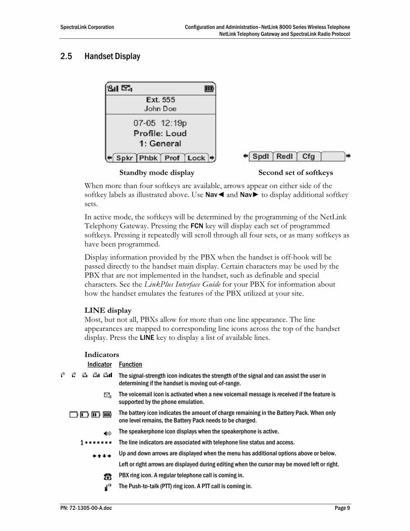
2.5 Handset Display
Standby mode display Second set of softkeys
When more than four softkeys are available, arrows appear on either side of the softkey labels as illustrated above. Use Nav◄ and Nav► to display additional softkey sets.
In active mode, the softkeys will be determined by the programming of the NetLink Telephony Gateway. Pressing the FCN key will display each set of programmed softkeys. Pressing it repeatedly will scroll through all four sets, or as many softkeys as have been programmed.
Display information provided by the PBX when the handset is off-hook will be passed directly to the handset main display. Certain characters may be used by the PBX that are not implemented in the handset, such as definable and special characters. See the LinkPlus Interface Guide for your PBX for information about how the handset emulates the features of the PBX utilized at your site.
LINE display Most, but not all, PBXs allow for more than one line appearance. The line appearances are mapped to corresponding line icons across the top of the handset display. Press the LINE key to display a list of available lines.
Indicators Indicator Function
The signal-strength icon indicates the strength of the signal and can assist the user in determining if the handset is moving out-of-range.
The voicemail icon is activated when a new voicemail message is received if the feature is supported by the phone emulation.
The battery icon indicates the amount of charge remaining in the Battery Pack. When only one level remains, the Battery Pack needs to be charged.
The speakerphone icon displays when the speakerphone is active.
1 ▪ ▪ ▪ ▪ ▪ ▪ ▪ The line indicators are associated with telephone line status and access.
Up and down arrows are displayed when the menu has additional options above or below.
Left or right arrows are displayed during editing when the cursor may be moved left or right.
PBX ring icon. A regular telephone call is coming in.
The Push-to-talk (PTT) ring icon. A PTT call is coming in.
SpectraLink Corporation Configuration and Administration–NetLink 8000 Series Wireless Telephone NetLink Telephony Gateway and SpectraLink Radio Protocol
PN: 72-1305-00-A.doc Page 10
Indicator Function
The priority PTT ring icon. A call is coming in on the priority PTT channel. This call will override any other.
Muted The muted indicator displays after the Mute softkey has been pressed. It indicates that the microphone is not transmitting sound. Press the Mute softkey again to unmute the microphone.
Locked Locked indicates that the keypad is locked to prevent accidental activation. Use the Unlk softkey plus the # key to unlock it.
[No Service message]
If warning tones are not disabled, an alarm will sound and a descriptive message displays when the handset cannot receive or place calls. You may be outside of the covered area. Walk back into the covered area. The in-service tone indicates service is reestablished.
The download icon indicates that the handset is downloading code. This icon only appears while the handset is running the over-the-air downloader. It appears to the right of the Signal Strength icon in the same location as the Voicemail icon.
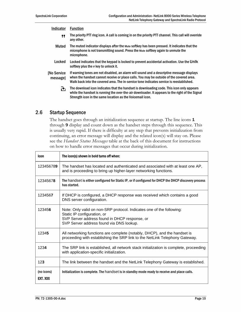
2.6 Startup Sequence The handset goes through an initialization sequence at startup. The line icons 1 through 9 display and count down as the handset steps through this sequence. This is usually very rapid. If there is difficulty at any step that prevents initialization from continuing, an error message will display and the related icon(s) will stay on. Please see the Handset Status Messages table at the back of this document for instructions on how to handle error messages that occur during initialization.
Icon The icon(s) shown in bold turns off when:
123456789 The handset has located and authenticated and associated with at least one AP, and is proceeding to bring up higher-layer networking functions.
12345678 The handset is either configured for Static IP, or if configured for DHCP the DHCP discovery process has started.
1234567 If DHCP is configured, a DHCP response was received which contains a good DNS server configuration.
123456 Note: Only valid on non-SRP protocol. Indicates one of the following: Static IP configuration, or SVP Server address found in DHCP response, or SVP Server address found via DNS lookup.
12345 All networking functions are complete (notably, DHCP), and the handset is proceeding with establishing the SRP link to the NetLink Telephony Gateway.
1234 The SRP link is established, all network stack initialization is complete, proceeding with application-specific initialization.
123 The link between the handset and the NetLink Telephony Gateway is established.
(no icons)
EXT. XXX
Initialization is complete. The handset is in standby mode ready to receive and place calls.

SpectraLink Corporation Configuration and Administration–NetLink 8000 Series Wireless Telephone NetLink Telephony Gateway and SpectraLink Radio Protocol
2.7 Handset Modes
Standby Mode (on-hook) In standby mode, the handset is waiting for an incoming call or for the user to place an outgoing call. The extension number is shown on the display and there is no dial tone. In this mode, the handset is conserving battery power and wireless LAN bandwidth.
When an incoming call occurs, the handset enters a transitional state and will ring until the call is answered by pressing the START key or the END key is pressed to silence the ringing.
Active Mode (off-hook) To place a call, press the START key. This transitions the handset to active off-hook mode. There is a dial tone, the handset is in communication with the PBX, and the display shows information as it is received from the PBX. The user may place a call or press a softkey or the FCN or LINE key to access additional operations.
The handset is also in the active mode when an incoming call is answered.
When an incoming call occurs during an active call the handset will play the second call ringing sound until the call is answered, the caller hangs up, or the call transfers to voicemail. If END is pressed, the first call is terminated and the handset reverts to a full ring.
The active modes utilize the most bandwidth and battery power. To conserve these resources and allow the handset to receive new calls, return the handset to the standby mode when a call is completed by pressing the END key.
Configuration Menu Mode When user preferences are being configured in the Config menu, the handset is on but is not active. It cannot receive calls while in the Config menu.
Push-to-talk (PTT) Mode The NetLink 8030 Wireless Telephone utilizes channels for incoming and outgoing radio communication. While PTT is active, the handset is in PTT mode. It can receive regular phone calls in this mode. When a regular phone call is answered, the handset enters active mode.
Messaging Mode If text messaging functions have been programmed, as in a nurse call system, the handset is able to receive text messages. While these messages are being accessed, the handset is in messaging mode. Incoming calls will ring with the second call ringing sound.
PN: 72-1305-00-A.doc Page 11
SpectraLink Corporation Configuration and Administration–NetLink 8000 Series Wireless Telephone NetLink Telephony Gateway and SpectraLink Radio Protocol
3. NetLink Wireless Telephone Configuration Prior to configuring a NetLink 8000 Series Wireless Telephone, it must be associated with one and only one line on one of the NetLink Telephony Gateways. Then it must be configured per the instructions in this section. The following instructions assume that the handset has been properly associated with a line on a NetLink Telephony Gateway. See NetLink Telephony Gateway: Installation, Configuration, and Administration for additional information. While handsets are being associated, the system will continue normal operation.
Use the Wireless Device Planning Worksheets filled out by the network or system administrator to be sure you are correctly assigning telephone parameters.
The NetLink Handset Administration Tool is a software utility that enables rapid configuration of handsets by utilizing the USB port on the Dual Charger. See the Handset Administration Tool document for specific instructions. Please see your service representative or contact SpectraLink customer service for more information about this time-saving tool.
3.1 The Admin Menu The Admin menu contains configuration options that are stored locally (on each handset). Every handset is independently configured and if the default settings are not desired, the Admin menu options must be set in each handset requiring different settings.
Opening the Admin menu 1. With the handset powered off, press and hold the START key. While holding the
START key, press and release the END key.
2. When the Admin menu appears, release the START key.
If an admin password has been set, the display will require its entry before opening the Admin menu. The default password is 123456. If no password is set, the display will proceed directly into the Admin menu.
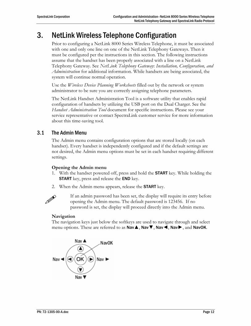
Navigation The navigation keys just below the softkeys are used to navigate through and select menu options. These are referred to as Nav▲, Nav▼, Nav◄, Nav►, and NavOK.
PN: 72-1305-00-A.doc Page 12
SpectraLink Corporation Configuration and Administration–NetLink 8000 Series Wireless Telephone NetLink Telephony Gateway and SpectraLink Radio Protocol
Toggle Options Some menu options that have only two possibilities operate on a toggle basis. The current setting is shown on the second row of the display, called the info line. Press NavOK to toggle between the settings. For example, when Enable PTT is the menu option, PTT Disabled will show on the info line. If you select Enable PTT, PTT Enabled will show on the info line and the menu option will toggle to Disable PTT.
Data Entry and Editing An asterisk (*) next to an option on the display indicates that it is selected. Use the Nav keys and the softkeys to navigate and select desired options.
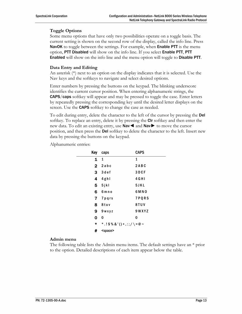
Enter numbers by pressing the buttons on the keypad. The blinking underscore identifies the current cursor position. When entering alphanumeric strings, the CAPS/caps softkey will appear and may be pressed to toggle the case. Enter letters by repeatedly pressing the corresponding key until the desired letter displays on the screen. Use the CAPS softkey to change the case as needed.
To edit during entry, delete the character to the left of the cursor by pressing the Del softkey. To replace an entry, delete it by pressing the Clr softkey and then enter the new data. To edit an existing entry, use Nav◄ and Nav► to move the cursor position, and then press the Del softkey to delete the character to the left. Insert new data by pressing the buttons on the keypad.
Alphanumeric entries:
Key caps CAPS
1 1 1
2 2 a b c 2 A B C
3 3 d e f 3 D E F
4 4 g h I 4 G H I
5 5 j k l 5 J K L
6 6 m n o 6 M N O
7 7 p q r s 7 P Q R S
8 8 t u v 8 T U V
9 9 w x y z 9 W X Y Z
0 0 0
* * . ! $ % & ’ ( ) + , : ; / \ = @ ~
# <space>
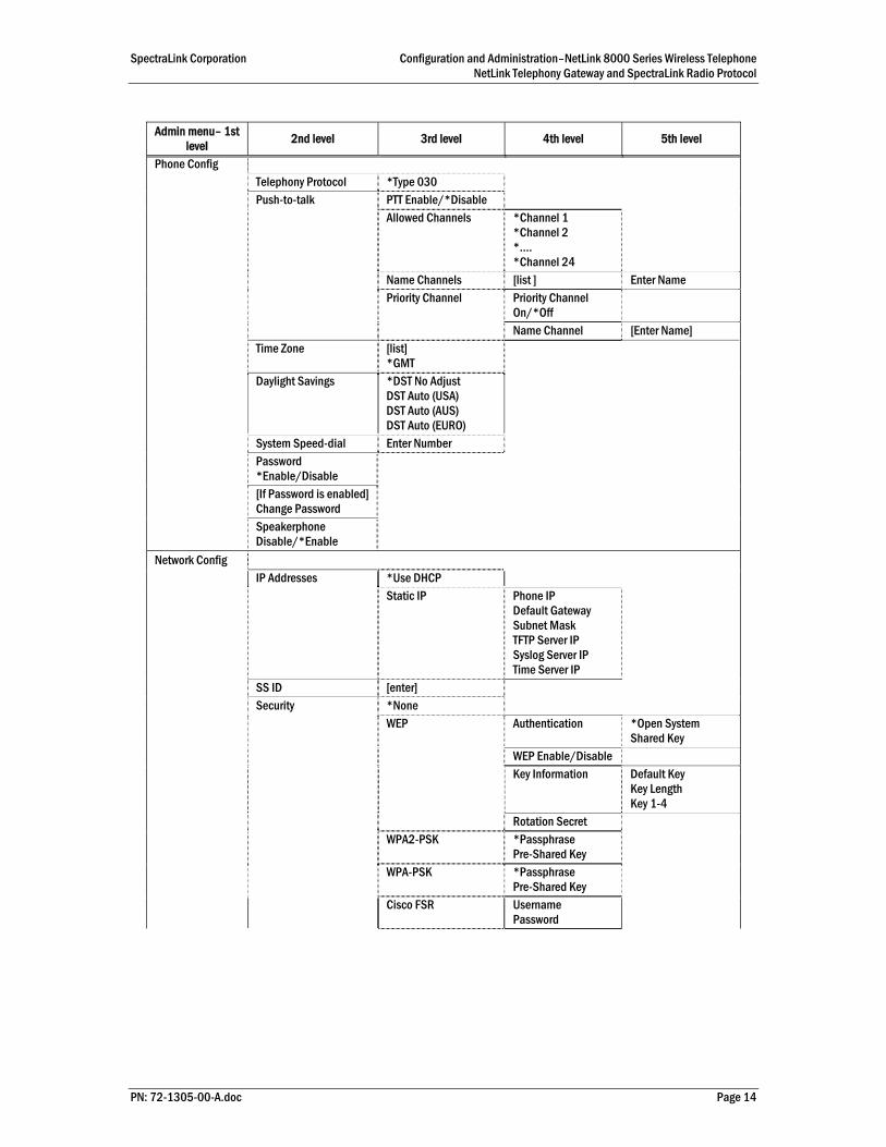
Admin menu The following table lists the Admin menu items. The default settings have an * prior to the option. Detailed descriptions of each item appear below the table.
PN: 72-1305-00-A.doc Page 13
SpectraLink Corporation Configuration and Administration–NetLink 8000 Series Wireless Telephone NetLink Telephony Gateway and SpectraLink Radio Protocol
Admin menu– 1st
level 2nd level 3rd level 4th level 5th level
Phone Config Telephony Protocol *Type 030 Push-to-talk PTT Enable/*Disable Allowed Channels *Channel 1
*Channel 2 *…. *Channel 24
Name Channels [list ] Enter Name Priority Channel Priority Channel
On/*Off
Name Channel [Enter Name] Time Zone [list]
*GMT
Daylight Savings *DST No Adjust DST Auto (USA) DST Auto (AUS) DST Auto (EURO)
System Speed-dial Enter Number Password
*Enable/Disable
[If Password is enabled] Change Password
Speakerphone Disable/*Enable
Network Config IP Addresses *Use DHCP Static IP Phone IP
Default Gateway Subnet Mask TFTP Server IP Syslog Server IP Time Server IP
SS ID [enter] Security *None WEP Authentication *Open System
Shared Key WEP Enable/Disable Key Information Default Key
Key Length Key 1-4
Rotation Secret WPA2-PSK *Passphrase
Pre-Shared Key
WPA-PSK *Passphrase Pre-Shared Key
Cisco FSR Username Password
PN: 72-1305-00-A.doc Page 14
SpectraLink Corporation Configuration and Administration–NetLink 8000 Series Wireless Telephone NetLink Telephony Gateway and SpectraLink Radio Protocol
PN: 72-1305-00-A.doc Page 15
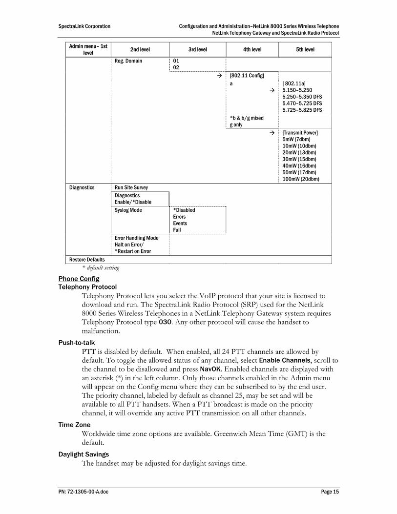
Admin menu– 1st level 2nd level 3rd level 4th level 5th level
Reg. Domain 01 02
[802.11 Config] a
[ 802.11a] 5.150–5.250 5.250–5.350 DFS 5.470–5.725 DFS 5.725–5.825 DFS
*b & b/g mixed g only
[Transmit Power] 5mW (7dbm) 10mW (10dbm) 20mW (13dbm) 30mW (15dbm) 40mW (16dbm) 50mW (17dbm) 100mW (20dbm)
Diagnostics Run Site Survey Diagnostics
Enable/*Disable
Syslog Mode *Disabled Errors Events Full
Error Handling Mode Halt on Error/ *Restart on Error
Restore Defaults * default setting
Phone Config Telephony Protocol
Telephony Protocol lets you select the VoIP protocol that your site is licensed to download and run. The SpectraLink Radio Protocol (SRP) used for the NetLink 8000 Series Wireless Telephones in a NetLink Telephony Gateway system requires Telephony Protocol type 030. Any other protocol will cause the handset to malfunction.
Push-to-talk PTT is disabled by default. When enabled, all 24 PTT channels are allowed by default. To toggle the allowed status of any channel, select Enable Channels, scroll to the channel to be disallowed and press NavOK. Enabled channels are displayed with an asterisk (*) in the left column. Only those channels enabled in the Admin menu will appear on the Config menu where they can be subscribed to by the end user. The priority channel, labeled by default as channel 25, may be set and will be available to all PTT handsets. When a PTT broadcast is made on the priority channel, it will override any active PTT transmission on all other channels.
Time Zone Worldwide time zone options are available. Greenwich Mean Time (GMT) is the default.
Daylight Savings The handset may be adjusted for daylight savings time.

SpectraLink Corporation Configuration and Administration–NetLink 8000 Series Wireless Telephone NetLink Telephony Gateway and SpectraLink Radio Protocol
System Speed-dial The system speed-dial number appears as the first item on the speed-dial list and is specially marked with a greater-than symbol (>) as the first character in its name. It is usually programmed to a number that should be called in emergency situations. Enter the number to be dialed, the name (e.g Security), and scroll to assign to a key press: 1-9, 0, *, #, ^. The carat represents the volume up and down buttons. This number must be programmed in every handset to work system-wide. It cannot be modified by the user.
Password Enable/Disable/Change The password option controls access to the Admin menu. It is enabled by default with the password 123456. The Password option operates as a toggle between Enabled and Disabled. The info line will display the current state. Press NavOK to change the password protection state. To modify the password requirement, the default or previously set password must be entered to verify the change. Change Password will appear only if the password is enabled. The password is disabled by default. The password must be set in each handset for which controlled access is desired.
Speakerphone Enable/Disable The speakerphone may be disabled when quiet handset operation is required. The current speakerphone setting is shown on the info line. Press NavOK to toggle to the alternate setting.
The speakerphone option must be programmed in the NetLink Telephony Gateway for it to function as an off-hook softkey option. See NetLink Telephony Gateway: Installation, Configuration, and Administration for more information. If the speakerphone is disabled in the Admin menu, the Spkr softkey will not appear during standby. However, if it has been programmed in the NetLink Telephony Gateway, the Spkr softkey will appear during active mode but it will be non-functional.
Network Config IP Address
There are two modes in which the handset can operate: DHCP enabled or Static IP. Select the mode for operation from the IP address menu:
* Use DHCP Will use DHCP to assign an IP address each time the handset is turned on. If DHCP is enabled, the handset also receives all other IP address configurations from the DHCP server. Static IP Allows you to manually set a fixed IP address. If selected, the handset will prompt for the IP addresses for each configurable network component. When entering addresses, enter the digits only, including leading zeroes. Do not enter punctuation.
Regardless of the mode in which the handset is operating, the following components must be configured:
PN: 72-1305-00-A.doc Page 16

SpectraLink Corporation Configuration and Administration–NetLink 8000 Series Wireless Telephone NetLink Telephony Gateway and SpectraLink Radio Protocol
Phone IP The IP address of the handset. This is automatically assigned if DHCP is used. If using Static IP configuration, you must obtain a unique IP address for each handset from your network administrator. Default Gateway and Subnet Mask Used to identify subnets, when using a complex network which includes routers. Both of these must be configured either with an IP address under Static IP (not set to 000.000.000.000 or 255.255.255.255) or with DHCP for the handset to contact any network components on a different subnet. If configured on the DHCP server, use option 3 for the Default Gateway and option 1 for the Subnet Mask. Contact your network administrator for the proper settings for your network.
NetLink Wireless Telephones cannot roam with uninterrupted service between subnets unless specific LAN components are present. Certain AP/Ethernet switch combinations establish a layer-2 tunnel across subnets that enables the handsets to roam. Without this capability, any call in progress will be dropped when the user moves out of range and the handset must be power cycled in order to resume functionality in the new subnet area.
Ensure that all your APs are attached to the same subnet for proper operation. The handset can change subnets if DHCP is enabled and the handset is powered off then back on when within range of APs on the new subnet.
Please see Deploying NetLink Wireless Telephones: Best Practices for detailed configuration information.
TFTP Server IP – the IP address of a TFTP server on your network which holds software images for updating the wireless telephones. If this feature is configured (not set to 0.0.0.0 or 255.255.255.255) either via Static IP configuration or using DHCP option 66 (TFTP Server), or the Boot server/next server (siaddr) field, the wireless telephone will check for newer software each time it is powered on or comes back into range of your network. This check takes only a second and ensures that all wireless telephones in your network are kept up-to-date with the same version of software.
Syslog Server IP The IP address of the syslog server. See section 6 Diagnostic Tools for more information. Time Server IP The IP address of the time server.
SSID Enter the SSID.
Security *NONE Disables any 802.11 encryption or security authentication mechanisms.
For WEP, WPA-PSK and WPA2-PSK set each of the following options to match exactly the settings in your APs.
Encryption codes display as they are entered. For security reasons, codes will not display when a user returns to encryption options in the Admin menu.
PN: 72-1305-00-A.doc Page 17
SpectraLink Corporation Configuration and Administration–NetLink 8000 Series Wireless Telephone NetLink Telephony Gateway and SpectraLink Radio Protocol
WEP (Wired Equivalent Privacy) A wireless encryption protocol that encrypts data frames on the wireless medium allowing for greater security in the wireless network. If WEP is required at this site, you must configure each handset to correspond with the encryption protocol set up in the access points. Select the entries from the options below to enable the handset to acquire the system.
Authentication Select either Open System or Shared Key. WEP Enable/Disable Select either Enable WEP or Disable WEP. Key Information
Default Key Enter the key # specified for use by the handsets. This will be 1 through 4. Key Length Select either 40-bit or 128-bit, depending on the key length specified for use at this location. Key 1-4 Scroll to the key option that corresponds to the Default Key that was entered above. Enter the encryption key as a sequence of hexadecimal characters. (Use the 2 and 3 keys to access hexadecimal digits A through F.
Rotation Secret This is used for proprietary WEP key rotation. Refer to your custom document if this feature is supported in your system.
WPA2-PSK The security features of WPA2 using PSK are available and may be used if supported by the access points in the facility. Select either Passphrase and enter a passphrase between 8 and 63 characters in length or Direct Entry and enter the 256-bit key code. WPA-PSK The security features of WPA (Wi-Fi Protected Access) using PSK (pre-shared key) are available and may be used if supported by the access points in the facility. Select either Passphrase and enter a passphrase between 8 and 63 characters in length or Direct Entry and enter the 256-bit key code.
Cisco FSR (Fast Secure Roaming) In order to provide the highest level of security without compromising voice quality on Cisco Aironet wireless LAN APs, SpectraLink and Cisco Systems have cooperated to implement the Fast Secure Roaming mechanism. FSR is designed to minimize call interruptions for NetLink handset users as they roam throughout a facility. Existing Aironet 350, 1100 and 1200 APs may require a firmware upgrade to support FSR. Cisco FSR requires advanced configuration of the Cisco APs in your site. See your Cisco representative for detailed documentation on configuring your APs and other required security services on your wired network. To configure Cisco FSR in your NetLink Wireless Telephone, you must enter a RADIUS server username and password into each handset.
Username Enter a username that matches an entry on your RADIUS server Usernames are alphanumeric strings and can be entered using the alphanumeric string entry technique. Password Enter the password that corresponds to this username.
PN: 72-1305-00-A.doc Page 18
SpectraLink Corporation Configuration and Administration–NetLink 8000 Series Wireless Telephone NetLink Telephony Gateway and SpectraLink Radio Protocol
Consult the Configuration Note for the APs installed in your facility for information on which of the WPA versions are recommended by SpectraLink. Configure the recommended version on the AP and select the corresponding option on the Admin menu.
Regulatory Domain/802.11 Config/Transmit Power
Regulatory domain, 802.11 configuration and transmit power are interdependent settings. Once the domain and 802.11 type are established, the transmit power may be set.
The 802.11 mode and the transmit power level must be set to match the corresponding settings used by the APs in your facility.
FCC requirements dictate that the menu for changing the regulatory domain be available by password, which in our case is the LINE key. To set the domain, press LINE and then select the domain.
01 - North America 02 - Europe
Once the regulatory domain is established, the 802.11 Config modes are displayed. Only one may be chosen. 802.11(b & b/g mixed) is the default. If 802.11(a) is selected, another menu opens so that you can select 802.11a transmission frequency range(s). Only those ranges which are allowed in the selected domain are displayed. Multiple ranges may be selected. Selected mode and ranges are marked with an asterisk (*). Press the Done softkey when you are finished specifying the 802.11 mode. The Transmit Power menu opens when the Done softkey is pressed. Only those power levels which apply to the domain and 802.11 mode are listed. Only one level may be selected. The default will vary with the domain and 802.11 mode. The selected level is marked with an asterisk (*). Note that the bands labeled DFS may vary depending on the selected regulatory domain.
Diagnostics Run Site Survey
The Site Survey mode is activated by selecting this option. A site survey starts running immediately upon selecting this option. See the Diagnostic Tools section for more information about site surveys.
Diagnostics Mode See section 6.2 Diagnostics Mode for a detailed explanation of the Diagnostics Mode options.
Syslog Mode See section 6.3 Syslog Mode for a detailed explanation of the syslog mode options.
Error Handling Mode The error handling mode determines how the handset will behave when an error occurs. The Halt on Error option will cause the handset to stop operating if an error message is received. Unless the error is a fatal one, normal operation may be resumed by power-cycling the handset. The Restart on Error option will cause the
PN: 72-1305-00-A.doc Page 19
SpectraLink Corporation Configuration and Administration–NetLink 8000 Series Wireless Telephone NetLink Telephony Gateway and SpectraLink Radio Protocol
handset to make every effort to reboot quietly and quickly to standby mode. In either scenario, a call in progress will be lost.
Error detail may be shown on the display, captured by the syslog server and may also be available for downloading with the Handset Administration Tool.
Restore Defaults The Restore Defaults option will set all user and administrative parameters except Telephony Protocol to their factory defaults.
PN: 72-1305-00-A.doc Page 20
SpectraLink Corporation Configuration and Administration–NetLink 8000 Series Wireless Telephone NetLink Telephony Gateway and SpectraLink Radio Protocol
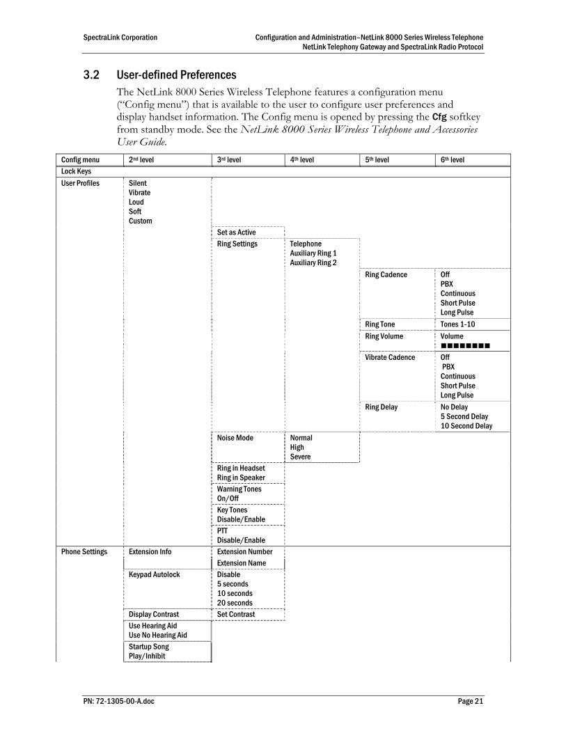
3.2 User-defined Preferences The NetLink 8000 Series Wireless Telephone features a configuration menu (“Config menu”) that is available to the user to configure user preferences and display handset information. The Config menu is opened by pressing the Cfg softkey from standby mode. See the NetLink 8000 Series Wireless Telephone and Accessories User Guide.
Config menu 2nd level 3rd level 4th level 5th level 6th level Lock Keys User Profiles Silent
Vibrate Loud Soft Custom
Set as Active Ring Settings Telephone
Auxiliary Ring 1 Auxiliary Ring 2
Ring Cadence Off PBX Continuous Short Pulse Long Pulse
Ring Tone Tones 1-10 Ring Volume Volume
Vibrate Cadence Off
PBX Continuous Short Pulse Long Pulse
Ring Delay No Delay 5 Second Delay 10 Second Delay
Noise Mode Normal High Severe
Ring in Headset Ring in Speaker
Warning Tones On/Off
Key Tones Disable/Enable
PTT Disable/Enable
Phone Settings Extension Info Extension Number Extension Name Keypad Autolock Disable
5 seconds 10 seconds 20 seconds
Display Contrast Set Contrast Use Hearing Aid
Use No Hearing Aid
Startup Song Play/Inhibit
PN: 72-1305-00-A.doc Page 21
SpectraLink Corporation Configuration and Administration–NetLink 8000 Series Wireless Telephone NetLink Telephony Gateway and SpectraLink Radio Protocol
PN: 72-1305-00-A.doc Page 22
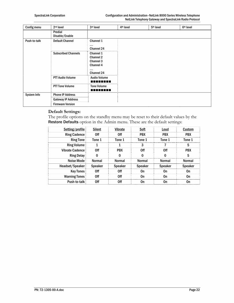
Config menu 2nd level 3rd level 4th level 5th level 6th level Predial
Disable/Enable
Push-to-talk Default Channel Channel 1 …. Channel 24
Subscribed Channels Channel 1 Channel 2 Channel 3 Channel 4 …. Channel 24
PTT Audio Volume Audio Volume
PTT Tone Volume Tone Volume
System Info Phone IP Address Gateway IP Address Firmware Version
Default Settings: The profile options on the standby menu may be reset to their default values by the Restore Defaults option in the Admin menu. These are the default settings:
Setting/profile Silent Vibrate Soft Loud Custom
Ring Cadence Off Off PBX PBX PBX Ring Tone Tone 1 Tone 1 Tone 1 Tone 1 Tone 1
Ring Volume 1 1 3 7 5 Vibrate Cadence Off PBX Off Off PBX
Ring Delay 0 0 0 0 5 Noise Mode Normal Normal Normal Normal Normal
Headset/Speaker Speaker Speaker Speaker Speaker Speaker Key Tones Off Off On On On
Warning Tones Off Off On On On Push-to-talk Off Off On On On
SpectraLink Corporation Configuration and Administration–NetLink 8000 Series Wireless Telephone NetLink Telephony Gateway and SpectraLink Radio Protocol
4. Software License and Protocol Management The NetLink Wireless Telephone System supports a number of different IP protocol integrations. All NetLink 8000 Series Wireless Telephones are shipped from SpectraLink with a generic software load that allows them to associate to a wireless LAN and download their functional software from a TFTP server. The handsets may not function properly without downloading appropriate software.
The following details the process to properly configure handsets and download software via over-the-air file transfer.
4.1 Requirements • A wireless LAN must be properly configured and operational through the use of
802.11a/b/g wireless APs.
• The NetLink Telephony Gateway must also be connected to your network and completely operational, and the handset must be registered to it.
• The NetLink Telephony Gateways have a TFTP server and must be available on the network in order to load the appropriate software into the handsets. Most installations choose to take advantage of the TFTP server that accompanies the NetLink Telephony Gateway, making a separate TFTP server unnecessary.
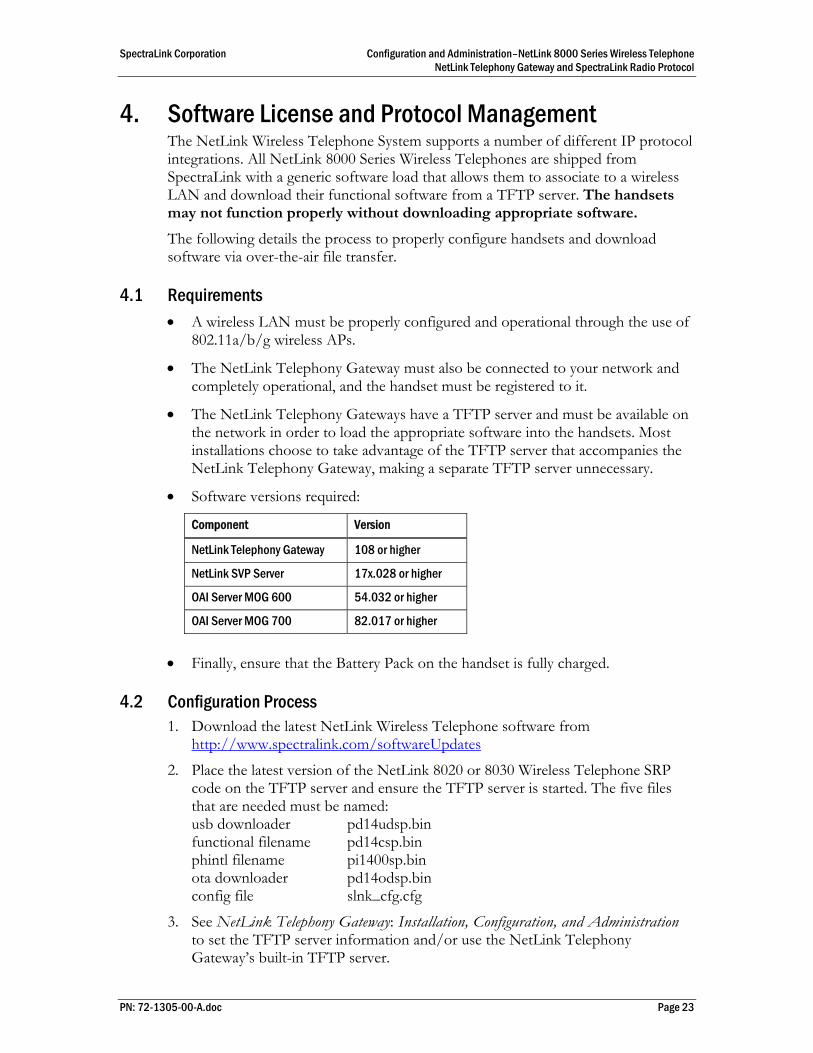
• Software versions required:
Component Version
NetLink Telephony Gateway 108 or higher
NetLink SVP Server 17x.028 or higher
OAI Server MOG 600 54.032 or higher
OAI Server MOG 700 82.017 or higher
• Finally, ensure that the Battery Pack on the handset is fully charged.
4.2 Configuration Process 1. Download the latest NetLink Wireless Telephone software from
http://www.spectralink.com/softwareUpdates
2. Place the latest version of the NetLink 8020 or 8030 Wireless Telephone SRP code on the TFTP server and ensure the TFTP server is started. The five files that are needed must be named: usb downloader pd14udsp.bin functional filename pd14csp.bin phintl filename pi1400sp.bin ota downloader pd14odsp.bin config file slnk_cfg.cfg
3. See NetLink Telephony Gateway: Installation, Configuration, and Administration to set the TFTP server information and/or use the NetLink Telephony Gateway’s built-in TFTP server.
PN: 72-1305-00-A.doc Page 23

SpectraLink Corporation Configuration and Administration–NetLink 8000 Series Wireless Telephone NetLink Telephony Gateway and SpectraLink Radio Protocol
4. Use the Handset Administration Tool to set up the configuration of each handset to meet all essential requirements. If not using the Handset Administration Tool, ensure the following parameters are correctly set in the Admin menu for each handset: See section 3 NetLink Wireless Telephone Configuration for detailed configuration instructions.
• If statically assigning IP addresses, ensure that the Phone IP, Subnet Mask, and Default Gateway information are accurate. If using a DHCP Server, ensure that the DHCP option is set.
• Ensure the handset has properly configured SSID and Reg Domain information.
• Ensure the Telephony Protocol menu option is set to 030. This ensures the handset will check for the proper SRP files each time it powers on.
• Ensure security settings are properly programmed.
5. Power cycle the handset.
6. The SRP code will now download to the handset. The status bar will increment fully across the display for each function that is being performed in the download process and the filename will display. Upon completion of the update process, the handset will re-boot with the new firmware.
For future software upgrades, simply update the files that are stored on the TFTP server. Each time the handset is powered up, it will check with the TFTP server to ensure it has the proper software version.
PN: 72-1305-00-A.doc Page 24
SpectraLink Corporation Configuration and Administration–NetLink 8000 Series Wireless Telephone NetLink Telephony Gateway and SpectraLink Radio Protocol
5. Testing the Handsets Verify proper registration and operation of each handset by performing the following tests on the handset in an active wireless area. 1. Power on the handset by pressing END. You will see a series of messages
displayed as the handset acquires the system. The handset should display the user extension or dashes if no extension is programmed. Any error messages should clear.
2. Press the START key. The extension number should clear and you should hear dial tone. On some digital systems, depending on how the telephone system is programmed, you may have to select a line to get dial tone. Place a call and listen to the audio quality. End the call by pressing the END key.
3. Place a call to the handset and verify ring, answer, clear transmit and clear receive audio.
4. Use the softkeys to verify all softkey programmed features on the handset. 5. Press the END key. Any line indicators should turn off and the extension number
display will return.
If any of these steps fails to operate as described, refer to section 9 Troubleshooting for corrective action.
PN: 72-1305-00-A.doc Page 25
SpectraLink Corporation Configuration and Administration–NetLink 8000 Series Wireless Telephone NetLink Telephony Gateway and SpectraLink Radio Protocol
6. Diagnostic Tools Run Site Survey, Diagnostics Enabled and Syslog Mode are three diagnostic tools provided to assist the wireless LAN administrator in evaluating the functioning of the NetLink 8000 Series handset and the system surrounding it. Diagnostic Tools are enabled in the Admin menu.
6.1 Run Site Survey Site survey is used to evaluate the facility coverage before certifying that an installation is complete. It can also be used at any time to evaluate coverage by testing signal strength, to gain information about an AP, and to scan an area to look for all APs regardless of SSID. The information available through the site survey includes:
• SSID • Beacon Interval • Information regarding support of 802.11d, 802.11g, 802.11h and other
802.11 amendment standards as required • Current security configuration
Start the site survey by selecting Run Site Survey from the Admin menu. The mode starts immediately. When the test is started, it is by default in “single SSID” mode. When the Any soft key is pressed (softkey A) all APs, regardless of SSID, are displayed and the softkey changes to say MyID. Pressing the MyID soft key will revert to the “single SSID” mode and change the softkey back to Any.
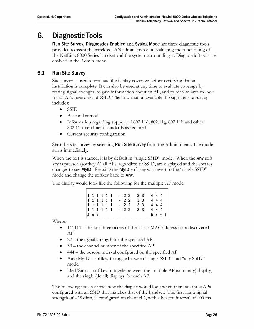
The display would look like the following for the multiple AP mode.
1 1 1 1 1 1 - 2 2 3 3 4 4 4 1 1 1 1 1 1 - 2 2 3 3 4 4 4 1 1 1 1 1 1 - 2 2 3 3 4 4 4 1 1 1 1 1 1 - 2 2 3 3 4 4 4 A n y D e t l
Where: • 111111 – the last three octets of the on-air MAC address for a discovered
AP. • 22 – the signal strength for the specified AP. • 33 – the channel number of the specified AP. • 444 – the beacon interval configured on the specified AP. • Any/MyID – softkey to toggle between “single SSID” and “any SSID”
mode. • Detl/Smry – softkey to toggle between the multiple AP (summary) display,
and the single (detail) displays for each AP.
The following screen shows how the display would look when there are three APs configured with an SSID that matches that of the handset. The first has a signal strength of –28 dbm, is configured on channel 2, with a beacon interval of 100 ms.
PN: 72-1305-00-A.doc Page 26

SpectraLink Corporation Configuration and Administration–NetLink 8000 Series Wireless Telephone NetLink Telephony Gateway and SpectraLink Radio Protocol
The second has a signal strength of –48 dbm, is configured on channel 6, with a beacon interval of 200 ms. The third has a signal strength of –56 dbm, is configured on channel 11 with a beacon interval of 100 ms.
a b 7 b c 8 - 2 8 0 2 1 0 0 2 a e 5 7 8 - 4 8 0 6 2 0 0 2 a e 5 9 6 - 5 6 1 1 1 0 0
A n y D e t l
When the Any SSID mode is selected, the summary display contains the first six characters of the APs SSID instead of the beacon interval as in the example below.
a b 7 b - 2 8 0 2 A L P H A 2 a e 5 - 4 8 0 6 W S M T E S 2 a e 5 - 5 6 1 1 v o i c e
M y I D D e t l
In detail mode the display would appear as follows. The left/right arrow keys will move between AP indices.
i : b b b b b b s n c h b c n e e e e e e e e e e e D G H I r r r r r r r r r r r r r + x x x x m m m G : g g g g P : p p p p A n y S m r y
Where: • i – index of selected AP (value will be from 0 to 3 inclusive) • bbbbbb – the last three octets of the BSSID for a discovered AP • sn – signal strength in –dbm • ch – channel • bcn – beacon interval • eeeeeeeeeee – SSID (up to first 11 characters) • DGHI – standards supported • rrrrrrrr – rates supported. Basic rates will have a “b” following the rate • + – more rates are supported than those displayed • xxxx – WMM or UPSD if those QoS methods are supported • mmm – security mode • G:gggg – group key security • P:pppp – pairwise key security • Any/MyID – softkey to toggle between “single SSID” and “any SSID”
modes • Detl/Smry – softkey to toggle between the multiple AP display (summary),
and the single AP display (detail)
Numbers racing across the handset display indicate AP information is being obtained. A Waiting message indicates the system is not configured properly and the handset cannot find any APs.
PN: 72-1305-00-A.doc Page 27

SpectraLink Corporation Configuration and Administration–NetLink 8000 Series Wireless Telephone NetLink Telephony Gateway and SpectraLink Radio Protocol
Solving Coverage Issues Coverage issues are best resolved by adding and/or relocating APs.
Overlap issues may be resolved by reassigning channels to the APs or by relocating them. See the Troubleshooting section Access Point Problems for more information.
6.2 Diagnostics Enabled Diagnostics is used to evaluate the overall quality of the link between the handset, AP, and infrastructure side equipment, such as IP PBX, NetLink SVP Server, and gateways. Unlike Site Survey, Diagnostics is used while the functional code is running, and during a call. When Diagnostics is enabled in the Admin menu, the handset can display diagnostic screens any time it is in active mode. The display of information is instigated by pressing the Nav◄ or Nav► key. Only four of the diagnostic counters listed below can be shown at a time. Pressing the Nav keys multiple times will cycle through the various counters and the normal off-hook (IP-PBX) display. The numeric icon at the top of the display indicates what screen number is being displayed. For example: The first time the Nav key is pressed, the 1 icon is shown, and the first four counters are displayed. The next time it is pressed, the 2 icon is shown, and the next four counters are displayed. The counters will be cycled through in this fashion until there are no more counters to be displayed. After all the counters have been displayed, the screen returns to the normal off-hook IP-PBX screen.
The information provided by Diagnostics includes:
Screen 1 • Missed receive packet count since power up (MissedRcvCnt) • Missed transmit packet count since power up (MissedXmtCnt) • Receive retry count since power up (RxRetryCount) • Transmit retry count since power up (TxRetryCount)
M i s s e d R c v C n t n n n n n M i s s e d X m t C n t n n n n n R x R e t r y C o u n t n n n n n T x R e t r y C o u n t n n n n n
PN: 72-1305-00-A.doc Page 28

SpectraLink Corporation Configuration and Administration–NetLink 8000 Series Wireless Telephone NetLink Telephony Gateway and SpectraLink Radio Protocol
Screen 2 • Jitter – average error or “wobble” in received packet timing, in microseconds • Last successful transmit data rate (LastRate) • Gateway type (GatewyType)
J i t t e r n n n n n L a s t R a t e n n n n n G a t e w y T y p e m n e m o
Where: mnemo – a mnemonic that indicates what type of gateway is being used
• 11Mb – this system can run at full speed
Screen 3 Screen 3 contains a list of the APs that are heard and the following parameters from each AP:
• Indicator as to whether this is the current AP or an index into the list of other APs heard (C indicates current)
• Last 2 octets of the MAC address of the AP (mmmm) • Channel number (ch) • Signal strength (ss) • Either the 802.11 Association ID from the current AP or a mnemonic for
the reason code indicating why the handset didn’t hand off to this other AP
C : m m m m c h - s s a i d 1 : m m m m c h - s s m n e m 2 : m m m m c h - s s m n e m 3 : m m m m c h - s s m n e m
Where: AP mnem – a mnemonic indicating the reason code:
• Unkn – reason unknown • Weak – signal strength too weak • Rate – one or more basic rates not supported • Full – AP can not handle bandwidth requirements • AthT – authentication timeout • AscT – association timeout • AthF – authentication failure • AscF – association failure • SecT – security handshake timeout • SecF – security handshake failure • Cnfg – AP not configured correctly for security, QoS mode or infrastructure
network
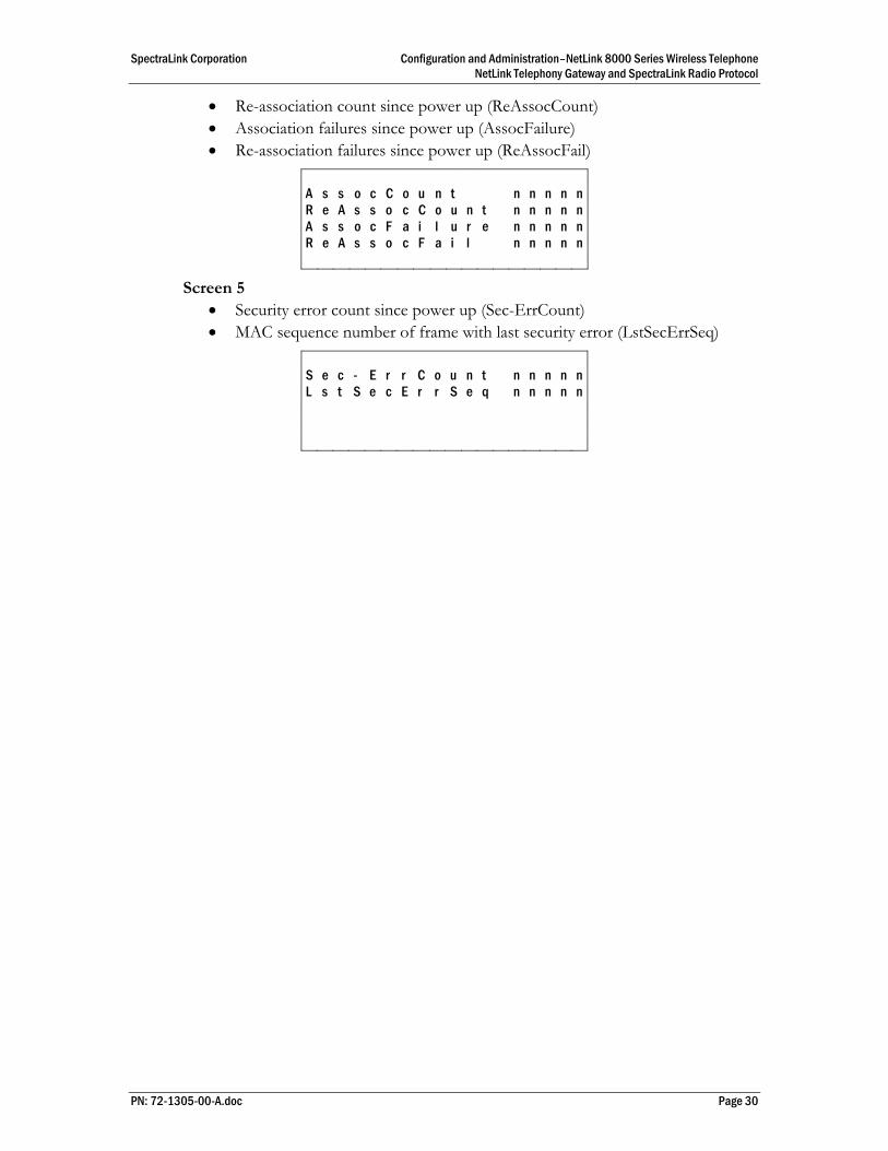
Screen 4 • Association count since power up (AssocCount)
PN: 72-1305-00-A.doc Page 29
SpectraLink Corporation Configuration and Administration–NetLink 8000 Series Wireless Telephone NetLink Telephony Gateway and SpectraLink Radio Protocol
• Re-association count since power up (ReAssocCount) • Association failures since power up (AssocFailure) • Re-association failures since power up (ReAssocFail)
A s s o c C o u n t n n n n n R e A s s o c C o u n t n n n n n A s s o c F a i l u r e n n n n n R e A s s o c F a i l n n n n n
Screen 5 • Security error count since power up (Sec-ErrCount) • MAC sequence number of frame with last security error (LstSecErrSeq)
S e c - E r r C o u n t n n n n n L s t S e c E r r S e q n n n n n
PN: 72-1305-00-A.doc Page 30
SpectraLink Corporation Configuration and Administration–NetLink 8000 Series Wireless Telephone NetLink Telephony Gateway and SpectraLink Radio Protocol
6.3 Syslog Mode A syslog server must be present on the network in order for the handset to send the log messages and have them saved. The syslog server will be found with DHCP option 7 if the handset is using DHCP. If static addresses are configured, the syslog server’s IP address can be configured statically in the Admin menu.
If the syslog server address is blank (000.000.000.000 or 255.255.255.255) or the handset is using DHCP and no option 7 is received from the DHCP server, the handset will not send any syslog messages.
Admin menu options: • *Disabled – turns syslog off • Errors – causes the handset to log only events that we consider to be an error
(see below) • Events – logs all errors plus some other interesting events (see below). • Full – logs all the above plus a running stream of other quality information
(see below)
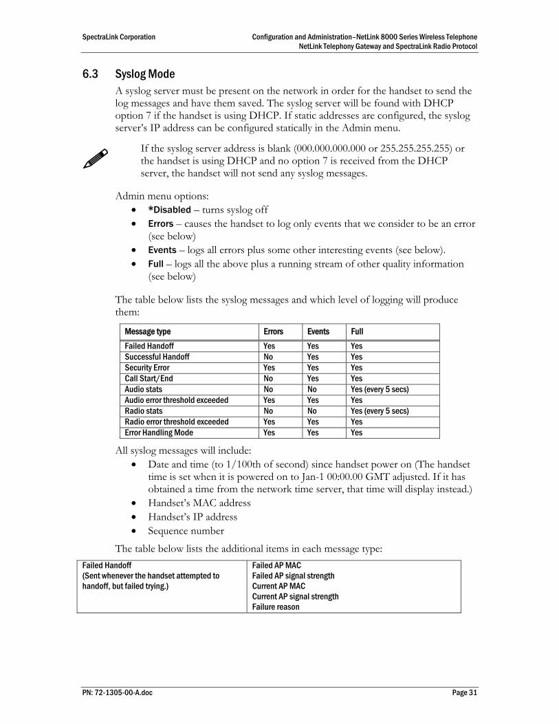
The table below lists the syslog messages and which level of logging will produce them:
Message type Errors Events Full Failed Handoff Yes Yes Yes Successful Handoff No Yes Yes Security Error Yes Yes Yes Call Start/End No Yes Yes Audio stats No No Yes (every 5 secs) Audio error threshold exceeded Yes Yes Yes Radio stats No No Yes (every 5 secs) Radio error threshold exceeded Yes Yes Yes Error Handling Mode Yes Yes Yes
All syslog messages will include: • Date and time (to 1/100th of second) since handset power on (The handset
time is set when it is powered on to Jan-1 00:00.00 GMT adjusted. If it has obtained a time from the network time server, that time will display instead.)
• Handset’s MAC address • Handset’s IP address • Sequence number
The table below lists the additional items in each message type: Failed Handoff (Sent whenever the handset attempted to handoff, but failed trying.)
Failed AP MAC Failed AP signal strength Current AP MAC Current AP signal strength Failure reason
PN: 72-1305-00-A.doc Page 31

SpectraLink Corporation Configuration and Administration–NetLink 8000 Series Wireless Telephone NetLink Telephony Gateway and SpectraLink Radio Protocol
Successful Handoff New AP MAC New AP signal strength Old AP MAC Old AP signal strength Reason for handoff Other candidate APs: MAC Signal strength Reason not used
Security Error AP MAC AP signal strength Security mode Error details (mode-dependent)
Call Start Call type (telephony, OAI, PTT) AP MAC AP signal strength
Call End AP MAC AP signal strength
Audio stats AP MAC AP signal strength Payload size (in msec) Payloads sent Payloads received Payloads missed (not received) Payloads missed rate (over last 5 seconds) Payloads late Payloads late rate (over last 5 seconds) Average jitter
Audio error threshold exceeded (Sent if payloads missed rate or payloads late rate exceeds 2%, or if the average jitter is over 2 msec)
Same as audio stats
Radio stats AP MAC AP signal strength Directed packets sent Directed packets received Multicast packets sent Multicast packets received Broadcast packets sent Broadcast packets received TX dropped count TX drop rate (over last 5 seconds) TX retry count TX retry rate (over last 5 seconds) RX retry count RX retry rate (over last 5 seconds)
Radio error threshold exceeded (Sent if TX drop rate exceeds 2% or TX or RX retry rate exceeds 5%)
Same as radio stats
Messages are formatted like the following example: Jan 1 00:01:26.72 0090.7a02.2a1b (172.16.0.46) [001a] RStat: AP 00:40:96:48:1D:0C (-56 dBm), Sent 783523, Recvd 791342, MSnt 245, MRcd 5674, BSnt 43, BRcd 10783, TX drop 43 (0.0%), TX retry 578 (1.2%), RX retry 1217 (1.6%)
PN: 72-1305-00-A.doc Page 32
SpectraLink Corporation Configuration and Administration–NetLink 8000 Series Wireless Telephone NetLink Telephony Gateway and SpectraLink Radio Protocol
7. Certifying the Handsets Prior to determining that an installation is complete, test the handsets following the sequence given in section 5 Testing a Handset and conduct a site survey mode test according to the directions given in section 6 Diagnostic Tools. The installation may need some adjustments. Note any areas where coverage is conflicting or inadequate. Note any system difficulties and work with your wireless LAN and/or LAN system administrator to determine the cause and possible remedy. See section 9 Troubleshooting for clues to possible sources of difficulties. If any adjustments are made to the system, re-test the device in the same vicinity to determine if the difficulty is resolved.
These tests must be performed in typical operating conditions, especially if heavy loads occur. Testing sequence and procedure is different for every installation. Generally, you should organize the test according to area and volume, placing numerous calls to others who can listen while you perform coverage tests. Note any areas with excessive static or clarity problems and report it to a SpectraLink service engineer. The coverage test will also require you to put the handset in Site Survey mode and walk the entire coverage area to verify all APs.
7.1 Conducting a Site Survey Conduct a site survey of the installation by walking the site looking for interfering 802.11 systems, adequate coverage and channel assignment and correct AP configuration. 1. Referring to section 6.1 Run Site Survey, put a handset into site survey in the Any
SSID mode, Smry display. Walk throughout the site checking for any expected APs or other SSIDs.
2. Then walk the site again in MyID SSID mode, Smry display. This time check that every location has adequate coverage (there should be at one AP stronger than -70dBm in all areas) and has good channel allocation (at any point, the strongest AP shown should be on a different channel than the next best choice).
3. Finally, use the single AP (MyID) and Detl display to check each AP to ensure it is configured for the proper data rates, beacon interval, 802.11 options enabled, QoS method and security method.
4. Make any necessary adjustments to AP locations and configurations and repeat steps 1 through 3 until the site survey shows adequate coverage and correct configuration at every location.
The installation is not complete until these certification steps have been performed. Do not hand out wireless telephones at a site that has not been certified.
PN: 72-1305-00-A.doc Page 33
SpectraLink Corporation Configuration and Administration–NetLink 8000 Series Wireless Telephone NetLink Telephony Gateway and SpectraLink Radio Protocol
8. Software Maintenance The NetLink 8000 Series Wireless Telephones use proprietary software programs written and maintained by SpectraLink Corporation. The software versions that are running on the handsets can be displayed during power on by holding down the END button. Firmware Version is also an option on the Config menu.
SpectraLink Customer Service or an authorized dealer will provide information about software updates and how to obtain the software (for example, downloading updates from a website).
Upgrading Handsets After software updates are obtained from SpectraLink, they must be transferred to the NetLink Telephony Gateway or other TFTP server. See NetLink Telephony Gateway: Installation, Configuration, and Administration for an explanation of how to update the NetLink Wireless Telephone software in the NetLink Telephony Gateway so that it can then be downloaded into the handsets.
NetLink Wireless Telephones allow over-the-air transfer of software updates from the NetLink Telephony Gateway to the handsets. The download function in the handset checks its software version every time the handset is turned on. If there is any discrepancy the handset immediately begins to download the update.
Normal Download Messages When the handset is powered on, it displays a series of messages indicating that it is searching for new software, checking the versions, and downloading. The normal message progression is:
Message Description
Checking Code Handset is contacting the TFTP server to determine if it has a newer version of software that should be downloaded.
Erasing Memory Handset has determined that a download should occur and is erasing the current software from memory. This message also displays a progress bar. When the progress bar fills the display line the erase operation is complete.
Updating Code Handset is downloading new software into memory. The number icons at the bottom of the display indicate which file number is currently being downloaded. This message also displays a progress bar. When the progress bar fills the display line the update operation is complete on that file.
When the update is complete, the handset displays the extension number and is ready for use.
Download Failure or Recovery Messages The following display messages indicate a failure or recovery situation during the download process. See section 9 Troubleshooting for more information about each message.
Server Busy TFTP ERROR(x):yy Erase Failed Waiting Internal Errors
PN: 72-1305-00-A.doc Page 34

SpectraLink Corporation Configuration and Administration–NetLink 8000 Series Wireless Telephone NetLink Telephony Gateway and SpectraLink Radio Protocol
9. Troubleshooting On occasion, you may run into transmission problems due to any number of factors originating from the wireless LAN. NetLink 8000 Series Wireless Telephones can exhibit transmission problems in several ways. They can cease functioning properly, display error messages or display incorrect data. When using and troubleshooting handsets, consider the following problem sources to determine the best method of approaching any specific situation.
9.1 Access Point Problems Most, but not all, handset audio problems have to do with AP range, positioning and capacity. Performing a site survey as described above can isolate the AP causing these types of problems. If the handset itself is suspected, conduct a parallel site survey with a handset that is known to be properly functioning.
In-range/Out-of-range Service will be disrupted if a user moves outside the area covered by the APs. Service is restored if the user moves back within range. If a call drops because a user moves out–of-range, the handset will recover the call if the user moves back into range within a few seconds.
Capacity In areas of heavy use, the call capacity of a particular access point may be filled. If this happens, the user will hear three chirps from the handset. The user can wait until another user terminates a call, or move within range of another AP and try the call again. If a user is on a call and moves into an area where capacity is full, the system attempts to find another access point. Due to range limitations, this may be the same as moving out of range.
Transmission Obstructions Prior to system installation, the best location for APs for optimum transmission coverage was determined. However, small pockets of obstruction may still be present or obstructions may be introduced into the facility after system installation. This loss of service can be restored by moving out of the obstructed area or by adding APs.
9.2 Configuration Problems Certain problems are associated with improper configuration of the NetLink Telephony Gateway, the NetLink Wireless Telephone or the NetLink SVP Server.
For instance, no extension displayed or wrong extension displayed on the handset has no effect on its operation but serves to easily identify it. Other configuration problems, like having incorrect menu items, or inability to connect or access telephone system features, affect the handset’s functioning.
Configuration problems are generally corrected by changing the configuration at the NetLink Telephony Gateway, the NetLink SVP Server or on the handset. See the NetLink Telephony Gateway: Installation, Configuration, and Administration document for specific configuration steps. There may also be incorrect programming
PN: 72-1305-00-A.doc Page 35
SpectraLink Corporation Configuration and Administration–NetLink 8000 Series Wireless Telephone NetLink Telephony Gateway and SpectraLink Radio Protocol
of the PBX or AP. See the appropriate LinkPlus Integration Guide or the Configuration Note for the AP in use at the site.
9.3 Infrastructure Problems Calls ringing on the wrong handset or when multiple handsets are not working often indicate faulty installation. The wires that connect the demarcation (demarc) block to the NetLink Telephony Gateway may be installed incorrectly.
Contact your wireless LAN and/or PBX vendor for more information about troubleshooting infrastructure problems.
9.4 Dial tone Problems A dial tone problem exists if the handset has no dial tone or if the user is unable to hear the other party’s voice, hears echo or hears dead air. Dial tone problems can be caused by a number of different situations and should be investigated by following these steps:
1. Power on the handset in an active service area. If the handset does not get a dial tone in an active area, continue with the steps below. If the no dial tone problem is limited to a certain area, see section 9.1 Access Point Problems. Any initialization or error messages should turn off a few seconds after the handset is powered on.
2. Swap the Battery Pack with a Battery Pack from a functional handset, power the handset back on and check for dial tone. If this corrects the problem, try recharging the Battery Pack that was removed.
3. Turn the handset off, then on again, and then test again for dial tone. If functioning, place a call and determine voice quality.
4. While maintaining an active call, walk through several AP areas. If fluctuation occurs see section 9.1 Access Point Problems.
5. Check for alarms on the NetLink Telephony Gateway or the NetLink SVP Server (via System Status). If there are alarms, see NetLink Telephony Gateway: Installation, Configuration, and Administration or NetLink SVP Server: Installation, Configuration, and Administration for information.
6. Make sure the handset’s gateway port is connected to a working telephone line. Check the line at the demarc block. You may need to contact your vendor to perform this check.
7. Check the cabling between the gateway and the demarc block and between the demarc block and the telephone system ports.
8. Move the handset to a different port location and test again.
PN: 72-1305-00-A.doc Page 36
SpectraLink Corporation Configuration and Administration–NetLink 8000 Series Wireless Telephone NetLink Telephony Gateway and SpectraLink Radio Protocol
9.5 Handset Status Messages Handset status messages provide information about the NetLink 8000 Series Wireless Telephone’s communication with the AP and host telephone system. The following table summarizes the status messages, in alphabetical order.
Message Description Action
3 chirps (audio) Handset is not able to communicate with the best AP, probably because that AP has no bandwidth available.
None. This is only a warning, the call will handoff to the best AP once it becomes available.
Address Mismatch Handset software download files are incorrect or corrupted.
Download new software from the SpectraLink site per section 8 Software Maintenance.
Assoc Failed xxxxxxxxxxxx
x…x = AP MAC address. Handset association was refused by AP; displays MAC of failing AP.
Check handset and AP security settings. Ensure AP is configured per Configuration Note. Try another AP.
Assoc Timeout xxxxxxxxxxxx
x…x = AP MAC address. Handset did not receive association response from AP; displays MAC of failing AP.
Check handset and AP security settings. Ensure AP is configured per Configuration Note. Try another AP.
Auth Failed xxxxxxxxxxxx
x…x = AP MAC address. Handset authentication was refused by AP; displays MAC of failing AP.
Check handset and AP security settings. Ensure AP is configured per Configuration Note. Try another AP.
Auth Timeout xxxxxxxxxxxx
x…x = AP MAC address. Handset did not receive authentication response from AP; displays MAC of failing AP.
Check handset and AP security settings. Ensure AP is configured per Configuration Note. Try another AP.
Bad Code Type xx Expected Code Type yy
xx, yy = software license types Handset software does not match current handset license selection.
Download new software from the SpectraLink site per section 8 Software Maintenance.
Bad Config Some needed configuration type has not been set.
Check all required handset configuration parameters for valid settings.
Bad SSID No SSID has been entered. Enter an SSID in the Admin menu.
Bad Phintl File Handset software download files are incorrect or corrupted.
Download new software from the SpectraLink site per section 8 Software Maintenance.
Bad Program File Handset software download files are incorrect or corrupted.
Download new software from the SpectraLink site per section 8 Software Maintenance.
PN: 72-1305-00-A.doc Page 37
SpectraLink Corporation Configuration and Administration–NetLink 8000 Series Wireless Telephone NetLink Telephony Gateway and SpectraLink Radio Protocol
PN: 72-1305-00-A.doc Page 38
Message Description Action
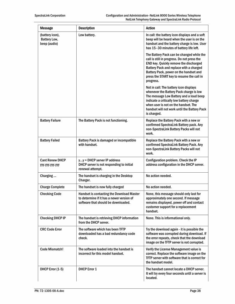
(battery icon), Battery Low, beep (audio)
Low battery. In call: the battery icon displays and a soft beep will be heard when the user is on the handset and the battery charge is low. User has 15–30 minutes of battery life left.
The Battery Pack can be changed while the call is still in progress. Do not press the END key. Quickly remove the discharged Battery Pack and replace with a charged Battery Pack, power on the handset and press the START key to resume the call in progress.
Not in call: The battery icon displays whenever the Battery Pack charge is low The message Low Battery and a loud beep indicate a critically low battery charge when user is not on the handset. The handset will not work until the Battery Pack is charged.
Battery Failure The Battery Pack is not functioning. Replace the Battery Pack with a new or confirmed SpectraLink Battery pack. Any non-SpectraLink Battery Packs will not work.
Battery Failed Battery Pack is damaged or incompatible with handset.
Replace the Battery Pack with a new or confirmed SpectraLink Battery Pack. Any non-SpectraLink Battery Packs will not work.
Cant Renew DHCP yyy.yyy.yyy.yyy
y…y = DHCP server IP address DHCP server is not responding to initial renewal attempt.
Configuration problem. Check the IP address configuration in the DHCP server.
Charging … The handset is charging in the Desktop Charger.
No action needed.
Charge Complete The handset is now fully charged No action needed.
Checking Code Handset is contacting the Download Master to determine if it has a newer version of software that should be downloaded.
None, this message should only last for approximately one second. If message remains displayed, power off and contact customer support for a replacement handset.
Checking DHCP IP The handset is retrieving DHCP information from the DHCP server.
None. This is informational only.
CRC Code Error The software which has been TFTP downloaded has a bad redundancy code check.
Try the download again - it is possible the software was corrupted during download. If the error repeats, check that the download image on the TFTP server is not corrupted.
Code Mismatch! The software loaded into the handset is incorrect for this model handset.
Verify the License Management value is correct. Replace the software image on the TFTP server with software that is correct for the handset model.
DHCP Error (1-5) DHCP Error 1 The handset cannot locate a DHCP server. It will try every four seconds until a server is located.
SpectraLink Corporation Configuration and Administration–NetLink 8000 Series Wireless Telephone NetLink Telephony Gateway and SpectraLink Radio Protocol
PN: 72-1305-00-A.doc Page 39
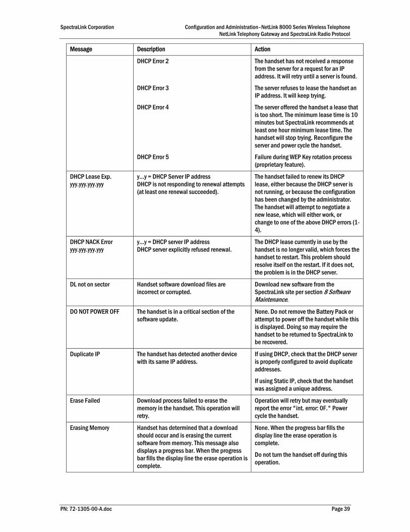
Message Description Action
DHCP Error 2 The handset has not received a response from the server for a request for an IP address. It will retry until a server is found.
DHCP Error 3 The server refuses to lease the handset an IP address. It will keep trying.
DHCP Error 4 The server offered the handset a lease that is too short. The minimum lease time is 10 minutes but SpectraLink recommends at least one hour minimum lease time. The handset will stop trying. Reconfigure the server and power cycle the handset.
DHCP Error 5 Failure during WEP Key rotation process (proprietary feature).
DHCP Lease Exp. yyy.yyy.yyy.yyy
y…y = DHCP Server IP address DHCP is not responding to renewal attempts (at least one renewal succeeded).
The handset failed to renew its DHCP lease, either because the DHCP server is not running, or because the configuration has been changed by the administrator. The handset will attempt to negotiate a new lease, which will either work, or change to one of the above DHCP errors (1-4).
DHCP NACK Error yyy.yyy.yyy.yyy
y…y = DHCP server IP address DHCP server explicitly refused renewal.
The DHCP lease currently in use by the handset is no longer valid, which forces the handset to restart. This problem should resolve itself on the restart. If it does not, the problem is in the DHCP server.
DL not on sector Handset software download files are incorrect or corrupted.
Download new software from the SpectraLink site per section 8 Software Maintenance.
DO NOT POWER OFF The handset is in a critical section of the software update.
None. Do not remove the Battery Pack or attempt to power off the handset while this is displayed. Doing so may require the handset to be returned to SpectraLink to be recovered.
Duplicate IP The handset has detected another device with its same IP address.
If using DHCP, check that the DHCP server is properly configured to avoid duplicate addresses.
If using Static IP, check that the handset was assigned a unique address.
Erase Failed Download process failed to erase the memory in the handset. This operation will retry.
Operation will retry but may eventually report the error "int. error: 0F." Power cycle the handset.
Erasing Memory Handset has determined that a download should occur and is erasing the current software from memory. This message also displays a progress bar. When the progress bar fills the display line the erase operation is complete.
None. When the progress bar fills the display line the erase operation is complete.
Do not turn the handset off during this operation.
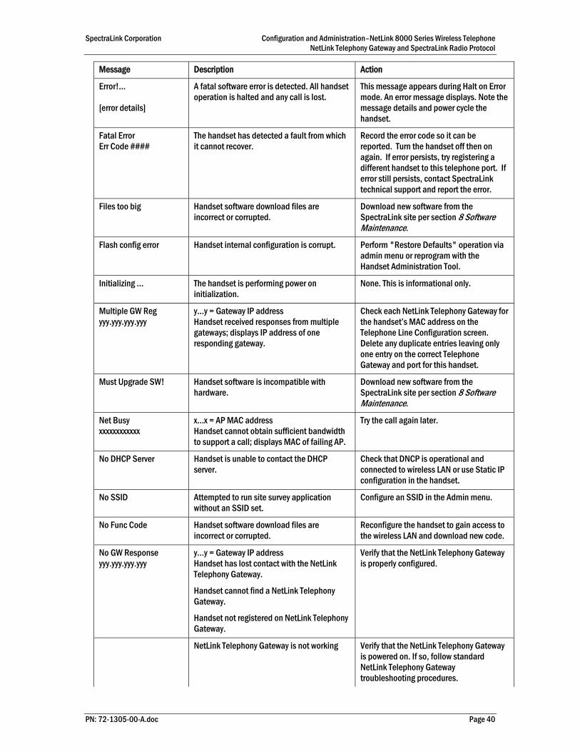
SpectraLink Corporation Configuration and Administration–NetLink 8000 Series Wireless Telephone NetLink Telephony Gateway and SpectraLink Radio Protocol
PN: 72-1305-00-A.doc Page 40
Message Description Action
Error!... [error details]
A fatal software error is detected. All handset operation is halted and any call is lost.
This message appears during Halt on Error mode. An error message displays. Note the message details and power cycle the handset.
Fatal Error Err Code ####
The handset has detected a fault from which it cannot recover.
Record the error code so it can be reported. Turn the handset off then on again. If error persists, try registering a different handset to this telephone port. If error still persists, contact SpectraLink technical support and report the error.
Files too big Handset software download files are incorrect or corrupted.
Download new software from the SpectraLink site per section 8 Software Maintenance.
Flash config error Handset internal configuration is corrupt. Perform "Restore Defaults" operation via admin menu or reprogram with the Handset Administration Tool.
Initializing … The handset is performing power on initialization.
None. This is informational only.
Multiple GW Reg yyy.yyy.yyy.yyy
y…y = Gateway IP address Handset received responses from multiple gateways; displays IP address of one responding gateway.
Check each NetLink Telephony Gateway for the handset’s MAC address on the Telephone Line Configuration screen. Delete any duplicate entries leaving only one entry on the correct Telephone Gateway and port for this handset.
Must Upgrade SW! Handset software is incompatible with hardware.
Download new software from the SpectraLink site per section 8 Software Maintenance.
Net Busy xxxxxxxxxxxx
x…x = AP MAC address Handset cannot obtain sufficient bandwidth to support a call; displays MAC of failing AP.
Try the call again later.
No DHCP Server Handset is unable to contact the DHCP server.
Check that DNCP is operational and connected to wireless LAN or use Static IP configuration in the handset.
No SSID Attempted to run site survey application without an SSID set.
Configure an SSID in the Admin menu.
No Func Code Handset software download files are incorrect or corrupted.
Reconfigure the handset to gain access to the wireless LAN and download new code.
No GW Response yyy.yyy.yyy.yyy
y…y = Gateway IP address Handset has lost contact with the NetLink Telephony Gateway.
Handset cannot find a NetLink Telephony Gateway.
Handset not registered on NetLink Telephony Gateway.
Verify that the NetLink Telephony Gateway is properly configured.
NetLink Telephony Gateway is not working Verify that the NetLink Telephony Gateway is powered on. If so, follow standard NetLink Telephony Gateway troubleshooting procedures.
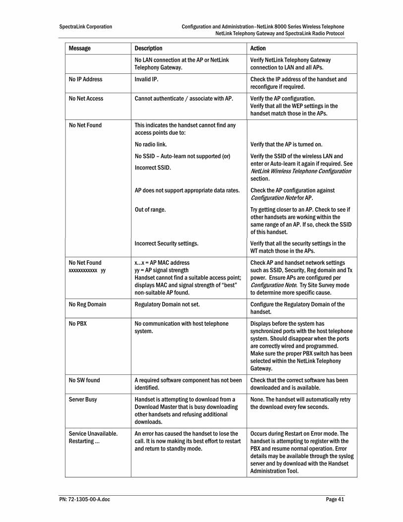
SpectraLink Corporation Configuration and Administration–NetLink 8000 Series Wireless Telephone NetLink Telephony Gateway and SpectraLink Radio Protocol
PN: 72-1305-00-A.doc Page 41
Message Description Action
No LAN connection at the AP or NetLink Telephony Gateway.
Verify NetLink Telephony Gateway connection to LAN and all APs.
No IP Address Invalid IP. Check the IP address of the handset and reconfigure if required.
No Net Access Cannot authenticate / associate with AP. Verify the AP configuration. Verify that all the WEP settings in the handset match those in the APs.
This indicates the handset cannot find any access points due to:
No radio link. Verify that the AP is turned on.
No SSID – Auto-learn not supported (or)
Incorrect SSID.
Verify the SSID of the wireless LAN and enter or Auto-learn it again if required. See NetLink Wireless Telephone Configuration section.
AP does not support appropriate data rates. Check the AP configuration against Configuration Note for AP.
No Net Found
Out of range. Try getting closer to an AP. Check to see if other handsets are working within the same range of an AP. If so, check the SSID of this handset.
Incorrect Security settings. Verify that all the security settings in the WT match those in the APs.
No Net Found xxxxxxxxxxxx yy
x…x = AP MAC address yy = AP signal strength Handset cannot find a suitable access point; displays MAC and signal strength of “best” non-suitable AP found.
Check AP and handset network settings such as SSID, Security, Reg domain and Tx power. Ensure APs are configured per Configuration Note. Try Site Survey mode to determine more specific cause.
No Reg Domain Regulatory Domain not set. Configure the Regulatory Domain of the handset.
No PBX No communication with host telephone system.
Displays before the system has synchronized ports with the host telephone system. Should disappear when the ports are correctly wired and programmed. Make sure the proper PBX switch has been selected within the NetLink Telephony Gateway.
No SW found A required software component has not been identified.
Check that the correct software has been downloaded and is available.
Server Busy Handset is attempting to download from a Download Master that is busy downloading other handsets and refusing additional downloads.
None. The handset will automatically retry the download every few seconds.
Service Unavailable. Restarting …
An error has caused the handset to lose the call. It is now making its best effort to restart and return to standby mode.
Occurs during Restart on Error mode. The handset is attempting to register with the PBX and resume normal operation. Error details may be available through the syslog server and by download with the Handset Administration Tool.

SpectraLink Corporation Configuration and Administration–NetLink 8000 Series Wireless Telephone NetLink Telephony Gateway and SpectraLink Radio Protocol
PN: 72-1305-00-A.doc Page 42
Message Description Action
Storing Config Handset is storing changes to handset configuration.
None. Informational only. The handset may display this briefly following a configuration change or software download.
System Busy yyy.yyy.yyy.yyy
y…y = SVP Server/Telephony Gateway IP Address Gateway or SVP server has reached call capacity; displays IP address of Gateway/SVP Server.
All call paths are in use. Try the call again in a few minutes.
System Locked (with Busy Tone)
Gateway is locked. Try the call again, the system has been locked for maintenance.
TFTP ERROR(x):yy A failure has occurred during a TFTP software download. (x) = The file number which was being downloaded; yy is an error code describing the particular failure. Possible error codes are:
01 = TFTP server did not find the requested file.
02 = Access violation (reported from TFTP server).
07 = TFTP server reported "No such user" error.
81 = File put into memory did not CRC.
FF = Timeout error. TFTP server did not respond within a specified period of time.
Error code 01, 02 or 07 - check the TFTP server configuration.
Error code 81, the handset will attempt to download the file again.
For other messages, power off the handset, then turn it on again to retry the download. If the error repeats, note it and contact SpectraLink technical support.
Too many errors The handset continues to reset and cannot be recovered.
Fatal error. Return handset to SpectraLink.
Unknown xx:yy:zz
A phrase is missing from the phintl file. Download new software from the SpectraLink site per section 8 Software Maintenance.
Updating … The handset is internally updating its software images
None. The handset may do this briefly after a download. This is informational only.
Updating Code Handset is downloading new software into memory. The number icons at the bottom of the display indicate which file number is currently being downloaded. This message also displays a progress bar. When the progress bar fills the display line the update operation is complete on that file.
None. When the progress bar fills the display line the update operation is complete on that file.
Do not turn the handset off during this operation.
Wrong Code Type The software loaded into the handset is the wrong type for this model handset.
Verify the license type is set correctly.
If the license type is correct, replace the software image on the TFTP server with the software that is correct for the handset model.
Waiting Handset has attempted some operation several times and failed and is now waiting for a period of time before attempting that operation again.
None. The handset is waiting for a specified period of time before attempting that operation again.

SpectraLink Corporation Configuration and Administration–NetLink 8000 Series Wireless Telephone NetLink Telephony Gateway and SpectraLink Radio Protocol
Index
Access point Coverage, 28 Coverage test, 33
Audio problems, 37
Capacity, 36
Checking code, 34
Customer Support Hotline, 5
Dial tone, 37
Download messages Failure or Recovery, 34 Normal, 34
Erasing memory, 34
Hotline, 5
Modes, Wireless Telephone, 11
No dialtone, 37
Obstructions, 36
Out of range, 36
Regulatory Domain, 19
Restore Defaults, 20
SpectraLink Voice Priority (SVP) Description, 6
Status messages, 38
Transmission obstructions, 36
Updating code, 34
User Preferences, 12
Wireless Telephone Audio problems, 37 Configuration problems, 36 Configure Preferences, 12 Dial tone problems, 37 Infrastructure problems, 37 Problems with, 36 Status messages, 38
PN: 72-1305-00-A.doc Page 43