netgear model fs526t smart fast ethernet switch
TRANSCRIPT
Page 1 of 58 Page 1 of 58

© 2003 by NETGEAR, Inc. All rights reserved.
Trademarks @2003 NETGEAR, Inc. NETGEAR, the Netgear logo, The Gear Guy and Everybody’s connecting are trademarks of Netgear, Inc. in the United States and/or other countries. Other brand and product names are trademarks of their respective holders. Information is subject to change without notice. All rights reserved.
Statement of Conditions In the interest of improving internal design, operational function, and/or reliability, NETGEAR reserves the right to make changes to the products described in this document without notice. NETGEAR does not assume any liability that may occur due to the use or application of the product(s) or circuit layout(s) described herein.
Certificate of the Manufacturer/Importer It is hereby certified that the NETGEAR Model FS526T 26-Port 10/100 Mbps Smart Fast Ethernet Switch with Gigabit Ports has been suppressed in accordance with the conditions set out in the BMPT-AmtsblVfg 243/1991 and Vfg 46/1992.The operation of some equipment (for example, test transmitters) in accordance with the regulations may, however, be subject to certain restrictions. Please refer to the notes in the operating instructions.
Federal Office for Telecommunications Approvals has been notified of the placing of this equipment on the market and has been granted the right to test the series for compliance with the regulations.
Voluntary Control Council for Interference (VCCI) Statement This equipment is in the first category (information equipment to be used in commercial and/or industrial areas) and conforms to the standards set by the Voluntary Control Council for Interference by Data Processing Equipment and Electronic Office Machines that are aimed at preventing radio interference in commercial and/or industrial areas.
Consequently, when this equipment is used in a residential area or in an adjacent area thereto, radio interference may be caused to equipment such as radios and TV receivers.
Federal Communications Commission (FCC) Compliance Notice: Radio Frequency Notice
This device complies with part 15 of the FCC Rules. Operation is subject to the following two conditions: This device may not cause harmful interference.
This device must accept any interference received, including interference that may cause undesired operation. Note: This equipment has been tested and found to comply with the limits for a Class A digital device, pursuant to part 15 of the FCC Rules. These limits are designed to provide reasonable protection against harmful interference in a residential installation. This equipment generates, uses, and can radiate radio frequency energy and, if not installed and used in accordance with the instructions, may cause harmful interference to radio communications. However, there is no guarantee that interference will not occur in a particular installation. If this equipment does cause harmful interference to radio or television reception, which can be determined by turning the equipment off and on, the user is encouraged to try to correct the interference by one or more of the following measures:
Reorient or relocate the receiving antenna.
Increase the separation between the equipment and receiver.
Connect the equipment into an outlet on a circuit different from that which the receiver is connected.
Consult the dealer or an experienced radio/TV technician for help.
EN 55 022 Declaration of Conformance This is to certify that the NETGEAR Model FS526T 26-Port 10/100 Mbps Smart Fast Ethernet Switch with Gigabit Ports is shielded against the generation of radio interference in accordance with the application of Council Directive 89/336/EEC, Article 4a. Conformity is declared by the application of EN 55024 Class A (CISPR 22).
EN 55 022 and EN 55 024 Statements
This is to certify that the NETGEAR Model FS526T 26-Port 10/100 Mbps Smart Fast Ethernet Switch with Gigabit Ports is shielded against the generation of radio interference in accordance with the application of Council Directive 89/336/EEC, Article 4a. Conformity is declared by the application of EN 55 022 Class A (CISPR 22) and EN 55 024.
Page 2 of 58

Warning: This is a Class A product. In a domestic environment, this product may cause radio interference, in which case the user may be required to take appropriate measures.
Canadian Department of Communications Radio Interference Regulations This digital apparatus (NETGEAR Model FS526T 26-Port 10/100 Mbps Smart Fast Ethernet Switch with Gigabit Ports) do not exceed the Class A limits for radio-noise emissions from digital apparatus as set out in the Radio Interference Regulations of the Canadian Department of Communications.
Règlement sur le brouillage radioélectrique du ministère des Communications Cet appareil numérique (NETGEAR Model FS526T 26-Port 10/100 Mbps Smart Fast Ethernet Switch with Gigabit Ports) respecte les limites de bruits radioélectriques visant les appareils numériques de classe A prescrites dans le Règlement sur le brouillage radioélectrique du ministère des Communications du Canada.
Customer Support For assistance with installing and configuring your NETGEAR system or with questions or problems following installation:
• Check the NETGEAR Web page at http://www.NETGEAR.com.
• Call Technical Support in North America at 1-888-NETGEAR. If you are outside North America, please refer to the phone numbers listed on the Support Information Card that shipped with your switch.
• Email Technical Support at [email protected].
Defective or damaged merchandise can be returned to your point-of-purchase representative.
Internet/World Wide Web NETGEAR maintains a World Wide Web home page that you can access at the uniform resource locator (URL) http://www.NETGEAR.com. A direct connection to the Internet and a Web browser such as Internet Explorer or Netscape are required.
Page 3 of 58
CONTENTS
CHAPTER 1: SWITCH MANAGEMENT OVERVIEW ...................................................................................................................................................................7 Management Access Overview ..........................................................................................................................................................................................7
CHAPTER 2: GETTING STARTED ............................................................................................................................................................................................8 NETWORK WITH DHCP SERVER: ................................................................................................................................................................................8
GearDiscovery > Discover .................................................................................................................................................................................................8 GearDiscovery > Web Access ............................................................................................................................................................................................9 Web Management...........................................................................................................................................................................................................10
NETWORK WITHOUT DHCP SERVER..........................................................................................................................................................................11 GearDiscovery > Configuration Setting > Default ................................................................................................................................................................11 GearDiscovery > Configuration Setting > Assign Static IP....................................................................................................................................................12 NIC setting on the PC that accesses FS526T.....................................................................................................................................................................13 Web Management...........................................................................................................................................................................................................14
CHAPTER 3: SOFTWARE UPGRADE PROCEDURE................................................................................................................................................................15 CHAPTER 4: GEARDISCOVERY UTILITY PROGRAM .............................................................................................................................................................17
Main Screen ...................................................................................................................................................................................................................17 Main Screen> Device List> Discover .................................................................................................................................................................................18 Main Screen> Switch Setting> Configuration Setting...........................................................................................................................................................19 Main Screen> Switch Setting> Password Change ..............................................................................................................................................................19 Main Screen> Switch Setting> Web Access .......................................................................................................................................................................20 Main Screen> Switch Setting> Firmware Upgrade ..............................................................................................................................................................21 Main Screen> Switch Setting> Exit ...................................................................................................................................................................................21
CHAPTER 5: WEB MANAGEMENT ACCESS ..........................................................................................................................................................................22 System ..........................................................................................................................................................................................................................23 System> Switch Status ....................................................................................................................................................................................................23 System> IP Access List ...................................................................................................................................................................................................28 System> Set-up ..............................................................................................................................................................................................................30 System> Password .........................................................................................................................................................................................................31 Switch ...........................................................................................................................................................................................................................32 Switch> Port Configuration...............................................................................................................................................................................................32 Switch> Statistics............................................................................................................................................................................................................36 Switch> VLAN ................................................................................................................................................................................................................37 Switch> VLAN> Port-based VLAN ....................................................................................................................................................................................37 Switch> VLAN> IEEE802.1Q Tag VLAN............................................................................................................................................................................40 Switch> Trunking ............................................................................................................................................................................................................45 Firmware........................................................................................................................................................................................................................47 Firmware> Configuration Backup ......................................................................................................................................................................................47 Firmware> Factory Reset.................................................................................................................................................................................................49 Logout ...........................................................................................................................................................................................................................50
APPENDIX A: DEFAULT SETTINGS .......................................................................................................................................................................................51 APPENDIX B: VIRTUAL LOCAL AREA NETWORK (VLAN) IEEE 802.1Q ..................................................................................................................................52 APPENDIX C: VIRTUAL LOCAL AREA NETWORK (VLAN): PORT-BASED VLAN ..........................................................................................57
Page 4 of 58

Figures FIGURE 2-1. GEARDISCOVERY UTILITY MAIN SCREEN..........................................................................................................................................................8 FIGURE 2-2. WEB ACCESS ....................................................................................................................................................................................................................9 FIGURE 2-3. WEB MANAGEMENT FRONT PAGE AFTER CLICK “WEB ACCESS” ON GEARDISCOVERY UTILITY......................................10 FIGURE 2-4. CONFIGURATION SETTING ......................................................................................................................................................................................11 FIGURE 2-5. MANUALLY SETTING IP ADDRESS........................................................................................................................................................................12 FIGURE 2-6. SETTING IP ADDRESS AND SUBNET MASK .....................................................................................................................................................13 FIGURE 2-7. WEB MANAGEMENT FRONT PAGE AFTER CLICK “WEB ACCESS” ON GEARDISCOVERY UTILITY......................................14 FIGURE 3-1. SELECT THE SWITCH YOU WANT TO UPGRADE AND CLICK FIRMWARE UPGRADE.................................................................15 FIGURE 3-2. LOCATE NEW FIRMWARE. ........................................................................................................................................................................................16 FIGURE 3-3. ENTER PASSWORD AND CLICK START. ............................................................................................................................................................16 FIGURE 4-1. GEARDISCOVERY UTILITY MAIN SCREEN........................................................................................................................................................17 FIGURE 4-2. MAIN SCREEN: DEVICE LIST> DISCOVER.........................................................................................................................................................18 FIGURE 4-3. MAIN SCREEN: SWITCH SETTING> CONFIGURATION SETTING............................................................................................................19 FIGURE 4-4. MAIN SCREEN: SWITCH SETTING> PASSWORD CHANGE .......................................................................................................................19 FIGURE 4-5. WEB MANAGEMENT LOGIN PAGE ........................................................................................................................................................................20 FIGURE 4-6. MAIN SCREEN: SWITCH SETTING> FIRMWARE UPGRADE ......................................................................................................................21 FIGURE 5-1. WEB MANAGEMENT LOGIN PAGE ........................................................................................................................................................................22 FIGURE 5-2. SYSTEM> SWITCH STATUS: SWITCH STATUS ...............................................................................................................................................23 FIGURE 5-3. SYSTEM> SWITCH STATUS: PORT STATUS ....................................................................................................................................................24 FIGURE 5-4. SYSTEM> SWITCH STATUS: PORT-BASED VLAN & TRUNK .....................................................................................................................25 FIGURE 5-5. SYSTEM> SWITCH STATUS: TAG VLAN PVID TABLE...................................................................................................................................26 FIGURE 5-6. SYSTEM> SWITCH STATUS: TAG VLAN SETTINGS ......................................................................................................................................27 FIGURE 5-7. SYSTEM> IP ACCESS LIST........................................................................................................................................................................................28 FIGURE 5-8. SYSTEM> IP ACCESS LIST> ADD NEW IP..........................................................................................................................................................29 FIGURE 5-9. SYSTEM> SET-UP> SYSTEM SETTING ...............................................................................................................................................................30 FIGURE 5-10. SYSTEM> PASSWORD> PASSWORD SETTING............................................................................................................................................31 FIGURE 5-11. SWITCH> PORT CONFIGURATION> PORT SETTING MENU...................................................................................................................32 FIGURE 5-12. SWITCH> PORT CONFIGURATION> PORT SETTINGS: SPEED.............................................................................................................33 FIGURE 5-13. SWITCH> PORT CONFIGURATION> PORT SETTINGS: FLOW CONTROL ........................................................................................34 FIGURE 5-14. SWITCH> PORT CONFIGURATION> PORT SETTINGS: QOS..................................................................................................................35 FIGURE 5-15. SWITCH> STATISTICS...............................................................................................................................................................................................36 FIGURE 5-16. SWITCH> VLAN.............................................................................................................................................................................................................37 FIGURE 5-17. SWITCH> VLAN SETTING> PORT-BASED VLAN: ADD GROUP..............................................................................................................38 FIGURE 5-18. SWITCH> VLAN SETTING> PORT-BASED VLAN: DELETE GROUP......................................................................................................39 FIGURE 5-19. SWITCH> VLAN SETTING> TAG VLAN...............................................................................................................................................................40 FIGURE 5-20. SWITCH> VLAN SETTING> TAG VLAN: DEFAULT ........................................................................................................................................40 FIGURE 5-21. SWITCH> VLAN SETTING> TAG VLAN MENU ................................................................................................................................................41 FIGURE 5-22. SWITCH> VLAN SETTING> TAG VLAN: ADD NEW VLAN ..........................................................................................................................42 FIGURE 5-23. SWITCH> VLAN SETTING> TAG VLAN: DELETE A VLAN ..........................................................................................................................43 FIGURE 5-24. SWITCH> VLAN SETTING> TAG VLAN: PVID SETTING .............................................................................................................................44 FIGURE 5-25. SWITCH> TRUNK SETTING.....................................................................................................................................................................................45 FIGURE 5-26. SWITCH> TRUNK SETTING: TRUNK GROUP 01 ...........................................................................................................................................46 FIGURE 5-30. FIRMWARE> CONFIGURATION BACKUP> BACKUP SETTING: BACKUP ..........................................................................................47 FIGURE 5-31. FIRMWARE> CONFIGURATION BACKUP> BACKUP SETTING: RESTORE.......................................................................................48 FIGURE 5-32. FIRMWARE> CONFIGURATION BACKUP> BACKUP SETTING: REBOOT .........................................................................................48 FIGURE 5-33. FIRMWARE> FACTORY RESET ............................................................................................................................................................................49 FIGURE 5-34. FIRMWARE> FACTORY RESET: REBOOT .......................................................................................................................................................50
Page 5 of 58

Tables TABLE 1-1. COMPARING SWITCH MANAGEMENT METHODS ......................................................................................................................................................7 TABLE A-1. DEFAULT SETTINGS...........................................................................................................................................................................................................51
Page 6 of 58

CHAPTER 1: SWITCH MANAGEMENT OVERVIEW This chapter gives an overview of switch management, including the methods you can use to manage your NETGEAR Model FS526T 26-Port 10/100 Mbps Smart Fast Ethernet Switch with Gigabit Ports. Topics include:
Management Access Overview
Management Access Overview Your NETGEAR Model FS526T 26-Port 10/100 Mbps Smart Fast Ethernet Switch with Gigabit Ports contains software for viewing, changing, and monitoring the way it works. This management software is not required for the switch to work. You can use the 10/100 Mbps ports and the built-in Gigabit ports without using the management software. However, the management software allows you configure ports, VLAN and Trunking features and also improve the efficiency of the switch and, as a result, improve the overall performance of your network. The Switch gives you the flexibility to access and manage the switch using any of the following methods:
GearDiscovery Utility program
Web browser interface
After you power-up the switch for the first time, you can configure it using a utility program called GearDiscovery or a Web browser. Please refer to the screenshots in following pages for GearDiscovery Utility and Web Management GUI. Each of these management methods has advantages. Table 1-1 compares the three management methods.
Table 1-1. Comparing Switch Management Methods
Management Method Advantages
GearDiscovery Utility program
No IP address or subnet needed Show all switches on the network User-friendly interface Firmware upgradeable
Web browser
Can be accessed from any location via the switch’s IP address Password protected Ideal for configuring the switch remotely Compatible with Internet Explorer and Netscape Navigator Web browsers Intuitive browser interface More visually appealing Extensive switch configuration allowed Configuration backup for duplicating settings to other switches
For a more detailed discussion of the GearDiscovery Utility Program, see chapter 4. For a more detailed discussion of the Web Browser Interface, see chapter 5.
Page 7 of 58

CHAPTER 2: Getting Started This chapter will walk you through the steps to start managing your FS526T switch. This chapter will cover how to get started in a network with a DHCP server (most common) as well as if you do not have a DHCP server. Network with DHCP server: 1. Connect FS526T to a DHCP network. 2. Power on FS526T by plugging in power cord. 3. Install GearDiscovery Utility program on your computer 4. Start GearDiscovery utility. (Chapter 4 has detailed instructions on the GearDiscovery utility) 5. Click Discover for the GearDiscovery to find your FS526T switch. You should see a something similar to Figure 2-1. GearDiscovery > Discover
Figure 2-1. GearDiscovery Utility Main Screen
Page 8 of 58
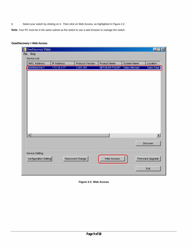
6. Select your switch by clicking on it. Then click on Web Access, as highlighted in Figure 2-2. Note: Your PC must be in the same subnet as the switch to use a web browser to manage the switch. GearDiscovery > Web Access
Figure 2-2. Web Access
Page 9 of 58

7. Start managing your switch via your web browser. The default password is ‘password’. For a detailed description on web management, please refer to Chapter 5. Web Management
Figure 2-3. Web Management Front page after click “web access” on GearDiscovery utility
Page 10 of 58

Network without DHCP server 1. Connect FS526T to your existing network. 2. Power on FS526T by plugging in power cord. 3. Install GearDiscovery Utility program on your computer. 4. Start GearDiscovery Utility. (Default IP is 192.168.0.239. Chapter 4 has detailed instructions on the GearDiscovery Utility) 5. Click Discover for the GearDiscovery program to find your FS526T switch. You should see a something similar to Figure 2-1. 6. Click on Configuration Setting (See figure 2-4). Note: You can always assign a Static IP address to your FS526T whether or not your network has a DHCP server. GearDiscovery > Configuration Setting > Default
Figure 2-4. Configuration Setting
Page 11 of 58

7. Choose Disable on DHCP. See Figure 2-5. 8. Enter your IP address, Gateway and Subnet, and then type your password and click “Set”. Please make sure your PC and FS526T
are in the same subnet. (See Figure 2-6.) GearDiscovery > Configuration Setting > Assign Static IP
Figure 2-5. Manually setting IP address
Page 12 of 58

NIC setting on the PC that accesses FS526T
Figure 2-6. Setting IP address and Subnet Mask
Page 13 of 58

9. Select your switch by clicking on it. Then click on Web Access, as highlighted in Figure 2-2. 10. Start managing your switch via your web browser. The default password is ‘password’. For a detailed description on web
management access, please refer to Chapter 5. Web Management
Figure 2-7. Web Management Front page after click “web access” on GearDiscovery utility
Page 14 of 58

CHAPTER 3: Software Upgrade Procedure The application software for the FS526T is upgradeable, enabling your switch to take advantage of improvements and additional features as they become available. The upgrade procedure and the required equipment are described in the following section. The upgrade procedure is as follow: 1. Save the new firmware to your computer. 2. Start the GearDiscovery utility program. 3. Select your switch by clicking on it. Then click on Firmware Upgrade, as highlighted in Figure 3-1.
Figure 3-1. Select the switch you want to upgrade and click Firmware Upgrade.
Page 15 of 58
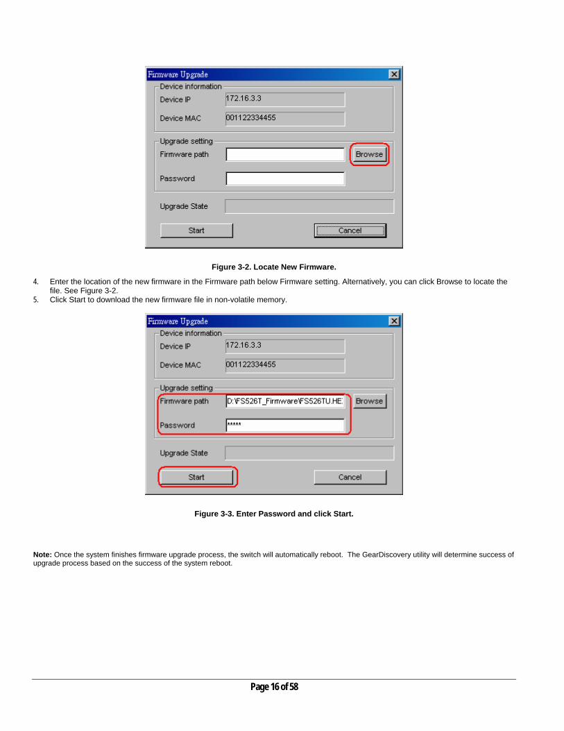
Figure 3-2. Locate New Firmware.
4. Enter the location of the new firmware in the Firmware path below Firmware setting. Alternatively, you can click Browse to locate the file. See Figure 3-2.
5. Click Start to download the new firmware file in non-volatile memory.
Figure 3-3. Enter Password and click Start.
Note: Once the system finishes firmware upgrade process, the switch will automatically reboot. The GearDiscovery utility will determine success of upgrade process based on the success of the system reboot.
Page 16 of 58
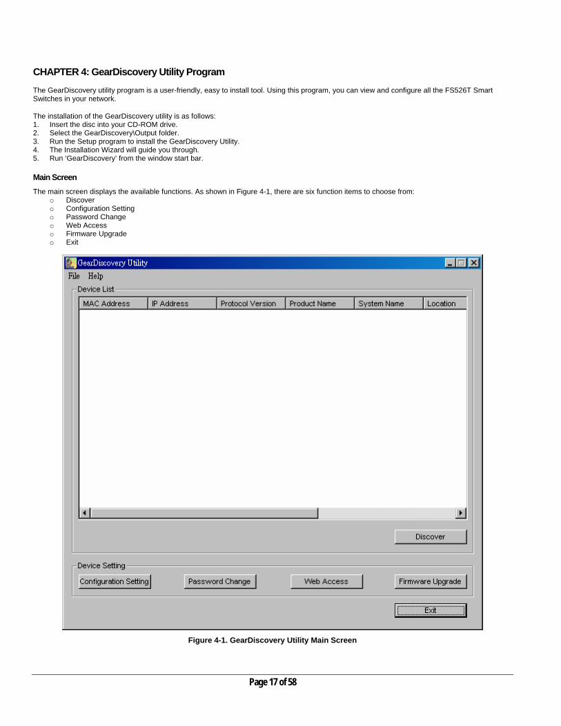
CHAPTER 4: GearDiscovery Utility Program The GearDiscovery utility program is a user-friendly, easy to install tool. Using this program, you can view and configure all the FS526T Smart Switches in your network. The installation of the GearDiscovery utility is as follows: 1. Insert the disc into your CD-ROM drive. 2. Select the GearDiscovery\Output folder. 3. Run the Setup program to install the GearDiscovery Utility. 4. The Installation Wizard will guide you through. 5. Run ‘GearDiscovery’ from the window start bar. Main Screen The main screen displays the available functions. As shown in Figure 4-1, there are six function items to choose from:
o Discover o Configuration Setting o Password Change o Web Access o Firmware Upgrade o Exit
Figure 4-1. GearDiscovery Utility Main Screen
Page 17 of 58

Main Screen> Device List> Discover The GearDiscovery can discover all switches currently connected on the network. Click ‘Discover’ to view the following switch information of any listed switch:
MAC Address
IP Address
Protocol Version
Product Name
System Name
Location
DHCP
Subnet Mask
Gateway
.
Figure 4-2. Main Screen: Device List> Discover
By double-clicking a listed switch, you can open the Web management for that switch. Alternatively, you can select a switch by clicking on it once, and then clicking Web Access. For more information on Web management, see Chapter 5.
Page 18 of 58

Main Screen> Switch Setting> Configuration Setting Select a switch by clicking on it. Then click Configuration Setting. The following screen pops up, enabling you modify:
o System Name This field is to help you keep track of your switches. It can be any combination of letters and/or numbers. o Location This field is to help you keep track of where this switch is. It can be any combination of letters and/or numbers. o Password The default password is ‘password’. You must enter your password for and modifications to take affect. o DHCP DHCP automatically obtains the IP information for the switch.
Figure 4-3. Main Screen: Switch Setting> Configuration Setting
o System Name Any desired description for System Name. o Location Any desired description for Location. o Password The default password is ‘password’. o DHCP This function is enabled by default. Click ‘Disable’ to abort the function.
Main Screen> Device Setting> Configuration Setting> Set
Click ‘Set’ to enable new settings. You must enter your password for these settings to be accepted.
Main Screen> Device Setting> Configuration Setting> Cancel
Click ‘Cancel’ to abort the above settings. Main Screen> Switch Setting> Password Change Click ‘Password Change’ from the Switch Setting section. The following screen pops up as shown in Figure 4-4.
Figure 4-4. Main Screen: Switch Setting> Password Change
o New Password Type any desired password. Passwords are case-sensitive and can have a maximum of 20 characters. o Confirm Password Re-type the new password to confirm it. o Old Password The default password is ‘password’.
Click ‘Set’ to enable new password.
Page 19 of 58

Main Screen> Switch Setting> Web Access Select a listed switch from the Device List section. Then click Web Access from the Switch Setting (see Figure 4-5). Enter the default password ‘password’, and click Login. For more on Web management, see Chapter 5.
Figure 4-5. Web Management Login Page
Page 20 of 58

Main Screen> Switch Setting> Firmware Upgrade Click Firmware Upgrade from the Switch Setting section. The following screen will pop up.
Figure 4-6. Main Screen: Switch Setting> Firmware Upgrade
o Firmware Path The location of the new firmware. If you don’t know, you can click Browse to locate file. o Password The default password is ‘password’. o Upgrade State Show upgrading in progress.
Click Start to start upgrading. Main Screen> Switch Setting> Exit Click Exit from the Switch Setting section to close the GearDiscovery Utility program.
Page 21 of 58

CHAPTER 5: WEB MANAGEMENT ACCESS Your NETGEAR Model FS526T 26-Port 10/100 Mbps Smart Fast Ethernet Switch with Gigabit Ports provides a built-in browser interface that lets you configure and manage it remotely using a standard Web browser such as Microsoft Internet Explorer or Netscape Navigator. This interface also allows for system monitoring of the Switch. The help page will cover many of the basic functions and features of the switch and its web interface. Web Management requires either Microsoft Internet Explorer 5.0 or later or Netscape Navigator 6.0 or later. Note: Only one user can be logged in at any time.
Figure 5-1. Web Management Login page There are 3 menu options available:
o System o Switch o Firmware
There is a Help Menu in the top of right side of screen. Click the help to read the full Help Menu. On some pages, there is a Help button. If you click that button, you will go to the part of the Help Menu that discusses that page. Within the various browser interface pages, there are several buttons that you can use. Their names and functions are below:
Refresh: Pulls that screen’s data from current values on the system
Apply: Submits change request to system and refreshes screen data
Add: Adds new entries to table information and refreshes screen data
Browse: Locates a certain path for a desired file. Delete: Deletes selected entries from table and refreshes screen data
Page 22 of 58

Factory Reset: Restore the system factory default value.
Help: Goes to relevant section of Help Menu
System There are 4 options available:
o Switch Status o IP Access List o Set-up o Password
System> Switch Status
System> Switch Status
The top part of this page displays switch information, such as: o Product Name: (NETGEAR FS526T) o Firmware Version o Protocol Version o DHCP: (shows if enabled or disabled) o IP Address o Subnet Mask o Default Gateway o MAC Address o System Name o Location Name o Login Timeout: o System Up Time
These parameters are not editable from this screen. Only System Name and Location Name can be modified in the Set-up> System Setting page.
Figure 5-2. System> Switch Status: Switch Status
Page 23 of 58
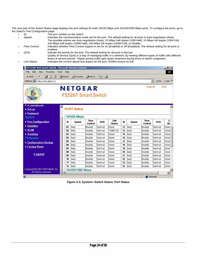
The next part of the Switch Status page displays the port settings for both 10/100 Mbps and 10/100/1000 Mbps ports. To configure the ports, go to the Switch> Port Configuration page.
o ID: The port number on the switch o Speed: Indicates the communication mode set for the port. The default setting for all ports is Auto-negotiation (Auto).
The possible entries are Auto-negotiation (Auto), 10 Mbps half duplex (10M Half), 10 Mbps full duplex (10M Full), 100 Mbps half duplex (100M Half), 100 Mbps full duplex (100M Full), or Disable.
o Flow Control: Indicates whether Flow Control support is set for on (Enabled) or off (Disabled). The default setting for all ports is enabled.
o QOS: Indicate the priority for the port. The default setting for all ports is Normal. Quality of Service (QoS) is a way of managing traffic in a network, by treating different types of traffic with different levels of service priority. Higher priority traffic gets faster treatment during times of switch congestion.
o Link Status: Indicates the current speed and duplex for the port. DOWN means no link.
Figure 5-3. System> Switch Status: Port Status
Page 24 of 58
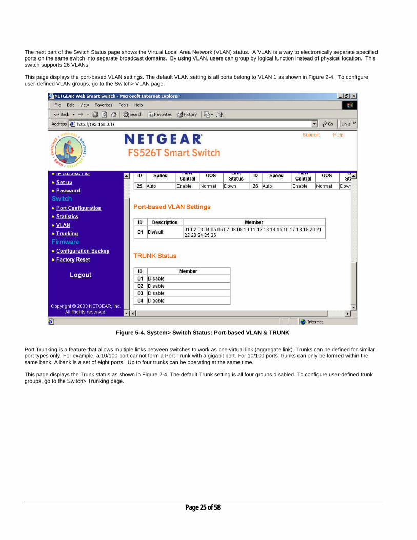
The next part of the Switch Status page shows the Virtual Local Area Network (VLAN) status. A VLAN is a way to electronically separate specified ports on the same switch into separate broadcast domains. By using VLAN, users can group by logical function instead of physical location. This switch supports 26 VLANs. This page displays the port-based VLAN settings. The default VLAN setting is all ports belong to VLAN 1 as shown in Figure 2-4. To configure user-defined VLAN groups, go to the Switch> VLAN page.
Figure 5-4. System> Switch Status: Port-based VLAN & TRUNK Port Trunking is a feature that allows multiple links between switches to work as one virtual link (aggregate link). Trunks can be defined for similar port types only. For example, a 10/100 port cannot form a Port Trunk with a gigabit port. For 10/100 ports, trunks can only be formed within the same bank. A bank is a set of eight ports. Up to four trunks can be operating at the same time. This page displays the Trunk status as shown in Figure 2-4. The default Trunk setting is all four groups disabled. To configure user-defined trunk groups, go to the Switch> Trunking page.
Page 25 of 58
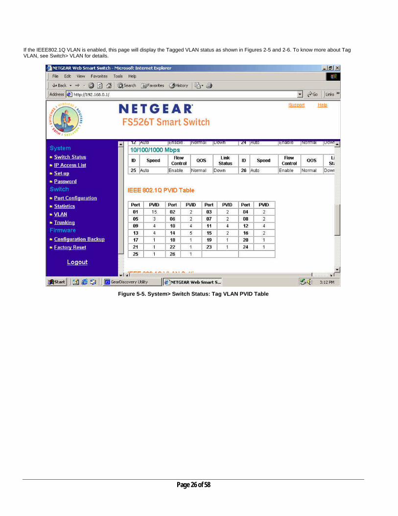
If the IEEE802.1Q VLAN is enabled, this page will display the Tagged VLAN status as shown in Figures 2-5 and 2-6. To know more about Tag VLAN, see Switch> VLAN for details.
Figure 5-5. System> Switch Status: Tag VLAN PVID Table
Page 26 of 58

Figure 5-6. System> Switch Status: Tag VLAN Settings
Page 27 of 58
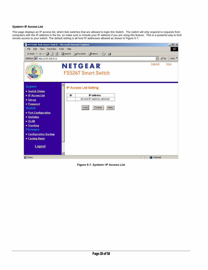
System> IP Access List This page displays an IP access list, which lists switches that are allowed to login this Switch. The switch will only respond to requests from computers with the IP address in the list, so make sure to include your IP address if you are using this feature. This is a powerful way to limit remote access to your switch. The default setting is all host IP addresses allowed as shown in Figure 5-7.
Figure 5-7. System> IP Access List
Page 28 of 58

Add a new entry
o Click Add to bring up the page as shown in Figure 5-8 o Enter site-specific IP address in the appropriate boxes o Click Apply to activate the setting
Note: Once this new IP access is enabled, you can only access the switch via devices with approved IP addresses. Make sure that your current PC has one of the addresses in the list.
Delete an existing entry
o Click Delete to bring up the IP Access List Delete screen o Click to select the entry in the list o Click Apply to delete this IP Access
Figure 5-8. System> IP Access List> Add new IP
Page 29 of 58

System> Set-up This page will allow access to the system information parameters.
o Enter System Name and Location Name o The DHCP function is enabled by default. Click Static IP Address to disable the DHCP function. o Enter site-specific IP address, Subnet mask and Gateway in the appropriate boxes o Click Apply to activate the setting
Figure 5-9. System> Set-up> System Setting
Page 30 of 58

System> Password The password entered is encrypted on the screen and will display as a sequence of asterisks (*). The default password is ‘password’ and can be changed here.
o Type the old password in the Old Password field o Type the new password in the New Password field o Re-type the new password in the Re-type New Password field o Click Apply to activate the new password
Note: The password is case sensitive and with a maximum length of 20.
Figure 5-10. System> Password> Password Setting
Page 31 of 58
Switch There are 4 options available:
o Port Configuration o Statistics o VLAN o Trunking
Switch> Port Configuration
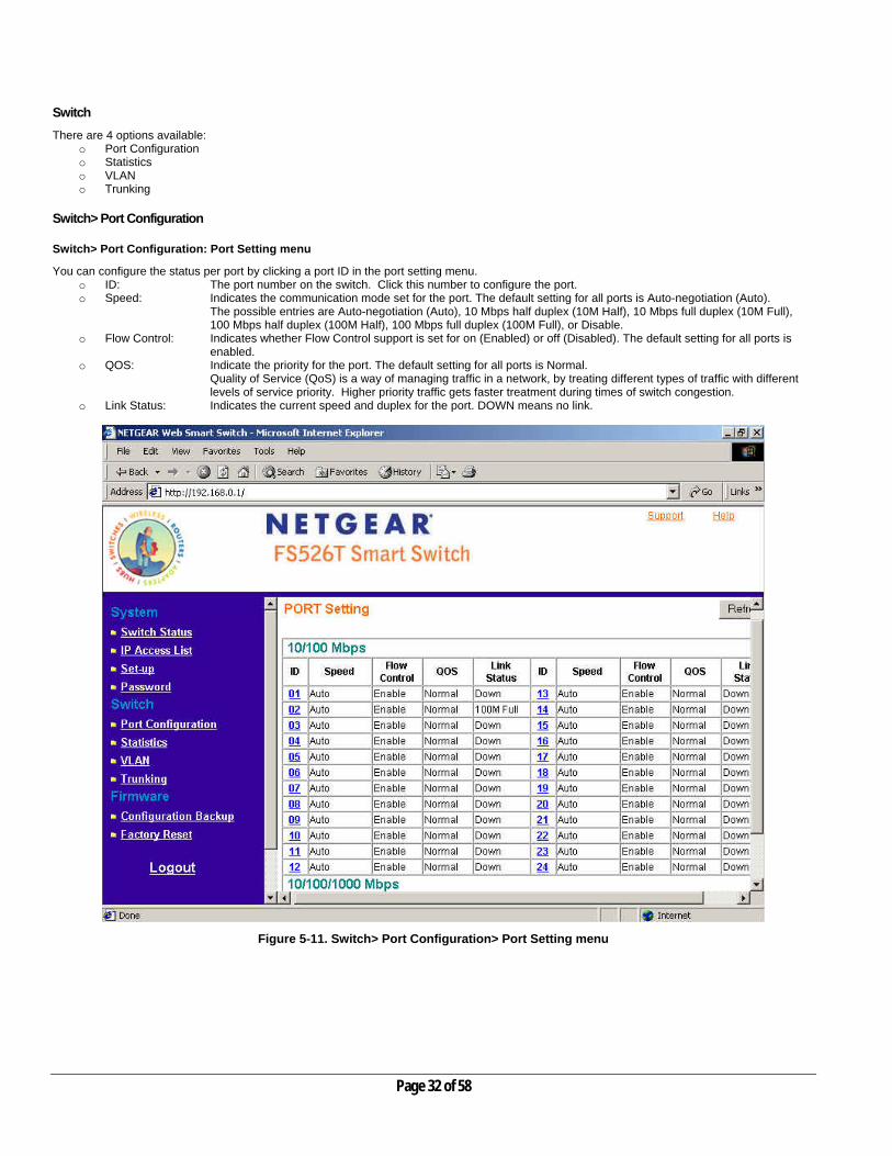
Switch> Port Configuration: Port Setting menu
You can configure the status per port by clicking a port ID in the port setting menu. o ID: The port number on the switch. Click this number to configure the port. o Speed: Indicates the communication mode set for the port. The default setting for all ports is Auto-negotiation (Auto).
The possible entries are Auto-negotiation (Auto), 10 Mbps half duplex (10M Half), 10 Mbps full duplex (10M Full), 100 Mbps half duplex (100M Half), 100 Mbps full duplex (100M Full), or Disable.
o Flow Control: Indicates whether Flow Control support is set for on (Enabled) or off (Disabled). The default setting for all ports is enabled.
o QOS: Indicate the priority for the port. The default setting for all ports is Normal. Quality of Service (QoS) is a way of managing traffic in a network, by treating different types of traffic with different levels of service priority. Higher priority traffic gets faster treatment during times of switch congestion.
o Link Status: Indicates the current speed and duplex for the port. DOWN means no link.
Figure 5-11. Switch> Port Configuration> Port Setting menu
Page 32 of 58

Switch> Port Configuration: Set speed
o Click a port ID as shown in Figure 5-11 o Click to select a speed from the pull-down menu under Speed o Click Apply to activate the new speed
Note: Please be aware that speed must set as same as link partner. Otherwise, packet loss or link error might occur.
Figure 5-12. Switch> Port Configuration> Port Settings: Speed
Page 33 of 58

Switch> Port Configuration: Set flow control
o Click a port ID as shown in Figure 5-11 o Click to select Enable or Disable from the pull-down menu under Flow Control o Click Apply to activate the new setting
Figure 5-13. Switch> Port Configuration> Port Settings: Flow Control
Page 34 of 58

Switch> Port Configuration: Set QOS
o Click a port ID as shown in Figure 5-11 o Click to select Normal or High from the pull-down menu under QOS o Click Apply to activate the new setting
Figure 5-14. Switch> Port Configuration> Port Settings: QOS
Page 35 of 58

Switch> Statistics The Statistics Table shows the statistics types for one port over time.
o ID: The port number on the switch o Tx: Transmitted packet/s. o Rx: Received packet/s. o Tx Error: Transmitted packet/s with an error. o Rx Error: Received packet/s with an error.
Packets are counted as TX Error if they:
• Had a late collision detected during the transmission (512 bit-times into the transmission). • Experienced 16 failed transmission attempts due to collision. • Were dropped due to lack of resources.
Packets are counted as RX Error if they:
• Were less than 64 bytes or greater than 1522 bytes. • Had a bad FCS. • Were dropped due to lack of resources.
Switch> Statistics> Refresh
Click Refresh to obtain current statistics data.
Switch> Statistics> Clear Counter
Click Clear Counter to start new statistics over time.
Figure 5-15. Switch> Statistics
Page 36 of 58

Switch> VLAN A Virtual Local Area Network (VLAN) is a means to electronically separate ports on the same switch from a single broadcast domain into separate broadcast domains. By using VLAN, users can group by logical function instead of physical location. The VLAN Table shows two types of VLAN and other information:
o IEEE 802.1Q VLAN (Tagged VLAN) o Port-based VLAN o ID: The port number on the switch o Description: User-definable o Member: Indicates which port/s belong to a VLAN group
Switch> VLAN> Port-based VLAN There are up to 26 port-based VLAN groups supported on this switch. A port can participate in more than one VLAN group. For port-based VLANs, the default VLAN group is VLAN 01.
Figure 5-16. Switch> VLAN
Page 37 of 58

Change members
o Click a VLAN ID as shown in Figure 5-16 o Click to select port/s for VLAN members o Click Apply to activate the new setting
Add Group
o Click Add Group as shown in Figure 5-16 o Enter a description for this VLAN group o Click to select port/s for VLAN members o Click Set all to select all ports o Click Clear all to unselect all ports o Click Apply to activate the new setting
Figure 5-17. Switch> VLAN Setting> Port-based VLAN: Add Group
Page 38 of 58

Delete Group
o Click Delete Group as shown in Figure 5-16 o Click to select a VLAN ID as shown in Figure 5-18 o Click Apply to confirm delete this VLAN
Figure 5-18. Switch> VLAN Setting> Port-based VLAN: Delete Group
Page 39 of 58
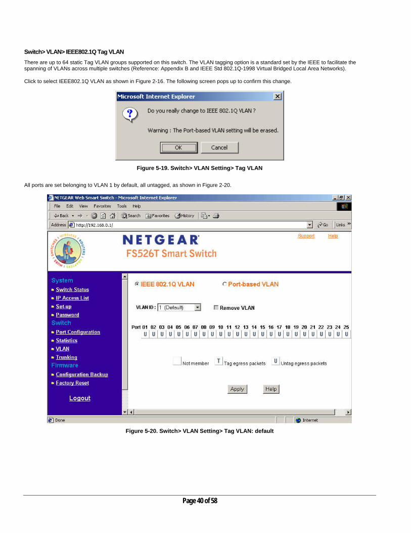
Switch> VLAN> IEEE802.1Q Tag VLAN There are up to 64 static Tag VLAN groups supported on this switch. The VLAN tagging option is a standard set by the IEEE to facilitate the spanning of VLANs across multiple switches (Reference: Appendix B and IEEE Std 802.1Q-1998 Virtual Bridged Local Area Networks). Click to select IEEE802.1Q VLAN as shown in Figure 2-16. The following screen pops up to confirm this change.
Figure 5-19. Switch> VLAN Setting> Tag VLAN
All ports are set belonging to VLAN 1 by default, all untagged, as shown in Figure 2-20.
Figure 5-20. Switch> VLAN Setting> Tag VLAN: default
Page 40 of 58
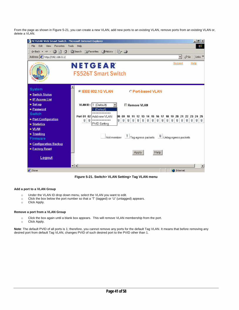
From the page as shown in Figure 5-21, you can create a new VLAN, add new ports to an existing VLAN, remove ports from an existing VLAN or, delete a VLAN.
Figure 5-21. Switch> VLAN Setting> Tag VLAN menu
Add a port to a VLAN Group
o Under the VLAN ID drop down menu, select the VLAN you want to edit. o Click the box below the port number so that a ‘T’ (tagged) or ‘U’ (untagged) appears. o Click Apply.
Remove a port from a VLAN Group
o Click the box again until a blank box appears. This will remove VLAN membership from the port. o Click Apply.
Note: The default PVID of all ports is 1; therefore, you cannot remove any ports for the default Tag VLAN. It means that before removing any desired port from default Tag VLAN, changes PVID of such desired port to the PVID other than 1.
Page 41 of 58

Create a new VLAN Group
o Under the VLAN ID drop down menu, select Add new VLAN. See Figures 2-22 and 2-23 for an example of creating VLAN 2. o Enter the VLAN ID “2” in the provided fields. VLAN ID must be set within 2 ~ 4094. o Add VLAN members if so desired; click the box below the port number so that a ‘T’ (tagged) or ‘U’ (untagged) appears. o Click Apply.
Note: To allow untagged packets to participate in VLAN 2, make sure to change the Port VLAN Ids (PVID) for the relevant ports. Access the PVID Settings by using the VLAN ID drop down menu.
Figure 5-22. Switch> VLAN Setting> Tag VLAN: Add new VLAN
Page 42 of 58

Delete a VLAN Group
o Under the VLAN ID drop down menu, select the VLAN you want to remove. o Click to select Remove VLAN. o Click Apply.
Figure 5-23. Switch> VLAN Setting> Tag VLAN: Delete a VLAN
Page 43 of 58

PVID Setting
All untagged packets entering the switch will by default be tagged with the port’s Primary VLAN Identification (PVID). This screen allows you to specify the PVID for each port. Take VLAN 2 for example: ports 5, 6, 7, and 8 have been checked as tagged ports for this VLAN. You must change the PVID value from “1” to “2” for those ports to avoid losing untagged packets when they are received.
o Under the VLAN ID drop down menu, select PVID Setting. See below for an example of setting PVID for VLAN 2. o Change the PVID value of ports 5, 6, 7, and 8. o Click Apply.
Figure 5-24. Switch> VLAN Setting> Tag VLAN: PVID Setting
Page 44 of 58

Switch> Trunking Port Trunking is a feature that allows multiple links between switches to work as one virtual link (aggregate link). Trunks can be defined for similar port types only. For example, a 10/100 port cannot form a Port Trunk with a gigabit port. For 10/100 ports, trunks can only be formed within the same bank. A bank is a set of eight ports, such as ports 1 to 8, ports 9 to 16, ports 17 to 24, or port 25 and port 26, on the same switch unit. Up to four trunks can be operating at the same time. The Trunk Table shows all four trunking groups are set disabled by default. For each trunk group, trunk members are pre-set for selection.
o Click to select Trunk members from a pull-down menu for a Trunk group o Click Apply to activate the new setting
Note: The selected trunk port setting must set to the same VLAN group.
Figure 5-25. Switch> Trunk Setting
Page 45 of 58

For Trunk Group 01, there are four types of member selection: o Disable: Trunk Group 01 is disabled. o 01, 02: These two ports are trunked as Trunk Group 01. o 01, 02, 03, and 04: These four ports are trunked as Trunk Group 01. o 01 ~ 08: These eight ports are trunked as Trunk Group 01.
The other Trunk Groups behave in a similar manner.
Figure 5-26. Switch> Trunk Setting: Trunk Group 01
Page 46 of 58

Firmware
There are 2 options available: o Configuration Backup o Factory Reset
Firmware> Configuration Backup You can backup the system and switch settings to your workstation. This can help you to reconfigure the switch quickly if you have to re-set to factory defaults. Additionally, if you want to try out different configurations on the switch, this feature will enable you to quickly return to a previous configuration. If you own several switches and you want them to have the same configuration, you can use this feature to duplicate the settings to each switch. Saving your Backup file:
o Click Backup to store the current setting to a file in your PC. o Follow the instructions on the screen to select where you want to store your Backup file.
Restoring your Backup file (or using a duplicate configuration):
o Click Restore to recover the Backup file from your PC to the current switch. If you do not want to type in the path name, click Browse to find the Backup file.
o Click OK in the File Download dialog box as shown in Figure 5-31. o When download process is finished, click OK to confirm disconnection of current browser connection as shown in Figure 5-32.
Note: Please be aware that the switch will reboot after a successful restore. Note: The Backup file does not affect the password or MAC address of the switch
Figure 5-30. Firmware> Configuration Backup> Backup Setting: Backup
Page 47 of 58

Figure 5-31. Firmware> Configuration Backup> Backup Setting: Restore
Figure 5-32. Firmware> Configuration Backup> Backup Setting: Reboot
Page 48 of 58
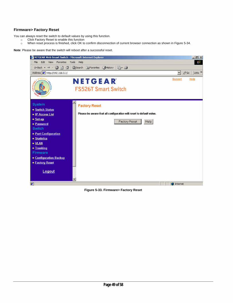
Firmware> Factory Reset You can always reset the switch to default values by using this function.
o Click Factory Reset to enable this function o When reset process is finished, click OK to confirm disconnection of current browser connection as shown in Figure 5-34.
Note: Please be aware that the switch will reboot after a successful reset.
Figure 5-33. Firmware> Factory Reset
Page 49 of 58

Figure 5-34. Firmware> Factory Reset: reboot
Logout When finished with all configuration and settings, click Logout to disconnect the current browser connection. The login page will pop up.
Page 50 of 58

APPENDIX A: DEFAULT SETTINGS This appendix provides default settings for the NETGEAR Model FS526T Smart Fast Ethernet Switch. You can always configure the switch to default settings by using the Factory Reset function from a Web browser.
Table A-1. Default Settings
FEATURE FS526T DEFAULT SETTING
Port Speed Auto-negotiation Port Duplex Auto-negotiation Flow Control (half duplex) Enabled Flow Control (full duplex) Enabled IP Configuration DHCP enabled Default IP address (if no DHCP server) 192.168.0.239 Password password VLAN Port-Based VLAN Link Aggregation (Trunk) Disabled Traffic Prioritization (QoS) All ports set normal priority
Page 51 of 58

APPENDIX B: Virtual Local Area Network (VLAN) IEEE 802.1Q A Local Area Network (LAN) can generally be defined as a broadcast domain. Hubs, bridges or switches in the same physical segment or segments connect all end node switches. End nodes can communicate with each other without the need for a router. Routers connect LANs together, routing the traffic to appropriate port. A virtual LAN (VLAN) is a local-area network with a definition that maps workstations on some other basis than geographic location (for example, by department, type of user, or primary application). To communicate between VLANs, traffic must go through a router, just as if they were on two separate LANs. A VLAN is a group of PCs, servers and other network resources that behave as if they were connected to a single, network segment — even though they may not be. For example, all marketing personnel may be spread throughout a building. Yet if they are all assigned to a single VLAN, they can share resources and bandwidth as if they were connected to the same segment. The resources of other departments can be invisible to the marketing VLAN members, accessible to all, or accessible only to specified individuals, depending on how the IT manager has set up the VLANs. The Advantages of VLANs Easy to do network segmentation Users communicate most frequently with each other can be grouped into common VLANs, regardless of physical location. Each group's traffic is largely contained within the VLAN, reducing extraneous traffic and improving the efficiency of the whole network. Easy to manage The addition of nodes, as well as moves and other changes can be dealt with quickly and conveniently from a management interface rather than the wiring closet. Increased performance VLANs free up bandwidth by limiting node-to-node and broadcast traffic throughout the network. Enhanced network security VLANs create virtual boundaries that can only be crossed through a router. So standard, router-based security measures can be used to restrict access to each VLAN IEEE 802.1Q VLAN Behavior in the FS526T Packets received by the switch will be treated in the following way:
o When an untagged packet enters a port, it will be automatically tagged with the port’s default VLAN ID tag number. Each port has a default VLAN ID setting that is user configurable (the default setting is 1). The default VLAN ID setting for each port can be changed in PVID Setting page.
o When a tagged packet enters a port, the tag for that packet will be unaffected by the default VLAN ID Setting.
o The packet will now proceed to the VLAN specified by its VLAN ID tag number.
o If the port in which the packet entered does not have membership with the VLAN specified by the VLAN ID tag, the packet will be
dropped.
o If the port has membership to the VLAN specified by the packet’s VLAN ID, the packet will be able to be sent to other ports with the same VLAN ID membership.
o Packets leaving the switch will be either tagged or untagged depending on the setting for that port’s VLAN membership properties.
• A ‘U’ for a given port means that packets leaving the switch from that port will be Untagged. Inversely, a ‘T’ for a given port means
that packets leaving the switch from that port will be tagged with the respective VLAN ID in which it participated in.
Page 52 of 58

The example given in this section will step through a more elaborate setup illustrating all possible scenarios for a comprehensive understanding of tagged VLANs. Example This example demonstrates several scenarios of VLAN use and how the switch will handle Tagged and Untagged traffic. Please see the following figure for detail setting.
1) Setup the following VLANs: VLAN 10, 20. 2) Configure the VLAN membership. Each figure below shows a different VLAN to be setup. Be sure to set all of them as follows. 1. Setting up first VLAN group, VLAN ID = 10:
Page 53 of 58

2. Setting up second VLAN group, VLAN ID = 20:
Page 54 of 58

3. Modify PVID Setting to apply previous two VLAN groups:
Page 55 of 58

4. Modify Default VLAN group (VLAN ID = 1) to apply two new VLAN groups:
The specific ports above have the following Port VLAN ID settings: Default VLAN: Port 7 – Port 26 (all U), VID = 1 VLAN 1: Port 1 (U), Port 2 (U), Port 3 (T), VID = 10 VLAN 2: Port 4 (U), Port 5 (T), Port 6 (U), VID = 20. 5. The following scenarios will produce results as described below: (1). If an untagged packet enters Port 1, the switch will tag it with a VLAN tag value 10. The packet will have access to Port 2 and Port 3. The outgoing packet will be stripped away its tag becoming an untagged packet as it leaves Port 2. For Port 3, the outgoing packet will leave as a tagged packet with a VLAN tag value 10. (2). If a tagged packet with a VLAN tag value 10 enters Port 3, the packet will have access to Port 1 and Port 2. If the packet leaves Port 1 and/or Port 2, it will be stripped away its tag becoming an untagged packet as it leaves switch. (3). If an untagged packet enters Port 4, switch will tag it with a VLAN tag value 20. The packet will have access to Port 5 and Port 6. The outgoing packet will be stripped away its tag becoming an untagged packet as it leaves Port 6. For Port 5, the outgoing packet will leave as a tagged packet with a VLAN tag value 20.
Page 56 of 58

APPENDIX C: Virtual Local Area Network (VLAN): Port-based VLAN Port-based VLANs will help efficiently confine the broadcast traffic to the switch ports with the specific VLAN. This switch allows up to 26 port-based VLAN groups, so each port can be in its own VLAN. A port may be a member of more than one VLAN. The default VLAN group port-based VLAN that have all ports belonging to VLAN 1. Port-based VLAN Behavior in the FS526T Packets received by the switch will be treated in the following way:
o When a packet enters a port, it only can proceed to other ports on that same VLAN. The packet will only be sent to other ports with the same VLAN ID membership.
o If the port in which the packet entered does not have membership with the same VLAN as the source port does, the packet will be dropped.
Example This example basically demonstrates how the port-based VLANs work to meet your needs. 1) Setup the following VLANs, each with defined descriptions:
VLAN 1 (IT department) VLAN 2 (Sales department) VLAN 3 (Marketing department) VLAN 4 (Accounting department).
2) Configure the VLAN membership. The figure below shows all different VLANs to be setup. Be sure to set all of them as shown below.
Page 57 of 58

3) Setting up second VLAN group (Sales), VLAN ID = 02, with membership of ports 1~8, 25. 4) Setting up third VLAN group (Marketing), VLAN ID = 03, with membership of ports 7~14, 25. 5) Setting up fourth VLAN group (Accounting), VLAN ID = 04, with membership of ports 19~20, 25. 6) Setting up first VLAN group (IT), VLAN ID = 01, with membership of all ports.
Since VLAN ID 01 has been setup by default, you will have to remove the ports that belong to all other VLAN group except port 25. 7) Ports 7 and 8 are on both VLAN 02 and 03 because they connect to a file server and print server. Sales and Marketing departments can both
use these servers. 8) Port 25 provides Gigabit speed for email server and Internet connection so each VLAN included port 25. It is the uplink port, so each VLAN
must have it to communicate to the rest of the network. The specific ports above have the following functions: VLAN 1: Port 15 – Port 18, Port 21 – Port 24, Port 26, for IT department to monitor and control activities on all other VLANs VLAN 2: Port 1 – Port 8, for Sales department, port 7 and 8 connect to file archives and printer server. VLAN 3: Port 7 – Port 14, for Marketing department, port 7 and 8 connect to file archives and printer server. VLAN 4: Port 19 – Port 20, for Accounting department, its work is kept secret from other departments except IT. Scenarios: If a packet comes in on port 2, it can go to ports 1, 3, 4, 5, 6, 7, 8, and 25, as those are the only ports in that VLAN. A Sales person on Port 2 can get to the Internet, send and receive email, but cannot access the accounting department print server or file archives. If a Marketing user sends out a broadcast message, the sales and accounting departments will not be affected by the message, as it will not go out on their ports. Only the marketing department and the IT group will get the broadcast message.
Page 58 of 58