netajet 4g...• phosphoric acid + calcium nitrate => calcium phosphate when injecting these...
TRANSCRIPT
USER MANUAL
V 001.01 - APRIL 2017
NETAJET
™ 4G
2 NETAJET ™ 4G USER MANUAL
© COPYRIGHT 2016, NETAFIM™
NO PARTS OF THIS PUBLICATION MAY BE REPRODUCED, STORED IN AN AUTOMATED DATA FILE OR MADE PUBLIC IN
ANY FORM OR BY ANY MEANS, WHETHER ELECTRONIC, MECHANICAL, BY PHOTOCOPYING, RECORDING OR IN ANY
OTHER MANNER WITHOUT PRIOR WRITTEN PERMISSION OF THE PUBLISHER.
ALTHOUGH NETAFIM™ TAKES THE GREATEST POSSIBLE CARE IN DESIGNING AND PRODUCING BOTH ITS PRODUCTS
AND THE ASSOCIATED DOCUMENTATION, THEY MAY STILL INCLUDE FAULTS.
NETAFIM™ WILL NOT ACCEPT RESPONSIBILITY FOR DAMAGE RESULTING FROM THE USE OF NETAFIM'S PRODUCTS
OR THE USE OF THIS MANUAL.
NETAFIM™ RESERVES THE RIGHT TO MAKE CHANGES AND IMPROVEMENTS TO ITS PRODUCTS AND/OR THE
ASSOCIATED DOCUMENTATION WITHOUT PRIOR NOTICE.
FOREIGN LANGUAGESIn the event that you are reading this manual in a language other than the English language, you acknowledge and agree that the English language version shall prevail in case of inconsistency or contradiction in interpretation or translation.
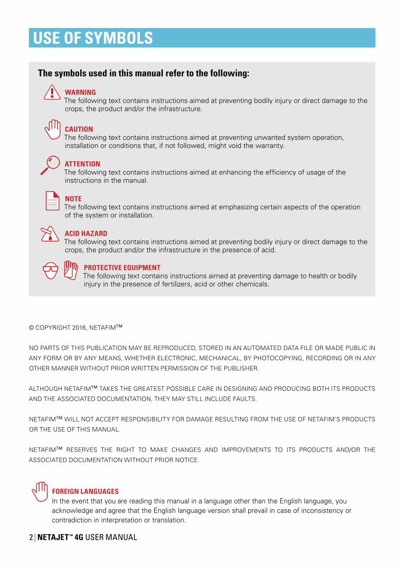
USE OF SYMBOLS
WARNINGThe following text contains instructions aimed at preventing bodily injury or direct damage to the crops, the product and/or the infrastructure.
CAUTIONThe following text contains instructions aimed at preventing unwanted system operation, installation or conditions that, if not followed, might void the warranty.
ATTENTIONThe following text contains instructions aimed at enhancing the efficiency of usage of the instructions in the manual.
NOTEThe following text contains instructions aimed at emphasizing certain aspects of the operation of the system or installation.
ACID HAZARDThe following text contains instructions aimed at preventing bodily injury or direct damage to the crops, the product and/or the infrastructure in the presence of acid.
The symbols used in this manual refer to the following:
PROTECTIVE EQUIPMENTThe following text contains instructions aimed at preventing damage to health or bodily injury in the presence of fertilizers, acid or other chemicals.

NETAJET ™ 4G USER MANUAL 3
45
666677888899
101214161820
222324
2526282929
303032
34
Safety Safety instructions When using acid/chemicals
Description Features Highlights Advantages Operating principle Main components Analog dosing channel Capabilities Service Maintenance Add-ons Modes Main parts of the NetaJet™ 4G and its infrastructure BP PL mode BP ST mode High-flow mode Octa - 8-channel mode IL PL mode IL ST mode
Operation and maintenance Operation Maintenance Winterization
Troubleshooting Symptoms regarding more than one single dosing channel Symptoms regarding a single dosing channel Symptoms while idle The NetaJet™ 4G does not function at all System vibrations
Dosing calibration 1. Calculation of dosing channels opening percentage 2. Simulation with a 10-liter (2-US-gallon) bucket of water 3. Calibration of the NetaJet™ 4G while irrigating
Warranty
CONTENTS

4 NETAJET ™ 4G USER MANUAL
SAFETY
Safety instructions• All safety regulations must be applied.
• Ensure that the installation is carried out in a manner that prevents leaks from the NetaJet™ 4G, the fertilizer/acid tanks and lines, the peripherals and the accessories (contaminating the environment, soil or ambient area).
• When using acid, always observe the acid manufacturer's safety instructions.
• Electrical installation and troubleshooting should be performed by an authorized electrician only.
• The electrical installation must comply with the local safety standards and regulations.
• Installation should be performed by authorized technicians only.
• Protection provided by the equipment can be impaired if the equipment is used in a manner other than that specified by the manufacturer.
CAUTIONRead the safety instructions before using, maintaining or troubleshooting the NetaJet™ 4G.
WARNINGIn agricultural environments - always wear protective footwear.
CAUTIONWhen opening or closing any manual valve, always do so gradually, to prevent damage to the system by water hammer.
WARNINGAlways use protective equipment, gloves and goggles when handling fertilizers, acid and other chemicals!
NOTEThe maximum sound level produced by the equipment does not exceed 70dB.
WARNINGMeasures must be taken to prevent fertilizer infiltration of the water source, to avoid water pollution.

NETAJET ™ 4G USER MANUAL 5
SAFETY
Safety instructions when using acid/chemicalsACID HAZARDWhen using acid - always observe the acid manufacturer's safety instructions.
WARNINGAlways use protective equipment, gloves and goggles when handling fertilizers, acid and other chemicals!
WARNINGExceeding the recommended acid concentrations will damage the dosing channels.
WARNINGSubstances such as chemicals for pest/disease control might be corrosive and damage the NetaJet™ 4G. When using any substance other than fertilizers or acids not exceeding the concentrations in the table above, always observe the manufacturer's instructions for corrosivity.In case of any doubt, contact your local Netafim™ representative.
ATTENTIONWhen dosing acid, use a dosing channel fitted with the appropriate components according tothe type and concentration of acid used*: For pH correction For maintenance of drippers
Type of dosing channel Diap
hrag
man
d O-
rings
Nitr
ic(H
NO
3)
Phos
phor
ic(H
3PO
4)
Sulfu
ric(H
2SO
4)
Hyd
roch
loric
(HC
l)
Hyd
roge
npe
roxi
de(H
2O2)
Chl
orin
e (a
shy
poch
lorid
e)
For diluted acid EPDM <3% <85% <30% <10% <30% <1%For concentrated acid Viton <40% <85% <90% <33% <50% <10%
% is by weight at 21oC (70oF)
*The table indicates the resistance of the dosing channel components to acid, and is not a recommendation to use the acids mentioned.
CAUTIONHigh concentrations of some fertilizer combinations might induce crystallization in the NetaJet's lower manifold and cause clogging of the pipes. These combinations should never be used in any concentration in the dual dosing channel (Octa mode only)!
Fertilizer combinations prone to induce crystallization:• Calcium nitrate + ammonium sulfate => calcium sulfate• Calcium nitrate + potassium sulfate => calcium sulfate• MKP + calcium nitrate => calcium phosphate• MAP + calcium nitrate => calcium phosphate• Phosphoric acid + calcium nitrate => calcium phosphate
When injecting these fertilizer combinations:• Make sure to dilute each fertilizer to the allowed concentration in the fertilizer tank prior to injection through the NetaJet™ 4G.• Immediately after each injection of any of the fertilizer combinations above, flush the NetaJet™ 4G with clean water for at least 2 minutes.
In case of doubt regarding the use of any combination of fertilizers, contact your local Netafim™ representative.

6 NETAJET ™ 4G USER MANUAL
DESCRIPTION
Features• The NetaJet™ 4G realizes Netafim’s “grow more with less” concept. Based on Netafim’s unique
Nutrigation™ technology, it controls the amount of water and fertilizers used, optimizing resource utilization for each specific crop and soil/substrate type.
• The NetaJet™ 4G is extremely accurate and reliable, preventing water and fertilizer waste while reducingenvironmental pollution.
• The NetaJet™ 4G ensures very precise and homogeneous nutrient dosing for greenhouse crops.• The NetaJet™ 4G is a modular CE-compliant dosing system that easily integrates with multiple
Netafim™ and third-party control and monitoring systems.• The NetaJet™ 4G always injects a uniform quantity of nutrients while performing perfect EC and pH control.• The NetaJet™ 4G can accommodate a wide variety of dosing channels for fertilizer and
concentrated/diluted acid.• The NetaJet™ 4G accommodates a wide variety of system pumps, peripherals and accessories to meet
a vast range of applications and infrastructure constraints.
Highlights• Equipped with Netafim's unique innovative
analog dosing channels for very accurate and reliable EC/pH control.
• Provides fast and accurate fertilizer and acid control.• State-of-the-art technology with unique static
mixing chamber• Short control cycle• Efficient water, fertilizer and energy consumption
• Guaranteed EC and pH control• Almost completely maintenance-free Venturi
operations – no moving parts• Highly accurate dosing channels• Fast and efficient Nutrigation™ recipe adjustments• Multi-lingual capabilities• Made by Netafim™
Advantages• Easy system installation and maintenance• In-house developed offering• Versatile flow capacity• Covers all applications ranging from greenhouse in soil, to very intensive soilless media• Requires minimal investment with rapid ROI
Operating principleThe NetaJet™ 4G doses the various fertilizers and acids into a homogeneous solution in its unique HidroMix static mixing chamber and injects it into the irrigation water main line.
The suction of the fertilizers and acid in the dosing channels is based on the Venturi principle. This requires a pressure differentiation - available on the main line or supplied by the main line pump or the NetaJet's dosing booster.
Main components• HydroMix static mixing chamber• A compensation channel with a pressure regulator• Factory-installed PRV at the inlet and a PSV at the
outlet• Selectable analog dosing channels• Dual EC/pH monitoring and control
• Quick-action dosing valves• Wide range of integrated accessories and
peripherals• High-quality components and PVC piping• Aluminum, corrosion-resistant frame with
adjustable legs

NETAJET ™ 4G USER MANUAL 7
DESCRIPTION
Analog dosing channelThe NetaJet™ 4G is the first fertilizer-dosing system equipped with Netafim's unique innovative analog dosing channel.
The analog dosing channel is the long-awaited solution for very accurate and reliable EC/pH control for Nutrigation™ of high-value greenhouse crops.
The analog dosing channel is equipped with a servo motor capable of continuous variable opening from 0 to 100%. This unique feature allows unprecedented precise and seamless Nutrigation™.
Advantages• Ultra-high precision• Smooth and stable hydraulic operation• No fluctuations• Fast EC/pH set-point reaching• Short stabilization time• Enables short Nutrigation™ cycles• No risk of cavitation damage to the booster
Stabilization timeThe analog dosing channel offers the benefit of asignificantly shorter stabilization time compared withthe digital (pulsating) dosing channel (up to 50%).This is particularly beneficial when performing shortNutrigation™ cycles typical of greenhouse crops.
• X = Analog (continuous-variable) dosing channel
• Y = Digital (pulsating) dosing channel
Dual dosing channelThe NetaJet™ 4G Octa mode (8 dosing channels) includes 3 dual dosing channel.The dual dosing channel is applicable with 50 l/h (13 GPH) and 600 l/h (158 GPH) Venturis.
Dual dosing channel schematic diagram
pH
Time (sec)
109876543210
2050
X
Y
Source water
352510 403015 45 50
Analog (continuous-variable) dosing channelDigital (pulsating) dosing channelpH set point
Digital (ON/OFF) vs. analog dosing channel performances
A RotameterB Needle valveC Dosing valveD Check valveE Venturi
A
BCDE
A
BCDE
CAUTIONThere are fertilizer combinations that should never be used in any concentration in the dual dosing channel! (see CAUTION, page 5)
8 NETAJET ™ 4G USER MANUAL
DESCRIPTION
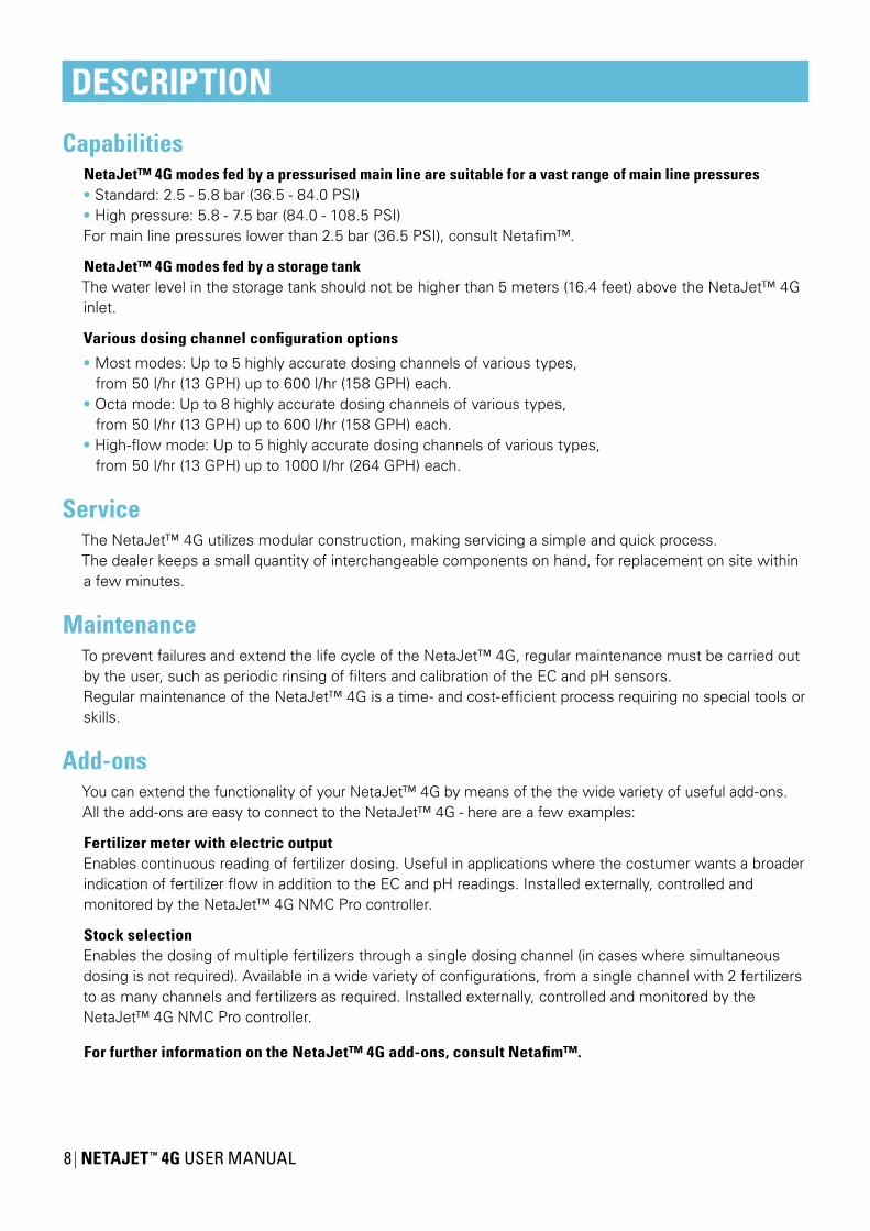
CapabilitiesNetaJet™ 4G modes fed by a pressurised main line are suitable for a vast range of main line pressures• Standard: 2.5 - 5.8 bar (36.5 - 84.0 PSI)• High pressure: 5.8 - 7.5 bar (84.0 - 108.5 PSI)For main line pressures lower than 2.5 bar (36.5 PSI), consult Netafim™.
NetaJet™ 4G modes fed by a storage tankThe water level in the storage tank should not be higher than 5 meters (16.4 feet) above the NetaJet™ 4G inlet.
Various dosing channel configuration options
• Most modes: Up to 5 highly accurate dosing channels of various types,from 50 l/hr (13 GPH) up to 600 l/hr (158 GPH) each.
• Octa mode: Up to 8 highly accurate dosing channels of various types,from 50 l/hr (13 GPH) up to 600 l/hr (158 GPH) each.
• High-flow mode: Up to 5 highly accurate dosing channels of various types,from 50 l/hr (13 GPH) up to 1000 l/hr (264 GPH) each.
ServiceThe NetaJet™ 4G utilizes modular construction, making servicing a simple and quick process.The dealer keeps a small quantity of interchangeable components on hand, for replacement on site within a few minutes.
MaintenanceTo prevent failures and extend the life cycle of the NetaJet™ 4G, regular maintenance must be carried out by the user, such as periodic rinsing of filters and calibration of the EC and pH sensors.Regular maintenance of the NetaJet™ 4G is a time- and cost-efficient process requiring no special tools or skills.
Add-onsYou can extend the functionality of your NetaJet™ 4G by means of the the wide variety of useful add-ons. All the add-ons are easy to connect to the NetaJet™ 4G - here are a few examples:
Fertilizer meter with electric outputEnables continuous reading of fertilizer dosing. Useful in applications where the costumer wants a broader indication of fertilizer flow in addition to the EC and pH readings. Installed externally, controlled and monitored by the NetaJet™ 4G NMC Pro controller.
Stock selectionEnables the dosing of multiple fertilizers through a single dosing channel (in cases where simultaneous dosing is not required). Available in a wide variety of configurations, from a single channel with 2 fertilizers to as many channels and fertilizers as required. Installed externally, controlled and monitored by the NetaJet™ 4G NMC Pro controller.
For further information on the NetaJet™ 4G add-ons, consult Netafim™.

NETAJET ™ 4G USER MANUAL 9
DESCRIPTION
Modes• BP PL: Bypass system for pressurized-line water source; 5 dosing channels (see page 10)
• BP ST: Bypass system for storage-tank water source; 5 dosing channels (see page 12)
• High-flow: High-flow bypass system for pressurized-line water source; 5 dosing channels (see page 14)
• Octa - 8-channel: Bypass system for pressurized-line water source; 6-8 dosing channels (see page 16)
• IL PL: Inline system for pressurized-line water source; 5 dosing channels (see page 18)
• IL ST: Inline system for storage-tank water source; 5 dosing channels (see page 20)
Legend:
BP BypassIL InlinePL Pressurized lineST Storage tank
Main parts of the NetaJet™ 4G and its infrastructureThe list below presents the main parts of the NetaJet™ 4G and the parts of the infrastructure required for the operation of the NetaJet™ 4G various modes.
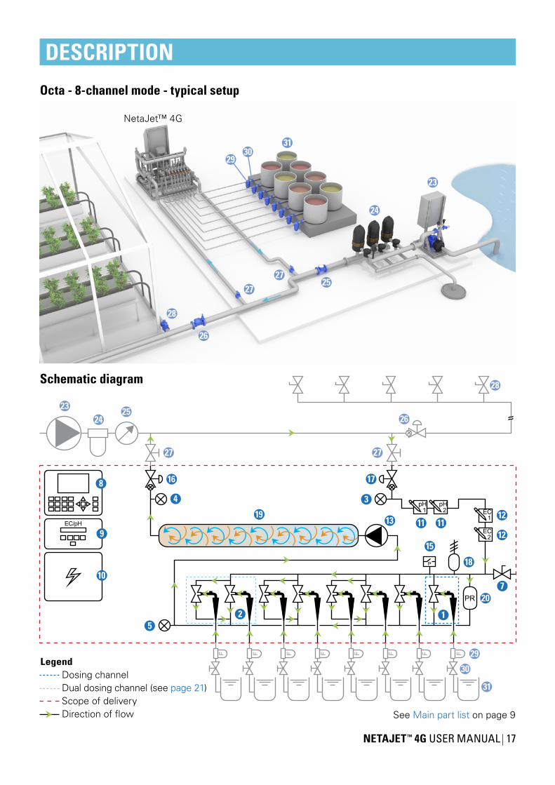
1 Dosing channel + Venturi2 Dual dosing channel + Venturis3 Inlet pressure gauge4 Outlet pressure gauge5 Lower manifold pressure gauge6 Main line pressure gauge7 Sampling outlet8 Controller9 EC/pH transducer
10 Dosing booster switchbox11 pH sensor
12 EC sensor13 Dosing booster14 Check valve15 Pressure switch16 Pressure sustaining valve (PSV)17 Pressure reducing valve (PRV)18 Air release valve19 Mixing chamber20 Compensation channel21 Onboard main line pump22 Upper manifold filter
23 Main line pump24 Main line filter25 Main line water meter
26 Main line pressure sustaining valve (PSV)27 Manual valve (isolation)28 Irrigation valve29 Fertilizer/acid filter30 Manual valve (fertilizer)31 Fertilizer/acid stock tank
Color code: Supplied (part of the NetaJet™ 4G) Not supplied (part of infrastructure).

10 NETAJET ™ 4G USER MANUAL
DESCRIPTION
BP PL modeBypass system for pressurized-line water source.
Operating principle:The pressure differential required to generate fertilizer suction via the Venturis is produced by a booster pump integrated in the NetaJet™ 4G. This mode of operation, where the lower manifold is under low pressure (around 0 bar/PSI), permits the use of high-efficiency Venturis with high suction capacity and low motive flow consumption.
Suitable for main line flow rate:20-120 m³/h (90-500 GPM)Flow limitation depends on the fertilizer injection rate and the size of the Venturis.
Suitable for main line pressure:Standard: 2.5-5.8 bar (36.5-84.0 PSI)High pressure: 5.8-7.5 bar (84.0-108.5 PSI)For main line pressures lower than 2.5 bar (36.5 PSI), consult Netafim™.
Dosing channels:Accommodates a wide variety of highly accurate dosing channels for fertilizer and concentrated/diluted acid:• Up to 5 dosing channels of various types, from 50 l/hr (13 GPH) up to 600 l/hr (158 GPH) each.• Optional - Concentrated acid channel, 50 l/h (13 GPH).Total fertilizer/acid suction capacity - up to 3000 l/h (792 GPH).
Controller:NMC-Pro (Operation with third-party controllers is optional. Consult Netafim™.)
EC/pH:Dual (single is optional), monitoring and control.
Front view Back view

NETAJET ™ 4G USER MANUAL 11
DESCRIPTION
Dosing channelScope of deliveryDirection of flow
Legend
1
34
5
7
8
9
10
11 1112
12
13
15
16 17
18
19
20
2324
2526
27 27
28
2930 31
See Main part list on page 9
BP PL mode - typical setup
Schematic diagram
23
24
25
26
27
28
31
27
NetaJet™ 4G
3029

12 NETAJET ™ 4G USER MANUAL
DESCRIPTION
BP ST modeBypass system for storage-tank water source.
Operating principle:For systems operating at low pressure - from an on-ground reservoir or a storage tank [max. height: 6 meters (20 feet)].The main line pump also serves as dosing booster pump.
Suitable for main line flow rate:15-100 m³/h (66-440 GPM)Flow limitation depends on the fertilizer injection rate and the size of the Venturis.
Suitable for main line pressure:The water level in the storage tank should not be higher than 5 meters (16.4 feet) above the NetaJet™ 4G inlet.
Dosing channels:Accommodates a wide variety of highly accurate dosing channels for fertilizer and concentrated/diluted acid:• Up to 5 x 50-600 l/hr (13-158 GPH)• Optional - Concentrated acid channel, 50 l/h (13 GPH)Total fertilizer/acid suction capacity - up to 3000 l/h (792 GPH).
Controller:NMC-Pro (Operation with third-party controllers is optional. Consult Netafim™.)
EC/pH:Dual (single is optional), monitoring and control.
Front view Back view

NETAJET ™ 4G USER MANUAL 13
DESCRIPTION
See Main part list on page 9
1
3
5
7
8
9
10
11 1112
12
17
18
19
20
2324
2526
27 27
28
2930 31
Dosing channelScope of deliveryDirection of flow
Legend
22
14
BP ST mode - typical setup
Schematic diagram
NetaJet™ 4G
23
24
2526
27
28
31
27
3029
14 NETAJET ™ 4G USER MANUAL
DESCRIPTION
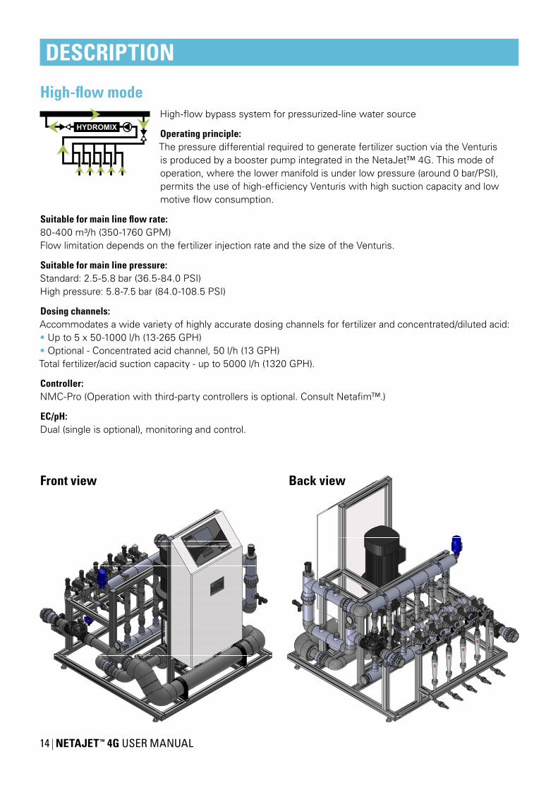
High-flow modeHigh-flow bypass system for pressurized-line water source
Operating principle:The pressure differential required to generate fertilizer suction via the Venturis is produced by a booster pump integrated in the NetaJet™ 4G. This mode of operation, where the lower manifold is under low pressure (around 0 bar/PSI), permits the use of high-efficiency Venturis with high suction capacity and low motive flow consumption.
Suitable for main line flow rate:80-400 m³/h (350-1760 GPM)Flow limitation depends on the fertilizer injection rate and the size of the Venturis.
Suitable for main line pressure:Standard: 2.5-5.8 bar (36.5-84.0 PSI)High pressure: 5.8-7.5 bar (84.0-108.5 PSI)
Dosing channels:Accommodates a wide variety of highly accurate dosing channels for fertilizer and concentrated/diluted acid:• Up to 5 x 50-1000 l/h (13-265 GPH)• Optional - Concentrated acid channel, 50 l/h (13 GPH)Total fertilizer/acid suction capacity - up to 5000 l/h (1320 GPH).
Controller:NMC-Pro (Operation with third-party controllers is optional. Consult Netafim™.)
EC/pH:Dual (single is optional), monitoring and control.
Front view Back view

NETAJET ™ 4G USER MANUAL 15
DESCRIPTION
1
34
5
7
8
9
10
11 1112
1213
15
16 17
18
19
20
2324
25
27 27
28
2930 31
26
Dosing channelScope of deliveryDirection of flow
Legend
See Main part list on page 9
High-flow mode - typical setup
Schematic diagram
NetaJet™ 4G
23
24
25
26
27
28
31
27
3029

16 NETAJET ™ 4G USER MANUAL
DESCRIPTION
Octa - 8-channel modeBypass system for pressurized-line water source, with 8 dosing channels.
Operating principle:The pressure differential required to generate fertilizer suction via the Venturis isproduced by a booster pump integrated in the NetaJet™ 4G. This mode of operation,where the lower manifold is under low pressure (around 0 bar/PSI), permits the useof high-efficiency Venturis with high suction capacity and low motive flow consumption.
Suitable for main line flow rate:20-120 m³/h (90-500 GPM). Flow limitation depends on the fertilizer injection rate and the size of the Venturis.
Suitable for main line pressure:Standard: 2.5-5.8 bar (36.5-84.0 PSI)High pressure: 5.8-7.5 bar (84.0-108.5 PSI)
Dosing channels:Accommodates a wide variety of highly accurate dosing channels for fertilizer and concentrated/diluted acid:• Up to 8 x 50-600 l/h (13-158 GPH)• Optional - Concentrated acid channel, 50 l/h (13 GPH)Total fertilizer/acid suction capacity - up to 4800 l/h (1268 GPH).
CAUTIONThe Octa mode (8 dosing channels) includes 3 dual dosing channels. There are fertilizer combinations that should never be used in any concentration in the dual dosing channel! (see CAUTION, page 5)
Controller:NMC-Pro (Operation with third-party controllers is optional. Consult Netafim™.)
EC/pH:Dual (single is optional), monitoring and control.
Front view Back view
NETAJET ™ 4G USER MANUAL 17
DESCRIPTION
12
34
5
7
8
9
10
11 1112
12
13
15
16 17
18
19
20
2324
2526
27 27
28
29
30
31
See Main part list on page 9
Dosing channelDual dosing channel (see page 21)Scope of deliveryDirection of flow
Legend
Octa - 8-channel mode - typical setup
Schematic diagram
NetaJet™ 4G
23
24
25
26
27
28
31
27
3029

18 NETAJET ™ 4G USER MANUAL
DESCRIPTION
IL PL modeInline system for pressurized line water source
Operating principle:The pressure differential required to generate fertilizer suction via the Venturis is produced by a booster pump integrated in the NetaJet™ 4G. This mode of operation, where the lower manifold is at low pressure (around 0 bar/psi), allows
the use of high-efficiency Venturis with high suction capacity and low motive flow consumption.Since all the main line water flows through the system, slight pressure losses at the NetaJet™ 4G outlet should be considered (see the table below).
Suitable for main line flow rate:Up to 20 m³/h (90 GPM)
Suitable for main line pressure:Standard: 2.5-5.8 bar (36.5-84.0 PSI)High pressure: 5.8-7.5 bar (84.0-108.5 PSI)
Dosing channels:Accommodates a wide variety of highly accurate dosing channels for fertilizer and concentrated/diluted acid:• Up to 5 x 50-400 l/hr (13-105.5 GPH)• Optional - Concentrated acid channel, 50 l/h (13 GPH)Total fertilizer/acid suction capacity - up to 2000 l/h (528 GPH).
Controller:NMC-Pro (Operation with third-party controllers is optional. Consult Netafim™.)
EC/pH:Dual (single is optional), monitoring and control.
Front view Back view
Flow ratem³/h (GPM)
Pressure lossbar (PSI)
5 (22) 0.3 (4.35)10 -20 (44-88) 0.4 (5.8)
Pressure losses

NETAJET ™ 4G USER MANUAL 19
DESCRIPTION
1
34
5
6
7
8
9
10
11 1112
1213
14
16 17
18
19
20
2324
25
26
28
2930 31
Dosing channelScope of deliveryDirection of flow
Legend
See Main part list on page 9
IL PL mode - typical setup
Schematic diagram
NetaJet™ 4G
23
24
25
26
28
313029

20 NETAJET ™ 4G USER MANUAL
DESCRIPTION
IL ST modeInline system for storage-tank water source
Operating principle:The pressure differential required to generate fertilizer suction via the Venturis is produced by a booster pump integrated in the NetaJet™ 4G. This mode of operation, where the lower manifold is at low pressure (around 0 bar/psi), allows
the use of high-efficiency Venturis with high suction capacity and low motive flow consumption.Since all the main line water flows through the system, slight pressure losses at the NetaJet™ 4G outlet should be considered (see the table below).
Suitable for main line flow rate:Up to 20 m³/h (90 GPM)
Suitable for main line pressure:The water level in the storage tank should not be higher than5 meters (16.4 feet) above the NetaJet™ 4G inlet.
Dosing channels:Accommodates a wide variety of highly accurate dosing channels for fertilizer and concentrated/diluted acid:• Up to 5 x 50-400 l/hr (13-105.5 GPH)• Optional - Concentrated acid channel, 50 l/h (13 GPH)Total fertilizer/acid suction capacity - up to 2000 l/h (528 GPH).
Controller:NMC-Pro (Operation with third-party controllers is optional. Consult Netafim™.)
EC/pH:Dual (single is optional), monitoring and control.
Front view Back view
Flow ratem³/h (GPM)
Pressure lossbar (PSI)
5 (22) 0.8 (11.6)10 (44) 0.9 (13.05)
15-20 (66-88) 1.0 (14.5)
Pressure losses

NETAJET ™ 4G USER MANUAL 21
DESCRIPTION
1
34
6
7
8
9
10
11 1112
12
14
17
18
19
20
21
24
2526
28
2930 31
See Main part list on page 9
Dosing channelScope of deliveryDirection of flow
Legend
22
IL ST mode - typical setup
Schematic diagram
NetaJet™ 4G
3029
24
2526
28
31

22 NETAJET ™ 4G USER MANUAL
OPERATION AND MAINTENANCE
OperationThe routine operation of the NetaJet™ 4G is almost totally automatic, controlled by the controller(for the operation of the controller, see the Controller Manual).
All you need is to make sure that:
• Electricity is supplied to the NetaJet™ 4G.
• Adequate quality water at the appropriate flow rate and pressure is supplied at the inlet of the NetaJet™ 4G (see NetaJet™ 4G Hydraulic Conditions Checklist).
• Fertilizers that are dissolved properly, according to the agronomist's instructions, are constantly present in the stock tanks.
• If acid is used - it is constantly present in the acid stock tank and does not exceed the recommended concentration (see ATTENTION, page 5).
Dual dosing channelThe NetaJet™ 4G Octa mode (8 dosing channels) includes 3 dual dosing channels.The dual dosing channels are applicable with 50 l/h (13 GPH) and 600 l/h (158 GPH) Venturis.
CAUTIONThere are fertilizer combinations that should never be used in any concentration in the dual dosing channel! (see CAUTION, page 5)
NETAJET ™ 4G USER MANUAL 23
OPERATION AND MAINTENANCE
Maintenance
CAUTIONWhen opening or closing any manual valve, always do so gradually, to prevent damage to the system by water hammer.
To prevent failures and extend the life cycle of the NetaJet™ 4G, the user must carry out regular maintenance.
• Keep the NetaJet™ 4G dosing unit and its immediate environment clean and dry.
CAUTIONBefore calibrating the EC and pH sensors, gradually close the isolation valves and open the sampling outlet until the pressure in the system is released.
• The NetaJet™ 4G dosing unit and the supply water and irrigation system must be inspected regularly.
Regular inspection
Description How often InstructionsRinsing of fertilizer filters* Once a dayRinsing of supply water filters* Once a dayWater and fertilizer leak inspection Once a week Visual inspectionCalibration of the pH sensor Every 2-4 weeks
See the EC/pH Transducer ManualCalibration of the EC sensor Every 4 weeks
* Manual filters only.
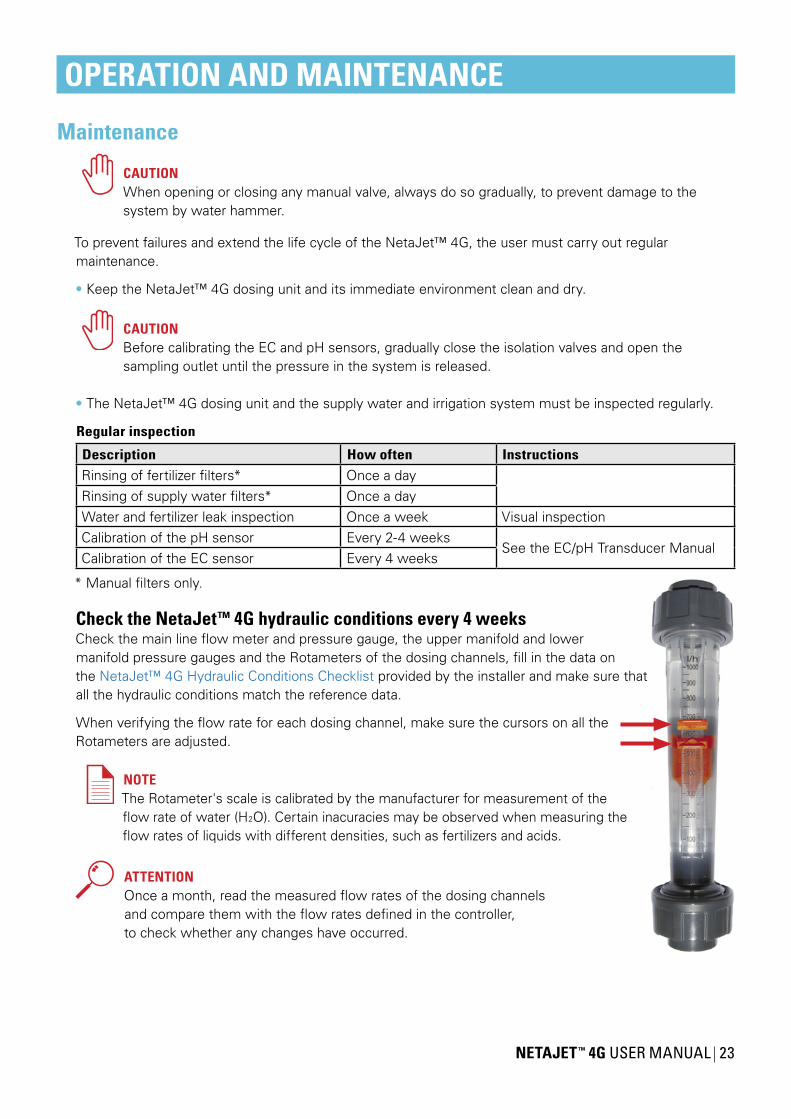
Check the NetaJet™ 4G hydraulic conditions every 4 weeksCheck the main line flow meter and pressure gauge, the upper manifold and lowermanifold pressure gauges and the Rotameters of the dosing channels, fill in the data onthe NetaJet™ 4G Hydraulic Conditions Checklist provided by the installer and make sure thatall the hydraulic conditions match the reference data.
When verifying the flow rate for each dosing channel, make sure the cursors on all the Rotameters are adjusted.
NOTEThe Rotameter's scale is calibrated by the manufacturer for measurement of theflow rate of water (H2O). Certain inacuracies may be observed when measuring theflow rates of liquids with different densities, such as fertilizers and acids.
ATTENTIONOnce a month, read the measured flow rates of the dosing channelsand compare them with the flow rates defined in the controller,to check whether any changes have occurred.
24 NETAJET ™ 4G USER MANUAL
OPERATION AND MAINTENANCE
Winterization
CAUTIONWhen opening or closing any manual valve, always do so gradually, to prevent damage to the system by water hammer.
In areas susceptible to freezing temperatures, if the system is not required for irrigation during the winter, perform the following procedure to avoid damage caused by freezing when the NetaJet™ 4G is idle for the winter period:
At the beginning of winter:• Gradually close the isolation valves and open the sampling valve until the pressure in the system is released.• Remove EC and pH sensors and store the pH sensor immersed in KCL solution (supplied with the sensor) or in calibration buffer 4 at a temperature of 18-25˚C (64-77˚F). The pH sensor must never be dry (see EC/pH Transducer Manual).• Empty the NetaJet™ 4G of water.
At the end of winter:• Reinstall the EC and pH sensors and calibrate them (see EC/pH Transducer Manual).• Gradually open the isolation valves until the pressure in the system is restored.

NETAJET ™ 4G USER MANUAL 25
TROUBLESHOOTINGThis chapter is a systematic guide to the actions to be taken in the case of a malfunction of the NetaJet™ 4G.
ATTENTIONBefore proceeding to troubleshoot any malfunction, make sure that:• The controller settings regarding the dosing channels are correct and match the dosing channels of the NetaJet™ 4G (see the Controller Manual).• The controller settings regarding the irrigation valves are correct (see the Controller Manual).
Perform the actions in their order of appearance until the malfunction is fixed.If you identify faulty parts - consult your Netafim™ representative.
CAUTIONOnly qualified electricians are permitted to perform electrical installations and repairs!
CAUTIONIf isolation valves have been installed on the system, ensure that they are in closed position before troubleshooting any hydraulic malfunction.
ATTENTIONIf fertilizers from a different manufacturer have been recently in use and changes in EC and pH are recorded, perform calibration of the system before assuming a malfunction of the NetaJet™ 4G(see Dosing calibration, page 30).
Symptoms regarding more than one single dosing channelIf one or more of the following symptoms occur regarding more than one single dosing channel,perform the actions listed below:
Controller warnings• Low EC• High pH• Low fertilizer/acid flow rate
Rotameter reading• Low fertilizer/acid flow rate
Action1) For controller warnings only - check and calibrate the EC and pH sensors (see the EC/pH Transducer Manual).
2) Have a qualified electrician check that electricity is being supplied to the NetaJet™ 4G and that all the electrical components are properly connected (see the Switchboard Diagram).
3) Check that the hydraulic conditions comply with the reference data in the NetaJet™ 4G Hydraulic Conditions Checklist.
If NO, restore the original hydraulic conditions according to the reference data in the NetaJet™ 4G Hydraulic Conditions Checklist.
If YES or if the malfunction is still not fixed after restoring the original hydraulic conditions, in modes with a dosing booster - have a qualified electrician check the dosing booster: Does it function? Does it rotate in the correct direction? If not - the electrician should swap between phases L1 and L3 (see the Dosing Booster Manual).

26 NETAJET ™ 4G USER MANUAL
4) Check for an air pocket in the dosing booster impeller chamber (see the Dosing Booster Manual): Open the NetaJet™ 4G sampling outlet until a stable flow, free of air-bubbles, is obtained.
5) If the original hydraulic conditions are still not restored - loosen the dosing booster's bleeding screw and wait until a stable flow, free of air-bubbles, is obtained, then retighten the bleeding screw (see the Dosing Booster Manual).
6) Check the dosing booster's impeller chamber for clogging: If it is clogged - it should be dismantled and thoroughly cleaned (see the Dosing Booster Manual).
If after implementing all the above steps the malfunction is still not fixed - consult your Netafim™ representative.
Symptoms regarding a single dosing channel
TROUBLESHOOTING
A
B
CD
Analog dosing channel Digital dosing channel
H
G
E
FA
H
G
E
FD
Analog dosing valve Digital dosing valveOPEN
Manual operationAUTO
Controlled operationOPEN
Manual operationCLOSE
Controlled operation
OPEN CLOSEOPEN CLOSE
OPEN
AUTO
OPEN
AUTO
NETAJET ™ 4G USER MANUAL 27
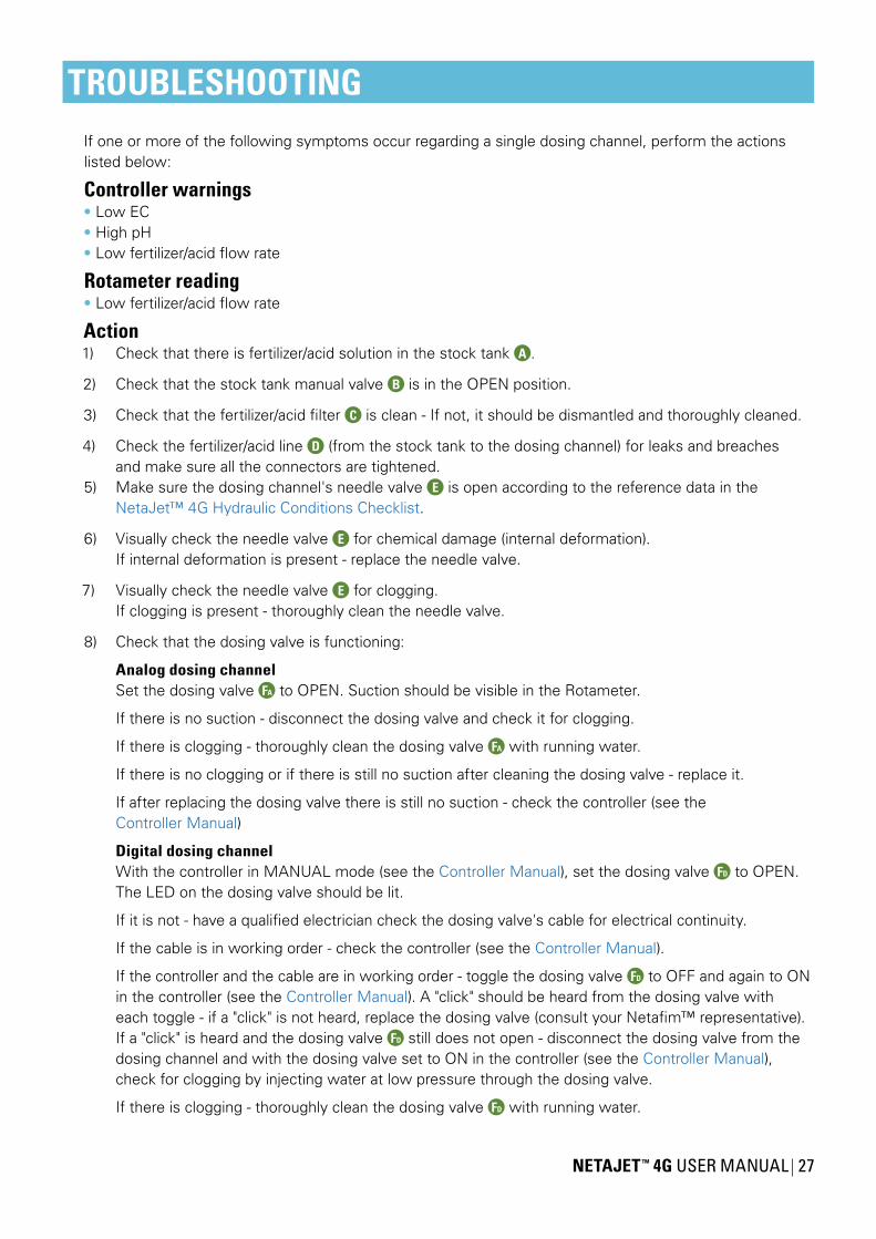
TROUBLESHOOTINGIf one or more of the following symptoms occur regarding a single dosing channel, perform the actions listed below:
Controller warnings• Low EC• High pH• Low fertilizer/acid flow rate
Rotameter reading• Low fertilizer/acid flow rate
Action1) Check that there is fertilizer/acid solution in the stock tank A .
2) Check that the stock tank manual valve B is in the OPEN position.
3) Check that the fertilizer/acid filter C is clean - If not, it should be dismantled and thoroughly cleaned.
4) Check the fertilizer/acid line D (from the stock tank to the dosing channel) for leaks and breaches and make sure all the connectors are tightened.5) Make sure the dosing channel's needle valve E is open according to the reference data in the NetaJet™ 4G Hydraulic Conditions Checklist.
6) Visually check the needle valve E for chemical damage (internal deformation). If internal deformation is present - replace the needle valve.
7) Visually check the needle valve E for clogging. If clogging is present - thoroughly clean the needle valve.
8) Check that the dosing valve is functioning:
Analog dosing channel Set the dosing valve FA to OPEN. Suction should be visible in the Rotameter.
If there is no suction - disconnect the dosing valve and check it for clogging.
If there is clogging - thoroughly clean the dosing valve FA with running water.
If there is no clogging or if there is still no suction after cleaning the dosing valve - replace it.
If after replacing the dosing valve there is still no suction - check the controller (see the Controller Manual)
Digital dosing channel With the controller in MANUAL mode (see the Controller Manual), set the dosing valve FD to OPEN. The LED on the dosing valve should be lit.
If it is not - have a qualified electrician check the dosing valve's cable for electrical continuity.
If the cable is in working order - check the controller (see the Controller Manual).
If the controller and the cable are in working order - toggle the dosing valve FD to OFF and again to ON in the controller (see the Controller Manual). A "click" should be heard from the dosing valve with each toggle - if a "click" is not heard, replace the dosing valve (consult your Netafim™ representative). If a "click" is heard and the dosing valve FD still does not open - disconnect the dosing valve from the dosing channel and with the dosing valve set to ON in the controller (see the Controller Manual), check for clogging by injecting water at low pressure through the dosing valve.
If there is clogging - thoroughly clean the dosing valve FD with running water.

28 NETAJET ™ 4G USER MANUAL
TROUBLESHOOTING
If there is no clogging but the dosing valve FD still does not open - replace it (consult your Netafim™ representative).
9) Visually check the non-return valve G for any internal deformation or damage to its flat ring gasket. If present - replace the non-return valve (consult your Netafim™ representative).
10) Check the non-return valve G for clogging by injecting water at low pressure through it (make sure to respect the direction of flow).
If there is clogging - thoroughly clean the non-return valve G with running water.
11) Disconnect the Venturi H from the manifolds and from the dosing channel and check it for clogging, visually and by injecting water through it at low pressure.
If there is clogging - thoroughly clean the Venturi H with running water.
12) Visually check the Venturi H for chemical damage (internal deformation). If internal deformation is present - replace the Venturi (consult your Netafim™ representative).
If after implementing all the above steps the malfunction is still not fixed - consult your Netafim™ representative.
Symptoms while idleIf the following symptoms occur while the NetaJet™ 4G is idle, perform the actions listed below:
Controller warnings• High EC• Low pH• While idle - Uncontrolled fertilizer/acid flow rate or a fertilizer/acid leak or breach
Action
NOTE• When using an analog dosing valve, make sure the dosing valve selector is in the AUTO position.• When using a digital dosing valve (S22), make sure the dosing valve selector is in the CLOSED
position.
Check if the dosing valves leak when closed:
1) Close all the manual valves B for fertilizers and acid.
2) Make sure the level of the solution in all the the stock tanks is higher than the dosing valves.
3) With the controller in MANUAL mode, set all the dosing valves to OFF (see the Controller Manual).
4) Disconnect one of the the dosing valves from the non-return valve (downstream from the dosing valve).
5) Open the fertilizer manual valve B .
If a leak from the dosing valve is visible - disconnect the dosing valve from the dosing channel.6) With the controller in MANUAL mode, set the dosing valve to ON (see the Controller Manual).
7) Thoroughly clean the dosing valve with running water.
8) Repeat steps 4-7 for each fertilizer and acid dosing channel.

NETAJET ™ 4G USER MANUAL 29
9) After completing the procedure, open all the manual valves B for fertilizers and acids.
10) If the malfunction is still not fixed - replace the dosing valve.
If after implementing all the above steps the malfunction is still not fixed - consult your Netafim™ representative.
The NetaJet™ 4G does not function at all
CAUTIONOnly qualified electricians are permitted to perform electrical installations and repairs!
If the following symptom occurs, perform the actions listed below:
SymptomThe NetaJet™ 4G does not function.
Action1) Have a qualified electrician check the overload protection breaker (see the Switchboard Diagram):
If it is not in the ON position, turn it to ON.
If it is in the ON position, toggle it once to OFF and to ON again (do not repeat this action).
If the overload protection breaker trips (turns to OFF or to TRIP) again, the electrician will check whether the system pump is in working order (see the system pump manual) and check for irregularities in the electricity voltage supplied to the NetaJet™ 4G.
If after implementing all the above steps the malfunction is still not fixed - consult your Netafim™ representative.
System vibrationsIf the following symptom occurs during operation, perform the action listed below:
SymptomThe NetaJet™ 4G vibrates during operation.
CauseThe main line pressure is out of the NetaJet™ 4G working range (higher or lower).
Action1) Restore the main line pressure to the original value according to the reference data in the NetaJet™ 4G Hydraulic Conditions Checklist.
If the main line pressure is restored and the vibrations persist - consult your Netafim™ representative.
2) If it is impossible to restore the main line pressure according to the reference data - alter the system calibration according to the actual main line pressure - consult your Netafim™ representative.
TROUBLESHOOTING
ON OFFTRIP
30 NETAJET ™ 4G USER MANUAL
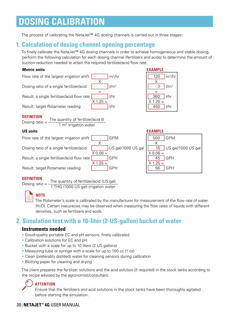
DOSING CALIBRATIONThe process of calibrating the NetaJet™ 4G dosing channels is carried out in three stages:
1. Calculation of dosing channel opening percentageTo finely calibrate the NetaJet™ 4G dosing channels in order to achieve homogeneous and stable dosing, perform the following calculation for each dosing channel (fertilizers and acids) to determine the amount of suction reduction needed to attain the required fertilizer/acid flow rate.
Flow rate of the largest irrigation shift
Dosing ratio of a single fertilizer/acid
Result: a single fertilizer/acid flow rate
Result: target Rotameter reading
EXAMPLE
=
Xm3/hr
l/m3
l/hr
l/hrX 1.25 =
120
3
360
450
Metric units
EXAMPLE
X 0.06 =
XGPM
US gal/1000 US gal
GPH
GPHX 1.25 =
500
15
45
56
US units
X 0.06 =
XGPM
US gal/1000 US gal
GPH
GPHX 1.25 =
=
Xm3/hr
l/m3
l/hr
l/hrX 1.25 =
Flow rate of the largest irrigation shift
Dosing ratio of a single fertilizer/acid
Result: a single fertilizer/acid flow rate
Result: target Rotameter reading
DEFINITIONDosing ratio =
The quantity of fertilizer/acid (l)1 m3 irrigation water
DEFINITIONDosing ratio =
The quantity of fertilizer/acid (US gal)1 THG (1000 US gal) irrigation water
NOTEThe Rotameter's scale is calibrated by the manufacturer for measurement of the flow rate of water (H2O). Certain inacuracies may be observed when measuring the flow rates of liquids with different densities, such as fertilizers and acids.
2. Simulation test with a 10-liter (2-US-gallon) bucket of waterInstruments needed• Good-quality portable EC and pH sensors, finely calibrated• Calibration solutions for EC and pH• Bucket with a scale for up to 10 liters (2 US gallons) • Measuring tube or syringe with a scale for up to 100 cc (1 oz)• Clean (preferably distilled) water for cleaning sensors during calibration• Blotting paper for cleaning and drying
The client prepares the fertilizer solutions and the acid solution (if required) in the stock tanks according to the recipe advised by the agronomist/consultant.
ATTENTIONEnsure that the fertilizers and acid solutions in the stock tanks have been thoroughly agitated before starting the simulation.
NETAJET ™ 4G USER MANUAL 31
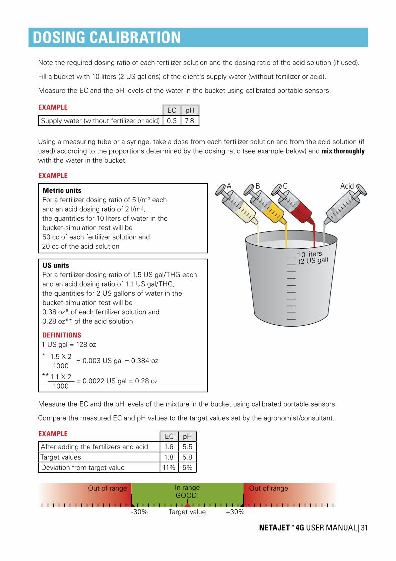
DOSING CALIBRATIONNote the required dosing ratio of each fertilizer solution and the dosing ratio of the acid solution (if used).
Fill a bucket with 10 liters (2 US gallons) of the client's supply water (without fertilizer or acid).
Measure the EC and the pH levels of the water in the bucket using calibrated portable sensors.
EC pHSupply water (without fertilizer or acid) 0.3 7.8
Using a measuring tube or a syringe, take a dose from each fertilizer solution and from the acid solution (if used) according to the proportions determined by the dosing ratio (see example below) and mix thoroughly with the water in the bucket.
10 liters(2 US gal)
A B C AcidMetric unitsFor a fertilizer dosing ratio of 5 l/m3 eachand an acid dosing ratio of 2 l/m3,the quantities for 10 liters of water in thebucket-simulation test will be50 cc of each fertilizer solution and20 cc of the acid solution
EXAMPLE
US unitsFor a fertilizer dosing ratio of 1.5 US gal/THG eachand an acid dosing ratio of 1.1 US gal/THG,the quantities for 2 US gallons of water in thebucket-simulation test will be0.38 oz* of each fertilizer solution and0.28 oz** of the acid solution
DEFINITIONS1 US gal = 128 oz
* 1.5 X 21000
= 0.003 US gal = 0.384 oz
** 1.1 X 21000
= 0.0022 US gal = 0.28 oz
Measure the EC and the pH levels of the mixture in the bucket using calibrated portable sensors.
Compare the measured EC and pH values to the target values set by the agronomist/consultant.
EC pHAfter adding the fertilizers and acid 1.6 5.5Target values 1.8 5.8Deviation from target value 11% 5%
Target value +30%-30%
In rangeGOOD!
Out of range Out of range
EXAMPLE
EXAMPLE

32 NETAJET ™ 4G USER MANUAL
DOSING CALIBRATIONWith the controller set to operate according to EC/pH values - if the EC and pH values measured in the bucketare within a range of ±30% deviation from the target values, the system will be able to correct them automatically.
If the values are out of the ±30% range, check the data and consult the agronomist/consultant.
3. Calibration of the NetaJet™ 4G while irrigating
WARNINGExtreme EC or pH values may damage the crop.Perform the following procedure only after completing stage 2 above (Simulation test with a 10-liter or 2-US-gallon bucket of water) with satisfactory results.
NOTEThe following steps explain the operations to be performed, regardless of the type of controller used. For the operation of your controller's interface, consult the Controller Manual.However, since the NMC Pro controller is widely used - its interface screens for the execution of each step are noted.
NOTEBefore the calibration, confirm that the EC and the pH sensors of the NetaJet™ 4G have been calibrated according to the instructions in the EC/pH Installation Manual.
Define the dosing configuration, while the EC and pH controls are in the OFF position (NMC Pro - screen 7.7).
In the EC and pH alarm definitions, set the EC and pH alarm to the OFF position (deactivated)(NMC Pro - screen 3.6).
Enter the data for the irrigation valves, and the dosing ratio for each dosing channel(NMC Pro - screens 1.1-1.2-1.3).
Run the program (NMC Pro - screen 2.2).
Allow a few minutes for the pipes to fill up and the flow rate to stabilize.
Reduce the suction of the dosing channels by adjusting the manual needle valve of each dosing channel until the "target Rotameter reading" calculated in stage 1 (page 30) is attained.
NOTEThe Rotameter's scale is calibrated by the manufacturer for measurement of the flow rate of water (H2O). Certain inacuracies may be observed when measuring the flow rates of liquids with different densities, such as fertilizers and acids.
Check the appropriate controller screen for the measured EC and pH values (NMC Pro - hot screen 4).If the desired values have been reached, check opening percentages of the dosing valves.
The EC and pH target values should be attained with the dosing valves opened to 50% - 80% of their capacity.
If the EC and pH target values are attained with the dosing valves opened less than 50%, reduce the dosing channel suction rate, until the EC and pH target values are reached.
NOTEEvery change in the flow rate of the needle valve must be updated afterwards in the controller (NMC Pro - screen 7.6).
NETAJET ™ 4G USER MANUAL 33
DOSING CALIBRATIONIf the EC and pH target values cannot be attained, and the dosing valves are opened more than 85%, measures should be taken to increase the dosing ratio - if feasible, slightly increase the concentration of the fertilizer solution and/or reduce the water flow rate to the field during irrigation.If not - consult the agronomist/consultant.
In a field where the flow rate changes significantly from one irrigation shift to the next, try to be at a minimum of 50% opening of the dosing valve for the low-flow-rate shift, and a maximum of 80% for the high-flow-rate shift.
When the calibration process is completed, return to the EC and pH control screen in the controller, define the deviation in EC and pH values for the channels and switch the EC and pH control to ON(NMC Pro - screen 7.7-7.6).
In the EC and pH alarm definitions, define the EC and pH deviation from the target values that, if attained, will trigger the alarm and set the EC and pH alarm to the ON position (activated) (NMC Pro - screen 3.5-3.6).
NOTEEC and pH values must not exceed a ±30% deviation from the target values.
ATTENTIONOnce a month, read the measured flow rates of the dosing channels and compare them withthe flow rates defined in the controller, in order to check whether changes have occurred(NMC Pro - screen 7.6).
After completing the calibration process, fill in the NetaJet™ 4G Hydraulic Conditions Checklist in three copies. Make sure to fill in all the boxes in the reference row.
34 NETAJET ™ 4G USER MANUAL
WARRANTYNetafim™ warrants all the components of the NetaJet™ 4G to be free of defects in material and workmanship for 1 (one) year from the date of installation, provided the installation has been reported to Netafim™ within 30 days of installation.
If the installation was not reported or was reported later than 30 days from the date of installation, Netafim™ will warrant the NetaJet™ 4G for a period of 18 months from the date of production, according to its serial number.
If a defect is discovered during the applicable warranty period, Netafim™ will repair or replace, at its discretion, the product or the defective part.
The above does not apply to EC and pH sensors, since they are wearable. Netafim™ will warrant these items to be free of defects in material and workmanship for 3 months from the date of installation, provided the installation has been reported to Netafim™ within 30 days, or 6 months from date of production if installation was not reported or was reported later than 30 days from the date of installation.
CAUTIONWhen not installed, the pH sensor must be immersed in KCL solution (supplied with the sensor) or in calibration buffer 4 at a temperature of 18-25˚C (64-77˚F), protected from freezing and not be exposed to pressure greater than 6 bars (87 PSI).Damage due to these causes is not covered by the warranty.
This warranty does not extend to repairs, adjustments or replacements of a NetaJet™ 4G or part that results from misuse, negligence, alteration, force majeure, lightning, power surge, improper installation or improper maintenance.
If a defect arises in your Netafim™ product during the warranty period, contact your Netafim™ supplier.
Limited warrantyThis warranty is subject to the conditions in Netafim's official warranty statement.(For the full text of Netafim's official warranty statement, please contact Netafim™).