nema standards publication mg 2 2001
TRANSCRIPT
NEMA Standards Publication MG 2-2001
Safety Standard and Guide for Selection, Installation, and Use of Electric Motors and Generators
Published by
National Electrical Manufacturers Association 1300 North 17th Street, Suite 1847 Rosslyn, Virginia 22209
© Copyright 2001 by the National Electrical Manufacturers Association. All rights including translation into other languages, reserved under the Universal Copyright Convention, the Berne Convention for the Protection of Literary and Artistic Works, and the International and Pan American Copyright Conventions.
NOTICE AND DISCLAIMER
The information in this publication was considered technically sound by the consensus of persons engaged in the development and approval of the document at the time it was developed. Consensus does not necessarily mean that there is unanimous agreement among every person participating in the development of this document.
The National Electrical Manufacturers Association (NEMA) standards and guideline publications, of which the document contained herein is one, are developed through a voluntary consensus standards development process. This process brings together volunteers and/or seeks out the views of persons who have an interest in the topic covered by this publication. While NEMA administers the process and establishes rules to promote fairness in the development of consensus, it does not write the document and it does not independently test, evaluate, or verify the accuracy or completeness of any information or the soundness of any judgments contained in its standards and guideline publications.
NEMA disclaims liability for any personal injury, property, or other damages of any nature whatsoever, whether special, indirect, consequential, or compensatory, directly or indirectly resulting from the publication, use of, application, or reliance on this document. NEMA disclaims and makes no guaranty or warranty, expressed or implied, as to the accuracy or completeness of any information published herein, and disclaims and makes no warranty that the information in this document will fulfill any of your particular purposes or needs. NEMA does not undertake to guarantee the performance of any individual manufacturer’s or seller’s products or services by virtue of this standard or guide.
In publishing and making this document available, NEMA is not undertaking to render professional or other services for or on behalf of any person or entity, nor is NEMA undertaking to perform any duty owed by any person or entity to someone else. Anyone using this document should rely on his or her own independent judgment or, as appropriate, seek the advice of a competent professional in determining the exercise of reasonable care in any given circumstances. Information and other standards on the topic covered by this publication may be available from other sources, which the user may wish to consult for additional views or information not covered by this publication.
NEMA has no power, nor does it undertake to police or enforce compliance with the contents of this document. NEMA does not certify, test, or inspect products, designs, or installations for safety or health purposes. Any certification or other statement of compliance with any health or safety–related information in this document shall not be attributable to NEMA and is solely the responsibility of the certifier or maker of the statement.
MG 2-2001 Page i
© Copyright 2001 by the National Electrical Manufacturers Association.
CONTENTS
1. SCOPE .............................................................................................................................................1
2. REFERENCED STANDARDS AND DEFINITIONS .........................................................................1 3. GENERAL ........................................................................................................................................2 4. ENVIRONMENTAL PROTECTION AND METHODS OF COOLING..............................................2
4.1 Open Machine (IP00, IC01).................................................................................................3 4.1.1 Dripproof Machine (IP12, IC01)..............................................................................3 4.1.2 Splash-Proof Machine (IP13, IC01)........................................................................3 4.1.3 Semi-Guarded Machine (IC01) ..............................................................................3 4.1.4 Guarded Machine (IC01) ........................................................................................3 4.1.5 Dripproof Guarded Machine (IC01) ........................................................................3 4.1.6 Open Independently Ventilated Machine (IC06).....................................................3 4.1.7 Open Pipe-Ventilated Machine...............................................................................3 4.1.8 Weather-Protected Machine...................................................................................6
4.2 Totally Enclosed Machine....................................................................................................6 4.2.1 Totally Enclosed Nonventilated Machine (IC410)...................................................6 4.2.2 Totally Enclosed Fan-Cooled Machine...................................................................6 4.2.3 Totally Enclosed Fan-Cooled Guarded Machine (IC411).......................................6 4.2.4 Totally Enclosed Pipe-Ventilated Machine (IP44)...................................................6 4.2.5 Totally Enclosed Water-Cooled Machine (IP54) ....................................................6 4.2.6 Water-Proof Machine (IP55)...................................................................................7 4.2.7 Totally Enclosed Air-to-Water-Cooled Machine (IP54)...........................................7 4.2.8 Totally Enclosed Air-to-Air-Cooled Machine (IP54) ................................................7 4.2.9 Totally Enclosed Air-Over Machine (IP54, IC417)..................................................7 4.2.10 Explosion-Proof Machine........................................................................................7 4.2.11 Dust-Ignition-Proof Machine...................................................................................7
5. CONSTRUCTION AND TESTS .......................................................................................................7 5.1 General................................................................................................................................7 5.2 Corrosion Protection............................................................................................................8 5.3 High Potential Testing .........................................................................................................8
5.3.1 Motors.....................................................................................................................8 5.3.2 Synchronous Generators........................................................................................8 5.3.3 Grounding...............................................................................................................9 5.3.4 Accessories and Components................................................................................9 5.3.5 Discharging Windings After Test..........................................................................10 5.3.6 Guarding...............................................................................................................10
MG 2-2001 Page ii
© Copyright 2001 by the National Electrical Manufacturers Association.
5.4 Thermal Protection ............................................................................................................10 5.5 Impedance Protection........................................................................................................10 5.6 Overspeed .........................................................................................................................10
5.6.1 Induction Motors ...................................................................................................10 5.6.2 Direct-Current Motors ...........................................................................................11 5.6.3 Alternating-Current Series and Universal Motors .................................................12 5.6.4 Synchronous Motors.............................................................................................12 5.6.5 Synchronous Generators......................................................................................12 5.6.6 Direct-Current Generators....................................................................................12
6. SAFETY IN MACHINE APPLICATION ..........................................................................................12 6.1 Matching of the Machine to the Load ................................................................................13 6.2 Degree of Machine Enclosure ...........................................................................................13
6.2.1 General.................................................................................................................13 6.2.2 Application in Residences and in Places Regularly Open to the Public ...............13 6.2.3 Applications in Places Restricted to Persons Employed on the Premises ...........14 6.2.4 Application in Places Accessible Only to Qualified Personnel .............................17 6.2.5 AC Motors For Class I, Division 2, Hazardous Locations.....................................17
6.3 Proper Selection of Machines............................................................................................18 6.3.1 Variation From Rated Voltage and Rated Frequency...........................................18 6.3.2 Usual Service Conditions .....................................................................................21 6.3.3 Unusual Service Conditions .................................................................................22 6.3.4 Speed Limitation...................................................................................................22 6.3.5 Operation of Direct-current Motors on Rectified Alternating Current....................23 6.3.6 Shaft Loading .......................................................................................................24 6.3.7 Transient Torques ................................................................................................24 6.3.8 Torsional Vibration................................................................................................24 6.3.9 Torque Pulsations During Starting of Synchronous Motors..................................25
7. SAFETY IN MACHINE INSTALLATIONS .....................................................................................25 7.1 Installation and Protection .................................................................................................25 7.2 Grounding..........................................................................................................................25 7.3 Wiring Connections ...........................................................................................................25 7.4 Flammable Materials .........................................................................................................26 7.5 Rotating Parts....................................................................................................................26 7.6 Maximum Speed of Drive Components.............................................................................26 7.7 Lifting of Machines.............................................................................................................26 7.8 Surface Temperatures.......................................................................................................28 7.9 Hold-down Bolt Sizes.........................................................................................................28
MG 2-2001 Page iii
© Copyright 2001 by the National Electrical Manufacturers Association.
7.10 Power Factor Correction....................................................................................................28 7.11 Starting Current in Induction Motors..................................................................................30
7.11.1 Locked Rotor Current ...........................................................................................30 7.11.2 Instantaneous Peak Value of Inrush Current .......................................................30
8. SAFETY IN MACHINE USE...........................................................................................................32 8.1 Loading..............................................................................................................................32 8.2 Automatic Reset Thermal Protectors ................................................................................32 8.3 Maintenance ......................................................................................................................32 8.4 Repair ................................................................................................................................33
MG 2-2001 Page iv
© Copyright 2001 by the National Electrical Manufacturers Association.
Foreword The use of electric machines, like that of all other utilization of concentrated power, is potentially hazardous. The degree of hazard can be greatly reduced by proper design, selection, installation, and use, but hazards cannot be completely eliminated. The reduction of hazard is the joint responsibility of the user, the manufacturer of the driven or driving equipment, and the manufacturer of the machine. The words "driven or driving equipment" as used in this publication mean equipment driven by a motor or equipment driving a generator.
This publication is intended to assist the user and the manufacturer of the driven or driving equipment in the selection of machines which have been designed and built to have features that contribute to safety.
The machine manufacturer has little, if any, control over the selection, installation, and use of these machines. Since the reduction of hazards depends greatly on how machines are selected, installed, and used, this publication has been prepared as a guide to assist the user and the manufacturer of the driven or driving equipment in the proper selection, installation, and use of machines. It points out possible hazards and suggests ways and means to reduce them. If the guidelines are followed, the possible hazards and risks of using machines will be reduced.
MG 2-2001 completely revises and supersedes MG 2-1999.
This publication is periodically reviewed by the Motor and Generator Section of NEMA for any revisions necessary to keep it up to date with advancing technology. Proposed or recommended revisions should be submitted to:
Vice President, Engineering National Electrical Manufacturers Association 1300 North 17th Street, Suite 1847 Rosslyn, Virginia 22209
MG 2-2001 Page 1
© Copyright 2001 by the National Electrical Manufacturers Association.
1. SCOPE This publication provides recommendations for the selection, installation, and use of rotating electric machines in such a manner as to provide for the practical safeguarding of persons and property.
Excluded from the scope of this publication are the following:
a) Welding generators. b) Booster, dynamic braking, and absorption type machines. c) Isolated electric farm lighting plants. d) Variable speed generator equipment for railway passenger cars. e) Main propulsion motors, generators, and motor generator sets mounted on railroad and transit
locomotives and cars. f) Automotive motors, generators, and motor generator sets. g) Motors, generators, exciters, and motor generator or exciter sets mounted on airborne craft. h) Toy motors and small synchronous motors of the type generally used in household clocks and
timing devices. i) Additional specific features required in machines for use in hazardous (classified) locations. Such
locations might be in mines or in areas defined in the National Electrical Code (ANSI/NFPA 70), Articles 500 through 503.
j) Machines built to military specifications having requirements which conflict with or override the provisions of this publication.
k) Machine parts intended for installation in a hermetically sealed enclosure. l) Nonsalient-pole generators and their exciters. m) Generators larger than 10,000 kVA, and their exciters, for hydraulic turbine drive, including
reversible motor generator units. n) Synchronous condensers, frequency changers, and phase converters.
Since any machine can be installed or operated in such a manner that hazards can occur, compliance with this publication does not by itself assure a safe installation. However, when a machine complying with this publication is properly selected with respect to the driven load and environment, and is installed in accordance with the applicable provisions of national codes and sound local practices, the hazards to persons and property will be reduced.
2. REFERENCED STANDARDS AND DEFINITIONS In this publication, reference is made to the following standards and other publications listed below. Copies are available from the indicated sources.
American National Standards Institute (ANSI) 11 West 42nd street New York, NY 10036
ANSI/ASME B15.1-2000 Safety Standard for Mechanical Power Transmission Apparatus
American Society for Testing and Materials (ASTM) 1916 Race Street Philadelphia, PA 19103 ASTM D149-81 Test Method for Dielectric Breakdown Voltage and Dielectric Strength of Solid Electrical Insulating Materials at Commercial Power Frequencies
MG 2-2001 Page 2
© Copyright 2001 by the National Electrical Manufacturers Association.
International Electrotechnical Commission (IEC)1 3 Rue de Varembé, CP 131, CH-1211 Geneva 20, Switzerland
IEC 60034 (Series) Rotating Electrical Machines
National Electrical Manufacturers Association (NEMA) 1300 North 17th Street, Suite 1847 Rosslyn, VA 22209
NEMA MG 1-1998 Motors and Generators
NEMA MG 10-2001 Energy Management Guide for Selection and Use of Polyphase Motors
NEMA Application Guide for AC Adjustable Speed Drive Systems
National Fire Protection Association (NFPA) Batterymarch Park Quincy, MA 02269
ANSI/NFPA 70-2002 National Electrical Code
Underwriters Laboratories, Inc. (UL) 333 Pfingsten Road Northbrook, IL 60062
ANSI/UL 674-1994 Electric Motors and Generators for Use in Hazardous Locations, Class I Groups C and D, Class II Groups E, F, and G
3. GENERAL Construction of rotating machines alone can not assure safety in use. There is as great a need for safeguards in the selection, installation, and use of machines as there is for safeguards in their design and manufacture. The following recommendations are generally applicable but there may be situations where conflict with other safety measures or operational requirements will necessitate that these recommendations be modified. Where the above-mentioned safeguards and past experience of the user are not sufficient to serve as a guide, the manufacturer of the driven or driving equipment or the machine manufacturer, or both, should be consulted to develop further information. This further information should be considered by the user, his consultants, or others most familiar with the details of the application involved when making the final decision.
The importance of communication between manufacturer and user cannot be over-emphasized. The chances for preventing hazardous incidents and limiting their consequences are greatly improved when both user and manufacturer are correctly and fully informed with respect to the intended use and all environmental and operating conditions. Since such intended use and environmental and operating conditions are under the sole control of the user, who has the most complete knowledge of the intended use and the environmental and operating conditions, the user should select and install machines which will optimize safety in use. This guide is intended to assist the user in selection, installation, and use of electric machines.
4. ENVIRONMENTAL PROTECTION AND METHODS OF COOLING Ventilation and other design considerations of machines frequently require openings in the exterior enclosures in the vicinity of uninsulated live metal parts, space heaters, or moving mechanical parts of the machine. Machine enclosures in general use are defined in 4.1 and 4.2. Details of international protection (IP) and methods of international cooling (IC) conform to IEC Standards. For further information, see NEMA Standards Publication MG1, Part 5 (IP Code) and Part 6 (IC Code).
1 Also available from ANSI
MG 2-2001 Page 3
© Copyright 2001 by the National Electrical Manufacturers Association.
4.1 Open Machine (IP00, IC01) An open machine is one having ventilating openings which permit passage of external cooling air over and around the windings of the machine. The term “open machine,” when applied in large apparatus without qualification, designates a machine having no restriction to ventilation other than that necessitated by mechanical construction.
4.1.1 Dripproof Machine (IP12, IC01) A dripproof machine is an open machine in which the ventilating openings are so constructed that successful operation is not interfered with when drops of liquid or solid particles strike or enter the enclosure at any angle from 0 to 15 degrees downward from the vertical.1
The machine is protected against solid objects greater than 2 inches.
4.1.2 Splash-Proof Machine (IP13, IC01) A splash-proof machine is an open machine in which the ventilating openings are so constructed that successful operation is not interfered with when drops of liquid or solid particles strike or enter the enclosure at any angle not greater than 60 degrees downward from the vertical.
The machine is protected against solid objects greater than 2 inches.
4.1.3 Semi-Guarded Machine (IC01) A semi-guarded machine is an open machine in which part of the ventilating openings in the machine, usually in the top half, are guarded as in the case of a “guarded machine” but the others are left open.
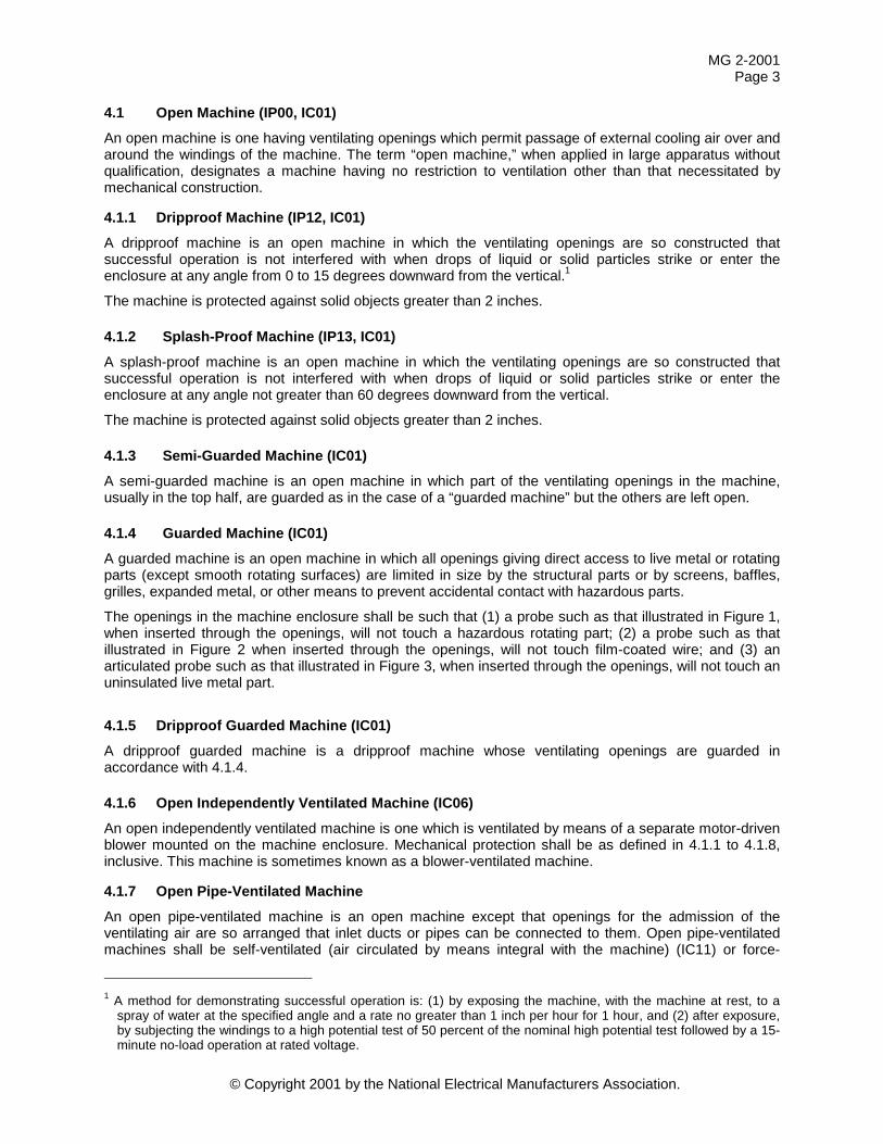
4.1.4 Guarded Machine (IC01) A guarded machine is an open machine in which all openings giving direct access to live metal or rotating parts (except smooth rotating surfaces) are limited in size by the structural parts or by screens, baffles, grilles, expanded metal, or other means to prevent accidental contact with hazardous parts.
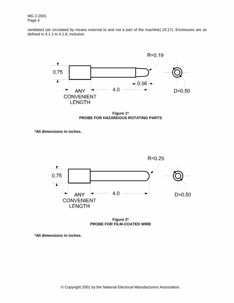
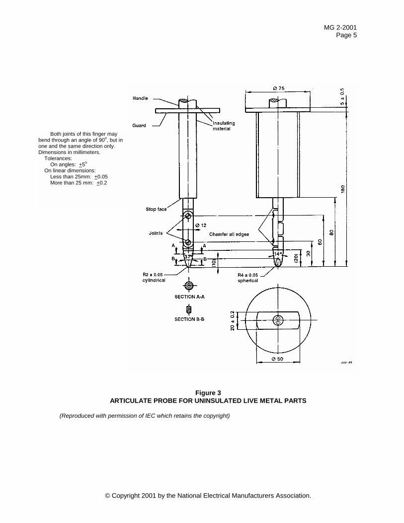
The openings in the machine enclosure shall be such that (1) a probe such as that illustrated in Figure 1, when inserted through the openings, will not touch a hazardous rotating part; (2) a probe such as that illustrated in Figure 2 when inserted through the openings, will not touch film-coated wire; and (3) an articulated probe such as that illustrated in Figure 3, when inserted through the openings, will not touch an uninsulated live metal part.
4.1.5 Dripproof Guarded Machine (IC01) A dripproof guarded machine is a dripproof machine whose ventilating openings are guarded in accordance with 4.1.4.
4.1.6 Open Independently Ventilated Machine (IC06) An open independently ventilated machine is one which is ventilated by means of a separate motor-driven blower mounted on the machine enclosure. Mechanical protection shall be as defined in 4.1.1 to 4.1.8, inclusive. This machine is sometimes known as a blower-ventilated machine.
4.1.7 Open Pipe-Ventilated Machine An open pipe-ventilated machine is an open machine except that openings for the admission of the ventilating air are so arranged that inlet ducts or pipes can be connected to them. Open pipe-ventilated machines shall be self-ventilated (air circulated by means integral with the machine) (IC11) or force-
1 A method for demonstrating successful operation is: (1) by exposing the machine, with the machine at rest, to a
spray of water at the specified angle and a rate no greater than 1 inch per hour for 1 hour, and (2) after exposure, by subjecting the windings to a high potential test of 50 percent of the nominal high potential test followed by a 15-minute no-load operation at rated voltage.
MG 2-2001 Page 4
© Copyright 2001 by the National Electrical Manufacturers Association.
ventilated (air circulated by means external to and not a part of the machine) (IC17). Enclosures are as defined in 4.1.1 to 4.1.8, inclusive.
Figure 1* PROBE FOR HAZARDOUS ROTATING PARTS
*All dimensions in inches.
Figure 2* PROBE FOR FILM-COATED WIRE
*All dimensions in inches.
MG 2-2001 Page 5
© Copyright 2001 by the National Electrical Manufacturers Association.
Figure 3 ARTICULATE PROBE FOR UNINSULATED LIVE METAL PARTS
(Reproduced with permission of IEC which retains the copyright)
Both joints of this finger may bend through an angle of 90o, but in one and the same direction only. Dimensions in millimeters.
Tolerances: On angles: +5o
On linear dimensions: Less than 25mm: +0.05 More than 25 mm: +0.2
MG 2-2001 Page 6
© Copyright 2001 by the National Electrical Manufacturers Association.
4.1.8 Weather-Protected Machine
4.1.8.1 Type I (IC01) A weather-protected Type I machine is a guarded machine with its ventilating passages so constructed as to minimize the entrance of rain, snow, and air-borne particles to the electric parts.
4.1.8.2 Type II (IC01) A weather-protected Type II machine shall have, in addition to the enclosure defined for a weather-protected Type I machine, its ventilating passages at both intake and discharge so arranged that high-velocity air and air-borne particles blown into the machine by storms or high winds can be discharged without entering the internal ventilating passages leading directly to the electric parts of the machine itself. The normal path of the ventilating air which enters the electric parts of the machine is so arranged by baffling or separate housings as to provide at least three abrupt changes in direction, none of which shall be less than 90 degrees. In addition, an area of low velocity not exceeding 600 feet per minute shall be provided in the intake air path to minimize the possibility of moisture or dirt being carried into the electric parts of the machine. Note: Removable or otherwise easy to clean filters may be provided instead of the low velocity chamber.
4.2 Totally Enclosed Machine A totally enclosed machine is so enclosed as to prevent the free exchange of air between the inside and outside of the case but not sufficiently enclosed to be termed air-tight and in which dust does not enter in sufficient quantity to interfere with satisfactory operation of the machine.
4.2.1 Totally Enclosed Nonventilated Machine (IC410) A totally enclosed nonventilated machine is a frame-surface cooled totally enclosed machine which is only equipped for cooling by free convection.
4.2.2 Totally Enclosed Fan-Cooled Machine A totally enclosed fan-cooled machine is a frame-surface cooled totally enclosed machine equipped for self exterior cooling by means of a fan or fans integral with the machine but external to the enclosing parts.
4.2.3 Totally Enclosed Fan-Cooled Guarded Machine (IC411) A totally-enclosed fan-cooled guarded machine is a totally-enclosed fan-cooled machine in which all openings giving direct access to the fan are limited in size by the design of the structural parts or by screens, grilles, expanded metal, etc., to prevent accidental contact with the fan. Such openings shall not permit the passage of a cylindrical rod 0.75 inch diameter, and a probe such as that shown in Figure 1 shall not contact the blades, spokes, or other irregular surfaces of the fan.
4.2.4 Totally Enclosed Pipe-Ventilated Machine (IP44) A totally enclosed pipe-ventilated machine is a machine with openings so arranged that when inlet and outlet ducts or pipes are connected to them there is no free exchange of the internal air and the air outside the case. Totally enclosed pipe-ventilated machines may be self-ventilated (air circulated by means integral with the machine [IC31]) or force-ventilated (air circulated by means external to and not part of the machine [IC37]).
4.2.5 Totally Enclosed Water-Cooled Machine (IP54) A totally enclosed water-cooled machine is a totally enclosed machine which is cooled by circulating water, the water or water conductors coming in direct contact with the machine parts.
MG 2-2001 Page 7
© Copyright 2001 by the National Electrical Manufacturers Association.
4.2.6 Water-Proof Machine (IP55) A water-proof machine is a totally enclosed machine so constructed that it will exclude water applied in the form of a stream of water from a hose, except that leakage may occur around the shaft provided it is prevented from entering the oil reservoir and provision is made for automatically draining the machine. The means for automatic draining may be a check valve or a tapped hole at the lowest part of the frame which will serve for application of a drain pipe.
4.2.7 Totally Enclosed Air-to-Water-Cooled Machine (IP54) A totally enclosed air-to-water-cooled machine is a totally enclosed machine which is cooled by circulating air which, in turn, is cooled by circulating water. It is provided with a water-cooled heat exchanger, integral (IC7_W) or machine mounted (IC8_W), for cooling the internal air and a fan or fans, integral with the rotor shaft (IC_1W) or separate (IC_5W) for circulating the internal air.
4.2.8 Totally Enclosed Air-to-Air-Cooled Machine (IP54) A totally enclosed air-to-air-cooled machine is a totally enclosed machine which is cooled by circulating the internal air through a heat exchanger which, in turn, is cooled by circulating external air. It is provided with an air-to-air heat exchanger, integral (IC5_), or machine mounted (IC6_), for cooling the internal air and a fan or fans, integral with the rotor shaft (IC_1_) or separate (IC_5_) for circulating the internal air and a fan or fans, integral with the rotor shaft (IC_1), or separate, but external to the enclosing part or parts (IC_6), for circulating the external air.
4.2.9 Totally Enclosed Air-Over Machine (IP54, IC417) A totally enclosed air-over machine is a totally enclosed frame-surface cooled machine intended for exterior cooling by a ventilating means external to the machine.
4.2.10 Explosion-Proof Machine1 An explosion-proof machine is a totally enclosed machine whose enclosure is designed and constructed to withstand an explosion of a specified gas or vapor which may occur within it and to prevent the ignition of the specified gas or vapor surrounding the machine by sparks, flashes, or explosions of the specified gas or vapor which may occur within the machine casing.
4.2.11 Dust-Ignition-Proof Machine2 A dust-ignition proof machine is a totally enclosed machine whose enclosure is designed and constructed in a manner which will exclude ignitable amounts of dust or amounts which might affect performance or rating, and which will not permit arcs, sparks, or heat otherwise generated or liberated inside of the enclosure to cause ignition of exterior accumulations or atmospheric suspensions of a specific dust on or in the vicinity of the enclosure.
Successful operation of this type of machine requires avoidance of overheating from such causes as excessive overloads, stalling, or accumulation of excessive quantities of dust on the machine.
5. CONSTRUCTION AND TESTS
5.1 General The provisions of the definitions in 4.1 and 4.2 for machine enclosures may be obtained by the construction of the machine housing or by the use of a supplemental enclosure, shield, or structure, provided such item is securely held in place; or by a combination of two or more such items when the machine is assembled to the driven or driving device.
1 See ANSI/NFPA 70, National Electrical Code, Article 500. For Hazardous Locations, Class I, Groups A, B, C, or D. 2 See ANSI/NFPA 70, National Electrical Code, Article 500. For Hazardous Locations, Class II, Groups E, F, or G.
MG 2-2001 Page 8
© Copyright 2001 by the National Electrical Manufacturers Association.
Tests for compliance with the definitions for guarded machines given in 4.1.4 and 4.2.3 are made from the exterior of the supplemental enclosure.
A machine enclosure, including that of parts mounted on a machine, is constructed so that it will have the strength and rigidity necessary to resist the normal service to which it may be subjected without reduction of spacings or displacement of parts.
Enclosures of nonmetallic material are resistant to adverse effects from exposure to moisture, oil, and temperature under normal conditions of use and are flame retardant.
In the case of capacitors mounted on or in the machine, the capacitor, or its supplementary enclosure, prevents the emission of flying fragments, flame, or molten material resulting from failure of the capacitor.
Totally-enclosed water-air-cooled machines have interior baffles, or other means, to prevent cooler-tube leakage and condensation from contacting the machine winding. The interior of the machine base shall be constructed so that coolant leakage will collect and drain from the machine before reaching the level of the windings.
For the selection and use of machine enclosures, see clause 4.
5.2 Corrosion Protection Iron and steel parts1, except bearings, laminations, and minor parts of iron and steel, such as washers, screws, and similar parts, are suitably protected against corrosion by enameling, galvanizing, plating, or by other equivalent means, if the failure of such unprotected parts would be likely to result in a hazardous condition.
5.3 High Potential Testing
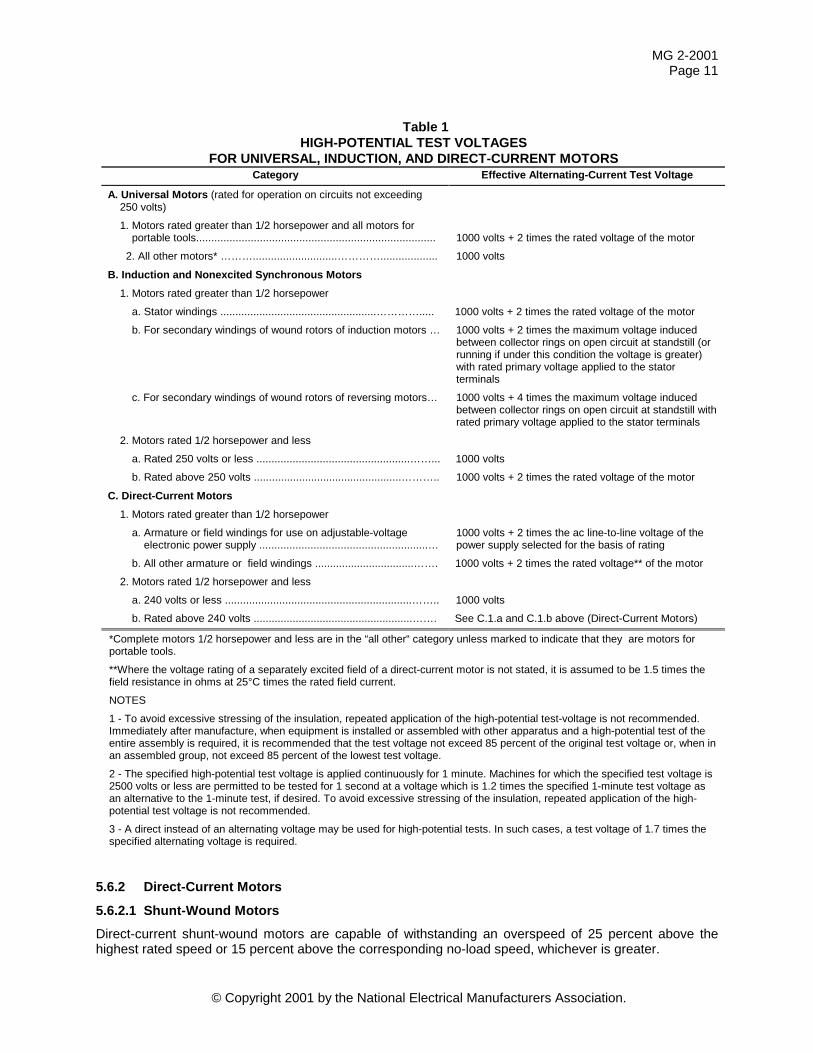
5.3.1 Motors Representative examples of high potential test voltages are provided in Table 1.
Motors are tested at these levels or greater in manufacturing. Since high potential testing is stressful on winding dielectric components it is recommended that field high potential test voltages be limited to 85 percent of the values shown in Table 1.
WARNING Because of the high voltages used, high potential tests should be conducted only by trained and qualified personnel and the following minimum safety precautions stated in 5.3.3 through 5.3.6 should be taken to avoid injury to personnel and damage to property.
5.3.2 Synchronous Generators Generators are tested at these levels or greater in manufacturing. Since high potential testing is stressful on winding dielectric components it is recommended that field high potential test voltages be limited to 85 percent of the following values.
5.3.2.1 Test Voltage — Armature Windings
The test voltage for all generators is an alternating voltage whose effective value is 1000 volts plus twice the rated voltage of the machine but in no case less than 1500 volts.
A direct instead of an alternating voltage is sometimes used for high-potential tests on primary windings of machines. In such cases, a test voltage equal to 1.7 times the alternating-current test voltage (effective value) as given in 4.3.2.1 and 4.3.2.2 is recommended. Following a direct-voltage high-potential test, the tested winding should be thoroughly grounded. The insulation rating of the winding and the test level of the voltage applied determine the period of time required to dissipate the charge and, in many cases, the ground should be maintained for several hours to dissipate the charge to avoid hazard to personnel.
1 In certain instances where the oxidation of iron or steel caused by the exposure of the metal to air and moisture is
not likely to be appreciable (thickness of metal and temperature also being factors) the surfaces of sheet steel and cast-iron parts within an enclosure need not be protected against corrosion
MG 2-2001 Page 9
© Copyright 2001 by the National Electrical Manufacturers Association.
5.3.2.2 Test Voltage — Field Windings, Generators with Slip Rings
The test voltage for all generators with slip rings is an alternating voltage whose effective value is as follows:
a) Rated excitation voltage < 500 volts direct current — ten times the rated excitation voltage but in no case less than 1500 volts
b) Rated excitation voltage > 500 volts direct current — 4000 volts plus twice the rated excitation voltage 5.3.2.3 Test Voltage — Assembled Brushless Generator Field Winding and Exciter Armature
Winding
The test voltage for all assembled brushless generator field windings and exciter armature windings is an alternating voltage whose effective value is as follows:
a) Rated excitation voltage < 500 volts direct current — ten times the rated excitation voltage but in no case less than 1500 volts
b) Rated excitation voltage > 500 volts direct current — 4000 volts plus twice the rated excitation voltage The brushless circuit components (diodes, thyristors, etc.) on an assembled brushless exciter and
synchronous machine field wiring are short-circuited (not grounded) during the test.
5.3.2.4 Test Voltage — Brushless Exciter Field Winding
The test voltage for all brushless exciter field windings is an alternating voltage whose effective value is as follows:
a) Rated excitation voltage < 500 volts direct current — ten times the rated excitation voltage but in no case less than 1500 volts
b) Rated excitation voltage > 500 volts direct current — 4000 volts plus twice the rated excitation voltage c) Exciters with alternating-current excited stators (fields) are tested at 1000 volts plus twice the rated
alternating-current voltage of the stator, but in no case less than 1500V
5.3.3 Grounding During high potential testing the frame and core and all external metal parts of the machine being tested should be grounded. During high potential testing all windings and components not under test should be connected together and then connected to the frame or core during high potential testing.
If the machine under test is to be ungrounded, proper precautions (which may include the selection of test equipment) should be taken to render the test and the test area safe for personnel.
5.3.4 Accessories and Components All accessories such as surge capacitors, lightning arresters, current transformers, and so forth, which have leads connected to the rotating machine terminals shall be disconnected during the test, with the leads connected together and to the frame or core. These accessories shall have been subjected to the high-potential test applicable to the class of apparatus at their point of manufacture. Capacitors of capacitor-type motors must be left connected to the winding in the normal manner for machine operation (running or starting).
Component devices and their circuits such as space heaters and temperature sensing devices in contact with the winding (thermostats, thermocouples, thermistors, resistance temperature detectors, and so forth) connected other than in the line circuit, shall be connected to the frame or core during machine winding high-potential tests. Each of these component device circuits, with leads connected together, shall then be tested by applying a voltage between the circuit and the frame or core, equal to twice the circuit rated voltage plus 1000 volts, or equal to the high-potential test voltage of the machine, whichever is lower. During each device circuit test all other machine windings and components shall be connected together and to the frame or core. Unless otherwise stated, the rated voltage of temperature sensing devices shall be taken as follows:
a) Thermostats 600 volts
MG 2-2001 Page 10
© Copyright 2001 by the National Electrical Manufacturers Association.
b) Thermocouples, thermistors, RTDs 50 volts.
When conducting a high-potential test on an assembled brushless exciter and synchronous machine field winding, the brushless circuit components (diodes, thyristors, and so forth) shall be short circuited (not grounded) during the test.
5.3.5 Discharging Windings After Test As a result of the alternating voltage high-potential test, the tested winding may retain a significant charge. The tested winding should be discharged to ground before it is touched by personnel.
Following a direct-voltage high-potential test, the tested windings should be discharged to ground. The insulation rating of the winding and the test level of the voltage applied determine the period of time required to dissipate the charge and, in many cases, the ground should be maintained for several hours to dissipate the charge to avoid hazard to personnel.
5.3.6 Guarding In the interest of safety, precautions shall be taken to prevent anyone from coming in contact with any part of the circuit or apparatus while high-potential tests are in progress.
5.4 Thermal Protection Motors provided with a thermal protector conforming to the requirements of MG 1-1.72, Thermal Protector (definition), are stamped Thermally Protected* on the nameplate.
A thermally protected motor is a motor which is protected against dangerous overheating due to overload and failure to start. *Motors rated 100 watts and less may be marked TP.
5.5 Impedance Protection Motors supplied as impedance protected are stamped Impedance Protected* on the nameplate.
An Impedance Protected motor is one in which the impedance of the motor windings is sufficient to prevent overheating due to failure to start. * Motors rated 100 watts and less may be marked ZP.
5.6 Overspeed It may be hazardous to operate a machine for a significant length of time at higher than rated speed. However, machines shall be so constructed that, in an emergency not to exceed 2 minutes, they will withstand without mechanical damage, overspeeds in accordance with the following specifications.
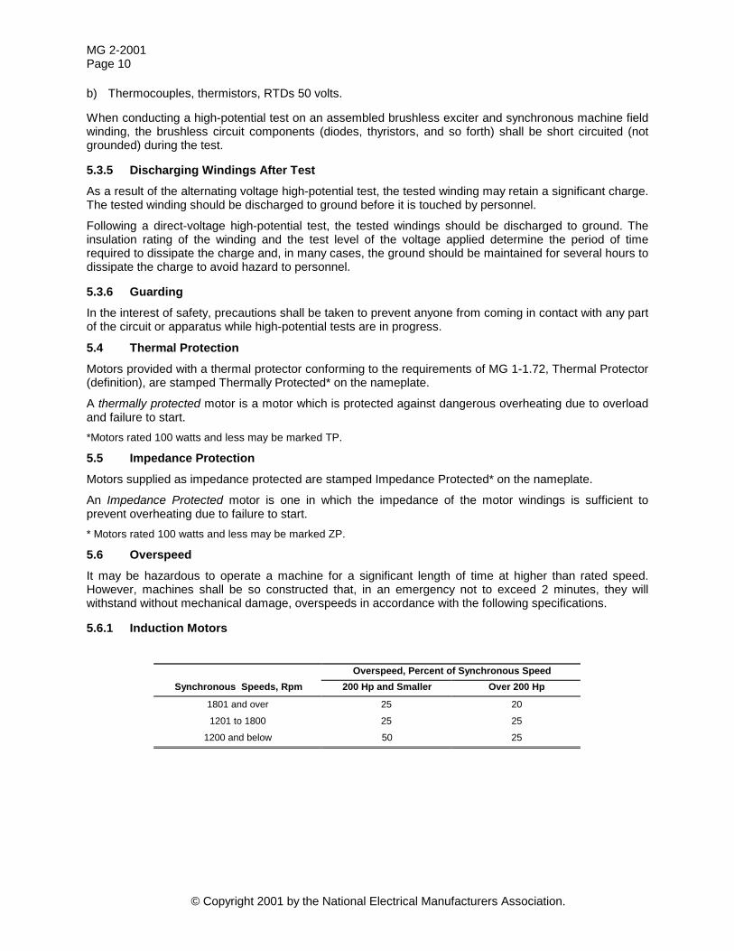
5.6.1 Induction Motors
Overspeed, Percent of Synchronous Speed Synchronous Speeds, Rpm 200 Hp and Smaller Over 200 Hp
1801 and over 25 20
1201 to 1800 25 25
1200 and below 50 25
MG 2-2001 Page 11
© Copyright 2001 by the National Electrical Manufacturers Association.
Table 1 HIGH-POTENTIAL TEST VOLTAGES
FOR UNIVERSAL, INDUCTION, AND DIRECT-CURRENT MOTORS Category Effective Alternating-Current Test Voltage
A. Universal Motors (rated for operation on circuits not exceeding 250 volts)
1. Motors rated greater than 1/2 horsepower and all motors for portable tools............................................................................... 1000 volts + 2 times the rated voltage of the motor
2. All other motors* ………............................…………................... 1000 volts
B. Induction and Nonexcited Synchronous Motors
1. Motors rated greater than 1/2 horsepower
a. Stator windings ....................................................…………..... 1000 volts + 2 times the rated voltage of the motor
b. For secondary windings of wound rotors of induction motors … 1000 volts + 2 times the maximum voltage induced between collector rings on open circuit at standstill (or running if under this condition the voltage is greater) with rated primary voltage applied to the stator terminals
c. For secondary windings of wound rotors of reversing motors… 1000 volts + 4 times the maximum voltage induced between collector rings on open circuit at standstill with rated primary voltage applied to the stator terminals
2. Motors rated 1/2 horsepower and less
a. Rated 250 volts or less ...................................................……... 1000 volts
b. Rated above 250 volts .................................................……….. 1000 volts + 2 times the rated voltage of the motor
C. Direct-Current Motors
1. Motors rated greater than 1/2 horsepower
a. Armature or field windings for use on adjustable-voltage electronic power supply ........................................................…
1000 volts + 2 times the ac line-to-line voltage of the power supply selected for the basis of rating
b. All other armature or field windings .................................……. 1000 volts + 2 times the rated voltage** of the motor
2. Motors rated 1/2 horsepower and less
a. 240 volts or less ..............................................................…….. 1000 volts
b. Rated above 240 volts .....................................................……. See C.1.a and C.1.b above (Direct-Current Motors)
*Complete motors 1/2 horsepower and less are in the “all other“ category unless marked to indicate that they are motors for portable tools.
**Where the voltage rating of a separately excited field of a direct-current motor is not stated, it is assumed to be 1.5 times the field resistance in ohms at 25°C times the rated field current.
NOTES
1 - To avoid excessive stressing of the insulation, repeated application of the high-potential test-voltage is not recommended. Immediately after manufacture, when equipment is installed or assembled with other apparatus and a high-potential test of the entire assembly is required, it is recommended that the test voltage not exceed 85 percent of the original test voltage or, when in an assembled group, not exceed 85 percent of the lowest test voltage.
2 - The specified high-potential test voltage is applied continuously for 1 minute. Machines for which the specified test voltage is 2500 volts or less are permitted to be tested for 1 second at a voltage which is 1.2 times the specified 1-minute test voltage as an alternative to the 1-minute test, if desired. To avoid excessive stressing of the insulation, repeated application of the high-potential test voltage is not recommended.
3 - A direct instead of an alternating voltage may be used for high-potential tests. In such cases, a test voltage of 1.7 times the specified alternating voltage is required.
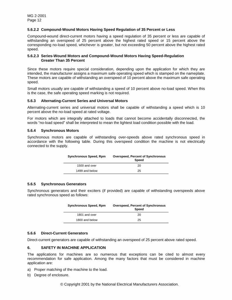
5.6.2 Direct-Current Motors
5.6.2.1 Shunt-Wound Motors Direct-current shunt-wound motors are capable of withstanding an overspeed of 25 percent above the highest rated speed or 15 percent above the corresponding no-load speed, whichever is greater.
MG 2-2001 Page 12
© Copyright 2001 by the National Electrical Manufacturers Association.
5.6.2.2 Compound-Wound Motors Having Speed Regulation of 35 Percent or Less Compound-wound direct-current motors having a speed regulation of 35 percent or less are capable of withstanding an overspeed of 25 percent above the highest rated speed or 15 percent above the corresponding no-load speed, whichever is greater, but not exceeding 50 percent above the highest rated speed.
5.6.2.3 Series-Wound Motors and Compound-Wound Motors Having Speed-Regulation Greater Than 35 Percent
Since these motors require special consideration, depending upon the application for which they are intended, the manufacturer assigns a maximum safe operating speed which is stamped on the nameplate. These motors are capable of withstanding an overspeed of 10 percent above the maximum safe operating speed.
Small motors usually are capable of withstanding a speed of 10 percent above no-load speed. When this is the case, the safe operating speed marking is not required.
5.6.3 Alternating-Current Series and Universal Motors Alternating-current series and universal motors shall be capable of withstanding a speed which is 10 percent above the no-load speed at rated voltage.
For motors which are integrally attached to loads that cannot become accidentally disconnected, the words “no-load speed” shall be interpreted to mean the lightest load condition possible with the load.
5.6.4 Synchronous Motors Synchronous motors are capable of withstanding over-speeds above rated synchronous speed in accordance with the following table. During this overspeed condition the machine is not electrically connected to the supply.
Synchronous Speed, Rpm Overspeed, Percent of Synchronous
Speed
1500 and over 20
1499 and below 25
5.6.5 Synchronous Generators Synchronous generators and their exciters (if provided) are capable of withstanding overspeeds above rated synchronous speed as follows:
Synchronous Speed, Rpm Overspeed, Percent of Synchronous
Speed
1801 and over 20
1800 and below 25
5.6.6 Direct-Current Generators Direct-current generators are capable of withstanding an overspeed of 25 percent above rated speed.
6. SAFETY IN MACHINE APPLICATION The applications for machines are so numerous that exceptions can be cited to almost every recommendation for safe application. Among the many factors that must be considered in machine application are:
a) Proper matching of the machine to the load. b) Degree of enclosure.
MG 2-2001 Page 13
© Copyright 2001 by the National Electrical Manufacturers Association.
c) Service conditions. d) Use of back-up equipment where the application requires exceptional reliability for the protection of life
and health, property, or perishable products.
Where the application or performance information beyond that contained in this publication is needed, NEMA Standards Publication MG 1 or the machine manufacturer, or both, should be consulted.
6.1 Matching of the Machine to the Load The application information required for the proper matching of a machine to the infinite variety of load requirements is beyond the scope of this publication. NEMA Standards Publication MG 1 provides basic application information along with minimum performance characteristics for machines to assist the user in making the proper selection of the machine for the particular application.
6.2 Degree of Machine Enclosure
6.2.1 General The required degree of enclosure of a machine, for personnel safety, is dependent upon the installation and application of the equipment. Therefore, the user or the manufacturer of the driven or driving equipment should consider the following questions when selecting the degree of enclosure for the machines:
a) Will the equipment be installed in: 1. Residences? 2. Places regularly open to the public? 3. Places frequented only by persons employed on the premises? 4. Places accessible only to qualified personnel?
b) Will the equipment be attended by an operator when it is in use? c) Are the size, location, appearance, and working arrangement of the equipment such that they will
discourage inappropriate use or approaches to the equipment? d) Is it possible to encounter hazard in the installed machine if it is approached or serviced in a manner
other than the manner for which it was designed? If so, are the hazards of such actions visibly obvious to the personnel operating, servicing, and generally having access to the machine?
The following recommendations for the selection of machine enclosures are given as a guide. If other than the recommended machine enclosures are to be applied, it is recommended that the installation be isolated and made inaccessible by fencing, by isolation in a room, by additional enclosures, or by other means, so that access to the isolated areas is limited only to qualified personnel. Qualified personnel are those who are familiar with the construction and operation of the equipment and with the hazards involved. Refer to Table 2 for a description of IP Codes designating degrees of protection.
6.2.2 Application in Residences and in Places Regularly Open to the Public For those applications in residences and in places which are regularly open to the public and which cannot be isolated from the public, only the following machines should be used:
a) Guarded machines;1 b) Totally-enclosed nonventilated machines; c) Totally-enclosed fan-cooled guarded machines; d) Totally-enclosed water-air-cooled machines; e) Totally-enclosed pipe-ventilated machines; f) Weather-protected machines; and g) Open machines when the enclosure of the equipment provides the equivalent of a guarded machine.
1 Certain machine applications may require openings smaller than those mentioned for a guarded machine.
MG 2-2001 Page 14
© Copyright 2001 by the National Electrical Manufacturers Association.
6.2.3 Applications in Places Restricted to Persons Employed on the Premises Many years of experience in industrial plants, light commercial installations, and other areas where access to the equipment is normally restricted to persons employed on the premises have established that the following machines have a successful and satisfactory safety record:
a) Dripproof machines; b) Semi-guarded machines; c) Totally-enclosed fan-cooled machines; and d) Machines recommended above for use in places regularly open to the public.
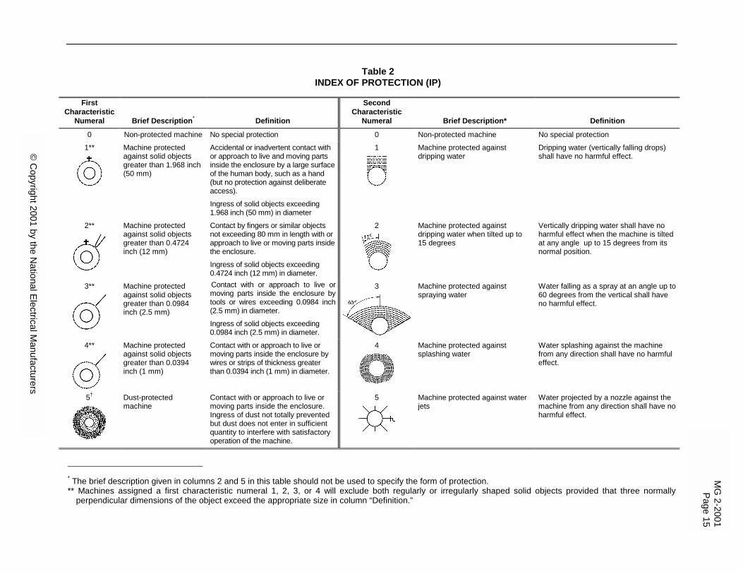
Table 2 INDEX OF PROTECTION (IP)
First
Characteristic Numeral Brief Description*
Definition
Second Characteristic
Numeral
Brief Description*
Definition
0 Non-protected machine No special protection 0 Non-protected machine No special protection
1**
Machine protected against solid objects greater than 1.968 inch (50 mm)
Accidental or inadvertent contact with or approach to live and moving parts inside the enclosure by a large surface of the human body, such as a hand (but no protection against deliberate access).
Ingress of solid objects exceeding 1.968 inch (50 mm) in diameter
1
Machine protected against dripping water
Dripping water (vertically falling drops) shall have no harmful effect.
2**
Machine protected against solid objects greater than 0.4724 inch (12 mm)
Contact by fingers or similar objects not exceeding 80 mm in length with or approach to live or moving parts inside the enclosure.
Ingress of solid objects exceeding 0.4724 inch (12 mm) in diameter.
2
Machine protected against dripping water when tilted up to 15 degrees
Vertically dripping water shall have no harmful effect when the machine is tilted at any angle up to 15 degrees from its normal position.
3**
Machine protected against solid objects greater than 0.0984 inch (2.5 mm)
Contact with or approach to live or moving parts inside the enclosure by tools or wires exceeding 0.0984 inch (2.5 mm) in diameter.
Ingress of solid objects exceeding 0.0984 inch (2.5 mm) in diameter.
3 Machine protected against spraying water
Water falling as a spray at an angle up to 60 degrees from the vertical shall have no harmful effect.
4**
Machine protected against solid objects greater than 0.0394 inch (1 mm)
Contact with or approach to live or moving parts inside the enclosure by wires or strips of thickness greater than 0.0394 inch (1 mm) in diameter.
4
Machine protected against splashing water
Water splashing against the machine from any direction shall have no harmful effect.
5†
Dust-protected machine
Contact with or approach to live or moving parts inside the enclosure. Ingress of dust not totally prevented but dust does not enter in sufficient quantity to interfere with satisfactory operation of the machine.
5
Machine protected against water jets
Water projected by a nozzle against the machine from any direction shall have no harmful effect.
* The brief description given in columns 2 and 5 in this table should not be used to specify the form of protection. ** Machines assigned a first characteristic numeral 1, 2, 3, or 4 will exclude both regularly or irregularly shaped solid objects provided that three normally
perpendicular dimensions of the object exceed the appropriate size in column “Definition.”
MG
2-2001Page 15
© C
opyright 2001 by the National Electrical M
anufacturers
© Copyright 2001 by the National Electrical Manufacturers Association.
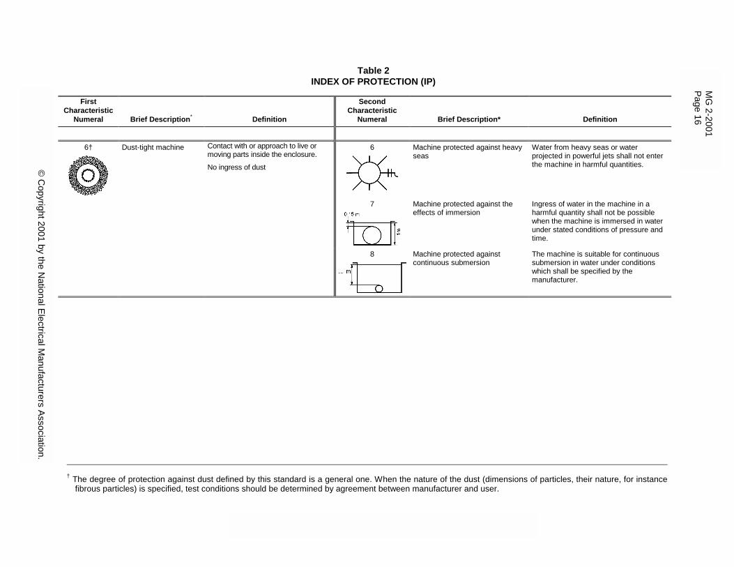
Table 2 INDEX OF PROTECTION (IP)
First
Characteristic Numeral Brief Description*
Definition
Second Characteristic
Numeral
Brief Description*
Definition
6†
Dust-tight machine Contact with or approach to live or moving parts inside the enclosure.
No ingress of dust
6
Machine protected against heavy seas
Water from heavy seas or water projected in powerful jets shall not enter the machine in harmful quantities.
7
Machine protected against the effects of immersion
Ingress of water in the machine in a harmful quantity shall not be possible when the machine is immersed in water under stated conditions of pressure and time.
8 Machine protected against continuous submersion
The machine is suitable for continuous submersion in water under conditions which shall be specified by the manufacturer.
† The degree of protection against dust defined by this standard is a general one. When the nature of the dust (dimensions of particles, their nature, for instance
fibrous particles) is specified, test conditions should be determined by agreement between manufacturer and user.
MG
2-2001 Page 16
© C
opyright 2001 by the National Electrical M
anufacturers Association.
MG 2-2001 Page 17
© Copyright 2001 by the National Electrical Manufacturers Association.
6.2.4 Application in Places Accessible Only to Qualified Personnel Any of the machine enclosures mentioned in 6.2.3 may be used in these places. In addition, many years of experience in power plants and in other applications where machines are so located or installed that they are accessible only to qualified personnel have established that open machines have a successful and satisfactory safety record.
6.2.5 AC Motors For Class I, Division 2, Hazardous Locations Open or nonexplosion-proof enclosed motors are allowed by the National Electrical Code as long as they do not have brushes, switching mechanisms, or other similar arc-producing devices. Accordingly, the user has two possibilities when selecting a motor for Class I, Division 2 applications.
The recommended approach for the user is to select an explosion-proof motor, which in accordance with Underwriters Laboratories Inc. requirements, shall not exceed the specified external surface temperature under any operating condition.
As an alternative, the user may select an open or nonexplosion-proof enclosed motor for submission to the local authority for approval. Since the enclosure is not explosion-proof, the user should consider the temperature of external and internal surfaces of the motor to which the surrounding atmosphere has access.
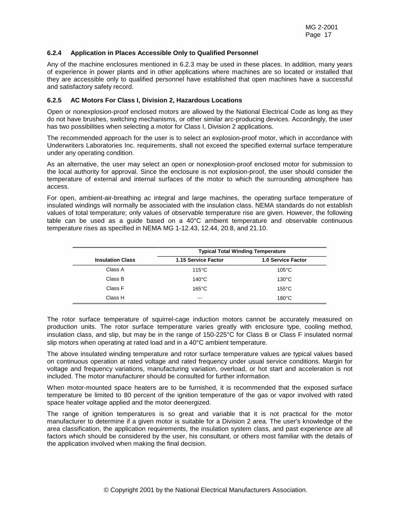
For open, ambient-air-breathing ac integral and large machines, the operating surface temperature of insulated windings will normally be associated with the insulation class. NEMA standards do not establish values of total temperature; only values of observable temperature rise are given. However, the following table can be used as a guide based on a 40°C ambient temperature and observable continuous temperature rises as specified in NEMA MG 1-12.43, 12.44, 20.8, and 21.10.
Typical Total Winding Temperature Insulation Class 1.15 Service Factor 1.0 Service Factor
Class A 115°C 105°C
Class B 140°C 130°C
Class F 165°C 155°C
Class H --- 180°C
The rotor surface temperature of squirrel-cage induction motors cannot be accurately measured on production units. The rotor surface temperature varies greatly with enclosure type, cooling method, insulation class, and slip, but may be in the range of 150-225°C for Class B or Class F insulated normal slip motors when operating at rated load and in a 40°C ambient temperature.
The above insulated winding temperature and rotor surface temperature values are typical values based on continuous operation at rated voltage and rated frequency under usual service conditions. Margin for voltage and frequency variations, manufacturing variation, overload, or hot start and acceleration is not included. The motor manufacturer should be consulted for further information.
When motor-mounted space heaters are to be furnished, it is recommended that the exposed surface temperature be limited to 80 percent of the ignition temperature of the gas or vapor involved with rated space heater voltage applied and the motor deenergized.
The range of ignition temperatures is so great and variable that it is not practical for the motor manufacturer to determine if a given motor is suitable for a Division 2 area. The user's knowledge of the area classification, the application requirements, the insulation system class, and past experience are all factors which should be considered by the user, his consultant, or others most familiar with the details of the application involved when making the final decision.
MG 2-2001 Page 18
© Copyright 2001 by the National Electrical Manufacturers Association.
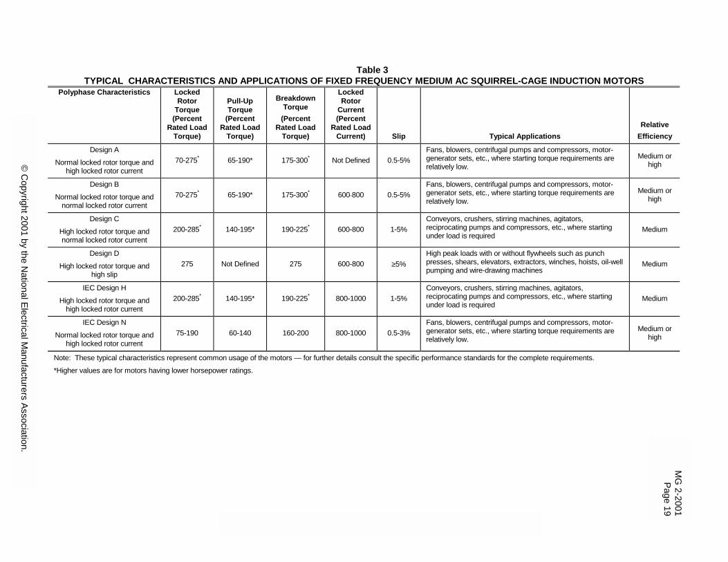
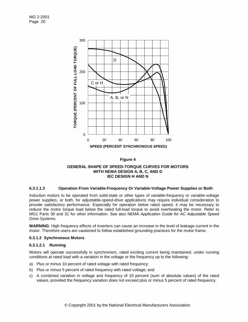
6.3 Proper Selection of Machines Machines should be properly selected with respect to their usual or unusual service conditions, both of which involve the environmental and operating conditions to which the machine is subjected. Machines conforming to the Scope of this publication are designed for operation in accordance with their ratings under usual service conditions. Some typical applications for motors of standard Design types are given in Table 3. Typical speed torque characteristics are shown in Figure 4. Some machines may also be capable of operating in accordance with their ratings under one or more unusual service conditions. Definite-purpose or special-purpose machines may be required for some unusual conditions.
Good energy management is the successful application of the motor controller, motor, and the driven components that results in the least consumption of energy. Since all motors do not have the same efficiency, careful consideration must be given to their selection and application. For further information and guidance, see MG 10 Energy Management Guide for Selection and Use of Fixed Frequency Medium AC Squirrel-Cage Polyphase Induction Motors.
Service conditions, other than those specified as usual, may involve some degree of hazard. The additional hazard depends upon the degree of departure from usual operating conditions and the severity of the environment to which the machine is exposed. The additional hazard results from such things as overheating, mechanical failure, abnormal deterioration of the insulation system, corrosion, fire, or explosion.
Although past experience of the user may often be the best guide, the manufacturer of the driven or driving equipment or the machine manufacturer, or both, should be consulted for further information regarding any unusual service conditions which increase the mechanical or thermal duty of the machine and, as a result, increase the chances for failure and consequent hazard. This further information should be considered by the user, his consultants, or others most familiar with the details of the application involved when making the final decision.
6.3.1 Variation From Rated Voltage and Rated Frequency
6.3.1.1 Induction Motors
6.3.1.1.1 Running Motors will operate successfully under running conditions at rated load with a variation in the voltage or the frequency up to the following:
a) Plus or minus 10 percent of rated voltage with rated frequency. b) Plus or minus 5 percent of rated frequency with rated voltage. c) A combined variation in voltage and frequency of 10 percent (sum of absolute values) of the rated
values, provided the frequency variation does not exceed plus or minus 5 percent of rated frequency.
Performance within these voltage and frequency variations will not necessarily be in accordance with the standards established for operation at rated voltage and frequency.
6.3.1.1.2 Starting The limiting values of voltage and frequency under which a motor will successfully start and accelerate to running speed depend on the margin between the speed-torque curve of the motor at rated voltage and frequency and the speed-torque curve of the load under starting conditions. Since the torque developed by the motor at any speed is approximately proportional to the square of the voltage and inversely proportional to the square of the frequency, it is generally desirable to determine what voltage and frequency variations will actually occur at each installation, taking into account any voltage drop resulting from the starting current drawn by the motor. This information and the torque requirements of the driven machine define the motor speed torque-curve, at rated voltage and frequency, which is adequate for the application.
© Copyright 2001 by the National Electrical Manufacturers Association.
Table 3 TYPICAL CHARACTERISTICS AND APPLICATIONS OF FIXED FREQUENCY MEDIUM AC SQUIRREL-CAGE INDUCTION MOTORS
Polyphase Characteristics Locked Rotor
Torque (Percent
Rated Load Torque)
Pull-Up Torque
(Percent Rated Load
Torque)
Breakdown Torque
(Percent Rated Load
Torque)
Locked Rotor
Current (Percent
Rated Load Current) Slip Typical Applications
Relative Efficiency
Design A
Normal locked rotor torque and high locked rotor current
70-275* 65-190* 175-300* Not Defined 0.5-5% Fans, blowers, centrifugal pumps and compressors, motor-generator sets, etc., where starting torque requirements are relatively low.
Medium or high
Design B
Normal locked rotor torque and normal locked rotor current
70-275* 65-190* 175-300* 600 800 0.5-5% Fans, blowers, centrifugal pumps and compressors, motor-generator sets, etc., where starting torque requirements are relatively low.
Medium or high
Design C
High locked rotor torque and normal locked rotor current
200-285* 140-195* 190-225* 600-800 1-5% Conveyors, crushers, stirring machines, agitators, reciprocating pumps and compressors, etc., where starting under load is required
Medium
Design D
High locked rotor torque and high slip
275 Not Defined 275 600-800 ≥5% High peak loads with or without flywheels such as punch presses, shears, elevators, extractors, winches, hoists, oil-well pumping and wire-drawing machines
Medium
IEC Design H
High locked rotor torque and high locked rotor current
200-285* 140-195* 190-225* 800-1000 1-5% Conveyors, crushers, stirring machines, agitators, reciprocating pumps and compressors, etc., where starting under load is required
Medium
IEC Design N
Normal locked rotor torque and high locked rotor current
75-190 60-140 160-200 800-1000 0.5-3% Fans, blowers, centrifugal pumps and compressors, motor-generator sets, etc., where starting torque requirements are relatively low.
Medium or high
Note: These typical characteristics represent common usage of the motors — for further details consult the specific performance standards for the complete requirements.
*Higher values are for motors having lower horsepower ratings.
MG
2-2001Page 19
© C
opyright 2001 by the National Electrical M
anufacturers Association.
MG 2-2001 Page 20
© Copyright 2001 by the National Electrical Manufacturers Association.
Figure 4
GENERAL SHAPE OF SPEED-TORQUE CURVES FOR MOTORS WITH NEMA DESIGN A, B, C, AND D
IEC DESIGN H AND N
6.3.1.1.3 Operation From Variable-Frequency Or Variable-Voltage Power Supplies or Both Induction motors to be operated from solid-state or other types of variable-frequency or variable-voltage power supplies, or both, for adjustable-speed-drive applications may require individual consideration to provide satisfactory performance. Especially for operation below rated speed, it may be necessary to reduce the motor torque load below the rated full-load torque to avoid overheating the motor. Refer to MG1 Parts 30 and 31 for other information. See also NEMA Application Guide for AC Adjustable Speed Drive Systems.
WARNING: High frequency effects of inverters can cause an increase in the level of leakage current in the motor. Therefore users are cautioned to follow established grounding practices for the motor frame.
6.3.1.2 Synchronous Motors
6.3.1.2.1 Running Motors will operate successfully in synchronism, rated exciting current being maintained, under running conditions at rated load with a variation in the voltage or the frequency up to the following:
a) Plus or minus 10 percent of rated voltage with rated frequency; b) Plus or minus 5 percent of rated frequency with rated voltage; and c) A combined variation in voltage and frequency of 10 percent (sum of absolute values) of the rated
values, provided the frequency variation does not exceed plus or minus 5 percent of rated frequency.
0
100
200
300
0 20 40 60 80 100
SPEED (PERCENT SYNCHRONOUS SPEED)
TOR
QU
E (P
ERC
ENT
OF
FULL
-LO
AD T
OR
QU
E)
A, B, or N
C or H
D
MG 2-2001 Page 21
© Copyright 2001 by the National Electrical Manufacturers Association.
Performance within these voltage and frequency variations will not necessarily be in accordance with the standards established for operation at rated voltage and frequency.
6.3.1.2.2 Starting The limiting values of voltage and frequency under which a motor will successfully start and synchronize depend upon the margin between the locked-rotor and pull-in torques of the motor at rated voltage and frequency and the corresponding requirements of the load under starting conditions. Since the locked-rotor and pull-in torques of a motor are approximately proportional to the square of the voltage and inversely proportional to the square of the frequency, it is generally desirable to determine what voltage and frequency variation will actually occur at each installation, taking into account any voltage drop resulting from the starting current drawn by the motor. This information and the torque requirements of the driven machine determine the values of locked-rotor and pull-in torque at rated voltage and frequency that are adequate for the application.
6.3.1.2.3 Operation From Variable-Frequency Power Supplies Synchronous motors to be operated from solid-state or other types of variable-frequency power supplies for adjustable-speed-drive applications, may require individual consideration to provide satisfactory performance. Especially for operation below rated speed, it may be necessary to reduce the motor torque load below the rated full-load torque to avoid overheating the motor. The motor manufacturer should be consulted before selecting a motor for such application.
6.3.1.3 Synchronous Generators Synchronous generators will operate successfully at rated kVA, frequency, and power factor with a variation in the output voltage up to plus or minus 5 percent of rated voltage.
Performance within these voltage variations will not necessarily be in accordance with the standards established for operation at rated voltage.
6.3.1.4 Direct-current Motors Direct-current motors will operate successfully using the power supply selected for the basis of rating up to and including 110 percent of rated direct-current armature voltage provided the highest rated speed is not exceeded. Direct-current motors rated for operation from a rectifier power supply will operate successfully with a variation of plus or minus 10 percent of rated alternating-current line voltage.
Performance within this voltage variation will not necessarily be in accordance with the standards established for operation at rated voltage. For operation below base speed, see 6.3.4.
6.3.2 Usual Service Conditions
6.3.2.1 Environmental Conditions Machines are designed for the following operating site conditions, unless other conditions are specified by the purchaser.
a) Exposure to an ambient temperature in the range of -15°C to 40°C or, when water cooling is used, an ambient temperature range of 5°C (to prevent freezing of water) to 40°C, except for machines rated less than 3/4 hp and all machines other than water cooled having commutator or sleeve bearings for which the minimum ambient temperature is 0°C
b) Exposure to an altitude which does not exceed 3300 feet (1000 meters) c) Installation on a rigid mounting surface d) Installation in areas or supplementary enclosures which do not seriously interfere with the ventilation
of the machine 6.3.2.2 Operating Conditions a) V-belt drive in accordance with MG 1-14.42 for alternating-current motors and with MG 1-14.67 for
industrial direct-current motors b) Flat-belt, chain, and gear drives in accordance with MG 1-14.7
MG 2-2001 Page 22
© Copyright 2001 by the National Electrical Manufacturers Association.
6.3.3 Unusual Service Conditions The manufacturer should be consulted if any unusual service conditions exist which may affect the construction or operation of the motor. Among such conditions are:
a) Exposure to: 1. Combustible, explosive, abrasive, or conducting dusts 2. Lint or very dirty operating conditions where the accumulation of dirt may interfere with normal
ventilation 3. Chemical fumes, flammable or explosive gases 4. Nuclear radiation 5. Steam, salt-laden air, or oil vapor 6. Damp or very dry locations, radiant heat, vermin infestation, or atmospheres conducive to the
growth of fungus 7. Abnormal shock, vibration, or mechanical loading from external sources 8. Abnormal axial or side thrust imposed on the motor shaft
b) Operation where: 1. There is excessive departure from rated voltage or frequency, or both (see 6.3.1.1.1 for
alternating-current motors and 6.3.1.4 for direct-current motors) 2. The deviation factor of the alternating-current supply voltage exceeds 10 percent 3. The alternating-current supply voltage is unbalanced by more than 1 percent (see MG 1-12.46
and MG 1-14.36) 4. The rectifier output supplying a direct-current motor is unbalanced so that the difference between
the highest and lowest peak amplitudes of the current pulses over one cycle exceed 10 percent of the highest pulse amplitude at rated armature current
5. Low noise levels are required 6. The power system is not grounded (see MG 1-14.31)
c) Operation at speeds above the highest rated speed d) Operation in a poorly ventilated room, in a pit, or in an inclined position e) Operation where subjected to:
1. Torsional impact loads 2. Repetitive abnormal overloads 3. Reversing or electric braking 4. Frequent starting (see MG 1-12.55) 5. Out-of-phase bus transfer (see MG 1-20.34) 6. Frequent short circuits
f) Operation of machine at standstill with any winding continuously energized or of short-time-rated machine with any winding continuously energized
g) Operation of direct-current machine where the average armature current is less than 50 percent of the rated full-load amperes over a 24-hour period, or continuous operation at armature current less than 50 percent of rated current for more than 4 hours
6.3.4 Speed Limitation
6.3.4.1 Operation Below Rated or Base Speed When a machine is operated below rated speed (base speed in the case of direct-current motors), it may be necessary to reduce its loading in order to avoid overheating. Overheating may result from reduced ventilation, changes in power supply characteristics, or changes in the characteristics of the machine. The manufacturer of the driven or driving equipment or the manufacturer of the machine, or both, should be consulted for further information regarding applications where operation below rated or base speed is
MG 2-2001 Page 23
© Copyright 2001 by the National Electrical Manufacturers Association.
contemplated. This further information should be considered by the user, his consultants, or others most familiar with the details of the application involved when making the final decision.
6.3.4.2 Operation Above Highest Rated Speed Series motors and direct-current compound-wound and shunt-wound motors are subject to overspeeding under certain conditions of misoperation.
A series motor with no load (or light load) connected to it will increase in speed very rapidly, and the armature may be thrown apart by centrifugal force. Series motors should therefore be positively connected to the driven load in a manner which will not allow the motor to become disconnected accidentally from the driven load.
Dangerous overspeeding of a direct-current compound-wound or shunt-wound motor may occur if the shunt field circuit becomes deenergized. Unless the speed is inherently limited by the application of the motor, these motors should be protected against dangerous overspeed by overspeed devices, field loss relays, or other means.
6.3.5 Operation of Direct-current Motors on Rectified Alternating Current
6.3.5.1 General When a direct-current motor is operated from a rectified alternating-current supply, its performance may differ materially from that of the same motor when operated from a low-ripple direct-current source of supply, such as a generator or a battery. The pulsating voltage and current wave forms may increase temperature rise and noise and adversely affect commutation and efficiency. Because of these effects, it may be necessary that direct-current motors be designed or specifically selected to operate on the particular type of rectifier to be used.
6.3.5.2 Motors Built in Frames Having a Continuous Dripproof Rating or Equivalent Capacity, Up to and Including 1.25 Horsepower per RPM, Open Type
Standards for these motors, as contained in Parts 4, 10, 12, and 14 of NEMA Standards Publication MG 1, set forth a basis of rating direct-current motors intended for use with rectifier power supplies. These ratings are based upon tests of the motors using a test power supply.
Small motors are identified on the nameplate by means of a rated form factor, whereas medium motors are identified on the nameplate by a single letter or a combination of digits and letters designating a particular type of rectifier power supply.
All direct-current motors intended for use on rectifier power supplies may be used on low-ripple power supplies such as a direct-current generator or battery. In addition, motors identified by a rated form factor or a single identifying letter may be used on a power supply having a lower form factor or on a power supply designated or identified by a lower letter of the alphabet. For example, a motor rated on the basis of an E power supply may be used on a C or D power supply.
For operation of direct-current motors on power supplies other than those used to establish the basis of rating (except as noted above), the combination of the power supply and the motor should be considered in combination with the motor manufacturer.
6.3.5.3 Motors Built in Frames Larger than Those Having a Continuous Dripproof Rating, or Equivalent Capacity, of 1.25 Horsepower per RPM, Open Type
Standards for these motors, as contained in Part 23 of NEMA Standards Publication MG 1, are based on operation from a low-ripple power supply. The power supply and series inductance (including motor armature) selected should be such that the magnitude of the ripple current (peak-to-peak), expressed in percent of rated load current, does not exceed 6 percent at rated load, rated armature voltage, and rated base speed. For operation on other power supplies, the combination of the power supply and the motor should be considered in consultation with the motor manufacturer.
MG 2-2001 Page 24
© Copyright 2001 by the National Electrical Manufacturers Association.
6.3.5.4 Bearing Currents When a direct-current motor is operated from some unfiltered rectifier power supplies, bearing currents may result. Ripple currents, transmitted by capacitive coupling between the rotor winding and the core, may flow through the ground path to the transformer secondary. While these currents are small in magnitude, they may cause damage to either antifriction or sleeve bearings under certain circumstances. It is recommended that the manufacturer be consulted to determine whether bearing currents may be a problem and, if so, what measures can be taken to minimize them.
6.3.6 Shaft Loading Hazards can be created by overstressing the motor or generator shaft by such means as misalignment of couplings, overtightening belts, and so forth, or by using V-belt sheaves, gear pinions, or chain sprockets smaller in diameter than provided for in the design of the machine. In coupling to the motor or generator shaft, the practices outlined in Part 14 of NEMA Standards Publication MG 1 should be followed, or the machine manufacturer should be consulted.
6.3.7 Transient Torques Machines are inherently capable of developing transient torques considerably in excess of their rated torque when exposed to any of the following conditions:
a) Bus transfer; b) Out-of-phase synchronizing; c) Plugging; d) Speed transfer or regenerative braking, or both, of multispeed motors; or e) External short circuits.
The magnitude of these transient torques ranges from 2 to 20 times rated torque as a function of the machine operating conditions, switching times, system inertia, and so forth.
To avoid the possibility of damaging equipment (that is, shafts, couplings, gears, and so forth), the peak magnitude of the transient torques likely to be encountered should be considered in the design of the system. The machine manufacturer should be consulted regarding the peak magnitude of the transient air-gap torque, and this information should be considered by the manufacturer of the driven or driving equipment, the user, his consultants, or others most familiar with the details of the application involved when making the final decision.
MG 1-20.34, and 21.35 provide basic application information relative to bus transfer or reclosing. It is recommended that slow transfer or reclosing be used when possible. A slow transfer or reclosing is defined as one in which the length of time between disconnection of the machine from the power supply and reclosing onto the same or another power supply is equal to or greater than one and a half machine open-circuit alternating-current time constants. When it is necessary to perform the bus transfer or reclosing in a shorter time, referred to as a fast transfer or reclosing, it is recommended that the electromechanical interactions of the machine, the driven or driving equipment, and the power system be studied to evaluate the effects of the fast transfer or reclosing.
6.3.8 Torsional Vibration Overstressed shafts or couplings and other hazards can result from equipment which subjects machines to excessive torsional vibration. Unlike lateral vibrations that can be readily sensed by touch and measured with relatively common instruments, torsional vibrations with considerable amplitudes can exist and be undetectable except by special, relatively uncommon instruments. Since torsional vibrations are so difficult to detect and measure, it is particularly important that torsional stresses be considered when machines are to drive or be driven by equipment producing periodic torque pulses, such as reciprocating engines, chippers, hammer mills, and so forth.
While the factors which affect torsional vibration are primarily contained in the design of the equipment external to the motor, the design of the machine rotor to which the external equipment is mechanically
MG 2-2001 Page 25
© Copyright 2001 by the National Electrical Manufacturers Association.
connected should also be considered. When the manufacturer of the external equipment makes a torsional analysis of the complete assembly, the machine manufacturer should be consulted for the rotor design data which affects torsional vibration.
6.3.9 Torque Pulsations During Starting of Synchronous Motors When operated at other than synchronous speed, all salient-pole synchronous motors develop a pulsating torque superimposed on the average torque. During starting and acceleration (with no field excitation applied), the frequency of the torque pulsations is at any instant equal to the per-unit slip times twice the line frequency. Thus, for a 60-hertz motor, the frequency of the torque pulsation varies from 120 hertz at zero speed to zero hertz at synchronous speed.
Any system consisting of inertias connected by shafting has one or more natural torsional frequencies. During acceleration by a salient-pole synchronous motor, any torsional natural frequency at or below twice line frequency will be transiently excited.
When it is desired to investigate the magnitudes of the torques which are transiently imposed upon the shafting during starting, the instantaneous torque pulsations should be considered in addition to the average torque.
7. SAFETY IN MACHINE INSTALLATIONS
7.1 Installation and Protection All machines covered by this publication should be installed and protected in accordance with the applicable provisions of national codes and sound local practices.
7.2 Grounding The frames and other metal exteriors of machines (except for insulated pedestal bearings) usually should be grounded to limit their potential to ground in the event of accidental connection or contact between live electrical parts and the metal exteriors. See the National Electrical Code, Article 430, Part L, for information on grounding of motors; Article 445 for grounding of generators; and Article 250 for general information on grounding. In making the ground connection, the installer should make certain that there is a solid and permanent metallic connection between the ground point, the machine terminal housing, and the machine frame. A common method of providing a ground is through a grounded metallic conduit system.
Motors with resilient cushion rings are usually supplied with a bonding conductor across the resilient member. Some motors are supplied with the bonding conductor on the concealed side of the cushion ring to protect the bond from damage. Motors with bonded cushion rings should usually be grounded at the time of installation. When motors with bonded cushion rings are used in multimotor installations employing group fusing or group protection, the bonding of the cushion ring should be checked to determine that it is adequate for the rating of the branch circuit overcurrent protective device being used.
There are applications where grounding the exterior parts of a machine may result in greater hazard by increasing the possibility of a person in the area simultaneously contacting ground and some other nearby live electrical part or other ungrounded electrical equipment. In portable equipment, it is difficult to be sure that a positive ground connection is maintained as the equipment is moved, and providing a grounding conductor may lead to a false sense of security. When careful consideration of the hazards involved in a particular application indicates the machine frames should not be grounded or when unusual operating conditions dictate that a grounded frame cannot be used, the installer should make sure the machine is permanently and effectively insulated from ground. In those installations where the machine frame is insulated from ground, it is recommended that appropriate warning labels or signs be placed on or in the area of the equipment by the installer.
7.3 Wiring Connections The connection of the machine to the power supply should be made by qualified personnel in accordance with the diagram or other instructions furnished by the machine manufacturer. Where the machine has provision for use on different values of voltage by alteration of the connections, care should be taken to ensure that the connections made are correct for the voltage supplied to the machine.
MG 2-2001 Page 26
© Copyright 2001 by the National Electrical Manufacturers Association.
If a machine having a cord and attachment plug cap is required to be reconnected for operation on a different voltage, it is recommended that the changes be made by a qualified electrician. Care should be taken to ensure that the attachment plug cap is replaced with one of a type suitable for the voltage for which the machine is reconnected and that all of the instructions of the machine manufacturer are followed, since improper connections could result in the machine becoming a shock hazard.
7.4 Flammable Materials Sparking of brushes on commutator or collector rings may be expected during normal operation. In addition, open-type machines may eject flame or molten metal, or both, in the event of an insulation failure, commutator flashover, or arc-over of collector rings. Therefore, consideration should be given to the avoidance or protection of flammable or combustible materials in the area of open-type machines.
7.5 Rotating Parts Except for openings in machine enclosures (see 4.1), the guarding of rotating parts such as couplings, pulleys, and unused shaft extensions, should be in accordance with ANSI B15.1. This is particularly important where the parts have surface irregularities such as keys, keyways, or set screws. Some satisfactory methods of guarding are:
a) Covering the machine and associated rotating parts with structural or decorative parts of the driven or driving equipment.
b) Providing covers for the rotating parts. The openings in or at the edges of such covers should not be more than 1/2 inch wide (3/4 inch if the rotating parts are more than 5.5 inches from the opening) in the direction (usually above and to the side) from which contact is to be expected. In other directions where other stationary parts, such as a sub-base, provide partial guarding, somewhat wider openings may be used. Covers should be sufficiently rigid to maintain adequate guarding in normal service.
NOTE: Where the torques involved are small and the rotating parts of the motor are of small diameter without sharp edges, guarding is not ordinarily necessary. Such motors are usually rated 1/2 horsepower or less.
7.6 Maximum Speed of Drive Components The maximum speed of drive components should not exceed the values recommended by the component manufacturer or the values specified in the industry standards to which the component manufacturer indicates conformance. Speeds above the maximum recommended speed may result in damage to the equipment or injury to personnel.
7.7 Lifting of Machines The lifting of machines and related equipment is a potentially hazardous operation requiring care and knowledge of proper lifting techniques to assure safety of personnel and to prevent damage to the equipment. Any instructions or guidelines given by the machine manufacturer on machine labels, instruction sheets, or drawings should be followed carefully.
Generally, where lifting means has been provided on the machine by the manufacturer, such lifting means (that is, eyebolts, lifting lugs, and so forth) are so located that when the machine is suspended in the intended manner, the resultant angle of lifting from the design lifting direction will not be greater than 30 degrees for machines with single lifting means or 45 degrees for machines with multiple lifting means. In all cases, care should be taken to assure lifting in the direction intended in the design of the lifting means (see Figures 5 and 6). With multiple lifting means, a spreader bar or a supporting sling, or both, is recommended to reduce the lifting angle or prevent damage to top mounted protective or ventilating enclosures.
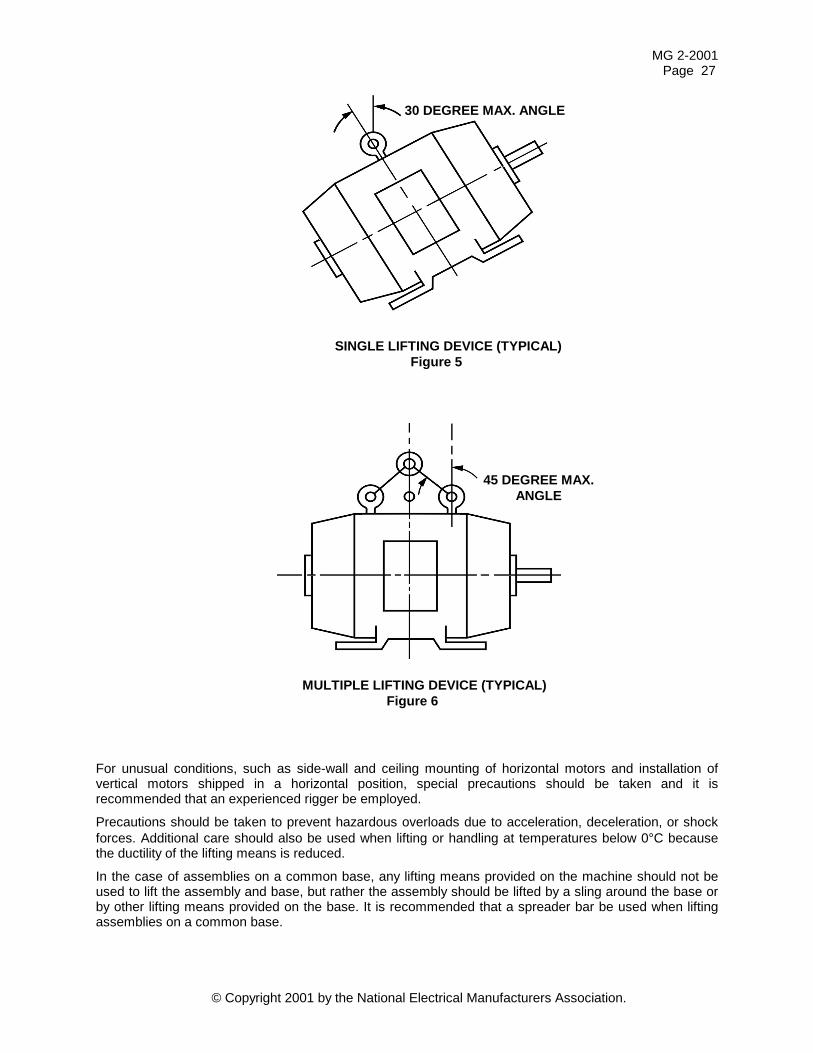
MG 2-2001 Page 27
© Copyright 2001 by the National Electrical Manufacturers Association.
For unusual conditions, such as side-wall and ceiling mounting of horizontal motors and installation of vertical motors shipped in a horizontal position, special precautions should be taken and it is recommended that an experienced rigger be employed.
Precautions should be taken to prevent hazardous overloads due to acceleration, deceleration, or shock forces. Additional care should also be used when lifting or handling at temperatures below 0°C because the ductility of the lifting means is reduced.
In the case of assemblies on a common base, any lifting means provided on the machine should not be used to lift the assembly and base, but rather the assembly should be lifted by a sling around the base or by other lifting means provided on the base. It is recommended that a spreader bar be used when lifting assemblies on a common base.
SINGLE LIFTING DEVICE (TYPICAL) Figure 5
MULTIPLE LIFTING DEVICE (TYPICAL) Figure 6
30 DEGREE MAX. ANGLE
45 DEGREE MAX. ANGLE
MG 2-2001 Page 28
© Copyright 2001 by the National Electrical Manufacturers Association.
Unless specifically allowed by the manufacturer's instruction manual or drawings, or both, the lifting means provided for lifting a machine should not be used to lift the machine plus additional equipment such as gears, pumps, compressors, or other driven equipment.
EXCEPTION: For machines built in 34-inch diameter1 (680 frame) and smaller, the following guide may be used:
If care is taken to minimize shock loading, and a spreader bar or supporting sling (securely anchored), or both, is used to assure a lifting force parallel with the designed lifting direction (lifting angle of zero degrees) and equally distributed over multiple lifting points, connected loads not exceeding 100 percent of the machine weight can normally be safely handled with the machine lifting device (see Figures 7, 8, and 9).
7.8 Surface Temperatures The surface temperature of machines varies with enclosure type, cooling method, insulation class, and operating conditions. Exposed surfaces may reach temperatures which could cause discomfort or injury to personnel accidentally coming in contact with the hot surfaces. For this reason during machine installation consideration should be given to the possible need to protect against accidental contact with hot machine surfaces.
7.9 Hold-down Bolt Sizes The bolt holes in machine feet and flanges have been selected to accept bolts which will hold the machine securely in place. The largest bolt diameter which will fit the nominal hole should be used to mount the machine. The length of the bolt should be such that the minimal thread engagement based on steel (or equivalent) is equal to the bolt diameter after allowing for washers under the head of the bolt and any shims under the feet.
7.10 Power Factor Correction When power factor correction capacitors are used, the total corrective kVAR placed on the load side of the motor controller should not exceed the value required to raise the no-load power factor of the motor to unity. Corrective kVAR in excess of this value may cause overexcitation resulting in high transient voltages, currents, and torques that can increase safety hazards to personnel and can cause possible damage to the motor or to the driven equipment.
The use of capacitors for power factor correction, switched at the motor terminals, is not recommended for elevator motors, multi-speed motors, motors used on plugging or jogging applications, motors subject to high speed bus transfer, and motors used with open transition wye-delta or auto-transformer starting. For such applications the motor manufacturer should be consulted before installing power factor corrective capacitors switched at the motor terminals.
1 This is a diameter measured in the plane of laminations of the circle circumscribing the stator frame, excluding
lugs, fins, boxes, and so forth, used solely for machine cooling, mounting, assembly, or connection.
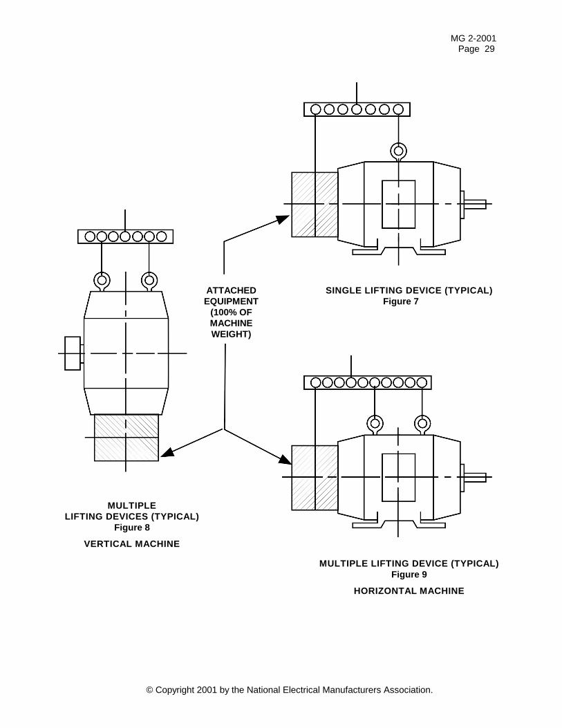
MG 2-2001 Page 29
© Copyright 2001 by the National Electric
LIFTING
VER
ATTACHED EQUIPMENT
(100% OF MACHINE WEIGHT)
MULTIPLE LIFTING DEVICE (TYPICAL) Figure 9
HORIZONTAL MACHINE
SINGLE LIFTING DEVICE (TYPICAL)Figure 7
MULTIPLE DEVICES (TYPICAL)
Figure 8
TICAL MACHINE
al Manufacturers Association.
MG 2-2001 Page 30
© Copyright 2001 by the National Electrical Manufacturers Association.
7.11 Starting Current in Induction Motors
7.11.1 Locked Rotor Current The proper selection and operation of motor branch circuit, short-circuit, and ground-fault protective devices, such as overload relays, instantaneous trip breakers, motor controllers, and fuses, require coordination with the level of motor rated locked rotor or inrush current. Limits on locked rotor current have been established for some NEMA Design B, C, and D and IEC Design N and H type induction motors as given in Table 4.
For medium ac induction motors the nameplate is marked with a code letter designating the ratio of kVA to horsepower at locked rotor for that particular design. The relationship between the code letter and kVA/hp is given in Table 5. When a motor is so marked, rather than using the limit given in Table 4 the maximum level of locked rotor current at rated voltage and frequency can be found by multiplying the upper limit on the range for the marked code letter by the rated horsepower times 1000 and dividing by the constant 1.732 times the rated line-to-line terminal voltage. For single-phase motors, multiply the upper limit on the range for the marked code letter by the rated horsepower times 1000 and divide by the rated voltage.
No limits on locked rotor current have been established for NEMA Design A motors. The manufacturer should be consulted for information on Design A motors and motors not covered by Table 4 for which a code letter has not been marked on the motor.
7.11.2 Instantaneous Peak Value of Inrush Current The values of locked rotor current given in Table 4 are the steady-state rms symmetrical values after any transients due to sudden application of line power at starting have decayed to negligible values. During the initial transient in each phase there will be a one-half cycle instantaneous peak value which may range from 1.8 to 2.8 times the steady-state value as a function of the motor design and the switching angle of the power system voltage in that phase. This is based on an assumed ambient temperature of 25oC.
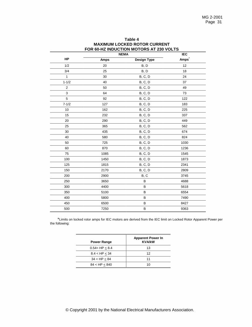
MG 2-2001 Page 31
© Copyright 2001 by the National Electrical Manufacturers Association.
Table 4 MAXIMUM LOCKED ROTOR CURRENT
FOR 60-HZ INDUCTION MOTORS AT 230 VOLTS NEMA
HP Amps Design Type IEC
Amps*
1/2 20 B, D 12 3/4 25 B, D 18 1 30 B, C, D 24
1-1/2 40 B, C, D 37 2 50 B, C, D 49 3 64 B, C, D 73 5 92 B, C, D 122
7-1/2 127 B, C, D 183 10 162 B, C, D 225 15 232 B, C, D 337 20 290 B, C, D 449 25 365 B, C, D 562 30 435 B, C, D 674 40 580 B, C, D 824 50 725 B, C, D 1030 60 870 B, C, D 1236 75 1085 B, C, D 1545 100 1450 B, C, D 1873 125 1815 B, C, D 2341 150 2170 B, C, D 2809 200 2900 B, C 3745 250 3650 B 4688 300 4400 B 5618 350 5100 B 6554 400 5800 B 7490 450 6500 B 8427 500 7250 B 9363
*Limits on locked rotor amps for IEC motors are derived from the IEC limit on Locked Rotor Apparent Power per
the following:
Power Range
Apparent Power In KVA/kW
0.54< HP < 8.4 13 8.4 < HP < 34 12 34 < HP < 84 11
84 < HP < 840 10
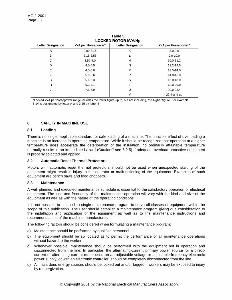
MG 2-2001 Page 32
© Copyright 2001 by the National Electrical Manufacturers Association.
Table 5 LOCKED ROTOR kVA/Hp
Letter Designation kVA per Horsepower* Letter Designation kVA per Horsepower*
A 0.00-3.15 K 8.0-9.0 B 3.15-3.55 L 9.0-10.0 C 3.55-4.0 M 10.0-11.2 D 4.0-4.5 N 11.2-12.5 E 4.5-5.0 P 12.5-14.0 F 5.0-5.6 R 14.0-16.0 G 5.6-6.3 S 16.0-18.0 H 6.3-7.1 T 18.0-20.0 J 7.1-8.0 U 20.0-22.4 V 22.4-and up
*Locked kVA per horsepower range includes the lower figure up to, but not including, the higher figure. For example, 3.14 is designated by letter A and 3.15 by letter B.
8. SAFETY IN MACHINE USE
8.1 Loading There is no single, applicable standard for safe loading of a machine. The principle effect of overloading a machine is an increase in operating temperature. While it should be recognized that operation at a higher temperature does accelerate the deterioration of the insulation, no ordinarily attainable temperature normally results in an immediate hazard (Caution see 6.2.5) if adequate overload protective equipment is properly selected and applied.
8.2 Automatic Reset Thermal Protectors Motors with automatic reset thermal protectors should not be used when unexpected starting of the equipment might result in injury to the operator or malfunctioning of the equipment. Examples of such equipment are bench saws and food choppers.
8.3 Maintenance A well planned and executed maintenance schedule is essential to the satisfactory operation of electrical equipment. The kind and frequency of the maintenance operation will vary with the kind and size of the equipment as well as with the nature of the operating conditions.
It is not possible to establish a single maintenance program to serve all classes of equipment within the scope of this publication. The user should establish a maintenance program giving due consideration to the installation and application of the equipment as well as to the maintenance instructions and recommendations of the machine manufacturer.
The following factors should be considered when formulating a maintenance program:
a) Maintenance should be performed by qualified personnel. b) The equipment should be so located as to permit the performance of all maintenance operations
without hazard to the worker. c) Whenever possible, maintenance should be performed with the equipment not in operation and
disconnected from the line. In particular, the alternating-current primary power source for a direct-current or alternating-current motor used on an adjustable-voltage or adjustable-frequency electronic power supply, or with an electronic controller, should be completely disconnected from the line.
d) All hazardous energy sources should be locked out and/or tagged if workers may be exposed to injury by reenergization.
MG 2-2001 Page 33
© Copyright 2001 by the National Electrical Manufacturers Association.
e) A general inspection of mechanical integrity, that is, fracture, loose bolts, missing parts, and so forth, should be made.
f) Vibration and noise should be observed. A change in the magnitude or frequency of the vibration or noise, or both, indicates a need for attention.
g) Ventilation passages should be kept open. If the equipment depends upon auxiliary cooling, that is, air, water, oil, and so forth, periodic inspections should be made of these systems.
h) Periodic inspection or tests, or both, of the insulation system, when recommended by the machine manufacturer, should be made.
i) Brushes, slip rings, and commutators should be frequently inspected and serviced as required. j) Lubrication procedures given in the machine manufacturer's instructions should be followed. k) The means employed for grounding the machine or insulating the machine from ground should be
checked to assure its integrity. l) Flexible cords and connectors should be examined to determine that the cords are free from abrasion,
cracks, and exposed strands and that the connectors have unbroken bodies so that live parts are not exposed.
8.4 Repair When a machine is repaired, it is important that any replacement part be of a quality equal to or better than that of the original part. For example, any replacement shaft should be of as high quality steel and have as good heat treatment as the shaft being replaced; insulation should be replaced by insulating materials of at least the same, or higher, temperature rating. Care should be taken to avoid the use of parts which no longer are compatible with other changes in the machine. Also, replacement parts should be inspected for deterioration due to shelf life and for signs of rework or wear which may involve factors critical to safety.
Repaired machines should conform to the provisions of this publication except that if a winding is only repaired or partially replaced, the applied high-potential test voltage should be 70 percent of the specified value.
MG 2-2001 Page 34
© Copyright 2001 by the National Electrical Manufacturers Association.