nellcor n5600 manual
TRANSCRIPT
SERVICE MANUAL
For N5600 Patient Monitor Tyco Healthcare 15 Hampshire Street Mansfield, MA02048, U.S.A. Tyco Healthcare EMEA (Europe, Middle East and Africa) Tyco Healthcare UK Ltd. 154 Fareham Road, Gosport PO13 0AS, U.K. EU Representative Tyco Healthcare UK Ltd. 154 Fareham Road, Gosport PO13 0AS, U.K. Tel: (44) 1 329 224 114 Fax: (44) 1 329 224 390 Manufactured for Tyco Healthcare Mansfield, MA 02048, U.S.A. Manufactured by Mediana Co., Ltd. Wonju Medical Industry Park, 1650-1 Donghwa-ri, Munmak-eup, Wonju-si, Gangwon-do, Korea Copyright © 2006 Tyco Healthcare. All rights reserved.
Notice This document contains proprietary information which is protected by copyright. All Rights Reserved. Reproduction, adaptation, or translation without prior written permission is prohibited, except as allowed under the copyright laws. Warranty The information contained in this document is subject to change without notice. Tyco Healthcare makes no warranty of any kind with regard to this material, including, but not limited to, the implied warranties or merchantability and fitness for a particular purpose. Tyco Healthcare shall not be liable for errors contained herein or for incidental or consequential damages in connection with the furnishing, performance, or use of this material. Revision/Printing History The documentation printing date and part number indicate its current edition. The printing date changes when a new edition is printed in accordance with the revision history of the documentation. Minor corrections and updates which are incorporated at reprint do not cause the date to change. The document part number changes when extensive technical changes are incorporated.
Contents
Figures Tables
N5600 Service Manual i
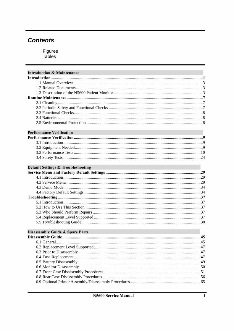
Introduction & Maintenance Introduction................................................................................................................................................1
1.1 Manual Overview ..........................................................................................................................3 1.2 Related Documents ........................................................................................................................3 1.3 Description of the N5600 Patient Monitor ....................................................................................3
Routine Maintenance.................................................................................................................................7 2.1 Cleaning .........................................................................................................................................7 2.2 Periodic Safety and Functional Checks .........................................................................................7 2.3 Functional Checks..........................................................................................................................8 2.4 Batteries .........................................................................................................................................8 2.5 Environmental Protection ..............................................................................................................8
Performance Verification Performance Verification..........................................................................................................................9
3.1 Introduction....................................................................................................................................9 3.2 Equipment Needed.........................................................................................................................9 3.3 Performance Tests ........................................................................................................................10 3.4 Safety Tests ..................................................................................................................................24
Default Settings & Troubleshooting Service Menu and Factory Default Settings ..........................................................................................29
4.1 Introduction..................................................................................................................................29 4.2 Service Menu ...............................................................................................................................29 4.3 Demo Mode .................................................................................................................................34 4.4 Factory Default Settings...............................................................................................................34
Troubleshooting .......................................................................................................................................37 5.1 Introduction..................................................................................................................................37 5.2 How to Use This Section .............................................................................................................37 5.3 Who Should Perform Repairs ......................................................................................................37 5.4 Replacement Level Supported .....................................................................................................37 5.5 Troubleshooting Guide.................................................................................................................38
Disassembly Guide & Spare Parts Disassembly Guide...................................................................................................................................45
6.1 General.........................................................................................................................................45 6.2 Replacement Level Supported .....................................................................................................47 6.3 Prior to Disassembly....................................................................................................................47 6.4 Fuse Replacement........................................................................................................................47 6.5 Battery Disassembly ....................................................................................................................49 6.6 Monitor Disassembly...................................................................................................................50 6.7 Front Case Disassembly Procedures............................................................................................51 6.8 Rear Case Disassembly Procedures .............................................................................................56 6.9 Optional Printer Assembly/Disassembly Procedures...................................................................65
Contents
ii N5600 Service Manual
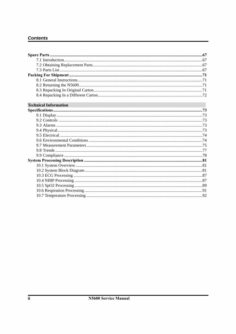
Spare Parts ...............................................................................................................................................67 7.1 Introduction..................................................................................................................................67 7.2 Obtaining Replacement Parts.......................................................................................................67 7.3 Parts List ......................................................................................................................................67
Packing For Shipment .............................................................................................................................71 8.1 General Instructions.....................................................................................................................71 8.2 Returning the N5600....................................................................................................................71 8.3 Repacking In Original Carton......................................................................................................71 8.4 Repacking In a Different Carton..................................................................................................72
Technical Information Specifications............................................................................................................................................73
9.1 Display.........................................................................................................................................73 9.2 Controls .......................................................................................................................................73 9.3 Alarms .........................................................................................................................................73 9.4 Physical........................................................................................................................................73 9.5 Electrical ......................................................................................................................................74 9.6 Environmental Conditions ...........................................................................................................74 9.7 Measurement Parameters.............................................................................................................75 9.8 Trends ..........................................................................................................................................77 9.9 Compliance ..................................................................................................................................78
System Processing Description ...............................................................................................................81 10.1 System Overview .......................................................................................................................81 10.2 System Block Diagram ..............................................................................................................81 10.3 ECG Processing .........................................................................................................................87 10.4 NIBP Processing ........................................................................................................................87 10.5 SpO2 Processing ........................................................................................................................89 10.6 Respiration Processing...............................................................................................................91 10.7 Temperature Processing .............................................................................................................92

Contents
N5600 Service Manual iii
Figures Figure 1. N5600 Front Panel.......................................................................................................................................................... 4 Figure 2. N5600 Rear Panel ........................................................................................................................................................... 5 Figure 3. N5600 Right Side Panel .................................................................................................................................................. 6 Figure 4. N5600 Left Side Panel..................................................................................................................................................... 6 Figure 5. The access of Service Menu via Set-up menu ................................................................................................................ 29 Figure 6. Service Menu................................................................................................................................................................. 30 Figure 7. Disassembly Sequence Flow Chart ............................................................................................................................... 46 Figure 8. N5600 Exploded View ................................................................................................................................................... 68 Figure 9. N5600 System Block Diagram 1.................................................................................................................................... 81 Figure 10. N5600 System Block Diagram 2.................................................................................................................................. 82 Figure 11. N5600 System Block Diagram 3 .................................................................................................................................. 82 Figure 12. Power Unit Block Diagram......................................................................................................................................... 83 Figure 13. Process Unit Block Diagram....................................................................................................................................... 83 Figure 14. User-Control Unit Block Diagram .............................................................................................................................. 83 Figure 15. Sound Unit Block Diagram ......................................................................................................................................... 84 Figure 16. Communication Unit Block Diagram.......................................................................................................................... 84 Figure 17. GUI Unit Block Diagram ............................................................................................................................................ 84 Figure 18. Thermal Printer Unit Block Diagram.......................................................................................................................... 84 Figure 19. NIBP Unit Block Diagram .......................................................................................................................................... 85 Figure 20. ECG Unit Block Diagram ........................................................................................................................................... 85 Figure 21. Respiration Unit Block Diagram................................................................................................................................. 85 Figure 22. SpO2 Unit Block Diagram .......................................................................................................................................... 85 Figure 23. Temperature Unit Block Diagram ............................................................................................................................... 86 Figure 24. Analog Control Unit Block Diagram........................................................................................................................... 86 Figure 25. Oxyhemoglobin Dissociation Curve............................................................................................................................ 90 Tables Table 1. Required Test Equipments ................................................................................................................................................. 9 Table 2. Parameter Alarm Limit Factory Defaults........................................................................................................................ 14 Table 3. Earth Leakage Current Values ........................................................................................................................................ 25 Table 4. Enclosure Leakage Current............................................................................................................................................. 25 Table 5. Patient Leakage Current Values ...................................................................................................................................... 26 Table 6. Patient Leakage Current Values—Mains Voltage on Applied Part.................................................................................. 27 Table 7. Test Lead Combinations .................................................................................................................................................. 28 Table 8. Allowable Leakage Current............................................................................................................................................. 28 Table 9. Service menu ................................................................................................................................................................... 31 Table 10. NIBP Test Mode............................................................................................................................................................. 33 Table 11. System Information........................................................................................................................................................ 33 Table 12. Factory Default Settings for the N5600......................................................................................................................... 34 Table 13. Problem Categories....................................................................................................................................................... 38 Table 14. Power Problems ............................................................................................................................................................ 39 Table 15. Display .......................................................................................................................................................................... 40 Table 16. Switches/Knob Problems ............................................................................................................................................... 41 Table 17. Alarms/Audible Tones Problems.................................................................................................................................... 41 Table 18. Operational Performance Problems.............................................................................................................................. 42 Table 19. Technical Error Codes................................................................................................................................................... 43 Table 20. N5600 Parts List ........................................................................................................................................................... 69

Contents
iv N5600 Service Manual
This page is intentionally left blank.
Section 1: Introduction
1.1 Manual Overview 1.2 Related Documents 1.3 Description of the N5600 Patient Monitor
N5600 Service Manual 1
Introduction and
Maintenance, N
5600
Warnings
Warnings are identified by the WARNING symbol shown above. Warnings alert the user to potential serious outcomes (death, injury, or adverse events) to the patient or user.
WARNING: Explosion hazard. Do not use the N5600 in the presence of flammable anesthetics or gases.
WARNING: Do not spray, pour, or spill any liquid on the N5600, its accessories, connectors, switches, or openings in the chassis.
WARNING: Do not immerse the N5600 or its accessories in liquid or clean with caustic or abrasive cleaners.
WARNING: Ensure that conductive portions of the electrodes, leads, and cable do not come into contact with any other conductive parts.
WARNING: Before attempting to open or disassemble the N5600, disconnect the power cord from the N5600
WARNING: The LCD panel contains toxic chemicals. Do not ingest chemicals from a broken LCD panel.
WARNING: The use of accessories, transducers, and cables other than those specified may result in increased emission and/or decreased immunity of the N5600 patient monitor.
WARNING: Do not silence the N5600 audible alarm or decrease its volume if patient safety could be compromised.
Introduction
2 N5600 Service Manual
In
trod
uctio
n an
d M
aint
enan
ce, N
5600
WARNING: During the safety test, AC mains voltage will be present on the applied part terminals. Exercise caution to avoid electrical shock hazard.
WARNING: Do not place the N5600 into operation after repair or maintenance has been performed, until all Performance Tests and Safety Tests listed in section 3 of this service manual have been performed. Failure to perform all tests could result in erroneous monitor readings.
WARNING: High voltage is generated by the LCD backlight driver. Exercise caution when operating monitor with covers open..
Cautions
Cautions are identified by the Caution symbol shown above. Cautions alert the user to exercise care necessary for the safe and effective use of the N5600 monitor. CAUTION: Observe ESD (electrostatic discharge) precautions when working within the unit and/or when disassembling and reassembling the N5600 patient monitor and when handling any of the components of the N5600 patient monitor. CAUTION: When reassembling the N5600, over-tightening could strip out the screw holes in the cases, rendering it unusable. CAUTION: If any problem with N5600 built in an optional printer, check a printer’s door is closed well. Operating error may be caused if the cover is not closed correctly. CAUTION: If internal battery cable has been disconnected, pay particular attention to polarity of the cable before reattaching. If battery cable polarity is reversed, it is likely that circuit damage will occur. CAUTION: Ferrite Cores are used for electromagnetic compatibility. Please do not remove Ferrite Cores while disassembling or reassembling, otherwise the monitor can be affected by electromagnetic interference and measure inaccurate data to be displayed or stored. CAUTION: When reassembling, never forget that one of four screws on the back bracket must be connected to green ground cable of the power inlet. This method is for protecting dormant electrical shock hazards to operator or service engineer.

Introduction
N5600 Service Manual 3
Introduction and
Maintenance, N
5600
1.1 Manual Overview This manual contains information for servicing the N5600 patient monitor. The monitor subsequently referred to as N5600 throughout this manual. Only qualified service personnel should service this product. Before servicing the N5600, read the operator’s manual carefully for a thorough understanding of safe operation. Read and understand all safety warnings and service notes printed in this service manual and the operator’s manual part number A7008.
1.2 Related Documents
To perform test and troubleshooting procedures and to understand the principles of operation and circuit analysis sections of this manual, you must know how to operate the monitor. Refer to the N5600 operator’s manual part number A7008. To understand the various Nellcor sensors, ECG leads, blood pressure cuffs, and temperature probes that work with the monitor, refer to the individual directions for use that accompany these accessories.
1.3 Description of the N5600 Patient Monitor
The purpose and function of the Nellcor N5600 patient monitor is to monitor ECG, heart rate, noninvasive blood pressure (systolic, diastolic, and mean arterial pressures), functional arterial oxygen saturation, pulse rate, respiration, and temperature for adult, pediatric and neonate patients in all hospital areas and hospital-type facilities. It is not intended for home use. Monitor users should be skilled at the level of a technician, doctor, nurse or medical specialist. Note: Hospital use typically covers such areas as general care floors, operating rooms,
special procedure areas, intensive and critical care areas, within the hospital plus hospital-type facilities. Hospital-type facilities include physician office based facilities, sleep labs, skilled nursing facilities, surgicenters, and sub-acutecenters.
Note: The N5600 patient monitor is not intended to monitor animal vital conditions.

Introduction
4 N5600 Service Manual
In
trod
uctio
n an
d M
aint
enan
ce, N
5600
The physical and operational characteristics of the monitor are described in the operator’s manual and in the Specifications section of this manual.
Figure 1 and 2 identify the displays, controls, indicators and symbols of the front and rear panels.
1. Waveform Display Icon 14. Home Switch 2. Graphic Frame 15. Date and Time Display 3. Message Frame 16. Alarm Silence/Suspend Switch 4. Set-up Icon 17. Knob Switch 5. Alarm/Limits Icon 18. Low Battery Indicator 6. Big Numbers Icon 19. Battery Charging/ AC Power Indicator7. NIBP Start/Stop Switch 20. Pulse Amplitude Indicator 8. Power On/Off Icon 21. Numeric Value Display 9. Power On/Off Button 22. SatSeconds Indicator 10. Power On/Off Indicator 23. Numeric Frame 11. Record Switch 24. Numeric Display Icon 12. Battery Icon 25. Alarm Indicator 13. Patient Mode Display
Figure 1. N5600 Front Panel
12
345
6 7 8 9 10 11 12 13 14 15 16 17 18 19 20
120
140/100(120)
mmHg
/min
T1
T2
24
%SpO2
SpO2
1.0 cmmV
/min
21 22
180
120
100
140/100(120)
RR
T1
T2
24
SpO2
SpO2
1mV
ECG
HR
37.0
180
ECG
Resp
NIBP
C
F06/12/2002 08:12:23Adult
23 24
25
Introduction
N5600 Service Manual 5
Introduction and
Maintenance, N
5600
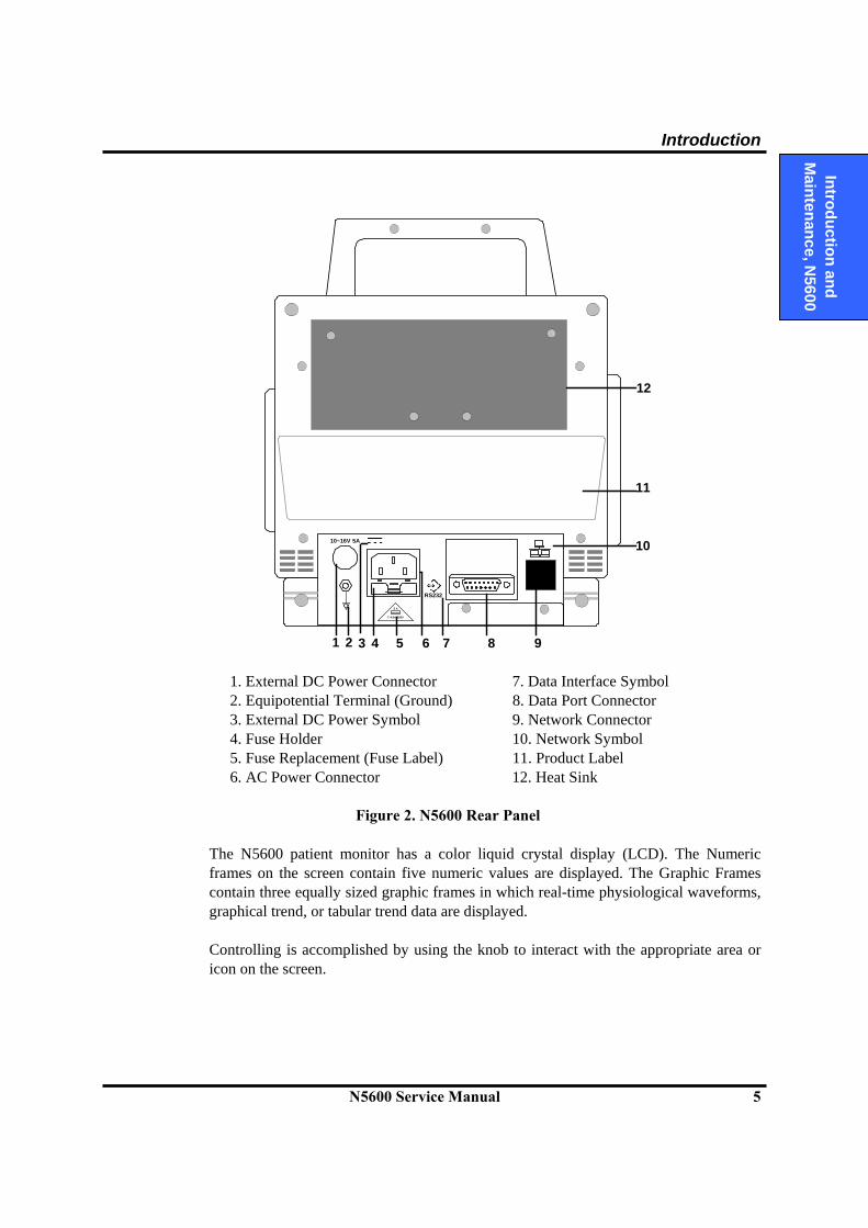
1. External DC Power Connector 7. Data Interface Symbol 2. Equipotential Terminal (Ground) 8. Data Port Connector 3. External DC Power Symbol 9. Network Connector 4. Fuse Holder 10. Network Symbol 5. Fuse Replacement (Fuse Label) 11. Product Label 6. AC Power Connector 12. Heat Sink
Figure 2. N5600 Rear Panel
The N5600 patient monitor has a color liquid crystal display (LCD). The Numeric frames on the screen contain five numeric values are displayed. The Graphic Frames contain three equally sized graphic frames in which real-time physiological waveforms, graphical trend, or tabular trend data are displayed. Controlling is accomplished by using the knob to interact with the appropriate area or icon on the screen.
2 X
T 4.0A 250V
RS232
10~16V 5A
12
1 2 3 4 5 7 86 9
10
11
Introduction
6 N5600 Service Manual
In
trod
uctio
n an
d M
aint
enan
ce, N
5600
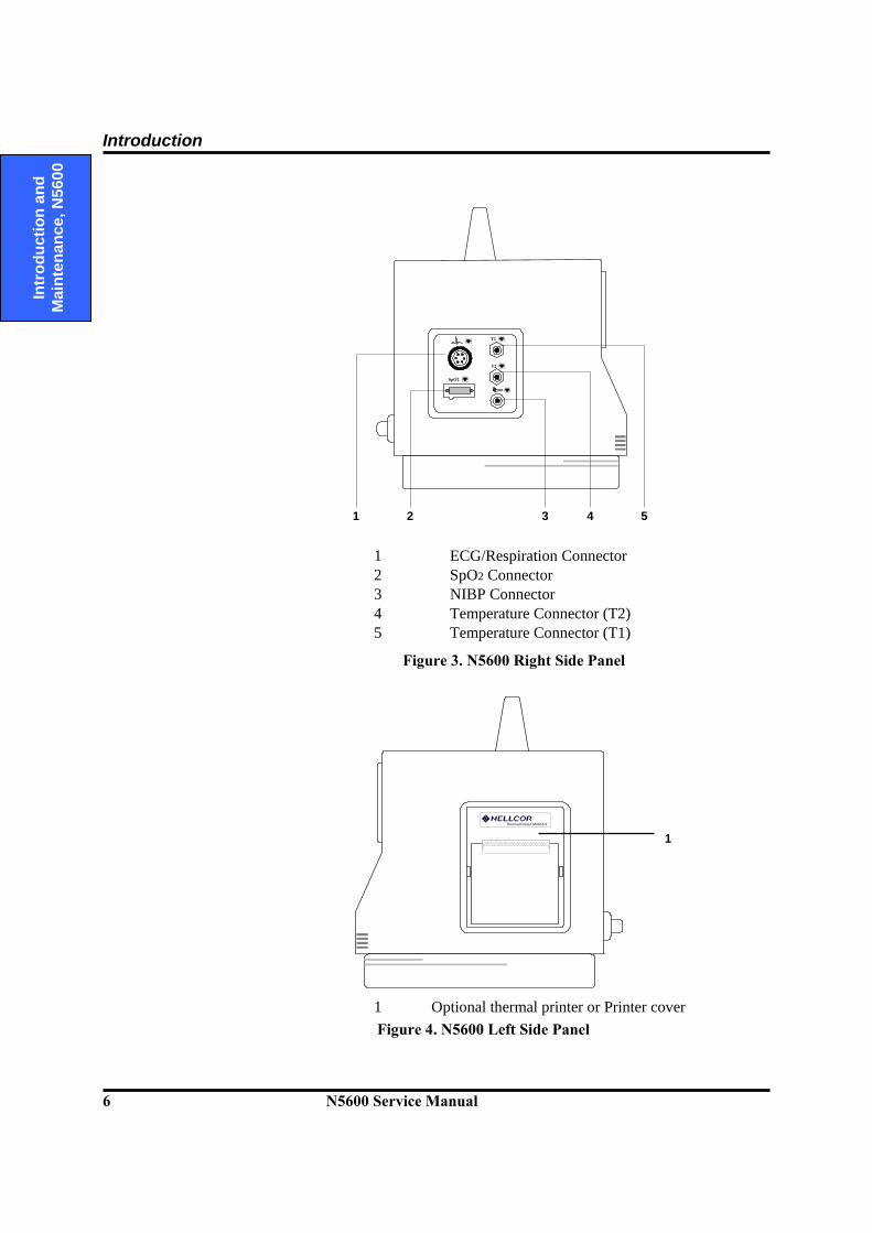
1 ECG/Respiration Connector 2 SpO2 Connector 3 NIBP Connector 4 Temperature Connector (T2) 5 Temperature Connector (T1)
Figure 3. N5600 Right Side Panel
Thermal Printer M4014-0
1 Optional thermal printer or Printer cover Figure 4. N5600 Left Side Panel
T2
T1
SpO2
1 2 3 4 5
1

Section 2: Routine Maintenance
2.1 Cleaning 2.2 Periodic Safety and Functional Checks 2.3 Functional Checks 2.4 Batteries 2.5 Environmental Protection
N5600 Service Manual 7
Introduction and
Maintenance, N
5600
WARNING: Do not spray or pour any liquid on the monitor or its accessories. Do not immerse the N5600 or its accessories in liquid or clean with caustic or abrasive cleaners.
2.1 Cleaning
To clean the N5600, dampen a cloth with a commercial, nonabrasive cleaner and wipe the exterior surfaces lightly. CAUTION: Do not allow any liquids to come in contact with the power connector or switches or to penetrate connectors or openings in the instrument. Note: For cables, sensors and cuffs, follow the cleaning instructions in the directions
for use that accompany these accessories. Note: If liquid is spilled on the monitor, clean and dry thoroughly before reuse. Note: If in doubt about monitor safety, refer the unit to qualified service personnel. For surface-cleaning, follow your institution’s procedures or:
The N5600 may be surface-cleaned by using a soft cloth dampened with either a commercial, nonabrasive cleaner or a solution of 70% alcohol in water, and lightly wiping the top, bottom, and front surfaces of the monitor lightly.
2.2 Periodic Safety and Functional Checks
The N5600 requires no routine service or calibration other than cleaning and battery maintenance. The following performance verification tests may be used following repair or during routine maintenance (if required by your local institution). 1. Inspect the exterior of the N5600 for damage.
2. Inspect labels for legibility. If the labels are not legible, contact Tyco Healthcare
Technical Services Department or your local Tyco Healthcare representative. 3. Verify that the unit performs properly as described in Performance Verification
section.
Routine Maintenance
8 N5600 Service Manual
In
trod
uctio
n an
d M
aint
enan
ce, N
5600
4. Perform the electrical safety tests detailed in Performance Verification section. If the unit fails these electrical safety tests, do not attempt to repair. Contact Tyco Healthcare Technical Services Department or your local Tyco Healthcare representative.
2.3 Functional Checks
The following checks should be performed at least every 2 years by a qualified service technician. 1. If the monitor has been visibly damaged or subjected to mechanical shock (for
example, if dropped), perform the performance tests as described in Performance Verification section.
2. Perform the electrical safety tests as described in Safety Tests section. If the unit
fails these electrical safety tests, refer to Troubleshooting section. 3. Inspect the fuses for proper value and rating (qty 2, 4.0 A, 250 volts).
2.4 Batteries If the N5600 has not been used for a long period of time, the battery will need charging. To charge the battery, connect the N5600 to an AC outlet as described in Paragraph 3.3.1 in this service manual or the Battery Operation section of the operator’s manual. Tyco Healthcare recommends replacing the instrument’s battery every 2 years. When the N5600 is going to be stored for 2 months or more, it is recommended to remove the battery prior to storage. To replace or remove the battery, refer to Disassembly Guide. Note: Storing the N5600 for a long period without charging the battery may degrade the
battery capacity. The battery may require a full charge/discharge cycle to restore normal capacity. Tyco Healthcare recommends that the N5600’s sealed, Ni-MH batteries be replaced at 2-year intervals. Refer to Disassembly Guide Section.
Note: The battery cannot be charged by an external DC power source.
2.5 Environmental Protection
Follow local governing ordinances and recycling plans regarding disposal or recycling batteries and other device components.
Section 3: Performance Verification
3.1 Introduction 3.2 Equipment Needed 3.3 Performance Tests 3.4 Safety Tests
N5600 Service Manual 9
Perform
ance Verification, N
5600
3.1 Introduction
This section discusses the tests used to verify performance following repairs or during routine maintenance. All tests can be performed without removing the N5600 covers. All tests except the battery charge and battery performance tests must be performed as the last operation before the monitor is returned to the user. If the N5600 fails to perform as specified in any test, repairs must be made to correct the problem before the monitor is returned to the user.
3.2 Equipment Needed
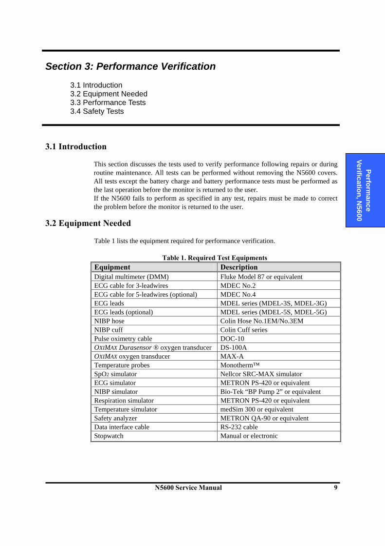
Table 1 lists the equipment required for performance verification.
Table 1. Required Test Equipments
Equipment Description Digital multimeter (DMM) Fluke Model 87 or equivalent ECG cable for 3-leadwires MDEC No.2 ECG cable for 5-leadwires (optional) MDEC No.4 ECG leads MDEL series (MDEL-3S, MDEL-3G) ECG leads (optional) MDEL series (MDEL-5S, MDEL-5G) NIBP hose Colin Hose No.1EM/No.3EM NIBP cuff Colin Cuff series Pulse oximetry cable DOC-10 OXIMAX Durasensor ® oxygen transducer DS-100A OXIMAX oxygen transducer MAX-A Temperature probes Monotherm™ SpO2 simulator Nellcor SRC-MAX simulator ECG simulator METRON PS-420 or equivalent NIBP simulator Bio-Tek “BP Pump 2” or equivalent Respiration simulator METRON PS-420 or equivalent Temperature simulator medSim 300 or equivalent Safety analyzer METRON QA-90 or equivalent Data interface cable RS-232 cable Stopwatch Manual or electronic

Performance Verification
10 N5600 Service Manual
Pe
rfor
man
ce
Verif
icat
ion,
N56
00
3.3 Performance Tests The battery charge and battery performance test should be performed before monitor repairs whenever the battery is suspected as being a source of the problems. All other tests may be used following repairs or during routine maintenance (if required by your local institution). Before performing the battery performance test, ensure that the battery is fully charged. This section is written using the factory power-up defaults. If your institution has preconfigured custom defaults, those values will be displayed.
3.3.1 Battery Charge 1. Connect monitor to AC power source using proper power cord. 2. Verify AC Power indicator is lit. 3. Charge battery fully for at least 18 hours. 4. The only way to check for a full charge is to perform the procedure in paragraph
3.3.2 “Battery Performance Test.” Note: The battery may require a complete charge/discharge cycle to restore its normal
capacity, depending on its previous usage.
3.3.2 Battery Performance Test 1. The N5600 monitor is specified to typically operate on battery power a minimum of
1 hour, at 25°C, with no printing, and one NIBP measurement every 5 minutes. Before performing this test, ensure that the battery is fully charged (paragraph 3.3.1).
2. Ensure monitor is not connected to AC power.
3. With N5600 turned off, press the Power On/Off switch and verify battery icon
appears at bottom of display after power-on self-test is completed. Boxes in battery icon should all be filled, indicating battery is charged.
4. Connect Nellcor SRC-MAX SpO2 simulator to monitor via DOC-10 sensor cable. 5. Connect NIBP simulator to monitor via Colin-NO.EM hose. 6. Set SRC-MAX as follows: SpO2 of 75% and pulse rate of 60 bpm.
7. Set NIBP simulator to simulate pressure setting of 120/80 mmHg and heart rate of 80
bpm. 8. Verify monitor is responding to SpO2 simulator signal and audible alarm is sounding.
Use knob to select SpO2 Menu and silence SpO2 audible alarm (SpO2 alarm suspend condition).

Performance Verification
N5600 Service Manual 11
Perform
ance Verification, N
5600
9. Use knob to select NIBP Menu and set Automatic Mode Interval to 5 minutes. Initial NIBP measurement will be automatically taken in 5 minutes, then subsequent NIBP measurements will be taken for 5 minutes, Automatic Mode Interval (from one measurement completes to the next measurement starts).
10. N5600 monitor must operate for 1 hour with a full-charged battery. N5600 monitor
must operate for at least 5 minutes before monitor automatically powers down due to low battery condition.
11. Verify low battery alarm occurs and the low battery indicator is lit about 5 minutes
before battery fully discharges. 12. Allow monitor to operate until it automatically powers down due to low battery
condition. Verify high priority alarm occurs 15 seconds before monitor automatically shuts down.
13. If monitor passes this test, immediately recharge battery (3.3.1 Battery Charge).
3.3.3 Power-On Self-Test 1. Connect monitor to AC power source and verify AC Power indicator is lit. 2. Observe monitor front panel. With monitor off, press Power On/Off switch. Monitor
must perform the following sequence. a. Monitor emits three consecutively higher pitched beeps. b. Nellcor logo appears for a few seconds, with version numbers of the software
displayed in lower left corner of display. c. Alarm Indicator (red) on the top of the front panel, AC power indicator
(green) and Low battery indicator (green) on the right bottom of the front panel are illuminated.
d. Upon successful completion of power-on self-test, display will be in normal monitoring screen configuration.
Note: Power-on self-test takes approximately 3 seconds to complete. Note: No vital signs numeric values or waveforms will be displayed.
3.3.4 General Operation Tests 3.3.4.1 Alarms and Alarm Silence
1. Press monitor Power On/Off switch to turn monitor on. 2. Connect SRC-MAX SpO2 simulator to sensor input cable and connect cable to
monitor. 3. Set SRC-MAX as follows: SpO2 of 75% and pulse rate of 60 bpm.
Performance Verification
12 N5600 Service Manual
Pe
rfor
man
ce
Verif
icat
ion,
N56
00
4. Verify following monitor reaction:
a. Pulse bar begins to track artificial pulse signal from SRC-MAX. b. After about 10 to 20 seconds, monitor displays saturation and pulse rate as
specified by simulator. Verify values are within following tolerances: Tolerance of Oxygen Saturation : ±2 % SpO2 Tolerance of Pulse Rate : ±3 bpm
c. Audible alarm sounds and “Low SpO2 limits violated” message will be displayed and % SpO2 numeric area will flash, indicating the parameter has violated default alarm limits.
5. Press Alarm silence/suspend switch on monitor front panel. Audible alarm is
temporarily silenced. 6. Verify the following:
a. An audible alarm remains silenced. b. Alarm silence icon appears in each numeric frame on display. c. %SpO2 display continues flashing. d. Audible alarm returns in approximately 60 seconds.
3.3.4.2 QRS Volume Control
1. Press monitor Power On/Off switch to turn monitor on. 2. Connect SRC-MAX SpO2 simulator to sensor input cable and connect cable to
monitor. 3. Set SRC-MAX as follows: SpO2 of 75% and pulse rate of 60 bpm.
4. Verify SpO2 and pulse rate values are correctly displayed. 5. Press Alarm silence/suspend switch on front panel of the monitor to temporarily
silence audible alarm. 6. Verify heart rate tone source, found in ECG Menu, is set to “SpO2”. 7. Select Setup icon on the screen to display Set-up menu. 8. Rotate knob to highlight QRS volume on Set-up menu and press knob to adjust QRS
volume.
9. Set QRS volume 1 to 7 and return to the monitoring screen. Verify beeping pulse rate tone increases.
10. Set QRS volume 7 to 1 and return to the monitoring screen. Verify beeping pulse
rate tone decreases.
Performance Verification
N5600 Service Manual 13
Perform
ance Verification, N
5600
11. Set QRS volume to Off and return to the monitoring screen. Verify beeping pulse rate tone is no longer audible.
12. Return QRS volume to a comfortable level.
3.3.4.3 LED Excitation Test This procedure uses normal system components to test circuit operation. A Nellcor OXIMAX oxygen transducer, model MAX-A, is used to examine LED intensity control. The red LED is used to verify intensity modulation caused by the LED intensity control circuit. 1. Connect the monitor to an AC power source. 2. Press the Power On/Off switch to turn the monitor on. 3. Connect DOC-10 pulse oximetry cable to the monitor. 4. Connect a MAX-A sensor to the pulse oximetry cable.
5. Leave the sensor open with the LEDs and photo detector visible. 6. After monitor completes its normal power-up sequence, verify that the sensor LED is
brightly lit. 7. Slowly move sensor LED in proximity of photodetector element of the sensor (close
the sensor slowly). Verify; as LED approaches the optical sensor, that the LED intensity decreases.
8. Open the sensor and notice that the LED intensity increases. 9. Repeat step 7 and intensity will again decrease. This variation is an indication that
the microprocessor is in proper control of LED intensity. 10. Press the Power On/Off switch to turn the N5600 monitor off.
Performance Verification
14 N5600 Service Manual
Pe
rfor
man
ce
Verif
icat
ion,
N56
00
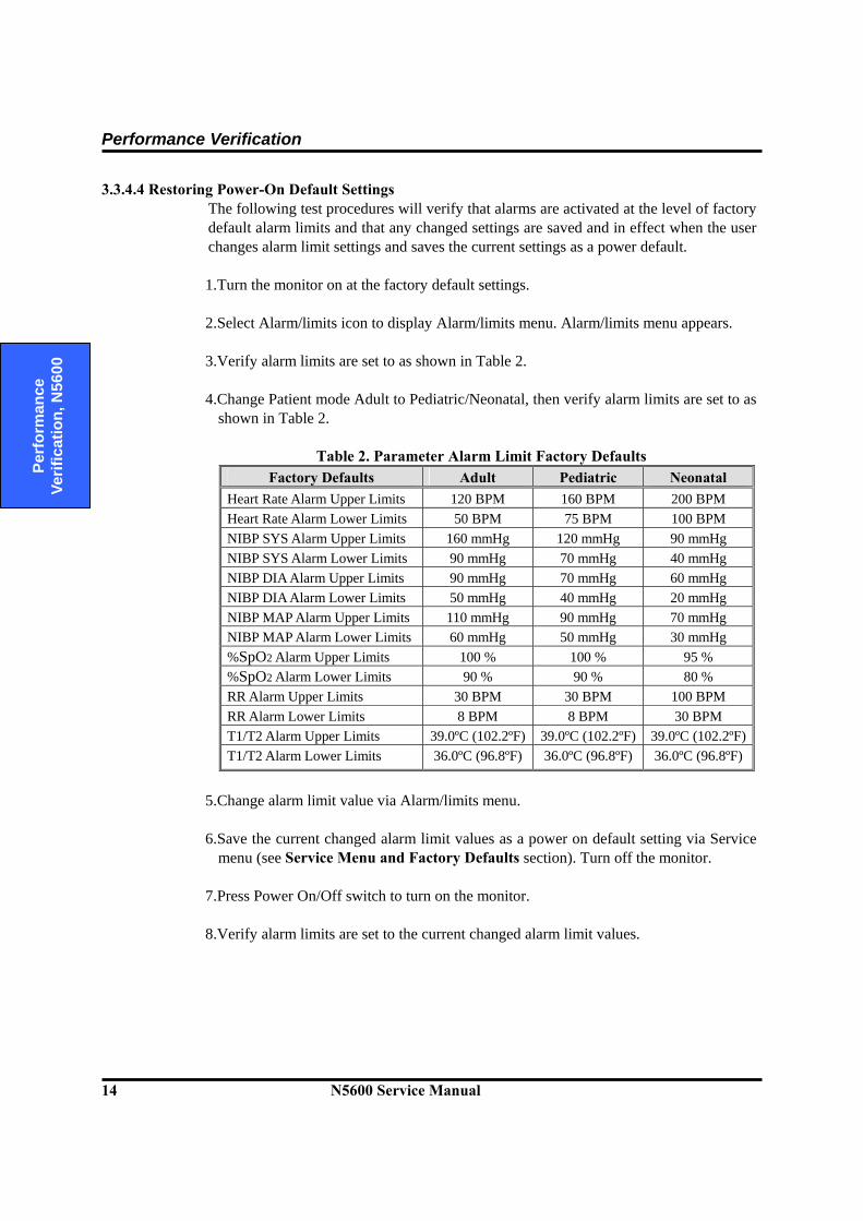
3.3.4.4 Restoring Power-On Default Settings The following test procedures will verify that alarms are activated at the level of factory default alarm limits and that any changed settings are saved and in effect when the user changes alarm limit settings and saves the current settings as a power default. 1.Turn the monitor on at the factory default settings. 2.Select Alarm/limits icon to display Alarm/limits menu. Alarm/limits menu appears.
3.Verify alarm limits are set to as shown in Table 2.
4.Change Patient mode Adult to Pediatric/Neonatal, then verify alarm limits are set to as
shown in Table 2.
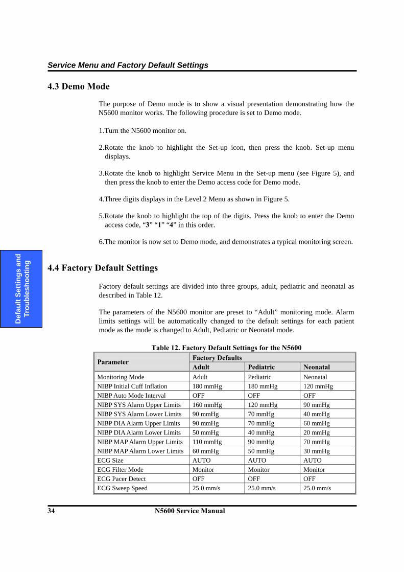
Table 2. Parameter Alarm Limit Factory Defaults Factory Defaults Adult Pediatric Neonatal
Heart Rate Alarm Upper Limits 120 BPM 160 BPM 200 BPM Heart Rate Alarm Lower Limits 50 BPM 75 BPM 100 BPM NIBP SYS Alarm Upper Limits 160 mmHg 120 mmHg 90 mmHg NIBP SYS Alarm Lower Limits 90 mmHg 70 mmHg 40 mmHg NIBP DIA Alarm Upper Limits 90 mmHg 70 mmHg 60 mmHg NIBP DIA Alarm Lower Limits 50 mmHg 40 mmHg 20 mmHg NIBP MAP Alarm Upper Limits 110 mmHg 90 mmHg 70 mmHg NIBP MAP Alarm Lower Limits 60 mmHg 50 mmHg 30 mmHg %SpO2 Alarm Upper Limits 100 % 100 % 95 % %SpO2 Alarm Lower Limits 90 % 90 % 80 % RR Alarm Upper Limits 30 BPM 30 BPM 100 BPM RR Alarm Lower Limits 8 BPM 8 BPM 30 BPM T1/T2 Alarm Upper Limits 39.0ºC (102.2ºF) 39.0ºC (102.2ºF) 39.0ºC (102.2ºF)T1/T2 Alarm Lower Limits 36.0ºC (96.8ºF) 36.0ºC (96.8ºF) 36.0ºC (96.8ºF)
5.Change alarm limit value via Alarm/limits menu.
6.Save the current changed alarm limit values as a power on default setting via Service
menu (see Service Menu and Factory Defaults section). Turn off the monitor.
7.Press Power On/Off switch to turn on the monitor.
8.Verify alarm limits are set to the current changed alarm limit values.
Performance Verification
N5600 Service Manual 15
Perform
ance Verification, N
5600
3.3.4.5 Printer Testing (Option) If an optional printer is installed in the N5600 monitor, the following test procedures will verify the printer performance. 1. Turn the monitor on. 2. Connect all the necessary parameter simulators to the monitor. 3. Select Set-up icon to display Set-up menu. Set-up menu appears. 4. Test #1: One-shot printing
i. Set Print mode to One-shot. ii. Press Record switch when all the parameter signals display normally.
iii. Verify the parameter values and waveforms are printed out for 20 seconds. 5. Test #2: Continuous printing
i. Set Print mode to Continuous. ii. Press Record switch when all the parameter signals display normally.
iii. Verify the parameter values and waveforms are printed out continuously. iv. Verify printing stops with pressing Record switch again.
6. Test #3: Print speed
i. Set Print speed to 25 mm/s. ii. Press Record switch when all the parameter signals display normally.
iii. Verify the parameter values and waveforms are printed out with 25 mm/s. iv. Verify printing stops with pressing Record switch again. v. Set Print speed to 50 mm/s.
vi. Press Record switch when all the parameter signals display normally. vii. Verify the parameter values and waveforms are printed out with 50 mm/s.
viii. Verify printing stops with pressing Record switch again. 7. Test #4: Print-on-alarm
i. Select Alarm/limits icon to display alarm/limits menu. Alarm/limits menu appears.
ii. Set Print-on-alarm to ON in the Alarm/limits menu. iii. Set Hear rate of ECG simulator to 30 bpm. iv. Verify Heart rate low limits violated alarm is activated and the parameter
values and waveforms are printed out. Note: If no printer is installed in the N5600 monitor, Print mode and Print speed will
not display in the Set-up menu. Note: If there is no printer paper left or printer paper places improperly, the monitor
will display an error message and activate low priority alarm. Note: If an optional printer connection is improper, the monitor will display an error
message and activate low priority alarm.

Performance Verification
16 N5600 Service Manual
Pe
rfor
man
ce
Verif
icat
ion,
N56
00
3.3.4.6 Serial Interface Test Perform the following procedure to test the serial port. The serial connector is Dsub-15, located on the monitor’s rear panel, identified with the data interface symbol (RS-232). 1.Connect a serial cable between the N5600 monitor and PC COM1. 2.Run “DSUB15 Test.exe” on PC.
3.Set “BAUDRATE” to cbr57600. 4.Set “HEX” to Hex. 5.Press the OPEN button. 6.Turn the N5600 monitor on, then enter the service code, 916, in order. The monitor is
now set up to “Central Monitoring System (CMS)” mode. 7.Verify that first two transferred numbers are 55 and 01. 8.Press the CLOSE button to exit the program. 9.Enter the service code, 900, in order to exit CMS mode.
3.3.4.7 Network Test
Perform the following procedure to test the Network. The Network connector is located on the monitor’s rear panel, identified with the Network symbol. 1. Connect a network line to the N5600 monitor, then turn the N5600 monitor on. 2. Run “RJ45 Test.exe” on PC connected the network line using the same gateway as
the N5600. 3. Press the PROBE button. 4. Verify that the number of N5600 connections to PC found is correct. 5. Press the EXIT button to close “RJ45 Test.exe”.
CAUTION: Do not change any other settings of the test programs while performing the serial test and the Network test.
Performance Verification
N5600 Service Manual 17
Perform
ance Verification, N
5600
3.3.4.8 Nurse Call Test Perform the following procedure to test the Nurse Call. The nurse call connector is Dsub-15, located on the monitor’s rear panel, identified with the data interface symbol (RS-232). 1. Connect the negative lead of a voltmeter to pin 5 and positive lead to pin 11 of the
data port connector (1) on the back of the monitor. Ensure that the audible alarm is not silence or turned off.
2. Connect the SRC-MAX simulator to the DOC-10 sensor cable. 3. Connect temperature probe to temperature input port on N5600.
4. Turn on the monitor and wait for the monitor to complete POST.
Note: The monitor should indicate a %SpO2 alarm of 75.
5. Verify an output voltage at pins 5 and 11 between +5 to +12 DC.
6. Press Alarm silence/suspend switch. With no active audible alarm, the output voltage
at pins 5 and 11 must be between -5 to -12 VDC. This verifies the RS-232 Nurse Call function.
7. With the instrument in an alarm condition, use a digital multmeter (DMM) to verify
that there is no continuity (1 mega ohms or greater) between pins 8 and 15 and that there is continuity (60 ohms or less) between pins 7 and 15.
8. Press the SRC-MAX simulator %SpO2 button to change the %SpO2 to 90.
9. Use a DMM to verify that there is continuity between pins 8 and 15 and that there is
no continuity between pins 7 and 15. This verifies the solid state Nurse Call function.
Note: The pin layouts and signal descriptions are included in the operator’s manual. For the detailed information regarding the Nurse Call, refer to RS-232 Interface section of the operator’s manual.
Performance Verification
18 N5600 Service Manual
Pe
rfor
man
ce
Verif
icat
ion,
N56
00
3.3.5 Measurement Parameter Operation Tests 3.3.5.1 ECG Operation with an ECG Simulator
1. Press Power On/Off switch to turn monitor on. 2. Connect ECG leads to appropriate jacks on ECG simulator. 3. Connect leads to MDEC ECG cable. 4. Connect MDEC to ECG input port on N5600. 5. Set ECG simulator as follows:
Heart rate: 30 bpm Amplitude: 1 millivolt Lead select: II Normal sinus rhythm Adult mode
6. After normal power-up sequence, verify the following monitor reactions:
a. After about 15 seconds, monitor displays a heart rate of 30 ±3 bpm. b. Verify audible alarm will sound, “Low heart rate limits violated” message will
display and heart rate display will flash, indicating heart rate is below default low alarm limit (medium priority alarm).
7. Increase heart rate setting on ECG simulator to 240 bpm.
a. After about 15 seconds, verify monitor displays heart rate of 240 ±3 bpm. b. Verify audible alarm will sound, “High heart rate limits violated” message will
display and heart rate display will flash, indicating heart rate is above default high alarm limit (medium priority alarm).
8. Decrease heart rate setting on ECG simulator to 120 bpm.
a. After about 15 seconds, verify monitor displays heart rate of 120 ±3 bpm. 9. Disconnect LL lead from ECG simulator.
a. Verify “ECG Leads Off” alarm message appears, three dashes are displayed in HR(heart rate) display, and low priority audible alarm sounds.
b. Reconnect LL lead to ECG simulator. Verify “ECG Leads Off” alarm message no longer appears and audible alarm is silenced.
c. Repeat this test for LA and RA leads.

Performance Verification
N5600 Service Manual 19
Perform
ance Verification, N
5600
10. Connect all the leads to the monitor. a. Select ECG menu and set ECG Lead selection to Lead I. b. Verify the lead selection. c. Repeat step 10-a for all the ECG Lead selections.
11. Set ECG Lead selection to Lead II. 12. Change ECG waveform size to all the selectable sizes and verify an appropriate size
of the waveform displays
13. Disconnect 3 ECG leads and connect 5 ECG leads.
14. Set ECG cable type to “5 Leads” via Set-up Menu.
15. Repeat step 9 to 12. 16. Turn the monitor off. Note: The accuracy of N5600 ECG measurements is ±3 bpm. In the procedure, add the
tolerance of the simulator to the acceptable range of readings.
3.3.5.2 Pneumatic System Operation with NIBP simulator These tests verify the functionality of the N5600 pneumatic system. The Bio-Tek simulator or any equivalent NIBP simulator is required to perform these tests. Each of the tests must be performed to verify pneumatic system functionality. The N5600 must be placed in NIBP Test Mode. For a detailed explanation of the NIBP Test Mode, refer to Service Menu and Factory Default Settings section. Note: Before accessing the NIBP Test mode, ensure that current patient mode is proper
for the Pneumatic system to be test. You can set Patient mode; Adult/Pediatric or Neonatal via Set-up menu.
Note: In the NIBP Test Mode, no function switch will have no effect except the knob.
All the tests will start to be performed by pressing or rotating the knob. If you would like to stop the test during test progressing, press the knob.
1. Turn on Bio-Tek simulator and press “Pressure Test” button to place simulator in test
mode. 2. Connect simulator hose to NIBP connector on N5600. 3. Place N5600 in NIBP Test Mode with NIBP Test screen active. (See Table 10)
Performance Verification
20 N5600 Service Manual
Pe
rfor
man
ce
Verif
icat
ion,
N56
00
3.3.5.2.1 Pressure Sensor Accuracy Test The pressure sensor accuracy test verifies the pressure accuracy of the N5600 pressure sensor. 1. Ensure Bio-Tek simulator is in Static pressure test mode. 2. NIBP Test screen is active on N5600, then select “Pressure Sensor Accuracy Test”
by the knob. 3. Press Select button on simulator until simulator displays “Pressure Source Set Test
Pressure”. Adjust pressure on the simulator for 250, 150, 50 and 0 mmHg. 4. Press Start Pump button on simulator. The simulator will begin to pressurize. Allow
15-20 seconds for pressure to stabilize.
5. The current pressure in mmHg will be displayed on both the simulator and N5600 displays. Ensure N5600 pressure sensor accuracy meets the performance standard of ANSI/AAMI SP-10:1992+A1:1996 (within the specification by more than ±3 mmHg or 2 percent of reading, whichever is greater) to successfully complete the test.
3.3.5.2.2 Over Pressure Test The over-pressure test verifies the functionality of the over-pressure relief system. 1. Ensure Bio-Tek simulator is in Pressure relief test mode. 2. Ensure NIBP Test screen is active on N5600, then select “Over Pressure Test” by the
knob. 3. Press Start Test button on simulator. The simulator will pressurize the system until
the monitor’s over-pressure relief system activates.
4. Ensure the monitor activates over-pressure relief system at the point of protection pressure.
Note: The test will have been successfully completed if the simulator displays a
pressure reading, approximately, of 300±10 mmHg in adult/pediatric mode and 150±5 mmHg in neonatal mode (N.C.). However, the motor’s inflation pressure speed may cause a slight difference between over-pressure relief values in test and the specified relief values.
3.3.5.2.3 Air Leakage Test The air leakage test verifies the integrity of the pneumatic system. 1. Ensure the monitor is set up with Rigid cuff can. 2. Ensure NIBP Test screen is active on N5600, then select “Air Leakage Test” by the
knob.
Performance Verification
N5600 Service Manual 21
Perform
ance Verification, N
5600
3. The N5600 displays pressure of approximately 290 mmHg automatically.
4. The test result displays at the test completion. The initial pressure value at 1 minute is displayed after the test start and the air leakage value at further 3 minutes after the 1 minute elapsed.
Note: The test will have been successfully completed if the pressure has dropped by 6
mmHg, or less, during the 1-minute period. 3.3.5.2.4 Inflation Time Measurement The inflation time test verifies the inflation time of the N5600. 1. Ensure the monitor is set up with Rigid cuff can. 2. Ensure NIBP Test screen is active on N5600, then select “Inflation Time
Measurement” by the knob. 3. The N5600 displays pressure of approximately 290 mmHg automatically and
measures inflation time in seconds.
4. The test result displays at the test completion. Note: The test will have been successfully completed if the inflation time is 4.0 to 7.5
seconds (to 250 mmHg).
3.3.5.2.5 Deflation Rate Measurement The deflation time test verifies the deflation rate of the N5600. 1. Ensure the monitor is set up with Rigid cuff can. 2. Ensure NIBP Test screen is active on N5600, then select “Deflation Rate Test” by the
knob. 3. The N5600 displays pressure of approximately 290 mmHg automatically, then
measures deflation rate during reducing the pressure.
4. The test result displays 4 parts (from 260-180mmHg, 180-100mmHg, 100-60mmHg and 60-30 mmHg) at the test completion.
5. Confirm the result is within the specification.
- 260-180mmHg : 4.8 ~ 6.0 mmHg/s - 180-100mmHg : 4.8 ~ 6.0 mmHg/s - 100-60mmHg: 3.5 ~ 5.0 mmHg/s - 60-30 mmHg : 2.8 ~ 4.2 mmHg/s

Performance Verification
22 N5600 Service Manual
Pe
rfor
man
ce
Verif
icat
ion,
N56
00
3.3.5.3 Pulse Oximetry Operation with SpO2 simulator 1. Connect the monitor to an AC power source. 2. Turn on the monitor by pressing the Power On/Off switch.
3. Connect the DOC-10 pulse oximetry cable after the monitor completes POST. 4. Connect the SRC-MAX simulator to the other end of the DOC-10 cable. 5. The monitor will:
- be in SpO2 alarm - display an SpO2 of 75 (Test pass criteria is 73 to 77 % SpO2) - display a pulse rate of 60 (Test pass criteria is 57 to 63 bpm) - display low level modulation
6. Test #1: SpO2
i. Press the SRC-MAX % SpO2 selection button. The SRC-MAX % SpO2 90 LED will light.
ii. The monitor will display three dashes until the SRC-MAX stabilizes at 90 % SpO2. The test pass criteria is 88 to 92 % SpO2.
iii. The monitor will display: - 90 % SpO2 - 60 bpm - no alarm
7. Test #2: Pulse rate (bpm)
i. Press the SRC-MAX PULSE RATE selection button. The SRC-MAX PULSE RATE 200 LED will light:
ii. The monitor will increase to 200 bpm. The test pass criteria is 197 to 203 BPM.
iii. The monitor will display: - 90 % SpO2 - 200 bpm -alarm: “High heart rate limits violated” message will display and heart rate display will flash, indicating pulse rate is above default high alarm limit (medium priority alarm).
iv. Press the SRC-MAX PULSE RATE selection button. The SRC-MAX PULSE RATE 60 LED will light.
v. The monitor will decrease to 60 and stabilize at 60 bpm. The test pass criteria is 57 to 63 bpm.
vi. The monitor will display: - 90 % SpO2 - 60 bpm - no alarm - low level modulation

Performance Verification
N5600 Service Manual 23
Perform
ance Verification, N
5600
8. Test #3: Modulation Level i. Press the SRC-MAX %MODULATION selection button. The SRC-
MAX %MODULATION LED will light. ii. The monitor waveform display will spike and stabilizes at a higher
modulation level. iii. The monitor will display:
- 90 % SpO2 - 60 bpm - no alarm
iv. Disconnect all equipments and turn off the monitor.
3.3.5.4 Respiration Operation with a Respiration Simulator 1. Press Power On/Off switch to turn monitor on. 2. Connect ECG leads to appropriate jacks on respiration simulator. 3. Connect ECG leads to MDEC ECG cable. 4. Connect MDEC to ECG input port on N5600. 5. Set simulator for respiration rate of 120 breaths per minute. 6. After normal power-up sequence, verify the following monitor reactions:
a. Monitor displays respiration rate of 120 ±3 breaths per minute. b. Audible alarm will sound, “High respiration rate limits violated” message will
display and respiration rate display will flash, indicating respiration rate is above default high alarm limits. (medium priority alarm)
7. Decrease respiration rate setting on respiration simulator to 20 breaths per minute.
a. Verify monitor displays respiration rate of 20 ±3 breaths per minute. Note: The accuracy of N5600 ECG measurements is ±3 breaths per minute. In the
procedure below, add the tolerance of the simulator to the acceptable range of readings.
3.3.5.5 Temperature Operation with a Temperature Simulator
1. Press Power On/Off switch to turn monitor on. 2. Connect temperature probe (supplied with the temperature simulator) to appropriate
connector on temperature simulator. 3. Connect temperature probe to temperature input port on N5600.
Performance Verification
24 N5600 Service Manual
Pe
rfor
man
ce
Verif
icat
ion,
N56
00
4. Set temperature simulator as follows: Temperature: 37°C (98.0°F) Probe type: Monotherm™ Temperature Probes (Probe accuracy: ±0.1°C)
5. After normal power-up sequence, verify temperature reads 37°C ±0.1°C (98.6°F
±0.2°F if Fahrenheit is selected as temperature units). 6. Turn monitor off. Note: The accuracy of N5600 temperature measurements is ±0.1°C (±0.2°F) in the
range of 25°C to 45°C and ±0.2°C in the range of 15° C to less than 25° C as specified in Specification section. In the procedure above, add the tolerance of the simulator and the probe to the acceptable range of readings.
3.4 Safety Tests
N5600 safety tests meet the standards of, and are performed in accordance with, IEC 60601-1, Clause 19 (Second Edition, 1988; Amendment 1, 1991-11, Amendment 2, 1995-03), EN60601-1 for instruments classified as Class I and Type CF.
3.4.1 Protective Earth Continuity This test checks the integrity of the power cord ground wire from the AC plug to the instrument chassis ground. The current used for this test is less than or equal to 4 Volts RMS, 50 to 60 Hz, and 25 Amperes. 1. Connect the monitor AC mains plug to the analyzer as recommended by the analyzer
operating instructions. 2. Connect the analyzer resistance input lead to the equipotential terminal (ground lug)
on the rear of the instrument. Verify that the analyzer indicates 100 milliohms or less. 3.4.2 Electrical Leakage
The following tests verify the electrical leakage of the monitor. 3.4.2.1 Earth Leakage Current
This test is in compliance with IEC60601-1 earth leakage current. The applied voltage for IEC60601-1 the voltage is 264 Volts AC, 50 to 60 Hz. All measurements shall be made with the power switch in both “On” and “Off” positions. 1. Connect the monitor AC plug to the electrical safety analyzer as recommended by the
analyzer operating instructions. 2. Perform test as recommended by analyzer operating instructions.
Performance Verification
N5600 Service Manual 25
Perform
ance Verification, N
5600
Table 3. Earth Leakage Current Values Test Condition Allowable Leakage Current (microamps) Normal polarity 500
Normal polarity; Neutral open 1000 Reverse polarity 500
Reverse polarity; Neutral open 1000 Note: Earth leakage current is measured under various conditions of the AC mains and
protective earth conductor. For each condition, the measured leakage current must not exceed that indicated in Table 3.
3.4.2.2 Enclosure Leakage Current
This test is in compliance with IEC60601-1 enclosure leakage current. This test is for ungrounded enclosure current, measured between enclosure parts and earth. The applied voltage for IEC60601-1 the applied voltage is 264 Volts AC at 50 to 60 Hz. 1. Connect the monitor AC plug to the electrical safety analyzer as recommended by the
analyzer operating instructions. 2. Place a 200 cm2 foil in contact with the instrument case making sure the foil is not in
contact with any metal parts of the enclosure that may be grounded. 3. Measure the leakage current between the foil and earth.
Note: The analyzer leakage current indication must note exceed the values listed in Table 4.
Table 4. Enclosure Leakage Current
AC Line Cord Neutral Line Wire
Power Line Ground Wire
Allowable Leakage Current (microamps)
Closed Closed Closed 100 Closed Closed Open 500 Closed Open Closed 500 Open Closed Closed 500 Open Open Closed 500 Open Closed Open 500
3.4.2.3 Patient Leakage Current
This test measures patient leakage current in accordance with IEC60601-1, clause 19, for Class I, Type CF equipment. Patient leakage current in this test is measured from any individual patient connection to earth (power ground). 1. Configure the electrical safety analyzer as recommended by the analyzer operating
instructions. 2. Connect the monitor’s AC mains power cord to the analyzer as recommended by the
analyzer operating instructions.
Performance Verification
26 N5600 Service Manual
Pe
rfor
man
ce
Verif
icat
ion,
N56
00
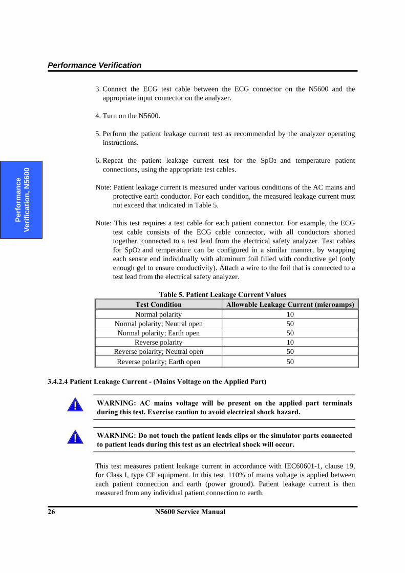
3. Connect the ECG test cable between the ECG connector on the N5600 and the appropriate input connector on the analyzer.
4. Turn on the N5600. 5. Perform the patient leakage current test as recommended by the analyzer operating
instructions. 6. Repeat the patient leakage current test for the SpO2 and temperature patient
connections, using the appropriate test cables. Note: Patient leakage current is measured under various conditions of the AC mains and
protective earth conductor. For each condition, the measured leakage current must not exceed that indicated in Table 5.
Note: This test requires a test cable for each patient connector. For example, the ECG
test cable consists of the ECG cable connector, with all conductors shorted together, connected to a test lead from the electrical safety analyzer. Test cables for SpO2 and temperature can be configured in a similar manner, by wrapping each sensor end individually with aluminum foil filled with conductive gel (only enough gel to ensure conductivity). Attach a wire to the foil that is connected to a test lead from the electrical safety analyzer.
Table 5. Patient Leakage Current Values
Test Condition Allowable Leakage Current (microamps)Normal polarity 10
Normal polarity; Neutral open 50 Normal polarity; Earth open 50
Reverse polarity 10 Reverse polarity; Neutral open 50 Reverse polarity; Earth open 50
3.4.2.4 Patient Leakage Current - (Mains Voltage on the Applied Part)
WARNING: AC mains voltage will be present on the applied part terminals during this test. Exercise caution to avoid electrical shock hazard.
WARNING: Do not touch the patient leads clips or the simulator parts connected to patient leads during this test as an electrical shock will occur.
This test measures patient leakage current in accordance with IEC60601-1, clause 19, for Class I, type CF equipment. In this test, 110% of mains voltage is applied between each patient connection and earth (power ground). Patient leakage current is then measured from any individual patient connection to earth.
Performance Verification
N5600 Service Manual 27
Perform
ance Verification, N
5600
Note: Keep the patient test cable length as short as possible during the leakage test. Note: This test requires the same test cables for each patient connector as described in
3.4.2.3 Patient Leakage Current. 1. Configure electrical safety analyzer as recommended by analyzer operating
instructions. 2. Connect monitor’s AC mains power cord to analyzer as recommended by analyzer
operating instructions. 3. Connect ECG test cable between ECG connector on N5600 and appropriate input
connector on analyzer. 4. Turn on N5600. 5. Perform test as recommended by analyzer operating instructions. 6. Repeat test for SpO2 and temperature patient connections, using appropriate test
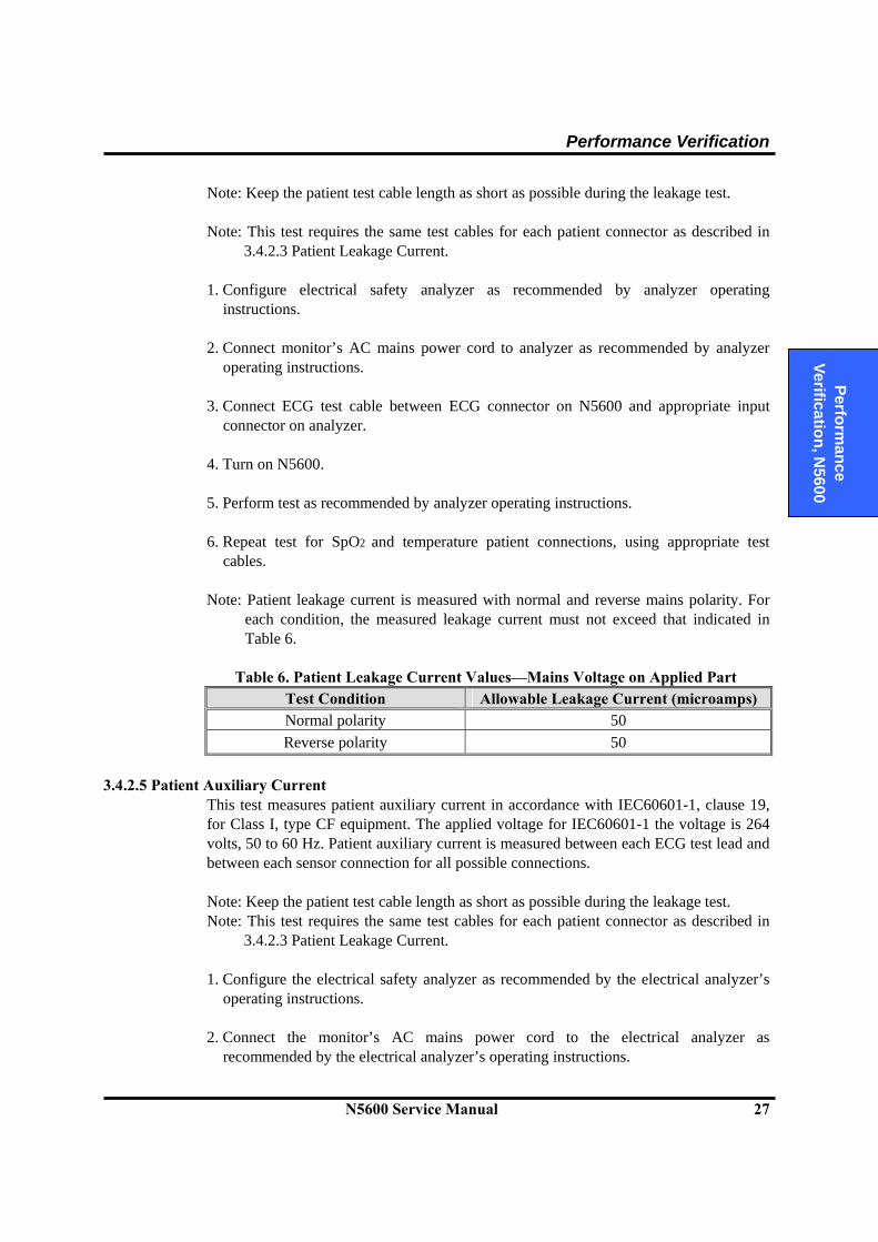
cables. Note: Patient leakage current is measured with normal and reverse mains polarity. For
each condition, the measured leakage current must not exceed that indicated in Table 6.
Table 6. Patient Leakage Current Values—Mains Voltage on Applied Part
Test Condition Allowable Leakage Current (microamps) Normal polarity 50 Reverse polarity 50
3.4.2.5 Patient Auxiliary Current
This test measures patient auxiliary current in accordance with IEC60601-1, clause 19, for Class I, type CF equipment. The applied voltage for IEC60601-1 the voltage is 264 volts, 50 to 60 Hz. Patient auxiliary current is measured between each ECG test lead and between each sensor connection for all possible connections. Note: Keep the patient test cable length as short as possible during the leakage test. Note: This test requires the same test cables for each patient connector as described in
3.4.2.3 Patient Leakage Current. 1. Configure the electrical safety analyzer as recommended by the electrical analyzer’s
operating instructions. 2. Connect the monitor’s AC mains power cord to the electrical analyzer as
recommended by the electrical analyzer’s operating instructions.
Performance Verification
28 N5600 Service Manual
Pe
rfor
man
ce
Verif
icat
ion,
N56
00
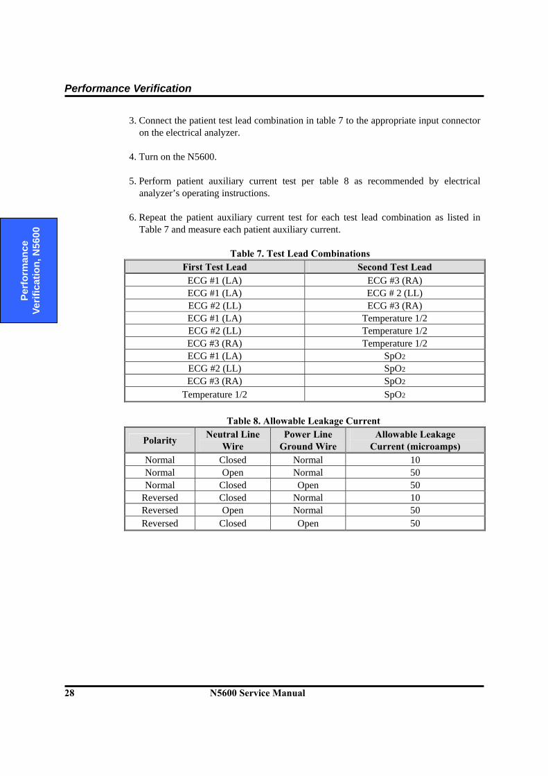
3. Connect the patient test lead combination in table 7 to the appropriate input connector on the electrical analyzer.
4. Turn on the N5600.
5. Perform patient auxiliary current test per table 8 as recommended by electrical
analyzer’s operating instructions. 6. Repeat the patient auxiliary current test for each test lead combination as listed in
Table 7 and measure each patient auxiliary current.
Table 7. Test Lead Combinations First Test Lead Second Test Lead
ECG #1 (LA) ECG #3 (RA) ECG #1 (LA) ECG # 2 (LL) ECG #2 (LL) ECG #3 (RA) ECG #1 (LA) Temperature 1/2 ECG #2 (LL) Temperature 1/2 ECG #3 (RA) Temperature 1/2 ECG #1 (LA) SpO2 ECG #2 (LL) SpO2 ECG #3 (RA) SpO2
Temperature 1/2 SpO2
Table 8. Allowable Leakage Current
Polarity Neutral Line Wire
Power Line Ground Wire
Allowable Leakage Current (microamps)
Normal Closed Normal 10 Normal Open Normal 50 Normal Closed Open 50
Reversed Closed Normal 10 Reversed Open Normal 50 Reversed Closed Open 50
Section 4: Service menu and Factory Default Settings
4.1 Introduction 4.2 Service Menu 4.3 Demo Mode 4.4 Factory Default Settings
N5600 Service Manual 29
D
efault Settings and Troubleshooting
4.1 Introduction
This section discusses use of the Service menu to configure Power-on default settings, Alarm Suspend, Alarm Silence Period, Audible Alarm Type, AC Line Frequency, Language selections, NIBP Test Mode access, and System Information to obtain service-related information about the monitor. Also this section explains briefly the factory default settings and Demo mode.
4.2 Service Menu
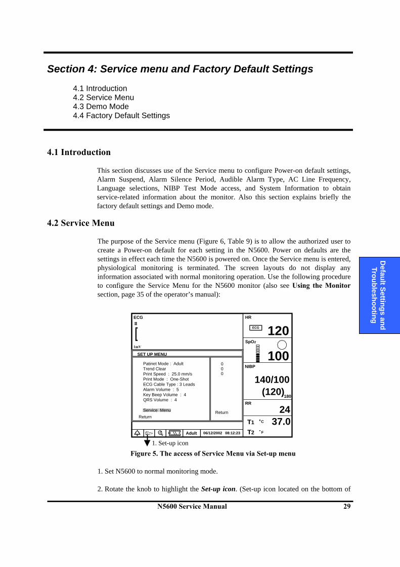
The purpose of the Service menu (Figure 6, Table 9) is to allow the authorized user to create a Power-on default for each setting in the N5600. Power on defaults are the settings in effect each time the N5600 is powered on. Once the Service menu is entered, physiological monitoring is terminated. The screen layouts do not display any information associated with normal monitoring operation. Use the following procedure to configure the Service Menu for the N5600 monitor (also see Using the Monitor section, page 35 of the operator’s manual):
Figure 5. The access of Service Menu via Set-up menu
1. Set N5600 to normal monitoring mode. 2. Rotate the knob to highlight the Set-up icon. (Set-up icon located on the bottom of
SET UP MENU
Return
06/12/2002 08:12:23Adult
120
100
140/100(120)
RR
T1
T2
24
SpO21mV
ECG
HR
37.0
180
ECG
NIBP
C
F
Patinet Mode : AdultTrend ClearPrint Speed : 25.0 mm/sPrint Mode : One-ShotECG Cable Type : 3 LeadsAlarm Volume : 5Key Beep Volume : 4QRS Volume : 4
Service Menu Return
000
1. Set-up icon
Service Menu and Factory Default Settings
30 N5600 Service Manual
D
efau
lt Se
tting
s an
d Tr
oubl
esho
otin
g
the screen display). Press the knob. Set-up menu displays. 3. Rotate the knob to highlight Service Menu in the Set-up menu, and then press the
knob to access the Service Menu.
4. Three digits displays in the Level 2 Menu as shown in Figure 5. Note: The access code is 4, 0, 2. It is set at the factory and may not be changed.
5. Rotate the knob to highlight the top of the digits. Press the knob to enter the access
code. The digit turns yellow. This indicates that it is ready to rotate the knob in order to change the digit.
6. Rotate the knob until “4” appears, then press the knob. 7. Repeat step 5-6 to enter all the access code “4” “0” “2”.
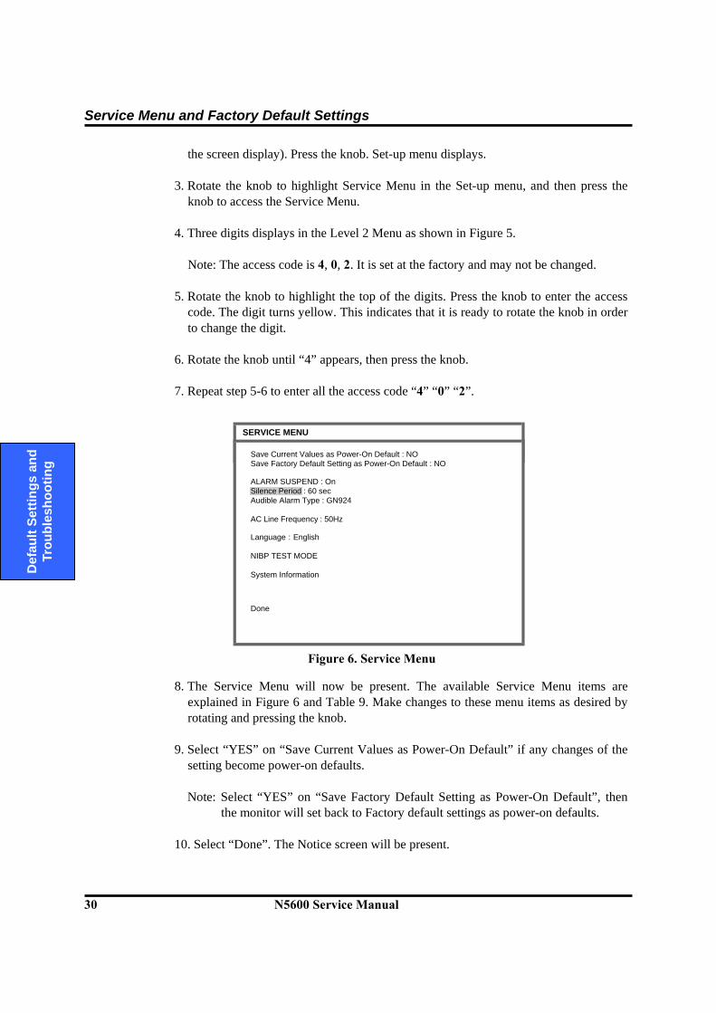
Figure 6. Service Menu 8. The Service Menu will now be present. The available Service Menu items are
explained in Figure 6 and Table 9. Make changes to these menu items as desired by rotating and pressing the knob.
9. Select “YES” on “Save Current Values as Power-On Default” if any changes of the
setting become power-on defaults.
Note: Select “YES” on “Save Factory Default Setting as Power-On Default”, then the monitor will set back to Factory default settings as power-on defaults.
10. Select “Done”. The Notice screen will be present.
SERVICE MENU
Done
Save Current Values as Power-On Default : NOSave Factory Default Setting as Power-On Default : NO
ALARM SUSPEND : OnSilence Period : 60 secAudible Alarm Type : GN924
AC Line Frequency : 50Hz
Language : English
NIBP TEST MODE
System Information
Service Menu and Factory Default Settings
N5600 Service Manual 31
D
efault Settings and Troubleshooting
11. Turn the monitor off, then power the monitor on again.
Note: The monitor must be powered off upon selecting “Done” to save any changes into the monitor, and then the changes made to the Power on defaults will be in effect next time the unit is powered up.
Note: If you do not select “YES” on save current values or back to factory defaults as
power-on default, the monitor will not save any changes and it will be automatically powered off upon selecting “Done” to exit Service menu screen.
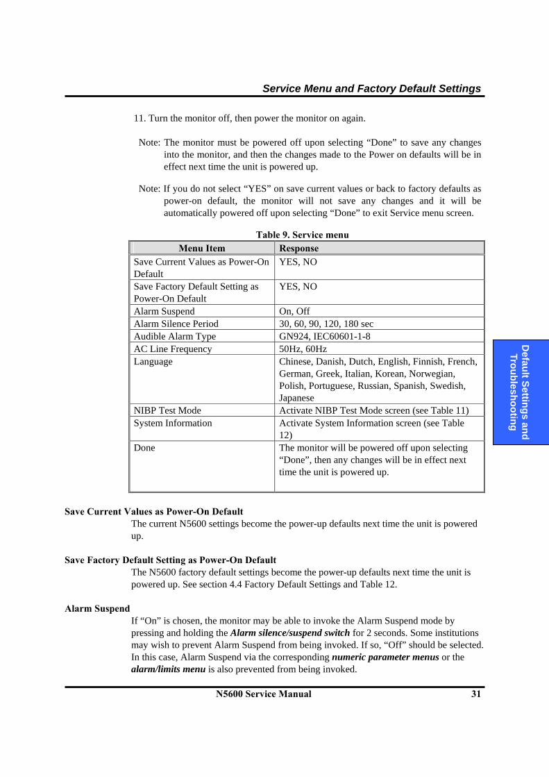
Table 9. Service menu
Menu Item Response Save Current Values as Power-On Default
YES, NO
Save Factory Default Setting as Power-On Default
YES, NO
Alarm Suspend On, Off Alarm Silence Period 30, 60, 90, 120, 180 sec Audible Alarm Type GN924, IEC60601-1-8 AC Line Frequency 50Hz, 60Hz Language Chinese, Danish, Dutch, English, Finnish, French,
German, Greek, Italian, Korean, Norwegian, Polish, Portuguese, Russian, Spanish, Swedish, Japanese
NIBP Test Mode Activate NIBP Test Mode screen (see Table 11) System Information Activate System Information screen (see Table
12) Done The monitor will be powered off upon selecting
“Done”, then any changes will be in effect next time the unit is powered up.
Save Current Values as Power-On Default
The current N5600 settings become the power-up defaults next time the unit is powered up.
Save Factory Default Setting as Power-On Default The N5600 factory default settings become the power-up defaults next time the unit is powered up. See section 4.4 Factory Default Settings and Table 12.
Alarm Suspend If “On” is chosen, the monitor may be able to invoke the Alarm Suspend mode by pressing and holding the Alarm silence/suspend switch for 2 seconds. Some institutions may wish to prevent Alarm Suspend from being invoked. If so, “Off” should be selected. In this case, Alarm Suspend via the corresponding numeric parameter menus or the alarm/limits menu is also prevented from being invoked.
Service Menu and Factory Default Settings
32 N5600 Service Manual
D
efau
lt Se
tting
s an
d Tr
oubl
esho
otin
g
Alarm Silence Period Pressing the Alarm silence/suspend switch temporarily silences alarms for the time indicated in the Silence Period.
Audible Alarm Type GN924 or IEC60601-1-8 The N5600 has two different audible alarm types, called GN924 and IEC60601-1-8. They have different tone pitch and on-off beep patterns. (Refer to Alarms and Limits section in the operator’s manual)
AC Line Frequency 50 Hz or 60Hz The monitor is designed for supporting AC line frequency both 50 Hz and 60 Hz. Select either 50Hz or 60 Hz frequency for an appropriate AC line.
Language The language selected will be used for all the text shown on the display; the selected language will be effective the next time the monitor is powered up. Note: If an unfamiliar language is chosen, the user may find it difficult to operate the
monitor. NIBP Test Mode
WARNING: A blood pressure cuff, connected to the monitor, should never be applied to a human subject while the monitor is in NIBP Test Mode, as injury could result. NIBP Test Mode provides to facilitate performing verification testing for the NIBP subsystem. Typically, when these tests are performed, the pneumatic system is connected to an NIBP simulator or a Rigid cuff can as a closed reference volume. For the detailed test procedures in this mode, refer to the Performance Test section. The NIBP Tests are described in Table 10. When any of NIBP tests is initiated, “Test in Progress” message will appears on the right of the top screen during the test. In the NIBP Test Mode, no function switch will have no effect except the knob. All the tests will start to be performed by pressing or rotating the knob. If you would like to stop the test during test progressing, press the knob. Note: If any further NIBP test is not selected to be performed after a test is completed, a
notice screen will display in approximately 10 minutes.
Service Menu and Factory Default Settings
N5600 Service Manual 33
D
efault Settings and Troubleshooting
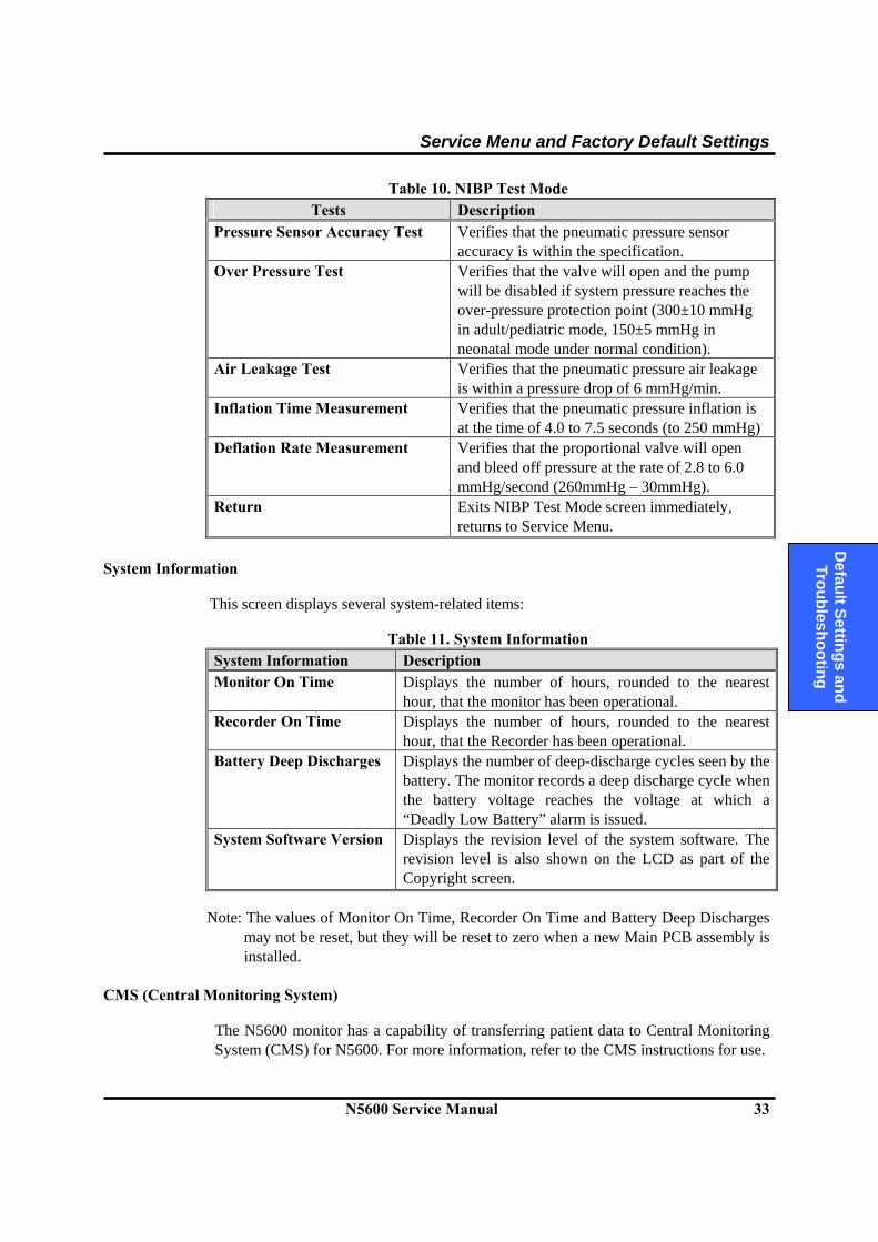
Table 10. NIBP Test Mode Tests Description
Pressure Sensor Accuracy Test Verifies that the pneumatic pressure sensor accuracy is within the specification.
Over Pressure Test Verifies that the valve will open and the pump will be disabled if system pressure reaches the over-pressure protection point (300±10 mmHg in adult/pediatric mode, 150±5 mmHg in neonatal mode under normal condition).
Air Leakage Test Verifies that the pneumatic pressure air leakage is within a pressure drop of 6 mmHg/min.
Inflation Time Measurement Verifies that the pneumatic pressure inflation is at the time of 4.0 to 7.5 seconds (to 250 mmHg)
Deflation Rate Measurement Verifies that the proportional valve will open and bleed off pressure at the rate of 2.8 to 6.0 mmHg/second (260mmHg – 30mmHg).
Return Exits NIBP Test Mode screen immediately, returns to Service Menu.
System Information
This screen displays several system-related items:
Table 11. System Information System Information Description Monitor On Time Displays the number of hours, rounded to the nearest
hour, that the monitor has been operational. Recorder On Time Displays the number of hours, rounded to the nearest
hour, that the Recorder has been operational. Battery Deep Discharges Displays the number of deep-discharge cycles seen by the
battery. The monitor records a deep discharge cycle when the battery voltage reaches the voltage at which a “Deadly Low Battery” alarm is issued.
System Software Version Displays the revision level of the system software. The revision level is also shown on the LCD as part of the Copyright screen.
Note: The values of Monitor On Time, Recorder On Time and Battery Deep Discharges
may not be reset, but they will be reset to zero when a new Main PCB assembly is installed.
CMS (Central Monitoring System)
The N5600 monitor has a capability of transferring patient data to Central Monitoring System (CMS) for N5600. For more information, refer to the CMS instructions for use.
Service Menu and Factory Default Settings
34 N5600 Service Manual
D
efau
lt Se
tting
s an
d Tr
oubl
esho
otin
g
4.3 Demo Mode The purpose of Demo mode is to show a visual presentation demonstrating how the N5600 monitor works. The following procedure is set to Demo mode. 1.Turn the N5600 monitor on. 2.Rotate the knob to highlight the Set-up icon, then press the knob. Set-up menu
displays. 3.Rotate the knob to highlight Service Menu in the Set-up menu (see Figure 5), and
then press the knob to enter the Demo access code for Demo mode. 4.Three digits displays in the Level 2 Menu as shown in Figure 5. 5.Rotate the knob to highlight the top of the digits. Press the knob to enter the Demo
access code, “3” “1” “4” in this order. 6.The monitor is now set to Demo mode, and demonstrates a typical monitoring screen.
4.4 Factory Default Settings
Factory default settings are divided into three groups, adult, pediatric and neonatal as described in Table 12. The parameters of the N5600 monitor are preset to “Adult” monitoring mode. Alarm limits settings will be automatically changed to the default settings for each patient mode as the mode is changed to Adult, Pediatric or Neonatal mode.
Table 12. Factory Default Settings for the N5600 Factory Defaults Parameter Adult Pediatric Neonatal
Monitoring Mode Adult Pediatric Neonatal NIBP Initial Cuff Inflation 180 mmHg 180 mmHg 120 mmHg NIBP Auto Mode Interval OFF OFF OFF NIBP SYS Alarm Upper Limits 160 mmHg 120 mmHg 90 mmHg NIBP SYS Alarm Lower Limits 90 mmHg 70 mmHg 40 mmHg NIBP DIA Alarm Upper Limits 90 mmHg 70 mmHg 60 mmHg NIBP DIA Alarm Lower Limits 50 mmHg 40 mmHg 20 mmHg NIBP MAP Alarm Upper Limits 110 mmHg 90 mmHg 70 mmHg NIBP MAP Alarm Lower Limits 60 mmHg 50 mmHg 30 mmHg ECG Size AUTO AUTO AUTO ECG Filter Mode Monitor Monitor Monitor ECG Pacer Detect OFF OFF OFF ECG Sweep Speed 25.0 mm/s 25.0 mm/s 25.0 mm/s

Service Menu and Factory Default Settings
N5600 Service Manual 35
D
efault Settings and Troubleshooting
Factory Defaults Parameter Adult Pediatric Neonatal
Heart Rate Tone Source ECG ECG ECG Heart Rate Alarm Upper Limits 120 BPM 160 BPM 200 BPM Heart Rate Alarm Lower Limits 50 BPM 75 BPM 100 BPM C-Lock OFF OFF OFF Satseconds Value OFF OFF OFF SpO2 In-Sensor Type %SpO2 %SpO2 %SpO2 SpO2 Sweep Speed 25.0 mm/s 25.0 mm/s 25.0 mm/s %SpO2 Alarm Upper Limits 100 % 100 % 95 % %SpO2 Alarm Lower Limits 90 % 90 % 80 % Respiration On/Off ON ON ON Respiration Size Size Level 3 Size Level 3 Size Level 3 Respiration Sweep Speed 12.5 mm/s 12.5 mm/s 12.5 mm/s RR Alarm Upper Limits 30 BPM 30 BPM 100 BPM RR Alarm Lower Limits 8 BPM 8 BPM 30 BPM Temperature Unit T1 º C º C º C Temperature Unit T2 º C º C º C T1 Alarm Upper Limits 39.0 ºC (102.2 ºF) 39.0 ºC (102.2 ºF) 39.0 ºC (102.2 ºF)T1 Alarm Lower Limits 36.0 ºC (96.8 ºF) 36.0 ºC (96.8 ºF) 36.0 ºC (96.8 ºF) T2 Alarm Upper Limits 39.0 ºC (102.2 ºF) 39.0 ºC (102.2 ºF) 39.0 ºC (102.2 ºF)T2 Alarm Lower Limits 36.0 ºC (96.8 ºF) 36.0 ºC (96.8 ºF) 36.0 ºC (96.8 ºF) Print-On-Alarm OFF OFF OFF Alarm Suspend Initiation OFF OFF OFF Alarm Suspend Access ON ON ON Alarm Silence Period 60 seconds 60 seconds 60 seconds Audible Alarm Type GN 924 GN 924 GN 924 ECG Cable Type 3 leads 3 leads 3 leads Alarm Volume 5 5 5 Key Beep Volume 4 4 4 QRS Volume 4 4 4 Tabular Trend Time Interval 20 seconds 20 seconds 20 seconds AC Line Frequency 50 Hz 50 Hz 50 Hz Print mode** One-Shot One-Shot One-Shot Print Speed** 25.0 mm/s 25.0 mm/s 25.0 mm/s Language English English English
Note: Asterisks (**) by a parameter in the above table indicate the print settings in
which an optional thermal printer installed. Note: The factory default value of “AC Line Frequency” is preset to 60 Hz for the
N5600 software version 1.00, 1.01, 1.02 and 1.03 only. Check your N5600 monitor for the software version installed.
Service Menu and Factory Default Settings
36 N5600 Service Manual
D
efau
lt Se
tting
s an
d Tr
oubl
esho
otin
g
This page is intentionally left blank.
Section 5: Troubleshooting
5.1 Introduction 5.2 How to Use This Section 5.3 Who Should Perform Repairs 5.4 Replacement Level Supported 5.5 Troubleshooting Guide
N5600 Service Manual 37
D
efault Settings and Troubleshooting
5.1 Introduction
This section explains how to troubleshoot the N5600 if problems arise. Tables are supplied that list possible monitor difficulties, along with probable causes, and recommended actions to correct the difficulty.
5.2 How to Use This Section
Use this section in conjunction with Performance Verification section and Spare Parts section. To remove and replace a part you suspect is defective, follow the instructions in Disassembly Guide section.
5.3 Who Should Perform Repairs
Only qualified service personnel should open the monitor housing, remove and replace components, or make adjustments in accordance with this service manual. If your medical facility does not have qualified service personnel, contact Tyco Healthcare Technical Services or your local Tyco Healthcare representative.
5.4 Replacement Level Supported The replacement level supported for this product is to the printed circuit board (PCB assembly) and major subassembly level. Once you isolate a suspected PCB assembly, follow the procedures in Disassembly Guide section, to replace the PCB assembly with a known good PCB assembly. Check to see if the trouble symptom disappears and that the monitor passes all performance tests. If the trouble symptom persists, swap back the replacement PCB assembly with the suspected malfunctioning PCB assembly (the original PCB assembly that was installed when you started troubleshooting) and continue troubleshooting as directed in this section. Obtaining Replacement Parts Tyco Healthcare Technical Services provides technical assistance information and replacement parts. To obtain replacement parts, contact Tyco Healthcare or your local Tyco Healthcare representative. Refer to parts by the part names and part numbers listed in Spare Parts section.

Troubleshooting
38 N5600 Service Manual
D
efau
lt Se
tting
s an
d Tr
oubl
esho
otin
g
5.5 Troubleshooting Guide Problems with the N5600 are separated into the categories in Table 13. Refer to the paragraph indicated for further troubleshooting instructions in this section. Note: Taking the recommended actions discussed in this section will correct the
majority of problems you will encounter. However, problems not covered here can be resolved by calling Tyco Healthcare Technical Services or your local Tyco Healthcare representative.
All of the categories in Table 13 are discussed in the following paragraphs.
Table 13. Problem Categories Problem Area Refer to Paragraph
1. Power No power-up Fails power-on self-test Powers down without apparent cause
5.5.1 Power
2. Display Display does not respond properly
5.5.2 Display
3. Switches/Knob Monitor does not respond properly to switches
5.5.3 Switches/Knobs
4. Alarms/Audible Tones Alarms are generated without apparent cause Tones do not sound properly
5.5.4 Alarms/Audible Tones
5. Operational Performance Displays appear to be operational, but monitor
shows no readings Suspect readings Printer not responding
5.5.5 Operational Performance
6. Error Codes Error code displays on the screen
5.5.6 Error Codes
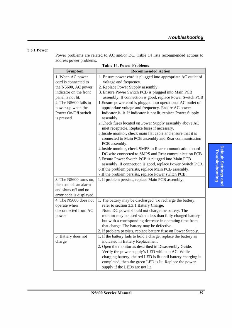
Troubleshooting
N5600 Service Manual 39
D
efault Settings and Troubleshooting
5.5.1 Power Power problems are related to AC and/or DC. Table 14 lists recommended actions to address power problems.
Table 14. Power Problems Symptom Recommended Action
1. When AC power cord is connected to the N5600, AC power indicator on the front panel is not lit.
1. Ensure power cord is plugged into appropriate AC outlet of voltage and frequency.
2. Replace Power Supply assembly. 3. Ensure Power Switch PCB is plugged into Main PCB
assembly. If connection is good, replace Power Switch PCB2. The N5600 fails to power-up when the Power On/Off switch is pressed.
1.Ensure power cord is plugged into operational AC outlet of appropriate voltage and frequency. Ensure AC power indicator is lit. If indicator is not lit, replace Power Supply assembly.
2.Check fuses located on Power Supply assembly above AC inlet receptacle. Replace fuses if necessary.
3.Inside monitor, check main flat cable and ensure that it is connected to Main PCB assembly and Rear communication PCB assembly.
4.Inside monitor, check SMPS to Rear communication board DC wire connected to SMPS and Rear communication PCB.
5.Ensure Power Switch PCB is plugged into Main PCB assembly. If connection is good, replace Power Switch PCB.
6.If the problem persists, replace Main PCB assembly. 7.If the problem persists, replace Power switch PCB.
3. The N5600 turns on, then sounds an alarm and shuts off and no error code is displayed.
1. If problem persists, replace Main PCB assembly.
4. The N5600 does not operate when disconnected from AC power
1. The battery may be discharged. To recharge the battery, refer to section 3.3.1 Battery Charge. Note: DC power should not charge the battery. The monitor may be used with a less than fully charged battery but with a corresponding decrease in operating time from that charge. The battery may be defective.
2. If problem persists, replace battery fuse on Power Supply. 5. Battery does not charge
1. If the battery fails to hold a charge, replace the battery as indicated in Battery Replacement
2. Open the monitor as described in Disassembly Guide. Verify the power supply’s LED while on AC. While charging battery, the red LED is lit until battery charging is completed, then the green LED is lit. Replace the power supply if the LEDs are not lit.
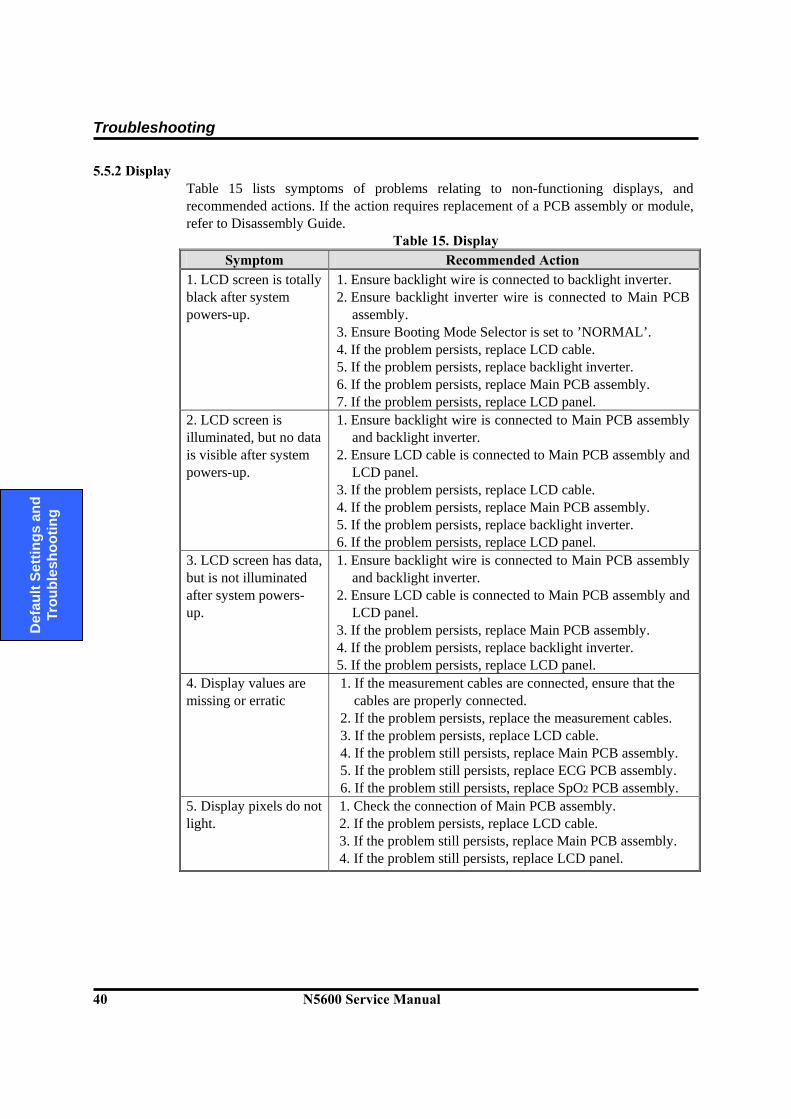
Troubleshooting
40 N5600 Service Manual
D
efau
lt Se
tting
s an
d Tr
oubl
esho
otin
g
5.5.2 Display Table 15 lists symptoms of problems relating to non-functioning displays, and recommended actions. If the action requires replacement of a PCB assembly or module, refer to Disassembly Guide.
Table 15. Display Symptom Recommended Action
1. LCD screen is totally black after system powers-up.
1. Ensure backlight wire is connected to backlight inverter. 2. Ensure backlight inverter wire is connected to Main PCB
assembly. 3. Ensure Booting Mode Selector is set to ’NORMAL’. 4. If the problem persists, replace LCD cable. 5. If the problem persists, replace backlight inverter. 6. If the problem persists, replace Main PCB assembly. 7. If the problem persists, replace LCD panel.
2. LCD screen is illuminated, but no data is visible after system powers-up.
1. Ensure backlight wire is connected to Main PCB assembly and backlight inverter.
2. Ensure LCD cable is connected to Main PCB assembly and LCD panel.
3. If the problem persists, replace LCD cable. 4. If the problem persists, replace Main PCB assembly. 5. If the problem persists, replace backlight inverter. 6. If the problem persists, replace LCD panel.
3. LCD screen has data, but is not illuminated after system powers-up.
1. Ensure backlight wire is connected to Main PCB assembly and backlight inverter.
2. Ensure LCD cable is connected to Main PCB assembly and LCD panel.
3. If the problem persists, replace Main PCB assembly. 4. If the problem persists, replace backlight inverter. 5. If the problem persists, replace LCD panel.
4. Display values are missing or erratic
1. If the measurement cables are connected, ensure that the cables are properly connected.
2. If the problem persists, replace the measurement cables. 3. If the problem persists, replace LCD cable. 4. If the problem still persists, replace Main PCB assembly. 5. If the problem still persists, replace ECG PCB assembly. 6. If the problem still persists, replace SpO2 PCB assembly.
5. Display pixels do not light.
1. Check the connection of Main PCB assembly. 2. If the problem persists, replace LCD cable. 3. If the problem still persists, replace Main PCB assembly. 4. If the problem still persists, replace LCD panel.

Troubleshooting
N5600 Service Manual 41
D
efault Settings and Troubleshooting
5.5.3 Switches/Knobs Table 16 lists symptoms of problems and recommended actions to address problems with the knob and front panel switches.
Table 16. Switches/Knob Problems Symptom Recommended Action
1. N5600 fails to power-up when Power On/Off switch is pressed.
1. Take steps as noted in paragraph 5.5.1.
2. N5600 powers-up, but some or one of the other switches respond.
1. Ensure Function switch PCB is plugged into Main PCB assembly. If connection is good, change Function switch PCB.
2. If problem persists, change Main PCB assembly. 3. When knob is rotated, no highlight appears on display screen, and/or monitor does not respond to knob presses.
1. Ensure encoder wire is plugged into Main PCB assembly. If connection is good, change encoder.
2. If problem persists, replace Main PCB assembly.
5.5.4 Alarms/Audible Tones
Table 17 lists symptoms of problems and recommended actions to address problems with the display and audible tones.
Table 17. Alarms/Audible Tones Problems Symptom Recommended Action
1. Alarm sounds for no apparent reason
1. Moisture or spilt liquids can cause an alarm not to sound. Allow the monitor to dry thoroughly before using
2. If the problem persists, replace Main PCB assembly. 2. Audible alarm does not sound.
1. Check alarm silence status. 2. Verify alarm volume setting in Set-up menu. 3. Check 50 pi speaker connection. Ensure 50 pi speaker wire
is connected to rear communication PCB. 4. If problem persists, replace 50 pi speaker assembly. 5. Check the flat cable between main PCB and rear
communication PCB. 6. If problem persists, replace Main PCB assembly. 7. If problem persists, replace rear communication PCB.
3. N5600 responds to switch press, but key press tone fails to sound.
1. Check Key Beep volume setting in Set-up menu. 2. Ensure 30 pi speaker wire is connected to rear
communication PCB. 3. If problem persists, replace 30 pi speaker assembly. 4. Check the flat cable between Main PCB and rear
communication PCB. 5. If problem persists, replace Main PCB assembly. 6. If problem persists, replace rear communication PCB.

Troubleshooting
42 N5600 Service Manual
D
efau
lt Se
tting
s an
d Tr
oubl
esho
otin
g
5.5.5 Operational Performance Table 18 lists symptoms of problems relating to operational performance (no error codes displayed) and recommended actions. If the action requires replacement of a PCB or module, refer to Disassembly Guide.
Table 18. Operational Performance Problems Symptom Recommended Action
1. Monitor appears to be operational, but physiological values are suspect or nonexistent.
1. Replace each patient cable (or hose) with a known serviceable cable.
2. Ensure internal ECG, temperature, and SpO2 cables are connected to main PCB assembly. Ensure hoses in pneumatic system are properly connected, and NIBP pump motor is connected to power supply PCB assembly.
3. If problem persists, replace main PCB assembly. 2. Monitor appears to be operational, but the date & time display section is blank.
1. Disassemble the Main PCB, then check the connection of 32.768kHz cylinder type oscillator (PCB Reference : X1) on Main PCB. If necessary, re-solder the leads of oscillator.
2. If the problem persists, replace Main PCB assembly.
3. Printer paper will not advance. 1. Open printer door and check paper is present. 2. If problem persists, ensure printer wire is
connected to SpO2 PCB assembly. 3. If problem persists, replace printer.
4. Printer paper will advance, but paper remains blank when printing should be present.
1. Open printer door and check paper is oriented correctly.
2. If problem persists, replace printer.
5.5.6 Error Codes
When the N5600 detects an error condition, the monitor will attempt to show an error code on the display screen. If such an error occurs during monitoring operation, the monitor will sound a low-priority alarm. Audible alarm can be terminated by pressing Alarm silence/suspend switch, but it depends on error codes and conditions. Table 19 provides a complete list of error codes and problem identification. If an error code occurs, take the following actions:
1. Turn monitor off, then on again.
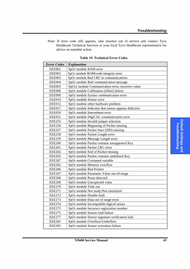
Troubleshooting
N5600 Service Manual 43
D
efault Settings and Troubleshooting
Note: If error code still appears, take monitor out of service and contact Tyco Healthcare Technical Services or your local Tyco Healthcare representative for advice on remedial action.
Table 19. Technical Error Codes
Error Codes Explanation
EEE001 SpO2 module RAM error EEE002 SpO2 module ROM/code integrity error EEE003 SpO2 module Bad CRC in communications EEE004 SpO2 module Bad communication message EEE005 SpO22 module Communication error, incorrect value EEE006 SpO2 module Calibration (offset) failure EEE009 SpO2 module Syntax communication error EEE010 SpO2 module Sensor error EEE012 SpO2 module other hardware problem EEE017 SpO2 module Indicator that sensor appears defective EEE050 SpO2 module Intermittent error EEE051 SpO2 module DigiCAL communication error EEE255 SpO2 module Invalid jumper selection EEE256 SpO2 module Beginning of Packet missing EEE257 SpO2 module Packet Start (SID) missing EEE258 SpO2 module Packet Length error EEE259 SpO2 module Message Length error EEE260 SpO2 module Packet contains unsupported Key EEE261 SpO2 module Packet CRC error EEE262 SpO2 module End of Packet missing EEE263 SpO2 module Packet contains undefined Key EEE267 SpO2 module Corrupted variable EEE265 SpO2 module Memory overflow EEE266 SpO2 module Bad Pointer EEE267 SpO2 module Parameter Value out-of-range EEE268 SpO2 module Reset detected EEE269 SpO2 module Unexpected value EEE270 SpO2 module Time out EEE271 SpO2 module Not ready/Not initialized EEE272 SpO2 module Double fault EEE273 SpO2 module Data out of range error EEE274 SpO2 module Incompatible digical sensor EEE275 SpO2 module Incorrect registration number EEE275 SpO2 module Sensor read failure EEE277 SpO2 module Sensor signature verification fails EEE281 SpO2 module Overflow/Underflow EEE282 SpO2 module Sensor activation failure
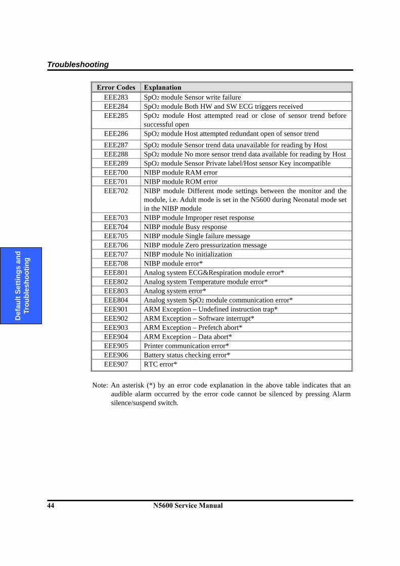
Troubleshooting
44 N5600 Service Manual
D
efau
lt Se
tting
s an
d Tr
oubl
esho
otin
g
Error Codes Explanation EEE283 SpO2 module Sensor write failure EEE284 SpO2 module Both HW and SW ECG triggers received EEE285 SpO2 module Host attempted read or close of sensor trend before
successful open EEE286 SpO2 module Host attempted redundant open of sensor trend EEE287 SpO2 module Sensor trend data unavailable for reading by Host EEE288 SpO2 module No more sensor trend data available for reading by HostEEE289 SpO2 module Sensor Private label/Host sensor Key incompatible EEE700 NIBP module RAM error EEE701 NIBP module ROM error EEE702 NIBP module Different mode settings between the monitor and the
module, i.e. Adult mode is set in the N5600 during Neonatal mode set in the NIBP module
EEE703 NIBP module Improper reset response EEE704 NIBP module Busy response EEE705 NIBP module Single failure message EEE706 NIBP module Zero pressurization message EEE707 NIBP module No initialization EEE708 NIBP module error* EEE801 Analog system ECG&Respiration module error* EEE802 Analog system Temperature module error* EEE803 Analog system error* EEE804 Analog system SpO2 module communication error* EEE901 ARM Exception – Undefined instruction trap* EEE902 ARM Exception – Software interrupt* EEE903 ARM Exception – Prefetch abort* EEE904 ARM Exception – Data abort* EEE905 Printer communication error* EEE906 Battery status checking error* EEE907 RTC error*
Note: An asterisk (*) by an error code explanation in the above table indicates that an
audible alarm occurred by the error code cannot be silenced by pressing Alarm silence/suspend switch.
Section 6: Disassembly Guide
6.1 General 6.2 Replacement Level Supported 6.3 Prior to Disassembly 6.4 Fuse Replacement 6.5 Battery Disassembly 6.6 Monitor Disassembly 6.7 Front Case Disassembly Procedures 6.8 Rear Case Disassembly Procedures 6.9 Optional Printer Assembly/Disassembly Procedures
N5600 Service Manual 45
D
isassembly G
uide/ Spare Parts, N
5600
WARNING: Performance Verification. Do not place the N5600 into operation after repair or maintenance has been performed, until all Performance Tests and Safety Tests listed in Section 3 of this service manual have been performed. Failure to perform all tests could result in erroneous monitor readings.
WARNING: Before attempting to open or disassemble the N5600, disconnect the power cord from the N5600. CAUTION: Observe ESD (electrostatic discharge) precautions when working within the unit. Note: Some spare parts have a business reply card attached. When you receive these
spare parts, please fill out and return the card.
6.1 General This section describes disassembly procedures detailed disassembly instructions and accompanied by illustrations. Disassembly Sequence Flow Chart that is used to access replaceable parts of the N5600 is illustrated in Figure 7. The boxes on the flow chart represent the various components or sub-assemblies. A complete listing of the available spare parts and part numbers is in Spare Parts section. Follow the reverse sequence of the disassembly procedures for reassembly. The N5600 can be disassembled down to all major component parts, including:
PCB assemblies acquisition modules, SMPS & LCD battery cables brackets & cases printer
The following tools are required:
small, Phillips-head (+) screwdriver medium, Phillips-head (+) screwdriver needle-nose pliers
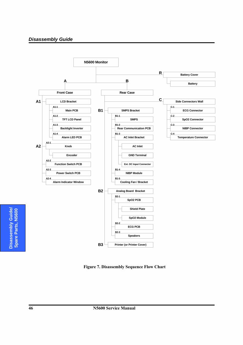
Disassembly Guide
46 N5600 Service Manual
D
isas
sem
bly
Gui
de/
Spar
e Pa
rts, N
5600
N5600 Monitor
Front Case
LCD Bracket
Rear Case
SMPS Bracket
Analog Board Bracket
AC Inlet Bracket
SpO2 PCB
SpO2 Module
Speakers
AC Inlet
GND Terminal
Ext. DC Input Connector
Side Connectors Wall
Printer (or Printer Cover)
Main PCB
Backlight Inverter
Alarm LED PCB
TFT LCD Panel
Function Switch PCB
Power Switch PCB
Encoder
Knob
Alarm Indicator Window
SMPS
Rear Communication PCB
NIBP Module
Cooling Fan / Bracket
A B
ECG Connector
SpO2 Connector
NIBP Connector
Temperature Connector
Shield Plate
A1
A2
ECG PCB
B1
B2
B3
A1-1
A1-2
A1-3
A1-4
A2-1
A2-2
A2-3
A2-4
B1-1
B1-2
B1-3
B1-4
B1-5
B2-1
B2-2
B2-3
C-3
C-1
C-2
C-4
Battery Cover
Battery
R
C
Figure 7. Disassembly Sequence Flow Chart
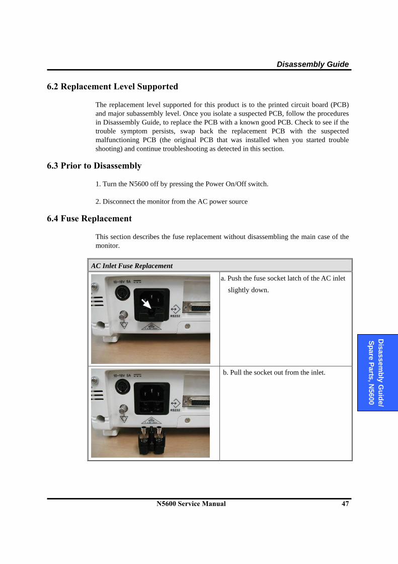
Disassembly Guide
N5600 Service Manual 47
D
isassembly G
uide/ Spare Parts, N
5600
6.2 Replacement Level Supported The replacement level supported for this product is to the printed circuit board (PCB) and major subassembly level. Once you isolate a suspected PCB, follow the procedures in Disassembly Guide, to replace the PCB with a known good PCB. Check to see if the trouble symptom persists, swap back the replacement PCB with the suspected malfunctioning PCB (the original PCB that was installed when you started trouble shooting) and continue troubleshooting as detected in this section.
6.3 Prior to Disassembly
1. Turn the N5600 off by pressing the Power On/Off switch. 2. Disconnect the monitor from the AC power source
6.4 Fuse Replacement This section describes the fuse replacement without disassembling the main case of the monitor.
AC Inlet Fuse Replacement
a. Push the fuse socket latch of the AC inlet
slightly down.
b. Pull the socket out from the inlet.
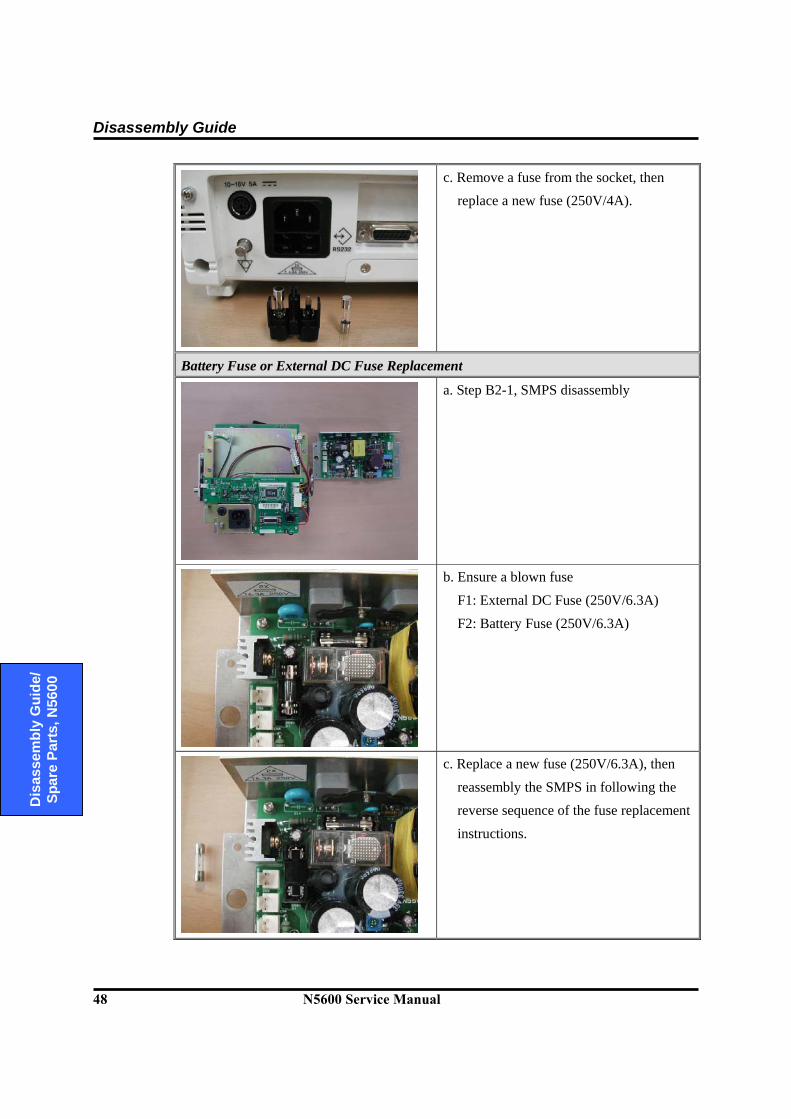
Disassembly Guide
48 N5600 Service Manual
D
isas
sem
bly
Gui
de/
Spar
e Pa
rts, N
5600
c. Remove a fuse from the socket, then replace a new fuse (250V/4A).
Battery Fuse or External DC Fuse Replacement
a. Step B2-1, SMPS disassembly
b. Ensure a blown fuse
F1: External DC Fuse (250V/6.3A)
F2: Battery Fuse (250V/6.3A)
c. Replace a new fuse (250V/6.3A), then
reassembly the SMPS in following the reverse sequence of the fuse replacement
instructions.
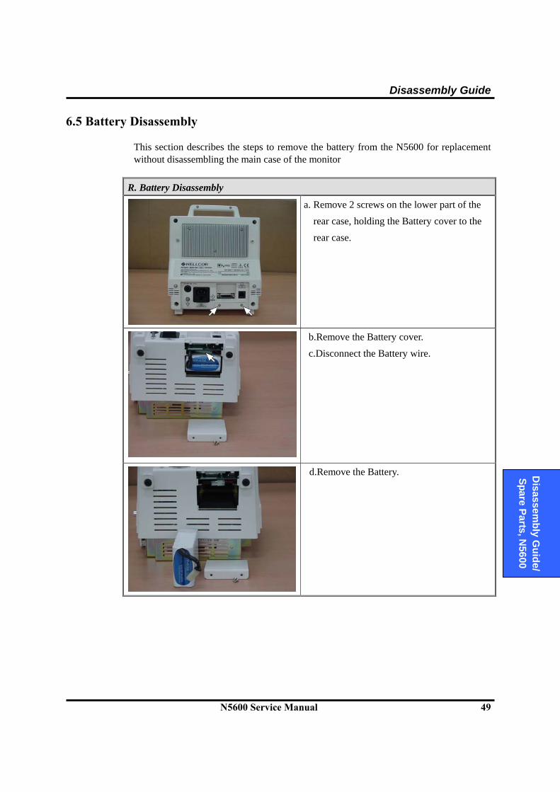
Disassembly Guide
N5600 Service Manual 49
D
isassembly G
uide/ Spare Parts, N
5600
6.5 Battery Disassembly This section describes the steps to remove the battery from the N5600 for replacement without disassembling the main case of the monitor
R. Battery Disassembly
a. Remove 2 screws on the lower part of the
rear case, holding the Battery cover to the
rear case.
b.Remove the Battery cover.
c.Disconnect the Battery wire.
d.Remove the Battery.

Disassembly Guide
50 N5600 Service Manual
D
isas
sem
bly
Gui
de/
Spar
e Pa
rts, N
5600
6.6 Monitor Disassembly This section describes the steps to separate the front and rear case assemblies.
Before the steps A and B;
a. Remove the monitor’s 6 screws.
b. Separate the front case from the rear case. c. Turn down the grabbers of the Main board
cable connector on the Main PCB to
disconnect the Main board cable from the
Main PCB. d. Disconnect the NIBP cable from the Main
PCB.

Disassembly Guide
N5600 Service Manual 51
D
isassembly G
uide/ Spare Parts, N
5600
6.7 Front Case Disassembly Procedures
This section describes the items that may be removed on the front case assembly.
A. Front Case Disassembly
A1. To remove the LCD Bracket from the front case
a. Disconnect the Encoder wire, the Function
switch board wire and the Power switch board wire from the Main PCB.
b. Remove 4 corner screws on the LCD
Bracket.
c. Remove the LCD Bracket from the front
case.
A1-1. Main PCB Disassembly
a. Disconnect the Inverter wire and the LED Board wire from the Main PCB.
b. Remove 4 screws on the Main PCB.
c. Remove the Bridge bracket from the Main
PCB. d. Remove the LCD cable from the Main
PCB.
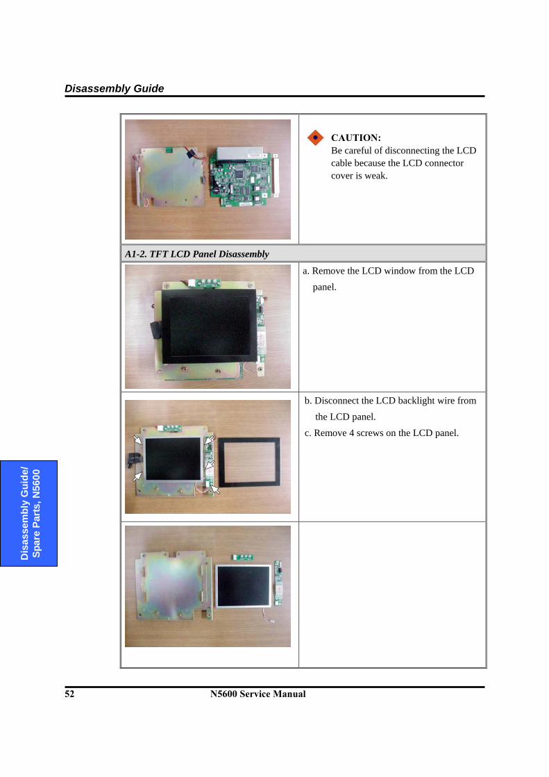
Disassembly Guide
52 N5600 Service Manual
D
isas
sem
bly
Gui
de/
Spar
e Pa
rts, N
5600
CAUTION: Be careful of disconnecting the LCD cable because the LCD connector cover is weak.
A1-2. TFT LCD Panel Disassembly
a. Remove the LCD window from the LCD
panel.
b. Disconnect the LCD backlight wire from
the LCD panel.
c. Remove 4 screws on the LCD panel.

Disassembly Guide
N5600 Service Manual 53
D
isassembly G
uide/ Spare Parts, N
5600
A1-3. LCD Backlight Inverter Disassembly
a. Disconnect the LCD backlight wire and
the Inverter wire from the Backlight inverter.
b. Remove 2 screws on the Backlight
inverter
A1-4. Alarm LED PCB Disassembly
a. Disconnect the Alarm LED board wire
from the Alarm LED PCB.
b. Remove 2 screws on the Alarm LED PCB.

Disassembly Guide
54 N5600 Service Manual
D
isas
sem
bly
Gui
de/
Spar
e Pa
rts, N
5600
A2-1. Knob, Encoder Disassembly
a. Pull the Knob straight out from the front
case.
CAUTION: Be careful when pulling the Knob
because the Encoder may be damaged.
b. Turn the Encoder to the left in order to
remove the Encoder from the front case.
A2-2. Function Switch PCB Disassembly
a. Remove 5 screws on the Function switch
PCB.
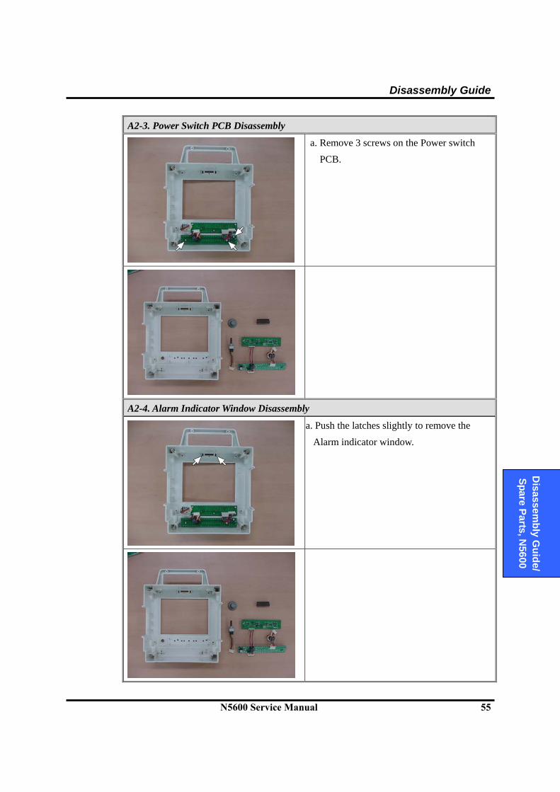
Disassembly Guide
N5600 Service Manual 55
D
isassembly G
uide/ Spare Parts, N
5600
A2-3. Power Switch PCB Disassembly
a. Remove 3 screws on the Power switch
PCB.
A2-4. Alarm Indicator Window Disassembly
a. Push the latches slightly to remove the
Alarm indicator window.

Disassembly Guide
56 N5600 Service Manual
D
isas
sem
bly
Gui
de/
Spar
e Pa
rts, N
5600
6.8 Rear Case Disassembly Procedures This section describes the steps to disassemble the rear case assembly.
B. Rear Case Disassembly
B1. SMPS Bracket Disassembly
a. Remove 4 screws and washers on the rear
case.
b. Separate the rear case from the rear case assembly.
B1-1. SMPS Disassembly
a. Remove 4 corner screws on the SMPS.
b. Disconnect the AC inlet wire and the
SMPS to Rear board DC wire, the
Battery wire and the External DC input wire from the SMPS.
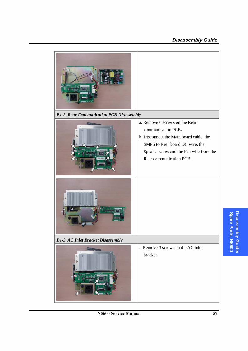
Disassembly Guide
N5600 Service Manual 57
D
isassembly G
uide/ Spare Parts, N
5600
B1-2. Rear Communication PCB Disassembly
a. Remove 6 screws on the Rear
communication PCB.
b. Disconnect the Main board cable, the
SMPS to Rear board DC wire, the Speaker wires and the Fan wire from the
Rear communication PCB.
B1-3. AC Inlet Bracket Disassembly
a. Remove 3 screws on the AC inlet bracket.
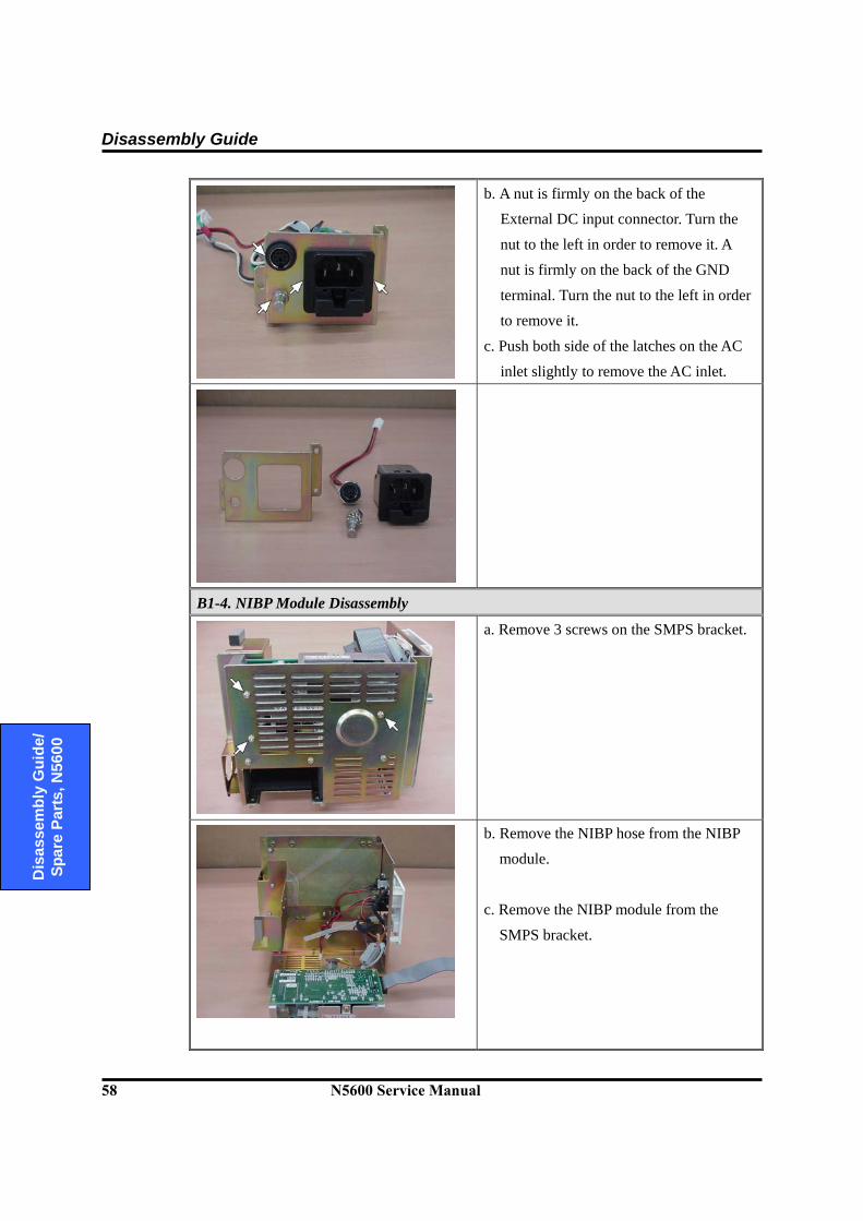
Disassembly Guide
58 N5600 Service Manual
D
isas
sem
bly
Gui
de/
Spar
e Pa
rts, N
5600
b. A nut is firmly on the back of the External DC input connector. Turn the
nut to the left in order to remove it. A
nut is firmly on the back of the GND
terminal. Turn the nut to the left in order to remove it.
c. Push both side of the latches on the AC
inlet slightly to remove the AC inlet.
B1-4. NIBP Module Disassembly
a. Remove 3 screws on the SMPS bracket.
b. Remove the NIBP hose from the NIBP
module.
c. Remove the NIBP module from the
SMPS bracket.
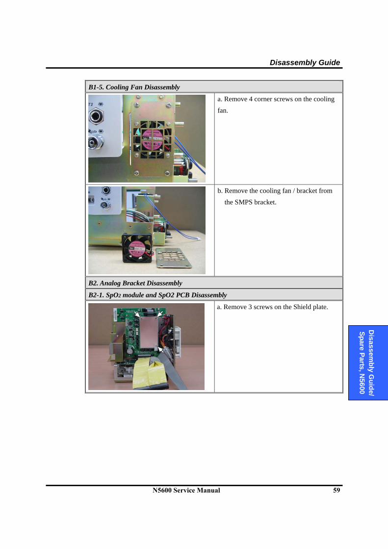
Disassembly Guide
N5600 Service Manual 59
D
isassembly G
uide/ Spare Parts, N
5600
B1-5. Cooling Fan Disassembly
a. Remove 4 corner screws on the cooling
fan.
b. Remove the cooling fan / bracket from
the SMPS bracket.
B2. Analog Bracket Disassembly
B2-1. SpO2 module and SpO2 PCB Disassembly
a. Remove 3 screws on the Shield plate.
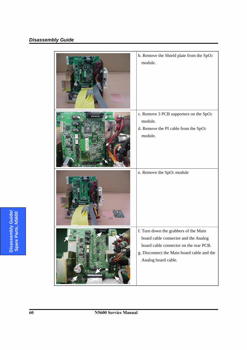
Disassembly Guide
60 N5600 Service Manual
D
isas
sem
bly
Gui
de/
Spar
e Pa
rts, N
5600
b. Remove the Shield plate from the SpO2 module.
c. Remove 3 PCB supporters on the SpO2
module.
d. Remove the PI cable from the SpO2
module.
e. Remove the SpO2 module
f. Turn down the grabbers of the Main
board cable connector and the Analog board cable connector on the rear PCB.
g. Disconnect the Main board cable and the
Analog board cable.

Disassembly Guide
N5600 Service Manual 61
D
isassembly G
uide/ Spare Parts, N
5600
h. Remove the SpO2 PCB.
B2-2. ECG PCB Disassembly
a. Disconnect the ECG wire and the
Temperature wires from the ECG PCB.
b. Remove 4 corner screws on the ECG
PCB. c. Remove the PCB supporters on the ECG
PCB.
d. Remove the ECG PCB.
B2-3. Speakers Disassembly
a. Remove 2 screws on both side of each speaker.
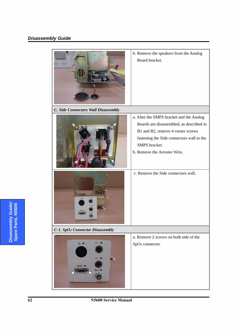
Disassembly Guide
62 N5600 Service Manual
D
isas
sem
bly
Gui
de/
Spar
e Pa
rts, N
5600
b. Remove the speakers from the Analog Board bracket.
C. Side Connectors Wall Disassembly
a. After the SMPS bracket and the Analog
Boards are disassembled, as described in
B1 and B2, remove 4 corner screws
fastening the Side connectors wall to the SMPS bracket.
b. Remove the Arrester Wire.
c. Remove the Side connectors wall.
C-1. SpO2 Connector Disassembly
a. Remove 2 screws on both side of the SpO2 connector.
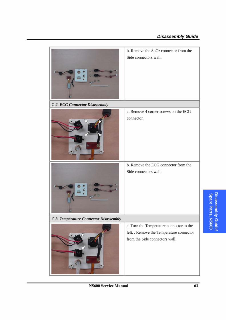
Disassembly Guide
N5600 Service Manual 63
D
isassembly G
uide/ Spare Parts, N
5600
b. Remove the SpO2 connector from the Side connectors wall.
C-2. ECG Connector Disassembly
a. Remove 4 corner screws on the ECG
connector.
b. Remove the ECG connector from the
Side connectors wall.
C-3. Temperature Connector Disassembly
a. Turn the Temperature connector to the left. . Remove the Temperature connector
from the Side connectors wall.

Disassembly Guide
64 N5600 Service Manual
D
isas
sem
bly
Gui
de/
Spar
e Pa
rts, N
5600
C-4. NIBP Connector Disassembly
a. Remove the NIBP hose from the NIBP
connector.
b. Turn to the left a nut fastening the NIBP
connector.
c. Remove the NIBP connector from the
Side connectors wall.

Disassembly Guide
N5600 Service Manual 65
D
isassembly G
uide/ Spare Parts, N
5600
6.9 Optional Printer Assembly/Disassembly Procedures
This section describes the steps that may remove an optional printer in the N5600. If you would like to install a printer, follow the reverse sequence of the procedures.
B3. Printer Disassembly
The rear case separated from the front case
a. Disconnect the printer wire from the SpO2 PCB and the Printer.
b. Open the printer door and remove print
paper.

Disassembly Guide
66 N5600 Service Manual
D
isas
sem
bly
Gui
de/
Spar
e Pa
rts, N
5600
B3. Printer Disassembly
c. Remove 2 screws inside the Printer door.
d. Remove the Printer.
Section 7: Spare Parts
7.1 Introduction 7.2 Obtaining Replacement Parts 7.3 Parts List
N5600 Service Manual 67
D
isassembly G
uide/ Spare Parts, N
5600
WARNING: Follow local government ordinances and recycle instructions regarding disposal or recycling of device components, including batteries.
7.1 Introduction
Spare parts, along with part numbers, are shown in Table 20. “Item No.” corresponds to the circled callout numbers in Figure 8.
7.2 Obtaining Replacement Parts
Tyco Healthcare Technical Service provides technical assistance information and replacement parts. To obtain replacement parts, contact Tyco Healthcare or your local Tyco Healthcare representative. Refer to parts by the part names and part numbers.
7.3 Parts List
Tyco Healthcare Technical Service provides technical assistance information and replacement parts. To obtain replacement parts, contact Tyco Healthcare or your local Tyco Healthcare representative. Refer to parts by part numbers and part names.
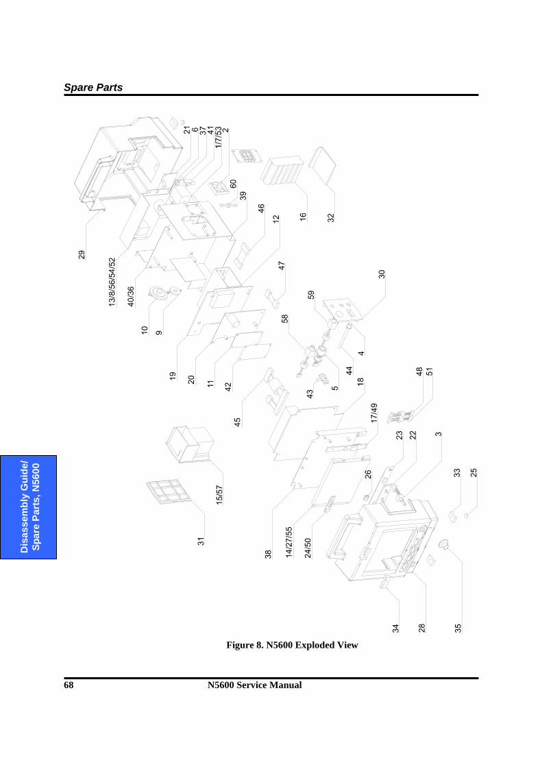
Spare Parts
68 N5600 Service Manual
D
isas
sem
bly
Gui
de/
Spar
e Pa
rts, N
5600
Figure 8. N5600 Exploded View
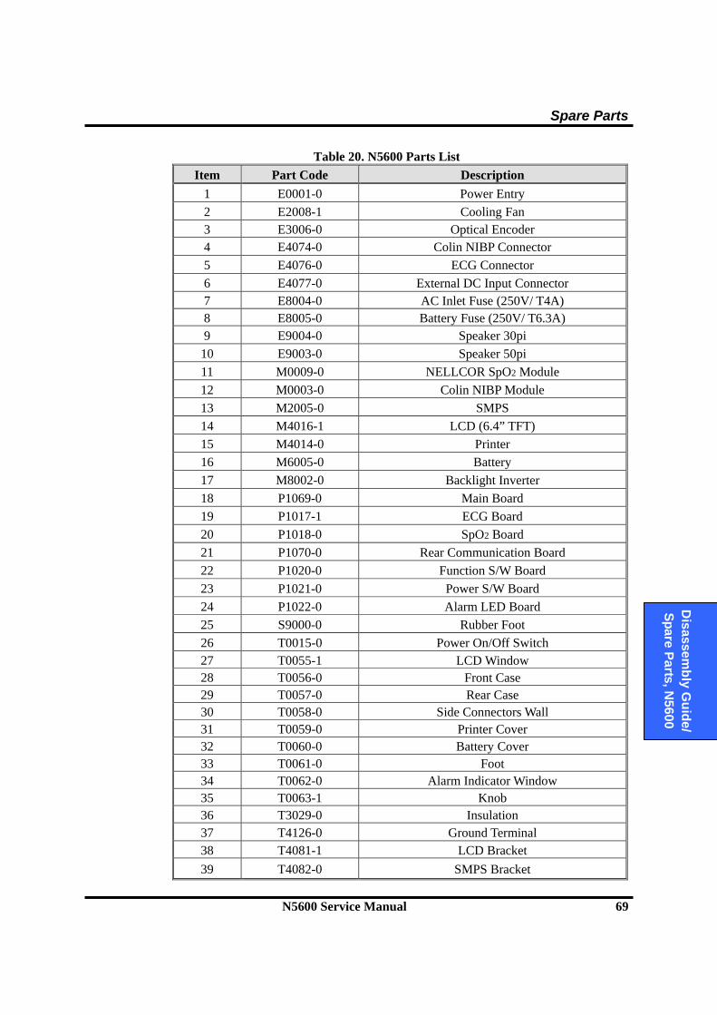
Spare Parts
N5600 Service Manual 69
D
isassembly G
uide/ Spare Parts, N
5600
Table 20. N5600 Parts List Item Part Code Description
1 E0001-0 Power Entry 2 E2008-1 Cooling Fan 3 E3006-0 Optical Encoder 4 E4074-0 Colin NIBP Connector 5 E4076-0 ECG Connector 6 E4077-0 External DC Input Connector 7 E8004-0 AC Inlet Fuse (250V/ T4A) 8 E8005-0 Battery Fuse (250V/ T6.3A) 9 E9004-0 Speaker 30pi 10 E9003-0 Speaker 50pi 11 M0009-0 NELLCOR SpO2 Module 12 M0003-0 Colin NIBP Module 13 M2005-0 SMPS 14 M4016-1 LCD (6.4” TFT) 15 M4014-0 Printer 16 M6005-0 Battery 17 M8002-0 Backlight Inverter 18 P1069-0 Main Board 19 P1017-1 ECG Board 20 P1018-0 SpO2 Board 21 P1070-0 Rear Communication Board 22 P1020-0 Function S/W Board 23 P1021-0 Power S/W Board 24 P1022-0 Alarm LED Board 25 S9000-0 Rubber Foot 26 T0015-0 Power On/Off Switch 27 T0055-1 LCD Window 28 T0056-0 Front Case 29 T0057-0 Rear Case 30 T0058-0 Side Connectors Wall 31 T0059-0 Printer Cover 32 T0060-0 Battery Cover 33 T0061-0 Foot 34 T0062-0 Alarm Indicator Window 35 T0063-1 Knob 36 T3029-0 Insulation 37 T4126-0 Ground Terminal 38 T4081-1 LCD Bracket 39 T4082-0 SMPS Bracket
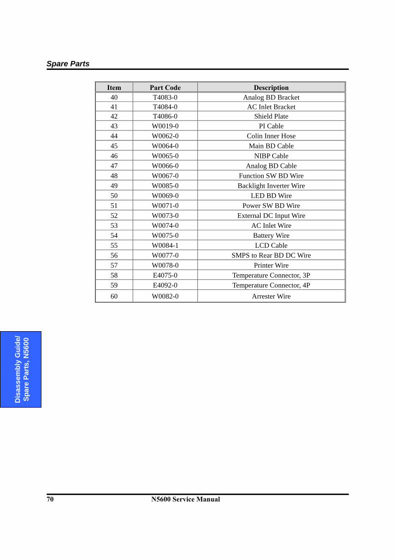
Spare Parts
70 N5600 Service Manual
D
isas
sem
bly
Gui
de/
Spar
e Pa
rts, N
5600
Item Part Code Description 40 T4083-0 Analog BD Bracket 41 T4084-0 AC Inlet Bracket 42 T4086-0 Shield Plate 43 W0019-0 PI Cable 44 W0062-0 Colin Inner Hose 45 W0064-0 Main BD Cable 46 W0065-0 NIBP Cable 47 W0066-0 Analog BD Cable 48 W0067-0 Function SW BD Wire 49 W0085-0 Backlight Inverter Wire 50 W0069-0 LED BD Wire 51 W0071-0 Power SW BD Wire 52 W0073-0 External DC Input Wire 53 W0074-0 AC Inlet Wire 54 W0075-0 Battery Wire 55 W0084-1 LCD Cable 56 W0077-0 SMPS to Rear BD DC Wire 57 W0078-0 Printer Wire 58 E4075-0 Temperature Connector, 3P 59 E4092-0 Temperature Connector, 4P 60 W0082-0 Arrester Wire
Section 8: Packing For Shipment
8.1 General Instructions 8.2 Returning the N5600 8.3 Repacking In Original Carton 8.4 Repacking In a Different Carton
N5600 Service Manual 71
D
isassembly G
uide/ Spare Parts, N
5600
8.1 General Instructions
To ship the monitor for any reason, follow the instructions in this section. Pack the monitor carefully. Failure to follow the instructions in this section may result in loss or damage not covered by the Tyco Healthcare warranty. If the original shipping carton is not available, use another suitable carton; North American customers may call Tyco Healthcare Technical Services to obtain a shipping carton. Prior to shipping the monitor, contact your supplier or the local Tyco Healthcare office (Technical Services Department) for a returned goods authorization (RGA) number. Mark the shipping carton and any shipping documents with the returned goods authorization number. Pack to shipping the monitor, contact your supplier or local Tyco Healthcare office (Technical Services Department) for a returned goods authorization number. Mark the shipping carton and any shipping documents with the returned goods authorization (RGA) number. Return the N5600 by any method that provides proof of delivery.
8.2 Returning the N5600
Contact Tyco Healthcare Technical Services Department or your local Tyco Healthcare representative for shipping instructions, including a Returned Goods Authorization (RGA) number. Unless otherwise instructed by Tyco Healthcare Technical Services Department, it is not necessary to return the sensor or other accessory items with the monitor. Pack the N5600 in its original shipping carton. If the original carton is not available, use a suitable carton with appropriate packing material to protect it during shipping.
8.3 Repacking In Original Carton
If available, use the original carton and packing materials. Pack the monitor as follows: 1. Place the monitor and, if necessary, accessory items in original packaging. 2. Place in shipping carton and seal carton with packaging tape. 3. Label carton with shipping address, return address and RGA number, if applicable.
Packing For Shipment
72 N5600 Service Manual
D
isas
sem
bly
Gui
de/
Spar
e Pa
rts, N
5600
8.4 Repacking In a Different Carton If the original carton is not available, use the following procedure to pack the N5600: 1. Place the monitor in a plastic bag. 2. Locate a corrugated cardboard shipping carton with at least 200 pounds per square
inch (psi) bursting strength. 3. Fill the bottom of the carton with at least 2 inches of packing material. 4. Place the bagged unit on the layer of packing material and fill the box completely
with packing material. 5. Seal the carton with packing tape.
6. Label the carton with the shipping address, return address, and RGA number, if
applicable.

Section 9: Specification
9.1 Display 9.2 Controls 9.3 Alarms 9.4 Physical Characteristics and Printer 9.5 Electrical 9.6 Environmental 9.7 Measuring Parameters 9.8 Trends 9.9 Compliances
N5600 Service Manual 73
Technical
Information, N
5600
9.1 Display
Screen Size 130.56 mm × 97.92 mm (6.425 inch)
Screen Type/Color Liquid Crystal Display (LCD) Color, Cold Cathode Fluorescent Backlit
Resolution 640 × 480 pixel Number of traces 3 Waveforms (Maximum)
9.2 Controls
Standard Trim Knob control; 5 soft switches (Power On/Off, NIBP start/stop, Record, Home, Alarm Silence/Suspend)
9.3 Alarms
Categories Patient Status and System Status Priorities Low, Medium, and High Priorities Notification Audible and Visual Setting Default and Individual
9.4 Physical
Instrument Dimensions 230×230×275 (mm) (W×D×H)
including a handle and excluding options and accessories Weight 5.0 (kg) excluding options and accessories
Printer (Optional) Type Thermal Weight 0.4 (kg) Resolution 200 dpi (8 dot/mm) Number of channels 1 to 2 channels Paper Width 50 mm Paper Speeds 25.0 mm/s and 50.0 mm/s
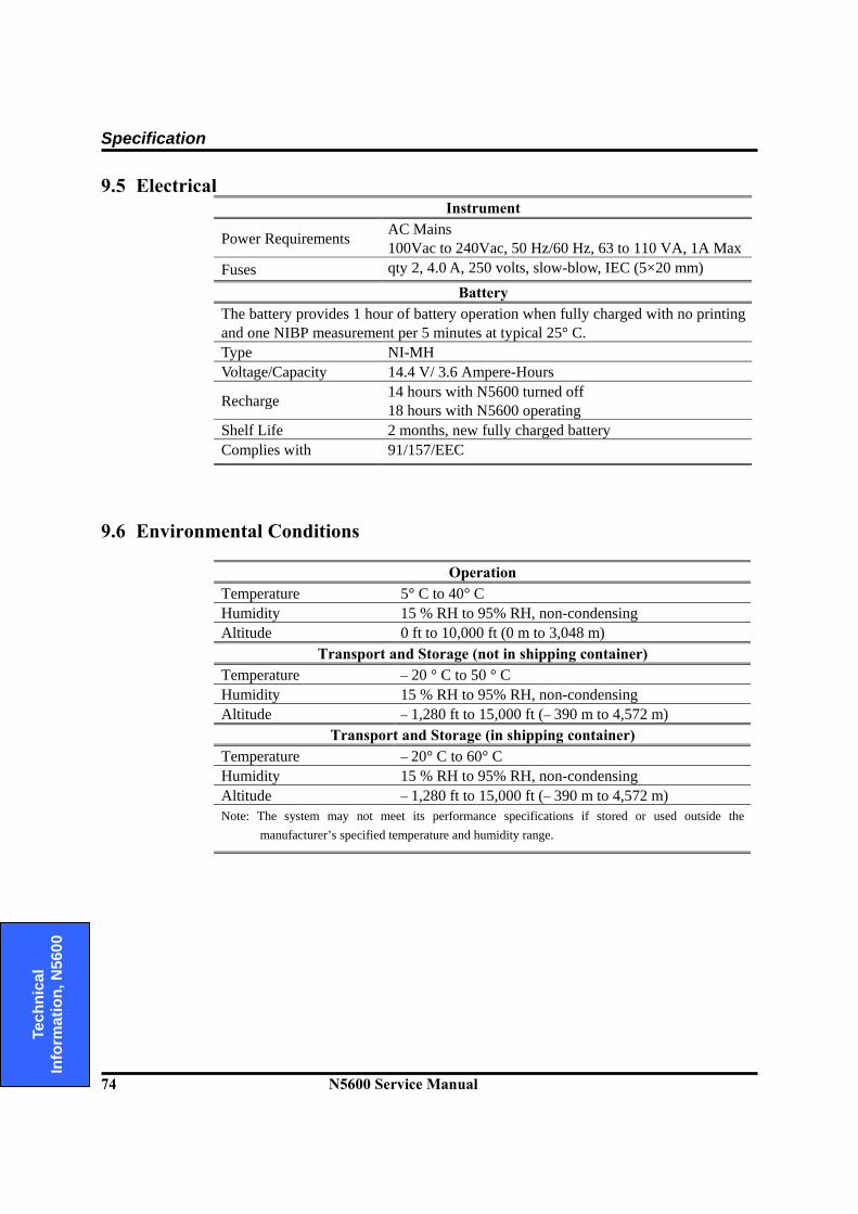
Specification
74 N5600 Service Manual
Te
chni
cal
Info
rmat
ion,
N56
00
9.5 Electrical Instrument
Power Requirements AC Mains 100Vac to 240Vac, 50 Hz/60 Hz, 63 to 110 VA, 1A Max
Fuses qty 2, 4.0 A, 250 volts, slow-blow, IEC (5×20 mm) Battery
The battery provides 1 hour of battery operation when fully charged with no printing and one NIBP measurement per 5 minutes at typical 25° C. Type NI-MH Voltage/Capacity 14.4 V/ 3.6 Ampere-Hours
Recharge 14 hours with N5600 turned off 18 hours with N5600 operating
Shelf Life 2 months, new fully charged battery Complies with 91/157/EEC
9.6 Environmental Conditions
Operation Temperature 5° C to 40° C Humidity 15 % RH to 95% RH, non-condensing Altitude 0 ft to 10,000 ft (0 m to 3,048 m)
Transport and Storage (not in shipping container) Temperature – 20 ° C to 50 ° C Humidity 15 % RH to 95% RH, non-condensing Altitude – 1,280 ft to 15,000 ft (– 390 m to 4,572 m)
Transport and Storage (in shipping container) Temperature – 20° C to 60° C Humidity 15 % RH to 95% RH, non-condensing Altitude – 1,280 ft to 15,000 ft (– 390 m to 4,572 m) Note: The system may not meet its performance specifications if stored or used outside the
manufacturer’s specified temperature and humidity range.
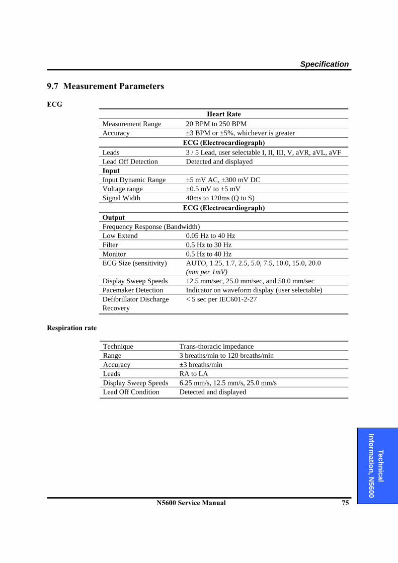
Specification
N5600 Service Manual 75
Technical
Information, N
5600
9.7 Measurement Parameters ECG
Heart Rate Measurement Range 20 BPM to 250 BPM Accuracy ±3 BPM or ±5%, whichever is greater
ECG (Electrocardiograph) Leads 3 / 5 Lead, user selectable I, II, III, V, aVR, aVL, aVF Lead Off Detection Detected and displayed Input Input Dynamic Range ±5 mV AC, ±300 mV DC Voltage range ±0.5 mV to ±5 mV Signal Width 40ms to 120ms (Q to S)
ECG (Electrocardiograph) Output Frequency Response (Bandwidth) Low Extend 0.05 Hz to 40 Hz Filter 0.5 Hz to 30 Hz Monitor 0.5 Hz to 40 Hz ECG Size (sensitivity) AUTO, 1.25, 1.7, 2.5, 5.0, 7.5, 10.0, 15.0, 20.0
(mm per 1mV) Display Sweep Speeds 12.5 mm/sec, 25.0 mm/sec, and 50.0 mm/sec Pacemaker Detection Indicator on waveform display (user selectable) Defibrillator Discharge Recovery
< 5 sec per IEC601-2-27
Respiration rate
Technique Trans-thoracic impedance Range 3 breaths/min to 120 breaths/min Accuracy ±3 breaths/min Leads RA to LA Display Sweep Speeds 6.25 mm/s, 12.5 mm/s, 25.0 mm/s Lead Off Condition Detected and displayed
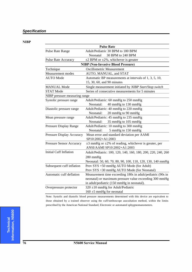
Specification
76 N5600 Service Manual
Te
chni
cal
Info
rmat
ion,
N56
00
NIBP Pulse Rate
Pulse Rate Range Adult/Pediatric 30 BPM to 180 BPM Neonatal 30 BPM to 240 BPM
Pulse Rate Accuracy ±2 BPM or ±2%, whichever is greater NIBP (Non-Invasive Blood Pressure)
Technique Oscillometric Measurement Measurement modes AUTO, MANUAL, and STAT AUTO Mode Automatic BP measurements at intervals of 1, 3, 5, 10,
15, 30, 60, and 90 minutes MANUAL Mode Single measurement initiated by NIBP Start/Stop switch STAT Mode Series of consecutive measurements for 5 minutes NIBP pressure measuring range Systolic pressure range Adult/Pediatric: 60 mmHg to 250 mmHg
Neonatal: 40 mmHg to 130 mmHg Diastolic pressure range Adult/Pediatric: 40 mmHg to 220 mmHg
Neonatal: 20 mmHg to 90 mmHg Mean pressure range Adult/Pediatric: 45 mmHg to 235 mmHg
Neonatal: 35 mmHg to 105 mmHg Pressure Display Range Adult/Pediatric: 10 mmHg to 300 mmHg
Neonatal: 5 mmHg to 150 mmHg Pressure Display Accuracy Mean error and standard deviation per AAMI
SP10:2002+A1:2003 Pressure Sensor Accuracy ±3 mmHg or ±2% of reading, whichever is greater, per
ANSI/AAMI SP10:2002+A1:2003 Initial Cuff Inflation Adult/Pediatric: 100, 120, 140, 160, 180, 200, 220, 240, 260
280 mmHg Neonatal: 50, 60, 70, 80, 90, 100, 110, 120, 130, 140 mmHg
Subsequent cuff inflation Prev SYS +50 mmHg AUTO Mode (for Adult) Prev SYS +30 mmHg AUTO Mode (for Neonatal)
Automatic cuff deflation Measurement time exceeding 180s in adult/pediatric (90s in neonatal) or maximum pressure value exceeding 300 mmHg in adult/pediatric (150 mmHg in neonatal).
Overpressure protector 320 ±10 mmHg for Adult/Pediatric 160 ±5 mmHg for neonatal
Note: Systolic and diastolic blood pressure measurements determined with this device are equivalent to those obtained by a trained observer using the cuff/stethoscope auscultation method, within the limits prescribed by the American National Standard, Electronic or automated sphygmomanometers.

Specification
N5600 Service Manual 77
Technical
Information, N
5600
SpO2 %Saturation
Range 1% to 100% Low Perfusion 0.03% to 20% Accuracy Without Interference-Adults1 70% to 100% ±2 digits
Without Interference-Neonate1 70% to 100% ±3 digits 1% to 69% unspecified
With Interference2 -Adults/Neonate 70% to 100% ±3 digits Low Perfusion3 70% to 100% ±2 digits
1% to 69% unspecified Display Sweep Speeds 12.5 mm/sec, 25.0 mm/sec, and 50.0 mm/sec
Pulse Rate Range 20 BPM to 250 BPM Accuracy Without Interference 20 BPM to 250 BPM ±3 digits
With Interference normal physiologic range (55 to 125 BPM) ±5 digits
Low Perfusion3 20 BPM to 250 BPM ±3 digits 1Adult specification are shown for OxiMax MAX-A and MAX-N sensors with the N5600. Neonate specifications are shown for OxiMax MAX-N sensors with the N5600. Saturation accuracy will vary by sensor type.
2Applicability(accuracy with motion): OxiMax sensors. 3Specification applies to monitor performance and was validated with Biotek and Nellcor simulators
Temperature
Probe Type Thermistor probe (Monotherm™ temperature probes) Parameter displayed T1, T2 Range 15° C to 45° C Display Accuracy ±0.1° C (25° C to 45° C)
±0.2° C (15° C to less than 25° C) Probe Accuracy ±0.1° C
9.8 Trends
Types Graphical and Tabular Memory Storage 24 hours, nonvolatile, 20 seconds data interval Graphical Format One graph for all parameters
Also user-selectable each parameter to be desired Display Range 2 hours Tabular Format One table for all variables.
18 rows (date, parameter labels, and 16 variable rows) Display Time Interval 20sec, 1min, 2min, 3min, 5min, 10min, 15min, 20min
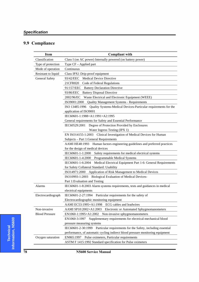
Specification
78 N5600 Service Manual
Te
chni
cal
Info
rmat
ion,
N56
00
9.9 Compliance
Item Compliant with Classification Class I (on AC power) Internally powered (on battery power) Type of protection Type CF – Applied part Mode of operation Continuous Resistant to liquid Class IPX1 Drip-proof equipment General Safety 93/42/EEC Medical Device Directive 21CFR820 Code of Federal Regulations 91/157/EEC Battery Declaration Directive 93/86/EEC Battery Disposal Directive 2002/96/EC Waste Electrical and Electronic Equipment (WEEE) ISO9001:2000 Quality Management Systems - Requirements ISO 13485:1996 Quality Systems-Medical Devices-Particular requirements for the
application of ISO9001 IEC60601-1:1988+A1:1991+A2:1995
General requirements for Safety and Essential Performance IEC60529:2001 Degree of Protection Provided by Enclosures
Water Ingress Testing (IPX 1) EN ISO14155-1:2003 Clinical Investigation of Medical Devices for Human
Subjects – Part 1:General Requirements AAMI HE48:1993 Human factors engineering guidelines and preferred practices
for the design of medical devices IEC60601-1-1:2000 Safety requirements for medical electrical systems IEC60601-1-4:2000 Programmable Medical Systems IEC60601-1-6:2004 Medical Electrical Equipment Part 1-6: General Requirements
for Safety Collateral Standard: Usability ISO14971:2000 Application of Risk Management to Medical Devices ISO10993-1:2003 Biological Evaluation of Medical Devices-
Part 1:Evaluation and Testing Alarms IEC60601-1-8:2003 Alarm systems requirements, tests and guidances in medical
electrical equipments Electrocardiograph IEC60601-2-27:1994 Particular requirements for the safety of
Electrocardiographic monitoring equipment AAMI EC53:1995+A1:1998 ECG cables and leadwires Non-invasive AAMI SP10:2002+A1:2003 Electronic or Automated Sphygmomanometers Blood Pressure EN1060-1:1995+A1:2002 Non-invasive sphygmomanometers EN1060-3:1997 Supplementary requirements for electrical-mechanical blood
pressure measuring systems IEC60601-2-30:1999 Particular requirements for the Safety, including essential
performance, of automatic cycling indirect blood pressure monitoring equipment Oxygen saturation EN865:1997 Pulse oximeters, Particular requirements ASTM F 1415:1992 Standard specification for Pulse oximeters
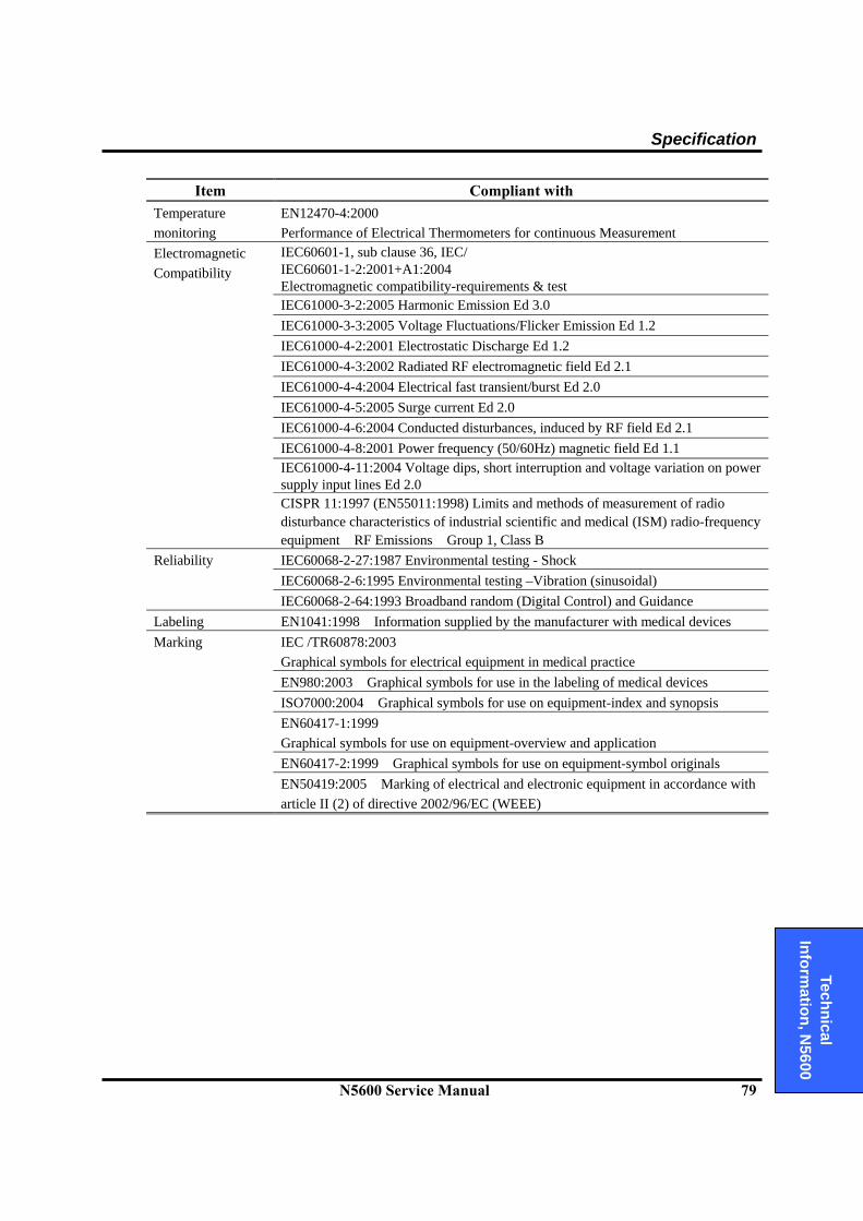
Specification
N5600 Service Manual 79
Technical
Information, N
5600
Item Compliant with Temperature monitoring
EN12470-4:2000 Performance of Electrical Thermometers for continuous Measurement
Electromagnetic Compatibility
IEC60601-1, sub clause 36, IEC/ IEC60601-1-2:2001+A1:2004 Electromagnetic compatibility-requirements & test
IEC61000-3-2:2005 Harmonic Emission Ed 3.0 IEC61000-3-3:2005 Voltage Fluctuations/Flicker Emission Ed 1.2 IEC61000-4-2:2001 Electrostatic Discharge Ed 1.2 IEC61000-4-3:2002 Radiated RF electromagnetic field Ed 2.1 IEC61000-4-4:2004 Electrical fast transient/burst Ed 2.0 IEC61000-4-5:2005 Surge current Ed 2.0 IEC61000-4-6:2004 Conducted disturbances, induced by RF field Ed 2.1 IEC61000-4-8:2001 Power frequency (50/60Hz) magnetic field Ed 1.1 IEC61000-4-11:2004 Voltage dips, short interruption and voltage variation on power
supply input lines Ed 2.0 CISPR 11:1997 (EN55011:1998) Limits and methods of measurement of radio
disturbance characteristics of industrial scientific and medical (ISM) radio-frequency equipment RF Emissions Group 1, Class B
Reliability IEC60068-2-27:1987 Environmental testing - Shock IEC60068-2-6:1995 Environmental testing –Vibration (sinusoidal) IEC60068-2-64:1993 Broadband random (Digital Control) and Guidance Labeling EN1041:1998 Information supplied by the manufacturer with medical devices Marking IEC /TR60878:2003
Graphical symbols for electrical equipment in medical practice EN980:2003 Graphical symbols for use in the labeling of medical devices ISO7000:2004 Graphical symbols for use on equipment-index and synopsis EN60417-1:1999
Graphical symbols for use on equipment-overview and application EN60417-2:1999 Graphical symbols for use on equipment-symbol originals EN50419:2005 Marking of electrical and electronic equipment in accordance with
article II (2) of directive 2002/96/EC (WEEE)

Specification
80 N5600 Service Manual
Te
chni
cal
Info
rmat
ion,
N56
00
This page is intentionally left blank.

Section 10: System Processing Description
10.1 System Overview 10.2 System Block Diagram 10.3 ECG Processing 10.4 NIBP Processing 10.5 SpO2 Processing 10.6 Respiration Processing 10.7 Temperature Processing
N5600 Service Manual 81
Technical
Information, N
5600
10.1 System Overview
The N5600 patient monitor is a multi-function monitor for use on adult, pediatric and neonatal patients; ECG, heart rate, non invasive blood pressures, arterial oxygen saturation, pulse rate, respiration rate and temperature. In addition to monitoring and displaying the status of these physiological parameters, the instrument performs various microprocessor-programmed analytical functions; Creating both visual and audible alarm signals when settable limits are violated; Creating and displaying warning/error messages when conditions are detected that
would degrade or prevent valid measurements; Creating and displaying graphical or tabular trend data; Providing input to an optional recorder for printout of current or tabular trend data.
The monitor is essentially a battery-powered instrument. An internal charging unit is designed to accept only an AC line voltage.
10.2 System Block Diagram
Processor UNITGUI UNIT
Communication UNIT
SOUND UNIT
DC/DC UNIT
POWER UNIT
ECG UNIT Respiration UNIT
NIBP UNIT
SpO2 UNIT Temperature UNIT
IOP UNIT
Thermal Printer UNIT
User Control UNIT
Analog Control UNIT
Figure 9. N5600 System Block Diagram 1
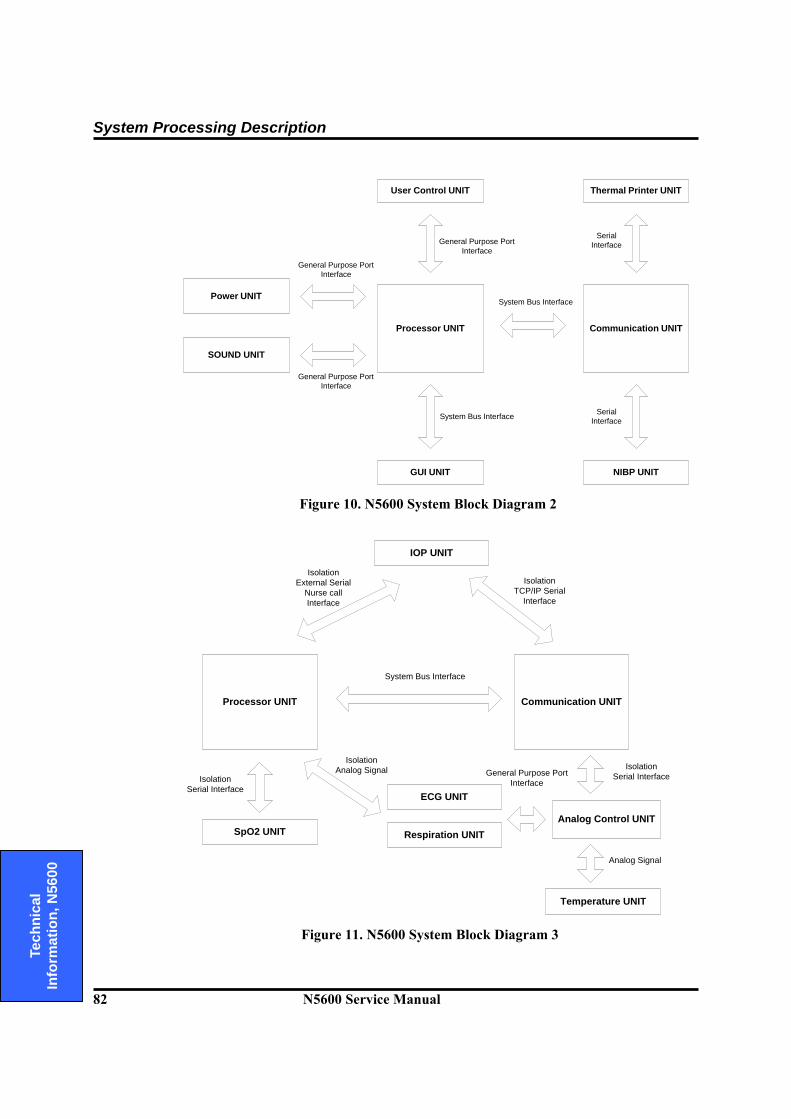
System Processing Description
82 N5600 Service Manual
Te
chni
cal
Info
rmat
ion,
N56
00
Processor UNIT
GUI UNIT
Communication UNIT
SOUND UNIT
NIBP UNIT
Thermal Printer UNITUser Control UNIT
Power UNIT
General Purpose PortInterface
System Bus Interface
System Bus Interface
General Purpose PortInterface
SerialInterface
SerialInterface
General Purpose PortInterface
Figure 10. N5600 System Block Diagram 2
ECG UNIT
Respiration UNITSpO2 UNIT
Temperature UNIT
IOP UNIT
Analog Control UNIT
Processor UNIT Communication UNIT
System Bus Interface
Isolation External Serial
Nurse callInterface
Isolation TCP/IP Serial
Interface
Isolation Analog Signal
Isolation Serial Interface
Isolation Serial InterfaceGeneral Purpose Port
Interface
Analog Signal
Figure 11. N5600 System Block Diagram 3
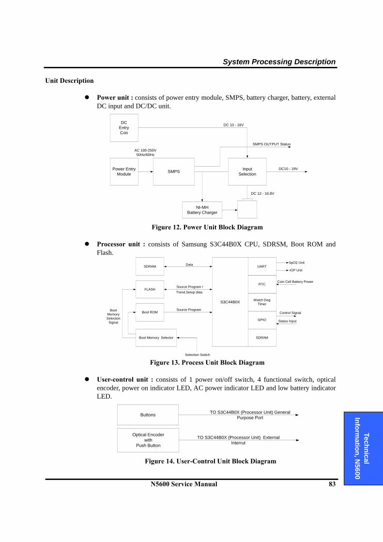
System Processing Description
N5600 Service Manual 83
Technical
Information, N
5600
Unit Description
Power unit : consists of power entry module, SMPS, battery charger, battery, external DC input and DC/DC unit.
SMPSPower EntryModule
AC 100-250V50Hz/60Hz
NI-MHBattery Charger
DCEntryCon
InputSelection
DC 10 - 16V
DC 12 - 16.8V
DC10 - 19V
SMPS OUTPUT Status
Figure 12. Power Unit Block Diagram
Processor unit : consists of Samsung S3C44B0X CPU, SDRSM, Boot ROM and
Flash.
S3C44B0X
SDRAM
BootMemorySelection
Signal
FLASH
Boot ROM
Boot Memory Selector
UART
RTC
Watch DogTimer
GPIO
SDRAM
Data
Source Program /
Source Program
Selection Switch
SpO2 Unit
IOP Unit
Coin Cell Battery Power
Control Signal
Status Input
Trend,Setup data
Figure 13. Process Unit Block Diagram
User-control unit : consists of 1 power on/off switch, 4 functional switch, optical
encoder, power on indicator LED, AC power indicator LED and low battery indicator LED.
Buttons
Optical Encoderwith
Push Button
TO S3C44B0X (Processor Unit) GeneralPurpose Port
TO S3C44B0X (Processor Unit) ExternalInterrut
Figure 14. User-Control Unit Block Diagram

System Processing Description
84 N5600 Service Manual
Te
chni
cal
Info
rmat
ion,
N56
00
Sound unit : consists of 8bit PIC micom, 2-channel amplifiers and speaker.
PIC 16C63A
Audio AMP 1
PWM OUT
Audio AMP 2Frequencyto Voltage
Conversion
Frequencyto VoltageConversion
PWM OUT
Sound Pulse
Sound Pulse
VolumeControl
VolumeControl
AlarmSpeaker
Pulse ToneSpeaker
Figure 15. Sound Unit Block Diagram
Communication unit : 4-channel UART
S3C44B0X System BUSUART
Asyncronous Serial Communication with NIBP UNIT
Asyncronous Serial Communication with Analog Control Unit
Asyncronous Serial Communication with TCP/IP UNIT
Asyncronous Serial Communication with Printer UNIT
Figure 16. Communication Unit Block Diagram
GUI (graphic user interface) unit : consists of TFT LCD, inverter for backlit and
internal video controller.
LEVELCONVERSION
&DAMPING RBYPASS C
LCDControlSignal S3C44B0X System BUS
LCD ControllerSED1385F0A
withVIDEO MEMORY
TFT LCD
INVERTERFOR
BACKLIGHT
LCDControlSignal
Figure 17. GUI Unit Block Diagram
Thermal Printer unit : prints data records.
Thermal PrinterError Signal
Asyncronous Serial Communication with Communication UNIT
Figure 18. Thermal Printer Unit Block Diagram
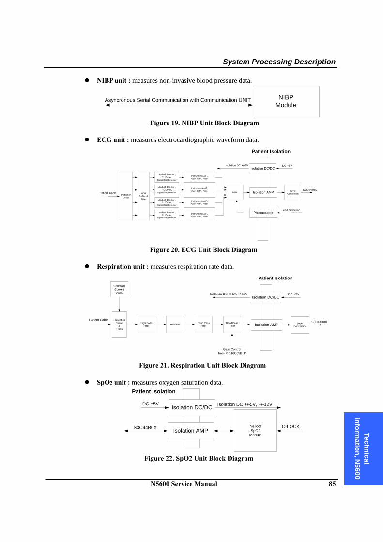
System Processing Description
N5600 Service Manual 85
Technical
Information, N
5600
NIBP unit : measures non-invasive blood pressure data.
NIBPModule
Asyncronous Serial Communication with Communication UNIT
Figure 19. NIBP Unit Block Diagram
ECG unit : measures electrocardiographic waveform data.
DC +5VIsolation DC/DC
Isolation DC +/-5V
Patient Isolation
Photocoupler
Isolation AMPInputBuffer &
Filter
ProtectionCircuit
Lead off detector ,RL Driver,
Signal Sat Detector
Instrument AMP,Gain AMP, Filter
Lead off detector ,RL Driver,
Signal Sat Detector
Lead off detector ,RL Driver,
Signal Sat Detector
Lead off detector ,RL Driver,
Signal Sat Detector
Instrument AMP,Gain AMP, Filter
Instrument AMP,Gain AMP, Filter
Instrument AMP,Gain AMP, Filter
MUX LevelConversionPatient Cable
Lead Selection
S3C44B0X
Figure 20. ECG Unit Block Diagram
Respiration unit : measures respiration rate data.
DC +5VIsolation DC/DC
Isolation DC +/-5V, +/-12V
Patient Isolation
Isolation AMP
ConstantCurrentSource
ProtectionCircuit
&Trans
High PassFilter Rectifier Level
Conversion
Patient CableS3C44B0XBand Pass
FilterBand Pass
Filter
Gain Controlfrom PIC16C65B_P
Figure 21. Respiration Unit Block Diagram SpO2 unit : measures oxygen saturation data.
DC +5VIsolation DC/DC Isolation DC +/-5V, +/-12V
Patient Isolation
Isolation AMPNellcorSpO2
Module
S3C44B0X C-LOCK
Figure 22. SpO2 Unit Block Diagram
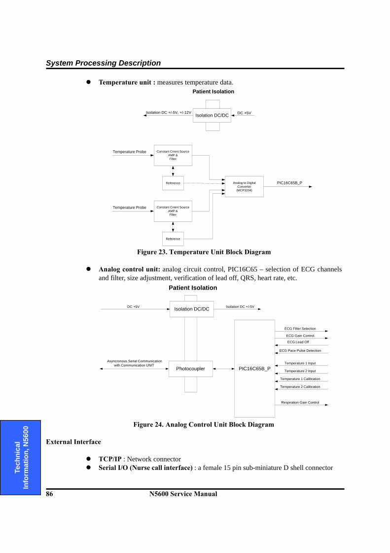
System Processing Description
86 N5600 Service Manual
Te
chni
cal
Info
rmat
ion,
N56
00
Temperature unit : measures temperature data.
DC +5VIsolation DC/DCIsolation DC +/-5V, +/-12V
Patient Isolation
Constant Crrent SourceAMP &Filter
Reference
Temperature Probe
PIC16C65B_P
Constant Crrent SourceAMP &Filter
Reference
Temperature Probe
Analog to DigitalConverter
(MCP3204)
Figure 23. Temperature Unit Block Diagram
Analog control unit: analog circuit control, PIC16C65 – selection of ECG channels
and filter, size adjustment, verification of lead off, QRS, heart rate, etc.
Asyncronous Serial Communicationwith Communication UNIT
PIC16C65B_PPhotocoupler
Isolation DC/DCDC +5V Isolation DC +/-5V
Patient Isolation
ECG Lead Off
ECG Filter Selection
Temperature 1 Input
Respiration Gain Control
ECG Pace Pulse Detection
Temperature 2 Input
ECG Gain Control
Temperature 1 Calibration
Temperature 2 Calibration
Figure 24. Analog Control Unit Block Diagram
External Interface
TCP/IP : Network connector Serial I/O (Nurse call interface) : a female 15 pin sub-miniature D shell connector

System Processing Description
N5600 Service Manual 87
Technical
Information, N
5600
10.3 ECG Processing The measurement of the skin surfaces electrocardiogram is based on the electrical signals on the skin surface, produced as the heart muscle contracts and relaxes. The signals are detected by electrodes placed on the patient body. The information on heart activity carried by these signals varies with the placing of the electrodes. The technique used in ECG senses the varying potential difference between two points at the skin surface which respond to the chemical actions of the muscular activity of the heart. Three electrodes are attached to the patient’s right arm (RA), left arm (LA) and left leg (LL). The varying potentials at these locations are cable-connected to the ECG circuit inputs where they are conditioned, and the difference of potential between two selected leads is digitized before transmitting through opto-isolators to the processor. The processor-installed algorithms operate on the signals to develop drivers for the graphic display and to compute the heart rate in beats per minute (bpm). In addition to the acquisition of the QRS waveform complex, the ECG input and subsequent signal processing computing circuitry perform a number of other functions: They detect a lead-off condition if one of the electrode connections is
disrupted. They detect the presence of pacemaker signals within the QRS waveform
complex of the ECG.
10.4 NIBP Processing Overview The oscillometric technique does not use Korotkoff sounds to determine blood pressure. The oscillometric technique monitors the changes in cuff pressure caused by the flow of blood through the artery. The monitor inflates the cuff to a pressure that occludes the artery. Even when the artery is occluded, the pumping of the heart against the artery can cause small pressure pulses in the cuff baseline pressure. The monitor lowers cuff pressure at a controlled rate. As the cuff pressure goes down, blood starts to flow through the artery. The increasing blood flow causes the amplitude of the pressure pulses in the cuff to increase. These pressure pulses continue to increase in amplitude with decreasing cuff pressure until they reach a maximum amplitude at which point they begin to decrease with decreasing cuff pressure. The cuff pressure at which the pulse amplitude is the greatest is known as Mean Arterial Pressure(MAP). The manner in which the pulse amplitudes vary is often referred to as the pulse envelope. The envelope is an imaginary line that connects the peak of each pressure pulse and forms an outline. The shape of the envelope is observed by the monitor using a variety of techniques to determine the diastolic and systolic blood pressure.
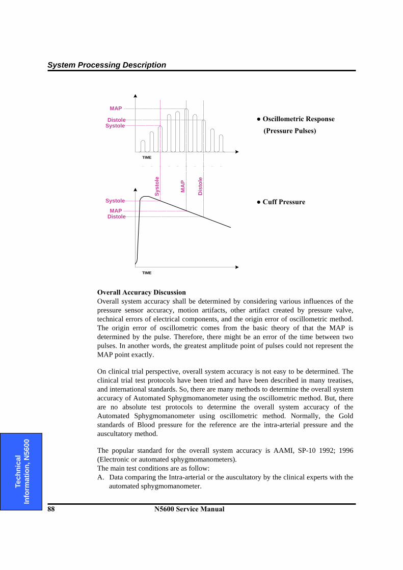
System Processing Description
88 N5600 Service Manual
Te
chni
cal
Info
rmat
ion,
N56
00
● Oscillometric Response
(Pressure Pulses)
● Cuff Pressure
Systole
Systole
MAP
Distole
MAPDistole
Dis
tole
MA
P
Syst
ole
TIME
TIME
Overall Accuracy Discussion Overall system accuracy shall be determined by considering various influences of the pressure sensor accuracy, motion artifacts, other artifact created by pressure valve, technical errors of electrical components, and the origin error of oscillometric method. The origin error of oscillometric comes from the basic theory of that the MAP is determined by the pulse. Therefore, there might be an error of the time between two pulses. In another words, the greatest amplitude point of pulses could not represent the MAP point exactly. On clinical trial perspective, overall system accuracy is not easy to be determined. The clinical trial test protocols have been tried and have been described in many treatises, and international standards. So, there are many methods to determine the overall system accuracy of Automated Sphygmomanometer using the oscillometric method. But, there are no absolute test protocols to determine the overall system accuracy of the Automated Sphygmomanometer using oscillometric method. Normally, the Gold standards of Blood pressure for the reference are the intra-arterial pressure and the auscultatory method. The popular standard for the overall system accuracy is AAMI, SP-10 1992; 1996 (Electronic or automated sphygmomanometers). The main test conditions are as follow: A. Data comparing the Intra-arterial or the auscultatory by the clinical experts with the
automated sphygmomanometer.
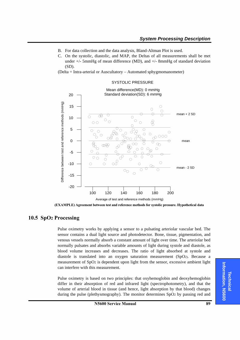
System Processing Description
N5600 Service Manual 89
Technical
Information, N
5600
B. For data collection and the data analysis, Bland-Altman Plot is used. C. On the systolic, diastolic, and MAP, the Deltas of all measurements shall be met
under +/- 5mmHg of mean difference (MD), and +/- 8mmHg of standard deviation (SD).
(Delta = Intra-arterial or Auscultatory – Automated sphygmomanometer)
20
-20
-15
-10
-5
0
5
10
15
200180160140120100
SYSTOLIC PRESSURE
Mean difference(MD): 0 mmHgStandard deviation(SD): 6 mmHg
mean + 2 SD
mean
mean - 2 SD
Average of test and reference methods (mmHg)
Diff
eren
ce b
etw
een
test
and
refe
renc
e m
etho
ds (m
mH
g)
(EXAMPLE) Agreement between test and reference methods for systolic pressure. Hypothetical data
10.5 SpO2 Processing Pulse oximetry works by applying a sensor to a pulsating arteriolar vascular bed. The sensor contains a dual light source and photodetector. Bone, tissue, pigmentation, and venous vessels normally absorb a constant amount of light over time. The arteriolar bed normally pulsates and absorbs variable amounts of light during systole and diastole, as blood volume increases and decreases. The ratio of light absorbed at systole and diastole is translated into an oxygen saturation measurement (SpO2). Because a measurement of SpO2 is dependent upon light from the sensor, excessive ambient light can interfere with this measurement. Pulse oximetry is based on two principles: that oxyhemoglobin and deoxyhemoglobin differ in their absorption of red and infrared light (spectrophotometry), and that the volume of arterial blood in tissue (and hence, light absorption by that blood) changes during the pulse (plethysmography). The monitor determines SpO2 by passing red and
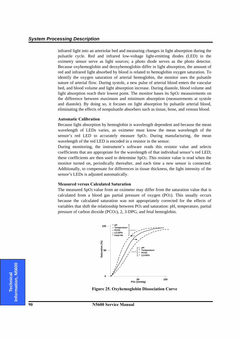
System Processing Description
90 N5600 Service Manual
Te
chni
cal
Info
rmat
ion,
N56
00
infrared light into an arteriolar bed and measuring changes in light absorption during the pulsatile cycle. Red and infrared low-voltage light-emitting diodes (LED) in the oximetry sensor serve as light sources; a photo diode serves as the photo detector. Because oxyhemoglobin and deoxyhemoglobin differ in light absorption, the amount of red and infrared light absorbed by blood is related to hemoglobin oxygen saturation. To identify the oxygen saturation of arterial hemoglobin, the monitor uses the pulsatile nature of arterial flow. During systole, a new pulse of arterial blood enters the vascular bed, and blood volume and light absorption increase. During diastole, blood volume and light absorption reach their lowest point. The monitor bases its SpO2 measurements on the difference between maximum and minimum absorption (measurements at systole and diastole). By doing so, it focuses on light absorption by pulsatile arterial blood, eliminating the effects of nonpulsatile absorbers such as tissue, bone, and venous blood. Automatic Calibration Because light absorption by hemoglobin is wavelength dependent and because the mean wavelength of LEDs varies, an oximeter must know the mean wavelength of the sensor’s red LED to accurately measure SpO2. During manufacturing, the mean wavelength of the red LED is encoded in a resistor in the sensor. During monitoring, the instrument’s software reads this resistor value and selects coefficients that are appropriate for the wavelength of that individual sensor’s red LED; these coefficients are then used to determine SpO2. This resistor value is read when the monitor turned on, periodically thereafter, and each time a new sensor is connected. Additionally, to compensate for differences in tissue thickness, the light intensity of the sensor’s LEDs is adjusted automatically. Measured versus Calculated Saturation The measured SpO2 value from an oximeter may differ from the saturation value that is calculated from a blood gas partial pressure of oxygen (PO2). This usually occurs because the calculated saturation was not appropriately corrected for the effects of variables that shift the relationship between PO2 and saturation: pH, temperature, partial pressure of carbon dioxide (PCO2), 2, 3-DPG, and fetal hemoglobin.
100
50
050 100
Satu
ratio
n (%
)
PO2 (mmHg)
pHTemperaturePCO22,3-DPGFetal Hb
pHTemperaturePCO22,3-DPG
Figure 25. Oxyhemoglobin Dissociation Curve

System Processing Description
N5600 Service Manual 91
Technical
Information, N
5600
Functional versus Fractional Saturation This monitor measures functional saturation — oxygenated hemoglobin expressed as a percentage of the hemoglobin that can transport oxygen. It does not detect significant amounts of dysfunctional hemoglobin, such as carboxyhemoglobin or methemoglobin. In contrast, hemoximeters such as the IL482 report fractional saturation — oxygenated hemoglobin expressed as a percentage of all measured hemoglobin, including measured dysfunctional hemoglobin. To compare functional saturation measurements to those from an instrument that measures fractional saturation, fractional measurements must be converted as follows: functional saturation = fractional saturation 100 – (%carboxyhemoglobin + %methemoglobin) OxiMax Technology The N5600 SpO2 monitoring is designed to use Nellcor OXIMAX brand sensors, which integrate the OXIMAX technology. These sensors can be identified by their deep blue plug color. All OXIMAX sensors contain a memory chip carrying information about the sensor which the monitor needs for correct operation, including the sensor’s calibration data, model type, troubleshooting codes, and error detection data. This unique oximetry architecture enables several new features with the N5600. When an OXIMAX sensor is connected to the N5600, the monitor will first read the information in the sensor memory chip, check it to make sure that there are no errors, and then load the data to begin monitoring. The monitor containing OxiMax Technology uses calibration data contained in the sensor in calculating the patient’s SpO2.
10.6 Respiration Processing The N5600 respiration monitoring is designed to use the variation of this thoracic impedance. The chest contains various materials, ranging from bone to air. Each of these materials has different electrical properties and is located in a different portion of the chest. The materials of the chest vary in electrical resistivity (the amount of electrical resistance between opposite faces of a cube of that material), which is an important determinant of electrical impedance in the body. Two of the major components of the chest, blood and air, are at opposite ends of the scale. Furthermore, the volume of each of these materials varies with time over the cardiac and breathing cycles. The variation of the thoracic impedance is caused by the difference between air and blood in the thoracic impedance. Blood has relatively low resistivity, which varies over the cardiac cycle owing to changing blood volumes in the heart and in the vascular compartment. Air, on the other hand, has high electrical resistivity and hence impedance, and it undergoes wide volume changes in the lungs during normal breathing. i.e. the impedance of blood is 150 ohm/cm and the one of air is 5000 ohm/cm. The patient’s respiration is detected by using two of the three leads of the ECG electrodes (RA and LA, or RA and LL) and cable. The electrical impedance between a
× 100
System Processing Description
92 N5600 Service Manual
Te
chni
cal
Info
rmat
ion,
N56
00
pair of electrodes is determined by dividing the voltage difference between the two electrodes by the current that passes between them. When the electrodes are placed on the actual structure, respective structures change. A low-level excitation signal is applied to these leads, and the variation of the thoracic impedance caused by the breathing is sensed and processed for display and measurement. This variation is processed to the voltage value for the measurement. In order to transfer the thoracic impedance by a transformer, it is used a minimum constant current of the sine wave carrier signal. The transferred thoracic impedance is changed to the voltage signal by using bridge circuit and differential amplifier. Then, ECG signal is removed by filter, and carrier frequency is removed by full wave rectifier and filter in order to extract only thoracic impedance in amplifying at the definite level of signal. This extracted thoracic impedance signal is used to measure the respiration by digital signal processing.
10.7 Temperature Processing Measurement of patient temperature is accomplished by processing the signal from a probe containing a resistor whose resistance is temperature dependent. The class of such components is called thermistor. Temperature measurement used by N5600 patient monitoring system is based on a thermistor whose resistance is inversely proportional to its temperature. By measuring the thermistor’s resistance, its temperature can be calculated. The resistance of the thermistor is measured by passing a current through it and measuring the voltage developed across it. The N5600 patient monitor is designed to accept the signals from electrically isolated a range of temperature probes from the Monotherm™ range. The probes may be used for skin or rectal temperature measurement. Probes are furnished with a standard 10-feet lead; extension leads are available. The signal from the probe is conditioned by the monitor input circuitry, processed, and used to drive the numeric display.